WO2017134883A1 - スイッチユニット、該スイッチユニットを備えた内視鏡用撮像装置、該スイッチユニットを備えた内視鏡 - Google Patents
スイッチユニット、該スイッチユニットを備えた内視鏡用撮像装置、該スイッチユニットを備えた内視鏡 Download PDFInfo
- Publication number
- WO2017134883A1 WO2017134883A1 PCT/JP2016/082324 JP2016082324W WO2017134883A1 WO 2017134883 A1 WO2017134883 A1 WO 2017134883A1 JP 2016082324 W JP2016082324 W JP 2016082324W WO 2017134883 A1 WO2017134883 A1 WO 2017134883A1
- Authority
- WO
- WIPO (PCT)
- Prior art keywords
- switch
- cover
- opening
- button
- switch unit
- Prior art date
- Legal status (The legal status is an assumption and is not a legal conclusion. Google has not performed a legal analysis and makes no representation as to the accuracy of the status listed.)
- Ceased
Links
Images










Classifications
-
- G—PHYSICS
- G02—OPTICS
- G02B—OPTICAL ELEMENTS, SYSTEMS OR APPARATUS
- G02B23/00—Telescopes, e.g. binoculars; Periscopes; Instruments for viewing the inside of hollow bodies; Viewfinders; Optical aiming or sighting devices
- G02B23/24—Instruments or systems for viewing the inside of hollow bodies, e.g. fibrescopes
- G02B23/2476—Non-optical details, e.g. housings, mountings, supports
- G02B23/2484—Arrangements in relation to a camera or imaging device
-
- A—HUMAN NECESSITIES
- A61—MEDICAL OR VETERINARY SCIENCE; HYGIENE
- A61B—DIAGNOSIS; SURGERY; IDENTIFICATION
- A61B1/00—Instruments for performing medical examinations of the interior of cavities or tubes of the body by visual or photographical inspection, e.g. endoscopes; Illuminating arrangements therefor
- A61B1/00002—Operational features of endoscopes
- A61B1/00039—Operational features of endoscopes provided with input arrangements for the user
- A61B1/00042—Operational features of endoscopes provided with input arrangements for the user for mechanical operation
-
- A—HUMAN NECESSITIES
- A61—MEDICAL OR VETERINARY SCIENCE; HYGIENE
- A61B—DIAGNOSIS; SURGERY; IDENTIFICATION
- A61B1/00—Instruments for performing medical examinations of the interior of cavities or tubes of the body by visual or photographical inspection, e.g. endoscopes; Illuminating arrangements therefor
- A61B1/00064—Constructional details of the endoscope body
- A61B1/00066—Proximal part of endoscope body, e.g. handles
-
- A—HUMAN NECESSITIES
- A61—MEDICAL OR VETERINARY SCIENCE; HYGIENE
- A61B—DIAGNOSIS; SURGERY; IDENTIFICATION
- A61B1/00—Instruments for performing medical examinations of the interior of cavities or tubes of the body by visual or photographical inspection, e.g. endoscopes; Illuminating arrangements therefor
- A61B1/00064—Constructional details of the endoscope body
- A61B1/00071—Insertion part of the endoscope body
- A61B1/0008—Insertion part of the endoscope body characterised by distal tip features
- A61B1/00096—Optical elements
-
- A—HUMAN NECESSITIES
- A61—MEDICAL OR VETERINARY SCIENCE; HYGIENE
- A61B—DIAGNOSIS; SURGERY; IDENTIFICATION
- A61B1/00—Instruments for performing medical examinations of the interior of cavities or tubes of the body by visual or photographical inspection, e.g. endoscopes; Illuminating arrangements therefor
- A61B1/00112—Connection or coupling means
- A61B1/00121—Connectors, fasteners and adapters, e.g. on the endoscope handle
-
- A—HUMAN NECESSITIES
- A61—MEDICAL OR VETERINARY SCIENCE; HYGIENE
- A61B—DIAGNOSIS; SURGERY; IDENTIFICATION
- A61B1/00—Instruments for performing medical examinations of the interior of cavities or tubes of the body by visual or photographical inspection, e.g. endoscopes; Illuminating arrangements therefor
- A61B1/00163—Optical arrangements
-
- A—HUMAN NECESSITIES
- A61—MEDICAL OR VETERINARY SCIENCE; HYGIENE
- A61B—DIAGNOSIS; SURGERY; IDENTIFICATION
- A61B1/00—Instruments for performing medical examinations of the interior of cavities or tubes of the body by visual or photographical inspection, e.g. endoscopes; Illuminating arrangements therefor
- A61B1/00163—Optical arrangements
- A61B1/00195—Optical arrangements with eyepieces
-
- A—HUMAN NECESSITIES
- A61—MEDICAL OR VETERINARY SCIENCE; HYGIENE
- A61B—DIAGNOSIS; SURGERY; IDENTIFICATION
- A61B1/00—Instruments for performing medical examinations of the interior of cavities or tubes of the body by visual or photographical inspection, e.g. endoscopes; Illuminating arrangements therefor
- A61B1/04—Instruments for performing medical examinations of the interior of cavities or tubes of the body by visual or photographical inspection, e.g. endoscopes; Illuminating arrangements therefor combined with photographic or television appliances
- A61B1/042—Instruments for performing medical examinations of the interior of cavities or tubes of the body by visual or photographical inspection, e.g. endoscopes; Illuminating arrangements therefor combined with photographic or television appliances characterised by a proximal camera, e.g. a CCD camera
-
- A—HUMAN NECESSITIES
- A61—MEDICAL OR VETERINARY SCIENCE; HYGIENE
- A61B—DIAGNOSIS; SURGERY; IDENTIFICATION
- A61B1/00—Instruments for performing medical examinations of the interior of cavities or tubes of the body by visual or photographical inspection, e.g. endoscopes; Illuminating arrangements therefor
- A61B1/04—Instruments for performing medical examinations of the interior of cavities or tubes of the body by visual or photographical inspection, e.g. endoscopes; Illuminating arrangements therefor combined with photographic or television appliances
- A61B1/05—Instruments for performing medical examinations of the interior of cavities or tubes of the body by visual or photographical inspection, e.g. endoscopes; Illuminating arrangements therefor combined with photographic or television appliances characterised by the image sensor, e.g. camera, being in the distal end portion
-
- G—PHYSICS
- G02—OPTICS
- G02B—OPTICAL ELEMENTS, SYSTEMS OR APPARATUS
- G02B23/00—Telescopes, e.g. binoculars; Periscopes; Instruments for viewing the inside of hollow bodies; Viewfinders; Optical aiming or sighting devices
- G02B23/24—Instruments or systems for viewing the inside of hollow bodies, e.g. fibrescopes
- G02B23/2407—Optical details
- G02B23/2453—Optical details of the proximal end
-
- A—HUMAN NECESSITIES
- A61—MEDICAL OR VETERINARY SCIENCE; HYGIENE
- A61B—DIAGNOSIS; SURGERY; IDENTIFICATION
- A61B1/00—Instruments for performing medical examinations of the interior of cavities or tubes of the body by visual or photographical inspection, e.g. endoscopes; Illuminating arrangements therefor
- A61B1/00064—Constructional details of the endoscope body
- A61B1/00105—Constructional details of the endoscope body characterised by modular construction
-
- G—PHYSICS
- G02—OPTICS
- G02B—OPTICAL ELEMENTS, SYSTEMS OR APPARATUS
- G02B23/00—Telescopes, e.g. binoculars; Periscopes; Instruments for viewing the inside of hollow bodies; Viewfinders; Optical aiming or sighting devices
- G02B23/24—Instruments or systems for viewing the inside of hollow bodies, e.g. fibrescopes
- G02B23/2476—Non-optical details, e.g. housings, mountings, supports
- G02B23/2492—Arrangements for use in a hostile environment, e.g. a very hot, cold or radioactive environment
Definitions
- the present invention includes a switch unit that holds the inside of a switch cover that is watertightly fixed to the opening on the outer surface of the exterior member, an endoscope imaging device including the switch unit, and the switch unit. It relates to an endoscope.
- an endoscope imaging apparatus As an apparatus having a switch unit that keeps the inside watertight, for example, an endoscope imaging apparatus is well known.
- An endoscope imaging apparatus captures an image of a test site in a subject and outputs the captured image of the test site to a monitor, for example, on the proximal end side of an insertion portion of the endoscope A configuration that can be connected to an eyepiece provided (hereinafter referred to as an eyepiece) is well known.
- an autoclave process for sterilization using high-temperature high-pressure steam is well known.
- an internal unit including an imaging unit including an imaging element, an objective optical system, and the like in the endoscope imaging apparatus is provided in an exterior member of the endoscope imaging apparatus.
- high temperature and high pressure steam also enters the exterior member.
- the imaging unit touches the high-temperature and high-pressure steam, the imaging device may break down or the objective optical system may become cloudy. Need to be provided.
- Japanese Patent Application Laid-Open No. 2013-56003 provides an airtight case made of a metal such as stainless steel in an exterior member in an endoscope imaging device mounted on an eyepiece of an endoscope.
- the structure which seals an internal unit in this airtight case is disclosed. With this configuration, the imaging unit in the internal unit can be protected by the airtight case from the high-temperature and high-pressure steam that has entered the exterior member.
- Japanese Unexamined Patent Publication No. 2013-56003 discloses a configuration in which a switch unit is provided in a watertight manner on an exterior member of an endoscope imaging apparatus.
- the switch unit includes a focus adjustment button that adjusts the focus by moving a part of the lens of the imaging unit of the internal unit back and forth, and a zoom that adjusts the focus magnification by moving a part of the lens back and forth.
- a switch constituting each button is fitted into an opening provided in the exterior member for each switch, and is fixed to a switch fixing member provided in each opening for each switch. Furthermore, a switch cover covered for each switch is fixed in a watertight manner to each opening, so that a part is exposed on the outer surface of the exterior member so that the operator can perform a pressing operation. .
- a near point button and a far point button which are focus adjustment buttons, are provided independently of each other.
- a Wide button and a Tele button which are zoom buttons, are provided independently of each other.
- buttons provided on the outer surface of the exterior member of the endoscope imaging apparatus increases, and there is a problem that it is difficult for the operator to recognize a desired button.
- the near point button and the far point button are integrated as one focus adjustment button, and the Wide button and the Tele button are integrated as one zoom button. With this configuration, the number of buttons can be reduced and the operator can easily recognize a desired button.
- a near point switch and a far point switch are fitted into one opening of the exterior member and fixed to one switch fixing member provided in the opening. It is well known that one switch cover that covers the point switch and the far point switch together is fixed to one opening in a watertight manner. The above configuration is the same for the zoom button.
- the pressure in the switch cover changes to a negative pressure or a positive pressure with respect to the atmospheric pressure.
- each switch cover at the position between the near point switch and the far point switch on the focus adjustment button and the position between the Wide switch and the Tele switch on the zoom button is raised and lowered by the positive and negative pressure in the switch cover. .
- the operability of each button is lowered.
- the focus adjustment button and the zoom button are integrated, and when the Wide button and the Tele button that are the zoom buttons are integrated, the focus adjustment button and This is because the surface area of the zoom button is larger than the surface area when each button is provided independently.
- the present invention has been made in view of the above problems, and is a switch unit having a configuration that prevents ups and downs between switches of a switch cover that covers a plurality of switches by means of a negative and positive pressure inside the switch cover held in a watertight manner.
- An object of the present invention is to provide an endoscope imaging device including the switch unit and an endoscope including the switch unit.
- the switch unit includes a plurality of switches provided separately from each other in an opening provided on an outer surface of an exterior member, and the plurality of switches provided in the opening.
- a switch fixing member that is fixed to the switch, a plurality of switches and one switch cover that covers the plurality of switch fixing members and is fixed to the opening in a watertight manner, and the switch formed between the switches.
- an endoscope imaging apparatus including a switch unit according to an aspect of the present invention includes the switch unit.
- an endoscope including a switch unit includes the switch unit.
- FIG. 3 is an enlarged partial cross-sectional view of a portion surrounded by an IV line in the camera head of FIG. 4 is a partial cross-sectional view showing a modification in which the locking portion of FIG. 4 is provided on the switch fixing member.
- 4 and 5 are partial cross-sectional views showing a modification in which the locking portion is applied to a seesaw type button.
- FIG. 3 is a partial cross-sectional view schematically showing a fixing configuration of a conventional hermetic connector surrounded by a line XI in FIG. Partial sectional view schematically showing the fixing configuration of the hermetic connector of this configuration FIG.
- FIG. 3 is a perspective view of the front sealing type exterior member of FIG.
- substrate which does not use the hermetic connector from the opening part of the airtight case of FIG. 14 is a partial cross-sectional view taken along line XV-XV in FIG. 14 with the front cover fixed to the main cover in FIG.
- FIG. 16 is a partial cross-sectional view showing a modified example in which the insertion hole of the main cover of FIG.
- FIG. 3 is a partial sectional view schematically showing a configuration in which a circumferential watertight member is provided on the outer peripheral surface of the switch button frame of FIG.
- 18 is a partial cross-sectional view schematically showing a configuration in which the watertight member of FIG. 18 is provided on the bottom surface of the switch button frame.
- 19 is a partial cross-sectional view schematically showing a configuration in which the watertight member of FIG. 19 is provided on an inclined surface connecting the outer peripheral surface and the bottom surface of the switch button frame.
- 20 is a partial cross-sectional view schematically showing a configuration of a modification in which the watertight member of FIG. 20 is formed in an L-shaped cross section.
- FIG. 1 is a diagram showing an outline of a configuration of an endoscope system including an endoscope imaging device having a switch unit of the present embodiment.
- the endoscope system 1 includes an endoscope 2 and an endoscope imaging device that can be connected to the endoscope 2 and a switch unit 270 (see FIG. 2) described later.
- a camera head 3 and a light source device 4 for supplying illumination light to the endoscope 2 are provided.
- the endoscope system 1 also includes a camera control unit (CCU) 5 that performs signal processing on an image pickup signal from the camera head 3 and a monitor 6 that displays a video signal output from the CCU 5. ing.
- CCU camera control unit
- the endoscope 2 includes an elongated insertion portion 7, a gripping portion 8 having a larger diameter than the insertion portion 7 provided on the proximal end side of the insertion portion 7, and an eyepiece provided on the proximal end of the gripping portion 8
- the main part is comprised.
- one end of the light guide cable 10 detachably attached to the light source device 4 via the connector 11 is connectable to a base provided on the side portion of the grip portion 8 of the endoscope 2.
- the image in the subject illuminated by the illumination light forms an optical image on an objective optical system (not shown) provided at the distal end of the insertion portion 7.
- the formed optical image is incident on a lens provided in the eyepiece 9 via a relay lens (not shown) provided in the insertion portion 7.
- a relay lens not shown
- the camera head 3 can be connected to the eyepiece 9 of the endoscope 2.
- a camera cable 12 extends from the camera head 3, and an extended end of the camera cable 12 is detachable from the CCU 5 via a connector 13 provided at the extended end.
- the CCU 5 generates an image signal based on an imaging signal transmitted from the camera head 3 via the camera cable 12, and displays an image in the subject on the monitor 6 as an endoscopic image.
- FIGS. 2 is a perspective view showing the camera head of FIG. 1
- FIG. 3 is a partial sectional view of the camera head along the line III-III in FIG. 2
- FIG. 4 is surrounded by the IV line in the camera head of FIG. FIG.
- the camera head 3 includes a coupler portion 15 and an exterior member 17 having a distal end fixed to the coupler portion 15 to constitute a main portion.
- the coupler unit 15 is a member to which the eyepiece 9 of the endoscope 2 is connected, and is fixed to the outer periphery on the distal end 17ak side of the exterior member 17 using a fixing screw 32. Yes.
- the exterior member 17 is made of a single layer made of metal while keeping the inside airtight, and includes a main cover 17a and a rear cover 17b fixed to the base end of the main cover 17a in a watertight and airtight manner by soldering, welding, or the like. It is composed of That is, the exterior member 17 also serves as an airtight case.
- titanium is mentioned, for example.
- a metal which comprises the exterior member 17 a lightweight and low thermal conductivity thing is desirable.
- any metal such as stainless steel may be used as long as it can be hermetically welded to prevent the high-temperature and high-pressure steam from entering the interior 17i in the autoclave process described above.
- a switch used for imaging operation of an image in the subject is provided on one side surface of the outer surface 17ag of the main cover 17a, specifically, on the outer surface 17ag at the upper part in the drawing shown in FIG.
- a unit 270 is fixed along the longitudinal direction N of the camera head 3. The detailed configuration of the switch unit 270 will be described later.
- an internal unit 150 having an imaging unit 100 is provided in an internal 17 i hermetically sealed by the exterior member 17.
- the imaging unit 100 includes a plurality of lenses 30, a lens frame 51 that holds the lenses 30, an imaging element 33, and electrical components such as various substrates, and the main part is configured.
- the plurality of lenses 30 are located in the distal end 17ak of the main cover 17a with respect to the observation window 31 that is airtightly fixed by solder or the like by metallizing the outer periphery. Opposite the longitudinal direction N.
- the observation window 31 is positioned facing the lens in the eyepiece 9 in the longitudinal direction N.
- a plurality of lenses 30 held by a lens frame 51 are provided behind the observation window 31 in the interior 17 i of the exterior member 17, and the imaging element 33 is positioned at the imaging position of the plurality of lenses 30. is doing.
- the lens frame 51 and the image sensor 33 are held by a fixed frame 120 provided between the lens frame 51 and the image sensor 33 in the longitudinal direction N.
- the fixed frame 120 holds the internal unit 150, and is made of metal in order to release heat from the image sensor 33.
- the fixing frame 120 has one or more fixing parts 120y (not shown) for fixing the internal unit 150 to the inner surface 17n of the main cover 17a (in FIG. 3, the fixing part 120 is fixed). Only one 120y is shown).
- a through hole (not shown) penetrating in the longitudinal direction N is formed in the fixing portion 120y, and a screw 60 inserted through the through hole is connected to the inner surface 17n via a washer (not shown) covered on the outer periphery of the screw 60.
- a screw 60 inserted through the through hole is connected to the inner surface 17n via a washer (not shown) covered on the outer periphery of the screw 60.
- the fixing portion 120y is fixed to the inner surface 17n via the metal. That is, the fixed frame 120 is fixed to the inner surface 17n.
- the various substrates are electrically connected to a substrate 35 located behind the substrate folder 200 via a flexible substrate 138 bent in a U shape.
- the substrate folder 200 and the substrate 35 are fixed to the frame 28 fixed to the outer periphery of the fixed frame 120.
- a connector 38a of a flexible board 38 that is bent upside down from the flexible board 138 and is extended from the board 35 is electrically connected to the board 35.
- the connector 38 b provided at the extending end of the flexible substrate 38 is electrically connected to the substrate 320 provided to be inclined rearward of the substrate 35.
- a hermetic connector 160 fixed to the inner surface 17n at the end of the rear cover 17b by welding or the like is provided on the base end side of the substrate 320, and a substrate 45 is provided on the base end side of the hermetic connector 160. It has been.
- the hermetic connector 160 is provided with a plurality of conducting pins 42 penetrating the hermetic connector 160, and the substrate 320 and the substrate 45 are electrically connected by the conducting pins 42.
- the distal end of a cable fixing frame 41 made of metal is connected to the proximal end side of the rear cover 17 b via a hermetic connector 160.
- a spacer ring 179 is fixed to the base end of the cable fixing frame 41, and the distal end of the camera cable 12 is connected to the inner peripheral surface of the spacer ring 179.
- a plurality of electric cords made of, for example, a resin material are accommodated on the outer periphery of a metal conductor, and the ends of the electric cords are extended into the cable fixing frame 41, and the board 45 is electrically connected.
- the outer peripheral surface of the camera cable 12 is covered with a bend preventing 44 that prevents the camera cable 12 from being bent suddenly.
- a rear screw 50 is movably covered on the outer periphery of the bend stopper 44, and the front end side of the camera cable 12 is fixed to the cable fixing frame 41 in a watertight and airtight manner by the rear screw 50.
- an exterior made of a resin material such as Radel (registered trademark) or PEEK so as to cover the outer periphery of the rear cover 17b and the outer periphery of the base end side of the cable fixing frame 41 from the front end of the rear cover 17b to the front end of the rear screw 50.
- a cover 40 is provided.
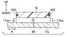
- the outer surface 17ag at the upper part of the main cover 17a in the figure has a predetermined size and a predetermined depth in the UP-DOWN direction in the figure, and the periphery of the main cover 17a
- An opening 90 is formed that is covered with a wall portion 17aw that rises in the UP direction from the outer surface 17ag on the upper side of 17a.
- the opening 90 does not communicate with the interior 17 i of the exterior member 17, and the upper outer surface 17ag of the main cover 17 a constitutes the bottom of the opening 90.
- the switch unit 270 is inserted into the opening 90 and fixed in a watertight manner.
- the switch unit 270 includes a plurality of switch buttons 71 to 75 and a switch button that is a frame that attaches the plurality of switch buttons 71 to 75 to the opening 90 through a watertight member 230 in a watertight manner.
- the main part is configured by including the frame 18 and the substrate 220.
- the switch button 71 is a focus adjustment button in which a part of the lens 30 is moved back and forth to perform focus adjustment and a near point button and a far point button are integrated into one.
- the switch button 71 fixes the far point switch 71a, the near point switch 71b provided in the longitudinal direction N away from the far point switch 71a, and the far point switch 71a and the near point switch 71b to the opening 90. And a switch fixing member 271 for ensuring watertightness.
- the switch button 71 includes a flexible switch cover 171 that covers the far point switch 71a, the near point switch 71b, and the switch fixing member 271.
- the switch button 72 is a zoom button in which a part of the lens 30 is moved back and forth to adjust the focus magnification and the Wide button and the Tele button are integrated into one.
- the switch button 72 includes a wide switch (not shown), a tele switch (not shown) spaced apart from the wide switch in a direction substantially perpendicular to the longitudinal direction N, a wide switch and a tele switch fixed to the opening 90 and watertight. And a switch fixing member 272 for securing.
- the switch button 72 includes a flexible switch cover 172 that covers the Wide switch, the Tele switch, and the switch fixing member 272.
- the switch button 73 is a brightness adjustment button, and a switch (not shown), a switch fixing member (not shown) for securing the water tightness as well as fixing the switch to the opening 90, and a flexible one covering the switch and the switch fixing member.
- a switch cover 173 (not shown) is provided to constitute a main part.
- the switch button 74 is a color adjustment button, a switch (not shown), a switch fixing member (not shown) for securing the water tightness and fixing the switch to the opening 90, and a flexible one (not shown) covering the switch and the switch fixing member.
- a main part is configured including a switch cover 174 (not shown).
- the switch cover 174 is tightened and fitted on the outer periphery of the switch fixing member for the switch button 74.
- the switch button 75 is a release button, which fixes the switch 75a, the switch 75a to the opening 90, and a switch fixing member 275 for ensuring watertightness, and a flexible switch cover that covers the switch 75a and the switch fixing member 275.
- the main part is comprised.
- the switch cover 175 is fastened and fitted to the outer periphery of the switch fixing member 275.
- the switch button frame 18 is made of, for example, resin, and covers a part of the DOWN direction side so that the UP direction side of the various switch covers 171 to 175 of the switch buttons 71 to 75 is exposed, and various switch covers 171 to 175. Is watertight.
- an outward flange 171 f provided on the outer periphery of the bottom portion of the switch cover 171 on the DOWN direction side is DOWN of the insertion hole 18 h of the switch button 71 locked to the switch button frame 18. Locked to the open end of the bottom on the side.
- the switch cover 171 is fixed to the switch button frame 18 in a watertight manner.
- the watertight configuration of the switch cover 171 is the same for the various switch covers 172 to 175.
- the switch button frame 18 has the outer peripheral surfaces of the cover portions of the various switch covers 171 to 175 in contact with the inner peripheral surface of the wall portion 17aw in a watertight manner through a circumferential watertight member 230. Has been.
- the switch button frame 18 is fixed to the opening 90 in a watertight manner.
- the switch button frame 18 includes a plurality of elastically deformable claw portions 18f (in FIG. 4, with a set interval in the outer peripheral direction on the outer periphery of the bottom portion on the DOWN direction side provided in the covering portion. Only one claw portion 18f is shown) is locked by a snap fit to a locking projection 17ad provided protruding from the wall portion 17aw to the inside of the opening 90.
- the switch button frame 18 is fixed to the outer surface 17ag on the upper side of the main cover 17a by one screw 19. Thereby, the switch button frame 18 is fixed to the opening 90 in a watertight manner.
- the substrate 220 is provided in the interior 17i of the exterior member 17 and electrically connected to the substrate held in the substrate folder 200 via a hermetic connector 310 (see FIG. 11) described later.
- the locking portion is provided in the switch cover 171 so as to project from the position between the far point switch 71 a and the near point switch 71 b toward the switch fixing member 271 in the DOWN direction. It is comprised from the convex nail
- the claw portion 171t passes through a through hole 271h formed in the switch fixing member 271 so as to penetrate in the UP-DOWN direction at a position facing the claw portion 171t and is locked to the switch fixing member 271. .
- the positive / negative pressure in the switch cover 171 prevents the switch cover 171 from rising and sinking at a position between the far point switch 71a and the near point switch 71b in the switch button 71, for example. Is done.
- the shape and locking configuration of the claw portion 172t are the same as the shape and locking configuration of the claw portion 171t.
- the switch button 71 adjusts the focus by moving a part of the lens 30 back and forth, and the focus adjustment in which the near point button and the far point button are integrated into one. Shown as a button.
- the switch button 72 is a zoom button in which a part of the lens 30 is moved back and forth to adjust the focus magnification and the Wide button and the Tele button are integrated into one.
- the locking portion of the switch cover 171 with respect to the switch fixing member 271 is provided between the far point switch 71a and the near point switch 71b in the switch button 71.
- the locking portion is a convex claw portion 171t that protrudes in the DOWN direction toward the switch fixing member 271 from the position between the far point switch 71a and the near point switch 71b in the switch cover 171. It is shown that it is composed of
- claw portion 171t is shown to be locked to the switch fixing member 271 through the through hole 271h formed in the switch fixing member 271.
- the near point button and the far point button are integrated and the surface area of the switch button 71 is increased.
- the ups and downs of the switch cover 171 at the position of the switch button 71 between the far point switch 71a and the near point switch 71b due to the negative and positive pressure in the switch cover 171 during the autoclave process of the camera head 3 can be prevented.
- a convex claw portion 172t which is a locking portion of the switch cover 172 with respect to the switch fixing member 272, is provided between the Wide switch and the Tele switch in the switch button 72.
- the wide button and the Tele button are integrated by locking the claw portion 172t provided on the switch cover 172 with the switch fixing member 272, and the surface area of the switch button 72 is increased. Even if it is, the switch cover 172 can be prevented from rising and sinking at the position between the Wide switch and the Tele switch in the switch button 72 due to the negative and positive pressure in the switch cover 172 when the camera head 3 is autoclaved. .
- the switch unit 270 having a configuration for preventing the rise and sink between the switches of the switch cover covering the plurality of switches by the negative and positive pressure inside the switch cover held in a watertight manner, and the camera head including the switch unit 270 3.
- An endoscope 2 including the switch unit 270 can be provided.
- FIG. 5 is a partial cross-sectional view showing a modification in which the locking portion of FIG. 4 is provided on the switch fixing member.
- the locking portion of the switch cover 171 with respect to the switch fixing member 271 is provided between the far point switch 71a and the near point switch 71b in the switch button 71.
- the locking portion is configured by a convex claw portion 171t that protrudes in the DOWN direction from the position between the far point switch 71a and the near point switch 71b toward the switch fixing member 271 in the switch cover 171. I showed that.
- the locking portion of the switch button 71 protrudes from the switch fixing member 271 toward the switch cover 171 in the UP direction side, and is formed on the switch cover 171. You may be comprised from the convex-shaped nail
- the locking portion of the switch button 72 is also provided on the switch fixing member 272 so as to project toward the switch cover 172 in the UP direction, and in the groove formed in the switch cover 172. You may be comprised from the convex-shaped nail
- FIG. 6 is a partial cross-sectional view showing a modification in which the locking portion of FIGS. 4 and 5 is applied to a seesaw type button.
- the locking portion of the switch cover 171 with respect to the switch fixing member 271 shown in FIGS. 4 and 5 is applicable even when the switch button 71 has a seesaw type button structure.
- the switch terminal 371 that is tilted in the direction B or C via the switch cover 171 contacts the switch cover 171. Even if the locking portion shown in FIGS. 4 and 5 is applied to the part surrounded by the line A in FIG. 6 in the part, the same effect as the above-described embodiment can be obtained.
- the configuration of the seesaw type button shown in FIG. 6 is also applicable to the switch button 72.
- the switch buttons 71 and 72 are shown as an example in which each of the switch buttons 71 and 72 has two switches.
- the present invention is not limited to this and has three or more switches.
- the present invention can be applied even in the case of
- FIG. 7 is a partial sectional view showing a modification of the shape of the claw part of the switch button frame of FIG. 3 together with a part of the main cover, and FIG. 8 is different from FIG. 7 of the claw part of the switch button frame of FIG. It is a fragmentary sectional view showing a modification of shape.
- the switch button frame is secured to the circumferential watertight member 230 by locking the plurality of claw portions 18f to the locking projections 17ad.
- the pressure can be applied evenly from 18.
- a rib 18pr may be formed on the stop portion 18p.
- FIG. 9 is a partial cross-sectional view showing a modification of the shape of the watertight member before assembly in FIG. 3 together with a part of the switch button frame and the main cover
- FIG. 10 shows a state after the watertight member in FIG. 9 is assembled. It is a fragmentary sectional view shown with a switch button frame and a part of main cover.
- the switch button frame 18 is assembled in a watertight manner with respect to the opening 90 via a watertight member 230.
- the water tight member 230 is configured to have a substantially rectangular cross section in which a plurality of protrusions 230d are formed on the outer periphery so that the crushing scale is set large as shown in FIGS. Is well known.
- an inclined surface 230dk is formed on the protrusion 230d in this configuration, as shown in FIG.
- the inclined surface 230dk reduces the passage resistance of the watertight member 230 when the watertight member 230 is crushed in the DOWN direction and the switch button frame 18 is assembled to the opening 90, so that the insertability of the watertight member 230 can be improved. .
- the switch button frame 18 can be assembled to the opening 90 with a smaller force than in the past.
- the rib 230r is formed in the protrusion 230d of the watertight member 230 at a position facing the gap S that is generated when the switch button frame 18 is assembled to the opening 90 and exposed to the outside. Yes.
- FIG. 11 is a partial cross-sectional view schematically showing a fixing configuration of a conventional hermetic connector surrounded by a line XI in FIG. 3, and
- FIG. 12 is a partial cross-sectional view schematically showing a fixing configuration of the hermetic connector of this configuration. is there.
- the substrate 220 of the switch unit 270 is electrically connected to the substrate fixed to the substrate folder 200 in the interior 17i of the exterior member 17 via the hermetic connector 310. It showed.
- the hermetic connector 310 is fixed in such a manner that the opening 90 and the interior 17i communicate with each other at a portion communicating with the opening 90 on the upper side of the main cover 17a.
- the step portion 310p of the hermetic connector 310 is brought into contact with the step portion 17ap of the hole 17ah via a ring-shaped solder 309.
- the solder 309 is melted and the hermetic connector 310 is dropped in the DOWN direction to the position where the stepped portion 310p hits the stepped portion 17ap, and the method and configuration are hermetically sealed.
- the hermetic connector 310 may be hermetically sealed in a tilted state. Therefore, the sealing quality (strength and airtightness) of the hermetic connector 310 may be deteriorated.
- the hermetic connector 310 is not tilted and the position of the hermetic connector 310 in the UP-DOWN direction is not changed.
- FIG. 13 is a perspective view of the front sealing type exterior member of FIG. 3
- FIG. 14 is a perspective view showing a configuration of pulling out a substrate from the opening of the airtight case of FIG. 13 without using a hermetic connector
- FIG. It is a fragmentary sectional view which follows the XV-XV line
- the exterior member 17 is shown to seal the inside 17i in a watertight and airtight manner by sealing the base end side of the main cover 17a with the rear cover 17b.
- FIG. 15 a configuration in which the inside 17i is sealed in a watertight and airtight manner by sealing the front end side of the main cover 17a shown in FIG. 13 with the front cover 17c is also conceivable.
- the configuration shown in FIGS. 13 to 15 is conceivable as a configuration in which the substrate 220 is connected to the conduction pin 42 without using the hermetic connector 310.
- the main cover 17a is formed with an inclined hole 90h having one end opened as an opening 90ha in the opening 90 and the other end opened as an opening 90hb in the rear cover 17b that seals the base end of the main cover 17a.
- a configuration in which the extension substrate 221 is pulled out from the opening 90 through the inclined hole 90h is conceivable.
- the extension board 221 of the board 220 can be pulled out to the rear of the rear cover 17b outside the opening 90 through the inclined hole 90h and electrically connected to the conduction pin 42.
- FIG. 16 is a partial cross-sectional view schematically showing a method of fixing the hermetic connector to the main cover of FIG. 3, and FIG. 17 is a modified example in which the insertion hole of the main cover of FIG. It is a fragmentary sectional view shown with a hermetic connector.
- the hermetic connector 310 is fixed to the insertion hole 17ah of the main cover 17a via the solder 309.
- the hermetic connector 310 is fixed to the UP direction side of the main cover 17a.
- the internal portion 17i may be corroded. Therefore, it is necessary to wipe off the flux in the internal portion 17i after fixing the solder, but there is a problem that it is difficult to wipe off the flux that has leaked into the internal portion 17i.
- the exterior member 17 is turned upside down in the UP-DOWN direction, and the fixing jig 341 is inserted from the inside 17i side.
- the hermetic connector 310 may be urged and fixed to the hot plate 340 that melts the solder 309 using the above.
- the heat transfer from the hot plate 340 to the solder 309 is improved.
- the flux leaks not to the inside 17i but to the opening 90 side, the amount of flux entering the inside 17i can be reduced, and the wiping property of the flux is improved.
- the insertion hole 17ah may have a shape without the step portion 17ap, and the step portion 310p of the hermetic connector 310 may be in contact with the vicinity of the opening end of the insertion hole 17ah in the inner portion 17i. .
- FIG. 18 is a partial cross-sectional view schematically showing a configuration in which a circumferential watertight member is provided on the outer peripheral surface of the switch button frame of FIG. 3 together with a part of the main cover
- FIG. 19 is a diagram of the watertight member of FIG.
- FIG. 20 is a partial sectional view schematically showing the configuration provided on the bottom surface of the switch button frame.
- FIG. 20 shows a configuration in which the watertight member of FIG. 19 is provided on an inclined surface connecting the outer peripheral surface and the bottom surface of the switch button frame.
- FIG. 21 is a partial cross-sectional view schematically showing a configuration of a modified example in which the watertight member of FIG. 20 is formed in an L-shaped cross section.
- the watertight member 230 may be formed on an inclined surface 18q connecting the outer peripheral surface and the bottom surface of the switch button frame 18.
- the watertight member 230 since the watertight member 230 also has a tapered cross section, not only resistance during press-fitting is reduced, but also a wedge using the inclined surface 18q when the switch button frame 18 is pushed in the DOWN direction. Due to the effect, the watertight member 230 is easily crushed.
- the watertight member 230 may be formed in an L-shaped cross section extending from the inclined surface 18q to the bottom surface side.
- FIG. 22 is a perspective view showing a modification of the shape of the claw portion of the switch button frame of FIG.
- the switch button frame 18 has been shown that a plurality of elastically deformable claw portions 18f are locked to the locking protrusions 17ad by snap fitting.
- the switch button frame 19 is fixed to the opening 90 in a watertight manner by being fixed to the outer surface 17ag on the upper side of the main cover 17a by one screw 19.
- a position farthest from the screw 19 for example, a claw portion 18f at the tip position of the switch button frame 18 is formed large in the outer peripheral direction of the switch button frame 18 and does not elastically deform. It may be formed on the rigid claw portion 18v. Note that the claw portion 18v is only caught on the locking projection 17ad.
- one screw 19 is provided by setting the claw portion farthest from the screw 19 as the rigid claw portion 18v as compared with the case where the claw portion is entirely made of an elastically deformable one. Even in the configuration in which only the switch button frame 18 is used, the fixing strength of the switch button frame 18 is further improved. That is, the resistance due to the external force of the switch button frame 18 is improved.
- FIG. 23 is a perspective view showing a watertight member for the gold ring in FIG. 3
- FIG. 24 is a perspective view showing the gold ring in FIG.
- the inner periphery on the front end side of the exterior cover 40 is watertightly fixed to the outer periphery on the front end side of the rear cover 17 b through a circumferential watertight member 252.
- the outer periphery on the distal end side of the exterior cover 40 it is a known index that allows the operator to visually recognize the function of the camera head and the like at a position between the distal end of the exterior cover 40 and the base end of the main cover 17a.
- a gold ring 250 is provided.
- a locking projection 251t is provided on a part of the watertight member 251, and the locking projection 251t is locked to the gold ring 250 as shown in FIG.
- a stop groove 250m may be formed.
- the rotation of the watertight member 251 in the rotational direction is prevented by the locking of the locking protrusion 251t with respect to the locking groove 250m.
- the watertightness of the watertight member 251 can be sufficiently secured, and the watertight member 251 can be prevented from protruding.
- the same effect can be acquired also in the structure by which the latching protrusion is provided in the gold ring 250 and the locking groove is provided in the watertight member 251.
- the switch unit 270 is described as being used for the camera head 3. However, it is needless to say that the switch unit 270 may be used for the endoscope 2 alone.
Landscapes
- Health & Medical Sciences (AREA)
- Life Sciences & Earth Sciences (AREA)
- Surgery (AREA)
- Physics & Mathematics (AREA)
- Optics & Photonics (AREA)
- Engineering & Computer Science (AREA)
- Medical Informatics (AREA)
- General Health & Medical Sciences (AREA)
- Pathology (AREA)
- Nuclear Medicine, Radiotherapy & Molecular Imaging (AREA)
- Biomedical Technology (AREA)
- Heart & Thoracic Surgery (AREA)
- Biophysics (AREA)
- Molecular Biology (AREA)
- Animal Behavior & Ethology (AREA)
- Radiology & Medical Imaging (AREA)
- Public Health (AREA)
- Veterinary Medicine (AREA)
- Astronomy & Astrophysics (AREA)
- General Physics & Mathematics (AREA)
- Multimedia (AREA)
- Mechanical Engineering (AREA)
- Instruments For Viewing The Inside Of Hollow Bodies (AREA)
- Endoscopes (AREA)
- Push-Button Switches (AREA)
Abstract
外装部材の外表面に設けられた開口部90においてそれぞれ離間して設けられた複数のスイッチ71a、71bと、開口部90に設けられた、複数のスイッチ71a、71bを開口部90に固定するスイッチ固定部材271と、複数のスイッチ71a、71b及びスイッチ固定部材271を覆うとともに、開口部90に水密的に固定される柔軟な1つのスイッチカバー171と、スイッチ71a、71b間に形成された、スイッチ固定部材271に対するスイッチカバー171の係止部171tと、を具備する。
Description
本発明は、外装部材の外表面の開口部に水密的に固定されるスイッチカバーの内部を水密に保持するスイッチユニット、該スイッチユニットを備えた内視鏡用撮像装置、該スイッチユニットを備えた内視鏡に関する。
内部を水密に保持するスイッチユニットを有する装置として、例えば内視鏡用撮像装置が周知である。
内視鏡用撮像装置は、被検体内における被検部位の像を撮像し、該撮像した被検部位の像をモニタに出力するものであり、例えば内視鏡の挿入部の基端側に設けられた接眼部(以下、アイピースと称す)に接続自在な構成が周知である。
また、内視鏡用撮像装置は、使用後、確実に洗浄、消毒及び滅菌する必要がある。内視鏡用撮像装置の滅菌方法としては、高温高圧蒸気を用いて滅菌する高温高圧蒸気滅菌処理(以下、オートクレーブ処理と称す)が周知である。
ここで、通常、内視鏡用撮像装置における撮像素子、対物光学系等からなる撮像ユニットを具備する内部ユニットは、内視鏡用撮像装置の外装部材内に設けられている。オートクレーブ処理において、外装部材内にも高温高圧蒸気が進入する。
この際、撮像ユニットは、高温高圧蒸気に触れると、撮像素子が故障してしまったり、対物光学系が曇ったりしてしまうことから、撮像ユニットは、外装部材内において高温高圧蒸気が進入しない場所に設けられる必要がある。
そこで、日本国特開2013-56003号公報には、内視鏡の接眼部に装着される内視鏡用撮像装置において、外装部材内にステンレス等の金属から構成された気密ケースを設け、該気密ケース内に内部ユニットを封止する構成が開示されている。この構成により、外装部材内に進入した高温高圧蒸気から内部ユニットにおける撮像ユニットを気密ケースによって保護することができる。
また、日本国特開2013-56003号公報には、内視鏡用撮像装置の外装部材に、スイッチユニットが水密的に設けられた構成が開示されている。尚、スイッチユニットとしては、内部ユニットの撮像ユニットが具備するレンズの一部を前後に移動させて焦点調整を行う焦点調整ボタンや、レンズの一部を前後に移動させて焦点倍率を調整するズームボタンや、明るさ調整ボタンや、色調整ボタンや、レリーズボタン等が挙げられる。
これらのボタンは、各ボタンを構成するスイッチが、外装部材にスイッチ毎に設けられた開口部に嵌入されて、スイッチ毎に各開口部に設けられたスイッチ固定部材に固定される。さらに、スイッチ毎に被覆されたスイッチカバーが各開口部に水密的にそれぞれ固定されることにより、操作者が押下操作を行うことができるよう外装部材の外表面に一部が露出して設けられる。
ここで、日本国特開2013-56003号公報に開示された内視鏡用撮像装置においては、焦点調節ボタンである近点ボタンと遠点ボタンとはそれぞれ独立して設けられている。さらに、ズームボタンであるWideボタンとTeleボタンとがそれぞれ独立して設けられている。
よって、内視鏡用撮像装置の外装部材の外表面に設けられるボタン数が多くなってしまい、操作者は、所望のボタンを認識し難いといった問題があった。
このような問題に鑑み、近点ボタンと遠点ボタンとが1つの焦点調節ボタンとして一体化されるとともに、WideボタンとTeleボタンとが1つのズームボタンとして一体化される構成も周知である。この構成により、ボタン数を減らすとともに操作者に所望のボタンを認識させやすくすることができる。
具体的には、例えば焦点調節ボタンであれば、外装部材の1つの開口部に、近点スイッチと遠点スイッチとが嵌入されて開口部内に設けられた1つのスイッチ固定部材に固定され、近点スイッチ及び遠点スイッチをまとめて覆う1つのスイッチカバーが、1つの開口部に水密的に固定される構成が周知である。尚、以上の構成は、ズームボタンにおいても同様である。
ここで、内視鏡用撮像装置に対して、上述したオートクレーブ処理を行うと、スイッチカバー内の圧力が大気圧に対して陰圧または陽圧に変化する。
この際、焦点調節ボタンにおける近点スイッチと遠点スイッチとの間の位置及びズームボタンにおけるWideスイッチとTeleスイッチとの間の位置の各スイッチカバーが、スイッチカバー内の陰陽圧により浮き沈みしてしまう。その結果、各ボタンの操作性が低下してしまうといった問題があった。
これは、上述したように、焦点調節ボタンである近点ボタンと遠点ボタンとが一体化されるとともに、ズームボタンであるWideボタンとTeleボタンとが一体化されていると、焦点調節ボタン及びズームボタンの表面積が、各ボタンがそれぞれ独立に設けられている場合の表面積と比べ大きくなってしまうためである。
尚、以上の問題は、1つのボタンにおいて、スイッチカバーが2つ以上のスイッチを覆っている構成においても同様である。
また、内視鏡用撮像装置に限らず、他の装置における外装部材の外表面に、複数のボタンが一体化されてスイッチユニットが設けられている構成においても同様である。
本発明は、上記問題点に鑑みなされたものであり、水密的に保持されたスイッチカバー内部の陰陽圧により、複数のスイッチを覆うスイッチカバーのスイッチ間の浮き沈みを防止する構成を具備するスイッチユニット、該スイッチユニットを備えた内視鏡用撮像装置、該スイッチユニットを備えた内視鏡を提供することを目的とする。
本発明の一態様におけるスイッチユニットは、外装部材の外表面に設けられた開口部においてそれぞれ離間して設けられた複数のスイッチと、前記開口部に設けられた、前記複数のスイッチを前記開口部に固定するスイッチ固定部材と、前記複数のスイッチ及び前記スイッチ固定部材を覆うとともに、前記開口部に水密的に固定される柔軟な1つのスイッチカバーと、各前記スイッチ間に形成された、前記スイッチ固定部材に対する前記スイッチカバーの係止部と、を具備する。
また、本発明の一態様によるスイッチユニットを備えた内視鏡用撮像装置は、前記スイッチユニットを備える。
さらに、本発明の一態様によるスイッチユニットを備えた内視鏡は、前記スイッチユニットを備える。
以下、図面を参照して本発明の実施の形態を説明する。尚、図面は模式的なものであり、各部材の厚みと幅との関係、それぞれの部材の厚みの比率などは現実のものとは異なることに留意すべきであり、図面の相互間においても互いの寸法の関係や比率が異なる部分が含まれていることは勿論である。
図1は、本実施の形態のスイッチユニットを有する内視鏡用撮像装置を備えた内視鏡システムの構成の概略を示す図である。
図1に示すように、内視鏡システム1は、内視鏡2と、該内視鏡2に接続自在な内視鏡用撮像装置であるとともに後述するスイッチユニット270(図2参照)を有するカメラヘッド3と、内視鏡2に照明光を供給する光源装置4とを具備している。
図1は、本実施の形態のスイッチユニットを有する内視鏡用撮像装置を備えた内視鏡システムの構成の概略を示す図である。
図1に示すように、内視鏡システム1は、内視鏡2と、該内視鏡2に接続自在な内視鏡用撮像装置であるとともに後述するスイッチユニット270(図2参照)を有するカメラヘッド3と、内視鏡2に照明光を供給する光源装置4とを具備している。
また、内視鏡システム1は、カメラヘッド3からの撮像信号に対して信号処理等を行うカメラコントロールユニット(CCU)5と、該CCU5から出力される映像信号を表示するモニタ6とを具備している。
内視鏡2は、細長な挿入部7と、該挿入部7の基端側に設けられた挿入部7よりも太径の把持部8と、該把持部8の基端に設けられたアイピース9とを有して主要部が構成されている。
また、内視鏡2の把持部8の側部に設けられている口金に、一端が光源装置4にコネクタ11を介して着脱自在なライトガイドケーブル10の他端が接続自在となっている。
このことにより、光源装置4内の図示しないランプから発光された光は、ライトガイドケーブル10を介して、内視鏡2に供給され、挿入部7の先端に設けられた図示しない照明窓から被検体内に照射される。
照明光によって照明された被検体内の像は、挿入部7の先端に設けられた図示しない対物光学系に光学像が結像される。該結像された光学像は、挿入部7内に設けられた図示しないリレーレンズ等を介して、アイピース9内に設けられたレンズに入射される。このことから、作業者がアイピース9を介して光学像を観察することができるようになっている。
また、上述したように、内視鏡2のアイピース9に、カメラヘッド3が接続自在である。
カメラヘッド3からはカメラケーブル12が延出されており、該カメラケーブル12の延出端は、該延出端に設けられたコネクタ13を介してCCU5に着脱自在となっている。
CCU5は、カメラヘッド3からカメラケーブル12を介して送信された撮像信号に基づいて画像信号を生成し、被検体内の像を、内視鏡画像としてモニタ6に表示させるものである。
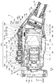
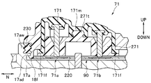
次に、図2~図4を用いて上述したカメラヘッド3の具体的な構成を説明する。図2は、図1のカメラヘッドを示す斜視図、図3は、図2中のIII-III線に沿うカメラヘッドの部分断面図、図4は、図3のカメラヘッドにおけるIV線にて囲った部位を拡大して示す部分断面図である。
図2、図3に示すように、カメラヘッド3は、カプラ部15と、該カプラ部15に先端が固定された外装部材17とを有して主要部が構成されている。
図3に示すように、カプラ部15は、内視鏡2のアイピース9が接続される部材であり、外装部材17の先端17ak側の外周に対して、固定ネジ32が用いられて固定されている。
外装部材17は、内部を気密に保持するとともに金属から1層に構成されており、メインカバー17aと、該メインカバー17aの基端に、半田、溶接等により水密気密に固定されたリヤカバー17bとから構成されている。即ち、外装部材17は、気密ケースを兼ねている。
尚、外装部材17を構成する金属としては、軽量化を図るため、例えばチタンが挙げられる。また、外装部材17を構成する金属としては、軽量かつ熱伝導率の低いものが望ましい。
しかしながら、上述したオートクレーブ処理における高温高圧蒸気の内部17iへの進入を防ぐために行う気密溶接ができる金属であれば、ステンレス等どのようなものであっても構わない。
また、図2に示すように、メインカバー17aの外表面17agの一側面、具体的には、図2に示す図中上部の外表面17agに、被検体内の像の撮像操作に用いられるスイッチユニット270がカメラヘッド3の長手方向Nに沿って固定されている。尚、スイッチユニット270の詳しい構成は、後述する。
また、図3に示すように、外装部材17によって気密に封止された内部17iに、撮像ユニット100を有する内部ユニット150が設けられている。
撮像ユニット100は、複数のレンズ30と、該レンズ30を保持するレンズ枠51と、撮像素子33と、各種基板等の電気部品を具備して主要部が構成されている。
より具体的には、図3に示すように、複数のレンズ30は、メインカバー17aの先端17ak内に、外周がメタライズ化されることにより半田等によって気密に固定された観察窓31に対して長手方向Nに対向して位置している。
尚、観察窓31は、カメラヘッド3のカプラ部15に、内視鏡2のアイピース9が接続された際、アイピース9内のレンズに対して、長手方向Nにおいて対向して位置する。
また、外装部材17の内部17iにおいて、観察窓31の後方に、レンズ枠51によって保持された複数のレンズ30が設けられており、該複数のレンズ30の結像位置に、撮像素子33が位置している。
尚、レンズ枠51及び撮像素子33は、長手方向Nにおいてレンズ枠51と撮像素子33との間に設けられた固定枠120に保持されている。
固定枠120は、内部ユニット150を保持するものであり、撮像素子33の熱を逃がすため金属から構成されている。
また、固定枠120は、図3に示すように、内部ユニット150をメインカバー17aの内面17nに固定する図示しない1つまたは複数の固定部位120yを有している(図3においては、固定部位120yは1つのみ図示)。
尚、固定部位120yに、長手方向Nに貫通する図示しない貫通孔が形成されており、貫通孔に挿通されたネジ60が、該ネジ60の外周に被覆された図示しないワッシャを介して内面17nに形成されたネジ穴16に螺合される。このことにより、固定部位120yは内面17nに、金属を介して固定される。即ち、固定枠120は、内面17nに固定される。
さらに、図3に示すように、外装部材17の内部17iにおいて、撮像素子33の後方に、L字状に折り曲げられた基板フォルダ200に保持されるとともに撮像素子33に電気的に接続された各種基板が設けられている。
各種基板は、基板フォルダ200の後方に位置する基板35に、U字状に折り曲げられたフレキシブル基板138を介して電気的に接続されている。
基板フォルダ200及び基板35は、固定枠120の外周に固定されたフレーム28に固定されている。
基板35に、フレキシブル基板138とは上下逆さのU字状に折り曲げられて基板35から延出されたフレキシブル基板38のコネクタ38aが電気的に接続されている。
また、フレキシブル基板38の延出端に設けられたコネクタ38bは、基板35よりも後方において傾いて設けられた基板320に電気的に接続されている。
基板320の基端側には、リヤカバー17bの端部の内面17nに対して溶接等によって固定されたハーメチックコネクタ160が設けられており、該ハーメチックコネクタ160の基端側には、基板45が設けられている。
ハーメチックコネクタ160には、該ハーメチックコネクタ160を貫通する導通ピン42が複数設けられており、導通ピン42により基板320と基板45とは電気的に接続されている。
また、図3に示すように、リヤカバー17bの基端側に、金属から構成されたケーブル固定枠41の先端が、ハーメチックコネクタ160を介して接続されている。
さらに、ケーブル固定枠41の基端に、スペーサリング179が固定されており、スペーサリング179の内周面には、カメラケーブル12の先端が接続されている。
カメラケーブル12の内部には、金属の導体の外周に、例えば樹脂材料から構成された複数の電気コードが収納されており、該電気コードの先端は、ケーブル固定枠41内まで延出され、基板45に電気的に接続されている。
また、カメラケーブル12の外周面には、カメラケーブル12の急激な屈曲を防止する折れ止め44が被覆されている。また、折れ止め44の外周には、リヤネジ50が移動自在に被覆されており、リヤネジ50により、カメラケーブル12の先端側が、ケーブル固定枠41に水密気密に固定される。
さらに、リヤカバー17bの先端から、リヤネジ50の先端まで、リヤカバー17bの外周及びケーブル固定枠41の基端側の外周を覆うように、レーデル(登録商標)やPEEK等の樹脂材料から構成された外装カバー40が設けられている。
次に、スイッチユニット270の構成を、図2~図4を用いて説明する。
図2~図4に示すように、メインカバー17aの図中上部の外表面17agに、所定の大きさを有するとともに、図中UP-DOWN方向に所定の深さを有し、周囲をメインカバー17aの上部側の外表面17agからUP方向に起立する壁部17awに覆われた開口部90が形成されている。
尚、開口部90は、外装部材17の内部17iには連通しておらず、メインカバー17aの上部外表面17agが、開口部90の底部を構成している。
開口部90に、スイッチユニット270が嵌入されて水密的に固定されている。
図3に示すように、スイッチユニット270は、複数のスイッチボタン71~75と、該複数のスイッチボタン71~75を開口部90に水密部材230を介して水密的に取り付ける枠体であるスイッチボタン枠18と、基板220とを具備して主要部が構成されている。
スイッチボタン71は、レンズ30の一部を前後に移動させて焦点調整を行うとともに近点ボタンと遠点ボタンとが1つに一体化された焦点調節ボタンである。
スイッチボタン71は、遠点スイッチ71aと、該遠点スイッチ71aから長手方向Nに離間して設けられた近点スイッチ71bと、遠点スイッチ71a及び近点スイッチ71bを開口部90に固定するとともに水密確保用のスイッチ固定部材271とを具備している。
また、スイッチボタン71は、遠点スイッチ71a、近点スイッチ71b及びスイッチ固定部材271を覆う柔軟な1つのスイッチカバー171を具備している。
スイッチボタン72は、レンズ30の一部を前後に移動させて焦点倍率を調整するとともにWideボタンとTeleボタンとが1つに一体化されたズームボタンである。
スイッチボタン72は、図示しないWideスイッチと、該Wideスイッチから長手方向Nに略直交する方向に離間して設けられた図示しないTeleスイッチと、Wideスイッチ及びTeleスイッチを開口部90に固定するとともに水密確保用のスイッチ固定部材272とを具備している。
また、スイッチボタン72は、Wideスイッチ、Teleスイッチ及びスイッチ固定部材272を覆う柔軟な1つのスイッチカバー172を具備している。
スイッチボタン73は、明るさ調整ボタンであり、図示しないスイッチと、該スイッチを開口部90に固定するとともに水密確保用の図示しないスイッチ固定部材と、スイッチ及びスイッチ固定部材を覆う柔軟な1つの図示しないスイッチカバー173(図示されず)とを具備して主要部が構成されている。
スイッチボタン74は、色調整ボタンであり、図示しないスイッチと、該スイッチを開口部90に固定するとともに水密確保用の図示しないスイッチ固定部材と、スイッチ及びスイッチ固定部材を覆う柔軟な1つの図示しないスイッチカバー174(図示されず)とを具備して主要部が構成されている。
尚、スイッチカバー174は、スイッチボタン74用のスイッチ固定部材の外周に締め付けられて嵌合されている。
スイッチボタン75は、レリーズボタンであり、スイッチ75aと、該スイッチ75aを開口部90に固定するとともに水密確保用のスイッチ固定部材275と、スイッチ75a及びスイッチ固定部材275を覆う柔軟な1つのスイッチカバー175とを具備して主要部が構成されている。
尚、スイッチカバー175は、スイッチ固定部材275の外周に締め付けられて嵌合されている。
スイッチボタン枠18は、例えば樹脂から構成されており、スイッチボタン71~75の各種スイッチカバー171~175のUP方向側が露出されるようDOWN方向側の一部を覆うとともに、各種スイッチカバー171~175が水密的に固定されている。
一例を挙げると、図4に示すように、スイッチカバー171のDOWN方向側の底部の外周に設けられた外向フランジ171fが、スイッチボタン枠18に係止されたスイッチボタン71の嵌入孔18hのDOWN側の底部の開口端に係止される。
このことにより、スイッチカバー171は、スイッチボタン枠18に水密的に固定されている。尚、以上のスイッチカバー171の水密構成は、各種スイッチカバー172~175においても同様である。
スイッチボタン枠18は、図4に示すように、各種スイッチカバー171~175の被覆部の外周面が、壁部17awの内周面に、周状の水密部材230を介して水密的に当接されている。
また、スイッチボタン枠18は、開口部90に水密的に固定されている。具体的には、スイッチボタン枠18は、被覆部に設けられたDOWN方向側における底部の外周において外周方向に設定間隔を有して複数設けられた弾性変形可能な爪部18f(図4では、爪部18fは、1つのみ図示)が、壁部17awから開口部90の内側に突出して設けられた係止突起17adにスナップフィットにて係止されている。
さらに、スイッチボタン枠18は、メインカバー17aの上部側の外表面17agに対して、1つのネジ19によって固定されている。このことにより、スイッチボタン枠18は、開口部90に水密的に固定されている。
基板220は、後述するハーメチックコネクタ310(図11参照)を介して、外装部材17の内部17iに設けられるとともに基板フォルダ200に保持された基板に電気的に接続されている。
ここで、遠点スイッチ71aと近点スイッチ71bとの間に、スイッチ固定部材271に対するスイッチカバー171の係止部が設けられている。
これは、係止部により、オートクレーブ処理等によるスイッチカバー171内の陰陽圧により、例えばスイッチボタン71における遠点スイッチ71aと近点スイッチ71bとの間の位置におけるスイッチカバー171の浮き沈みを防止するためである。
具体的には、図4に示すように、係止部は、スイッチカバー171において、遠点スイッチ71aと近点スイッチ71bとの間の位置からスイッチ固定部材271に向けてDOWN方向に突設される凸状の爪部171tから構成されている。
爪部171tは、スイッチ固定部材271において爪部171tに対向する位置にUP-DOWN方向に貫通するよう形成された貫通孔271hをUP-DOWN方向に貫通してスイッチ固定部材271に係止される。
この爪部171tのスイッチ固定部材271に対する係止によって、スイッチカバー171内の陰陽圧により、例えばスイッチボタン71における遠点スイッチ71aと近点スイッチ71bとの間の位置におけるスイッチカバー171の浮き沈みが防止される。
また、スイッチボタン72におけるWideスイッチとTeleスイッチとの間の位置におけるスイッチカバー172の浮き沈みも、スイッチ固定部材272に設けられた係止部である凸状の爪部172tにより防止されている。
尚、爪部172tの形状及び係止構成は、爪部171tの形状及び係止構成と同様である。
尚、その他のカメラヘッド3の構成は周知であるため、その説明は省略する。
このように、本実施の形態においては、スイッチボタン71は、レンズ30の一部を前後に移動させて焦点調整を行うとともに近点ボタンと遠点ボタンとが1つに一体化された焦点調節ボタンであると示した。
また、スイッチボタン72は、レンズ30の一部を前後に移動させて焦点倍率を調整するとともにWideボタンとTeleボタンとが1つに一体化されたズームボタンであると示した。
さらに、スイッチボタン71における遠点スイッチ71aと近点スイッチ71bとの間に、スイッチ固定部材271に対するスイッチカバー171の係止部が設けられていると示した。
具体的には、係止部は、スイッチカバー171において、遠点スイッチ71aと近点スイッチ71bとの間の位置からスイッチ固定部材271に向けてDOWN方向に突設される凸状の爪部171tから構成されていると示した。
また、爪部171tは、スイッチ固定部材271に形成された貫通孔271hを介してスイッチ固定部材271に係止されると示した。
このことによれば、スイッチカバー171に設けられた爪部171tのスイッチ固定部材271に対する係止により、近点ボタンと遠点ボタンとが一体化されスイッチボタン71の表面積が大きくなっていたとしても、カメラヘッド3のオートクレーブ処理の際におけるスイッチカバー171内の陰陽圧による、スイッチボタン71における遠点スイッチ71aと近点スイッチ71bとの間の位置におけるスイッチカバー171の浮き沈みを防止することができる。
同様に、スイッチボタン72におけるWideスイッチとTeleスイッチとの間に、スイッチ固定部材272に対するスイッチカバー172の係止部である凸状の爪部172tが設けられていると示した。
このことによれば、スイッチボタン71と同様に、スイッチカバー172に設けられた爪部172tのスイッチ固定部材272に対する係止により、WideボタンとTeleボタンとが一体化されスイッチボタン72の表面積が大きくなっていたとしても、カメラヘッド3のオートクレーブ処理の際におけるスイッチカバー172内の陰陽圧による、スイッチボタン72におけるWideスイッチとTeleスイッチとの間の位置におけるスイッチカバー172の浮き沈みを防止することができる。
以上から、水密的に保持されたスイッチカバーの内部の陰陽圧により、複数のスイッチを覆うスイッチカバーのスイッチ間の浮き沈みを防止する構成を具備するスイッチユニット270、該スイッチユニット270を備えたカメラヘッド3、該スイッチユニット270を備えた内視鏡2を提供することができる。
尚、以下、変形例を、図5を用いて示す。図5は、図4の係止部が、スイッチ固定部材に設けられている変形例を示す部分断面図である。
上述した本実施の形態においては、スイッチボタン71における遠点スイッチ71aと近点スイッチ71bとの間に、スイッチ固定部材271に対するスイッチカバー171の係止部が設けられていると示した。
また、係止部は、スイッチカバー171において、遠点スイッチ71aと近点スイッチ71bとの間の位置からスイッチ固定部材271に向けてDOWN方向に突設される凸状の爪部171tから構成されていると示した。
これに限らず、図5に示すように、スイッチボタン71における係止部は、スイッチ固定部材271において、スイッチカバー171に向けてUP方向側に突設されるとともに、スイッチカバー171に形成された凹溝171mに係止される凸状の爪部271tから構成されていても構わない。
尚、図示しないが、同様に、スイッチボタン72における係止部も、スイッチ固定部材272において、スイッチカバー172に向けてUP方向側に突設されるとともに、スイッチカバー172に形成された凹溝に係止される凸状の爪部から構成されていても構わない。
このような構成によっても、上述した本実施の形態と同様の効果を得ることができる。
また、以下、別の変形例を、図6を用いて示す。図6は、図4、図5の係止部が、シーソ型ボタンに適用された変形例を示す部分断面図である。
図4、図5に示したスイッチ固定部材271に対するスイッチカバー171の係止部は、スイッチボタン71がシーソ型ボタン構造を有している場合においても適用可能である。
具体的には、図6に示すように、基板220に接触する支点371sを基に、方向Bまたは方向Cにスイッチカバー171を介して傾倒操作されるスイッチ端子371において、スイッチカバー171に接触する部位における図6中A線で囲った部位に、図4、図5に示した係止部を適用しても、上述した本実施の形態と同様の効果を得ることができる。
尚、図6のシーソ型ボタンの構成は、スイッチボタン72に対しても適用可能であることは云うまでもない。
さらに、上述した本実施の形態においては、スイッチボタン71、72は、それぞれ2つのスイッチを有している場合を例に挙げて示したが、これに限らず、3つ以上のスイッチを有している場合においても適用可能であることは勿論である。
図7は、図3のスイッチボタン枠の爪部の形状の変形例を、メインカバーの一部とともに示す部分断面図、図8は、図3のスイッチボタン枠の爪部の図7とは異なる形状の変形例を示す部分断面図である。
通常、スイッチユニット270の開口部90に対する組立性を考慮すると、事前にスイッチボタン71~75が嵌入孔18hに組み込まれたスイッチボタン枠18を、開口部90にネジ19にて固定する手法が好ましい。
しかしながら、スイッチボタン枠18の開口部90に対する水密性を向上させるには、ネジ19の本数を増やさなければならず、外観を損なうといった問題があった。
さらに、スイッチボタン枠18の外周形状が複雑になると、ネジ19を用いたスイッチボタン枠18の固定では、周状に設けられた水密部材230に対しスイッチボタン枠18から均等に圧力が加わらない。
よって、開口部90に対するスイッチボタン枠18の水密性を確保することが難しくなってしまうといった問題もあった。
そこで、上述した本実施の形態においては、開口部90に対するスイッチボタン枠18の固定には、ネジ19は1本しか用いていない。
さらに、上述したように複数の爪部18fを、壁部17awから開口部90の内側に突出して設けられた係止突起17adにスナップフィットにて係止させる構成を用いている。
このような複数の爪部18fを用いる構成においては、ネジ19を1本しか用いなくても係止突起17adに対する複数の爪部18fの係止により周状の水密部材230に対してスイッチボタン枠18から均等に圧力を加えることができる。
さらに、ネジ19は1本しか用いないばかりか複数の爪部18fは外表面に露出されないことから、カメラヘッド3のデザイン性を向上させることができる。
このような複数の爪部18fを用いる構成において、図7に示すように、各爪部18fの係止部18pの係止突起17adに対する接触面18ps及び係止突起17adにおける係止部18pの接触面17adsに、それぞれ角度θの傾斜面が形成されていても良い。
このことによれば、係止部18pを係止突起17adに係止させるため、接触面17adsに対して接触面18psを接触させてDOWN方向に通過する際、接触面17adsに対する接触面18psの滑り性が向上されることから、通過性を向上させることができる。
また、図8に示すように、各爪部18fのUP方向の上部の付け根に、円弧状の凹み18fnが形成されておれば、係止部18pを係止突起17adに係止させる際、爪部18fが撓みやすくなる。即ち、弾性変形しやすくなる。
尚、凹み18fnの円弧の半径Rは、大きい程、爪部18fが撓む際の応力を緩和することができる。
さらに、係止部18pの係止突起17adに係止される部位18pkの円弧は、爪部18fの径を考慮すると大きな半径に形成することが出来ないことから、図8に示すように、係止部18pにリブ18prが形成されていても構わない。
図9は、図3の組み付け前の水密部材の形状の変形例を、スイッチボタン枠及びメインカバーの一部とともに示す部分断面図、図10は、図9の水密部材を組み付けた後の状態を、スイッチボタン枠及びメインカバーの一部とともに示す部分断面図である。
上述した図3に示すように、開口部90に対してスイッチボタン枠18は、水密部材230を介して水密的に組み付けられている。
尚、水密部材230としては、水密性を向上させるため、図9、図10に示すように、外周に複数の突起230dが形成されることにより潰しシロが大きく設定された断面略矩形状の構成が周知である。
このような外周に複数の突起230dを有する水密部材230において、本構成においては、図9に示すように、突起230dに傾斜面230dkが形成されている。
この傾斜面230dkにより、水密部材230をDOWN方向に潰して開口部90にスイッチボタン枠18を組み付ける際の水密部材230の通過抵抗が減少するため、水密部材230の挿入性を向上させることができる。
また、各突起230dが潰れやすくなることから、従来よりも小さな力で開口部90にスイッチボタン枠18を組み付けることができる。
さらに、本構成においては、水密部材230の突起230dにおいて、開口部90にスイッチボタン枠18を組み付けた際に発生するとともに外観に露出される隙間Sに対向する位置に、リブ230rが形成されている。
このことによれば、図10に示すように、開口部90にスイッチボタン枠18が組み付けられた後、リブ230rは潰されて隙間Sが埋まることから、隙間S付近の洗浄消毒性を向上させることができる。
図11は、図3中のXI線で囲った従来のハーメチックコネクタの固定構成を概略的に示す部分断面図、図12は、本構成のハーメチックコネクタの固定構成を概略的に示す部分断面図である。
上述した本実施の形態に示したように、スイッチユニット270の基板220は、ハーメチックコネクタ310を介して、外装部材17の内部17iの基板フォルダ200に固定された基板に電気的に接続されていると示した。
尚、ハーメチックコネクタ310の固定方法及び構成としては、図11に示すように、メインカバー17aの上部側において開口部90に連通する部位に開口部90と内部17iとが連通するよう形成された挿通孔17ahの段部17apに、リング状の半田309を介してハーメチックコネクタ310の段部310pを付き当てる。
その後、半田309を溶かして、段部310pが段部17apに突き当たる位置までハーメチックコネクタ310をDOWN方向に落とし込んで気密封止する手法、構成が周知である。
しかしながら、このような手法及び構成においては、段部310pが段部17apに完全に突き当たるまでハーメチックコネクタ310が落とし込まれず途中で止まってしまう場合があった。
さらに、ハーメチックコネクタ310が傾いた状態で気密封止されてしまう場合が有った。よって、ハーメチックコネクタ310の封止品質(強度、気密性)が劣化してしまう場合があった。
このような事情に鑑み、本構成においては、図12に示すように、段部310pを段部17apに付き当てた後、段部310pの外周を挿通孔17ahに対してリング状の半田309を用いて固定する手法及び構成を用いた。
このような構成によれは、半田309が溶解しても、段部17apに対する段部310pの付き当て状態は変化しない。
このことから、ハーメチックコネクタ310が傾いたり、ハーメチックコネクタ310のUP-DOWN方向における位置が変化したりしてしまうことがない。
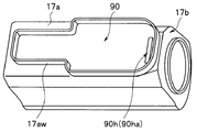
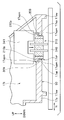
図13は、前側封止型の図3の外装部材の斜視図、図14は、図13の気密ケースの開口部からのハーメチックコネクタを用いない基板の引き出し構成を示す斜視図、図15は、図14のメインカバーにフロントカバーが固定された状態における図14中のXV-XV線に沿う部分断面図である。
上述した本実施の形態においては、外装部材17は、メインカバー17aの基端側をリヤカバー17bにて封止することにより、内部17iを水密気密に封止すると示した。
これに限らず、図15に示すように、図13に示すメインカバー17aの先端側をフロントカバー17cにて封止することにより、内部17iを水密気密に封止する構成も考えられる。
このような構成において、ハーメチックコネクタ310を用いずに、開口部90から基板220を後方側に引き出し、フレキシブルな延長基板221を用いてハーメチックコネクタ160の導通ピン42に電気的に接続する構成が考えられる。
しかしながら、この構成では、開口部90からハーメチックコネクタ160に亘って基板220及び延長基板221が外観に露出される面積が大きくなるばかりか、外観形状が複雑になる。
このため、スイッチユニット270の水密性の確保が難しくなってしまうといった問題があった。
そこで、上述した本実施の形態や、図13に示すように、開口部90を壁部17awにて覆うことにより、水密性の確保を開口部90のみとすることにより、外観形状を簡易化し、スイッチユニット270の水密性を容易に確保する構成が考えられる。
このような構成において、ハーメチックコネクタ310を用いずに、基板220を導通ピン42に接続する構成として、図13~図15に示す構成が考えられる。
具体的には、メインカバー17aに、一端が開口部90に開口90haとして開口され、他端がメインカバー17aの基端を封止するリヤカバー17bに開口90hbとして開口される傾斜孔90hが形成され、傾斜孔90hを介して延長基板221を開口部90から引き出す構成が考えられる。
このような構成によれば、基板220の延長基板221を、傾斜孔90hを介して開口部90外におけるリヤカバー17bの後方に引き出し、導通ピン42に電気的に接続することができる。
このことから、ハーメチックコネクタ310を用いる場合と同様の、スイッチユニット270の水密性を確保することができる。
図16は、図3のメインカバーに対するハーメチックコネクタの固定方法を概略的に示す部分断面図、図17は、図16のメインカバーの挿通孔を、段部を用いない形状に形成した変形例を、ハーメチックコネクタとともに示す部分断面図である。
上述した図11、図12に示すように、メインカバー17aの挿通孔17ahに対して、ハーメチックコネクタ310は、半田309を介して固定される。
また、図3に示すように、ハーメチックコネクタ310は、メインカバー17aのUP方向側に固定されている。
しかしながら、ハーメチックコネクタ310をUP方向側に向けた状態において、UP方向から半田309を用いたハーメチックコネクタ310の固定を行うと、ハーメチックコネクタ310の自重により、半田309とともに用いる既知のフラックスが内部17iに進入しやすくなってしまう。
その結果、内部17iが腐食してしまう可能性があることから、半田固定後、内部17iのフラックスを拭き取る必要があるが、内部17iに漏れたフラックスは拭き取り難いといった問題があった。
そこで、図16に示すように、挿通孔17ahに対してハーメチックコネクタ310を、半田309を用いて固定する際、外装部材17をUP-DOWN方向において上下逆さまにし、内部17i側から固定治具341を用いてハーメチックコネクタ310を、半田309を溶解するホットプレート340に付勢して固定しても良い。
尚、この際、挿通孔17ahの周状の開口端17apmに傾斜面が形成されておれば、半田溜まりが目視可能となることから、半田接合性が良好か否かを作業者は容易に視認することができる。
また、ホットプレート340と半田309の距離が近接するため、ホットプレート340からの半田309への伝熱性が向上する。
さらに、フラックスは、内部17iでは無く、開口部90側に漏れるため、内部17iへのフラックスの進入量を低減させることができる他、フラックスの拭き取り性が向上する。
尚、図17に示すように、挿通孔17ahを段部17ap無しの形状とし、ハーメチックコネクタ310の段部310pが内部17iにおける挿通孔17ahの開口端付近に当接される構成を用いても良い。
図18は、図3のスイッチボタン枠の外周面に周状の水密部材が設けられた構成を、メインカバーの一部とともに概略的に示す部分断面図、図19は、図18の水密部材が、スイッチボタン枠の底面に設けられた構成を概略的に示す部分断面図、図20は、図19の水密部材が、スイッチボタン枠の外周面と底面とを結ぶ傾斜面に設けられた構成を概略的に示す部分断面図、図21は、図20の水密部材を断面L字状に形成した変形例の構成を概略的に示す部分断面図である。
図18に示すように、スイッチボタン枠18を開口部90に組み付けて固定する際、水密部材230がスイッチボタン枠18の外周面に形成されていると、水密部材230が潰れ難く圧入し難いといった問題があった。
また、図19に示すように、水密部材230がスイッチボタン枠18の底面に形成されていると、水密部材230の圧縮反力により、スイッチボタン枠18が反りやすいといった問題があった。
そこで、図20に示すように、水密部材230が、スイッチボタン枠18の外周面と底面とを結ぶ傾斜面18qに形成されていても構わない。
このような構成によれば、水密部材230も断面テーパ状を有することから、圧入の際の抵抗が少なくなるばかりか、スイッチボタン枠18をDOWN方向に押し込む際に、傾斜面18qを用いた楔効果により水密部材230が潰れやすくなる。
よって、取り付け性が良く、傾斜面18qにて水密性を確保することができるため、水密性の高い水密部材230を提供することができる。
尚、図21に示すように、水密部材230は、傾斜面18qから底面側まで延長された断面L字状に形成されていても構わない。
このような構成によれば、開口部90にスイッチボタン枠18を組み付けた際の、壁部17awとスイッチボタン枠18の面合わせ精度の許容量Eを大きく確保することができる。
図22は、図3のスイッチボタン枠の爪部の形状の変形例を示す斜視図である。
上述した本実施の形態においては、スイッチボタン枠18は、複数設けられた弾性変形可能な爪部18fが、係止突起17adにスナップフィットにて係止されると示した。
さらに、メインカバー17aの上部側の外表面17agに対して、1つのネジ19によって固定されることにより、スイッチボタン枠19は、開口部90に水密的に固定されていると示した。
この複数の爪部18fの内、ネジ19から最も離れた位置、例えばスイッチボタン枠18の先端位置の爪部18fが、スイッチボタン枠18の外周方向に大きく形成され、弾性変形することの無い、剛体の爪部18vに形成されていても構わない。尚、爪部18vは、係止突起17adに対して引っ掛かっているのみである。
このような構成によれば、爪部を全て弾性変形可能なものから構成する場合よりも、ネジ19から最も離れた位置の爪部を剛体の爪部18vとすることにより、ネジ19を1本のみ用いる構成においても、よりスイッチボタン枠18の固定強度が向上する。即ち、スイッチボタン枠18の外力による耐性が向上する。
また、剛体の爪部18vを、弾性変形可能な複数の爪部18fと併用することによって、スイッチボタン枠18の取り付け後、簡単にスイッチボタン枠18が外れない構造を提供することができる。
図23は、図3の金リング用の水密部材を示す斜視図、図24は、図23の金リングを示す斜視図である。
図3に示すように、外装カバー40の先端側の内周は、リヤカバー17bの先端側の外周に対して周状の水密部材252を介して水密的に固定されている。
また、外装カバー40の先端側の外周において、外装カバー40の先端と、メインカバー17aの基端との間の位置に、カメラヘッドの機能等を操作者に視覚的に認識させる指標である既知の金リング250が設けられている。
尚、図3に示すように、金リング250とメインカバー17aの基端との間の隙間の洗浄消毒性を向上させるため、該隙間にさらに周状の水密部材251が設けられた構成も周知である。
しかしながら、カメラヘッド3の外周形状が、デザイン性を考慮して流線形を有する複雑な形状を有している場合、水密部材251が回転方向にずれてしまうと、水密性の確保が難しくなってしまう。さらに、水密部材251の一部が外側にはみ出てしまったりする等の問題があった。
このような問題に鑑み、図23に示すように、水密部材251の一部に係止突起251tが設けられ、図24に示すように、金リング250に係止突起251tが係止される係止溝250mが形成されていても構わない。
このような構成によれば、係止溝250mに対する係止突起251tの係止により、水密部材251の回転方向のずれが防止される。このことから、水密部材251の水密性を十分確保できる他、水密部材251のはみ出しを防止することができる。
尚、金リング250に係止突起が設けられ、水密部材251に係止溝が設けられる構成でも同様の効果を得ることができる。
尚、上述した本実施の形態においては、スイッチユニット270は、カメラヘッド3に用いると示したが、これに限らず、内視鏡2単体に用いても良いことは云うまでもない。
本出願は、2016年2月3日に日本国に出願された特願2016-018118号を優先権主張の基礎として出願するものであり、上記の内容は、本願明細書、請求の範囲、図面に引用されたものである。
Claims (7)
- 外装部材の外表面に設けられた開口部においてそれぞれ離間して設けられた複数のスイッチと、
前記開口部に設けられた、前記複数のスイッチを前記開口部に固定するスイッチ固定部材と、
前記複数のスイッチ及び前記スイッチ固定部材を覆うとともに、前記開口部に水密的に固定される柔軟な1つのスイッチカバーと、
各前記スイッチ間に形成された、前記スイッチ固定部材に対する前記スイッチカバーの係止部と、
を具備することを特徴とするスイッチユニット。 - 前記係止部は、前記スイッチカバーに設けられた、前記スイッチ固定部材に向けて突設されるとともに前記スイッチ固定部材に係止される凸状の爪部であることを特徴とする請求項1に記載のスイッチユニット。
- 前記係止部は、前記スイッチ固定部材に設けられた、前記スイッチカバーに向けて突設されるとともに前記スイッチカバーに係止される凸状の爪部であることを特徴とする請求項1に記載のスイッチユニット。
- 前記スイッチカバーは、一部が枠体に覆われており、
前記枠体における前記スイッチカバーの被覆部は、前記開口部に対して水密部材を介して水密的に固定されていることを特徴とする請求項1~3のいずれか1項に記載のスイッチユニット。 - 前記外装部材は、1層の金属から構成されていることを特徴とする請求項1~4のいずれか1項に記載のスイッチユニット。
- 請求項1~5のいずれか1項に記載のスイッチユニットを備えることを特徴とする内視鏡用撮像装置。
- 請求項1~5のいずれか1項に記載のスイッチユニットを備えることを特徴とする内視鏡。
Priority Applications (3)
| Application Number | Priority Date | Filing Date | Title |
|---|---|---|---|
| JP2017530778A JPWO2017134883A1 (ja) | 2016-02-02 | 2016-10-31 | スイッチユニット、該スイッチユニットを備えた内視鏡用撮像装置、該スイッチユニットを備えた内視鏡 |
| CN201680080745.0A CN108601503B (zh) | 2016-02-02 | 2016-10-31 | 开关单元、具有该开关单元的内窥镜用摄像装置以及具有该开关单元的内窥镜 |
| US16/048,454 US10534169B2 (en) | 2016-02-02 | 2018-07-30 | Switch unit, image pickup apparatus for endoscope including switch unit, and endoscope including switch unit |
Applications Claiming Priority (2)
| Application Number | Priority Date | Filing Date | Title |
|---|---|---|---|
| JP2016018118 | 2016-02-02 | ||
| JP2016-018118 | 2016-02-02 |
Related Child Applications (1)
| Application Number | Title | Priority Date | Filing Date |
|---|---|---|---|
| US16/048,454 Continuation US10534169B2 (en) | 2016-02-02 | 2018-07-30 | Switch unit, image pickup apparatus for endoscope including switch unit, and endoscope including switch unit |
Publications (1)
| Publication Number | Publication Date |
|---|---|
| WO2017134883A1 true WO2017134883A1 (ja) | 2017-08-10 |
Family
ID=59500106
Family Applications (1)
| Application Number | Title | Priority Date | Filing Date |
|---|---|---|---|
| PCT/JP2016/082324 Ceased WO2017134883A1 (ja) | 2016-02-02 | 2016-10-31 | スイッチユニット、該スイッチユニットを備えた内視鏡用撮像装置、該スイッチユニットを備えた内視鏡 |
Country Status (4)
| Country | Link |
|---|---|
| US (1) | US10534169B2 (ja) |
| JP (2) | JPWO2017134883A1 (ja) |
| CN (1) | CN108601503B (ja) |
| WO (1) | WO2017134883A1 (ja) |
Families Citing this family (3)
| Publication number | Priority date | Publication date | Assignee | Title |
|---|---|---|---|---|
| JP6906987B2 (ja) | 2017-03-10 | 2021-07-21 | ソニー・オリンパスメディカルソリューションズ株式会社 | 内視鏡用カメラヘッド |
| WO2020067104A1 (ja) | 2018-09-27 | 2020-04-02 | 富士フイルム株式会社 | 内視鏡 |
| JP7602945B2 (ja) | 2021-03-19 | 2024-12-19 | ソニー・オリンパスメディカルソリューションズ株式会社 | 内視鏡用撮像装置及び撮像システム |
Citations (5)
| Publication number | Priority date | Publication date | Assignee | Title |
|---|---|---|---|---|
| JPH08112243A (ja) * | 1994-10-13 | 1996-05-07 | Olympus Optical Co Ltd | カバー式内視鏡 |
| JP2002170453A (ja) * | 2000-11-30 | 2002-06-14 | Asahi Optical Co Ltd | 押しボタンスイッチ及び内視鏡の押しボタンスイッチ |
| JP2004267342A (ja) * | 2003-03-06 | 2004-09-30 | Olympus Corp | 医療機器用スイッチ |
| JP2004337188A (ja) * | 2003-05-12 | 2004-12-02 | Olympus Corp | 流体制御入力手段 |
| JP2013056003A (ja) * | 2011-09-07 | 2013-03-28 | Olympus Medical Systems Corp | 撮像装置、内視鏡 |
Family Cites Families (12)
| Publication number | Priority date | Publication date | Assignee | Title |
|---|---|---|---|---|
| JPS4330993Y1 (ja) * | 1967-11-11 | 1968-12-17 | ||
| JPS53133704U (ja) * | 1977-03-30 | 1978-10-23 | ||
| JPS53133704A (en) * | 1977-04-27 | 1978-11-21 | Toshiba Corp | Supporter for stator core |
| JPS5929082U (ja) * | 1982-08-17 | 1984-02-23 | クラリオン株式会社 | 電子機器のケ−ス |
| JP2644020B2 (ja) * | 1988-12-16 | 1997-08-25 | オリンパス光学工業株式会社 | 内視鏡用スイッチ |
| JPH04169015A (ja) * | 1990-12-20 | 1992-06-17 | Teikoku Tsushin Kogyo Co Ltd | 押釦スイッチのキートップ |
| JP3715809B2 (ja) * | 1998-12-17 | 2005-11-16 | 株式会社東海理化電機製作所 | 防水機能を有する操作装置 |
| JP3579615B2 (ja) * | 1999-05-07 | 2004-10-20 | 富士写真光機株式会社 | 変倍機能を有する内視鏡 |
| JP5147887B2 (ja) * | 2009-04-02 | 2013-02-20 | オリンパスメディカルシステムズ株式会社 | 内視鏡用撮像装置 |
| JP2011147497A (ja) * | 2010-01-19 | 2011-08-04 | Olympus Medical Systems Corp | 撮像ユニット |
| CA2815936A1 (en) * | 2013-03-14 | 2014-09-14 | Stryker Corporation | Tamper-evident camera enclosure |
| JP6551662B2 (ja) * | 2015-06-12 | 2019-07-31 | セイコーエプソン株式会社 | 押しボタン及び押しボタンを含む電子機器 |
-
2016
- 2016-10-31 JP JP2017530778A patent/JPWO2017134883A1/ja active Pending
- 2016-10-31 CN CN201680080745.0A patent/CN108601503B/zh active Active
- 2016-10-31 WO PCT/JP2016/082324 patent/WO2017134883A1/ja not_active Ceased
-
2018
- 2018-02-05 JP JP2018018486A patent/JP6571222B2/ja active Active
- 2018-07-30 US US16/048,454 patent/US10534169B2/en active Active
Patent Citations (5)
| Publication number | Priority date | Publication date | Assignee | Title |
|---|---|---|---|---|
| JPH08112243A (ja) * | 1994-10-13 | 1996-05-07 | Olympus Optical Co Ltd | カバー式内視鏡 |
| JP2002170453A (ja) * | 2000-11-30 | 2002-06-14 | Asahi Optical Co Ltd | 押しボタンスイッチ及び内視鏡の押しボタンスイッチ |
| JP2004267342A (ja) * | 2003-03-06 | 2004-09-30 | Olympus Corp | 医療機器用スイッチ |
| JP2004337188A (ja) * | 2003-05-12 | 2004-12-02 | Olympus Corp | 流体制御入力手段 |
| JP2013056003A (ja) * | 2011-09-07 | 2013-03-28 | Olympus Medical Systems Corp | 撮像装置、内視鏡 |
Also Published As
| Publication number | Publication date |
|---|---|
| JP6571222B2 (ja) | 2019-09-04 |
| JPWO2017134883A1 (ja) | 2018-02-08 |
| JP2018075461A (ja) | 2018-05-17 |
| US20180348502A1 (en) | 2018-12-06 |
| CN108601503B (zh) | 2020-09-29 |
| CN108601503A (zh) | 2018-09-28 |
| US10534169B2 (en) | 2020-01-14 |
Similar Documents
| Publication | Publication Date | Title |
|---|---|---|
| JP4754871B2 (ja) | 内視鏡の先端部 | |
| JP6184655B1 (ja) | 内視鏡用撮像装置 | |
| JP6571222B2 (ja) | 内視鏡用撮像装置および内視鏡 | |
| JP2001212075A (ja) | 内視鏡 | |
| US11644661B2 (en) | Medical image pickup apparatus | |
| JPH10258034A (ja) | 内視鏡用撮像装置 | |
| JP2013056003A (ja) | 撮像装置、内視鏡 | |
| JP6368662B2 (ja) | 内視鏡 | |
| JP5147887B2 (ja) | 内視鏡用撮像装置 | |
| JP2006034543A (ja) | 内視鏡、及びその修理方法 | |
| WO2019026385A1 (ja) | 内視鏡用カメラヘッド | |
| JP6576098B2 (ja) | 医療用カメラ装置 | |
| JP2000070213A (ja) | 内視鏡 | |
| JP5384857B2 (ja) | 内視鏡装置 | |
| JP3279398B2 (ja) | 内視鏡用撮像装置 | |
| JP2011147497A (ja) | 撮像ユニット | |
| JP7504812B2 (ja) | 内視鏡 | |
| JP2016158769A (ja) | 内視鏡 | |
| JP5160020B2 (ja) | 内視鏡装置 | |
| JP3076655B2 (ja) | 内視鏡のライトガイドコネクタ装置 | |
| CN113543693A (zh) | 内窥镜的连接器装置 | |
| JP2002102158A (ja) | 内視鏡撮像システム | |
| JP3863788B2 (ja) | 内視鏡 | |
| JPH10295637A (ja) | 内視鏡用撮像装置 | |
| JP2020127619A (ja) | 医療用撮像装置 |
Legal Events
| Date | Code | Title | Description |
|---|---|---|---|
| ENP | Entry into the national phase |
Ref document number: 2017530778 Country of ref document: JP Kind code of ref document: A |
|
| 121 | Ep: the epo has been informed by wipo that ep was designated in this application |
Ref document number: 16889366 Country of ref document: EP Kind code of ref document: A1 |
|
| NENP | Non-entry into the national phase |
Ref country code: DE |
|
| 122 | Ep: pct application non-entry in european phase |
Ref document number: 16889366 Country of ref document: EP Kind code of ref document: A1 |