WO2017130772A1 - 車両用通信システム、車載機及び携帯機 - Google Patents
車両用通信システム、車載機及び携帯機 Download PDFInfo
- Publication number
- WO2017130772A1 WO2017130772A1 PCT/JP2017/001240 JP2017001240W WO2017130772A1 WO 2017130772 A1 WO2017130772 A1 WO 2017130772A1 JP 2017001240 W JP2017001240 W JP 2017001240W WO 2017130772 A1 WO2017130772 A1 WO 2017130772A1
- Authority
- WO
- WIPO (PCT)
- Prior art keywords
- vehicle
- portable device
- walking
- signal
- locking
- Prior art date
- Legal status (The legal status is an assumption and is not a legal conclusion. Google has not performed a legal analysis and makes no representation as to the accuracy of the status listed.)
- Ceased
Links
Images


Classifications
-
- B—PERFORMING OPERATIONS; TRANSPORTING
- B60—VEHICLES IN GENERAL
- B60R—VEHICLES, VEHICLE FITTINGS, OR VEHICLE PARTS, NOT OTHERWISE PROVIDED FOR
- B60R25/00—Fittings or systems for preventing or indicating unauthorised use or theft of vehicles
- B60R25/20—Means to switch the anti-theft system on or off
- B60R25/24—Means to switch the anti-theft system on or off using electronic identifiers containing a code not memorised by the user
-
- B—PERFORMING OPERATIONS; TRANSPORTING
- B60—VEHICLES IN GENERAL
- B60R—VEHICLES, VEHICLE FITTINGS, OR VEHICLE PARTS, NOT OTHERWISE PROVIDED FOR
- B60R25/00—Fittings or systems for preventing or indicating unauthorised use or theft of vehicles
- B60R25/01—Fittings or systems for preventing or indicating unauthorised use or theft of vehicles operating on vehicle systems or fittings, e.g. on doors, seats or windscreens
-
- B—PERFORMING OPERATIONS; TRANSPORTING
- B60—VEHICLES IN GENERAL
- B60R—VEHICLES, VEHICLE FITTINGS, OR VEHICLE PARTS, NOT OTHERWISE PROVIDED FOR
- B60R25/00—Fittings or systems for preventing or indicating unauthorised use or theft of vehicles
- B60R25/30—Detection related to theft or to other events relevant to anti-theft systems
- B60R25/31—Detection related to theft or to other events relevant to anti-theft systems of human presence inside or outside the vehicle
Definitions
- the present invention relates to a vehicle communication system, an in-vehicle device, and a portable device.
- This application claims priority based on Japanese Patent Application No. 2016-13702 filed on Jan. 27, 2016, and incorporates all the content described in the Japanese application.
- a vehicle communication system that locks and unlocks a vehicle door without using a mechanical key has been put into practical use.
- a Smart Entry (registered trademark) system that unlocks a vehicle door simply by a user holding a portable device approaching the vehicle or simply grasping a door handle has been put into practical use.
- a vehicle communication system that starts a vehicle engine without using a mechanical key has been put into practical use.
- a smart start (registered trademark) system that starts an engine simply by a user holding a portable device pressing an engine start switch has been put into practical use.
- WAC walk away closing
- the portable device measures the received signal strength of the LF band position detection signal transmitted from the in-vehicle device, and when the received signal strength decreases, it is determined that the user has moved away from the vehicle, and the vehicle door is There are WAC systems that lock automatically.
- the vehicle communication system includes an in-vehicle device that transmits a position detection signal, and a portable device that receives the position detection signal and transmits a response signal, and the in-vehicle device transmits from the portable device.
- a vehicle communication system that outputs a locking signal instructing locking of a vehicle door according to a reception state of the response signal, wherein the portable device detects a walking state of a user holding the portable device A walking detection unit, and a transmission unit that transmits a walking state signal indicating the walking state of the user detected by the walking detection unit, wherein the vehicle-mounted device includes the response signal transmitted from the portable device and A receiving unit that receives the walking state signal, and a determination unit that determines whether locking is necessary based on the walking state of the user indicated by the walking state signal received by the receiving unit and the reception state of the response signal And in the determination unit If it is determined that Joyo, and an output unit for outputting the locking signal.
- the in-vehicle device is an in-vehicle device that transmits a position detection signal and instructs locking of a vehicle door according to a reception state of a response signal transmitted from a portable device that has received the position detection signal.
- Receiving the response signal transmitted from the portable device and a walking state signal indicating the walking state of the user holding the portable device, and the walking state signal received by the receiving unit Based on the walking state of the user and the reception state of the response signal, a determination unit that determines whether locking is necessary, and a locking signal that instructs locking of the vehicle door when the determination unit determines that locking is necessary
- the portable device is a portable device that receives a position detection signal transmitted from an in-vehicle device and transmits a response signal, and detects a walking state of a user holding itself, A transmission unit that transmits a walking state signal indicating the walking state of the user detected by the walking detection unit.
- the present application can be realized not only as a vehicle communication system, an in-vehicle device, and a portable device including such a characteristic processing unit, but also as a vehicle communication method using such characteristic processing as a step.
- the program can be realized as a program for causing a computer to execute such steps. Also, it may be realized as a semiconductor integrated circuit that realizes part or all of a vehicle communication system, an in-vehicle device and a portable device, or may be realized as another system including a vehicle communication system, an in-vehicle device and a portable device. it can.
- FIG. 1 is a block diagram illustrating a configuration example of a vehicle communication system according to a first embodiment. It is a block diagram which shows one structural example of the vehicle equipment which concerns on Embodiment 1.
- FIG. 1 is a block diagram illustrating a configuration example of a portable device according to a first embodiment.
- 3 is a flowchart illustrating a locking processing procedure according to the first embodiment. It is a conceptual diagram which shows the communication range of a signal for position detection, a response signal, and a walking state signal. It is a conceptual diagram which shows the communication range and walking state signal of the signal for position detection in the condition where a user leaves
- 6 is a block diagram illustrating a configuration example of a portable device according to Embodiment 2.
- FIG. 10 is a flowchart showing a locking processing procedure according to the second embodiment.
- the range in which the portable device can receive the position detection signal in the LF band is about 2 to 3 m in radius centering on the antenna that transmits the position detection signal, and the user holding the portable device has moved away from the vehicle.
- An object of the present application is to provide a vehicle communication system, an in-vehicle device, and a portable device that can determine without error the situation where the portable device moves away from the vehicle and lock the vehicle door.
- a vehicle communication system includes an in-vehicle device that transmits a position detection signal, and a portable device that receives the position detection signal and transmits a response signal.
- a vehicle communication system that outputs a locking signal instructing locking of a vehicle door according to a reception state of the response signal transmitted from a machine, wherein the portable device is a walking of a user holding the portable device
- a walking detection unit that detects a state
- a transmission unit that transmits a walking state signal indicating the walking state of the user detected by the walking detection unit, wherein the in-vehicle device is transmitted from the portable device.
- a receiving unit that receives the response signal and the walking state signal, and determines whether locking is necessary based on the walking state of the user indicated by the walking state signal received by the receiving unit and the reception state of the response signal Determination unit to perform and the determination unit If it is determined that the lock main Te, and an output unit for outputting the locking signal.
- the portable device when the portable device receives the position detection signal transmitted from the in-vehicle device, the portable device transmits a response signal.
- the portable device transmits a walking state signal indicating the walking state of the user holding the portable device.
- the in-vehicle device receives the response signal and the walking state signal transmitted from the portable device.
- the in-vehicle device can determine whether the user is away from the vehicle and the vehicle door needs to be locked based on the user's walking state indicated by the walking state signal in addition to the reception state of the response signal.
- the output unit outputs a locking signal and locks the vehicle door.
- the walking detection unit includes a vibration sensor that detects vibration caused by walking of the user, and the determination unit detects continuous vibration caused by walking of the user, and A configuration is preferable in which it is determined that locking is required when the response signal transmitted from the portable device that has received the position detection signal is not received.
- the vehicle-mounted device can determine that the user is away from the vehicle based on the reception state of the response signal and the continuous vibration caused by the user's walking. Therefore, for example, even when the user moves to a specific position around the vehicle where the portable device cannot receive a position detection signal, the user can move the vehicle if the user is stationary. It is not erroneously determined that the vehicle is away from the vehicle, and the vehicle door is not locked.
- the walking detection unit includes a multi-axis acceleration sensor that detects vibration and linear acceleration due to the user's walking, and the determination unit includes a continuous vibration caused by the user's walking. And the structure which determines that it is required to lock is preferable when the linear acceleration is detected and the response signal transmitted from the portable device that has received the position detection signal is not received.
- the vehicle-mounted device can determine that the user is away from the vehicle based on the reception state of the response signal and the continuous vibration and linear acceleration caused by the user's walking. . Therefore, for example, even when the user moves to a specific position around the vehicle where the portable device cannot receive the position detection signal, the user walks non-linearly, such as around the vehicle. In such a situation, it is not erroneously determined that the user is away from the vehicle, and the vehicle door is not locked.
- the portable device intermittently transmits the walking state signal even after the position detection signal is not received, and the output unit intermittently transmits the determination unit from the portable device.
- a configuration in which the locking signal is output when it is determined that locking is required a plurality of times based on the transmitted walking state signal is preferable.
- the in-vehicle device continuously monitors the reception state of the response signal and the walking state of the user, and when it is determined that the lock is required a plurality of times, outputs the lock signal and opens the vehicle door. Lock. Accordingly, it is possible to more accurately determine the situation in which the portable device held by the user moves away from the vehicle, and lock the vehicle door.
- the vehicle-mounted device transmits a position detection signal, and instructs the vehicle door to be locked according to the reception state of the response signal transmitted from the portable device that has received the position detection signal.
- a reception unit that receives the response signal transmitted from the portable device and a walking state signal indicating a walking state of a user holding the portable device, and the walking state signal received by the receiving unit Based on the walking state of the user and the reception state of the response signal, and a determination unit that determines whether or not locking is necessary, and if the determination unit determines that locking is necessary, instructs the locking of the vehicle door
- An output unit that outputs a locking signal.
- the vehicle-mounted device of this aspect can configure a vehicle communication system that can determine without error the situation in which the portable device moves away from the vehicle and lock the vehicle door.
- the portable device is a portable device that receives the position detection signal transmitted from the in-vehicle device and transmits a response signal, and detects the walking state of the user holding the device. And a transmitter that transmits a walking state signal indicating the walking state of the user detected by the walking detector.
- the portable device of this aspect can constitute a vehicle communication system that can determine without error the situation in which the portable device moves away from the vehicle and lock the vehicle door.
- FIG. 1 is a block diagram illustrating a configuration example of a vehicle communication system according to the first embodiment.
- the vehicle communication system according to the first embodiment is configured between an in-vehicle device 1 that transmits and receives various signals using a plurality of LF transmitting antennas 3 and RF receiving antennas 4 provided in the vehicle C, and the in-vehicle device 1.
- a portable device 2 that transmits and receives the signal.
- the in-vehicle device 1 determines the state in which the portable device 2 moves away from the vehicle C from the position of the portable device 2 and the walking state of the user A holding the portable device 2 (see FIGS. 5 and 6). In some cases, the vehicle door is automatically locked.
- the plurality of LF transmission antennas 3 include, for example, a first LF transmission antenna 31 disposed on the driver side pillar, a second LF transmission antenna 32 disposed on the passenger side pillar, and a third LF transmission disposed on the back door side.
- Each LF transmitting antenna 3 transmits a signal using LF band radio waves.
- FIG. 2 is a block diagram illustrating a configuration example of the vehicle-mounted device 1 according to the first embodiment.
- the in-vehicle device 1 includes an in-vehicle control unit 11 that controls the operation of each component of the in-vehicle device 1.
- the in-vehicle control unit 11 is a microcomputer having, for example, one or a plurality of CPUs (Central Processing Unit), a multi-core CPU, a ROM (Read Only Memory), a RAM (Random Access Memory), a timing unit 11a, and the like.
- the in-vehicle controller 11 is provided with an in-vehicle receiver 12, an in-vehicle transmitter 13, an in-vehicle storage unit 14, and an output unit 15.
- the in-vehicle control unit 11 controls the operation of each component by executing a control program described later stored in the in-vehicle storage unit 14, specifies the position of the portable device 2, and the portable device 2 starts from the vehicle C. Control is performed to automatically lock the vehicle door when the user is moving away.
- the in-vehicle storage unit 14 is a nonvolatile memory such as an EEPROM (ElectricallyrErasable Programmable ROM) or a flash memory.
- the in-vehicle storage unit 14 identifies the position of the portable device 2 by the in-vehicle control unit 11 controlling the operation of each component of the in-vehicle device 1, and according to the walking state of the user A holding the portable device 2.
- a control program for locking the vehicle door is stored.
- the in-vehicle receiving unit 12 is connected to the RF receiving antenna 4, receives various signals transmitted from the portable device 2 using UHF band radio waves, and outputs them to the in-vehicle control unit 11. Since the communicable region is wide in the UHF band, the arrangement of the RF receiving antenna 4 in the vehicle C is not particularly limited.
- the in-vehicle transmission unit 13 is connected to a plurality of LF transmission antennas 3 and transmits various signals for specifying the position of the portable device 2 under the control of the in-vehicle control unit 11.
- the in-vehicle transmission unit 13 transmits an activation signal for activating the portable device 2 and a position detection signal for detecting the position of the portable device 2 according to the control of the in-vehicle control unit 11.
- the position detection signal is a signal for specifying the position of the portable device 2 based on whether the portable device 2 has received the position detection signal.
- the position detection signal is, for example, a modulated carrier wave.
- the strength of the position detection signal transmitted from the first LF transmission antenna 31 is such that the portable device 2 can receive the position detection signal in the vicinity of the vehicle door on the driver's seat side, for example, in the range of 2 to 3 m.
- the strength of the position detection signal transmitted from the second LF transmission antenna 32 and the third LF transmission antenna 33 is such that the position of the portable device 2 is within the range of 2 to 3 m, for example, in the vicinity of the passenger door and back door vehicle doors.
- the intensity is such that a detection signal can be received.
- the door ECU 6 is connected to the output unit 15, and the output unit 15 outputs a locking signal instructing locking of the vehicle door to the door ECU 6 in accordance with the control of the in-vehicle control unit 11.
- the vehicle C is provided with a known locking / unlocking mechanism 61 that locks / unlocks the vehicle door, and an actuator 62 that drives the locking / unlocking mechanism 61.
- An actuator 62 is connected to the door ECU 6, and the actuator 62 is operated in accordance with a locking signal output from the output unit 15 of the in-vehicle device 1 to lock the vehicle door.
- a door switch 5 is connected to the in-vehicle control unit 11, and a door signal corresponding to an operation state of the door switch 5 is input to the in-vehicle control unit 11.
- the in-vehicle controller 11 can recognize the operation state of the door switch 5 based on the door signal of the door switch 5.
- the in-vehicle control unit 11 sends a lock signal to the door ECU 6 at the output unit 15. Output and lock the vehicle door.
- the vehicle-mounted control unit 11 outputs an unlock signal to the door at the output unit 15. Output to the ECU 6 to unlock the vehicle door.
- the on-vehicle controller 11 is connected to an open / close detection switch 7 for detecting the open / closed state of the vehicle door.
- the opening / closing detection switch 7 inputs an opening / closing signal that is turned on / off in response to opening / closing of the vehicle door to the in-vehicle control unit 11.
- the in-vehicle controller 11 can recognize the open / close state of the vehicle door based on the input open / close signal.
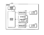
- FIG. 3 is a block diagram illustrating a configuration example of the portable device 2 according to the first embodiment.
- the portable device 2 includes a portable control unit 21 that controls the operation of each component of the portable device 2.
- the portable control unit 21 is a microcomputer having, for example, one or a plurality of CPUs, a multi-core CPU, a ROM, a RAM, a timer unit 21a, and the like.
- the mobile side control unit 21 is provided with a mobile side reception unit 22, a mobile side transmission unit 23, a mobile side storage unit 24, and a walking detection unit 25.
- the portable side control unit 21 reads out a control program described later stored in the portable side storage unit 24, controls the operation of each component unit, controls the operation of each component unit, and locks the vehicle door. The process which transmits the information required for a negative determination to the vehicle equipment 1 is performed.
- the portable storage unit 24 is a non-volatile memory similar to the in-vehicle storage unit 14.
- the portable-side storage unit 24 transmits a response signal including information necessary for determining whether or not the vehicle door needs to be locked to the in-vehicle device 1 by the portable-side control unit 21 controlling the operation of each component of the portable device 2.
- a control program for executing the processing to be performed is stored.
- the mobile-side receiver 22 is connected to the LF receiving antenna 22a, receives various signals such as an activation signal and a position detection signal transmitted from the vehicle-mounted device 1 using radio waves in the LF band, and the mobile-side controller 21. Output to.
- the LF receiving antenna 22a is, for example, a triaxial antenna, and a constant received signal strength can be obtained regardless of the orientation or posture of the portable device 2 with respect to the vehicle C.
- the mobile-side receiving unit 22 demodulates the position detection signal received by the LF receiving antenna 22 a and outputs the demodulated signal to the mobile-side control unit 21.
- the walking detection unit 25 includes a vibration sensor 25a that detects vertical vibration caused by walking of the user A holding the portable device 2, for example.
- the vibration sensor 25 a is, for example, an acceleration sensor, and is a circuit that outputs a signal indicating the detected vibration to the portable-side control unit 21.
- the portable side transmission unit 23 is connected to the RF transmission antenna 23 a and transmits various signals according to the control of the portable side control unit 21. For example, when the position detection signal transmitted from the in-vehicle device 1 is successfully received or demodulated, the portable side transmission unit 23 transmits a response signal. Moreover, the walking state signal detected by the walking detection unit 25, specifically, a walking state signal indicating a vibration state is transmitted. The mobile-side transmitting unit 23 continuously transmits the walking state signal for a predetermined time after receiving the position detection signal after activation. The portable-side transmitting unit 23 transmits a response signal using UHF band radio waves.
- the UHF band is an example of a radio wave band for transmitting signals, and is not necessarily limited to this.
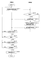
- FIG. 4 is a flowchart showing a locking processing procedure according to the first embodiment.
- the in-vehicle control unit 11 monitors the state of the open / close detection switch 7 and starts the following process, for example, triggered by the closing of the open vehicle door.
- the in-vehicle control unit 11 that has detected the opening / closing of the vehicle door causes the in-vehicle transmission unit 13 to transmit an activation signal for activating the portable device 2 and a position detection signal from the LF transmission antenna 3 (step S11).
- the portable device 2 is normally in a standby state with low power consumption, and transitions to the activated state when receiving the activation signal transmitted from the in-vehicle device 1.
- the activated portable device 2 has been activated for at least a predetermined time, and repeats the processing of steps S12 to S15 described later. Although details are omitted, the in-vehicle device 1 and the portable device 2 execute an authentication process when the portable device 2 is activated.
- the portable device 2 activated by the activation signal determines whether the position detection signal transmitted from the in-vehicle device 1 has been received by the portable-side receiving unit 22 (step S12).
- the in-vehicle device 1 determines that the position detection signal has been successfully received when the modulated position detection signal is successfully demodulated.
- the portable side control part 21 transmits a response signal to the vehicle equipment 1 (step S13).
- the portable control unit 21 uses the walking detection unit 25 to determine the walking state of the user A. That is, its own vibration state is detected (step S14).
- the portable side control part 21 transmits the walking state signal which shows the walking state of the user A detected by the walking detection part 25 in the portable side transmission part 23 (step S15).
- the process of steps S12 to S15 is repeatedly executed regardless of whether or not the position detection signal is received, and at least the walking state signal is intermittently transmitted to the in-vehicle device 1. is doing.
- the in-vehicle control unit 11 that has transmitted the position detection signal in step S11 determines whether the in-vehicle transmission unit 13 has received a response signal transmitted from the portable device 2 in accordance with the position detection signal (step S16). ). When it determines with having received the response signal (step S16: YES), the vehicle-mounted control part 11 returns a process to step S11.
- step S16 determines whether the portable device 2 is vibrating with reference to the information of the walking state which a walking state signal shows. (Step S17). That is, the vehicle-mounted control unit 11 determines whether or not the portable device 2 is vibrating up and down by the user A walking. When it determines with the portable device 2 not vibrating (step S17: NO), the vehicle-mounted control part 11 returns a process to step S11.
- step S17 When it determines with the portable device 2 vibrating (step S17: YES), the vehicle-mounted control part 11 has not received the response signal, and the state which the portable device 2 is vibrating continues. Is determined (step S18). For example, the in-vehicle control unit 11 does not receive a response signal in step S16 and step S17, and if the portable device 2 vibrates, the above state continues when it is continuously determined a predetermined number of times or more. It is determined that Further, as a modification, the in-vehicle control unit 11 measures the elapsed time from the time when it is first determined that the vehicle is in the above state by the timer unit 11a. It may be determined that the state continues.
- the vehicle-mounted control unit 11 that executes steps S16 to S17 functions as a determination unit that determines whether or not locking is necessary based on the walking state of the user A indicated by the walking state signal and the reception state of the response signal.
- step S18: NO If it is determined that the above state does not continue (step S18: NO), the vehicle-mounted control unit 11 returns the process to step S11.
- step S18: YES the vehicle-mounted control part 11 outputs a locking signal to the door ECU 6 in the output part 15 (step S19), and complete
- FIG. 5 is a conceptual diagram showing a communication range of the position detection signal, a response signal, and a walking state signal
- FIG. 6 is a communication range of the position detection signal and a walking state when the user A moves away from the vehicle C. It is a conceptual diagram which shows a signal.
- the semicircle indicated by a two-dot chain line indicates a position detection signal transmitted from the first to third LF transmission antennas 31, 32, and 33, and the magnitude thereof is the portable device 2. Indicates a range in which the position detection signal can be received.
- the portable device 2 can receive a position detection signal and transmits a response signal and a walking state signal to the in-vehicle device 1.
- a solid line arrow indicates a response signal
- a broken line arrow indicates a walking state signal.
- the portable device 2 when the portable device 2 leaves the vehicle C and goes out of the range in which the position detection signal can be received, the portable device 2 does not transmit a response signal, and only the walking state signal is sent to the in-vehicle device 1. To send. Even if the user A comes out of a range in which the position detection signal can be received, the user A is only stopped near the vehicle C, for example, after the vehicle C is inclined, and may not be separated from the vehicle C. . Therefore, the vehicle-mounted device 1 monitors the walking state of the pedestrian using the walking state signal in addition to the presence / absence of reception of the response signal, and does not receive the response signal as shown in FIG. When the continuous vibration of the portable device 2 due to the walking of A is detected, the vehicle door is locked. The in-vehicle device 1 does not lock the vehicle door when the portable device 2 is not vibrating even if the response signal is not received. If the response signal is not received and the portable device 2 vibrates temporarily, the vehicle door is not locked.
- the vehicle communication system configured as described above, it is possible to determine the situation where the portable device 2 moves away from the vehicle C without error and to lock the vehicle door.
- the situation where the portable device 2 moves away from the vehicle C is determined without error by taking into account the vibration of the portable device 2 due to the walking of the user A, and the vehicle door is locked. can do.
- the vehicle-mounted device 1 can determine the situation where the user A moves away from the vehicle C with higher accuracy and can lock the vehicle door.
- the vehicle communication system according to the second embodiment has the same configuration as that of the first embodiment, and the configuration of the walking detection unit 225 and the processing procedures of the in-vehicle device 1 and the portable device 202 are different. Since other configurations and operational effects are the same as those of the first embodiment, the differences will be mainly described below, and corresponding portions are denoted by the same reference numerals and detailed description thereof will be omitted.
- FIG. 7 is a block diagram illustrating a configuration example of the portable device 202 according to the second embodiment.
- a portable device 202 according to the second embodiment has the same configuration as that of the first embodiment.
- the walking detection unit 225 according to the second embodiment includes a multi-axis acceleration sensor 225a, specifically a 3-axis acceleration sensor, and vertical vibrations caused by walking of the user A holding the portable device 202 and linear acceleration in the traveling direction. And outputs a signal indicating the detected vertical vibration and linear acceleration to the portable control unit 21.
- FIG. 8 is a flowchart showing a locking processing procedure according to the second embodiment.
- the in-vehicle device 1 and the portable device 202 execute the same processing as Step S11 to Step S17 in Embodiment 1 in Step S211 to Step S217.
- the walking state detected by the portable control unit 21 in step S214 is vertical vibration and linear acceleration due to the walking of the user A
- the walking state signal transmitted in step S215 is the vibration and linear acceleration. Is shown.
- the vehicle-mounted control part 11 When it determines with the portable device 202 vibrating in step S217 (step S217: YES), the vehicle-mounted control part 11 further refers to the information of the walking state which a walking state signal shows, and the acceleration of the portable device 202 is linear. It is determined whether or not the target is correct (step S218).
- “acceleration is linear” means, for example, a state where the direction of acceleration increases or decreases toward a certain direction. It is assumed that the acceleration is also linear when the pedestrian moves at a constant speed and the acceleration becomes zero after the acceleration increases or decreases in a certain direction.
- step S218 If it is determined that the acceleration of the portable device 202 is not linear (step S218: NO), the in-vehicle control unit 11 returns the process to step S211. When it determines with the acceleration of the portable device 202 being linear (step S218: YES), the vehicle-mounted control part 11 has not received the response signal, and the portable device 202 vibrates and the acceleration is linear. It is determined whether or not the state continues (step S219).
- step S219: NO the vehicle-mounted control part 11 returns a process to step S211.
- step S219: YES the vehicle-mounted control part 11 outputs a locking signal to the door ECU 6 in the output part 15 (step S220), and complete
- the vehicle door is locked by the output of the locking signal.
- the vehicle-mounted control unit 11 that executes Steps S216 to S219 functions as a determination unit that determines whether or not locking is necessary based on the walking state of the user A indicated by the walking state signal and the reception state of the response signal.
- the vehicle communication system configured as described above, in addition to the reception state of the response signal, the situation where the portable device 202 moves away from the vehicle C in consideration of the vibration and acceleration of the portable device 202 caused by the walking of the user A is erroneous. It can be determined that the vehicle door is locked.
- the portable devices 2 and 202 are described as dedicated devices. However, a communication device such as a wearable terminal or a smartphone having the same communication function may be used as the portable devices 2 and 202.
Landscapes
- Engineering & Computer Science (AREA)
- Mechanical Engineering (AREA)
- Lock And Its Accessories (AREA)
Abstract
車両用通信システムは、位置検出用信号を送信する車載機(1)と、位置検出用信号を受信し、応じた応答信号を送信する携帯機(2)とを備える。携帯機(2)は、自身を保持する使用者の歩行状態を検出し、当該歩行状態を示す歩行状態信号を送信する。車載機(1)は、携帯機(2)から送信された応答信号及び歩行状態信号を受信し、受信した各信号に基づいて、車両ドアの施錠の要否を判定し、施錠要と判定された場合、車載機(1)は、施錠信号を出力する。
Description
本発明は、車両用通信システム、車載機及び携帯機に関する。
本出願は、2016年1月27日出願の日本出願第2016-13702号に基づく優先権を主張し、前記日本出願に記載された全ての記載内容を援用するものである。
本出願は、2016年1月27日出願の日本出願第2016-13702号に基づく優先権を主張し、前記日本出願に記載された全ての記載内容を援用するものである。
メカニカルキーを用いずに車両ドアの施錠及び解錠を行う車両用通信システムが実用化されている。具体的には、携帯機を所持した使用者が車両に近づき、又はドアハンドルを握るだけで車両ドアの解錠を行うスマートエントリー(登録商標)システム等が実用化されている。
また、メカニカルキーを用いずに車両のエンジン始動を行う車両用通信システムも実用化されている。具体的には、携帯機を所持した使用者がエンジンスタートスイッチを押すだけでエンジンの始動を行うスマートスタート(登録商標)システムが実用化されている。
更に、車載機から定期的に送信される位置検出用信号に対する携帯機からの応答信号が無くなった場合に車両ドアを自動的に施錠するウォークアウェイクロージング(WAC: Walk Away Closing)システムがある。また、車載機から送信されるLF帯の位置検出用信号の受信信号強度を携帯機が測定し、当該受信信号強度が減少した場合、使用者が車両から遠ざかったものと判定し、車両ドアを自動的に施錠するWACシステムがある。
また、メカニカルキーを用いずに車両のエンジン始動を行う車両用通信システムも実用化されている。具体的には、携帯機を所持した使用者がエンジンスタートスイッチを押すだけでエンジンの始動を行うスマートスタート(登録商標)システムが実用化されている。
更に、車載機から定期的に送信される位置検出用信号に対する携帯機からの応答信号が無くなった場合に車両ドアを自動的に施錠するウォークアウェイクロージング(WAC: Walk Away Closing)システムがある。また、車載機から送信されるLF帯の位置検出用信号の受信信号強度を携帯機が測定し、当該受信信号強度が減少した場合、使用者が車両から遠ざかったものと判定し、車両ドアを自動的に施錠するWACシステムがある。
本態様に係る車両用通信システムは、位置検出用信号を送信する車載機と、前記位置検出用信号を受信し、応答信号を送信する携帯機とを備え、前記車載機は該携帯機から送信される前記応答信号の受信状態に応じて、車両ドアの施錠を指示する施錠信号を出力する車両用通信システムであって、前記携帯機は、該携帯機を保持する使用者の歩行状態を検出する歩行検出部と、該歩行検出部によって検出された前記使用者の歩行状態を示す歩行状態信号を送信する送信部とを備え、前記車載機は、前記携帯機から送信された前記応答信号及び前記歩行状態信号を受信する受信部と、該受信部にて受信した前記歩行状態信号が示す前記使用者の歩行状態及び前記応答信号の受信状態に基づいて、施錠の要否を判定する判定部と、該判定部にて施錠要と判定された場合、前記施錠信号を出力する出力部とを備える。
本態様に係る車載機は、位置検出用信号を送信し、該位置検出用信号を受信した携帯機から送信される応答信号の受信状態に応じて、車両ドアの施錠を指示する車載機であって、前記携帯機から送信された前記応答信号及び前記携帯機を保持する使用者の歩行状態を示す歩行状態信号を受信する受信部と、該受信部にて受信した前記歩行状態信号が示す前記使用者の歩行状態及び前記応答信号の受信状態に基づいて、施錠の要否を判定する判定部と、該判定部にて施錠要と判定された場合、車両ドアの施錠を指示する施錠信号を出力する出力部とを備える。
本態様に係る携帯機は、車載機から送信された位置検出用信号を受信し、応答信号を送信する携帯機であって、自身を保持する使用者の歩行状態を検出する歩行検出部と、該歩行検出部によって検出された前記使用者の歩行状態を示す歩行状態信号を送信する送信部とを備える。
なお、本願は、このような特徴的な処理部を備える車両用通信システム、車載機及び携帯機として実現することができるだけでなく、かかる特徴的な処理をステップとする車両通信方法として実現したり、かかるステップをコンピュータに実行させるためのプログラムとして実現したりすることができる。また、車両用通信システム、車載機及び携帯機の一部又は全部を実現する半導体集積回路として実現したり、車両用通信システム、車載機及び携帯機を含むその他のシステムとして実現したりすることができる。
[本開示が解決しようとする課題]
LF帯の位置検出用信号を携帯機が受信できる範囲は、位置検出用信号を送信するアンテナを中心にして半径約2~3m程度であり、携帯機を保持した使用者が車両から遠ざかったことを精度良く判定することができないという問題がある。
例えば、位置検出用信号を送信するアンテナが、運転席側の車両ドア付近、助手席側の車両ドア付近、バックドア付近に設けられている場合、使用者が運転席からバックドア付近へ移動する途中で携帯機が位置検出用信号の受信に失敗し、車両ドアが施錠されてしまうことがある。また、バックドアを開くために、使用者が車両後方に離れた際、携帯機が位置検出用信号の受信に失敗し、車両ドアが施錠されてしまうことがある。
例えば、位置検出用信号を送信するアンテナが、運転席側の車両ドア付近、助手席側の車両ドア付近、バックドア付近に設けられている場合、使用者が運転席からバックドア付近へ移動する途中で携帯機が位置検出用信号の受信に失敗し、車両ドアが施錠されてしまうことがある。また、バックドアを開くために、使用者が車両後方に離れた際、携帯機が位置検出用信号の受信に失敗し、車両ドアが施錠されてしまうことがある。
本願の目的は、携帯機が車両から遠ざかる状況を誤り無く判定し、車両ドアを施錠することができる車両用通信システム、車載機及び携帯機を提供することにある。
[本開示の効果]
本開示によれば、携帯機が車両から遠ざかる状況を誤り無く判定し、車両ドアを施錠することができる車両用通信システム、車載機及び携帯機を提供することができる。
本開示によれば、携帯機が車両から遠ざかる状況を誤り無く判定し、車両ドアを施錠することができる車両用通信システム、車載機及び携帯機を提供することができる。
[本発明の実施形態の説明]
最初に本発明の実施態様を列記して説明する。また、以下に記載する実施形態の少なくとも一部を任意に組み合わせてもよい。
最初に本発明の実施態様を列記して説明する。また、以下に記載する実施形態の少なくとも一部を任意に組み合わせてもよい。
(1)本態様に係る車両用通信システムは、位置検出用信号を送信する車載機と、前記位置検出用信号を受信し、応答信号を送信する携帯機とを備え、前記車載機は該携帯機から送信される前記応答信号の受信状態に応じて、車両ドアの施錠を指示する施錠信号を出力する車両用通信システムであって、前記携帯機は、該携帯機を保持する使用者の歩行状態を検出する歩行検出部と、該歩行検出部によって検出された前記使用者の歩行状態を示す歩行状態信号を送信する送信部とを備え、前記車載機は、前記携帯機から送信された前記応答信号及び前記歩行状態信号を受信する受信部と、該受信部にて受信した前記歩行状態信号が示す前記使用者の歩行状態及び前記応答信号の受信状態に基づいて、施錠の要否を判定する判定部と、該判定部にて施錠要と判定された場合、前記施錠信号を出力する出力部とを備える。
本態様によれば、携帯機は、車載機から送信される位置検出用信号を受信した場合、応答信号を送信する。また、携帯機は、自身を保持する使用者の歩行状態を示す歩行状態信号を送信する。
車載機は携帯機から送信される応答信号及び歩行状態信号を受信する。車載機は、応答信号の受信状態に加え、歩行状態信号が示す使用者の歩行状態に基づいて、使用者が車両から遠ざかり、車両ドアの施錠を要するか否かを判定することができる。出力部は、施錠要と判定された場合、施錠信号を出力し、車両ドアを施錠させる。
以上の通り、本態様によれば、携帯機による位置検出用信号の受信状態のみならず、使用者の歩行状態を加味して、使用者が車両から遠ざかる状況にあることを判定することができる。従って、使用者が保持する携帯機が車両から遠ざかる状況を、より精度良く判定し、車両ドアを施錠することができる。
車載機は携帯機から送信される応答信号及び歩行状態信号を受信する。車載機は、応答信号の受信状態に加え、歩行状態信号が示す使用者の歩行状態に基づいて、使用者が車両から遠ざかり、車両ドアの施錠を要するか否かを判定することができる。出力部は、施錠要と判定された場合、施錠信号を出力し、車両ドアを施錠させる。
以上の通り、本態様によれば、携帯機による位置検出用信号の受信状態のみならず、使用者の歩行状態を加味して、使用者が車両から遠ざかる状況にあることを判定することができる。従って、使用者が保持する携帯機が車両から遠ざかる状況を、より精度良く判定し、車両ドアを施錠することができる。
(2)前記歩行検出部は、前記使用者の歩行による振動を検出する振動センサを備え、前記判定部は、前記振動センサが前記使用者の歩行による継続的な振動を検出しており、かつ前記位置検出用信号を受信した前記携帯機から送信される前記応答信号を受信していない場合、施錠要と判定する構成が好ましい。
本態様によれば、車載機は、応答信号の受信状態と、使用者の歩行による継続的な振動とに基づいて、使用者が車両から遠ざかる状況にあることを判定することができる。
従って、例えば、携帯機が位置検出用信号を受信できない車両周辺の特定の位置に使用者が移動した場合であっても、使用者が静止しているような状況であれば、使用者が車両から遠ざかった状況にあると誤判定されることは無く、車両ドアが施錠されてしまうことも無い。
従って、例えば、携帯機が位置検出用信号を受信できない車両周辺の特定の位置に使用者が移動した場合であっても、使用者が静止しているような状況であれば、使用者が車両から遠ざかった状況にあると誤判定されることは無く、車両ドアが施錠されてしまうことも無い。
(3)前記歩行検出部は、前記使用者の歩行による振動及び直線加速度を検出する多軸加速度センサを備え、前記判定部は、前記多軸加速度センサが前記使用者の歩行による継続的な振動及び直線加速度を検出し、かつ前記位置検出用信号を受信した前記携帯機から送信される前記応答信号を受信していない場合、施錠要と判定する構成が好ましい。
本態様によれば、車載機は、応答信号の受信状態と、使用者の歩行による継続的な振動及び直線加速度とに基づいて、使用者が車両から遠ざかる状況にあることを判定することができる。
従って、例えば、携帯機が位置検出用信号を受信できない車両周辺の特定の位置に使用者が移動した場合であっても、使用者が車両の周囲を周回している等、非直線的に歩行している状況であれば、使用者が車両から遠ざかった状況にあると誤判定されることは無く、車両ドアが施錠されてしまうことも無い。
従って、例えば、携帯機が位置検出用信号を受信できない車両周辺の特定の位置に使用者が移動した場合であっても、使用者が車両の周囲を周回している等、非直線的に歩行している状況であれば、使用者が車両から遠ざかった状況にあると誤判定されることは無く、車両ドアが施錠されてしまうことも無い。
(4)前記携帯機は、前記位置検出用信号を受信しなくなった後も前記歩行状態信号を間欠的に送信しており、前記出力部は、前記判定部が、前記携帯機から間欠的に送信される前記歩行状態信号に基づいて複数回施錠要と判定した場合、前記施錠信号を出力する構成が好ましい。
本態様によれば、車載機は、応答信号の受信状態及び使用者の歩行状態を継続的に監視しており、複数回、施錠要と判定された場合、施錠信号を出力し、車両ドアを施錠させる。
従って、使用者が保持する携帯機が車両から遠ざかる状況を、より精度良く判定し、車両ドアを施錠することができる。
従って、使用者が保持する携帯機が車両から遠ざかる状況を、より精度良く判定し、車両ドアを施錠することができる。
(5)本態様に係る車載機は、位置検出用信号を送信し、該位置検出用信号を受信した携帯機から送信される応答信号の受信状態に応じて、車両ドアの施錠を指示する車載機であって、前記携帯機から送信された前記応答信号及び前記携帯機を保持する使用者の歩行状態を示す歩行状態信号を受信する受信部と、該受信部にて受信した前記歩行状態信号が示す前記使用者の歩行状態及び前記応答信号の受信状態に基づいて、施錠の要否を判定する判定部と、該判定部にて施錠要と判定された場合、車両ドアの施錠を指示する施錠信号を出力する出力部とを備える。
本態様の車載機は、携帯機が車両から遠ざかる状況を誤り無く判定し、車両ドアを施錠することができる車両用通信システムを構成することができる。
(6)本態様に係る携帯機は、車載機から送信された位置検出用信号を受信し、応答信号を送信する携帯機であって、自身を保持する使用者の歩行状態を検出する歩行検出部と、該歩行検出部によって検出された前記使用者の歩行状態を示す歩行状態信号を送信する送信部とを備える。
本態様の携帯機は、携帯機が車両から遠ざかる状況を誤り無く判定し、車両ドアを施錠することができる車両用通信システムを構成することができる。
[本発明の実施形態の詳細]
本発明の実施形態に係る車両用通信システムの具体例を、以下に図面を参照しつつ説明する。なお、本発明はこれらの例示に限定されるものではなく、請求の範囲によって示され、請求の範囲と均等の意味及び範囲内でのすべての変更が含まれることが意図される。
本発明の実施形態に係る車両用通信システムの具体例を、以下に図面を参照しつつ説明する。なお、本発明はこれらの例示に限定されるものではなく、請求の範囲によって示され、請求の範囲と均等の意味及び範囲内でのすべての変更が含まれることが意図される。
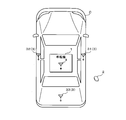
図1は、実施形態1に係る車両用通信システムの一構成例を示すブロック図である。本実施形態1に係る車両用通信システムは、車両Cに設けられた複数のLF送信アンテナ3及びRF受信アンテナ4を用いて各種信号を送受信する車載機1と、該車載機1との間で該信号を送受信する携帯機2とを備える。車載機1は、携帯機2の位置、当該携帯機2を保持する使用者A(図5及び図6参照)の歩行状態から、携帯機2が車両Cから遠ざかる状態を判定し、かかる状態にある場合、車両ドアを自動的に施錠する。
複数のLF送信アンテナ3は、例えば、運転席側のピラーに配された第1LF送信アンテナ31、助手席側のピラーに配された第2LF送信アンテナ32、バックドア側に配された第3LF送信アンテナ33等である。各LF送信アンテナ3はLF帯の電波を用いて信号を送信する。
複数のLF送信アンテナ3は、例えば、運転席側のピラーに配された第1LF送信アンテナ31、助手席側のピラーに配された第2LF送信アンテナ32、バックドア側に配された第3LF送信アンテナ33等である。各LF送信アンテナ3はLF帯の電波を用いて信号を送信する。
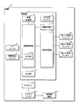
図2は、実施形態1に係る車載機1の一構成例を示すブロック図である。車載機1は、該車載機1の各構成部の動作を制御する車載制御部11を備える。車載制御部11は、例えば一又は複数のCPU(Central Processing Unit)、マルチコアCPU、ROM(Read Only Memory)、RAM(Random Access Memory)、計時部11a等を有するマイコンである。車載制御部11には、車載受信部12、車載送信部13、車載記憶部14及び出力部15が設けられている。
車載制御部11は、車載記憶部14に記憶されている後述の制御プログラムを実行することにより、各構成部の動作を制御し、携帯機2の位置を特定し、携帯機2が車両Cから遠ざかっている状況で車両ドアを自動的に施錠させる制御を行う。
車載記憶部14は、EEPROM(Electrically Erasable Programmable ROM)、フラッシュメモリ等の不揮発性メモリである。車載記憶部14は、車載制御部11が車載機1の各構成部の動作を制御することにより、携帯機2の位置を特定し、携帯機2を保持する使用者Aの歩行状態に応じて車両ドアを施錠させるための制御プログラムを記憶している。
車載受信部12はRF受信アンテナ4に接続されており、携帯機2からUHF帯の電波を用いて送信された各種信号を受信し、車載制御部11へ出力する。UHF帯の電波で通信可能な領域は広いため、車両CにおけるRF受信アンテナ4の配置は特に限定されない。
車載送信部13は複数のLF送信アンテナ3に接続されており、車載制御部11の制御に従って、携帯機2の位置を特定するための各種信号を送信する。例えば、車載送信部13は、車載制御部11の制御に従って、携帯機2を起動させる起動信号、携帯機2の位置を検出するための位置検出用信号を送信する。位置検出用信号は、携帯機2における当該位置検出用信号の受信の成否に基づいて、当該携帯機2の位置を特定するための信号である。位置検出用信号は例えば変調された搬送波である。第1LF送信アンテナ31から送信される位置検出用信号の強度は、運転席側の車両ドア近傍、例えば2~3mの範囲で携帯機2が位置検出用信号を受信できるような強度である。同様に、第2LF送信アンテナ32及び第3LF送信アンテナ33から送信される位置検出用信号の強度は、助手席側及びバックドア側の車両ドア近傍、例えば2~3mの範囲で携帯機2が位置検出用信号を受信できるような強度である。
出力部15にはドアECU6が接続されており、出力部15は、車載制御部11の制御に従って、車両ドアの施錠を指示する施錠信号をドアECU6へ出力する。車両Cには、車両ドアを施解錠させる公知の施解錠機構61と、施解錠機構61を駆動させるアクチュエータ62とが設けられている。ドアECU6には、アクチュエータ62が接続されており、車載機1の出力部15から出力された施錠信号に従って、アクチュエータ62を動作させ、車両ドアを施錠させる。
車載制御部11には、ドアスイッチ5が接続されており、該ドアスイッチ5の操作状態に対応したドア信号が車載制御部11に入力する。車載制御部11はドアスイッチ5のドア信号に基づいて、ドアスイッチ5の操作状態を認識することができる。車載制御部11は、車両ドアが解錠されている状態でドアスイッチ5が操作され、正規の携帯機2が車外にあることが確認された場合、施錠信号を出力部15にてドアECU6へ出力し、車両ドアを施錠させる。また、車載制御部11は、車両ドアが施錠されている状態でドアスイッチ5が操作され、正規の携帯機2が車外にあることが確認された場合、解錠信号を出力部15にてドアECU6へ出力し、車両ドアを解錠させる。
また、車載制御部11には、車両ドアの開閉状態を検出するための開閉検出スイッチ7が接続されている。開閉検出スイッチ7は、車両ドアの開閉に応じてオンオフする開閉信号が車載制御部11に入力する。車載制御部11は、入力した開閉信号に基づいて、車両ドアの開閉状態を認識することができる。
また、車載制御部11には、車両ドアの開閉状態を検出するための開閉検出スイッチ7が接続されている。開閉検出スイッチ7は、車両ドアの開閉に応じてオンオフする開閉信号が車載制御部11に入力する。車載制御部11は、入力した開閉信号に基づいて、車両ドアの開閉状態を認識することができる。
図3は、実施形態1に係る携帯機2の一構成例を示すブロック図である。携帯機2は、該携帯機2の各構成部の動作を制御する携帯側制御部21を備える。携帯側制御部21は、例えば一又は複数のCPU、マルチコアCPU、ROM、RAM、計時部21a等を有するマイコンである。携帯側制御部21には、携帯側受信部22、携帯側送信部23、携帯側記憶部24及び歩行検出部25が設けられている。
携帯側制御部21は、携帯側記憶部24に記憶されている後述の制御プログラムを読み出し、各構成部の動作を制御することにより、各構成部の動作を制御し、車両ドアの施錠の要否判定に必要な情報を車載機1へ送信する処理を実行する。
携帯側記憶部24は、車載記憶部14と同様の不揮発性メモリである。携帯側記憶部24は、携帯側制御部21が携帯機2の各構成部の動作を制御することにより、車両ドアの施錠要否判定に必要な情報を含む応答信号等を車載機1へ送信する処理を実行するための制御プログラムを記憶している。
携帯側受信部22はLF受信アンテナ22aに接続されており、車載機1からLF帯の電波を用いて送信された起動信号、位置検出用信号等の各種信号を受信し、携帯側制御部21へ出力する。LF受信アンテナ22aは例えば3軸アンテナであり、車両Cに対する携帯機2の向き又は姿勢に拘わらず、一定の受信信号強度が得られる。携帯側受信部22は、LF受信アンテナ22aにて受信された位置検出用信号を復調し、復調して得た信号を携帯側制御部21へ出力する。
歩行検出部25は、例えば携帯機2を保持する使用者Aの歩行による上下振動を検出する振動センサ25aを備える。振動センサ25aは、例えば加速度センサであり、検出した振動を示す信号を携帯側制御部21へ出力する回路である。
携帯側送信部23はRF送信アンテナ23aに接続されており、携帯側制御部21の制御に従って、各種信号を送信する。例えば、車載機1から送信された位置検出用信号の受信ないし復調に成功した場合、携帯側送信部23は、応答信号を送信する。また、歩行検出部25にて検出して得た歩行状態、具体的には振動状態を示す歩行状態信号を送信する。携帯側送信部23は、起動後、位置検出用信号を受信しなくなった後も、所定時間、継続して歩行状態信号を送信する。携帯側送信部23はUHF帯の電波を用いて応答信号を送信する。なおUHF帯は信号を送信する電波帯域の一例であり、必ずしもこれに限定されない。
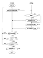
図4は、実施形態1に係る施錠処理手順を示すフローチャートである。車載制御部11は、開閉検出スイッチ7の状態を監視しており、例えば、開いた状態にある車両ドアが閉じたことをトリガとして、以下の処理を開始する。車両ドアの開閉を検出した車載制御部11は、携帯機2を起動させる起動信号及び位置検出用信号を、LF送信アンテナ3から車載送信部13に送信させる(ステップS11)。携帯機2は、通常、消費電力が小さい待機状態にあり、車載機1から送信された起動信号を受信した場合、起動状態に遷移する。起動した携帯機2は、少なくとも所定時間、起動しており、後述のステップS12~ステップS15の処理を繰り返し実行する。なお、詳細は省略するが、携帯機2の起動時に車載機1及び携帯機2は認証処理を実行している。
起動信号によって起動した携帯機2は、車載機1から送信された位置検出用信号を携帯側受信部22にて受信したか否かを判定する(ステップS12)。車載機1は、変調された位置検出用信号の復調に成功した場合、位置検出用信号を受信できたと判定する。位置検出用信号を受信できたと判定した場合(ステップS12:YES)、携帯側制御部21は、応答信号を車載機1へ送信する(ステップS13)。ステップS13の処理を終えた場合、又は位置検出用信号を受信できていないと判定した場合(ステップS12:NO)、携帯側制御部21は、歩行検出部25にて、使用者Aの歩行状態、即ち自身の振動状態を検出する(ステップS14)。そして、携帯側制御部21は、歩行検出部25にて検出された使用者Aの歩行状態を示す歩行状態信号を、携帯側送信部23にて送信する(ステップS15)。
携帯機2は、起動状態にある場合、位置検出用信号の受信の有無に拘わらず、ステップS12~ステップS15の処理を繰り返し実行しており、少なくとも歩行状態信号を車載機1へ間欠的に送信している。
携帯機2は、起動状態にある場合、位置検出用信号の受信の有無に拘わらず、ステップS12~ステップS15の処理を繰り返し実行しており、少なくとも歩行状態信号を車載機1へ間欠的に送信している。
ステップS11で位置検出用信号を送信した車載制御部11は、位置検出用信号に応じて携帯機2から送信される応答信号を車載送信部13にて受信したか否かを判定する(ステップS16)。応答信号を受信したと判定した場合(ステップS16:YES)、車載制御部11は、処理をステップS11へ戻す。
応答信号を受信していないと判定した場合(ステップS16:NO)、車載制御部11は、歩行状態信号が示す歩行状態の情報を参照し、携帯機2が振動しているか否かを判定する(ステップS17)。つまり、車載制御部11は、使用者Aの歩行によって、携帯機2が上下に振動しているか否かを判定する。携帯機2が振動していないと判定した場合(ステップS17:NO)、車載制御部11は処理をステップS11へ戻す。
携帯機2が振動していると判定した場合(ステップS17:YES)、車載制御部11は、応答信号を受信しておらず、かつ携帯機2が振動している状態が継続しているか否かを判定する(ステップS18)。例えば、車載制御部11は、ステップS16及びステップS17において、応答信号を受信しておらず、携帯機2が振動していると、所定回数以上、連続的に判定された場合、上記状態が継続していると判定する。また、変形例として、車載制御部11は、上記状態にあると最初に判定された時からの経過時間を計時部11aにて計時し、所定時間が経過しても上記状態にある場合、上記状態が継続していると判定しても良い。
なお、ステップS16~ステップS17を実行する車載制御部11は、歩行状態信号が示す使用者Aの歩行状態及び応答信号の受信状態に基づいて、施錠の要否を判定する判定部として機能する。
なお、ステップS16~ステップS17を実行する車載制御部11は、歩行状態信号が示す使用者Aの歩行状態及び応答信号の受信状態に基づいて、施錠の要否を判定する判定部として機能する。
上記状態が継続していないと判定した場合(ステップS18:NO)、車載制御部11は、処理をステップS11へ戻す。上記状態が継続していると判定した場合(ステップS18:YES)、車載制御部11は、出力部15にて施錠信号をドアECU6へ出力し(ステップS19)、処理を終える。施錠信号の出力によって、車両ドアは施錠される。
以上の処理を実行する車載機1及び携帯機2の動作を具体的に説明する。
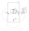
図5は、位置検出用信号の通信範囲、応答信号及び歩行状態信号を示す概念図、図6は、使用者Aが車両Cから離れていく状況での位置検出用信号の通信範囲及び歩行状態信号を示す概念図である。車両Cから出た使用者Aが車両ドアを閉じると、車載機1の第1乃至第3LF送信アンテナ31、32、33から位置検出用信号が送信させる。図5及び図6中、二点鎖線で示された半円は、第1乃至第3LF送信アンテナ31、32、33から送信させる位置検出用信号を示しており、その大きさは、携帯機2が当該位置検出用信号を受信できる範囲を示している。
図5は、位置検出用信号の通信範囲、応答信号及び歩行状態信号を示す概念図、図6は、使用者Aが車両Cから離れていく状況での位置検出用信号の通信範囲及び歩行状態信号を示す概念図である。車両Cから出た使用者Aが車両ドアを閉じると、車載機1の第1乃至第3LF送信アンテナ31、32、33から位置検出用信号が送信させる。図5及び図6中、二点鎖線で示された半円は、第1乃至第3LF送信アンテナ31、32、33から送信させる位置検出用信号を示しており、その大きさは、携帯機2が当該位置検出用信号を受信できる範囲を示している。
使用者Aが車両C近傍に位置している場合、携帯機2は、位置検出用信号を受信することができ、応答信号及び歩行状態信号を車載機1へ送信する。図5中、実線矢印は応答信号を示し、破線矢印は歩行状態信号を示している。
図6に示すように、携帯機2が車両Cから離れ、位置検出用信号を受信可能な範囲を出た場合、携帯機2は応答信号を送信せず、歩行状態信号のみを車載機1へ送信するようになる。位置検出用信号を受信可能な範囲から使用者Aが出ても、使用者Aは、車両Cの近く、例えば車両Cの斜め後に立ち止まっているだけであり、車両Cから離れていない場合もある。そこで、車載機1は、応答信号の受信の有無に加え、歩行状態信号を用いて、歩行者の歩行状態を監視し、図6に示すように、応答信号を受信しておらず、使用者Aの歩行による携帯機2の継続的な振動を検出した場合に、車両ドアを施錠する。車載機1は、応答信号を受信していなくても、携帯機2が振動していない場合、車両ドアを施錠しない。また、応答信号を受信しておらず、携帯機2が振動する状態が一時的なものである場合、車両ドアを施錠しない。
このように構成された車両用通信システムによれば、携帯機2が車両Cから遠ざかる状況を誤り無く判定し、車両ドアを施錠することができる。
特に、本実施形態1では、応答信号の受信状態に加え、使用者Aの歩行による携帯機2の振動を加味して携帯機2が車両Cから遠ざかる状況を誤り無く判定し、車両ドアを施錠することができる。
更に、車載機1は、使用者Aが車両Cから遠ざかる状況を、より精度良く判定し、車両ドアを施錠することができる。
(実施形態2)
本実施形態2に係る車両用通信システムは、実施形態1と同様の構成であり、歩行検出部225の構成及び車載機1及び携帯機202の処理手順が異なる。その他の構成及び作用効果は実施形態1と同様であるため、以下では、主にかかる相違点を説明し、対応する箇所には同様の符号を付して詳細な説明を省略する。
本実施形態2に係る車両用通信システムは、実施形態1と同様の構成であり、歩行検出部225の構成及び車載機1及び携帯機202の処理手順が異なる。その他の構成及び作用効果は実施形態1と同様であるため、以下では、主にかかる相違点を説明し、対応する箇所には同様の符号を付して詳細な説明を省略する。
図7は、実施形態2に係る携帯機202の一構成例を示すブロック図である。実施形態2に係る携帯機202は、実施形態1と同様の構成を備える。実施形態2に係る歩行検出部225は、多軸加速度センサ225a、具体的には3軸加速度センサを備え、携帯機202を保持する使用者Aの歩行による上下の振動と、進行方向における直線加速度とを検出し、検出した上下振動及び直線加速度を示す信号を携帯側制御部21へ出力する。
図8は、実施形態2に係る施錠処理手順を示すフローチャートである。車載機1及び携帯機202は、実施形態1におけるステップS11~ステップS17と同様の処理をステップS211~ステップS217にて実行する。但し、ステップS214にて携帯側制御部21が検出する歩行状態は、使用者Aの歩行による上下の振動及び直線加速度であり、ステップS215にて送信される歩行状態信号は、当該振動及び直線加速度を示すものである。
ステップS217にて携帯機202が振動していると判定した場合(ステップS217:YES)、更に車載制御部11は、歩行状態信号が示す歩行状態の情報を参照し、携帯機202の加速度が直線的であるか否かを判定する(ステップS218)。ここで加速度が直線的とは、例えば、加速度の方向がある一定の方向を向いて増減している状態を言う。加速度が一定の方向で増減した後、歩行者の移動が等速になって加速度が0になった場合も加速度が直線的であるものとする。
携帯機202の加速度が直線的で無いと判定された場合(ステップS218:NO)、車載制御部11は、処理をステップS211へ戻す。携帯機202の加速度が直線的であると判定した場合(ステップS218:YES)、車載制御部11は、応答信号を受信しておらず、かつ携帯機202が振動し、加速度が直線的である状態が継続しているか否かを判定する(ステップS219)。
上記状態が継続していないと判定した場合(ステップS219:NO)、車載制御部11は、処理をステップS211へ戻す。上記状態が継続していると判定した場合(ステップS219:YES)、車載制御部11は、出力部15にて施錠信号をドアECU6へ出力し(ステップS220)、処理を終える。施錠信号の出力によって、車両ドアは施錠される。
なお、ステップS216~ステップS219を実行する車載制御部11は、歩行状態信号が示す使用者Aの歩行状態及び応答信号の受信状態に基づいて、施錠の要否を判定する判定部として機能する。
なお、ステップS216~ステップS219を実行する車載制御部11は、歩行状態信号が示す使用者Aの歩行状態及び応答信号の受信状態に基づいて、施錠の要否を判定する判定部として機能する。
このように構成された車両用通信システムによれば、応答信号の受信状態に加え、使用者Aの歩行による携帯機202の振動及び加速度を加味して携帯機202が車両Cから遠ざかる状況を誤り無く判定し、車両ドアを施錠することができる。
なお、実施形態1及び2では、携帯機2、202を専用機として説明したが、同様の通信機能を有するウェアラブル端末、スマートフォン等の通信機を携帯機2、202として利用しても良い。
今回開示された実施形態はすべての点で例示であって、制限的なものではないと考えられるべきである。本発明の範囲は、上記した意味ではなく、請求の範囲によって示され、請求の範囲と均等の意味及び範囲内でのすべての変更が含まれることが意図される。
1 車載機
2,202 携帯機
3 LF送信アンテナ
4 RF受信アンテナ
5 ドアスイッチ
6 ドアECU
7 開閉検出スイッチ
11 車載制御部
11a 計時部
12 車載受信部
13 車載送信部
14 車載記憶部
15 出力部
21 携帯側制御部
21a 計時部
22 携帯側受信部
22a LF受信アンテナ
23 携帯側送信部
23a RF送信アンテナ
24 携帯側記憶部
25,225 歩行検出部
25a 振動センサ
31 第1LF送信アンテナ
32 第2LF送信アンテナ
33 第3LF送信アンテナ
61 施解錠機構
62 アクチュエータ
225a 多軸加速度センサ
A 使用者
C 車両
2,202 携帯機
3 LF送信アンテナ
4 RF受信アンテナ
5 ドアスイッチ
6 ドアECU
7 開閉検出スイッチ
11 車載制御部
11a 計時部
12 車載受信部
13 車載送信部
14 車載記憶部
15 出力部
21 携帯側制御部
21a 計時部
22 携帯側受信部
22a LF受信アンテナ
23 携帯側送信部
23a RF送信アンテナ
24 携帯側記憶部
25,225 歩行検出部
25a 振動センサ
31 第1LF送信アンテナ
32 第2LF送信アンテナ
33 第3LF送信アンテナ
61 施解錠機構
62 アクチュエータ
225a 多軸加速度センサ
A 使用者
C 車両
Claims (6)
- 位置検出用信号を送信する車載機と、前記位置検出用信号を受信し、応答信号を送信する携帯機とを備え、前記車載機は該携帯機から送信される前記応答信号の受信状態に応じて、車両ドアの施錠を指示する施錠信号を出力する車両用通信システムであって、
前記携帯機は、
該携帯機を保持する使用者の歩行状態を検出する歩行検出部と、
該歩行検出部によって検出された前記使用者の歩行状態を示す歩行状態信号を送信する送信部と
を備え、
前記車載機は、
前記携帯機から送信された前記応答信号及び前記歩行状態信号を受信する受信部と、
該受信部にて受信した前記歩行状態信号が示す前記使用者の歩行状態及び前記応答信号の受信状態に基づいて、施錠の要否を判定する判定部と、
該判定部にて施錠要と判定された場合、前記施錠信号を出力する出力部と
を備える車両用通信システム。 - 前記歩行検出部は、
前記使用者の歩行による振動を検出する振動センサを備え、
前記判定部は、
前記振動センサが前記使用者の歩行による継続的な振動を検出しており、かつ前記位置検出用信号を受信した前記携帯機から送信される前記応答信号を受信していない場合、施錠要と判定する
請求項1に記載の車両用通信システム。 - 前記歩行検出部は、
前記使用者の歩行による振動及び直線加速度を検出する多軸加速度センサを備え、
前記判定部は、
前記多軸加速度センサが前記使用者の歩行による継続的な振動及び直線加速度を検出し、かつ前記位置検出用信号を受信した前記携帯機から送信される前記応答信号を受信していない場合、施錠要と判定する
請求項1に記載の車両用通信システム。 - 前記携帯機は、
前記位置検出用信号を受信しなくなった後も前記歩行状態信号を間欠的に送信しており、
前記出力部は、
前記判定部が、前記携帯機から間欠的に送信される前記歩行状態信号に基づいて複数回施錠要と判定した場合、前記施錠信号を出力する
請求項1~請求項3までのいずれか一項に記載の車両用通信システム。 - 位置検出用信号を送信し、該位置検出用信号を受信した携帯機から送信される応答信号の受信状態に応じて、車両ドアの施錠を指示する車載機であって、
前記携帯機から送信された前記応答信号及び前記携帯機を保持する使用者の歩行状態を示す歩行状態信号を受信する受信部と、
該受信部にて受信した前記歩行状態信号が示す前記使用者の歩行状態及び前記応答信号の受信状態に基づいて、施錠の要否を判定する判定部と、
該判定部にて施錠要と判定された場合、車両ドアの施錠を指示する施錠信号を出力する出力部と
を備える車載機。 - 車載機から送信された位置検出用信号を受信し、応答信号を送信する携帯機であって、
自身を保持する使用者の歩行状態を検出する歩行検出部と、
該歩行検出部によって検出された前記使用者の歩行状態を示す歩行状態信号を送信する送信部と
を備える携帯機。
Priority Applications (2)
| Application Number | Priority Date | Filing Date | Title |
|---|---|---|---|
| US16/069,565 US20190054897A1 (en) | 2016-01-27 | 2017-01-16 | Vehicle communication system, on-board device, and portable device |
| CN201780006236.8A CN109072633A (zh) | 2016-01-27 | 2017-01-16 | 车辆用通信系统、车载设备及便携设备 |
Applications Claiming Priority (2)
| Application Number | Priority Date | Filing Date | Title |
|---|---|---|---|
| JP2016013702A JP6520735B2 (ja) | 2016-01-27 | 2016-01-27 | 車両用通信システム、車載機及び携帯機 |
| JP2016-013702 | 2016-01-27 |
Publications (1)
| Publication Number | Publication Date |
|---|---|
| WO2017130772A1 true WO2017130772A1 (ja) | 2017-08-03 |
Family
ID=59398034
Family Applications (1)
| Application Number | Title | Priority Date | Filing Date |
|---|---|---|---|
| PCT/JP2017/001240 Ceased WO2017130772A1 (ja) | 2016-01-27 | 2017-01-16 | 車両用通信システム、車載機及び携帯機 |
Country Status (4)
| Country | Link |
|---|---|
| US (1) | US20190054897A1 (ja) |
| JP (1) | JP6520735B2 (ja) |
| CN (1) | CN109072633A (ja) |
| WO (1) | WO2017130772A1 (ja) |
Families Citing this family (7)
| Publication number | Priority date | Publication date | Assignee | Title |
|---|---|---|---|---|
| JP2019100797A (ja) * | 2017-11-30 | 2019-06-24 | 株式会社オートネットワーク技術研究所 | 車載装置、位置推定方法及びコンピュータプログラム |
| US10391929B1 (en) * | 2018-08-20 | 2019-08-27 | Ficosa North America Corporation | Lighted path system for vehicle |
| JP7127503B2 (ja) * | 2018-11-14 | 2022-08-30 | 株式会社デンソー | 送信制御装置、携帯機、車両システム、送信制御方法、制御方法、及び制御プログラム |
| JP7127502B2 (ja) * | 2018-11-14 | 2022-08-30 | 株式会社デンソー | 送信制御装置、車両システム、送信制御方法、及び制御プログラム |
| JP7046900B2 (ja) * | 2019-12-17 | 2022-04-04 | 本田技研工業株式会社 | 位置測定システム、位置測定方法、位置測定指示方法、位置測定指示プログラム、及び車両制御装置 |
| CN113060095A (zh) * | 2021-04-27 | 2021-07-02 | 歌尔股份有限公司 | 一种车辆锁定状态检测方法、装置及电子设备 |
| CN113362507B (zh) * | 2021-07-09 | 2023-09-05 | 深圳市云智易联科技有限公司 | 自动锁车方法、装置、计算机设备及存储介质 |
Citations (3)
| Publication number | Priority date | Publication date | Assignee | Title |
|---|---|---|---|---|
| JPH07113364A (ja) * | 1993-10-20 | 1995-05-02 | Mitsubishi Cable Ind Ltd | トラック荷台扉用リモートロック装置 |
| JP2000145225A (ja) * | 1998-11-12 | 2000-05-26 | Mazda Motor Corp | キーレスエントリシステム |
| JP2016000905A (ja) * | 2014-06-11 | 2016-01-07 | 株式会社東海理化電機製作所 | 車両通信システム |
Family Cites Families (6)
| Publication number | Priority date | Publication date | Assignee | Title |
|---|---|---|---|---|
| EP2158497A4 (en) * | 2007-06-19 | 2012-03-21 | Magna Electronics Inc | SYSTEM AND METHOD FOR MOBILE CONTROL N UD FOR VEHICLES |
| US20110304460A1 (en) * | 2010-06-09 | 2011-12-15 | Keecheril Ravisankar | System and method for monitoring golf club inventory |
| GB201119792D0 (en) * | 2011-11-16 | 2011-12-28 | Jaguar Cars | Vehicle access system |
| KR101334562B1 (ko) * | 2012-05-11 | 2013-11-28 | 인하대학교 산학협력단 | 스마트 기기를 이용한 자동차 도어락 개폐 시스템 및 그 방법 |
| CN202937070U (zh) * | 2012-11-12 | 2013-05-15 | 叶春林 | 车辆门锁的联动监测装置 |
| TW201709713A (zh) * | 2015-08-31 | 2017-03-01 | Chunghwa Telecom Co Ltd | 智慧型手機自動上解鎖車門的系統與方法 |
-
2016
- 2016-01-27 JP JP2016013702A patent/JP6520735B2/ja not_active Expired - Fee Related
-
2017
- 2017-01-16 WO PCT/JP2017/001240 patent/WO2017130772A1/ja not_active Ceased
- 2017-01-16 US US16/069,565 patent/US20190054897A1/en not_active Abandoned
- 2017-01-16 CN CN201780006236.8A patent/CN109072633A/zh active Pending
Patent Citations (3)
| Publication number | Priority date | Publication date | Assignee | Title |
|---|---|---|---|---|
| JPH07113364A (ja) * | 1993-10-20 | 1995-05-02 | Mitsubishi Cable Ind Ltd | トラック荷台扉用リモートロック装置 |
| JP2000145225A (ja) * | 1998-11-12 | 2000-05-26 | Mazda Motor Corp | キーレスエントリシステム |
| JP2016000905A (ja) * | 2014-06-11 | 2016-01-07 | 株式会社東海理化電機製作所 | 車両通信システム |
Also Published As
| Publication number | Publication date |
|---|---|
| US20190054897A1 (en) | 2019-02-21 |
| CN109072633A (zh) | 2018-12-21 |
| JP2017133227A (ja) | 2017-08-03 |
| JP6520735B2 (ja) | 2019-05-29 |
Similar Documents
| Publication | Publication Date | Title |
|---|---|---|
| WO2017130772A1 (ja) | 車両用通信システム、車載機及び携帯機 | |
| WO2016035807A1 (ja) | 車載施錠装置及び施錠システム | |
| US9919681B2 (en) | On-board communication system, and on-board device | |
| JP7031208B2 (ja) | 車両用照合システム、車両用電子キーシステム | |
| WO2016068045A1 (ja) | 車載機 | |
| US20190176759A1 (en) | Method and apparatus for automatically opening an object | |
| JP7230590B2 (ja) | 車両制御システム、携帯端末、及び車載装置 | |
| JP2012107377A (ja) | 車両用スマートキーの携帯機探索装置、及び携帯機探索方法 | |
| US20210245706A1 (en) | Vehicle electronic key system and in-vehicle device | |
| US10053905B2 (en) | Vehicle communication system and mobile device | |
| JP6278118B2 (ja) | 車載通信システム及び携帯機 | |
| JP2016088156A (ja) | 電子キーシステム及び携帯機 | |
| JP6686943B2 (ja) | 車両用電子キー | |
| JP6016089B2 (ja) | スマートシステム | |
| WO2016147965A1 (ja) | 車両用通信システム、車載機及びコンピュータプログラム | |
| JP2017082407A (ja) | 車両ドア制御システム | |
| JP2018003271A (ja) | 車両ドア制御システム及び車載機 | |
| JP6337671B2 (ja) | 車両用通信システム及び車載機 | |
| JP6897476B2 (ja) | 認証システム及び認証対象装置 | |
| JP6500799B2 (ja) | 車両用通信システム及び携帯機 | |
| JP2018107607A (ja) | 制御システム及び車載機 | |
| JP2017174338A (ja) | 通過報知システム、通信装置及び携帯機 | |
| JP2017135560A (ja) | 車両用通信システム、車載機及び携帯機 | |
| WO2018216460A1 (ja) | 車両用通信システム及び付随通信機 | |
| JP7376378B2 (ja) | 車両の制御システム |
Legal Events
| Date | Code | Title | Description |
|---|---|---|---|
| 121 | Ep: the epo has been informed by wipo that ep was designated in this application |
Ref document number: 17744003 Country of ref document: EP Kind code of ref document: A1 |
|
| NENP | Non-entry into the national phase |
Ref country code: DE |
|
| 122 | Ep: pct application non-entry in european phase |
Ref document number: 17744003 Country of ref document: EP Kind code of ref document: A1 |