WO2017130582A1 - 空調ユニット - Google Patents
空調ユニット Download PDFInfo
- Publication number
- WO2017130582A1 WO2017130582A1 PCT/JP2016/086712 JP2016086712W WO2017130582A1 WO 2017130582 A1 WO2017130582 A1 WO 2017130582A1 JP 2016086712 W JP2016086712 W JP 2016086712W WO 2017130582 A1 WO2017130582 A1 WO 2017130582A1
- Authority
- WO
- WIPO (PCT)
- Prior art keywords
- air
- air passage
- passage
- heating unit
- heating
- Prior art date
- Legal status (The legal status is an assumption and is not a legal conclusion. Google has not performed a legal analysis and makes no representation as to the accuracy of the status listed.)
- Ceased
Links
Images




Classifications
-
- B—PERFORMING OPERATIONS; TRANSPORTING
- B60—VEHICLES IN GENERAL
- B60H—ARRANGEMENTS OF HEATING, COOLING, VENTILATING OR OTHER AIR-TREATING DEVICES SPECIALLY ADAPTED FOR PASSENGER OR GOODS SPACES OF VEHICLES
- B60H1/00—Heating, cooling or ventilating devices
- B60H1/00007—Combined heating, ventilating, or cooling devices
- B60H1/00021—Air flow details of HVAC devices
- B60H1/00035—Air flow details of HVAC devices for sending an air stream of uniform temperature into the passenger compartment
- B60H1/0005—Air flow details of HVAC devices for sending an air stream of uniform temperature into the passenger compartment the air being firstly cooled and subsequently heated or vice versa
-
- B—PERFORMING OPERATIONS; TRANSPORTING
- B60—VEHICLES IN GENERAL
- B60H—ARRANGEMENTS OF HEATING, COOLING, VENTILATING OR OTHER AIR-TREATING DEVICES SPECIALLY ADAPTED FOR PASSENGER OR GOODS SPACES OF VEHICLES
- B60H1/00—Heating, cooling or ventilating devices
- B60H1/00007—Combined heating, ventilating, or cooling devices
- B60H1/00021—Air flow details of HVAC devices
- B60H2001/00078—Assembling, manufacturing or layout details
- B60H2001/00092—Assembling, manufacturing or layout details of air deflecting or air directing means inside the device
-
- B—PERFORMING OPERATIONS; TRANSPORTING
- B60—VEHICLES IN GENERAL
- B60H—ARRANGEMENTS OF HEATING, COOLING, VENTILATING OR OTHER AIR-TREATING DEVICES SPECIALLY ADAPTED FOR PASSENGER OR GOODS SPACES OF VEHICLES
- B60H1/00—Heating, cooling or ventilating devices
- B60H1/00007—Combined heating, ventilating, or cooling devices
- B60H1/00021—Air flow details of HVAC devices
- B60H2001/00078—Assembling, manufacturing or layout details
- B60H2001/00107—Assembling, manufacturing or layout details characterised by the relative position of the heat exchangers, e.g. arrangements leading to a curved airflow
-
- B—PERFORMING OPERATIONS; TRANSPORTING
- B60—VEHICLES IN GENERAL
- B60H—ARRANGEMENTS OF HEATING, COOLING, VENTILATING OR OTHER AIR-TREATING DEVICES SPECIALLY ADAPTED FOR PASSENGER OR GOODS SPACES OF VEHICLES
- B60H1/00—Heating, cooling or ventilating devices
- B60H1/00007—Combined heating, ventilating, or cooling devices
- B60H1/00021—Air flow details of HVAC devices
- B60H2001/00114—Heating or cooling details
- B60H2001/00135—Deviding walls for separate air flows
-
- B—PERFORMING OPERATIONS; TRANSPORTING
- B60—VEHICLES IN GENERAL
- B60H—ARRANGEMENTS OF HEATING, COOLING, VENTILATING OR OTHER AIR-TREATING DEVICES SPECIALLY ADAPTED FOR PASSENGER OR GOODS SPACES OF VEHICLES
- B60H1/00—Heating, cooling or ventilating devices
- B60H1/00007—Combined heating, ventilating, or cooling devices
- B60H1/00021—Air flow details of HVAC devices
- B60H2001/0015—Temperature regulation
- B60H2001/00164—Temperature regulation with more than one by-pass
Definitions
- This disclosure relates to an air conditioning unit that performs air conditioning.
- an air conditioning unit described in Patent Document 1 has been conventionally known.
- the air conditioning unit described in Patent Document 1 has an internal / external air two-layer function in which the inside air that is air in the vehicle interior and the outside air that is outside the vehicle compartment are separated and circulated. That is, in the air conditioning case of the air conditioning unit of Patent Document 1, an inside air passage through which the inside air flows and an outside air passage through which the outside air flows are formed in parallel. The outside air passage is disposed above the inside air passage.
- the air conditioning unit of Patent Document 1 has a heater core as a heater for heating air in the air conditioning case.
- the heater core is disposed so as to cross a part of the inside air passage and a part of the outside air passage. That is, the heater core is disposed such that the normal direction of the air outflow surface of the heater core and the normal direction of the air inflow surface are oriented along the air flow direction in the inside air passage and the outside air passage.
- the inside air passage includes a cold air passage that flows air around the heater core and a hot air passage that flows air to the heater core.
- the outside air passage also includes a cold air passage for flowing air around the heater core and a hot air passage for flowing air to the heater core.
- the cold air passage in the inside air passage is provided on the upper side of the heater core, and the cold air passage in the outside air passage is provided on the lower side of the heater core.
- the heater core is disposed so as to cross part of the inside air passage and part of the outside air passage. And in the up-down direction as an arrangement direction of the inside air passage and the outside air passage, a cold air passage is provided on each side of the heater core. For this reason, the air conditioning unit is increased in size in the direction in which the air passages are arranged (specifically, in the vertical direction) around the heater core. As a result of detailed studies by the inventors, the above has been found.
- This indication aims at providing the air-conditioning unit which can be reduced in size in the direction where an air passage is arranged in view of the above-mentioned point.
- An air conditioning unit that performs air conditioning in a predetermined space, An air conditioning case in which a first air passage, a second air passage, a third air passage, and a fourth air passage, which are provided in parallel with each other and the air blown into the predetermined space, is formed;
- a heater having a first heating part and a second heating part for heating air and housed in an air conditioning case;
- a first opening and closing device for opening and closing a first path which is a path of air passing through the first heating unit;
- a second opening / closing device that opens and closes a second path that is a path of air passing through the second heating unit, Air flows into the first heating part from the first one passage in the middle of the first one passage which is one of the first air passage and the second air passage, The inflowing air is heated to flow out to the first other passage which is the other of the first air passage and the second air passage, Air flows into the second heating section from the second one passage in the middle
- the first heating part is the first passage when the first path is closed on the surface of the first heating part that faces either the first air passage or the second air passage. It is arranged along the air flow direction of The second heating part is the one path when the second path is closed on the surface of the second heating part that faces either the third air path or the fourth air path. It is arrange
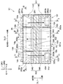
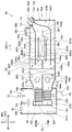
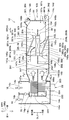
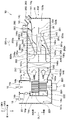
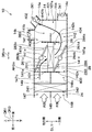
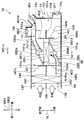
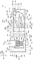
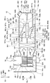
- FIG. 2 is a cross-sectional view showing a II-II cross section of FIG. 1 in the first embodiment.
- FIG. 3 is a cross-sectional view showing a III-III cross section of FIG. 2 in the first embodiment.
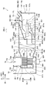
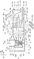
- FIG. 4 is a cross-sectional view showing the IV-IV cross section of FIG. 2 in the first embodiment, and is a view showing a maximum cooling state of the air conditioning unit. It is sectional drawing which showed the same cross section as FIG.
- the air conditioning unit 10 shown in FIG. 1 is a vehicle air conditioning unit mounted on a vehicle.
- the air conditioning unit 10 constitutes a part of a vehicle air conditioner provided with a refrigeration cycle including a compressor, a condenser and the like disposed in an engine room.
- the air conditioning unit 10 is arranged inside an instrument panel (not shown) provided on the front side of the vehicle interior.
- the air conditioning unit 10 sucks one or both of the inside air, which is the air inside the vehicle interior, and the outside air, which is the air outside the vehicle interior, and regulates the sucked air and blows it out into the vehicle interior.
- the air conditioning unit 10 performs air conditioning in the predetermined space 12 in the vehicle interior.
- the air conditioning unit 10 has an internal / external air two-layer function capable of separating the internal air and the external air and simultaneously blowing them out from different air outlets.
- the predetermined space 12 is illustrated only in FIG. 1, and the predetermined space 12 is not illustrated in other drawings.
- the air conditioning unit 10 includes an air conditioning case 14, an inside air introduction door 16, an outside air introduction door 18, a communication door 20, a blower 22, a cooler 24, a heater 26, and a plurality of opening / closing devices 28, 30, 32. And a plurality of outlet doors 341, 342, 361, 362, 363, 364, 381, 382 and the like.
- the cooler 24 is included in the air conditioning unit 10 and is also included in the refrigeration cycle. Further, for example, electric actuators are connected to the doors of the air conditioning unit 10, and the doors are operated by the electric actuators.
- FIG. 1 is a diagram showing a schematic configuration of the air conditioning unit of the present embodiment, and more specifically, a sectional view taken along the line II in FIG. 2 is the same as that taken along the line II.
- FIG. 1 the code of the element appearing in the Ic-Ic cross section is shown together with the code of the element appearing in the II cross section. Has been.
- arrows DR1 and DR3 in FIG. 1 and arrow DR2 in FIG. 2 indicate the direction of the vehicle on which the air conditioning unit 10 is mounted. That is, the arrow DR1 indicates the vehicle vertical direction DR1, the arrow DR2 indicates the vehicle width direction DR2 (that is, the vehicle left-right direction DR2), and the arrow DR3 indicates the vehicle longitudinal direction DR3. These three directions DR1, DR2, DR3 are directions intersecting each other, strictly speaking, directions orthogonal to each other.
- the air conditioning case 14 forms a casing of the air conditioning unit 10.
- the air conditioning case 14 is formed of a resin having a certain degree of elasticity, such as polypropylene, and having excellent mechanical strength. As shown in FIGS. 1 to 3, the air conditioning case 14 is formed with an inside air introduction port 14a and an outside air introduction port 14b as suction ports for sucking air.
- the air-conditioning case 14 includes two foot outlets 14c and 14d, four face outlets 14e, 14f, 14g, and 14h, and two defroster outlets 14i and 14j as outlets for blowing out air. Has been. In FIGS. 2 and 3, the blowout door is not shown.
- FIG. 3 is a cross-sectional view showing the III-III cross section of FIG. Accordingly, the air outlets 14e, 14f, 14g, 14h, 14i, and 14j are not actually shown in FIG. 3, but are shown in FIG. 3 by a two-dot chain line in order to show the arrangement of the air outlets in the vehicle width direction DR2. ing.
- a first introduction passage 14k, a second introduction passage 14m, a first air passage 141, a second air passage 142, a third air passage 143, and a fourth air passage 144 are provided as ventilation passages through which air flows.
- a fifth air passage 145, a sixth air passage 146, a first upstream air passage 147, and a second upstream air passage 148 are formed.
- a first fan chamber 14n in which the first fan 221 of the blower 22 is accommodated, a second fan chamber 14o in which the second fan 222 of the blower 22 is accommodated, and an inside / outside air communication hole 14p is formed.
- the inside air introduction port 14a opens into the vehicle interior. That is, the inside air introduction port 14 a is an opening for introducing inside air into the air conditioning case 14.
- An inside air introduction door 16 is provided in the inside air introduction port 14a, and the inside air introduction door 16 opens and closes the inside air introduction port 14a.
- the outside air inlet 14b opens to the outside of the passenger compartment. That is, the outside air introduction port 14 b is an opening for introducing outside air into the air conditioning case 14. The outside air and the inside air are air introduced from different locations.
- An outside air introduction door 18 is provided at the outside air introduction port 14b, and the outside air introduction door 18 opens and closes the outside air introduction port 14b.
- the first introduction passage 14k is a passage connecting the inside air introduction port 14a and the first fan chamber 14n.
- the first fan chamber 14n is connected to the first introduction passage 14k on the vehicle upper side of the first fan chamber 14n.
- the second introduction passage 14m is a passage connecting the outside air introduction port 14b and the second fan chamber 14o.
- the second fan chamber 14o is connected to the second introduction passage 14m on the vehicle lower side of the second fan chamber 14o.
- the inside / outside air communication hole 14p is a hole that allows the first introduction passage 14k and the second introduction passage 14m to communicate with each other.
- a communication door 20 is provided in the inside / outside air communication hole 14p, and the communication door 20 opens and closes the inside / outside air communication hole 14p. Therefore, for example, as shown in FIG. 1, when the outside air introduction port 14b is closed while the inside air introduction port 14a is opened and the inside / outside air communication hole 14p is opened, the inside air introduced from the inside air introduction port 14a. Flows into both the first introduction passage 14k and the second introduction passage 14m.
- the blower 22 includes a first fan 221, a second fan 222, a motor 223, and a rotating shaft 224. Both the first fan 221 and the second fan 222 are centrifugal fans, and are connected to the motor 223 via the rotating shaft 224. The motor 223 rotates the first fan 221 and the second fan 222 as a unit.
- the first upstream air passage 147 is connected to the first fan chamber 14n at the air flow upstream end 147a of the first upstream air passage 147.
- the second upstream air passage 148 is connected to the second fan chamber 14o at the air flow upstream end 148a of the second upstream air passage 148.
- the blower 22 sucks air from the first introduction passage 14k into the first fan 221 by the rotation of the first fan 221, and the sucked air enters the first upstream air passage 147 as indicated by the arrow FL1. Blow out. At the same time, the blower 22 sucks air from the second introduction passage 14m into the second fan 222 by the rotation of the second fan 222, and draws the sucked air into the second upstream air passage 148 as indicated by the arrow FL2. To blow out.
- the second upstream air passage 148 is arranged side by side with respect to the first upstream air passage 147 to one side in the first arrangement direction DL1.
- the first arrangement direction DL1 coincides with the vehicle up-down direction DR1
- one side of the first arrangement direction DL1 is the lower side in the vehicle up-down direction DR1.
- the other side of the first arrangement direction DL1 is an upper side in the vehicle vertical direction DR1.
- the air conditioning case 14 includes an upstream partition 149 that separates the first upstream air passage 147 and the second upstream air passage 148.
- the first upstream air passage 147 is formed above the upstream partition 149, and the second upstream air passage 148 is formed below the upstream partition 149.
- the first to sixth air passages 141, 142, 143, 144, 145, and 146 are provided in parallel with each other.
- the first to sixth air passages 141 to 146 are all formed to extend in the passage extending direction DRrn that coincides with the vehicle longitudinal direction DR3. Air blown into the passenger compartment flows through the first to sixth air passages 141 to 146, respectively.
- the first to sixth air passages 141 to 146 constitute three passage groups 151, 152, and 153 because of their mutual connection. That is, the first air passage 141 and the second air passage 142 constitute a first passage group 151. Further, the third air passage 143 and the fourth air passage 144 constitute a second passage group 152. Further, the fifth air passage 145 and the sixth air passage 146 constitute a third passage group 153.
- the first passage group 151 is arranged side by side with respect to the second passage group 152 on one side of the second alignment direction DL2 that intersects the first alignment direction DL1.
- the third passage group 153 is arranged side by side with respect to the second passage group 152 on the other side in the second arrangement direction DL2.
- the second arrangement direction DL2 coincides with the vehicle width direction DR2.
- the second air passage 142 is arranged side by side with respect to the first air passage 141 on one side in the first arrangement direction DL1.
- the fourth air passage 144 is arranged side by side with respect to the third air passage 143 to the other side in the first arrangement direction DL1.
- the sixth air passage 146 is arranged side by side with respect to the fifth air passage 145 to one side in the first arrangement direction DL1.
- the air conditioning case 14 includes a first partition 154, a second partition 155, and a third partition 156.
- the 1st partition 154 is comprised by the flat form which made the vehicle up-down direction DR1 the thickness direction.
- the first partition 154 separates the first air passage 141 and the second air passage 142 in the first passage group 151, and separates the third air passage 143 and the fourth air passage 144 in the second passage group 152.
- the fifth air passage 145 and the sixth air passage 146 are separated by the third passage group 153.
- first air passage 141, the fourth air passage 144, and the fifth air passage 145 are formed above the first partition 154.
- the second air passage 142, the third air passage 143, and the sixth air passage 146 are formed below the first partition 154.
- the second partition wall 155 has a flat plate shape with the vehicle width direction DR2 as the thickness direction.
- the second partition 155 separates the first air passage 141 and the fourth air passage 144 and separates the second air passage 142 and the third air passage 143.
- the second partition 155 separates the first passage group 151 and the second passage group 152.
- first air passage 141 and the second air passage 142 are formed on one side of the second partition direction DL2 with respect to the second partition 155.
- third air passage 143 and the fourth air passage 144 are formed on the other side of the second alignment direction DL2 with respect to the second partition 155.
- the third partition wall 156 is configured in a flat plate shape with the vehicle width direction DR2 in the thickness direction, similar to the second partition wall 155.
- the third partition 156 separates the third air passage 143 and the sixth air passage 146 and separates the fourth air passage 144 and the fifth air passage 145 from each other.
- the second partition 155 separates the second passage group 152 and the third passage group 153.
- the third air passage 143 and the fourth air passage 144 are formed on one side in the second arrangement direction DL2 with respect to the second partition 155.
- the fifth air passage 145 and the sixth air passage 146 are formed on the other side of the second alignment direction DL2 with respect to the second partition 155.
- the first to sixth air passages 141 to 146 are provided on the downstream side of the first upstream air passage 147 and the second upstream air passage 148. Further, the upstream partition 149 and the first partition 154 are arranged so as to spread on a common plane.
- the first upstream air passage 147 is directed to the air flow upstream end 141a of the first air passage 141, the air flow upstream end 144a of the fourth air passage 144, and the air flow upstream end 145a of the fifth air passage 145, respectively.
- the second upstream air passage 148 is connected to the air flow upstream end 142a of the second air passage 142, the air flow upstream end 143a of the third air passage 143, and the air flow upstream end 146a of the sixth air passage 146, respectively. Communicate.
- a first group downstream communication space 157a, a second group downstream communication space 157b, and a third group downstream communication space 157c are formed.
- the first group downstream communication space 157 a is provided on the air flow downstream side of the first passage group 151.
- the first group downstream communication space 157 a is connected to the air flow downstream end 141 b of the first air passage 141 and the air flow downstream end 142 b of the second air passage 142.
- the second group downstream communication space 157 b is provided on the air flow downstream side of the second passage group 152.
- the second group downstream communication space 157 b is connected to the air flow downstream end 143 b of the third air passage 143 and the air flow downstream end 144 b of the fourth air passage 144.
- the third group downstream communication space 157 c is provided on the air flow downstream side of the third passage group 153.
- the third group downstream communication space 157 c is connected to the air flow downstream end 145 b of the fifth air passage 145 and the air flow downstream end 146 b of the sixth air passage 146.
- the second partition wall 155 is extended between the first group downstream communication space 157a and the second group downstream communication space 157b. Accordingly, the second partition 155 separates the first group downstream communication space 157a and the second group downstream communication space 157b in the vehicle width direction DR2.
- the third partition wall 156 extends to the space between the second group downstream communication space 157b and the third group downstream communication space 157c. Thereby, the third partition 156 separates the second group downstream communication space 157b and the third group downstream communication space 157c in the vehicle width direction DR2.
- the foot outlets 14c and 14d are outlets for blowing air out of the air conditioning case 14 toward the feet of passengers seated in the passenger compartment.
- the face air outlets 14e, 14f, 14g, and 14h are air outlets that blow out air from the air conditioning case 14 toward the head and chest of the occupant seated in the passenger compartment.
- the defroster outlets 14i and 14j are outlets for blowing air out of the air conditioning case 14 toward the inner surface of the front window of the vehicle.
- the first foot outlet 14c and the first face outlet 14e are connected to the first group downstream communication space 157a.
- a first foot outlet door 341 is provided at the first foot outlet 14c, and the first foot outlet door 341 opens and closes the first foot outlet 14c.
- the first face air outlet 14e is provided with a first face air outlet door 361, and the first face air outlet door 361 opens and closes the first face air outlet 14e.
- the second face air outlet 14f, the third face air outlet 14g, the first defroster air outlet 14i, and the second defroster air outlet 14j are connected to the second group downstream communication space 157b.
- a second face air outlet door 362 is provided at the second face air outlet 14f, and the second face air outlet door 362 opens and closes the second face air outlet 14f.
- a third face air outlet door 363 is provided at the third face air outlet 14g, and the third face air outlet door 363 opens and closes the third face air outlet 14g.
- a first defroster outlet door 381 is provided at the first defroster outlet 14i, and the first defroster outlet door 381 opens and closes the first defroster outlet 14i.
- a second defroster outlet door 382 is provided at the second defroster outlet 14j, and the second defroster outlet door 382 opens and closes the second defroster outlet 14j.
- the second foot outlet 14d and the fourth face outlet 14h are connected to the third group downstream communication space 157c.
- a second foot outlet door 342 is provided at the second foot outlet 14d, and the second foot outlet door 342 opens and closes the second foot outlet 14d.
- a fourth face air outlet door 364 is provided at the fourth face air outlet 14h, and the fourth face air outlet door 364 opens and closes the fourth face air outlet 14h.
- the cooler 24 is a heat exchanger for air cooling accommodated in the air conditioning case 14.
- the cooler 24 is an evaporator, which exchanges heat between the refrigerant circulating in the refrigeration cycle and the air passing through the cooler 24, evaporates the refrigerant by the heat exchange, and cools the air.
- the cooler 24 includes a first cooling unit 241 and a second cooling unit 242 that are integrally formed.
- the first cooling unit 241 is provided in the first upstream air passage 147 and cools the air flowing through the first upstream air passage 147.
- the second cooling unit 242 is provided in the second upstream air passage 148 and cools the air flowing through the second upstream air passage 148.
- the first upstream air passage 147 has a first communication space 147c on the downstream side of the air flow from the first cooling unit 241.
- An air flow upstream end 141a of the first air passage 141, an air flow upstream end 144a of the fourth air passage 144, and an air flow upstream end 145a of the fifth air passage 145 are connected to the first communication space 147c, respectively.
- the first communication space 147c connects the air flow upstream ends 141a, 144a, and 145a to each other.
- the air that has passed through the first cooling unit 241 can flow into any of the first air passage 141, the fourth air passage 144, and the fifth air passage 145.
- the second upstream air passage 148 has a second communication space 148c on the downstream side of the air flow from the second cooling part 242.
- An air flow upstream end 142a of the second air passage 142, an air flow upstream end 143a of the third air passage 143, and an air flow upstream end 146a of the sixth air passage 146 are connected to the second communication space 148c, respectively.
- the second communication space 148c connects the air flow upstream ends 142a, 143a, and 146a to each other.
- the air that has passed through the second cooling section 242 can flow into any of the second air passage 142, the third air passage 143, and the sixth air passage 146.
- the edge 155a on the cooler 24 side of the second partition 155 in the passage extending direction DRrn is in the passage extending direction DRrn.
- the end edge 156a of the third partition wall 156 on the cooler 24 side in the passage extending direction DRrn is also separated from the cooler 24 in the passage extending direction DRrn.
- the end edge 155a of the second partition wall 155 and the end edge 156a of the third partition wall 156 are both arranged so as not to protrude from the heater 26 to the cooler 24 side in the passage extending direction DRrn.
- the heater 26 is a heat exchanger for air heating accommodated in the air conditioning case 14.
- the heater 26 is a heater core, and exchanges heat between engine coolant heated by the engine and air passing through the heater 26, and heats the air passing therethrough through the heat exchange.
- the heater 26 includes a pair of header tanks 26a and 26b whose longitudinal direction is the vehicle width direction DR2, and a core portion 26c disposed between the header tanks 26a and 26b.
- the core portion 26c includes a plurality of tubes that are stacked in the vehicle width direction DR2 and allow engine coolant to flow from one to the other of the pair of header tanks 26a and 26b. And in the core part 26c, air is heated passing through the core part 26c.
- the heater 26 includes a first heating unit 261, a second heating unit 262, and a third heating unit 263.
- the air that enters and exits the first heating unit 261 and the air that enters and exits the second heating unit 262 are separated by the second partition 155, and the air that enters and exits the second heating unit 262 and the air that enters and exits the third heating unit 263 are third. It is divided by a partition 156.
- heating parts 261, 262, 263 are united to constitute a core part 26c. Moreover, all of these heating parts 261, 262, and 263 have a flat shape with the first arrangement direction DL1 as the thickness direction.
- the first heating unit 261 is disposed between the first air passage 141 and the second air passage 142 in the first arrangement direction DL1.
- the air inflow side into which the air of the first heating unit 261 flows is connected in the middle of the first air passage 141. That is, the first heating unit 261 is configured so that the air inflow surface 261a provided on the air inflow side of the first heating unit 261 faces the first air passage 141 side from the side of the first air passage 141.
- One air passage 141 is connected.
- the fact that the air inflow side of the first heating unit 261 is connected in the middle of the first air passage 141 means that a portion in the middle of the first air passage 141 is included in the connected connection range. is there. That is, the air flow upstream end 141a or the air flow downstream end 141b of the first air passage 141 may be included in the connection range.
- the air outflow side from which the air of the first heating unit 261 flows out is connected in the middle of the second air passage 142. That is, the first heating unit 261 is configured so that the air outflow surface 261b provided on the air outflow side of the first heating unit 261 faces the second air passage 142 from the side of the second air passage 142. Two air passages 142 are connected.
- the first heating unit 261 when the first path which is the path of air passing through the first heating unit 261 is opened, the first heating unit 261 is connected to the first air path 141 in the middle of the first air path 141. Air flows in as shown by the arrow FLa in FIG. Then, the first heating unit 261 heats the inflowed air and causes it to flow out into the second air passage 142. In short, when the first path is open, the first heating unit 261 flows the air passing through the first heating unit 261 from the other side of the first arrangement direction DL1 to the one side while heating the air. . In other words, the direction of the air flow passing through the first heating unit 261 intersects the passage extending direction DRrn.
- the air passage to which the air inflow side of the first heating unit 261 is connected is defined as the first one passage, and the air outflow side of the first heating unit 261 is connected. It is assumed that the air passage to be defined is defined as the first other passage. In this case, the first air passage 141 corresponds to the first one passage, and the second air passage 142 corresponds to the first other passage.
- the second heating unit 262 is disposed between the third air passage 143 and the fourth air passage 144 in the first arrangement direction DL1.
- the air inflow side of the second heating unit 262 is connected in the middle of the third air passage 143. That is, the second heating unit 262 is arranged such that the air inflow surface 262a provided on the air inflow side of the second heating unit 262 faces the third air passage 143 from the side of the third air passage 143. Three air passages 143 are connected.
- the air outflow side of the second heating unit 262 is connected in the middle of the fourth air passage 144. That is, the second heating unit 262 is arranged so that the air outflow surface 262b provided on the air outflow side of the second heating unit 262 faces the fourth air passage 144 from the side of the fourth air passage 144. 4 is connected to the air passage 144.
- the second heating unit 262 when the second path, which is the path of air passing through the second heating unit 262, is opened, the second heating unit 262 is connected to the third air path 141 in the middle of the third air path 143. Air flows in as shown by the arrow FLb in FIG. And the 2nd heating part 262 heats the inflowed air, and makes it flow out in the middle of the 4th air channel
- FIG. when the second path is open, the second heating unit 262 flows the air passing through the second heating unit 262 from one side to the other side in the first arrangement direction DL1 while heating the air. . In other words, the direction of the air flow passing through the second heating unit 262 intersects the passage extending direction DRrn.
- the air passage to which the air inflow side of the second heating unit 262 is connected is defined as the second one passage, and the air outflow side of the second heating unit 262 is connected.
- the air passage to be defined is defined as the second other passage.
- the third air passage 143 corresponds to the second one passage
- the fourth air passage 144 corresponds to the second other passage.
- the third heating unit 263 is disposed between the fifth air passage 145 and the sixth air passage 146 in the first arrangement direction DL1.
- the air inflow side of the third heating unit 263 is connected in the middle of the fifth air passage 145. That is, the third heating unit 263 is configured such that the air inflow surface 263a provided on the air inflow side of the third heating unit 263 faces the fifth air passage 145 from the side of the fifth air passage 145. 5 is connected to the air passage 145.
- the air outflow side of the third heating unit 263 is connected to the middle of the sixth air passage 146. That is, the third heating unit 263 is arranged so that the air outflow surface 263b provided on the air outflow side of the third heating unit 263 faces the sixth air passage 146 from the side of the sixth air passage 146. 6 air passages 146 are connected.
- the third heating unit 263 is connected to the fifth air path 145 from the fifth air path 145. Air flows in as shown by the arrow FLc in FIG. And the 3rd heating part 263 heats the inflowed air, and makes it flow out in the middle of the 6th air channel
- FIG. when the third path is open, the third heating unit 263 flows the air passing through the third heating unit 263 from the other side of the first arrangement direction DL1 to the one side while heating the air. . In other words, the direction of the air flow passing through the third heating unit 263 intersects the passage extending direction DRrn.
- the air passage connected to the air inflow side of the third heating unit 263 is defined as a third one passage, and the air outflow side of the third heating unit 263 is connected. It is assumed that the air passage to be defined is defined as the third other passage. In this case, the fifth air passage 145 corresponds to the third one passage, and the sixth air passage 146 corresponds to the third other passage.
- the third passage group 153 is compared with the first passage group 151, the two passage groups 151 and 153 have the same configuration.
- the fifth air passage 145 corresponds to the first air passage 141
- the sixth air passage 146 corresponds to the second air passage 142.
- the third heating unit 263 corresponds to the first heating unit 261
- the third opening / closing device 32 corresponds to the first opening / closing device 28.
- the second foot outlet 14d corresponds to the first foot outlet 14c
- the fourth face outlet 14h corresponds to the first face outlet 14e.
- the first opening / closing device 28 opens and closes a first path that is a path of air passing through the first heating unit 261.
- the first opening / closing device 28 functions as a first temperature adjusting device that adjusts the temperature of the air blown out from the first passage group 151. That is, the first opening / closing device 28 adjusts the ratio of the air heated by the first heating unit 261 out of the air flowing into the first passage group 151 by increasing or decreasing the opening degree of the first path.
- the first opening / closing device 28 includes a first inflow side door portion 281 that opens and closes the air inflow side of the first heating unit 261 and a first outflow side door portion that opens and closes the air outflow side of the first heating unit 261. 282.
- the first inflow side door 281 opens the air inflow side of the first heating unit 261 and the first outflow side door 282 opens the air outflow side of the first heating unit 261, thereby opening the first path. It is. Thereby, the air which flowed out from the 1st upstream air passage 147 flows into the 1st course. Conversely, the first inflow side door part 281 closes the air inflow side of the first heating part 261 and the first outflow side door part 282 closes the air outflow side of the first heating part 261, so that the first path is Closed.
- the first inflow side door portion 281 and the first outflow side door portion 282 are opened and closed in conjunction with each other. That is, when the first inflow side door 281 opens the air inflow side of the first heating unit 261, the first outflow side door 282 opens the air outflow side of the first heating unit 261. When the first inflow side door portion 281 closes the air inflow side of the first heating unit 261, the first outflow side door portion 282 closes the air outflow side of the first heating unit 261.
- the first inflow side door portion 281 can be switched between a passage closed state shown in FIG. 5 and a heating portion closed state shown in FIG.
- the first inflow side door portion 281 separates the connection portion 141c to which the air inflow side of the first heating portion 261 is connected in the first air passage 141 and the air flow downstream side from the connection portion 141c.
- the first air passage 141 is closed.
- the first inflow side door part 281 opens the air inflow side of the first heating part 261.
- the first inflow side door portion 281 opens the first air passage 141 and closes the air inflow side of the first heating portion 261 when the heating portion is closed.
- the first inflow side door portion 281 includes a plate-like door member 281 a and a door rotation shaft 281 b connected to one end of the door member 281 a.
- the door rotation shaft 281b is arranged downstream of the core portion 26c of the heater 26 in the air flow direction of the first air passage 141, and the axial direction of the door rotation shaft 281b faces the vehicle width direction DR2. Yes.
- the door member 281a of the first inflow side door portion 281 covers the air inflow surface 261a of the first heating portion 261 when the first inflow side door portion 281 closes the air inflow side of the first heating portion 261. .
- the door member 281a is as shown in FIG. 5 when the first inflow side door portion 281 is closed. That is, in the passage closed state, the door member 281a moves in the passage extending direction DRrn so that the air flowing upstream of the first heating unit 261 in the first air passage 141 is guided to the first heating unit 261. Inclines against.
- the first outflow side door portion 282 can be switched between a passage closed state shown in FIG. 5 and a heating portion closed state shown in FIG. In the closed state of the passage, the first outflow side door portion 282 separates the connection location 142c where the air outflow side of the first heating portion 261 is connected in the second air passage 142 and the upstream side of the air flow from the connection location 142c. The second air passage 142 is closed. At the same time, the first outflow side door 282 opens the air outflow side of the first heating unit 261.
- the first outflow side door section 282 opens the second air passage 142 and closes the air outflow side of the first heating section 261 in the heating section closed state.
- the first outflow side door portion 282 includes a plate-like door member 282a and a door rotation shaft 282b connected to one end of the door member 282a.
- the door rotation shaft 282b is disposed upstream of the core portion 26c of the heater 26 in the air flow direction of the second air passage 142, and the axial direction of the door rotation shaft 282b faces the vehicle width direction DR2. Yes.
- the door member 282a of the first outflow side door 282 covers the air outflow surface 261b of the first heating unit 261 when the first outflow side door 282 closes the air outflow side of the first heating unit 261. .
- the door member 282a is as shown in FIG. 5 when the first outflow side door portion 282 is closed. That is, in the passage closed state, the door member 282a is inclined with respect to the passage extending direction DRrn so as to guide the air flowing out from the first heating unit 261 to the air flow downstream side of the second air passage 142.
- the second opening / closing device 30 opens and closes a second path that is a path of air passing through the second heating unit 262.
- the second opening / closing device 30 functions as a second temperature adjusting device that adjusts the temperature of the air blown out from the second passage group 152. That is, the second opening / closing device 30 adjusts the ratio of the air heated by the second heating unit 262 in the air flowing into the second passage group 152 by increasing or decreasing the opening degree of the second path.
- the second opening / closing device 30 includes a second inflow side door 301 that opens and closes the air inflow side of the second heating unit 262 and a second outflow side door that opens and closes the air outflow side of the second heating unit 262. 302.
- the second inflow side door part 301 opens the air inflow side of the second heating part 262 and the second outflow side door part 302 opens the air outflow side of the second heating part 262, thereby opening the second path. It is. Thereby, the air which flowed out from the 2nd upstream air passage 148 flows into the 2nd course. Conversely, when the second inflow side door portion 301 closes the air inflow side of the second heating unit 262 and the second outflow side door portion 302 closes the air outflow side of the second heating unit 262, the second path is Closed.
- the second inflow side door portion 301 and the second outflow side door portion 302 are opened and closed in conjunction with each other. That is, when the second inflow side door part 301 opens the air inflow side of the second heating part 262, the second outflow side door part 302 opens the air outflow side of the second heating part 262. Further, when the second inflow side door part 301 closes the air inflow side of the second heating part 262, the second outflow side door part 302 closes the air outflow side of the second heating part 262.
- the second inflow side door portion 301 can be switched between a passage closed state shown in FIG. 6 and a heated portion closed state shown in FIG. In the closed state of the passage, the second inflow side door portion 301 separates the connection location 143c where the air inflow side of the second heating portion 262 is connected in the third air passage 143 and the downstream side of the air flow from the connection location 143c. The third air passage 143 is closed. At the same time, the second inflow side door part 301 opens the air inflow side of the second heating part 262.
- the second inflow side door portion 301 opens the third air passage 143 and closes the air inflow side of the second heating portion 262 in the heated portion closed state.
- the second inflow side door portion 301 includes a plate-shaped door member 301a and a door rotation shaft 301b connected to one end of the door member 301a.
- the door rotation shaft 301b is disposed downstream of the core portion 26c of the heater 26 in the air flow direction of the third air passage 143, and the axial direction of the door rotation shaft 301b faces the vehicle width direction DR2.
- the door member 301a of the second inflow side door portion 301 covers the air inflow surface 262a of the second heating portion 262 when the second inflow side door portion 301 closes the air inflow side of the second heating portion 262. .
- the door member 301a is as shown in FIG. 6 when the second inflow side door portion 301 is closed. That is, in the passage closed state, the door member 301a moves in the passage extending direction DRrn so that the air flowing upstream of the second heating unit 262 in the third air passage 143 is guided to the second heating unit 262. Inclines against.
- the second outflow side door portion 302 can be switched between a passage closed state shown in FIG. 6 and a heated portion closed state shown in FIG. In the closed state of the passage, the second outflow side door 302 separates the connection location 144c where the air outflow side of the second heating unit 262 is connected in the fourth air passage 144 from the upstream side of the air flow from the connection location 144c. The fourth air passage 144 is closed. At the same time, the second outflow side door portion 302 opens the air outflow side of the second heating unit 262.
- the second outflow side door section 302 opens the fourth air passage 144 and closes the air outflow side of the second heating section 262 in the heated section closed state.
- the second outflow side door portion 302 includes a plate-like door member 302a and a door rotation shaft 302b connected to one end of the door member 302a.
- the door rotation shaft 302b is arranged upstream of the core portion 26c of the heater 26 in the air flow direction of the fourth air passage 144, and the axial direction of the door rotation shaft 302b faces the vehicle width direction DR2. Yes.
- the door member 302a of the second outflow side door portion 302 covers the air outflow surface 262b of the second heating unit 262 when the second outflow side door unit 302 closes the air outflow side of the second heating unit 262. .
- the door member 302a is as shown in FIG. 6 when the second outflow side door portion 302 is closed. That is, in the passage closed state, the door member 302a is inclined with respect to the passage extending direction DRrn so as to guide the air flowing out from the second heating unit 262 to the downstream side of the air flow of the fourth air passage 144.
- the third opening / closing device 32 opens and closes a third path that is a path of air passing through the third heating unit 263. Since the third opening / closing device 32 corresponds to the first opening / closing device 28 as described above, the third path corresponds to a first path opened / closed by the first opening / closing device 28.
- the third inflow side door portion 321 of the third opening / closing device 32 corresponds to the first inflow side door portion 281 and includes a door member 321a and a door rotation shaft 321b. Therefore, the 3rd inflow side door part 321 can be switched to the passage obstruction
- the third outflow side door portion 322 of the third opening / closing device 32 corresponds to the first outflow side door portion 282, and includes a door member 322a and a door rotation shaft 322b.
- the third inflow side door portion 321 and the third outflow side door portion 322 are similar to the first inflow side door portion 281 and the first outflow side door portion 282, respectively, as shown in FIG. It can switch to the heating part obstruction
- the first opening / closing device 28, the second opening / closing device 30, and the third opening / closing device 32 open / close in conjunction with each other.
- the first opening / closing device 28 opens the first route
- the second opening / closing device 30 opens the second route
- the third opening / closing device 32 opens the third route.
- the first switch 28 closes the first path
- the second switch 30 closes the second path
- the third switch 32 closes the third path.
- the air flow downstream side of the upstream air passages 147 and 148 in the air conditioning unit 10 includes the first to third air conditioning layers 101, 102, and 103 stacked in three layers in the second arrangement direction DL2.
- the first air-conditioning layer 101 among the air-conditioning layers stacked in the three layers includes a first air passage 141, a second air passage 142, a first heating unit 261, a first heating portion 261, as shown in FIGS.
- the first opening / closing device 28, the first group downstream communication space 157a, the air outlets 14c and 14e, and the air outlet doors 341 and 361 are configured.
- the second air-conditioning layer 102 includes the third air passage 143, the fourth air passage 144, the second heating unit 262, the second opening / closing device 30, and the second group downstream communication space 157b. , Air outlets 14f, 14g, 14i, 14j, and air outlet doors 362, 363, 381, 382.
- the third air conditioning layer 103 includes a fifth air passage 145, a sixth air passage 146, a third heating unit 263, a third opening / closing device 32, and a third group downstream communication space 157c.
- the air outlets 14d and 14h and the air outlet doors 342 and 364 are included.
- the air conditioning unit 10 performs air conditioning operation in various operating states. For example, in the operation state in which the air conditioning unit 10 cools most strongly, that is, in the maximum cooling state of the air conditioning unit 10 (in other words, the MAXCOOL state), the blower 22 blows air with a predetermined air flow rate that realizes the maximum cooling state. .
- the inside air introduction door 16 opens the inside air introduction port 14a
- the outside air introduction door 18 closes the outside air introduction port 14b
- the communication door 20 opens the inside / outside air communication hole 14p.
- the face outlets 14e, 14f, 14g and 14h are all opened, while the foot outlets 14c and 14d and the defroster outlets 14i and 14j are all closed.
- the first to third inflow side door portions 281, 301, and 321 and the first to third outflow side door portions 282, 302, and 322 are all in the heating portion closed state.
- the inside air is introduced into the first and second upstream air passages 147 and 148.
- the inside air cooled by the first cooling unit 241 flows into the first air passage 141, the fourth air passage 144, and the fifth air passage 145.
- the inside air cooled by the second cooling unit 242 flows into the second air passage 142, the third air passage 143, and the sixth air passage 146.
- the inside air that has flowed into the first air passage 141 passes through the first air passage 141 as indicated by the arrow AC1 in FIG. 1, and the inside air that has flowed into the second air passage 142 is the second air passage 142 as indicated by the arrow AC2. Pass through. Both the inside air passes through the first group downstream communication space 157a and is blown out from the first face outlet 14e into the vehicle interior.
- the air flow in the fifth air passage 145 and the sixth air passage 146 is similar to this.
- the inside air that has flowed into the third air passage 143 passes through the third air passage 143 as indicated by an arrow AC3 in FIG. 4, and the inside air that has flowed into the fourth air passage 144 is indicated by an arrow AC4 as indicated by an arrow AC4. Pass through 144. Both the inside air is blown out from the second face outlet 14f and the third face outlet 14g through the second group downstream communication space 157b into the vehicle interior.
- the passages facing the heater 26, that is, the first to sixth air passages 141 to 146 are all air cooled by the cooler 24. Functions as a cold air passage that flows without passing through the heater 26.
- the air inflow surface 261a facing the first air passage 141 side of the first heating unit 261 has a direction of air flow in the first air passage 141 when the first path is closed (in other words, air Along the flow direction).
- the air inflow surface 262a facing the third air passage 143 side of the second heating unit 261 is along the direction of the air flow in the third air passage 143 when the second path is closed.
- the air outflow surface 262b which faced the 4th air passage 144 side among the 2nd heating parts 261 is along the direction of the air flow of the 4th air passage 144 in the case where the said 2nd path
- the air conditioning unit 10 performs the air conditioning operation in the maximum heating state (in other words, the MAXHOT state) as an operation state different from the above maximum cooling state.
- the maximum heating state of the air conditioning unit 10 is an operation state in which the air conditioning unit 10 performs heating most strongly.
- the blower 22 blows air with a predetermined air volume that realizes the maximum heating state.
- the inside air introduction door 16 opens the inside air introduction port 14a
- the outside air introduction door 18 opens the outside air introduction port 14b
- the communication door 20 closes the inside / outside air communication hole 14p.
- the 1st face blower outlet 14e and the 4th face blower outlet 14h are closed.
- the second face outlet 14f and the third face outlet 14g are opened, and the foot outlets 14c and 14d and the defroster outlets 14i and 14j are all opened.
- the first to third inflow side door portions 281, 301, 321 and the first to third outflow side door portions 282, 302, 322 are all closed.
- the inside air is introduced into the first upstream air passage 147 and the outside air is introduced into the second upstream air passage 148. That is, the air flowing through the upstream air passages 147 and 148 is divided into two layers of the inside air and the outside air by the upstream partition 149.
- the air conditioning unit 10 is in a two-layered state in which the inside air and the outside air are separated and circulates in the air conditioning unit 10.
- the inside air flowing into the first air passage 141 flows through the first air passage 141 as indicated by an arrow AH1a in FIG. 5, flows into the first heating unit 261 from the air inflow surface 261a, and moves the first heating unit 261 upward. Is heated by the first heating unit 261 while passing downward.
- the heated inside air flows out from the air outflow surface 261b as indicated by an arrow AH1b, and blows out from the first foot outlet 14c through the second air passage 142 into the vehicle interior.
- the air flow in the fifth air passage 145 and the sixth air passage 146 is similar to this.
- outside air flows out from the second upstream air passage 148.
- the second air passage 142 is connected to the connection portion 142c to which the air outflow side of the first heating unit 261 is connected and the air flow upstream end 142a. Is closed by the first outflow side door portion 282. Therefore, since the outside air flowing out from the second upstream air passage 148 cannot pass through the second air passage 142, it is guided to the third air passage 143 through the second communication space 148c.
- the outside air flowing into the third air passage 143 from the second upstream air passage 148 flows through the third air passage 143 as indicated by an arrow AH2a in FIG. 6, and then flows into the second heating unit 262 from the air inflow surface 262a. .
- the outside air flowing into the second heating unit 262 is heated by the second heating unit 262 while passing through the second heating unit 262 from the lower side to the upper side.
- the heated outside air flows out from the air outflow surface 262b as indicated by an arrow AH2b, passes through the fourth air passage 144, and the second and third face outlets 14f and 14g and the first and second defroster outlets 14i, 14j is blown out into the passenger compartment.
- the inside air flows out from the first upstream air passage 147.
- the fourth air passage 144 is connected to the connection portion 144c to which the air outflow side of the second heating unit 262 is connected and the upstream end of the air flow. 144a is closed by the second outflow side door portion 302. For this reason, since the inside air flowing out from the first upstream air passage 147 cannot pass through the fourth air passage 144, it is guided to the first air passage 141 and the fifth air passage 145 through the first communication space 147c.
- the inside air and the outside air are heated by the heater 26.
- the second partition 155 and the third partition 156 are alternately separated on the downstream side of the air flow. That is, the inside air space in which the inside air circulates and the outside air space in which the outside air circulates are arranged in the vehicle width direction DR2 on the downstream side of the air flow from the heater 26. Then, on the downstream side of the air flow from the heater 26, the inside air space and the outside air space respectively have a layer shape intersecting with the header tanks 26a, 26b whose longitudinal direction is the vehicle width direction DR2 in relation to the heater 26. Make it.
- the air conditioning unit 10 operates as an operation state different from the maximum cooling state and the maximum heating state, for example, by setting the opening degrees of the heating units 261, 262, and 263 of the heater 26 to the maximum cooling state and the maximum heating state.
- the air-conditioning operation is performed even in the operation state in the middle of the opening degree.
- the opening degrees of the heating units 261, 262, and 263 are defined, for example, with the opening degree in the maximum cooling state being 0% and the opening degree in the maximum heating state being 100%.
- FIG. 7 shows a state of the air conditioning unit 10 in which the opening degree of the second heating unit 262 is about 50%.
- FIG. 7 is a diagram for explaining the air flow in the second passage group 152. is there.
- the inside air is introduced into the first and second upstream air passages 147 and 148 as in the maximum cooling state of the air conditioning unit 10.
- the inside air cooled by the cooler 24 flows into both the third air passage 143 and the fourth air passage 144.
- the inside air flowing into the second heating unit 262 as indicated by the arrow AM3a is heated by the second heating unit 262 while passing through the second heating unit 262 from the lower side to the upper side.
- the heated inside air passes through the fourth air passage 144 from the air outflow surface 262b of the second heating unit 262 and the second and third face outlets 14f and 14g and the first and second defrosters as indicated by an arrow AM3b.
- the air is blown out from the air outlets 14i and 14j into the passenger compartment.
- the heated inside air flowing as shown by the arrow AM3b does not pass through the third air passage 143 as shown by the arrow AM1 without passing through the second heating unit 262, and without passing through the second heating unit 262.
- the air is blown into the vehicle interior.
- the air flow indicated by the arrows AM1, AM2, and AM3b becomes an air flow in which the warm air that is the inside air after heating is sandwiched between the cool air and the downstream side of the second outflow side door portion 302.
- the mixability of the warm air and cold air becomes favorable, and the temperature controllability of the conditioned air blown out by the air conditioning unit 10 is improved.
- the first heating unit 261 has an air inflow surface 261 a of the first heating unit 261, and the first path has the first path. It arrange
- the second heating unit 262 is arranged so that the air inflow surface 262a of the second heating unit 262 follows the direction of the air flow in the third air passage 143 when the second path is closed. Yes.
- the third heating unit 263 is arranged such that the air inflow surface 263a of the 31st heating unit 263 is along the direction of the air flow in the fifth air passage 145 when the third path is closed. Yes.
- a cold air passage that bypasses the heating units 261, 262, and 263 and a hot air passage (in other words, a warm air passage) that flows air to the heating units 261, 262, and 263 are arranged in parallel.
- the first to sixth air passages 141 to 146 function as hot air passages in the maximum heating state and function as cold air passages in the maximum cooling state, respectively. Therefore, it is possible to downsize the air conditioning unit 10 in the first arrangement direction DL1.
- the outer shape of the air conditioning unit 10 since the outer shape of the air conditioning unit 10 has a margin in the first arrangement direction DL1, it is possible to secure a large cold air passage area in each of the first to sixth air passages 141 to 146. As a result, it is possible to reduce the pressure loss by the air flow in the first to sixth air passages 141 to 146.
- the air conditioning unit 10 has the internal air flowing into the first upstream air passage 147 and the second upstream air passage 148 only in the maximum heating state.
- the inside / outside air two-layer state in which the outside air flows is set. Therefore, if the introduction of the inside and outside air is controlled in this way, the pressure loss can be reduced by the air flow in the first to sixth air passages 141 to 146 when the air conditioning operation is performed in a state other than the maximum heating state. Is possible.
- the opening / closing devices 28, 30, and 32 open the first to sixth air passages 141 to 146 most widely, so that the pressure loss is greatly reduced in the air flow in the maximum cooling state. Is possible.
- each of the opening / closing devices 28, 30, 32 has a function of closing the air passages 141 to 146 provided with the opening / closing devices 28, 30, 32 in the middle of the passage. Therefore, in the path up to the introduction of air into the cooler 24, it is only necessary to provide the first and second upstream air passages 147 and 148 as air passages for realizing the inside / outside air two-layer function. Therefore, the air passage from the blower 22 to the cooler 24 can be simply configured.
- the third air passage 143 flows into the first air passage 141 and the fifth air passage 145. Air introduced from a location different from air flows. In short, outside air flows into the third air passage 143, and inside air flows into the first air passage 141 and the fifth air passage 145. Therefore, the inside air and outside air can be separately used for air conditioning.
- the inflow side door portions 281, 301, 321 and the outflow side doors of the first to third closing devices 28, 30, 32 are provided. Any of the sections 282, 302, and 322 can be switched between the passage closed state and the heating section closed state. Accordingly, the first to sixth air passages 141 to 146 and the heater 26 are heated by flowing air to each of the first to third heating units 261, 262, and 263 while suppressing the space occupied by the heater 26 in the first arrangement direction DL1. Is possible.
- the second opening / closing device 30 when the first opening / closing device 28 opens a path of air passing through the first heating unit 261 (that is, the first path), the second opening / closing device 30 includes the second heating unit. Open the path of air passing through 262 (ie, the second path). Further, when the first opening / closing device 28 closes the first path, the second opening / closing device 30 closes the second path. Therefore, heating on / off using the first heating unit 261 and heating on / off using the second heating unit 262 can be linked.
- the first upstream air passage 147 has the first communication space 147c on the downstream side of the air flow from the first cooling unit 241.
- the first communication space 147c connects the air flow upstream end 141a of the first air passage 141, the air flow upstream end 144a of the fourth air passage 144, and the air flow upstream end 145a of the fifth air passage 145 to each other.
- the second upstream air passage 148 has a second communication space 148c on the downstream side of the air flow from the second cooling unit 242.
- the second communication space 148c connects the air flow upstream end 142a of the second air passage 142, the air flow upstream end 143a of the third air passage 143, and the air flow upstream end 146a of the sixth air passage 146 to each other.
- the second air passage 142 when the second air passage 142 is closed by the first outflow side door portion 282 and the sixth air passage 146 is closed by the third outflow side door portion 322, the second air passage 142 flows out of the second cooling portion 242. Air can flow to the third air passage 143.
- the fourth air passage 144 is closed by the second outflow side door portion 302, the air flowing out from the first cooling portion 241 can flow to the first air passage 141 and the fifth air passage 145. Is possible.
- the air conditioning case 14 includes the first partition 154, the second partition 155, and the third partition 156.
- the second partition 155 and the third partition 156 are parallel to each other, and the first partition 154 intersects the second partition 155 and the third partition 156, respectively. Accordingly, the first to sixth air passages 141 to 146 can be arranged close to each other, and the air conditioning unit 10 can be easily downsized.
- the first heating unit 261 causes the air passing through the first heating unit 261 to flow from the other side of the first arrangement direction DL1 to one side as indicated by an arrow FLa in FIG. .
- the 2nd heating part 262 flows the air which passes the 2nd heating part 262 from the one side of the 1st arrangement direction DL1 to the other side like the arrow FLb of FIG.
- the 3rd heating part 263 flows the air which passes the 3rd heating part 263 from the other side of the 1st arrangement direction DL1 to one side like arrow FLc of Drawing 2.
- the air that flows out from the first upstream air passage 147 and the air that flows out from the second upstream air passage 148 are separated while suppressing the width that the heater 26 occupies in the first arrangement direction DL1. Heating can be performed by each of the heating unit 261, the second heating unit 262, and the third heating unit 263.
- the inside air is introduced into the first upstream air passage 147, and the second upstream air passage 148 is introduced. Outside air is introduced.
- one side of the first arrangement direction DL1 is the lower side of the vehicle, and the other side of the first arrangement direction DL1 is the upper side of the vehicle.
- the first, fourth, and fifth air passages 141, 144, and 145 are disposed on the upper side with respect to the second, third, and sixth air passages 142, 143, and 146, respectively.
- the air-conditioning case 14 can be configured to easily guide the inside air heated by the first and third heating units 261 and 263 to the foot outlets 14c and 14d.
- the air conditioning case 14 can be configured to easily guide the outside air heated by the second heating unit 262 to the defroster outlets 14i and 14j.
- each door portion 283, 284 of the first opening / closing device 28 in the first air-conditioning layer 101 has a double opening structure that opens on both sides in the passage extending direction DRrn. Further, the first air conditioning layer 101 is provided with a first foot outlet 14c, a first face outlet 14e, and a first defroster outlet 14k.
- An outlet door 383 is also provided.
- the second air conditioning layer 102 and the third air conditioning layer 103 are configured in the same manner as the first air conditioning layer 101. Therefore, it is possible to switch the air blown out to the inside air or the outside air at each of the foot outlet, the face outlet, and the defroster outlet of the air conditioning case 14.
- the present embodiment is different from the first embodiment in this respect.
- the illustration of the air flow upstream side of the cooler 24 is omitted.
- the air flow upstream side of the cooler 24 is in the same state as in FIG. It has become. That is, inside air is introduced into the first upstream air passage 147 and outside air is introduced into the second upstream air passage 148.
- FIG. 8 and 9 show a face blowing mode in which the first face outlet 14e is opened and the first foot outlet 14c and the first defroster outlet 14k are closed.
- This is merely an example of the blowout mode, and in the first air-conditioning layer 101, any one of the plurality of blowout ports 14c, 14e, and 14k can be opened.
- the same applies to the second air conditioning layer 102 and the third air conditioning layer 103.
- air may pass through the first heating unit 261 from one side to the other side in the first arrangement direction DL ⁇ b> 1, In some cases, air passes from the other side of the first arrangement direction DL1 to one side.
- the first surface 261c side of the first heating unit 261 connected in the middle of the first air passage 141 becomes the air inflow side
- the first heating unit 261 connected in the middle of the second air passage 142 is used.
- the other surface 261d side of the heating unit 261 is an air outflow side.
- the one surface 261c side of the first heating unit 261 is the air outflow side
- the other surface 261d side of the first heating unit 261 is the air inflow side.
- the air that flows in from the one surface 261c side of the first heating unit 261 may flow out from the other surface 261d side of the first heating unit 261, or In some cases, air flowing in from the other surface 261d side flows out from the one surface 261c side of the first heating unit 261.
- the one surface 261c of the first heating unit 261 is a surface facing the first air passage 141 side among the two surfaces 261c and 261d through which the air of the first heating unit 261 passes. Further, the other surface 261d of the first heating unit 261 is a surface facing the second air passage 142 side among the two surfaces 261c and 261d through which the air of the first heating unit 261 passes.
- the first opening / closing device 28 includes a one-side door portion 283 that opens and closes the one surface 261c side of the first heating unit 261, and an other-side door portion 284 that opens and closes the other surface 261d side of the first heating unit 261. Yes.
- the first opening / closing device 28 is configured to be switchable between three states, that is, a first state, a second state, and a third state.
- the first opening / closing device 28 moves the first air passage 141 out of the first air passage 141 and the second air passage 142 so that the air inflow side of the first heating unit 261 is on the air inflow side.
- the first one-way passage to be connected is used.
- the first opening / closing device 28 makes the second air passage 142 the first other passage to which the air outflow side of the first heating unit 261 is connected. That is, in the first state of the first opening / closing device 28, as described above, the one surface 261c side of the first heating unit 261 is the air inflow side, and the other surface 261d side of the first heating unit 261 is the air outflow side.
- the first opening / closing device 28 changes the second air passage 142 to the first one passage.
- the first air passage 141 is the first other passage. That is, in the second state of the first opening / closing device 28, as described above, the other surface 261d side of the first heating unit 261 is the air inflow side, and the one surface 261c side of the first heating unit 261 is the air outflow side.
- the first heating portion 261 is not in the middle of the first one passage in either the first state or the second state. Then, air flows in from the first one passage. And the 1st heating part 261 heats the air which flowed in, and makes it flow out to the 1st other passage.
- the first path which is the path of air passing through the first heating unit 261 is closed.
- the air-conditioning case 14 includes a first-surface-side first wall 401 and a first-surface-side second wall 402 so that the three states of the first opening / closing device 28 can be switched. And the other surface side first wall 403 and the other surface side second wall 404 are provided in the air conditioning case 14. These one-surface first wall 401, one-surface-side second wall 402, other-surface-side first wall 403, and other-surface-side second wall 404 are all formed with the passage extending direction DRrn in the thickness direction.
- the first-surface-side first wall 401 and the first-surface-side second wall 402 are provided over the entire width of the first air passage 141, and the other-surface-side first wall 403 and the other-surface-side second wall 404 are the entire width of the second air-path 142. It is provided over.
- the first surface side first wall 401 and the first surface side second wall 402 are provided on the first surface 261c side of the first heating unit 261. That is, the first-surface-side first wall 401 and the first-surface-side second wall 402 are provided on the other side of the first arrangement direction DL1 with respect to the first partition 154. Further, the other surface side first wall 403 and the other surface side second wall 404 are provided on the other surface 261 d side of the first heating unit 261. That is, the other surface side first wall 403 and the other surface side second wall 404 are provided on one side of the first arrangement direction DL1 with respect to the first partition 154.
- the one-surface-side first wall 401 is provided at the upstream end of the heater 26 in the air flow direction of the first air passage 141 parallel to the vehicle longitudinal direction DR3. And the one surface side 1st wall 401 protrudes in the middle of the 1st air path 141 toward the other side of the 1st arrangement direction DL1 from the upstream end of the heater 26. As shown in FIG.
- the one-surface-side second wall 402 is provided at the downstream end of the heater 26 in the air flow direction.
- the one-surface-side second wall 402 protrudes from the downstream end of the heater 26 to the other side of the first arrangement direction DL1 to the middle of the first air passage 141.
- a one-surface space 141d as a part of the first air passage 141 is formed between the one-surface first wall 401 and the one-surface second wall 402. That is, one end of the one-surface space 141d in the first arrangement direction DL1 is connected to the one surface 261c side of the first heating unit 261. The other end of the one-surface space 141d is an open end that opens toward the other side of the first arrangement direction DL1.
- the other surface side first wall 403 is provided at the upstream end of the heater 26 in the air flow direction of the second air passage 142 parallel to the vehicle longitudinal direction DR3. And the other surface side 1st wall 403 protrudes to the middle of the 2nd air passage 142 toward the one side of the 1st arrangement direction DL1 from the upstream end of the heater 26. As shown in FIG.
- the other surface side second wall 404 is provided at the downstream end of the heater 26 in the air flow direction. And the other surface side 2nd wall 404 protrudes in the middle of the 2nd air path 142 toward the one side of the 1st arrangement direction DL1 from the downstream end of the heater 26. As shown in FIG.
- the other surface side space 141 f as a part of the second air passage 142 is formed between the other surface side first wall 403 and the other surface side second wall 404. That is, one end of the other surface side space 141f in the first arrangement direction DL1 is an open end that opens toward one side of the first arrangement direction DL1. The other end of the other surface side space 141f is connected to the other surface 261d side of the first heating unit 261.
- the first door 283 and the other door 284 of the first opening / closing device 28 are butterfly doors.
- the one-side door portion 283 includes a plate-like door member 283a and a door rotation shaft 283b.
- the door rotation shaft 283b is provided in the central portion of the door member 283a.
- the door member 283a is formed so as to protrude to both sides in the radial direction of the door rotation shaft 283b.
- the door rotation shaft 283b is disposed at the central portion of the open end of the one-side space 141d, and the axial direction of the door rotation shaft 283b faces the vehicle width direction DR2.
- the door member 283a of the one-side door portion 283 covers the opening end when the one-side door portion 283 closes the opening end of the one-side space 141d. That is, the one surface side door portion 283 closes the one surface 261c side of the first heating unit 261 by closing the opening end of the one surface side space 141d.
- the other side door portion 284 of the first opening / closing device 28 has the same configuration as the one side door portion 283 described above. That is, the other surface side door portion 284 includes a plate-like door member 284a and a door rotation shaft 284b.
- the door rotation shaft 284b is provided at the center portion of the door member 284a. In other words, the door member 284a is formed so as to protrude to both sides in the radial direction of the door rotation shaft 284b.
- the door rotation shaft 284b is disposed at the center portion of the open end of the other surface side space 141f, and the axial direction of the door rotation shaft 284b faces the vehicle width direction DR2.
- the door member 284a of the other surface side door portion 284 covers the opening end when the other surface side door portion 284 closes the opening end of the other surface side space 141f. That is, the other surface side door portion 284 closes the other surface 261d side of the first heating portion 261 by closing the opening end of the other surface side space 141f.
- the first opening / closing device 28 opens the first path as shown in FIG. 8 in the first state. That is, in the first state, the one surface side door portion 283 opens the one surface 261 c side of the first heating portion 261. At the same time, the one-surface-side door portion 283 separates the one-surface-side connection portion 141e where the one-surface 261c side of the first heating portion 261 is connected in the first air passage 141 from the downstream side of the air flow from the one-surface-side connection portion 141e. The first air passage 141 is closed. In short, the one-surface-side door portion 283 separates the one-surface-side connecting portion 141e and the air flow downstream end 141b in the first air passage 141. The one surface side connection portion 141e is included in the one surface side space 141d.
- the other surface side door portion 284 opens the other surface 261d side of the first heating portion 261.
- the other surface side door portion 284 includes an other surface side connection portion 141g connected to the other surface 261d side of the first heating portion 261 in the second air passage 142, and an air flow upstream side from the other surface side connection portion 141g.
- the second air passage 142 is closed so as to be separated from each other.
- the other surface side door portion 284 separates the other surface side connection portion 141g and the air flow upstream end 142a in the second air passage 142.
- the other surface side connection portion 141g is included in the other surface side space 141f.
- the door member 283 a of the one-side door portion 283 is first in the air flow direction of the first air passage 141 toward the downstream side. It inclines with respect to channel
- the inside air flowing into the first air passage 141 from the first upstream air passage 147 is guided by the door member 283a of the one-side door portion 283 as shown by the arrow AH3a and flows into the first heating portion 261.
- the inside air is heated by the first heating unit 261 while passing through the first heating unit 261 from the upper side to the lower side.
- the inside air heated by the first heating unit 261 and flowing out of the first heating unit 261 is guided by the door member 284a of the other-side door unit 284 as indicated by an arrow AH3b, and flows downstream through the second air passage 142. It blows off from the 1st face blower outlet 14e to a vehicle interior.
- the first opening / closing device 28 opens the first path as shown in FIG. That is, in the second state, the one surface side door portion 283 opens the one surface 261 c side of the first heating portion 261. At the same time, the first surface side door portion 283 closes the first air passage 141 so that the first air passage 141 separates the first surface side connection portion 141e from the upstream side of the one surface side connection portion 141e. In short, the one-surface-side door portion 283 separates the one-surface-side connecting portion 141e and the air flow upstream end 141a in the first air passage 141.
- the other surface side door portion 284 opens the other surface 261d side of the first heating portion 261. At the same time, the other surface side door portion 284 closes the second air passage 142 in the second air passage 142 so as to separate the other surface side connection portion 141g from the air flow downstream side of the other surface side connection portion 141g. In short, the other surface side door portion 284 separates the other surface side connecting portion 141g and the air flow downstream end 142b in the second air passage 142.
- the door member 283 a of the one-side door portion 283 is first in the air flow direction of the first air passage 141 toward the upstream side. It inclines with respect to channel
- the outside air that has flowed into the second air passage 142 from the second upstream air passage 148 is guided by the door member 284a of the other-side door portion 284 as shown by the arrow AH4a and flows into the first heating portion 261.
- the outside air is heated by the first heating unit 261 while passing through the first heating unit 261 from the lower side to the upper side.
- the outside air heated by the first heating part 261 and flowing out from the first heating part 261 is guided by the door member 283a of the one-side door part 283 as indicated by an arrow AH4b, and flows downstream through the first air passage 141.
- the air is blown out from the one-face air outlet 14e into the passenger compartment.
- the door member 283a of the one-side door portion 283 and the door member 284a of the other-side door portion 284 are both in the vehicle longitudinal direction DR3. It is positioned in the direction along As a result, the open end of the one-side space 141d is closed by the one-side door portion 283, and the open end of the other-side space 141f is closed by the other-side door portion 284.
- the one surface side door portion 283 closes the one surface 261c side of the first heating portion 261 and opens the first air passage 141.
- the other surface side door portion 284 closes the other surface 261d side of the first heating portion 261 and opens the second air passage 142.
- the first heating unit 261 has an air flow in the first air passage 141 and the second air passage 142 when the first path is closed between the one surface 261c and the other surface 261d of the first heating unit 261. It is arranged along the direction.
- the first heating unit 261 is configured such that the one surface 261c of the first heating unit 261 is the first air passage 141 when the first path is closed. It can be said that they are arranged along the air flow direction. If attention is paid to the other surface 261d side of the first heating unit 261, the first heating unit 261 has the second air when the other surface 261d of the first heating unit 261 is closed with the first path. It can be said that they are arranged along the air flow direction of the passage 142.
- the first heating unit 261 is configured such that the first heating unit 261 starts from one of the one surface 261c side and the other surface 261d side of the first heating unit 261.
- the air that flows into the air flows out from the other of the one surface 261c side and the other surface 261d side.
- the first opening / closing device 28 is configured to be switchable between the first state, the second state, and the third state.
- the air flowing into the first air passage 141 can be heated by the first heating unit 261 and blown out from the air conditioning case 14, and the air flowing into the second air passage 142 can be blown out by the first heating unit 261. It is also possible to heat and blow out from the air conditioning case 14. That is, it is possible to blow out the inside air or the outside air individually in each of the first air conditioning layer 101, the second air conditioning layer 102, and the third air conditioning layer 103.
- FIG. 10 shows a cross section of the first air-conditioning layer 101 in the air-conditioning unit 10
- FIG. 11 shows the second air-conditioning layer 102.
- the configurations of the opening / closing devices 28, 30, and 32 are different from those of the first embodiment.
- the configuration of the third air conditioning layer 103 including the third switchgear 32 is common to the configuration of the first air conditioning layer 101. The description of is omitted.
- the illustration of the air flow upstream side of the cooler 24 is omitted.
- the air flow upstream side of the cooler 24 in the air conditioning unit 10 is in the same state as in FIG. It has become. That is, the air conditioning unit 10 is in the maximum heating state, the inside air is introduced into the first upstream air passage 147, and the outside air is introduced into the second upstream air passage 148.
- the first opening / closing device 28 of the present embodiment has a first inflow side door portion 281 out of the first inflow side door portion 281 and the first outflow side door portion 282 of the first embodiment, The first outflow side door part 282 is not provided.
- the second opening / closing device 30 of the present embodiment has a second inflow side door portion 301 out of the second inflow side door portion 301 and the second outflow side door portion 302 of the first embodiment, The side door part 302 is not provided.
- neither the first opening / closing device 28 nor the second opening / closing device 30 has a door portion on the downstream side of the air flow of the heater 26.
- the air conditioning case 14 has a first outflow side partition wall 411 and a second outflow side partition wall 412.
- the first outflow side partition wall 411 forms a part of the second air passage 142.
- the first outflow side partition 411 separates the air outflow surface 261b of the first heating unit 261 from the second upstream air passage 148.
- the first outflow side partition wall 411 is inclined with respect to the passage extending direction DRrn so as to guide the air outflowed from the air outflow surface 261b of the first heating unit 261 to the downstream side of the air flow of the second air passage 142. Yes. That is, the first outflow side partition wall 411 is inclined with respect to the passage extending direction DRrn so that the air flow downstream side of the second air passage 142 is separated from the air outflow surface 261b in the first arrangement direction DL1.
- the second outflow side partition 412 forms a part of the fourth air passage 144.
- the second outflow side partition 412 separates the air outflow surface 262b of the second heating unit 262 from the first upstream air passage 147.
- the second outflow side partition wall 412 is inclined with respect to the passage extending direction DRrn so as to guide the air outflowed from the air outflow surface 262b of the second heating unit 262 to the downstream side of the air flow of the fourth air passage 144. Yes. That is, the second outflow side partition wall 412 is inclined with respect to the passage extending direction DRrn so that the air flow downstream side of the fourth air passage 144 is separated from the air outflow surface 262b in the first arrangement direction DL1.
- the opening / closing control of the first inflow side door portion 281 and the second inflow side door portion 301 is the same as in the first embodiment.
- neither the first opening / closing device 28 nor the second opening / closing device 30 has the door portion on the downstream side of the air flow of the heater 26, so the number of door portions is reduced accordingly.
- the structures of the first opening / closing device 28 and the second opening / closing device 30 can be simplified.
- FIG. 12 shows an example in which the door portions 281 and 282 of the first opening / closing device 28 are opened / closed independently of each other, and the door portions 301 and 302 of the second opening / closing device 30 are opened / closed independently of each other. An example of this is shown in FIG. In FIG. 12, reference numerals related to the third air-conditioning layer 103 are also added as in FIG. 5.
- the opening degree of the first inflow side door portion 281 is 0% and 100%.
- An intermediate opening degree for example, about 50%.
- the opening degree of the first outflow side door portion 282 is 100%.
- the opening degree of the 2nd inflow side door part 301 is a middle opening degree (for example, about 50%) between 0% and 100%.
- the opening degree of the second outflow side door portion 302 is 100%.
- the air conditioning unit 10 may be in a two-layered state of the inside and outside air even during temperature control in which warm air heated by the heater 26 and cold air bypassing the heater 26 are mixed to adjust the temperature of the blown air. Is possible.
- the first opening / closing device 28 is configured to be switchable between the first state, the second state, and the third state, but can be switched to other states. There is no problem.
- the first opening / closing device 28 has an intermediate opening in which the opening of the first heating unit 261 is an intermediate opening between 0% and 100% by the door portions 283, 284 of the first opening / closing device 28. You may switch to the degree state.
- the air flow downstream end 141b of the first air passage 141 and the air flow downstream end 142b of the second air passage 142 are located via the first group downstream communication space 157a. Communicate with each other, and the communication is always maintained.
- an upper and lower communication opening / closing door 157 d that opens and closes between the air flow downstream end 141 b of the first air passage 141 and the air flow downstream end 142 b of the second air passage 142, as shown in FIG. It may be provided in the first group downstream communication space 157a.
- the upper and lower communication opening / closing door 157d opens between the air flow downstream end 141b of the first air passage 141 and the air flow downstream end 142b of the second air passage 142 in the maximum cooling state of the air conditioning unit 10.
- the upper and lower communication opening / closing door 157 d closes between the air flow downstream end 141 b of the first air passage 141 and the air flow downstream end 142 b of the second air passage 142.
- FIG. 14 is a diagram corresponding to FIG. 5 and shows the maximum heating state of the air conditioning unit 10.
- the air conditioning unit 10 includes the cooler 24.
- a configuration of the air conditioning unit 10 in which the cooler 24 is not provided is also conceivable.
- the heater 26 is a heater core that heats air with the heat of engine cooling water, but there is no limitation on the method of heating the air.
- the air conditioning unit 10 has the first to third air conditioning layers 101, 102, 103, but one of the first air conditioning layer 101 and the third air conditioning layer 103. There is no problem.
- a 1st heating part is a path
- the side-facing surface is arranged along the air flow direction of the one passage when the first path is closed.
- the second heating unit is a part of the second heating unit that faces one of the third air passage and the fourth air passage when the second passage is closed. It arrange
- air introduced from a location different from the air flowing into the first air passage flows into the third air passage. Therefore, for example, it is possible to divide and use air introduced from different places such as inside air and outside air for air conditioning.
- a 1st inflow side door part separates the connection location where the air inflow side of the 1st heating part was connected in the 1st air path, and the air flow downstream from the connection location.
- the first air passage is closed and the air inflow side of the first heating unit is opened, and the first air passage is opened and the air inflow side of the first heating unit is closed.
- the first outflow side door portion closes the second air passage so as to separate the connection location where the air outflow side of the first heating unit is connected in the second air passage and the upstream side of the air flow from the connection location.
- the state can be switched between a state in which the air outflow side of the one heating unit is opened and a state in which the second air passage is opened and the air outflow side of the first heating unit is closed.
- the second inflow side door portion closes the third air passage so as to separate the connection location where the air inflow side of the second heating unit is connected in the third air passage and the downstream side of the air flow from the connection location. It is possible to switch between a state in which the air inflow side of the 2 heating unit is opened and a state in which the third air passage is opened and the air inflow side of the second heating unit is closed.
- the second outflow side door portion closes the fourth air passage so as to separate the connection location where the air outflow side of the second heating unit is connected in the fourth air passage and the upstream side of the air flow from the connection location. It is possible to switch between a state in which the air outflow side of the two heating unit is opened and a state in which the fourth air passage is opened and the air outflow side of the second heating unit is closed.
- the second opening / closing device when the first opening / closing device opens the first path, the second opening / closing device opens the second path, and when the first opening / closing device closes the first path, the second opening / closing device Close the second path. Therefore, on / off of heating using the first heating unit and on / off of heating using the second heating unit can be linked.
- the first upstream air passage has a first communication space connecting the first air passage and the fourth air passage on the downstream side of the air flow from the first cooling portion. Yes.
- the 2nd upstream air passage has the 2nd communicating space which connects the 2nd air passage and the 3rd air passage in the air flow downstream rather than the 2nd cooling part.
- the air flowing out from the second cooling portion can flow to the third air passage.
- the air flowing out from the first cooling portion can flow to the first air passage.
- the air conditioning case has a first partition and a second partition.
- the first partition separates the first air passage and the second air passage, and separates the third air passage and the fourth air passage.
- the second partition intersects the first partition, separates the first air passage and the fourth air passage, and separates the second air passage and the third air passage. Accordingly, the first to fourth air passages can be arranged close to each other, and the air conditioning unit can be easily downsized.
- the first heating unit causes the air passing through the first heating unit to flow from the other side in the first arrangement direction to the one side.
- the second heating unit causes the air passing through the second heating unit to flow from one side to the other side in the first arrangement direction. Therefore, the first heating unit and the first heating unit are separated from the air flowing out from the first upstream air passage and the air flowing out from the second upstream air passage while the width occupied by the heater in the first arrangement direction is suppressed. It is possible to heat with each of the two heating units.
- air in the vehicle compartment is introduced into the first upstream air passage, and air outside the vehicle compartment is introduced into the second upstream air passage.
- the one side in the first arrangement direction is the lower side of the vehicle. Therefore, the first air passage and the fourth air passage are arranged on the upper side with respect to the second air passage and the third air passage. Thereby, it becomes easy to blow out the air in the vehicle interior heated by the first heating unit to the lower side of the vehicle interior. And it becomes easy to blow off the air outside the vehicle compartment heated by the second heating unit to the upper side of the vehicle interior.
- the first heating unit is configured such that the air flowing into the first heating unit from one of the one surface side and the other surface side of the first heating unit is the one surface side and the other surface side. It flows out from the other. Accordingly, the air flowing into the first air passage can be heated by the first heating unit and blown out of the air conditioning case, and the air flowing into the second air passage can be heated by the first heating unit to be air-conditioned case. It is also possible to blow out from.
Landscapes
- Physics & Mathematics (AREA)
- Thermal Sciences (AREA)
- Engineering & Computer Science (AREA)
- Mechanical Engineering (AREA)
- Air-Conditioning For Vehicles (AREA)
Abstract
Description
所定の空間内の空調を行う空調ユニットであって、
その所定の空間へ吹き出される空気が流れ互いに並列に並んで設けられた第1空気通路と第2空気通路と第3空気通路と第4空気通路とが形成された空調ケースと、
空気を加熱する第1加熱部と第2加熱部とを有し、且つ空調ケースに収容された加熱器と、
第1加熱部を通過する空気の経路である第1経路を開閉する第1開閉装置と、
第2加熱部を通過する空気の経路である第2経路を開閉する第2開閉装置とを備え、
第1加熱部には、第1空気通路と第2空気通路とのうちの一方である第1の一方通路の途中にてその第1の一方通路から空気が流入し、第1加熱部は、その流入した空気を加熱して第1空気通路と第2空気通路とのうちの他方である第1の他方通路へ流出させ、
第2加熱部には、第3空気通路と第4空気通路とのうちの一方である第2の一方通路の途中にてその第2の一方通路から空気が流入し、第2加熱部は、その流入した空気を加熱して第3空気通路と第4空気通路とのうちの他方である第2の他方通路へ流出させ、
第2空気通路は、第1空気通路に対し第1の並び方向に並んで配置され、
第4空気通路は、第3空気通路に対し第1の並び方向に並んで配置され、
第1空気通路と第2空気通路とから構成された第1通路群は、第3空気通路と第4空気通路とから構成された第2通路群に対し、第1の並び方向に交差する第2の並び方向に並んで配置され、
第1加熱部は、その第1加熱部のうち第1空気通路と第2空気通路との何れか一の通路側を向いた面が、第1経路が閉じられている場合におけるその一の通路の空気流れ方向に沿うように配置され、
第2加熱部は、その第2加熱部のうち第3空気通路と第4空気通路との何れか一の通路側を向いた面が、第2経路が閉じられている場合におけるその一の通路の空気流れ方向に沿うように配置されている。
図1に示す空調ユニット10は、車両に搭載される車両用空調ユニットである。この空調ユニット10は、エンジンルームに配設されたコンプレッサおよびコンデンサ等から構成される冷凍サイクルを備えた車両用空調装置の一部を構成する。例えば、空調ユニット10は、車室内の前方側に設けられた不図示のインストルメントパネルの内側に配置される。
次に、第2実施形態について説明する。本実施形態では、前述の第1実施形態と異なる点を主として説明する。また、前述の実施形態と同一または均等な部分については省略または簡略化して説明する。このことは後述の第3実施形態以降でも同様である。
次に、第3実施形態について説明する。本実施形態では、前述の第1実施形態と異なる点を主として説明する。
(1)上述の第1実施形態において、第1開閉装置28の第1流入側ドア部281と第1流出側ドア部282は連動して開閉作動するが、それぞれのドア部281、282が互いに独立して開閉作動しても差し支えない。このことは、第2開閉装置30と第3開閉装置32とについても同様である。そのように第1開閉装置28の各ドア部281、282が互いに独立して開閉作動する一例が図12に示され、第2開閉装置30の各ドア部301、302が互いに独立して開閉作動する一例が図13に示されている。なお、図12には、第3空調層103に関する符号も図5と同様に付記されている。
上記各実施形態の一部または全部で示された第1の観点によれば、第1加熱部は、その第1加熱部のうち第1空気通路と第2空気通路との何れか一の通路側を向いた面が、第1経路が閉じられている場合におけるその一の通路の空気流れ方向に沿うように配置されている。そして、第2加熱部は、その第2加熱部のうち第3空気通路と第4空気通路との何れか一の通路側を向いた面が、第2経路が閉じられている場合におけるその一の通路の空気流れ方向に沿うように配置されている。
Claims (9)
- 所定の空間(12)内の空調を行う空調ユニットであって、
前記所定の空間へ吹き出される空気が流れ互いに並列に並んで設けられた第1空気通路(141)と第2空気通路(142)と第3空気通路(143)と第4空気通路(144)とが形成された空調ケース(14)と、
空気を加熱する第1加熱部(261)と第2加熱部(262)とを有し、且つ前記空調ケースに収容された加熱器(26)と、
前記第1加熱部を通過する空気の経路である第1経路を開閉する第1開閉装置(28)と、
前記第2加熱部を通過する空気の経路である第2経路を開閉する第2開閉装置(30)とを備え、
前記第1加熱部には、前記第1空気通路と前記第2空気通路とのうちの一方である第1の一方通路の途中にて該第1の一方通路から空気が流入し、前記第1加熱部は、該流入した空気を加熱して前記第1空気通路と前記第2空気通路とのうちの他方である第1の他方通路へ流出させ、
前記第2加熱部には、前記第3空気通路と前記第4空気通路とのうちの一方である第2の一方通路の途中にて該第2の一方通路から空気が流入し、前記第2加熱部は、該流入した空気を加熱して前記第3空気通路と前記第4空気通路とのうちの他方である第2の他方通路へ流出させ、
前記第2空気通路は、前記第1空気通路に対し第1の並び方向(DL1)に並んで配置され、
前記第4空気通路は、前記第3空気通路に対し前記第1の並び方向に並んで配置され、
前記第1空気通路と前記第2空気通路とから構成された第1通路群(151)は、前記第3空気通路と前記第4空気通路とから構成された第2通路群(152)に対し、前記第1の並び方向に交差する第2の並び方向(DL2)に並んで配置され、
前記第1加熱部は、該第1加熱部のうち前記第1空気通路と前記第2空気通路との何れか一の通路側を向いた面(261a、261b、261c、261d)が、前記第1経路が閉じられている場合における該一の通路の空気流れ方向に沿うように配置され、
前記第2加熱部は、該第2加熱部のうち前記第3空気通路と前記第4空気通路との何れか一の通路側を向いた面(262a、262b)が、前記第2経路が閉じられている場合における該一の通路の空気流れ方向に沿うように配置されている空調ユニット。 - 前記第3空気通路には、前記第1空気通路へ流入する空気とは異なる箇所から導入された空気が流入する請求項1に記載の空調ユニット。
- 前記空調ケースには、第1上流側空気通路(147)と第2上流側空気通路(148)とが形成され、
前記第1上流側空気通路は、前記第1空気通路と前記第4空気通路との空気流れ上流側に設けられ、該第1空気通路と該第4空気通路とのそれぞれへ連通し、
前記第2上流側空気通路は、前記第2空気通路と前記第3空気通路との空気流れ上流側に設けられ、該第2空気通路と該第3空気通路とのそれぞれへ連通し、
前記第2空気通路は、前記第1空気通路に対し前記第1の並び方向の一方側へ並んで配置され、
前記第4空気通路は、前記第1の並び方向の前記一方側とは反対の他方側へ前記第3空気通路に対して並んで配置され、
前記第1開閉装置は、前記第1加熱部の空気が流入する空気流入側を開閉する第1流入側ドア部(281)と、前記第1加熱部の空気が流出する空気流出側を開閉する第1流出側ドア部(282)とを有し、
前記第2開閉装置は、前記第2加熱部の空気が流入する空気流入側を開閉する第2流入側ドア部(301)と、前記第2加熱部の空気が流出する空気流出側を開閉する第2流出側ドア部(302)とを有し、
前記第1加熱部の前記空気流入側は、前記第1の一方通路としての前記第1空気通路の途中に接続し、
前記第1加熱部の前記空気流出側は、前記第1の他方通路としての前記第2空気通路の途中に接続し、
前記第2加熱部の前記空気流入側は、前記第2の一方通路としての前記第3空気通路の途中に接続し、
前記第2加熱部の前記空気流出側は、前記第2の他方通路としての前記第4空気通路の途中に接続し、
前記第1流入側ドア部は、前記第1空気通路において前記第1加熱部の前記空気流入側が接続された接続箇所(141c)と該接続箇所よりも空気流れ下流側とを隔てるように前記第1空気通路を閉じ前記第1加熱部の前記空気流入側を開く状態と、前記第1空気通路を開き前記第1加熱部の前記空気流入側を閉じる状態とに切替可能であり、
前記第1流出側ドア部は、前記第2空気通路において前記第1加熱部の前記空気流出側が接続された接続箇所(142c)と該接続箇所よりも空気流れ上流側とを隔てるように前記第2空気通路を閉じ前記第1加熱部の前記空気流出側を開く状態と、前記第2空気通路を開き前記第1加熱部の前記空気流出側を閉じる状態とに切替可能であり、
前記第2流入側ドア部は、前記第3空気通路において前記第2加熱部の前記空気流入側が接続された接続箇所(143c)と該接続箇所よりも空気流れ下流側とを隔てるように前記第3空気通路を閉じ前記第2加熱部の前記空気流入側を開く状態と、前記第3空気通路を開き前記第2加熱部の前記空気流入側を閉じる状態とに切替可能であり、
前記第2流出側ドア部は、前記第4空気通路において前記第2加熱部の前記空気流出側が接続された接続箇所(144c)と該接続箇所よりも空気流れ上流側とを隔てるように前記第4空気通路を閉じ前記第2加熱部の前記空気流出側を開く状態と、前記第4空気通路を開き前記第2加熱部の前記空気流出側を閉じる状態とに切替可能であり、
前記第1流入側ドア部が前記第1加熱部の前記空気流入側を開き前記第1流出側ドア部が前記第1加熱部の前記空気流出側を開くことによって前記第1経路は開かれ、
前記第1流入側ドア部が前記第1加熱部の前記空気流入側を閉じ前記第1流出側ドア部が前記第1加熱部の前記空気流出側を閉じることによって前記第1経路は閉じられ、
前記第2流入側ドア部が前記第2加熱部の前記空気流入側を開き前記第2流出側ドア部が前記第2加熱部の前記空気流出側を開くことによって前記第2経路は開かれ、
前記第2流入側ドア部が前記第2加熱部の前記空気流入側を閉じ前記第2流出側ドア部が前記第2加熱部の前記空気流出側を閉じることによって前記第2経路は閉じられる請求項1または2に記載の空調ユニット。 - 前記第1開閉装置が前記第1経路を開く場合に前記第2開閉装置は前記第2経路を開き、
前記第1開閉装置が前記第1経路を閉じる場合に前記第2開閉装置は前記第2経路を閉じる請求項3に記載の空調ユニット。 - 前記第1上流側空気通路に設けられ、該第1上流側空気通路を流れる空気を冷却する第1冷却部(241)と、
前記第2上流側空気通路に設けられ、該第2上流側空気通路を流れる空気を冷却する第2冷却部(242)とを備え、
前記第1上流側空気通路は、前記第1空気通路と前記第4空気通路とをつなぐ第1連通空間(147c)を、前記第1冷却部よりも空気流れ下流側に有し、
前記第2上流側空気通路は、前記第2空気通路と前記第3空気通路とをつなぐ第2連通空間(148c)を、前記第2冷却部よりも空気流れ下流側に有している請求項3または4に記載の空調ユニット。 - 前記空調ケースは、前記第1空気通路と前記第2空気通路とを隔てると共に前記第3空気通路と前記第4空気通路とを隔てる第1隔壁(154)と、該第1隔壁と交差し、前記第1空気通路と前記第4空気通路とを隔てると共に前記第2空気通路と前記第3空気通路とを隔てる第2隔壁(155)とを有している請求項3ないし5のいずれか1つに記載の空調ユニット。
- 前記第1加熱部は、該第1加熱部を通過する空気を前記第1の並び方向の前記他方側から前記一方側へ流し、
前記第2加熱部は、該第2加熱部を通過する空気を前記第1の並び方向の前記一方側から前記他方側へ流す請求項3ないし6のいずれか1つに記載の空調ユニット。 - 前記所定の空間とは車両の車室であり、
前記第1上流側空気通路には前記車室内の空気が導入され、
前記第2上流側空気通路には前記車室外の空気が導入され、
前記第1の並び方向の前記一方側とは前記車両の下方側である請求項3ないし7のいずれか1つに記載の空調ユニット。 - 前記第1加熱部は、該第1加熱部の一面側と他面側との一方から該第1加熱部に流入した空気が該一面側と該他面側との他方から流出するものであり、前記第1加熱部の前記一面側は前記第1空気通路の途中に接続し、前記第1加熱部の前記他面側は前記第2空気通路の途中に接続し、
前記第1開閉装置は、前記第1加熱部の前記一面側を開閉する一面側ドア部(283)と、前記第1加熱部の前記他面側を開閉する他面側ドア部(284)とを有し、
前記第1開閉装置は、前記第1空気通路を前記第1の一方通路にし且つ前記第2空気通路を前記第1の他方通路にする第1状態と、前記第2空気通路を前記第1の一方通路にし且つ前記第1空気通路を前記第1の他方通路にする第2状態と、前記第1経路を閉じる第3状態とに切替え可能に構成され、
前記第1開閉装置の前記第1状態では、前記一面側ドア部は、前記第1加熱部の前記一面側を開き、前記第1空気通路において該第1加熱部の該一面側が接続された一面側接続箇所(141e)と該一面側接続箇所よりも空気流れ下流側とを隔てるように前記第1空気通路を閉じ、前記他面側ドア部は、前記第1加熱部の前記他面側を開き、前記第2空気通路において該第1加熱部の該他面側が接続された他面側接続箇所(141g)と該他面側接続箇所よりも空気流れ上流側とを隔てるように前記第2空気通路を閉じ、
前記第1開閉装置の前記第2状態では、前記一面側ドア部は、前記第1加熱部の前記一面側を開き、前記第1空気通路において前記一面側接続箇所と該一面側接続箇所よりも空気流れ上流側とを隔てるように前記第1空気通路を閉じ、前記他面側ドア部は、前記第1加熱部の前記他面側を開き、前記第2空気通路において前記他面側接続箇所と該他面側接続箇所よりも空気流れ下流側とを隔てるように前記第2空気通路を閉じ、
前記第1開閉装置の前記第3状態では、前記一面側ドア部は前記第1加熱部の前記一面側を閉じ前記第1空気通路を開き、前記他面側ドア部は前記第1加熱部の前記他面側を閉じ前記第2空気通路を開く請求項1または2に記載の空調ユニット。
Priority Applications (2)
| Application Number | Priority Date | Filing Date | Title |
|---|---|---|---|
| DE112016006307.5T DE112016006307T5 (de) | 2016-01-26 | 2016-12-09 | Klimatisierungseinheit |
| JP2017563731A JP6424971B2 (ja) | 2016-01-26 | 2016-12-09 | 空調ユニット |
Applications Claiming Priority (2)
| Application Number | Priority Date | Filing Date | Title |
|---|---|---|---|
| JP2016012556 | 2016-01-26 | ||
| JP2016-012556 | 2016-01-26 |
Publications (1)
| Publication Number | Publication Date |
|---|---|
| WO2017130582A1 true WO2017130582A1 (ja) | 2017-08-03 |
Family
ID=59398079
Family Applications (1)
| Application Number | Title | Priority Date | Filing Date |
|---|---|---|---|
| PCT/JP2016/086712 Ceased WO2017130582A1 (ja) | 2016-01-26 | 2016-12-09 | 空調ユニット |
Country Status (3)
| Country | Link |
|---|---|
| JP (1) | JP6424971B2 (ja) |
| DE (1) | DE112016006307T5 (ja) |
| WO (1) | WO2017130582A1 (ja) |
Cited By (1)
| Publication number | Priority date | Publication date | Assignee | Title |
|---|---|---|---|---|
| CN111247012A (zh) * | 2017-10-20 | 2020-06-05 | 株式会社电装 | 车辆用空调装置 |
Families Citing this family (1)
| Publication number | Priority date | Publication date | Assignee | Title |
|---|---|---|---|---|
| KR102765557B1 (ko) * | 2019-08-02 | 2025-02-11 | 한온시스템 주식회사 | 차량용 공조장치 |
Citations (4)
| Publication number | Priority date | Publication date | Assignee | Title |
|---|---|---|---|---|
| JPH11115450A (ja) * | 1997-10-14 | 1999-04-27 | Denso Corp | 車両用空調装置 |
| JPH11189024A (ja) * | 1997-12-25 | 1999-07-13 | Denso Corp | 車両用空調装置 |
| US20080017366A1 (en) * | 2004-06-24 | 2008-01-24 | Behr Gmbh & Co. Kg | Air-Conditioning System, Especially Automotive Air-Conditioning System |
| JP2016011101A (ja) * | 2013-11-20 | 2016-01-21 | 株式会社デンソー | 空調装置 |
Family Cites Families (4)
| Publication number | Priority date | Publication date | Assignee | Title |
|---|---|---|---|---|
| JPS5790207A (en) * | 1980-11-26 | 1982-06-04 | Nippon Soken Inc | Air conditioning heater |
| DE19731908B4 (de) * | 1997-07-24 | 2006-06-08 | Behr Gmbh & Co. Kg | Heizungs- und Klimaanlage für ein Kraftfahrzeug |
| JP5569513B2 (ja) | 2011-12-27 | 2014-08-13 | 株式会社デンソー | 車両用空調装置 |
| JP6504355B2 (ja) | 2014-06-06 | 2019-04-24 | パナソニックIpマネジメント株式会社 | ランプおよび車両用ヘッドランプ |
-
2016
- 2016-12-09 DE DE112016006307.5T patent/DE112016006307T5/de not_active Withdrawn
- 2016-12-09 WO PCT/JP2016/086712 patent/WO2017130582A1/ja not_active Ceased
- 2016-12-09 JP JP2017563731A patent/JP6424971B2/ja not_active Expired - Fee Related
Patent Citations (4)
| Publication number | Priority date | Publication date | Assignee | Title |
|---|---|---|---|---|
| JPH11115450A (ja) * | 1997-10-14 | 1999-04-27 | Denso Corp | 車両用空調装置 |
| JPH11189024A (ja) * | 1997-12-25 | 1999-07-13 | Denso Corp | 車両用空調装置 |
| US20080017366A1 (en) * | 2004-06-24 | 2008-01-24 | Behr Gmbh & Co. Kg | Air-Conditioning System, Especially Automotive Air-Conditioning System |
| JP2016011101A (ja) * | 2013-11-20 | 2016-01-21 | 株式会社デンソー | 空調装置 |
Cited By (2)
| Publication number | Priority date | Publication date | Assignee | Title |
|---|---|---|---|---|
| CN111247012A (zh) * | 2017-10-20 | 2020-06-05 | 株式会社电装 | 车辆用空调装置 |
| CN111247012B (zh) * | 2017-10-20 | 2023-01-06 | 株式会社电装 | 车辆用空调装置 |
Also Published As
| Publication number | Publication date |
|---|---|
| DE112016006307T5 (de) | 2018-10-18 |
| JP6424971B2 (ja) | 2018-11-21 |
| JPWO2017130582A1 (ja) | 2018-04-05 |
Similar Documents
| Publication | Publication Date | Title |
|---|---|---|
| US11407271B2 (en) | Air-conditioning unit for vehicle | |
| US7159651B2 (en) | Air conditioner for vehicle use | |
| CA2883493C (en) | Vehicle air conditioner | |
| CN111247012B (zh) | 车辆用空调装置 | |
| US20200156433A1 (en) | Air-conditioning unit for vehicle | |
| JP6958221B2 (ja) | 車両用空調装置 | |
| EP3524452A1 (en) | Air conditioning unit for vehicle | |
| WO2015146059A1 (ja) | 車両用空調ユニット | |
| JP6406442B2 (ja) | 車両用空調ユニット | |
| WO2017098680A1 (ja) | 車両用空調装置 | |
| WO2017130582A1 (ja) | 空調ユニット | |
| JP4178685B2 (ja) | 車両用空調装置 | |
| JP6265303B2 (ja) | 車両用空調ユニット | |
| WO2015146058A1 (ja) | 車両用空調ユニット | |
| WO2018083940A1 (ja) | 車両用空調ユニット | |
| JP3707179B2 (ja) | 車両用空調装置 | |
| WO2019230554A1 (ja) | 車両用空調装置 | |
| US20210276397A1 (en) | Air-conditioning unit for vehicle | |
| JPH10324141A (ja) | 車両用空調装置 | |
| WO2011037082A1 (ja) | 車両用空調装置 | |
| KR20200055221A (ko) | 차량용 공조장치 | |
| WO2020170753A1 (ja) | 車両用空調ユニット | |
| WO2019087628A1 (ja) | 車両用空調ユニット | |
| JP2003104039A (ja) | 車両用空調装置 | |
| JPH10250352A (ja) | 車両用空調装置 |
Legal Events
| Date | Code | Title | Description |
|---|---|---|---|
| 121 | Ep: the epo has been informed by wipo that ep was designated in this application |
Ref document number: 16888166 Country of ref document: EP Kind code of ref document: A1 |
|
| ENP | Entry into the national phase |
Ref document number: 2017563731 Country of ref document: JP Kind code of ref document: A |
|
| WWE | Wipo information: entry into national phase |
Ref document number: 112016006307 Country of ref document: DE |
|
| 122 | Ep: pct application non-entry in european phase |
Ref document number: 16888166 Country of ref document: EP Kind code of ref document: A1 |