WO2017130295A1 - Rotor pour machine électrique rotative, machine électrique rotative et élément de rotor pour machine électrique rotative - Google Patents
Rotor pour machine électrique rotative, machine électrique rotative et élément de rotor pour machine électrique rotative Download PDFInfo
- Publication number
- WO2017130295A1 WO2017130295A1 PCT/JP2016/052187 JP2016052187W WO2017130295A1 WO 2017130295 A1 WO2017130295 A1 WO 2017130295A1 JP 2016052187 W JP2016052187 W JP 2016052187W WO 2017130295 A1 WO2017130295 A1 WO 2017130295A1
- Authority
- WO
- WIPO (PCT)
- Prior art keywords
- end portion
- rotor
- axial direction
- peripheral surface
- sleeve member
- Prior art date
Links
Images


Classifications
-
- H—ELECTRICITY
- H02—GENERATION; CONVERSION OR DISTRIBUTION OF ELECTRIC POWER
- H02K—DYNAMO-ELECTRIC MACHINES
- H02K1/00—Details of the magnetic circuit
- H02K1/06—Details of the magnetic circuit characterised by the shape, form or construction
- H02K1/22—Rotating parts of the magnetic circuit
- H02K1/27—Rotor cores with permanent magnets
- H02K1/2706—Inner rotors
- H02K1/272—Inner rotors the magnetisation axis of the magnets being perpendicular to the rotor axis
- H02K1/274—Inner rotors the magnetisation axis of the magnets being perpendicular to the rotor axis the rotor consisting of two or more circumferentially positioned magnets
- H02K1/2753—Inner rotors the magnetisation axis of the magnets being perpendicular to the rotor axis the rotor consisting of two or more circumferentially positioned magnets the rotor consisting of magnets or groups of magnets arranged with alternating polarity
- H02K1/276—Magnets embedded in the magnetic core, e.g. interior permanent magnets [IPM]
-
- H—ELECTRICITY
- H02—GENERATION; CONVERSION OR DISTRIBUTION OF ELECTRIC POWER
- H02K—DYNAMO-ELECTRIC MACHINES
- H02K1/00—Details of the magnetic circuit
- H02K1/06—Details of the magnetic circuit characterised by the shape, form or construction
- H02K1/22—Rotating parts of the magnetic circuit
- H02K1/27—Rotor cores with permanent magnets
- H02K1/2706—Inner rotors
- H02K1/272—Inner rotors the magnetisation axis of the magnets being perpendicular to the rotor axis
- H02K1/274—Inner rotors the magnetisation axis of the magnets being perpendicular to the rotor axis the rotor consisting of two or more circumferentially positioned magnets
- H02K1/2753—Inner rotors the magnetisation axis of the magnets being perpendicular to the rotor axis the rotor consisting of two or more circumferentially positioned magnets the rotor consisting of magnets or groups of magnets arranged with alternating polarity
- H02K1/278—Surface mounted magnets; Inset magnets
-
- H—ELECTRICITY
- H02—GENERATION; CONVERSION OR DISTRIBUTION OF ELECTRIC POWER
- H02K—DYNAMO-ELECTRIC MACHINES
- H02K1/00—Details of the magnetic circuit
- H02K1/06—Details of the magnetic circuit characterised by the shape, form or construction
- H02K1/22—Rotating parts of the magnetic circuit
- H02K1/28—Means for mounting or fastening rotating magnetic parts on to, or to, the rotor structures
- H02K1/30—Means for mounting or fastening rotating magnetic parts on to, or to, the rotor structures using intermediate parts, e.g. spiders
-
- H—ELECTRICITY
- H02—GENERATION; CONVERSION OR DISTRIBUTION OF ELECTRIC POWER
- H02K—DYNAMO-ELECTRIC MACHINES
- H02K21/00—Synchronous motors having permanent magnets; Synchronous generators having permanent magnets
- H02K21/12—Synchronous motors having permanent magnets; Synchronous generators having permanent magnets with stationary armatures and rotating magnets
- H02K21/14—Synchronous motors having permanent magnets; Synchronous generators having permanent magnets with stationary armatures and rotating magnets with magnets rotating within the armatures
Definitions
- the present invention relates to a rotor of a rotating electric machine, a rotating electric machine having the rotor, and a rotor member used for the rotor.
- the synchronous rotating electric machine uses a permanent magnet for the rotor field, the rotor does not generate heat theoretically, which is advantageous in terms of higher efficiency and higher output.
- the rotor does not generate heat theoretically, which is advantageous in terms of higher efficiency and higher output.
- it is necessary to deal with magnet peeling due to centrifugal force during rotation.
- Patent Document 1 describes a rotating electrical machine having a structure that suppresses such magnet peeling. That is, in this rotating electrical machine, a plurality of permanent magnets are arranged on the outer peripheral surface of a cylindrical sleeve member fixed to the shaft, and the plurality of permanent magnets are covered with a protective cover such as carbon fiber reinforced plastic. .
- the inner peripheral surface of the sleeve member has a tapered shape in which the inner diameter continuously increases from one end portion in the axial direction toward the other end portion.
- the thin portion of the thinned sleeve member is supported and the shaft is press-fitted into the sleeve member, stress may concentrate on the thin portion and the sleeve member itself may be buckled and deformed.
- the present invention has been made in view of the above, and it is possible to suppress buckling of the sleeve member at the time of shaft press-fitting, reduce shaft pressure input, and improve workability at the time of manufacturing the rotor.
- An object of the present invention is to provide a rotor for a rotating electric machine.
- the rotor of the rotating electrical machine includes a first end portion and a second end portion that are separated from each other in the axial direction and a shaft that is parallel to the axial direction.
- a cylindrical sleeve member having an inner peripheral surface forming a through hole through which the through hole penetrates, a plurality of permanent magnets arranged circumferentially on the outer peripheral surface of the sleeve member, and outer peripheries of the plurality of permanent magnets
- a cylindrical reinforcing member that covers the surface, wherein the first end portion is a flange portion, and the inner peripheral surface of the inner peripheral surface is continuous from the first end portion toward the second end portion.
- a second tapered surface having an inner diameter that continuously decreases from the second end portion toward the first end portion.
- the buckling of the sleeve member at the time of shaft press-fitting is suppressed, the shaft pressure input is reduced, and the workability at the time of manufacturing the rotor can be improved.
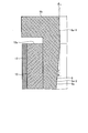
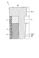
- FIG. 1 is a longitudinal sectional view showing a configuration of a rotating electrical machine according to Embodiment 1.
- FIG. FIG. 3 is a longitudinal sectional view showing the configuration of the rotor of the rotating electrical machine according to the first embodiment.
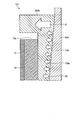
- Cross section showing the configuration of the rotor of the rotating electrical machine according to the first embodiment Partial enlarged view of FIG.
- the flowchart which shows the manufacturing method of the rotary electric machine which concerns on Embodiment 1.
- FIG. The figure which shows the stress generation state at the time of shaft press-fitting in the rotor which concerns on a comparative example
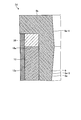
- FIG. 1 A longitudinal sectional view showing the configuration of the rotor of the rotating electrical machine according to the second embodiment
- the longitudinal cross-section which expanded a part of structure of the rotor member which concerns on the modification of Embodiment 3 The longitudinal section which expanded a part of composition of the rotor member concerning Embodiment 4
- a longitudinal sectional view showing a configuration of a rotor of a rotating electrical machine according to a fifth embodiment The longitudinal cross-sectional view which expanded a part of structure of the rotor of the rotary electric machine which concerns on Embodiment 6
- FIG. 1 is a longitudinal sectional view showing the configuration of the rotating electrical machine according to the present embodiment
- FIG. 2 is a longitudinal sectional view showing the configuration of the rotor of the rotating electrical machine according to the present embodiment
- FIG. 4 is a partially enlarged view of FIG. 2.
- FIGS. 1 and 2 are cross-sectional views of a cross section including the rotation axis A.
- FIG. 2 is a cross-sectional view taken along line II-II in FIG. 3
- FIG. 3 is a cross-sectional view taken along line III-III in FIG.
- the rotating electrical machine 1 includes an annular stator 2, a rotor 3 disposed inside the stator 2, and a shaft 4 that is a rotor shaft fixed to the rotor 3.
- the rotor 3 is a rotor of the rotating electrical machine according to the present embodiment.
- the rotor 3 is a surface permanent magnet (SPM) type as will be described below.
- the rotating electrical machine 1 is an electric motor.
- the stator 2 includes an annular stator core 5 and a coil 6 wound around the stator core 5.
- the stator core 5 is formed by laminating a plurality of electromagnetic steel plates.
- a power lead 7 is connected to the coil 6, and the power lead 7 is connected to a power source (not shown).
- the rotor 3 is disposed so as to be rotatable inside the stator 2 through the gap 8.
- the rotor 3 includes a cylindrical sleeve member 9 that is a rotor member, a plurality of permanent magnets 10 arranged on the outer peripheral surface of the sleeve member 9 so as to be spaced apart from each other in the circumferential direction, and permanent permanent adjacent to the circumferential direction.
- a plurality of gap members 11 arranged in a gap between the magnets 10, and a plurality of permanent magnets 10 and a reinforcing member 12 covering the plurality of gap members 11 in the circumferential direction are provided.
- the “circumferential direction” is the circumferential direction of the sleeve member 9.
- the “radial direction” is the radial direction of the sleeve member 9
- the “axial direction” is the axial direction of the sleeve member 9.
- the “axial direction” is equal to the rotation axis A direction.
- the sleeve member 9 is formed with a through hole 15 in the axial direction. That is, the sleeve member 9 has an inner peripheral surface 9a that forms a through hole 15 through which the shaft 4 having an angle parallel or tapered in the axial direction passes.
- the sleeve member 9 is formed of a metal magnetic material, and is formed of a steel pipe in the present embodiment.
- the shaft 4 is press-fitted into the through hole 15. At this time, press fitting may be combined with shrink fitting or cold fitting.
- the shaft 4 passes through the through hole 15, and the sleeve member 9 is fixed to the shaft 4.
- the shape and dimensions of the inner peripheral surface 9a are determined in consideration of the tightening allowance.
- the shaft 4 is formed from a steel material.
- a hollow hole 16 is formed in the shaft 4.
- the shaft 4 may be solid. Moreover, in FIG. 1, only a part of the shaft 4 is illustrated.
- the sleeve member 9 has end portions 9b and 9c that are separated from each other in the axial direction.
- the end 9b is a first end, and the end 9c is a second end.
- the end portion 9b has a flange shape. That is, the end portion 9b forms a flange portion.
- the outer peripheral surface of the sleeve member 9 excluding the end portion 9b is a cylindrical surface having the same outer diameter, and the outer diameter of this cylindrical surface is smaller than the outer diameter of the end portion 9b.
- the end portion 9b is thicker than the other portions of the sleeve member 9.
- the thickness of the sleeve member 9 excluding the end portion 9b is preferably thinner in order to facilitate the press-fitting operation of the shaft 4.
- the thickness of the sleeve member 9 excluding the end portion 9b is in the range of 1 mm to 10 mm regardless of the position in the axial direction.
- the end portion 9b is formed in a flange shape in order to suppress buckling deformation of the sleeve member 9 itself when the shaft 4 is press-fitted.
- the “thickness” is a thickness in the radial direction.
- the inner peripheral surface 9a has a tapered surface 9a-1 that is a first tapered surface whose inner diameter continuously decreases from the end 9b to the end 9c, and an inner diameter that continues from the end 9c to the end 9b. And a tapered surface 9a-2 which is a second tapered surface which is reduced in size. That is, the tapered surface 9a-1 continuously narrows radially inward from the end 9b toward the end 9c, and the tapered surface 9a-2 continuously decreases from the end 9c to the end 9b. It narrows toward the inside in the radial direction.
- the tapered surface 9a-1 is connected to the tapered surface 9a-2.
- the tapered surface 9a-1 is formed with a certain length in the axial direction from the end surface on the end 9b side of the sleeve member 9. Further, the tapered surface 9a-2 is formed with a certain length in the axial direction from the end surface on the end portion 9c side of the sleeve member 9.
- the tapered surface 9 a-1 includes the inner peripheral surface of the end portion 9 b that is a flange portion, and extends to the inner peripheral surface of the thin portion of the sleeve member 9. However, the taper surface 9a-1 does not reach the end portion 9c side beyond the position of the end surface 10a of the permanent magnet 10 in the axial direction. That is, the tapered surface 9 a-1 extends from the inner peripheral surface of the end portion 9 b to the inner peripheral surface of the thin portion of the sleeve member 9, but does not exceed the position of the end surface 10 a of the permanent magnet 10.
- the end surface 10 a is an end surface on the end 9 b side of the permanent magnet 10
- the end surface 10 b is an end surface on the end 9 c side of the permanent magnet 10.
- the tapered surface 9a-1 is a linear tapered surface having a constant inclination angle with respect to the axial direction.
- the taper surface 9a-2 is a linear taper surface having a constant inclination angle with respect to the axial direction.
- the magnitude of the inclination angle of the tapered surface 9a-2 in theta shows the magnitude of the inclination angle of the tapered surface 9a-1 in theta 2.
- the magnitudes of the inclination angles ⁇ 1 and ⁇ 2 are preferably set within a range of 0 ° to 10 ° in consideration of assembling workability, although depending on the maximum rotation speed and the tightening allowance.
- the plurality of permanent magnets 10 are arranged on the outer peripheral surface of the sleeve member 9 at equal intervals in the circumferential direction.
- the plurality of permanent magnets 10 are fixed to the outer peripheral surface of the sleeve member 9 by being attached with an adhesive.
- the plurality of gap members 11 are arranged at equal intervals in the circumferential direction on the outer peripheral surface of the sleeve member 9.
- the plurality of gap members 11 are fixed to the outer peripheral surface of the sleeve member 9 by being adhered with an adhesive.
- the gap between the permanent magnets 10 is filled with the gap member 11.
- the number of permanent magnets 10 and the number of gap members 11 are each four.
- the cross-sectional shape of the permanent magnet 10 is an arc with a constant radial thickness.
- the longitudinal sectional shape of the permanent magnet 10 is a rectangular shape.
- the axial length of the permanent magnet 10 is shorter than the axial length of the sleeve member 9.
- the permanent magnet 10 is disposed on the outer peripheral surface of the sleeve member 9 excluding the end portions 9b and 9c.
- the cross-sectional shape of the gap member 11 is an arc shape with a constant radial thickness. However, the circumferential length of the gap member 11 is shorter than the circumferential length of the permanent magnet 10.
- the vertical cross-sectional shape of the gap member 11 is a rectangular shape. The length of the gap member 11 in the axial direction is equal to the length of the permanent magnet 10 in the axial direction.
- the permanent magnet 10 is a rare earth magnet or a ferrite magnet.
- the gap member 11 is made of a nonmagnetic material. Specifically, the gap member 11 is made of stainless steel, aluminum alloy, copper alloy, iron alloy, or resin.
- the reinforcing member 12 covers the outer peripheral surfaces of the plurality of permanent magnets 10 and the plurality of gap members 11.
- the reinforcing member 12 has a cylindrical shape and is arranged coaxially with the sleeve member 9.
- the axial length of the reinforcing member 12 is equal to the axial length of the permanent magnet 10.
- the reinforcing member 12 suppresses peeling of the plurality of permanent magnets 10 and the plurality of gap members 11 from the sleeve member 9 due to centrifugal force during rotation.
- the reinforcing member 12 is made of a nonmagnetic material. Moreover, since the reinforcement member 12 aims at reinforcement, a material with high tensile strength per unit weight is used. Specifically, the reinforcing member 12 is made of carbon fiber reinforced plastic (CFRP: Carbon Fiber Reinforced Plastics), glass fiber reinforced plastic (GFRP: Glass Fiber Reinforced Plastics), synthetic fiber, titanium, or stainless steel. When the reinforcing member 12 is formed of CFRP or GFRP, the reinforcing member 12 is formed by directly winding fiber bundles or tape-like fibers around the outer peripheral surfaces of the plurality of permanent magnets 10 and the plurality of gap members 11. .
- CFRP Carbon Fiber Reinforced Plastics
- GFRP Glass Fiber Reinforced Plastics
- synthetic fiber titanium, or stainless steel.
- the rotating electrical machine 1 is disposed in the housing 20, and the stator 2 is fixed to the housing 20.
- the stator 2 is fixed to the inner peripheral surface of the housing 20 by shrink fitting, cold fitting or press fitting.
- FIG. 5 is a flowchart showing a method for manufacturing the rotating electrical machine according to the present embodiment.
- a sleeve member 9 is created.
- the sleeve member 9 is formed by cutting the outer peripheral surface and the inner peripheral surface of the steel pipe.
- a plurality of permanent magnets 10 and a plurality of gap members 11 are attached to the outer peripheral surface of the sleeve member 9.
- the gap member 11 is arranged so as to fill a gap between the permanent magnets 10 adjacent in the circumferential direction.
- the outer peripheral surfaces of the plurality of permanent magnets 10 and the plurality of gap members 11 are covered with the reinforcing member 12.
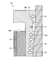
- FIG. 6 is a diagram illustrating a stress generation state at the time of shaft press-fitting in the rotor according to the comparative example.
- FIG. 6 is a partially enlarged view similar to FIG.
- the same components as those shown in FIG. 4 are denoted by the same reference numerals.
- a rotor 101 which is a rotor according to a comparative example has a sleeve member 109.
- the difference between the sleeve member 109 and the sleeve member 9 shown in FIG. 4 is that the shape of the inner peripheral surface 109a of the sleeve member 109 is different from the shape of the inner peripheral surface 9a shown in FIG.
- the inner peripheral surface 109a is a single linear taper surface with a constant inclination angle with respect to the axial direction, and the inner peripheral surface 109a extends from the flange-shaped end 109b of the sleeve member 109 to the sleeve member 109. As it goes to the end (not shown), it expands continuously and uniformly outward in the radial direction.
- the other configuration of the rotor 101 is the same as that of the rotor 3 shown in FIG.
- FIG. 6 shows stresses 30 and 31 acting on the inner peripheral surface 109a of the sleeve member 109 when the shaft 104 is press-fitted.
- the shaft 104 is press-fitted into the sleeve member 109 from the end side (not shown) of the sleeve member 109.
- the inner peripheral surface 109a is formed of a single linear tapered surface, and the inner diameter of the inner peripheral surface 109a is continuously and uniformly narrowed from the end (not shown) of the sleeve member 109 toward the end 109b.
- the stress 31 acting on the highly rigid end portion 109b is larger than the stress 30 acting on the thin portion of the sleeve member 109 where the thickness variation is small.
- the stress 31 acting on the end 109b reduces the workability of the shaft press-fitting work.
- FIG. 7 is a diagram showing a state of stress generation when the shaft is press-fitted in the rotor according to the present embodiment. 7 is a partially enlarged view similar to FIG. 4. In FIG. 7, the same components as those shown in FIG. 4 are denoted by the same reference numerals.
- the inner peripheral surface 9a is composed of tapered surfaces 9a-1 and 9a-2 having different inclination directions.
- the taper surface 9a-1 expands radially outward from the boundary with the taper surface 9a-2 toward the end 9b so as to reduce the interference between the sleeve member 9 and the shaft 4. .
- the stress 32 acting on the end portion 9b is reduced more than the stress 31 in the comparative example, and can be made equal to the stress 32 acting on the thin portion of the sleeve member 9. That is, in the present embodiment, the stress 32 acting on the end portion 9b having a large thickness and high rigidity can be reduced, and the shaft press-fitting operation becomes easy.
- the end portion 9b does not need to hold the permanent magnet 10, and the taper surface 9a-1 reduces the tightening margin, thereby reducing the surface pressure acting on the end portion 9b.
- the taper surface 9a-1 reduces the tightening margin, thereby reducing the surface pressure acting on the end portion 9b.
- the thin portion of the sleeve member 9 excluding the end portion 9c needs to hold the permanent magnet 10, a tightening margin is secured by the tapered surface 9a-2.
- buckling of the sleeve member 9 can be suppressed by press-fitting the shaft 4 into the sleeve member 9 while supporting the end portion 9b which is a flange portion.
- the quality of the rotor 3 improves.
- the inner peripheral surface 9a includes the tapered surface 9a-1, the pressure input of the shaft 4 is reduced, and workability at the time of manufacturing the rotor 3 can be improved.
- the tapered surface 9a-2 is a linear tapered surface, but the present invention is not limited to this. The same applies to the tapered surface 9a-1.
- the tapered surfaces 9a-1 and 9a-2 may be non-linear tapered surfaces whose inclination angle with respect to the axial direction changes.
- the taper surface 9a-2 is made of a single linear taper surface, the present invention is not limited to this, and a plurality of linear taper surfaces having different inclination angles with respect to the axial direction may be connected to each other.
- the magnitude of the inclination angle of the plurality of linear tapered surfaces can be set so as to decrease in order from the end portion 9c toward the end portion 9b.
- the tapered surface 9a-1 may be configured by connecting a plurality of linear tapered surfaces having different inclination angles with respect to the axial direction.
- the magnitudes of the inclination angles of the plurality of linear tapered surfaces can be set so as to decrease sequentially from the end portion 9b toward the end portion 9c.
- the thickness of the sleeve member 9 excluding the end portion 9b that is, the thickness of the thin portion of the sleeve member 9 is in the range of 1 mm to 10 mm, but depending on the material of the sleeve member 9 The thickness may be outside the range.
- the number of permanent magnets 10 is four, but the number of permanent magnets 10 is not limited to this.
- the number of permanent magnets 10 is determined according to the number of poles of the rotor 3. Further, the permanent magnet 10 may be divided in the axial direction.
- the gap member 11 is the same as the permanent magnet 10.
- the gap member 11 is formed of a nonmagnetic material. By forming the gap member 11 from a nonmagnetic material, the magnetic flux short-circuit loss inside the sleeve member 9 and the gap member 11 is suppressed.
- the gap member 11 may be formed of a material other than a nonmagnetic material.
- the material of the gap member 11 can be selected so that the specific gravity is equal to the specific gravity of the permanent magnet 10. Therefore, since the centrifugal force acting on the gap member 11 and the permanent magnet 10 is equalized, local stress concentration on the reinforcing member 12 is suppressed.
- the gap member 11 is arranged for the purpose of improving the workability of attaching the permanent magnet 10 and equalizing the stress to the reinforcing member 12, and can be omitted. In particular, there is no problem if the stress applied to the reinforcing member 12 is less than the fatigue strength of the reinforcing member 12. Further, the gap member 11 can be omitted by arranging the plurality of permanent magnets 10 in the circumferential direction without any gap.
- the reinforcing member 12 is made of a nonmagnetic material. Thereby, the output fall of the rotary electric machine 1 by a leakage magnetic flux can be suppressed.
- the reinforcing member 12 is made of carbon fiber reinforced plastic, glass fiber reinforced plastic, synthetic fiber, titanium, or stainless steel, but may be formed by combining a plurality of materials selected from these materials. .
- a space is provided between the end 9b and the permanent magnet 10. Thereby, the magnetic flux leakage from the edge part of the permanent magnet 10 is suppressed.
- the structure which lengthens the length of the axial direction of the permanent magnet 10 and makes the end surface 10a contact the edge part 9b is also possible. However, in this case, magnetic flux leakage from the permanent magnet 10 through the end 9b may occur.
- FIG. FIG. 8 is a longitudinal sectional view showing the configuration of the rotor of the rotating electrical machine according to the present embodiment.
- the same components as those of the rotor 3 shown in FIG. 8 the same components as those of the rotor 3 shown in FIG.
- the rotor 3a includes a cylindrical sleeve member 35 that is a rotor member.
- the sleeve member 35 has an inner peripheral surface 35 a that forms the through hole 15.
- the sleeve member 35 has end portions 35b and 35c that are spaced apart from each other in the axial direction.
- the end portion 35b is a first end portion
- the end portion 35c is a second end portion.
- both the end portions 35b and 35c have a flange shape. That is, the end portion 35b forms a first flange portion, and the end portion 35c forms a second flange portion.
- the outer peripheral surface of the sleeve member 35 excluding the end portions 35b and 35c is a cylindrical surface having the same outer diameter, and the outer diameter of the cylindrical surface is smaller than the outer diameter of the end portions 35b and 35c.
- the end portions 35 b and 35 c are thicker than the other portions of the sleeve member 35.
- the thickness of the sleeve member 35 excluding the end portions 35b and 35c, that is, the thickness of the thin portion of the sleeve member 35 is in the range of 1 mm to 10 mm regardless of the position in the axial direction.
- the inner peripheral surface 35a has a tapered surface 35a-1 that is a first tapered surface whose inner diameter continuously decreases from the end 35b toward the end 35c, and an inner diameter that continues from the end 35c toward the end 35b.
- Taper surfaces 35a-2 and 35a-3 which are second taper surfaces that are reduced in size. That is, the second taper surface is configured by connecting the taper surfaces 35a-2 and 35a-3 to each other.
- the tapered surface 35a-1 is connected to the tapered surface 35a-3.
- the tapered surface 35a-1 is formed with a certain length in the axial direction from the end surface of the sleeve member 35 on the end portion 35b side. Further, the tapered surface 35a-2 is formed with a certain length in the axial direction from the end surface of the sleeve member 35 on the end portion 35c side.
- the tapered surface 35a-1 is a linear tapered surface having a constant inclination angle with respect to the axial direction.
- the tapered surface 35 a-1 includes the inner peripheral surface of the end portion 35 b that is the first flange portion, and extends to the inner peripheral surface of the thin portion of the sleeve member 35.
- the taper surface 35a-1 does not extend to the end portion 35c side beyond the position of the end surface 10a of the permanent magnet 10 in the axial direction. That is, the tapered surface 35 a-1 extends from the inner peripheral surface of the end portion 35 b to the inner peripheral surface of the thin portion of the sleeve member 35, but does not exceed the position of the end surface 10 a of the permanent magnet 10.
- the tapered surface 35a-2 is a linear tapered surface having a constant inclination angle with respect to the axial direction.
- the tapered surface 35 a-2 includes the inner peripheral surface of the end portion 35 c that is the second flange portion, and extends to the inner peripheral surface of the thin portion of the sleeve member 35.
- the taper surface 35a-2 does not extend to the end portion 35b side beyond the position of the end surface 10b of the permanent magnet 10 in the axial direction. That is, the tapered surface 35 a-2 extends from the inner peripheral surface of the end portion 35 c to the inner peripheral surface of the thin portion of the sleeve member 35, but does not exceed the position of the end surface 10 b of the permanent magnet 10.
- the tapered surface 35a-3 is a linear tapered surface having a constant inclination angle with respect to the axial direction. However, the inclination angle of the tapered surface 35a-3 is different from the inclination angle of the tapered surface 35a-2. Specifically, the inclination angle of the tapered surface 35a-2 is larger than the inclination angle of the tapered surface 35a-3.
- the tapered surface 35a-3 is disposed between the tapered surfaces 35a-1 and 35a-2.
- the inclination angle of the tapered surfaces 35a-1, 35a-2, 35a-3 is set within a range of 0 ° to 10 °.
- the other structure of the rotor 3a is the same as that of the rotor 3 shown in FIG.
- a shaft (not shown) is press-fitted into the sleeve member 35 from the end 35c side.
- the taper surface 35a-1 extends from the boundary with the taper surface 35a-3 so as to reduce the interference between the sleeve member 35 and the shaft (not shown). As it goes to the part 35b, it expands radially outward. Therefore, the stress acting on the end portion 35b can be reduced similarly to the stress acting on the thin portion of the sleeve member 35.
- buckling of the sleeve member 35 can be suppressed by press-fitting a shaft (not shown) into the sleeve member 35 while supporting both ends 35b and 35c, which are flange portions.
- the inclination angle of the tapered surface 35a-2 is made larger than the inclination angle of the tapered surface 35a-3.
- the first tapered surface whose inner diameter continuously decreases from the end portion 35b toward the end portion 35c is the tapered surface 35a-1 that is a single linear tapered surface.
- the second tapered surfaces whose inner diameter continuously decreases from the end portion 35c toward the end portion 35b are tapered surfaces 35a-2 and 35a-3 which are two linear tapered surfaces connected to each other.
- the second tapered surface can be a single linear tapered surface as in the first embodiment.
- the second tapered surface can be configured by connecting three or more linear tapered surfaces having different inclination angles with respect to the axial direction.
- the magnitudes of the inclination angles of these three or more linear tapered surfaces can be set so as to decrease sequentially from the end portion 35c toward the end portion 35b.
- the range of the three or more linear tapered surfaces closest to the end portion 35c may be limited so as not to extend beyond the end portion 10b of the permanent magnet 10 in the axial direction. it can.
- the first tapered surface can be configured by connecting a plurality of linear tapered surfaces having different inclination angles with respect to the axial direction.
- the magnitude of the inclination angle of the plurality of linear taper surfaces can be set so as to decrease sequentially from the end portion 35b toward the end portion 35c.
- FIG. 9 is a longitudinal sectional view showing the configuration of the rotor of the rotating electrical machine according to the present embodiment.
- the same components as those of the rotor 3 shown in FIG. 9 are identical components as those of the rotor 3 shown in FIG.
- the rotor 3b includes a cylindrical sleeve member 36 that is a rotor member.
- the sleeve member 36 has an inner peripheral surface 36 a that forms the through hole 15.
- the sleeve member 36 has end portions 36b and 36c that are spaced apart from each other in the axial direction.
- the end portion 36b is a first end portion, and the end portion 36c is a second end portion.
- the end portion 36b has a flange shape. That is, the end portion 36b forms a flange portion.
- the outer peripheral surface of the sleeve member 36 excluding the end portion 36b is a cylindrical surface having the same outer diameter, and the outer diameter of the cylindrical surface is smaller than the outer diameter of the end portion 36b.
- the end 36b is thicker than the other part of the sleeve member 36.
- the thickness of the sleeve member 36 excluding the end portion 36b, that is, the thickness of the thin portion of the sleeve member 36 is in the range of 1 mm to 10 mm regardless of the position in the axial direction.
- the inner peripheral surface 36a has an inner diameter that gradually decreases from the end 36c toward the end 36b. That is, the inner peripheral surface 36a is continuously reduced in inner diameter from the end portion 36c toward the end portion 36b except for the groove portion 37. Since the groove part 37 is formed in the inner peripheral surface 36a, the inner peripheral surface 36a is gradually narrowed inward in the radial direction from the end part 36c toward the end part 36b.
- annular groove portion 37 is formed on the inner peripheral surface 36a adjacent to the end portion 36b in the circumferential direction.
- the groove part 37 is the same depth over the circumferential direction.
- the cross-sectional shape of the groove part 37 is a rectangle.
- the groove portion 37 does not reach the end portion 36c side beyond the position of the end surface 10a of the permanent magnet 10 in the axial direction. That is, the groove portion 37 is disposed adjacent to the end portion 36b in the axial direction, but is in a range not exceeding the position of the end surface 10a of the permanent magnet 10.
- the inner peripheral surface 36 a is a linear tapered surface having a constant inclination angle with respect to the axial direction except for the groove portion 37.
- the magnitude of the inclination angle is set within a range of 0 ° to 10 °. That is, the inner peripheral surface 36 a can be regarded as a linear tapered surface having a constant inclination angle with respect to the axial direction interrupted by the groove portion 37.
- FIG. 10 is a diagram showing a state of stress generation when the shaft is press-fitted in the rotor according to the present embodiment.
- FIG. 10 is a partially enlarged view similar to FIG. 7.
- the same components as those shown in FIG. 7 are denoted by the same reference numerals.
- FIG. 10 shows stresses 40 and 41 acting on the inner peripheral surface 36a of the sleeve member 36 when the shaft 4b is press-fitted.
- the shaft 4b is press-fitted into the sleeve member 36 from the end 36c side shown in FIG.
- the groove portion 37 is provided adjacent to the end portion 36b which is the flange portion, the thickness of the sleeve member 36 becomes thinner at the groove portion 37, and the stress acting on the end portion 36b from the shaft 4b. 40 is relaxed. Therefore, the stress 40 acting on the end portion 36 b can be made equal to the stress 40 acting on the thin portion of the sleeve member 36 excluding the groove portion 37.
- the groove portion 37 is provided in the sleeve member 36 between the end portion 36b and the permanent magnet 10 in the axial direction, thereby reducing the stress 40 acting on the end portion 36b.
- the stress 41 acting on the groove portion 37 can be made smaller than the stress 40 acting on other portions of the sleeve member 36.
- the other structure of the rotor 3b is the same as that of the rotor 3 shown in FIG.
- FIG. 11 is a diagram showing the relationship between the surface pressure generated in the sleeve member and the axial distance.
- the surface pressure corresponds to the stresses 40 and 41 described above.
- FIG 11 shows the rotor 3b according to the present embodiment and a part of the longitudinal sectional configuration of the rotor 101 according to the comparative example shown in FIG.
- the rotor 3b is obtained by providing a groove 37 on the rotor 101, and the rotor 3b is shown by showing the groove 37 with a dotted line on the rotor 101.
- the lower part of FIG. 11 shows a curve L1 indicating the relationship between the axial distance of the sleeve member 36 and the surface pressure generated on the inner peripheral surface 36a, and the axial distance of the sleeve member 109 and the inner peripheral surface 109a.
- the curve L2 which shows the relationship with a surface pressure is shown.
- the unit of axial distance is mm, and the unit of surface pressure is MPa.
- the groove portion 37 by providing the groove portion 37, the surface pressure generated at the end portion 36b that is the flange portion can be reduced as compared with the comparative example.
- buckling of the sleeve member 36 can be suppressed by press-fitting the shaft 4b into the sleeve member 36 with the end portion 36b which is a flange portion as a support.
- the quality of the rotor 3b improves.
- the groove portion 37 is provided adjacent to the end portion 36b on the inner peripheral surface 36a, the pressure input of the shaft 4b is reduced, and the workability when the rotor 3b is manufactured. Can be improved.
- the cross-sectional shape of the groove portion 37 is rectangular, but the present invention is not limited to this. If an example is given, the cross-sectional shape of the groove part 37 can also be made into semicircle shape. Further, other configurations, operations, and effects of the present embodiment are the same as those of the first embodiment.
- FIG. 12 is an enlarged longitudinal sectional view showing a part of the configuration of the rotor member according to the modification of the present embodiment.
- the same components as those shown in FIG. 10 are denoted by the same reference numerals.
- the sleeve member 36 which is a rotor member according to this modification, has an inner peripheral surface 36a whose inner diameter is intermittently reduced from the end portion 36c toward the end portion 36b, as in the present embodiment.
- the inner peripheral surface 36a of the present modification is composed of two tapered surfaces 36a-1 and 36a-2 having different inclination angles with respect to the axial direction with the groove 37 interposed therebetween.
- the tapered surfaces 36a-1 and 36a-2 are linear tapered surfaces, respectively.
- the magnitude of the inclination angle with respect to the axial direction is indicated by ⁇ 1 for the tapered surface 36a-2, and the magnitude of the inclination angle with respect to the axial direction is indicated by ⁇ 3 for the tapered surface 36a-1.
- the inclination angle magnitude ⁇ 3 is smaller than the inclination angle magnitude ⁇ 1 .
- the inclination angle of the magnitude theta 3 because smaller than the size theta 1 of the inclination angle, interference is reduced at the ends 36b, stress acting on the end portion 36b is more relaxed.
- Other configurations, operations, and effects of the present modification are the same as those of the present embodiment.
- the inclination angle magnitude ⁇ 3 is smaller than the inclination angle magnitude ⁇ 1 , the inclination angle magnitude ⁇ 3 can be made larger than the inclination angle magnitude ⁇ 1 .
- FIG. 13 is an enlarged longitudinal section of a part of the configuration of the rotor member according to the present embodiment.
- the same components as those shown in FIG. 9 are denoted by the same reference numerals.
- the sleeve member 39 which is a rotor member according to the present embodiment, has the same shape as the sleeve member 36 shown in FIG. 9 except for the shape of the inner peripheral surface 39a. That is, the sleeve member 39 has an end portion 39b which is a flange portion and an end portion which is not shown in FIG.
- the end not shown in FIG. 13 is an end corresponding to the end 36c shown in FIG.
- the end 39b is a first end, and an end not shown in FIG. 13 is a second end.
- a groove portion 37 is provided on the inner peripheral surface 39a of the sleeve member 39 adjacent to the end portion 39b.
- the inner peripheral surface 39a is composed of two tapered surfaces 39a-1 and 39a-2 with the groove portion 37 interposed therebetween. That is, the tapered surface 39a-1 is connected to the tapered surface 39a-2 via the groove portion 37.
- the taper surface 39a-1 is a linear taper surface whose inner diameter continuously decreases from the end portion 39b toward the end portion (not shown).
- the taper surface 39a-2 is a linear taper surface whose inner diameter is continuously reduced from the end (not shown) toward the end 39b.
- the magnitude of the inclination angle with respect to the axial direction is represented by ⁇ 1
- the magnitude of the inclination angle with respect to the axial direction is represented by ⁇ 4 .
- the inclination angle magnitude ⁇ 4 is smaller than the inclination angle magnitude ⁇ 1 , but the inclination angle magnitude ⁇ 4 may be greater than or equal to the inclination angle magnitude ⁇ 1 .
- the sleeve member 39 according to the present embodiment can be regarded as the groove member 37 provided in the sleeve member 9 according to the first embodiment shown in FIG. Therefore, the present embodiment also has the same effect as the first embodiment.
- FIG. 14 is a longitudinal sectional view showing the configuration of the rotor of the rotating electrical machine according to the present embodiment.
- the same components as those of the rotor 3b shown in FIG. 14 are identical components as those of the rotor 3b shown in FIG.
- the rotor 3c includes a cylindrical sleeve member 45 that is a rotor member.
- the sleeve member 45 has an inner peripheral surface 45 a that forms the through hole 15.
- the sleeve member 45 has end portions 45b and 45c that are spaced apart from each other in the axial direction.
- the end 45b is a first end
- the end 45c is a second end.
- both the end portions 45b and 45c have a flange shape. That is, the end portion 45b forms a first flange portion, and the end portion 45c forms a second flange portion.
- the outer peripheral surface of the sleeve member 45 excluding the end portions 45b and 45c is a cylindrical surface having the same outer diameter, and the outer diameter of the cylindrical surface is smaller than the outer diameter of the end portions 45b and 45c.
- the end portions 45 b and 45 c are thicker than the other portions of the sleeve member 45.
- the thickness of the sleeve member 45 excluding the end portions 45b and 45c, that is, the thickness of the thin portion of the sleeve member 45 is in the range of 1 mm to 10 mm regardless of the position in the axial direction.
- the inner peripheral surface 45a has an inner diameter that decreases intermittently from the end 45c toward the end 45b. That is, since the grooves 46a and 46b are formed on the inner peripheral surface 45a, the inner peripheral surface 45a is intermittently narrowed radially inward from the end 45c toward the end 45b.
- annular groove 46a is formed on the inner peripheral surface 45a in the circumferential direction adjacent to the end 45b, and an annular groove 46b is formed in the circumferential direction adjacent to the end 45c. .
- the groove portions 46a and 46b have the same depth over the circumferential direction.
- the cross-sectional shapes of the grooves 46a and 46b are each rectangular.
- the groove 46a does not reach the end 45c side beyond the position of the end face 10a of the permanent magnet 10 in the axial direction. That is, the groove 46a is disposed adjacent to the end 45b in the axial direction, but is in a range not exceeding the position of the end face 10a of the permanent magnet 10.
- the groove 46b does not reach the end 45b side beyond the position of the end face 10b of the permanent magnet 10 in the axial direction. That is, the groove 46b is disposed adjacent to the end 45c in the axial direction, but is in a range not exceeding the position of the end face 10b of the permanent magnet 10.
- the inner peripheral surface 45a is a linear tapered surface having a constant inclination angle with respect to the axial direction, except for the grooves 46a and 46b.
- the magnitude of the inclination angle is set within a range of 0 ° to 10 °. That is, the inner peripheral surface 45a can be regarded as a linear taper surface having a constant inclination angle with respect to the axial direction interrupted by the grooves 46a and 46b.
- the groove portion 46b is provided on the inner peripheral surface 45a adjacent to the end portion 45c, the stress acting on the end portion 45c when the shaft is press-fitted can be reduced.
- buckling of the sleeve member 45 can be suppressed by press-fitting a shaft (not shown) into the sleeve member 45 with both ends 45b and 45c, which are flange portions, as a support.
- the cross-sectional shape of the grooves 46a and 46b is rectangular, but the present invention is not limited to this.
- the cross-sectional shape of the groove portions 46a and 46b may be a semicircular shape.
- Other configurations, operations, and effects of the present embodiment are the same as those of the third embodiment.
- FIG. 15 is an enlarged longitudinal sectional view of a part of the configuration of the rotor of the rotating electrical machine according to the present embodiment.
- the same components as those shown in FIG. 2 are denoted by the same reference numerals.
- a spacer 50 is provided between the flange-shaped end portion 9 b and the permanent magnet 10.
- the spacer 50 is sandwiched between the end 9 b and the permanent magnet 10.
- the spacer 50 is disposed on the outer peripheral surface of the sleeve member 9.
- the spacer 50 is formed of a nonmagnetic material. Specifically, the spacer 50 is formed of stainless steel, aluminum alloy, copper alloy, iron alloy, or resin.
- the spacer 50 is annular, and the inner peripheral surface and the outer peripheral surface of the spacer 50 each form a cylindrical surface.
- the outer diameter of the spacer 50 is equal to the outer diameter of a cylindrical outer peripheral surface constituted by a plurality of permanent magnets 10 and a plurality of gap members not shown in FIG. As described in Embodiment 1, a configuration in which a plurality of gap members are not provided is also possible.
- the outer peripheral surface of the end portion 9 b is a cylindrical surface, and the outer diameter of the end portion 9 b is larger than the outer diameter of the spacer 50.
- the axial length of the reinforcing member 12 a is longer than the axial length of the permanent magnet 10 and shorter than the axial length of the sleeve member 9.
- the reinforcing member 12 a also covers the outer peripheral surface of the spacer 50.
- magnetic flux leakage from the end of the permanent magnet 10 can be suppressed by forming the spacer 50 with a nonmagnetic material.
- FIG. 16 is an enlarged longitudinal sectional view of a part of the configuration of the rotor of the rotating electrical machine according to the present embodiment.
- the same components as those shown in FIGS. 9 and 12 are denoted by the same reference numerals.
- a spacer 51 is provided between the flange-shaped end portion 36b and the permanent magnet 10.
- the spacer 51 is sandwiched between the end portion 36 b and the permanent magnet 10.
- the spacer 51 is disposed on the outer peripheral surface of the sleeve member 36.
- the spacer 51 is formed of a nonmagnetic material. Specifically, the spacer 51 is formed of stainless steel, aluminum alloy, copper alloy, iron alloy, or resin.
- the spacer 51 is annular, and the inner peripheral surface and outer peripheral surface of the spacer 51 each form a cylindrical surface.
- the outer diameter of the spacer 51 is equal to the outer diameter of a cylindrical outer peripheral surface constituted by a plurality of permanent magnets 10 and a plurality of gap members not shown in FIG. As described in the sixth embodiment, a configuration in which a plurality of gap members are not provided is also possible.
- the outer peripheral surface of the end portion 36 b is a cylindrical surface, and the outer diameter of the end portion 36 b is larger than the outer diameter of the spacer 51.
- the axial length of the reinforcing member 12a is longer than the axial length of the permanent magnet 10 and shorter than the axial length of the sleeve member 36.
- the reinforcing member 12 a also covers the outer peripheral surface of the spacer 51.
- magnetic flux leakage from the end of the permanent magnet 10 can be suppressed by forming the spacer 51 with a nonmagnetic material.
- the configuration described in the above embodiment shows an example of the contents of the present invention, and can be combined with another known technique, and can be combined with other configurations without departing from the gist of the present invention. It is also possible to omit or change the part.
Landscapes
- Engineering & Computer Science (AREA)
- Power Engineering (AREA)
- Permanent Field Magnets Of Synchronous Machinery (AREA)
- Iron Core Of Rotating Electric Machines (AREA)
Abstract
Priority Applications (7)
| Application Number | Priority Date | Filing Date | Title |
|---|---|---|---|
| CN201680002240.2A CN107231822B (zh) | 2016-01-26 | 2016-01-26 | 旋转电机的转子部件、旋转电机的转子及旋转电机 |
| KR1020177003509A KR101919718B1 (ko) | 2016-01-26 | 2016-01-26 | 회전 전기의 회전자 부재, 회전 전기의 회전자 및 회전 전기 |
| PCT/JP2016/052187 WO2017130295A1 (fr) | 2016-01-26 | 2016-01-26 | Rotor pour machine électrique rotative, machine électrique rotative et élément de rotor pour machine électrique rotative |
| US15/502,908 US10651698B2 (en) | 2016-01-26 | 2016-01-26 | Rotor of rotary electric machine, rotary electric machine, and rotor member of rotary electric machine |
| DE112017000001.7T DE112017000001T5 (de) | 2016-01-26 | 2016-01-26 | Rotor einer elektrischen Rotationsmaschine, elektrische Rotationsmaschine und Rotorelement einer elektrischen Rotationsmaschine |
| JP2016559385A JP6072395B1 (ja) | 2016-01-26 | 2016-01-26 | 回転電機の回転子部材、回転電機の回転子及び回転電機 |
| TW105104602A TWI574488B (zh) | 2016-01-26 | 2016-02-17 | 旋轉電機之轉子、旋轉電機及旋轉電機之轉子構件 |
Applications Claiming Priority (1)
| Application Number | Priority Date | Filing Date | Title |
|---|---|---|---|
| PCT/JP2016/052187 WO2017130295A1 (fr) | 2016-01-26 | 2016-01-26 | Rotor pour machine électrique rotative, machine électrique rotative et élément de rotor pour machine électrique rotative |
Publications (1)
| Publication Number | Publication Date |
|---|---|
| WO2017130295A1 true WO2017130295A1 (fr) | 2017-08-03 |
Family
ID=57937612
Family Applications (1)
| Application Number | Title | Priority Date | Filing Date |
|---|---|---|---|
| PCT/JP2016/052187 WO2017130295A1 (fr) | 2016-01-26 | 2016-01-26 | Rotor pour machine électrique rotative, machine électrique rotative et élément de rotor pour machine électrique rotative |
Country Status (7)
| Country | Link |
|---|---|
| US (1) | US10651698B2 (fr) |
| JP (1) | JP6072395B1 (fr) |
| KR (1) | KR101919718B1 (fr) |
| CN (1) | CN107231822B (fr) |
| DE (1) | DE112017000001T5 (fr) |
| TW (1) | TWI574488B (fr) |
| WO (1) | WO2017130295A1 (fr) |
Cited By (5)
| Publication number | Priority date | Publication date | Assignee | Title |
|---|---|---|---|---|
| JP6505345B1 (ja) * | 2018-01-31 | 2019-04-24 | 三菱電機株式会社 | 回転子部材、回転子及び回転電機 |
| WO2019150499A1 (fr) * | 2018-01-31 | 2019-08-08 | 三菱電機株式会社 | Élément de rotor, rotor et dispositif électrique tournant |
| EP3430705A4 (fr) * | 2016-03-15 | 2019-11-13 | General Atomics | Ensemble rotor et procédé de fabrication |
| WO2020194382A1 (fr) * | 2019-03-22 | 2020-10-01 | 三菱電機株式会社 | Élément de rotor, rotor et machine électrique tournante |
| US20220224192A1 (en) * | 2019-05-02 | 2022-07-14 | Festool Gmbh | Drive motor with an insulating housing |
Families Citing this family (7)
| Publication number | Priority date | Publication date | Assignee | Title |
|---|---|---|---|---|
| JP6351915B1 (ja) * | 2017-05-25 | 2018-07-04 | 三菱電機株式会社 | 回転子部材及び回転電機 |
| WO2018216161A1 (fr) * | 2017-05-25 | 2018-11-29 | 三菱電機株式会社 | Rotor, et machine électrique tournante |
| KR102218809B1 (ko) * | 2017-05-29 | 2021-02-22 | 미쓰비시덴키 가부시키가이샤 | 회전자, 회전 전기 및 회전자의 제조 방법 |
| GB2563617B (en) * | 2017-06-20 | 2020-04-08 | Dyson Technology Ltd | An electric machine |
| WO2021259412A1 (fr) * | 2020-06-22 | 2021-12-30 | Schaeffler Technologies AG & Co. KG | Rotor et machine à flux radial |
| CN117321884A (zh) * | 2021-05-18 | 2023-12-29 | 松下知识产权经营株式会社 | 转子及电动机 |
| FR3134931A1 (fr) * | 2022-04-22 | 2023-10-27 | Erneo | Piece rotative du type « rotor » a aimants en surface et machine electrique et/ou magnetique associee. |
Citations (2)
| Publication number | Priority date | Publication date | Assignee | Title |
|---|---|---|---|---|
| JP2000245086A (ja) * | 1999-02-18 | 2000-09-08 | Shinko Electric Co Ltd | 永久磁石型回転電機のロータ |
| JP2003111327A (ja) * | 2001-09-28 | 2003-04-11 | Nissan Motor Co Ltd | モータの回転子構造および回転子固定方法ならびに鉄心保持具 |
Family Cites Families (17)
| Publication number | Priority date | Publication date | Assignee | Title |
|---|---|---|---|---|
| DE2048643B1 (de) | 1970-10-03 | 1972-01-05 | Peter O | Spannsatz mit konischen, verzahnten Ringen zur Nabenbefestigung |
| DE7433645U (de) | 1973-10-10 | 1975-01-16 | Aktieselskabet Thomas Ths Sabroe & | Spannbuchse zur Befestigung von Riemenscheiben und dgl. an Wellen |
| SU1208351A1 (ru) | 1983-09-30 | 1986-01-30 | Предприятие П/Я А-1944 | Соединение валов |
| US5779449A (en) * | 1996-04-15 | 1998-07-14 | Ansimag Inc. | Separable, multipartite impeller assembly for centrifugal pumps |
| JPH1080080A (ja) * | 1996-09-02 | 1998-03-24 | Osada Res Inst Ltd | ブラシレスモータ |
| JP3484051B2 (ja) | 1997-09-10 | 2004-01-06 | 株式会社 日立インダストリイズ | 永久磁石式同期電動機及びその製造方法ならびに永久磁石式同期電動機を備えた遠心圧縮機 |
| US6238202B1 (en) * | 1999-02-26 | 2001-05-29 | Unique Mould Makers Limited | Apparatus for ejecting threaded injection molded parts |
| JP4377325B2 (ja) | 2002-07-10 | 2009-12-02 | 株式会社日立製作所 | 永久磁石式回転電機、空気圧縮機及びタービン発電機 |
| JP4359814B2 (ja) | 2002-12-24 | 2009-11-11 | ミネベア株式会社 | ロータ構造 |
| KR101096469B1 (ko) * | 2003-07-10 | 2011-12-20 | 마그네틱 애플리케이션 인크. | 소형 고전력 교류 발전기 |
| TWM307244U (en) * | 2006-05-12 | 2007-03-01 | Jen-Shing Huang | Rotor of motor |
| JP2009148864A (ja) | 2007-12-21 | 2009-07-09 | Kuroda Precision Ind Ltd | 工具ホルダ |
| DE102008006489A1 (de) | 2008-01-29 | 2009-07-30 | Dr. Ing. H.C. F. Porsche Aktiengesellschaft | Spannelement |
| TWM348419U (en) * | 2008-07-29 | 2009-01-01 | Lnc Technology Co Ltd | Rotor structure with variable inertia |
| JP5689550B2 (ja) | 2013-04-03 | 2015-03-25 | ファナック株式会社 | 回転電機の回転軸部に固定される回転子部材、回転子部材を備える回転子、および回転電機、ならびに、回転子を製造する方法 |
| JP5820046B2 (ja) | 2013-12-27 | 2015-11-24 | ファナック株式会社 | 磁石保持構造を備えた電動機の回転子及びそれを備える電動機 |
| CN203962184U (zh) * | 2014-07-01 | 2014-11-26 | 舟山和成机械有限公司 | 一种高强度耐磨发动机活塞组件 |
-
2016
- 2016-01-26 WO PCT/JP2016/052187 patent/WO2017130295A1/fr active Application Filing
- 2016-01-26 KR KR1020177003509A patent/KR101919718B1/ko active IP Right Grant
- 2016-01-26 JP JP2016559385A patent/JP6072395B1/ja active Active
- 2016-01-26 CN CN201680002240.2A patent/CN107231822B/zh active Active
- 2016-01-26 US US15/502,908 patent/US10651698B2/en active Active
- 2016-01-26 DE DE112017000001.7T patent/DE112017000001T5/de active Pending
- 2016-02-17 TW TW105104602A patent/TWI574488B/zh active
Patent Citations (2)
| Publication number | Priority date | Publication date | Assignee | Title |
|---|---|---|---|---|
| JP2000245086A (ja) * | 1999-02-18 | 2000-09-08 | Shinko Electric Co Ltd | 永久磁石型回転電機のロータ |
| JP2003111327A (ja) * | 2001-09-28 | 2003-04-11 | Nissan Motor Co Ltd | モータの回転子構造および回転子固定方法ならびに鉄心保持具 |
Cited By (6)
| Publication number | Priority date | Publication date | Assignee | Title |
|---|---|---|---|---|
| EP3430705A4 (fr) * | 2016-03-15 | 2019-11-13 | General Atomics | Ensemble rotor et procédé de fabrication |
| JP6505345B1 (ja) * | 2018-01-31 | 2019-04-24 | 三菱電機株式会社 | 回転子部材、回転子及び回転電機 |
| WO2019150500A1 (fr) * | 2018-01-31 | 2019-08-08 | 三菱電機株式会社 | Élément de rotor, rotor et dispositif électrique rotatif |
| WO2019150499A1 (fr) * | 2018-01-31 | 2019-08-08 | 三菱電機株式会社 | Élément de rotor, rotor et dispositif électrique tournant |
| WO2020194382A1 (fr) * | 2019-03-22 | 2020-10-01 | 三菱電機株式会社 | Élément de rotor, rotor et machine électrique tournante |
| US20220224192A1 (en) * | 2019-05-02 | 2022-07-14 | Festool Gmbh | Drive motor with an insulating housing |
Also Published As
| Publication number | Publication date |
|---|---|
| KR20180100075A (ko) | 2018-09-07 |
| CN107231822B (zh) | 2020-02-07 |
| US20180054100A1 (en) | 2018-02-22 |
| DE112017000001T5 (de) | 2018-03-01 |
| JPWO2017130295A1 (ja) | 2018-02-01 |
| JP6072395B1 (ja) | 2017-02-01 |
| TWI574488B (zh) | 2017-03-11 |
| TW201728055A (zh) | 2017-08-01 |
| CN107231822A (zh) | 2017-10-03 |
| KR101919718B1 (ko) | 2018-11-16 |
| US10651698B2 (en) | 2020-05-12 |
Similar Documents
| Publication | Publication Date | Title |
|---|---|---|
| JP6072395B1 (ja) | 回転電機の回転子部材、回転電機の回転子及び回転電機 | |
| US10128727B2 (en) | Rotor member, rotor, electric motor, machine tool, and manufacturing method of rotor | |
| JP7337973B2 (ja) | 同期リラクタンス機械及び、同期リラクタンス機械を製造する方法 | |
| JP5820046B2 (ja) | 磁石保持構造を備えた電動機の回転子及びそれを備える電動機 | |
| JP5964394B2 (ja) | 電動機の回転子、電動機、工作機械、および回転子の製造方法 | |
| CN107528396B (zh) | 转子构件、转子以及电动机 | |
| WO2010001776A1 (fr) | Structure de rotor de machine rotative du type à aimant permanent | |
| WO2016143008A1 (fr) | Rotor d'une machine électrique rotative, et procédé de fabrication de rotor d'une machine électrique rotative | |
| JP2009148158A (ja) | シェル形磁石を備える永久励磁型の同期機 | |
| CN107579614B (zh) | 电机转子及高速永磁电机 | |
| US10707711B2 (en) | Rotor and rotating electrical machine | |
| JP5386885B2 (ja) | 永久磁石式回転機の回転子構造 | |
| JP6616388B2 (ja) | 回転子及び回転電機 | |
| US20150233421A1 (en) | Magnetic radial bearing with a rotor laminated in a star-shaped manner | |
| JP6505345B1 (ja) | 回転子部材、回転子及び回転電機 | |
| JP6370521B1 (ja) | 回転子及び回転電機 | |
| JP2009239988A (ja) | 永久磁石式モータ | |
| JP4323941B2 (ja) | 励磁機、界磁機およびそれを用いた同期機 | |
| WO2019150499A1 (fr) | Élément de rotor, rotor et dispositif électrique tournant | |
| US11742711B1 (en) | Rotor for a high speed electrical machine | |
| US20220263363A1 (en) | Rotating electric machine rotor | |
| JP2009072036A (ja) | 永久磁石式回転機の回転子構造 | |
| RU2574606C1 (ru) | Ротор электромашины | |
| JP2017169373A (ja) | 回転子部材及び回転電機 | |
| WO2020194382A1 (fr) | Élément de rotor, rotor et machine électrique tournante |
Legal Events
| Date | Code | Title | Description |
|---|---|---|---|
| ENP | Entry into the national phase |
Ref document number: 2016559385 Country of ref document: JP Kind code of ref document: A |
|
| ENP | Entry into the national phase |
Ref document number: 20177003509 Country of ref document: KR Kind code of ref document: A |
|
| WWE | Wipo information: entry into national phase |
Ref document number: 112017000001 Country of ref document: DE |
|
| WWE | Wipo information: entry into national phase |
Ref document number: 15502908 Country of ref document: US |
|
| 121 | Ep: the epo has been informed by wipo that ep was designated in this application |
Ref document number: 16887882 Country of ref document: EP Kind code of ref document: A1 |
|
| 122 | Ep: pct application non-entry in european phase |
Ref document number: 16887882 Country of ref document: EP Kind code of ref document: A1 |