WO2017126338A1 - エンコーダ装置、駆動装置、ステージ装置、及びロボット装置 - Google Patents
エンコーダ装置、駆動装置、ステージ装置、及びロボット装置 Download PDFInfo
- Publication number
- WO2017126338A1 WO2017126338A1 PCT/JP2017/000284 JP2017000284W WO2017126338A1 WO 2017126338 A1 WO2017126338 A1 WO 2017126338A1 JP 2017000284 W JP2017000284 W JP 2017000284W WO 2017126338 A1 WO2017126338 A1 WO 2017126338A1
- Authority
- WO
- WIPO (PCT)
- Prior art keywords
- unit
- battery
- power
- electric signal
- rotation
- Prior art date
Links
- 238000001514 detection method Methods 0.000 claims abstract description 185
- 230000007274 generation of a signal involved in cell-cell signaling Effects 0.000 claims abstract description 118
- 230000008859 change Effects 0.000 claims description 12
- 238000010248 power generation Methods 0.000 description 19
- 238000010586 diagram Methods 0.000 description 14
- 230000002093 peripheral effect Effects 0.000 description 14
- 238000012423 maintenance Methods 0.000 description 11
- 230000003287 optical effect Effects 0.000 description 10
- 238000012545 processing Methods 0.000 description 9
- 238000004891 communication Methods 0.000 description 7
- 239000003990 capacitor Substances 0.000 description 6
- 230000005540 biological transmission Effects 0.000 description 5
- 230000004048 modification Effects 0.000 description 4
- 238000012986 modification Methods 0.000 description 4
- 230000015572 biosynthetic process Effects 0.000 description 3
- 239000003638 chemical reducing agent Substances 0.000 description 3
- 230000009467 reduction Effects 0.000 description 3
- 238000003786 synthesis reaction Methods 0.000 description 3
- 238000002834 transmittance Methods 0.000 description 3
- 230000003111 delayed effect Effects 0.000 description 2
- 230000005674 electromagnetic induction Effects 0.000 description 2
- 238000000034 method Methods 0.000 description 2
- 238000000059 patterning Methods 0.000 description 2
- 230000008569 process Effects 0.000 description 2
- 230000002194 synthesizing effect Effects 0.000 description 2
- 230000001133 acceleration Effects 0.000 description 1
- 230000000694 effects Effects 0.000 description 1
- 238000009499 grossing Methods 0.000 description 1
- 230000012447 hatching Effects 0.000 description 1
- 230000001939 inductive effect Effects 0.000 description 1
- 238000009413 insulation Methods 0.000 description 1
- 230000031700 light absorption Effects 0.000 description 1
- 230000005389 magnetism Effects 0.000 description 1
- 230000007246 mechanism Effects 0.000 description 1
- 230000010349 pulsation Effects 0.000 description 1
- 230000004044 response Effects 0.000 description 1
- 230000000717 retained effect Effects 0.000 description 1
- 238000007493 shaping process Methods 0.000 description 1
Images


Classifications
-
- G—PHYSICS
- G01—MEASURING; TESTING
- G01D—MEASURING NOT SPECIALLY ADAPTED FOR A SPECIFIC VARIABLE; ARRANGEMENTS FOR MEASURING TWO OR MORE VARIABLES NOT COVERED IN A SINGLE OTHER SUBCLASS; TARIFF METERING APPARATUS; MEASURING OR TESTING NOT OTHERWISE PROVIDED FOR
- G01D5/00—Mechanical means for transferring the output of a sensing member; Means for converting the output of a sensing member to another variable where the form or nature of the sensing member does not constrain the means for converting; Transducers not specially adapted for a specific variable
- G01D5/26—Mechanical means for transferring the output of a sensing member; Means for converting the output of a sensing member to another variable where the form or nature of the sensing member does not constrain the means for converting; Transducers not specially adapted for a specific variable characterised by optical transfer means, i.e. using infrared, visible, or ultraviolet light
- G01D5/32—Mechanical means for transferring the output of a sensing member; Means for converting the output of a sensing member to another variable where the form or nature of the sensing member does not constrain the means for converting; Transducers not specially adapted for a specific variable characterised by optical transfer means, i.e. using infrared, visible, or ultraviolet light with attenuation or whole or partial obturation of beams of light
- G01D5/34—Mechanical means for transferring the output of a sensing member; Means for converting the output of a sensing member to another variable where the form or nature of the sensing member does not constrain the means for converting; Transducers not specially adapted for a specific variable characterised by optical transfer means, i.e. using infrared, visible, or ultraviolet light with attenuation or whole or partial obturation of beams of light the beams of light being detected by photocells
- G01D5/347—Mechanical means for transferring the output of a sensing member; Means for converting the output of a sensing member to another variable where the form or nature of the sensing member does not constrain the means for converting; Transducers not specially adapted for a specific variable characterised by optical transfer means, i.e. using infrared, visible, or ultraviolet light with attenuation or whole or partial obturation of beams of light the beams of light being detected by photocells using displacement encoding scales
- G01D5/3473—Circular or rotary encoders
-
- G—PHYSICS
- G01—MEASURING; TESTING
- G01D—MEASURING NOT SPECIALLY ADAPTED FOR A SPECIFIC VARIABLE; ARRANGEMENTS FOR MEASURING TWO OR MORE VARIABLES NOT COVERED IN A SINGLE OTHER SUBCLASS; TARIFF METERING APPARATUS; MEASURING OR TESTING NOT OTHERWISE PROVIDED FOR
- G01D5/00—Mechanical means for transferring the output of a sensing member; Means for converting the output of a sensing member to another variable where the form or nature of the sensing member does not constrain the means for converting; Transducers not specially adapted for a specific variable
- G01D5/12—Mechanical means for transferring the output of a sensing member; Means for converting the output of a sensing member to another variable where the form or nature of the sensing member does not constrain the means for converting; Transducers not specially adapted for a specific variable using electric or magnetic means
- G01D5/14—Mechanical means for transferring the output of a sensing member; Means for converting the output of a sensing member to another variable where the form or nature of the sensing member does not constrain the means for converting; Transducers not specially adapted for a specific variable using electric or magnetic means influencing the magnitude of a current or voltage
- G01D5/20—Mechanical means for transferring the output of a sensing member; Means for converting the output of a sensing member to another variable where the form or nature of the sensing member does not constrain the means for converting; Transducers not specially adapted for a specific variable using electric or magnetic means influencing the magnitude of a current or voltage by varying inductance, e.g. by a movable armature
- G01D5/22—Mechanical means for transferring the output of a sensing member; Means for converting the output of a sensing member to another variable where the form or nature of the sensing member does not constrain the means for converting; Transducers not specially adapted for a specific variable using electric or magnetic means influencing the magnitude of a current or voltage by varying inductance, e.g. by a movable armature differentially influencing two coils
- G01D5/2291—Linear or rotary variable differential transformers (LVDTs/RVDTs) having a single primary coil and two secondary coils
-
- B—PERFORMING OPERATIONS; TRANSPORTING
- B25—HAND TOOLS; PORTABLE POWER-DRIVEN TOOLS; MANIPULATORS
- B25J—MANIPULATORS; CHAMBERS PROVIDED WITH MANIPULATION DEVICES
- B25J19/00—Accessories fitted to manipulators, e.g. for monitoring, for viewing; Safety devices combined with or specially adapted for use in connection with manipulators
- B25J19/02—Sensing devices
-
- G—PHYSICS
- G01—MEASURING; TESTING
- G01D—MEASURING NOT SPECIALLY ADAPTED FOR A SPECIFIC VARIABLE; ARRANGEMENTS FOR MEASURING TWO OR MORE VARIABLES NOT COVERED IN A SINGLE OTHER SUBCLASS; TARIFF METERING APPARATUS; MEASURING OR TESTING NOT OTHERWISE PROVIDED FOR
- G01D5/00—Mechanical means for transferring the output of a sensing member; Means for converting the output of a sensing member to another variable where the form or nature of the sensing member does not constrain the means for converting; Transducers not specially adapted for a specific variable
- G01D5/12—Mechanical means for transferring the output of a sensing member; Means for converting the output of a sensing member to another variable where the form or nature of the sensing member does not constrain the means for converting; Transducers not specially adapted for a specific variable using electric or magnetic means
- G01D5/244—Mechanical means for transferring the output of a sensing member; Means for converting the output of a sensing member to another variable where the form or nature of the sensing member does not constrain the means for converting; Transducers not specially adapted for a specific variable using electric or magnetic means influencing characteristics of pulses or pulse trains; generating pulses or pulse trains
- G01D5/24428—Error prevention
- G01D5/24447—Error prevention by energy backup
-
- G—PHYSICS
- G01—MEASURING; TESTING
- G01D—MEASURING NOT SPECIALLY ADAPTED FOR A SPECIFIC VARIABLE; ARRANGEMENTS FOR MEASURING TWO OR MORE VARIABLES NOT COVERED IN A SINGLE OTHER SUBCLASS; TARIFF METERING APPARATUS; MEASURING OR TESTING NOT OTHERWISE PROVIDED FOR
- G01D5/00—Mechanical means for transferring the output of a sensing member; Means for converting the output of a sensing member to another variable where the form or nature of the sensing member does not constrain the means for converting; Transducers not specially adapted for a specific variable
- G01D5/26—Mechanical means for transferring the output of a sensing member; Means for converting the output of a sensing member to another variable where the form or nature of the sensing member does not constrain the means for converting; Transducers not specially adapted for a specific variable characterised by optical transfer means, i.e. using infrared, visible, or ultraviolet light
- G01D5/32—Mechanical means for transferring the output of a sensing member; Means for converting the output of a sensing member to another variable where the form or nature of the sensing member does not constrain the means for converting; Transducers not specially adapted for a specific variable characterised by optical transfer means, i.e. using infrared, visible, or ultraviolet light with attenuation or whole or partial obturation of beams of light
- G01D5/34—Mechanical means for transferring the output of a sensing member; Means for converting the output of a sensing member to another variable where the form or nature of the sensing member does not constrain the means for converting; Transducers not specially adapted for a specific variable characterised by optical transfer means, i.e. using infrared, visible, or ultraviolet light with attenuation or whole or partial obturation of beams of light the beams of light being detected by photocells
- G01D5/347—Mechanical means for transferring the output of a sensing member; Means for converting the output of a sensing member to another variable where the form or nature of the sensing member does not constrain the means for converting; Transducers not specially adapted for a specific variable characterised by optical transfer means, i.e. using infrared, visible, or ultraviolet light with attenuation or whole or partial obturation of beams of light the beams of light being detected by photocells using displacement encoding scales
- G01D5/34707—Scales; Discs, e.g. fixation, fabrication, compensation
- G01D5/34715—Scale reading or illumination devices
-
- G—PHYSICS
- G01—MEASURING; TESTING
- G01D—MEASURING NOT SPECIALLY ADAPTED FOR A SPECIFIC VARIABLE; ARRANGEMENTS FOR MEASURING TWO OR MORE VARIABLES NOT COVERED IN A SINGLE OTHER SUBCLASS; TARIFF METERING APPARATUS; MEASURING OR TESTING NOT OTHERWISE PROVIDED FOR
- G01D2205/00—Indexing scheme relating to details of means for transferring or converting the output of a sensing member
- G01D2205/20—Detecting rotary movement
- G01D2205/26—Details of encoders or position sensors specially adapted to detect rotation beyond a full turn of 360°, e.g. multi-rotation
-
- G—PHYSICS
- G01—MEASURING; TESTING
- G01D—MEASURING NOT SPECIALLY ADAPTED FOR A SPECIFIC VARIABLE; ARRANGEMENTS FOR MEASURING TWO OR MORE VARIABLES NOT COVERED IN A SINGLE OTHER SUBCLASS; TARIFF METERING APPARATUS; MEASURING OR TESTING NOT OTHERWISE PROVIDED FOR
- G01D5/00—Mechanical means for transferring the output of a sensing member; Means for converting the output of a sensing member to another variable where the form or nature of the sensing member does not constrain the means for converting; Transducers not specially adapted for a specific variable
- G01D5/12—Mechanical means for transferring the output of a sensing member; Means for converting the output of a sensing member to another variable where the form or nature of the sensing member does not constrain the means for converting; Transducers not specially adapted for a specific variable using electric or magnetic means
- G01D5/14—Mechanical means for transferring the output of a sensing member; Means for converting the output of a sensing member to another variable where the form or nature of the sensing member does not constrain the means for converting; Transducers not specially adapted for a specific variable using electric or magnetic means influencing the magnitude of a current or voltage
- G01D5/142—Mechanical means for transferring the output of a sensing member; Means for converting the output of a sensing member to another variable where the form or nature of the sensing member does not constrain the means for converting; Transducers not specially adapted for a specific variable using electric or magnetic means influencing the magnitude of a current or voltage using Hall-effect devices
- G01D5/145—Mechanical means for transferring the output of a sensing member; Means for converting the output of a sensing member to another variable where the form or nature of the sensing member does not constrain the means for converting; Transducers not specially adapted for a specific variable using electric or magnetic means influencing the magnitude of a current or voltage using Hall-effect devices influenced by the relative movement between the Hall device and magnetic fields
-
- G—PHYSICS
- G01—MEASURING; TESTING
- G01D—MEASURING NOT SPECIALLY ADAPTED FOR A SPECIFIC VARIABLE; ARRANGEMENTS FOR MEASURING TWO OR MORE VARIABLES NOT COVERED IN A SINGLE OTHER SUBCLASS; TARIFF METERING APPARATUS; MEASURING OR TESTING NOT OTHERWISE PROVIDED FOR
- G01D5/00—Mechanical means for transferring the output of a sensing member; Means for converting the output of a sensing member to another variable where the form or nature of the sensing member does not constrain the means for converting; Transducers not specially adapted for a specific variable
- G01D5/54—Mechanical means for transferring the output of a sensing member; Means for converting the output of a sensing member to another variable where the form or nature of the sensing member does not constrain the means for converting; Transducers not specially adapted for a specific variable using means specified in two or more of groups G01D5/02, G01D5/12, G01D5/26, G01D5/42, and G01D5/48
- G01D5/56—Mechanical means for transferring the output of a sensing member; Means for converting the output of a sensing member to another variable where the form or nature of the sensing member does not constrain the means for converting; Transducers not specially adapted for a specific variable using means specified in two or more of groups G01D5/02, G01D5/12, G01D5/26, G01D5/42, and G01D5/48 using electric or magnetic means
-
- G—PHYSICS
- G01—MEASURING; TESTING
- G01D—MEASURING NOT SPECIALLY ADAPTED FOR A SPECIFIC VARIABLE; ARRANGEMENTS FOR MEASURING TWO OR MORE VARIABLES NOT COVERED IN A SINGLE OTHER SUBCLASS; TARIFF METERING APPARATUS; MEASURING OR TESTING NOT OTHERWISE PROVIDED FOR
- G01D5/00—Mechanical means for transferring the output of a sensing member; Means for converting the output of a sensing member to another variable where the form or nature of the sensing member does not constrain the means for converting; Transducers not specially adapted for a specific variable
- G01D5/54—Mechanical means for transferring the output of a sensing member; Means for converting the output of a sensing member to another variable where the form or nature of the sensing member does not constrain the means for converting; Transducers not specially adapted for a specific variable using means specified in two or more of groups G01D5/02, G01D5/12, G01D5/26, G01D5/42, and G01D5/48
- G01D5/58—Mechanical means for transferring the output of a sensing member; Means for converting the output of a sensing member to another variable where the form or nature of the sensing member does not constrain the means for converting; Transducers not specially adapted for a specific variable using means specified in two or more of groups G01D5/02, G01D5/12, G01D5/26, G01D5/42, and G01D5/48 using optical means, i.e. using infrared, visible or ultraviolet light
Definitions
- the present invention relates to an encoder device, a driving device, a stage device, and a robot device.
- a multi-rotation type encoder device that distinguishes the number of rotations of a shaft is mounted on various devices such as a robot device (for example, see Patent Document 1 below).
- the encoder apparatus receives power supply from, for example, a main power supply of the robot apparatus, and includes rotational position information including multi-rotation information indicating the number of rotations and angular position information indicating an angular position of less than one rotation. Is detected.
- the robot apparatus finishes the predetermined processing, its main power may be turned off. In this case, the power supply from the main power supply of the robot apparatus to the encoder apparatus is also stopped.
- the robot apparatus may require information such as an initial posture when the main power source is turned on next time, that is, when the next operation is started. For this reason, the encoder device is required to retain the multi-rotation information even in a state where power is not supplied from the outside. Therefore, an encoder device that retains multi-rotation information with power supplied from a battery in a state where power supply from the main power source cannot be obtained is used.
- the encoder apparatus as described above has no battery maintenance (eg, replacement) or the maintenance frequency is low.
- a position detection system including a detection unit that detects position information of the moving unit, an electric signal generating unit that generates an electric signal by the movement of the moving unit, and an electric signal generating unit
- an encoder device including a battery that supplies at least a part of power consumed by the position detection system in accordance with an electrical signal to be transmitted.
- the apparatus includes a position detection unit that detects position information of the moving unit by supplying power, and a signal generation unit that outputs a signal by moving the moving unit, and is based on the output signal.
- a position detection unit that detects position information of the moving unit by supplying power
- a signal generation unit that outputs a signal by moving the moving unit, and is based on the output signal.
- an encoder device is provided in which power is supplied to the position detector.
- a drive device including the encoder device according to the first aspect or the second aspect, and a power supply unit that supplies power to the moving unit.
- a stage device including a moving object and a driving device according to the third aspect for moving the moving object.
- a robot apparatus including the driving device according to the third aspect, and a first arm and a second arm that are relatively moved by the driving device.
- FIG. 1 is a diagram showing an encoder device EC according to the present embodiment.
- the encoder device EC detects rotational position information of the rotation shaft SF (moving unit) of the motor M (power supply unit).
- the rotating shaft SF is, for example, a shaft (rotor) of the motor M, and is a working shaft (output shaft) connected to the shaft of the motor M via a power transmission unit such as a transmission and to a load. May be.
- the rotational position information detected by the encoder device EC is supplied to the motor control unit MC.
- the motor control unit MC controls the rotation of the motor M using the rotational position information supplied from the encoder device EC.
- the motor control unit MC controls the rotation of the rotation shaft SF.
- Encoder device EC includes a position detection system 1 and a power supply system 2.
- the position detection system 1 detects rotation position information of the rotation axis SF.
- the encoder device EC is a so-called multi-rotation absolute encoder, and detects rotational position information including multi-rotation information indicating the number of rotations of the rotating shaft SF and angular position information indicating an angular position (rotation angle) of less than one rotation.
- the encoder device EC includes a multi-rotation information detection unit 3 that detects multi-rotation information of the rotation axis SF, and an angle detection unit 4 that detects an angular position of the rotation axis SF.
- At least a part of the position detection system 1 (for example, the angle detection unit 4) is, for example, in a state where the power of a device (for example, a drive device, a stage device, a robot device) on which the encoder device EC is mounted is turned on. It operates with power supplied from this device.
- at least a part of the position detection system 1 (for example, the multi-rotation information detection unit 3) supplies power from the power supply system 2 in a state in which the power of the device on which the encoder device EC is mounted is not turned on, for example. To work.
- the power supply system 2 is intermittently connected to at least a part of the position detection system 1 (for example, the multi-rotation information detection unit 3) in a state where the power supply from the device on which the encoder device EC is mounted is cut off.
- the position detection system 1 detects at least a part (for example, multi-rotation information) of the rotational position information of the rotation axis SF when power is supplied from the power supply system 2. .
- the multi-rotation information detection unit 3 detects multi-rotation information by magnetism, for example.
- the multi-rotation information detection unit 3 includes, for example, a magnet 11, a magnetic detection unit 12, a detection unit 13, and a storage unit 14.
- the magnet 11 is provided on a disk 15 fixed to the rotation shaft SF. Since the disk 15 rotates with the rotation axis SF, the magnet 11 rotates in conjunction with the rotation axis SF.
- the magnet 11 is fixed to the outside of the rotating shaft SF, and the relative positions of the magnet 11 and the magnetic detection unit 12 change according to the rotation of the rotating shaft SF.
- the strength and direction of the magnetic field on the magnetic detection unit 12 formed by the magnet 11 changes according to the rotation of the rotation axis SF.
- the magnetic detection unit 12 detects the magnetic field formed by the magnet 11, and the detection unit 13 detects the position information of the rotation axis SF based on the result of the magnetic detection unit 12 detecting the magnetic field formed by the magnet.
- the storage unit 14 stores the position information detected by the detection unit 13.
- the angle detection unit 4 is an optical or magnetic encoder, and detects position information (angle position information) within one rotation of the scale. For example, in the case of an optical encoder, the angular position within one rotation of the rotation axis SF is detected by reading patterning information of the scale with a light receiving element, for example.
- the scale patterning information is, for example, bright and dark slits on the scale.
- the angle detection unit 4 detects angular position information of the rotation axis SF that is the same as the detection target of the multi-rotation information detection unit 3.
- the angle detection unit 4 includes a light emitting element 21, a scale S, a light receiving sensor 22, and a detection unit 23.
- the scale S is provided on a disc fixed to the rotating shaft SF.
- the scale S includes an incremental scale and an absolute scale.
- the scale S may be provided on the disk 15 or may be a member integrated with the disk 15.
- the scale S may be provided on the surface of the disc 15 opposite to the magnet 11.
- the scale S may be provided on at least one of the inside and the outside of the magnet 11.
- the light emitting element 21 irradiation unit, light emitting unit irradiates the scale S with light.
- the light receiving sensor 22 (light detection unit) detects light emitted from the light emitting element 21 and passing through the scale S.
- the angle detection unit 4 is a transmission type, and the light receiving sensor 22 detects light transmitted through the scale S.
- the angle detector 4 may be a reflection type.
- the light receiving sensor 22 supplies a signal indicating the detection result to the detection unit 23.
- the detection unit 23 detects the angular position of the rotation axis SF using the detection result of the light receiving sensor 22.
- the detection unit 23 detects the angular position of the first resolution using the result of detecting the light from the absolute scale.
- the detection unit 23 detects an angular position of the second resolution higher than the first resolution by performing an interpolation operation on the angular position of the first resolution using the result of detecting the light from the incremental scale. .
- the encoder device EC includes a signal processing unit 25.
- the signal processing unit 25 processes the detection result by the position detection system 1.
- the signal processing unit 25 includes a synthesis unit 26 and an external communication unit 27.
- the synthesizing unit 26 acquires the angular position information of the second resolution detected by the detecting unit 23. Further, the synthesis unit 26 acquires the multi-rotation information of the rotation axis SF from the storage unit 14 of the multi-rotation information detection unit 3.
- the synthesizer 26 synthesizes the angular position information from the detector 23 and the multi-rotation information from the multi-rotation information detector 3 to calculate rotational position information.
- the synthesis unit 26 calculates (2 ⁇ ⁇ n + ⁇ ) as rotation position information.
- the rotation position information may be information obtained by combining multi-rotation information and angular position information of less than one rotation.
- the synthesizing unit 26 supplies the rotational position information to the external communication unit 27.
- the external communication unit 27 is communicably connected to the communication unit MC1 of the motor control unit MC by wire or wireless.
- the external communication unit 27 supplies digital rotational position information to the communication unit MC1 of the motor control unit MC.
- the motor control unit MC appropriately decodes the rotational position information from the external communication unit 27 of the angle detection unit 4.
- the motor control unit MC controls the rotation of the motor M by controlling the power (drive power) supplied to the motor M using the rotational position information.
- the power supply system 2 includes an electric signal generation unit 31, a battery (battery) 32, and a switching unit 33.
- the electric signal generating unit 31 generates an electric signal by the rotation of the rotating shaft SF.
- This electric signal includes, for example, a waveform in which power (current, voltage) changes with time.
- electric power is generated as an electric signal by a magnetic field that changes in accordance with the rotation of the rotating shaft SF.
- electric power is generated in the electrical signal generation unit 31 by a change in the magnetic field formed by the magnet 11 used by the multi-rotation information detection unit 3 to detect the multi-rotation position of the rotation axis SF.
- the electrical signal generation unit 31 is arranged such that the relative angular position with the magnet 11 changes as the rotation axis SF rotates. For example, when the relative position between the electrical signal generation unit 31 and the magnet 11 reaches a predetermined position, the electrical signal generation unit 31 generates a pulsed electrical signal.
- the battery 32 supplies at least a part of the electric power consumed by the position detection system 1 according to the electric signal generated by the electric signal generating unit 31.
- the battery 32 is a primary battery such as a button-type battery or a dry battery.
- the battery 32 is a button-type battery, for example, and is held by the holding unit 35.
- the holding unit 35 is, for example, a circuit board on which at least a part of the position detection system 1 is provided.
- the holding unit 35 holds, for example, the detection unit 13, the switching unit 33, and the storage unit 14.
- the holding unit 35 is provided with, for example, a battery case that can accommodate the battery 32, electrodes connected to the battery 32, wiring, and the like.
- the switching unit 33 switches the presence / absence of power supply from the battery 32 to the position detection system 1 in accordance with the electrical signal generated by the electrical signal generation unit 31. For example, the switching unit 33 starts supplying power from the battery 32 to the position detection system 1 when the level of the electrical signal generated by the electrical signal generation unit 31 is equal to or higher than a threshold value. For example, the switching unit 33 starts the supply of power from the battery 32 to the position detection system 1 when the electric signal generation unit 31 generates power that is equal to or greater than the threshold value. Further, the switching unit 33 stops the supply of power from the battery 32 to the position detection system 1 when the level of the electrical signal generated by the electrical signal generation unit 31 is less than the threshold value.
- the switching unit 33 stops the supply of power from the battery 32 to the position detection system 1 when the power generated by the electrical signal generation unit 31 becomes less than the threshold value. For example, when a pulsed electric signal is generated in the electric signal generating unit 31, the switching unit 33 causes the position detection system 1 from the battery 32 when the level (electric power) of the electric signal rises from a low level to a high level. The power supply from the battery 32 to the position detection system 1 is stopped after a predetermined time has elapsed since the level (power) of the electric signal has changed to a low level.
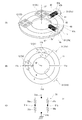
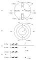
- FIG. 2 is a diagram illustrating the magnet 11, the electric signal generation unit 31, and the magnetic detection unit 12 according to the present embodiment.
- 2A shows a perspective view of the magnet 11, the electric signal generation unit 31, and the magnetic detection unit 12.
- FIG. 2B shows the magnet 11 and the electric signal generation unit 31 viewed from the direction of the rotation axis SF. And a plan view of the magnetic detection unit 12 is shown.
- FIG. 2C shows the circuit configuration of the magnetic sensor 51.
- the magnet 11 is configured to change the direction and strength of the magnetic field in the radial direction (radial direction) with respect to the rotation axis SF by rotation.
- the magnet 11 is, for example, an annular member that is coaxial with the rotation axis SF.
- the main surface (front surface and back surface) of the magnet 11 is substantially perpendicular to the rotation axis SF.
- the magnet 11 is a permanent magnet magnetized with four poles.
- the magnet 11 has N poles and S poles arranged in the circumferential direction on the inner peripheral side and the outer peripheral side thereof, and the phase is shifted by 180 ° between the inner peripheral side and the outer peripheral side.
- the boundary between the N pole and the S pole on the inner peripheral side substantially coincides with the boundary between the N pole and the S pole on the outer peripheral side in the circumferential direction (angular position).
- the counterclockwise rotation when viewed from the front end side of the rotating shaft SF (the side opposite to the motor M in FIG. 1) is referred to as forward rotation, and the clockwise rotation is referred to as reverse rotation.
- the forward rotation angle is represented by a positive value
- the reverse rotation angle is represented by a negative value. Note that, when viewed from the base end side (the motor M side in FIG. 1) of the rotation shaft SF, counterclockwise rotation may be defined as forward rotation, and clockwise rotation as reverse rotation.
- the angular position of one boundary between the N pole and the S pole in the circumferential direction is represented by a position 11a
- the angular position rotated 90 ° from the position 11a is represented by a position 11b
- An angular position rotated 90 ° from the position 11b is represented by a position 11c
- a position rotated 90 ° from the position 11c is represented by a position 11d.
- the position 11c is an angular position of another boundary between the N pole and the S pole in the circumferential direction.
- the N pole is disposed on the outer peripheral side of the magnet 11, and the S pole is disposed on the inner peripheral side of the magnet 11.
- the direction of the magnetic field in the radial direction is generally the direction from the outer peripheral side of the magnet 11 toward the inner peripheral side.
- the strength of the magnetic field is maximum at the position 11b and is minimum near the position 11a and near the position 11c.
- the N pole is disposed on the inner peripheral side of the magnet 11, and the S pole is disposed on the outer peripheral side of the magnet 11.
- the direction of the magnetic field in the radial direction is a direction from the inner peripheral side of the magnet 11 toward the outer peripheral side.
- the strength of the magnetic field is maximum at the position 11d and is minimum near the position 11a and near the position 11c.
- the radial direction of the magnetic field formed by the magnet 11 is reversed at the position 11a and reversed at the position 11c.
- the magnet 11 forms an alternating magnetic field in which the direction of the radial magnetic field is reversed with the rotation of the magnet 11 with respect to the coordinate system fixed outside the magnet 11.
- the electric signal generation unit 31 is disposed at a position overlapping the magnet 11 when viewed from the normal direction of the main surface of the magnet 11.
- a first electric signal generation unit 31a and a second electric signal generation unit 31b are provided as the electric signal generation unit 31 .
- the first electric signal generation unit 31a and the second electric signal generation unit 31b are provided in non-contact with the magnet 11, respectively.
- the first electric signal generation unit 31 a includes a first magnetic sensing unit 41 and a first power generation unit 42.
- the first magnetic sensing unit 41 and the first power generation unit 42 are fixed to the outside of the magnet 11, and relative positions with respect to the respective positions on the magnet 11 change as the magnet 11 rotates.
- the position 11b of the magnet 11 is disposed at a position of 45 ° counterclockwise from the first electric signal generating unit 31a, and the magnet 11 is moved forward (counterclockwise) from this state. ),
- the position 11b, the position 11c, the position 11d, and the position 11a pass through the vicinity of the electric signal generating unit 31 in this order.
- the first magnetic sensitive part 41 is a magnetic sensitive wire such as a Wiegand wire.
- a large Barkhausen jump (Wiegand effect) occurs in the first magnetic sensing part 41 due to a change in the magnetic field accompanying the rotation of the magnet 11.
- the first magnetic sensitive part 41 is a cylindrical member, and the axial direction thereof is set to the radial direction of the magnet 11. In the first magnetic sensing part 41, when an AC magnetic field is applied in the axial direction and the magnetic field is reversed, a domain wall is generated from one end to the other end in the axial direction.
- the first power generation unit 42 is a high-density coil or the like that is wound around the first magnetic sensing unit 41.
- electromagnetic induction occurs due to the occurrence of the domain wall in the first magnetic sensing unit 41, and an induced current flows.
- a pulsed current (electric signal) is generated in the first power generation unit 42.
- the direction of the current generated in the first power generation unit 42 changes according to the direction before and after the reversal of the magnetic field.
- the direction of the current generated when reversing from the magnetic field facing the outside of the magnet 11 to the magnetic field facing the inside is opposite to the direction of the current generated when reversing from the magnetic field facing the inside of the magnet 11 to the magnetic field facing the outside.
- the power (inductive current) generated in the first power generation unit 42 can be set by, for example, the number of turns of the high-density coil.
- the first magnetic sensing part 41 and the first power generation part 42 are housed in a case 43.
- the case 43 is provided with a terminal 43a and a terminal 43b.
- One end of the high-density coil of the first power generation unit 42 is electrically connected to the terminal 43a, and the other end is electrically connected to the terminal 43b.
- the electric power generated in the first power generation unit 42 can be taken out of the first electric signal generation unit 31a via the terminal 43a and the terminal 43b.
- the second electric signal generating unit 31b is arranged at an angular position that forms an angle larger than 0 ° and smaller than 180 ° from the angular position where the first electric signal generating unit 31a is arranged.
- the angle between the angular position of the first electrical signal generating unit 31a and the angular position of the second electrical signal generating unit 31b is selected from a range of 45 ° to 135 °, and is approximately 90 ° in FIG. 2B.
- the second electric signal generation unit 31 b has the same configuration as the first electric signal generation unit 31.
- the second electric signal generation unit 31 b includes a second magnetic sensitive unit 45 and a second power generation unit 46.
- the second magnetic sensing unit 45 and the second power generation unit 46 are the same as the first magnetic sensing unit 41 and the first power generation unit 42, respectively, and description thereof is omitted.
- the second magnetic sensing unit 45 and the second power generation unit 46 are housed in a case 47.
- the case 47 is provided with a terminal 47a and a terminal 47b.
- the electric power generated in the second power generation unit 46 can be taken out of the second electric signal generation unit 31a via the terminal 47a and the terminal 47b.
- the magnetic detection unit 12 includes a magnetic sensor 51 and a magnetic sensor 52.
- the magnetic sensor 51 is arranged at an angular position greater than 0 ° and less than 90 ° with respect to the first magnetic sensitive part 41 (first electric signal generation unit 31a) in the rotation direction of the rotation axis SF.
- the magnetic sensor 52 is arranged at an angular position greater than 90 ° and less than 180 ° with respect to the first magnetic sensing part 41 (first electric signal generation unit 31a) in the rotation direction of the rotation axis SF.
- the magnetic sensor 51 includes a magnetoresistive element 56, a bias magnet (not shown) that applies a magnetic field having a certain strength to the magnetoresistive element 56, and a waveform from the magnetoresistive element 56.
- a waveform shaping circuit (not shown).
- the magnetoresistive element 56 has a full bridge shape in which the element 56a, the element 56b, the element 56c, and the element 56d are connected in series.
- a signal line between the element 56a and the element 56c is connected to the power supply terminal 51p.
- a signal line between the element 56b and the element 56d is connected to the ground terminal 51g.
- a signal line between the element 56a and the element 56b is connected to the first output terminal 51a.
- a signal line between the element 56c and the element 56d is connected to the second output terminal 51b.
- the magnetic sensor 52 has the same configuration as the magnetic sensor 51, and a description thereof is omitted.
- FIG. 3 is a diagram illustrating a circuit configuration of the power supply system 2 and the multi-rotation information detection unit 3 according to the present embodiment.
- the power supply system 2 includes a first electric signal generation unit 31a, a rectification stack 61, a second electric signal generation unit 31b, a rectification stack 62, and a battery 32.
- the power supply system 2 includes a regulator 63 as the switching unit 33 shown in FIG.
- the rectification stack 61 is a rectifier that rectifies the current flowing from the first electric signal generation unit 31a.
- the first input terminal 61a of the rectifying stack 61 is connected to the terminal 43a of the first electric signal generating unit 31a.
- the second input terminal 61b of the rectifying stack 61 is connected to the terminal 43b of the first electric signal generating unit 31a.
- the ground terminal 61g of the rectifying stack 61 is connected to a ground line GL to which the same potential as the signal ground SG is supplied. During the operation of the multi-rotation information detection unit 3, the potential of the ground line GL becomes the reference potential of the circuit.
- the output terminal 61 c of the rectifying stack 61 is connected to the control terminal 63 a of the regulator 63.
- the rectification stack 62 is a rectifier that rectifies the current flowing from the second electric signal generation unit 31b.
- the first input terminal 62a of the rectifying stack 62 is connected to the terminal 47a of the second electric signal generating unit 31b.
- the second input terminal 62b of the rectification stack 62 is connected to the terminal 47b of the second electric signal generation unit 31b.
- the ground terminal 62g of the rectifying stack 62 is connected to the ground line GL.
- the output terminal 62 c of the rectifying stack 62 is connected to the control terminal 63 a of the regulator 63.
- the regulator 63 adjusts the electric power supplied from the battery 32 to the position detection system 1.
- the regulator 63 may include a switch 64 provided in a power supply path between the battery 32 and the position detection system 1.
- the regulator 63 controls the operation of the switch 64 based on the electrical signal generated by the electrical signal generation unit 31.
- the input terminal 63 b of the regulator 63 is connected to the battery 32.
- the output terminal 63c of the regulator 63 is connected to the power supply line PL.
- the ground terminal 63g of the regulator 63 is connected to the ground line GL.
- the control terminal 63a of the regulator 63 is an enable terminal, and the regulator 63 maintains the potential of the output terminal 63c at a predetermined voltage in a state where a voltage higher than the threshold is applied to the control terminal 63a.
- the output voltage of the regulator 63 (the above-mentioned predetermined voltage) is, for example, 3V when the counter 67 is composed of CMOS or the like.
- the operating voltage of the nonvolatile memory 68 of the storage unit 14 is set to the same voltage as a predetermined voltage, for example.
- the predetermined voltage is a voltage necessary for power supply, and may be a voltage that changes stepwise as well as a constant voltage value.
- the switch 64 has a first terminal 64a connected to the input terminal 63b and a second terminal 64b connected to the output terminal 63c.
- the regulator 63 uses the electrical signal supplied from the electrical signal generation unit 31 to the control terminal 63a as a control signal (enable signal), and isolates the conduction state and insulation between the first terminal 64a and the second terminal 64b of the switch 64. Switch between states.
- the switch 64 includes switching elements such as MOS and TFT, the first terminal 64a and the second terminal 64b are a source electrode and a drain electrode, and the gate electrode is connected to the control terminal 63a.
- the switch 64 is in a state in which the gate electrode is charged by an electric signal (electric power) generated by the electric signal generating unit 31 and the source electrode and the drain electrode can conduct when the potential of the gate electrode becomes equal to or higher than a threshold value (ON state). )become.
- the switch 64 may be provided outside the regulator 63, and may be externally attached, such as a relay.
- the multi-rotation information detection unit 3 includes a magnetic sensor 51, an analog comparator 65, a magnetic sensor 52, and an analog comparator 66 as the magnetic detection unit 12.
- the magnetic detection unit 12 detects the magnetic field formed by the magnet 11 using the power supplied from the battery 32.
- the multi-rotation information detection unit 3 includes a counter 67 as the detection unit 13 illustrated in FIG. 1, and includes a nonvolatile memory 68 as the storage unit 14.
- the power supply terminal 51p of the magnetic sensor 51 is connected to the power supply line PL.
- the ground terminal 51g of the magnetic sensor 51 is connected to the ground line GL.
- the output terminal 51 c of the magnetic sensor 51 is connected to the input terminal 65 a of the analog comparator 65.
- the output terminal 51c of the magnetic sensor 51 outputs a voltage corresponding to the difference between the potential of the second output terminal 51b shown in FIG. 2C and the reference potential.
- the analog comparator 65 is a comparator that compares the voltage output from the magnetic sensor 51 with a predetermined voltage.
- the power supply terminal 65p of the analog comparator 65 is connected to the power supply line PL.
- the ground terminal 65g of the analog comparator 65 is connected to the ground line GL.
- the output terminal 65 b of the analog comparator 65 is connected to the first input terminal 67 a of the counter 67.
- the analog comparator 65 outputs an H level signal from the output terminal when the output voltage of the magnetic sensor 51 is equal to or higher than the threshold, and outputs an L level signal from the output terminal when the output voltage is lower than the threshold.
- the magnetic sensor 52 and the analog comparator 66 have the same configuration as the magnetic sensor 51 and the analog comparator 65.
- the power supply terminal 52p of the magnetic sensor 52 is connected to the power supply line PL.
- the ground terminal 52g of the magnetic sensor 52 is connected to the ground line GL.
- the output terminal 52 c of the magnetic sensor 52 is connected to the input terminal 66 a of the analog comparator 66.
- the power supply terminal 66p of the analog comparator 66 is connected to the power supply line PL.
- the ground terminal 66g of the analog comparator 66 is connected to the ground line GL.
- the output terminal 58 b of the analog comparator 66 is connected to the second input terminal 67 b of the counter 67.
- the analog comparator 66 outputs an H level signal from the output terminal when the output voltage of the magnetic sensor 52 is equal to or higher than the threshold value, and outputs an L level signal from the output terminal 66b when the output voltage is lower than the threshold value.
- the counter 67 counts the multi-rotation information of the rotation axis SF using the power supplied from the battery 32.
- the counter 67 includes, for example, a CMOS logic circuit.
- the counter 67 operates using electric power supplied via the power supply terminal 67p and the ground terminal 67g.
- the power supply terminal 67p of the counter 67 is connected to the power supply line PL.
- the ground terminal 67g of the counter 67 is connected to the ground line GL.
- the counter 67 performs a counting process using the voltage supplied via the first input terminal 67a and the voltage supplied via the second input terminal 67b as control signals.
- the non-volatile memory 68 stores at least a part (for example, multi-rotation information) of the rotational position information detected by the detection unit 13 using power supplied from the battery 32 (performs a writing operation).
- the nonvolatile memory 68 stores the result of counting by the counter 67 (multi-rotation information) as the rotational position information detected by the detection unit 13.
- the power supply terminal 68p of the nonvolatile memory 68 is connected to the power supply line PL.
- the ground terminal 68g of the storage unit 14 is connected to the ground line GL.
- the storage unit 14 includes, for example, a non-volatile memory, and can hold information written while power is supplied even in a state where power is not supplied.
- a capacitor 69 is provided between the rectifying stack 61, the rectifying stack 62, and the regulator 63.
- the first electrode 69 a of the capacitor 69 is connected to a signal line that connects the rectifying stack 61, the rectifying stack 62, and the control terminal 63 a of the regulator 63.
- the second electrode 69b of the capacitor 69 is connected to the ground line GL.
- This capacitor 69 is a so-called smoothing capacitor and reduces pulsation to reduce the load on the regulator.
- the constant of the capacitor 69 is such that, for example, the power supply from the battery 32 to the detection unit 13 and the storage unit 14 is maintained during the period from the detection of the rotation position information by the detection unit 13 to the writing of the rotation position information in the storage unit 14. Is set to
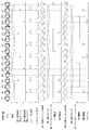
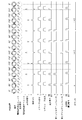
- FIG. 4 is a timing chart showing the operation of the multi-rotation information detection unit 3 when the rotation axis SF rotates counterclockwise (forward rotation).
- FIG. 5 is a timing chart showing the operation of the multi-rotation information detection unit 3 when the rotation axis SF rotates counterclockwise (reverse rotation).
- the solid line indicates the magnetic field at the position of the first electric signal generation unit 31a
- the broken line indicates the magnetic field at the position of the second electric signal generation unit 31b.
- the “first electric signal generation unit” and the “second electric signal generation unit” indicate the output of the first electric signal generation unit 31a and the output of the second electric signal generation unit 31b, respectively, and flow in one direction.
- the output of the current was positive (+), and the output of the current flowing in the opposite direction was negative ( ⁇ ).
- the “enable signal” indicates a potential applied to the control terminal 63a of the regulator 63 by an electrical signal generated by the electrical signal generation unit 31, and a high level is represented by “H” and a low level is represented by “L”.
- “Regulator” indicates the output of the regulator 63, the high level is represented by “H”, and the low level is represented by “L”.
- the “magnetic field on the first magnetic sensor” and the “magnetic field on the second magnetic sensor” are a magnetic field formed on the magnetic sensor 51 and a magnetic field formed in the shape of the magnetic sensor 52.
- the magnetic field formed by the magnet 11 is indicated by a long broken line
- the magnetic field formed by the bias magnet is indicated by a short broken line
- the combined magnetic field is indicated by a solid line.
- First magnetic sensor” and “second magnetic sensor” indicate outputs when the magnetic sensor 51 and the magnetic sensor 52 are always driven, respectively, and the output from the first output terminal is indicated by a broken line, and the second output terminal.
- the output from is represented by a solid line.
- First analog comparator and “second analog comparator” indicate outputs from the analog comparator 65 and the analog comparator 66, respectively.
- the output when the magnetic sensor and the analog comparator are always driven is shown as “always drive”, and the output when the magnetic sensor and the analog comparator are intermittently driven is shown as “intermittent drive”.
- the first electric signal generation unit 31a outputs a current pulse flowing in the reverse direction (negative of the “first electric signal generation unit”) at an angular position of 135 °.
- the first electric signal generation unit 31a outputs a current pulse that flows in the forward direction (positive of the “first electric signal generation unit”) at an angular position of 315 °.
- the second electric signal generation unit 31b outputs a current pulse (positive of “second electric signal generation unit”) flowing in the forward direction at an angular position of 45 °.
- the second electric signal generating unit 31b outputs a current pulse flowing in the opposite direction (negative of the “second electric signal generating unit”) at the angular position 225 °. Therefore, the enable signal switches to a high level at each of the angular position 45 °, the angular position 135 °, the angular position 225 °, and the angular position 315 °. Further, the regulator 63 corresponds to a state in which the enable signal is maintained at a high level, and a predetermined voltage is applied to the power supply line PL at each of the angular position 45 °, the angular position 135 °, the angular position 225 °, and the angular position 315 °. Supply.
- the output of the magnetic sensor 51 and the output of the magnetic sensor 52 have a phase difference of 90 °, and the detection unit 13 detects rotational position information using this phase difference.
- the output of the magnetic sensor 51 is a positive sine wave in the range from the angular position 0 ° to the angular position 180 °.
- the regulator 63 outputs power at an angular position of 45 ° and an angular position of 135 °.
- the magnetic sensor 51 and the analog comparator 65 are driven by electric power supplied at each of the angular position 45 ° and the angular position 135 °.
- a signal output from the analog comparator 65 (hereinafter referred to as an A-phase signal) is maintained at the L level in a state where power is not supplied, and is at the H level at each of the angular position 45 ° and the angular position 135 °. .
- the output of the magnetic sensor 52 is a positive sine wave in the range from the angular position 270 ° ( ⁇ 90 °) to the angular position 90 °.
- the regulator 63 outputs power at the angular position 315 ° ( ⁇ 45 °) and the angular position 45 °.
- the magnetic sensor 52 and the analog comparator 66 are driven by electric power supplied at each of the angular position 315 ° and the angular position 45 °.
- a signal output from the analog comparator 66 (hereinafter referred to as a B-phase signal) is maintained at the L level in a state where power is not supplied, and is at the H level at each of the angular position 315 ° and the angular position 45 °. .
- the set of these signal levels is expressed as (H, L ).
- a set of signal levels is (L, H) at an angular position of 315 °
- a set of signal levels is (H, H) at an angular position of 45 °
- a set of signal levels is (H, H) at an angular position of 135 °. , L).
- the counter 67 causes the storage unit 14 to store a set of signal levels when one or both of the detected A-phase signal and B-phase signal are at the H level. When one or both of the next detected A-phase signal and B-phase signal are at the H level, the counter 67 reads the previous level set from the storage unit 14 and sets the previous level set and the current level. The direction of rotation is determined by comparison with the set.
- the angle position is 45 ° in the previous detection, and the angle in the current detection is Since it is 135 degrees, it turns out that it is counterclockwise (forward rotation).
- the counter 67 outputs an up signal indicating that the counter is to be increased to the storage unit 14. Supply.
- the storage unit 14 detects an up signal from the counter 67, the storage unit 14 updates the stored multi-rotation information to a value increased by one.
- the first electric signal generation unit 31a outputs a current pulse flowing forward (positive of “first electric signal generation unit”) at an angular position of 135 °.
- the first electric signal generation unit 31a outputs a current pulse flowing in the reverse direction (negative of the “first electric signal generation unit”) at the angular position 315 °.
- the second electric signal generation unit 31b outputs a current pulse flowing in the reverse direction (negative of the “second electric signal generation unit”) at an angular position of 45 °.
- the second electric signal generation unit 31b outputs a current pulse (positive of “second electric signal generation unit”) that flows in the forward direction at the angular position of 225 °.
- the regulator 63 supplies a predetermined voltage to the power supply line PL at each of the angular position 45 °, the angular position 135 °, the angular position 225 °, and the angular position 315 °.
- the counter 67 determines the rotation direction in the same manner as described for forward rotation. Further, when the set of the current signal level is (H, L) and the previous signal level is (L, H), the angle position is 315 ° ( ⁇ 45 °) in the previous detection, Since the angular position is 135 ° ( ⁇ 225 °) in this detection, it can be seen that the rotation is clockwise (reverse rotation).
- the counter 67 stores a down signal indicating that the counter is down when the current level set is (H, L) and the previous level set is (L, H). To supply. When the storage unit 14 detects a down signal from the counter 67, the storage unit 14 updates the stored multi-rotation information to a value reduced by one.
- the multi-rotation information detection unit 3 can detect multi-rotation information while determining the rotation direction of the rotation axis SF.
- the encoder device EC As described above, in the encoder device EC according to the present embodiment, power is supplied from the battery 32 to the multi-rotation information detection unit 3 within a short time after the electrical signal is generated in the electrical signal generation unit 31, and the multi-rotation is detected.
- the information detection unit 3 performs dynamic driving (intermittent driving). After the end of detection and writing of the multi-rotation information, the power supply to the multi-rotation information detection unit 3 is cut off, but the count value is retained because it is stored in the storage unit 14. Such a sequence is repeated each time a predetermined position on the magnet 11 passes in the vicinity of the electric signal generating unit 31 even in a state where the external power supply is cut off.
- the multi-rotation information stored in the storage unit 14 is read to the motor control unit MC and the like when the motor M is started next time, and is used for calculating the initial position of the rotation axis SF and the like.
- the battery 32 supplies at least a part of the power consumed by the position detection system 1 in accordance with the electric signal generated by the first electric signal generating unit 31, so that the battery 32 has a long life. Can be. Maintenance (eg, replacement) of the battery 32 can be eliminated, or the frequency of maintenance can be reduced. For example, when the life of the battery 32 is longer than the life of other parts of the encoder device EC, the replacement of the battery 32 can be made unnecessary.
- a pulse current output can be obtained from the electric signal generating unit 31 even if the rotation of the magnet 11 is extremely low. Therefore, for example, in the state where electric power is not supplied to the motor M, the output of the electric signal generation unit 31 can be used as an electric signal even when the rotation of the rotating shaft SF (magnet 11) is extremely low.
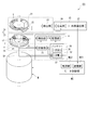
- FIG. 6 is a diagram showing an encoder device EC according to the present embodiment.
- the battery 32 includes a primary battery 36 and a secondary battery 37.
- the motor control unit MC includes a power supply unit MC2, and the secondary battery 37 is charged with electric power supplied from the power supply unit MC2.
- the power supply unit MC2 is a power supply that supplies power used to drive the rotating shaft SF (moving unit), for example, and supplies power to the motor M.
- the secondary battery 37 may be charged by receiving power supply from the power supply unit MC2 in a state where the power supply unit MC2 can supply power to the motor M (eg, the main power supply is on). In addition, in a state where the power supply unit MC2 does not supply power to the motor M (eg, a state where the main power supply is off), at least a part of the charge to the secondary battery 37 is an electric signal generation unit (electric signal generation unit) It may be performed using the electric power of the electric signal generated in 31). In this case, the secondary battery 37 can be charged even in a state where supply of electric power from the outside to the encoder device EC is cut off (eg, power failure).
- an electric signal generation unit electric signal generation unit
- the battery 32 can supply at least a part of the power consumed by the position detection system 1 from the primary battery 36 or can be supplied from the secondary battery 37.
- the primary battery 36 and the secondary battery 37 are each electrically connected to the switching unit 33, and the switching unit 33 stores the power from the primary battery 36 or the power from the secondary battery 37 and the storage unit 13. Supply to each of the parts 14.
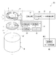
- FIG. 7 is a diagram showing an encoder device EC according to the present embodiment.
- the secondary battery 37 is electrically connected to the power supply unit MC2 of the motor control unit MC. Power is supplied from the power supply unit MC2 to the secondary battery 37 in at least a part of a period during which the power supply unit MC2 of the motor control unit MC can supply power (eg, the main power supply is in an on state). 37 is charged. In a period during which the power supply unit MC2 of the motor control unit MC cannot supply power (eg, the main power supply is off), the power supply from the power supply unit MC2 to the secondary battery 37 is cut off.
- the secondary battery 37 may be electrically connected to the transmission path of the electric signal from the electric signal generating unit 31.
- the secondary battery 37 can be charged by the electric power of the electric signal from the electric signal generating unit 31.
- the secondary battery 37 is electrically connected to a circuit between the rectifying stack 61 and the regulator 63.
- the secondary battery 37 can be charged by the electric power of the electric signal generated by the electric signal generating unit 31 due to the rotation of the rotating shaft SF in a state where the supply of electric power from the power supply unit MC2 is cut off.
- the secondary battery 37 may be charged with electric power of an electric signal generated by the electric signal generating unit 31 when the rotating shaft SF is driven by the motor M to rotate.
- the encoder device EC selects which of the primary battery 36 and the secondary battery 37 supplies power to the position detection system 1 in a state where power supply from the outside is cut off.
- the power supply system 2 includes a power switch (power selection unit, selection unit) 38, and the power switch 38 supplies power from either the primary battery 36 or the secondary battery 37 to the position detection system 1. Switch (select).
- the first input terminal of the power switch 38 is electrically connected to the positive electrode of the primary battery 36, and the second input terminal of the power switch 38 is electrically connected to the secondary battery 37.
- the output terminal of the power switch 38 is electrically connected to the input terminal 63 b of the regulator 63.
- the power switch 38 selects, for example, the primary battery 36 or the secondary battery 37 as a battery that supplies power to the position detection system 1 based on the remaining amount of the secondary battery 37. For example, when the remaining amount of the secondary battery 37 is greater than or equal to the threshold, the power switch 38 supplies power from the secondary battery 37 and does not supply power from the primary battery 36.
- This threshold is set based on the power consumed by the position detection system 1, and is set to be equal to or higher than the power to be supplied to the position detection system 1, for example. For example, when the power consumed by the position detection system 1 can be supplied by the power from the secondary battery 37, the power switch 38 supplies power from the secondary battery 37 and supplies power from the primary battery 36. I won't let you.
- the power switch 38 when the remaining amount of the secondary battery 37 is less than the threshold value, the power switch 38 does not supply power from the secondary battery 37 but supplies power from the primary battery 36.
- the power switch 38 may also serve as, for example, a charger that controls charging of the secondary battery 37, and uses the information on the remaining amount of the secondary battery 37 that is used for charging control. It may be determined whether the remaining amount is greater than or equal to a threshold value.
- the encoder device EC Since the encoder device EC according to the present embodiment uses the secondary battery 37 together, the consumption of the primary battery 36 can be delayed. Therefore, the encoder device EC has no maintenance (e.g., replacement) of the battery 32 or the maintenance frequency is low.
- the battery 32 may include at least one of the primary battery 36 and the secondary battery 37.
- power is alternatively supplied from the primary battery 36 or the secondary battery 37, but power may be supplied from the primary battery 36 and the secondary battery 37 in parallel.
- the processing unit to which the primary battery 36 supplies power and the secondary battery 37 according to the power consumption of each processing unit (eg, magnetic sensor 51, counter 67, nonvolatile memory 69) of the position detection system 1 A processing unit that supplies power may be defined.
- the secondary battery 37 may be charged using at least one of the power supplied from the power supply unit EC2 and the power of the electrical signal generated by the electrical signal generation unit 31.
- FIG. 8 is a diagram showing an encoder device EC according to the present embodiment.
- the multi-rotation information detection unit 3 detects rotational position information of the rotation axis SF (moving unit) magnetically in the first embodiment, but optically detects in the present embodiment.
- the multi-rotation information detection unit 3 includes a scale S, a light emitting element 21 (irradiation unit), and a light receiving sensor 22 (light detection unit).
- the scale S rotates in conjunction with the rotation axis SF.
- the light emitting element 21 irradiates the scale S with light.
- the light emitting element 21 irradiates the scale S with light using the power supplied from the battery 32 in a state where the power supply from the outside of the encoder device EC is cut off.
- the power supply system 2 intermittently supplies power to the light emitting element 21 in accordance with an electrical signal generated by the electrical signal generation unit 31 in a state where power supply from the outside of the encoder device EC is cut off.
- the light receiving sensor 22 detects light from the scale S.
- the light emitting element 21 detects light from the scale S in a state where power supply from the outside of the encoder device EC is cut off.
- the power supply system 2 intermittently supplies power to the light receiving sensor 22 in accordance with an electrical signal generated by the electrical signal generation unit 31 in a state where power supply from the outside of the encoder device EC is cut off.
- the detection unit 13 of the multi-rotation information detection unit 3 is communicably connected to the light receiving sensor 22 and acquires the detection result of the light receiving sensor 22.
- the detection unit 13 detects at least a part (eg, multi-rotation information) of the rotational position information of the rotation axis SF based on the detection result of the light receiving sensor 22.
- FIG. 9 is a diagram showing the magnet 11, the electric signal generating unit 31, the scale S, and the light receiving sensor 22 according to the present embodiment.
- a portion used for detecting multi-rotation information is illustrated, and illustration of a portion used for detecting angular position information (an incremental scale, an absolute scale, and a light receiving unit corresponding thereto) is omitted.
- the magnet 11 is, for example, a permanent magnet that is magnetized to 8 poles.
- the magnet 11 has a shape in which two concentric circular magnets are combined. Each of the two annular magnets is magnetized to 4 poles, and N and S poles are alternately arranged in the circumferential direction.
- the two annular magnets have N and S poles arranged in the radial direction (radial direction of the rotation axis SF).
- the scale S includes a first scale Sa and a second scale Sb.
- Each of the first scale Sa and the second scale Sb is an annular member centered on the rotation axis SF.
- Each of the first scale Sa and the second scale Sb varies in optical characteristics (eg, transmittance, reflectance, light absorption rate) depending on the circumferential angular position.
- the optical characteristics of the first scale Sa and the second scale Sb are switched in a binary manner in the circumferential direction with respect to the rotation axis SF.
- the angular position at which the optical characteristics are switched in a binary manner is set to be different from the angular position of the boundary between the N pole and the S pole in the circumferential direction of the magnet 11.
- the second scale Sb is the same as the first scale Sa, but has a different phase in which optical characteristics change in the circumferential direction as compared to the first scale Sa.
- the phase difference between the optical characteristics of the first scale Sa and the second scale Sb is set in a range larger than 0 ° and smaller than 180 °, for example, 90 °.
- the first scale Sa and the second scale Sb may be provided on a member different from the incremental scale and the absolute scale.
- the first scale Sa and the second scale Sb may be provided on the same disk 15 as the magnet 11.
- the light emitting element that irradiates light to the first scale Sa and the second scale Sb is provided separately from the light emitting element that irradiates light to the incremental scale and the absolute scale, for example.
- the light receiving sensor 22 includes a first light receiving unit 71 and a second light receiving unit 72.
- the first light receiving unit 71 is arranged at a position where light irradiated from the light emitting element 21 and passing through the first scale Sa (for example, transmitted) is incident.
- the transmittance of the first scale Sa changes in the circumferential direction, and the amount of light emitted from the light emitting element 21 and transmitted through the first scale Sa depends on the angular position of the first scale Sa (rotation axis SF).
- the amount of light that changes and enters the first light receiving unit 71 also changes according to the angular position of the first scale Sa (rotation axis SF).
- the second light receiving unit 72 is disposed at a position where light irradiated from the light emitting element 21 and passing through the second scale Sb (for example, transmitted) is incident.
- the second light receiving unit 72 is disposed at substantially the same angular position as the first light receiving unit 71 in the circumferential direction of the scale S.
- the transmittance of the second scale Sb changes in the circumferential direction, and the amount of light emitted from the light emitting element 21 and transmitted through the second scale Sb depends on the angular position of the second scale Sb (rotation axis SF).
- the amount of light that changes and enters the second light receiving unit 72 also changes according to the angular position of the second scale Sb (rotation axis SF).
- the detection unit 13 uses, for example, the detection result of the first light receiving unit 71 as the A phase signal, and the second light receiving unit 72
- the detection result can be used for the B phase signal.
- the first scale Sa and the second scale Sb have different optical characteristics and the angular positions of the first light receiving portion 71 and the second light receiving portion 72 are substantially the same.
- the scale Sa and the second scale Sb may have the same phase of change in optical characteristics, and the angular positions of the first light receiving unit 71 and the second light receiving unit 72 may be different.
- the detection result of the first light receiving unit 71 can be used for the A phase signal
- the detection result of the second light receiving unit 72 can be used for the B phase signal.
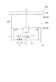
- FIG. 10 is a diagram illustrating a circuit configuration of the power supply system 2 and the multi-rotation information detection unit 3 according to the present embodiment.
- the light emitting element 21 emits light by the power supplied from the power supply system 2.
- the power supply terminal 21p of the light emitting element 21 is connected to the power supply line PL.
- the ground terminal 21g of the light emitting element 21 is connected to the ground line GL.
- the light emitting element 21 emits light by power supplied via the power supply terminal 21p and the ground terminal 21g.
- the multi-rotation information detection unit 3 includes a light receiving sensor 22, an analog comparator 75, and an analog comparator 76 as the detection unit 13 illustrated in FIG.
- the light receiving sensor 22 detects light by the power supplied from the power supply system 2.
- the power terminal 22p of the light receiving sensor 22 is connected to the power line PL.
- the ground terminal 22g of the light receiving sensor 22 is connected to the ground line GL.
- the light emitting element 21 emits light by electric power supplied through the power supply terminal 22p and the ground terminal 22g.
- the output terminal 22a of the light receiving sensor 22 outputs the detection result of the first light receiving unit 71 shown in FIG.
- the output terminal 22a is connected to the input terminal 75a of the analog comparator 75.
- the output terminal 22b of the light receiving sensor 22 outputs the detection result of the second light receiving unit 72 shown in FIG.
- the output terminal 22b is connected to the input terminal 76a of the analog comparator 76.
- the analog comparator 75 is a comparator that compares the voltage output from the first light receiving unit 71 of the light receiving sensor 22 with a predetermined voltage.
- a power supply terminal 75p of the analog comparator 75 is connected to the power supply line PL.
- the ground terminal 75g of the analog comparator 75 is connected to the ground line GL.
- the output terminal 75 b of the analog comparator 75 is connected to the first input terminal 67 a of the counter 67.
- the analog comparator 75 outputs an H level signal from the output terminal 75b when the output voltage of the first light receiving unit 71 is equal to or higher than the threshold value, and outputs an L level signal from the output terminal 75b when the output voltage is lower than the threshold value.
- the analog comparator 76 is a comparator that compares the voltage output from the second light receiving unit 72 of the light receiving sensor 22 with a predetermined voltage.
- a power supply terminal 76p of the analog comparator 76 is connected to the power supply line PL.
- the ground terminal 76g of the analog comparator 76 is connected to the ground line GL.
- the output terminal 76 b of the analog comparator 76 is connected to the second input terminal 67 b of the counter 67.
- the analog comparator 76 outputs an H level signal from the output terminal 76b when the output voltage of the second light receiving unit 72 is equal to or higher than the threshold value, and outputs an L level signal from the output terminal 76b when the output voltage is less than the threshold value.
- FIG. 11 is a diagram illustrating the operation of the multi-rotation information detection unit according to the present embodiment.
- Magnetic in FIG. 11 is an angular position of the magnet according to the angular position of the rotation axis SF, and the N pole and the S pole are indicated by different hatching.
- Electrical signal generating unit, light receiving element is an angular position of the electric signal generating unit 31 and the light receiving sensor 22, and is constant regardless of the angular position of the rotation axis SF.
- the “electric signal generating unit” is an output of the electric signal generating unit 31, and an output of a current flowing in one direction is positive (+), and an output of a current flowing in the opposite direction is negative ( ⁇ ).
- the output of the electric signal generating unit 31 when the rotating shaft SF rotates counterclockwise is shown as “counterclockwise”, and the output of the electric signal generating unit 31 when the rotating shaft SF rotates clockwise is “ “Clockwise”.
- the “enable signal” indicates a potential applied to the control terminal 63a of the regulator 63 by an electrical signal generated by the electrical signal generation unit 31, and a high level is represented by “H” and a low level is represented by “L”.
- “Regulator” indicates the output of the regulator 63, the high level is represented by “H”, and the low level is represented by “L”.
- first output of light receiving element and “second output of light receiving element” are the output of the first light receiving unit 71 and the output of the second light receiving unit 72, respectively.
- First analog comparator and “second analog comparator” indicate outputs from the analog comparator 75 and the analog comparator 76, respectively. The output when the light receiving element and the analog comparator are always driven is shown as “always drive”, and the output when the magnetic sensor and the analog comparator are intermittently driven is shown as “intermittent drive”.
- the output of the electric signal generating unit 31 is inverted depending on the rotation direction of the rotating shaft SF.
- the enable signal is rotated counterclockwise by the rotating shaft SF. It is the same when rotating clockwise and when rotating clockwise.
- the enable signal rises to a high level (H) at the angular positions of 45 °, 135 °, 225 °, and 315 °.
- the output of the regulator 63 becomes high level (H) in response to the rise of the enable signal.
- the set of the output of the analog comparator 75 and the output of the analog comparator 76 is expressed as (0, 1), where H is “1” and L is “0”.
- the set of the output of the analog comparator 75 and the output of the analog comparator 76 are (1, 1), (1, 0), (0, 0), at the angular positions of 45 °, 135 °, 225 °, and 315 °, respectively. (0.1).
- the four angular positions can be distinguished from the set of the output of the analog comparator 75 and the output of the analog comparator 76.
- the counter 67 uses the output of the analog comparator 75 and the output of the analog comparator 76 to detect multi-rotation information of the rotation axis SF, for example, as in the first embodiment.
- the storage unit 14 stores the multi-rotation information detected by the counter 67.
- FIG. 12 is a diagram showing an encoder device EC according to the present embodiment.
- the battery 32 includes a primary battery 36 and a secondary battery 37.
- the motor control unit MC includes a power supply unit MC2, and the secondary battery 37 is charged with electric power supplied from the power supply unit MC2.
- the battery 32 and the power supply unit MC2 may be the same as those described in the second embodiment, for example.
- the battery 32 can supply at least a part of the power consumed by the position detection system 1 from the primary battery 36 or can be supplied from the secondary battery 37.
- FIG. 13 is a diagram showing an encoder device EC according to the present embodiment.
- the secondary battery 37 is supplied with power from the power supply unit MC2 and charged by this power in at least a part of a period during which the power supply unit MC2 of the motor control unit MC can supply power (eg, the main power supply is in an on state).
- the power supply from the power supply unit MC2 to the secondary battery 37 is cut off.
- the secondary battery 37 may be chargeable by the electric power of the electric signal from the electric signal generating unit 31.
- the encoder device EC selects which of the primary battery 36 and the secondary battery 37 supplies power to the position detection system 1 in a state where power supply from the outside is cut off. Since the encoder device EC according to the present embodiment uses the secondary battery 37 together, the consumption of the primary battery 36 can be delayed. Therefore, the encoder device EC has no maintenance (e.g., replacement) of the battery 32 or the maintenance frequency is low.
- FIGS. 14A to 14D are diagrams each showing a part of a modified encoder device.
- the magnet 11 generates an alternating magnetic field using a ring-shaped magnet (see FIG. 2), but the magnet 11 shown in FIG. 14A generates an alternating magnetic field using a bar magnet.
- the magnet 11 includes bar magnets 81a to 81f provided on a disk-shaped plate 80.
- the plate 80 is fixed to the rotating shaft SF and rotates integrally with the rotating shaft SF.
- the bar magnets 81a to 81f are fixed to the plate 80, and rotate integrally with the plate 80 and the rotation shaft SF.
- Each of the bar magnets 81a to 81f is disposed substantially parallel to the radial direction of the plate 80.
- the bar magnets 81a to 81c are arranged with the south pole facing the center (rotation axis SF) of the plate 80 and the north pole facing the radial direction (outside the plate 80) with respect to the rotation axis SF.
- the bar magnet 81a is disposed in the vicinity of the position 11d of the plate 80.
- the bar magnet 81 b is disposed at the position 11 a of the plate 80.
- the bar magnet 81 c is disposed in the vicinity of the position 11 b of the plate 80.
- the bar magnets 81d to 81f are arranged with the north pole facing the center of the plate 80 (rotation axis SF) and the south pole facing the radial direction with respect to the rotation axis SF (outside the plate 80).
- the bar magnet 81d is disposed near the position 11b of the plate 80 and adjacent to the bar magnet 81c.
- the bar magnet 81e is disposed at the position 11c of the plate 80.
- the bar magnet 81f is disposed near the position 11d of the plate 80 and adjacent to the bar magnet 81a.
- an electric signal generation unit 31a and an electric signal generation unit 31c are provided as the electric signal generation unit 31.
- the electrical signal generation unit 31 c is arranged with a phase difference of 180 ° from the electrical signal generation unit 31 in the circumferential direction of the magnet 11.
- the electric signal generation unit 31a and the electric signal generation unit 31c generate electric power almost simultaneously, and the electric power (electric signal level) generated in the electric signal generation unit 31 can be increased.
- an electric signal generation unit 31a and an electric signal generation unit 31d are provided as the electric signal generation unit 31.
- the electrical signal generation unit 31 c is provided on the opposite side of the electrical signal generation unit 31 a with respect to the magnet 11.
- the electrical signal generation unit 31 c is provided at the same angular position as the electrical signal generation unit 31 in the circumferential direction of the magnet 11.
- the electric signal generating unit 31 and the electric signal generating unit 31c generate electric power almost simultaneously, and it becomes easy to cover the electric power consumed by the detection system or the like.
- a magnet 82 and a magnet 83 are provided as the magnet 11. Further, as the electric signal generation unit 31, an electric signal generation unit 31a and an electric signal generation unit 31e are provided.
- the magnet 82 is disposed on the front surface of the disk 15 shown in FIG. 1 and the like, and the magnet 83 is disposed on the back surface.
- the electric signal generating unit 31a is disposed in the vicinity of the magnet 82 and generates power by changing the magnetic field formed by the magnet 82.
- the electric signal generation unit 31e is disposed in the vicinity of the magnet 83, and generates electric power by changing the magnetic field formed by the magnet 83.
- the power output from the electrical signal generation unit 31c may be used as a detection signal for detecting multi-rotation information.
- the number of electrical signal generation units provided in the encoder device EC may be three or more.
- the electric signal generating unit is provided with a magnetic sensitive part and a power generating part on each of the one surface side and the other surface side of the magnet 11, and the magnetic sensitive part and the power generating part are accommodated in one housing. It may be.
- the magnet 11 is a quadrupole magnet having two poles in the circumferential direction and two poles in the radial direction, but is not limited to such a configuration and can be changed as appropriate.
- the number of poles in the circumferential direction may be four or more, or the magnet 11 may be an eight-pole magnet having four poles in the circumferential direction and two poles in the radial direction.
- the position detection system 1 detects rotational position information of the rotation axis SF (moving unit) as position information, but detects at least one of a position, speed, and acceleration in a predetermined direction as position information. May be.
- the encoder device EC may include a rotary encoder or a linear encoder.
- the power generation unit and the detection unit are provided on the rotation shaft SF, and the magnet 11 is provided outside the moving body (eg, the rotation shaft SF), so that the relative position between the magnet and the detection unit moves. It may change as the part moves.
- the position detection system 1 may not detect the multi-rotation information of the rotation axis SF, and may detect the multi-rotation information by a processing unit outside the position detection system 1.
- the electric signal generating unit 31 generates electric power (electrical signal) when it has a predetermined positional relationship with the magnet 11.
- the position detection system 1 may detect position information of the moving unit (for example, the rotation axis SF) using a change in electric power generated in the electric signal generation unit 31 as a detection signal.
- the electric signal generation unit 31 may be used as a sensor, and the position detection system 1 detects the position information of the moving unit by the electric signal generation unit 31 and one or more sensors (eg, magnetic sensor, light receiving sensor). May be.
- the position detection system 1 may detect position information using two or more electrical signal generation units as sensors.
- the position detection system 1 may use two or more electric signal generation units as sensors, detect position information of the moving unit without using a magnetic sensor, or position of the moving unit without using a light receiving sensor. Information may be detected.
- the electric signal generation unit 31 may supply at least a part of the power consumed by the position detection system 1.
- the electrical signal generation unit 31 may supply power to a processing unit that consumes relatively little power in the position detection system 1.
- the power supply system 2 may not supply power to a part of the position detection system 1.
- the power supply system 2 may intermittently supply power to the detection unit 13 and may not supply power to the storage unit 14. In this case, power may be intermittently or continuously supplied to the storage unit 14 from a power supply, a battery, or the like provided outside the power supply system 2.
- the power generation unit may generate electric power due to a phenomenon other than a large Barkhausen jump.
- the power generation unit may generate electric power by electromagnetic induction accompanying a change in a magnetic field accompanying movement of a moving unit (eg, rotation axis SF).
- the storage unit that stores the detection result of the detection unit may be provided outside the position detection system 1 or may be provided outside the encoder device EC.
- FIG. 15 is a diagram illustrating an example of the driving device MTR.
- the drive device MTR is a motor device including an electric motor.
- the drive device MTR includes a rotary shaft SF, a main body (drive unit) BD that rotationally drives the rotary shaft SF, and an encoder device EC that detects rotational position information of the rotary shaft SF.
- the rotary shaft SF has a load side end SFa and an anti-load side end SFb.
- the load side end portion SFa is connected to another power transmission mechanism such as a speed reducer.
- the scale S is fixed to the non-load side end portion SFb through a fixing portion.
- an encoder device EC is attached.
- the encoder device EC is an encoder device according to the above-described embodiment, modification, or combination thereof.
- the motor control unit MC shown in FIG. 1 and the like controls the main body BD using the detection result of the encoder device EC. Since the drive device MTR has no or low need for battery replacement of the encoder device EC, the maintenance cost can be reduced.
- the drive device MTR is not limited to a motor device, and may be another drive device having a shaft portion that rotates using hydraulic pressure or pneumatic pressure.
- FIG. 16 is a diagram showing a stage apparatus STG.
- This stage device STG has a configuration in which a rotary table (moving object) TB is attached to the load side end portion SFa of the rotation shaft SF of the drive device MTR shown in FIG.
- components that are the same as or equivalent to those in the above-described embodiment are denoted by the same reference numerals, and description thereof is omitted or simplified.
- the stage device STG rotates the rotating shaft SF by driving the driving device MTR, this rotation is transmitted to the rotary table TB.
- the encoder device EC detects the angular position and the like of the rotating shaft SF. Therefore, the angular position of the rotary table TB can be detected by using the output from the encoder device EC.
- a reduction gear or the like may be disposed between the load side end SFa of the drive device MTR and the rotary table TB.
- the stage apparatus STG can reduce the maintenance cost because the necessity of replacing the battery of the encoder apparatus EC is low or absent.
- the stage apparatus STG can be applied to a rotary table provided in a machine tool such as a lathe.
- FIG. 17 is a perspective view showing the robot apparatus RBT.
- FIG. 17 schematically shows a part (joint part) of the robot apparatus RBT.
- the robot apparatus RBT includes a first arm AR1, a second arm AR2, and a joint portion JT.
- the first arm AR1 is connected to the second arm AR2 via the joint portion JT.
- the first arm AR1 includes an arm portion 101, a bearing 101a, and a bearing 101b.
- the second arm AR2 has an arm portion 102 and a connection portion 102a.
- the connecting portion 102a is disposed between the bearing 101a and the bearing 101b in the joint portion JT.
- the connecting portion 102a is provided integrally with the rotation shaft SF2.
- the rotation shaft SF2 is inserted into both the bearing 101a and the bearing 101b in the joint portion JT.
- the end of the rotary shaft SF2 on the side inserted into the bearing 101b passes through the bearing 101b and is connected to the speed reducer RG.
- the reduction gear RG is connected to the drive device MTR, and decelerates the rotation of the drive device MTR to, for example, 1/100 and transmits it to the rotary shaft SF2.
- the load side end portion SFa of the rotation shaft SF of the drive device MTR is connected to the speed reducer RG.
- the scale S of the encoder device EC is attached to the non-load-side end portion SFb of the rotation shaft SF of the drive device MTR.
- the robot apparatus RBT drives the drive apparatus MTR to rotate the rotation axis SF
- the rotation is transmitted to the rotation axis SF2 via the reduction gear RG.
- the connecting portion 102a rotates integrally, whereby the second arm AR2 rotates relative to the first arm AR1.
- the encoder device EC detects the angular position and the like of the rotating shaft SF. Therefore, the angular position of the second arm AR2 can be detected by using the output from the encoder device EC.
- the robot apparatus RBT does not require or is low in battery replacement of the encoder apparatus EC, the maintenance cost can be reduced.
- the robot apparatus RBT is not limited to the above configuration, and the drive apparatus MTR can be applied to various robot apparatuses having joints.
- switch 67 ... counter, EC ... encoder device, SF ... rotary shaft , AR1 ... first arm, AR2 ... second arm, MTR ... drive device, RBT ... robot device, S ... su Lumpur, STG ⁇ stage device
Abstract
Description
第1実施形態について説明する。図1は、本実施形態に係るエンコーダ装置ECを示す図である。このエンコーダ装置ECは、モータM(動力供給部)の回転軸SF(移動部)の回転位置情報を検出する。回転軸SFは、例えばモータMのシャフト(回転子)であるが、モータMのシャフトに変速機などの動力伝達部を介して接続されるとともに負荷に接続される作用軸(出力軸)であってもよい。エンコーダ装置ECが検出した回転位置情報は、モータ制御部MCに供給される。モータ制御部MCは、エンコーダ装置ECから供給された回転位置情報を使って、モータMの回転を制御する。モータ制御部MCは、回転軸SFの回転を制御する。
第2実施形態について説明する。本実施形態において、上述の実施形態と同様の構成については、同じ符号を付してその説明を省略あるいは簡略化する。図6は、本実施形態に係るエンコーダ装置ECを示す図である。本実施形態において、バッテリー32は、一次電池36および二次電池37を含む。モータ制御部MCは電源部MC2を備え、二次電池37は、電源部MC2から供給される電力により充電される。電源部MC2は、例えば、回転軸SF(移動部)の駆動に使われる電力を供給する電源であり、モータMに対して電力を供給する。二次電池37は、電源部MC2がモータMに対して電力を供給可能な状態(例、主電源がオンの状態)において、電源部MC2から電力の供給を受けて充電されてもよい。また、電源部MC2がモータMに対して電力を供給しない状態(例、主電源がオフの状態)において、二次電池37への充電の少なくとも一部は、電気信号発生部(電気信号発生ユニット31)で発生する電気信号の電力を用いて行われてもよい。この場合、エンコーダ装置ECに対して外部からの電力の供給が絶たれた状態(例、停電)などにおいても、二次電池37を充電することができる。
第3実施形態について説明する。本実施形態において、上述の実施形態と同様の構成については、同じ符号を付してその説明を省略あるいは簡略化する。図8は、本実施形態に係るエンコーダ装置ECを示す図である。多回転情報検出部3は、回転軸SF(移動部)の回転位置情報を、第1実施形態では磁気的に検出するが、本実施形態では光学的に検出する。
第4実施形態について説明する。本実施形態において、上述の実施形態と同様の構成については、同じ符号を付してその説明を省略あるいは簡略化する。図12は、本実施形態に係るエンコーダ装置ECを示す図である。本実施形態において、バッテリー32は、一次電池36および二次電池37を含む。モータ制御部MCは電源部MC2を備え、二次電池37は、電源部MC2から供給される電力により充電される。バッテリー32、電源部MC2は、例えば第2実施形態で説明したものと同様でよい。バッテリー32は、位置検出系1で消費される電力の少なくとも一部を、一次電池36から供給することもできるし、二次電池37から供給することもできる。
次に、駆動装置について説明する。図15は、駆動装置MTRの一例を示す図である。以下の説明において、上記した実施形態と同一または同等の構成部分については同一符号を付けて説明を省略または簡略化する。この駆動装置MTRは、電動モータを含むモータ装置である。駆動装置MTRは、回転軸SFと、回転軸SFを回転駆動する本体部(駆動部)BDと、回転軸SFの回転位置情報を検出するエンコーダ装置ECとを有している。
次に、ステージ装置について説明する。図16は、ステージ装置STGを示す図である。このステージ装置STGは、図15に示した駆動装置MTRの回転軸SFのうち負荷側端部SFaに、回転テーブル(移動物体)TBを取り付けた構成である。以下の説明において、上記した実施形態と同一または同等の構成部分については同一符号を付けて説明を省略または簡略化する。
次に、ロボット装置について説明する。図17は、ロボット装置RBTを示す斜視図である。なお、図17には、ロボット装置RBTの一部(関節部分)を模式的に示した。以下の説明において、上記した実施形態と同一または同等の構成部分については同一符号を付けて説明を省略または簡略化する。このロボット装置RBTは、第1アームAR1と、第2アームAR2と、関節部JTとを有している。第1アームAR1は、関節部JTを介して、第2アームAR2と接続されている。
Claims (29)
- 移動部の位置情報を検出する検出部を含む位置検出系と、
前記移動部の移動によって電気信号が発生する電気信号発生部と、
前記電気信号発生部で発生する電気信号に応じて、前記位置検出系で消費される電力の少なくとも一部を供給するバッテリーと、を備えるエンコーダ装置。 - 前記電気信号発生部で発生する電気信号に応じて、前記バッテリーから前記位置検出系への電力の供給の有無を切り替える切替部を備える、請求項1に記載のエンコーダ装置。
- 前記切替部は、
前記電気信号発生部で発生する電気信号のレベルが閾値以上になることで前記バッテリーから前記位置検出系への電力の供給を開始させ、
前記電気信号発生部で発生する電気信号のレベルが閾値未満になることで前記バッテリーから前記位置検出系への電力の供給を停止させる、請求項2に記載のエンコーダ装置。 - 前記電気信号発生部は、前記移動部の移動によってパルス状の電力を発生する、請求項3に記載のエンコーダ装置。
- 前記切替部は、前記バッテリーと前記位置検出系との間の電力の供給経路に設けられるスイッチを含み、
前記電気信号発生部で発生する電気信号をもとに前記スイッチの動作を制御する、請求項2から請求項4のいずれか一項に記載のエンコーダ装置。 - 前記切替部は、前記バッテリーから前記位置検出系へ供給される電力を調整するレギュレータを備え、
前記レギュレータは、前記スイッチを含み、
前記電気信号発生部で発生する電気信号を前記レギュレータに対する制御信号に用いる、請求項5に記載のエンコーダ装置。 - 前記バッテリーは、一次電池を含む、請求項1から請求項6のいずれか一項に記載のエンコーダ装置。
- 前記バッテリーは、二次電池を含む、請求項1から請求項7のいずれか一項に記載のエンコーダ装置。
- 前記二次電池への充電の少なくとも一部は、電気信号発生部で発生する電気信号の電力を用いて行われる、請求項8に記載のエンコーダ装置。
- 前記バッテリーは、一次電池を含み、
前記一次電池と前記二次電池とのいずれから前記位置検出系へ電力を供給するかを選択する選択部を備える、請求項8または請求項9に記載のエンコーダ装置。 - 前記選択は、前記二次電池の残量に基づいて行われる、請求項10に記載のエンコーダ装置。
- 前記位置検出系の少なくとも一部と前記バッテリーとを保持する保持部を備える、請求項1から請求項11のいずれか一項に記載のエンコーダ装置。
- 前記検出部は、前記バッテリーから供給される電力を用いて前記位置情報を検出する、請求項1から請求項12のいずれか一項に記載のエンコーダ装置。
- 前記検出部は、前記移動部の移動によって互いの相対位置が変化する磁石および磁気検出部を含み、前記磁石が形成する磁界に基づいて前記位置情報を検出し、
前記磁気検出部は、前記磁石が形成する磁界を前記バッテリーから供給される電力を用いて検出する、請求項13に記載のエンコーダ装置。 - 前記検出部は、
前記移動部と連動して移動するスケールと、
前記バッテリーから供給される電力を用いて前記スケールに光を照射する照射部と、
前記バッテリーから供給される電力を用いて前記スケールからの光を検出する光検出部と、を含む、請求項13または請求項14に記載のエンコーダ装置。 - 前記移動部は回転軸を含み、
前記検出部は、前記回転軸の1回転以内の角度位置情報を検出する角度検出部と、
前記位置情報として前記回転軸の多回転情報を検出する多回転情報検出部と、を備える請求項1から請求項11のいずれか一項に記載のエンコーダ装置。 - 前記多回転情報検出部は、前記回転軸の多回転情報を前記バッテリーから供給される電力を用いて計数する計数部を含む、請求項16に記載のエンコーダ装置。
- 前記位置検出系は、前記検出部が検出した前記位置情報を、前記バッテリーから供給される電力を用いて記憶する記憶部を含む、請求項1から請求項17のいずれか一項に記載のエンコーダ装置。
- 前記電気信号発生部は、
前記移動部と連動して移動する磁石と、
前記磁石の移動に伴う磁界の変化によって大バルクハウゼンジャンプを生じる感磁性部と、を含む、請求項1から請求項18のいずれか一項に記載のエンコーダ装置。 - 前記検出部は、前記磁石が形成する磁界を前記バッテリーから供給される電力を用いて検出する磁気検出部を含み、前記磁気検出部により前記移動部の位置情報を検出する、請求項19に記載のエンコーダ装置。
- 前記移動部は、回転軸を含み、
前記感磁性部は、前記磁石が形成する磁界を感じる第1感磁性部および第2感磁性部を含み、
前記磁気検出部は、前記回転軸の回転方向に配置される第1磁気センサおよび第2磁気センサを含み、
前記第2感磁性部は、前記回転軸の回転方向において、前記第1感磁性部に対して0°より大きく180°未満の角度位置で配置され、
前記第1磁気センサは、前記回転軸の回転方向において、前記第1感磁性部に対して0°より大きく90°未満の角度位置で配置され、
前記第2磁気センサは、前記回転軸の回転方向において、前記第1感磁性部に対して90°より大きく180°未満の角度位置で配置される、請求項20に記載のエンコーダ装置。 - 電力供給によって移動部の位置情報を検出する位置検出部と、
前記移動部の移動によって信号を出力する信号発生部と、を備え、
出力される前記信号に基づいて前記位置検出部に電力が供給される、エンコーダ装置。 - 前記信号に基づいて、バッテリーから前記位置検出部への電力供給の有無を切り替える切替部を備える、請求項22に記載のエンコーダ装置。
- 前記位置検出部に電力を供給する前記バッテリーを備える、請求項23に記載のエンコーダ装置。
- 前記信号発生部とは異なる電力供給部から前記位置検出部に電力が供給される、請求項22から請求項24のいずれか一項に記載のエンコーダ装置。
- 前記信号発生部とは異なる位置に配置され、前記位置検出部に電力を供給する電力供給部を備える、請求項22から請求項25のいずれか一項に記載のエンコーダ装置。
- 請求項1から請求項26のいずれか一項に記載のエンコーダ装置と、
前記移動部に動力を供給する動力供給部と、
を備える駆動装置。 - 移動物体と、
前記移動物体を移動させる請求項27に記載の駆動装置と、を備えるステージ装置。 - 請求項27に記載の駆動装置と、
前記駆動装置によって相対移動する第1アームおよび第2アームと、を備えるロボット装置。
Priority Applications (4)
| Application Number | Priority Date | Filing Date | Title |
|---|---|---|---|
| EP17741218.6A EP3407025B1 (en) | 2016-01-18 | 2017-01-06 | Encoder device, drive device, stage device, and robot device |
| JP2017562508A JP6773050B2 (ja) | 2016-01-18 | 2017-01-06 | エンコーダ装置、駆動装置、ステージ装置、及びロボット装置 |
| CN201780006980.8A CN108474673B (zh) | 2016-01-18 | 2017-01-06 | 编码器装置、驱动装置、载物台装置及机器人装置 |
| US16/036,380 US11243096B2 (en) | 2016-01-18 | 2018-07-16 | Encoder apparatus, drive apparatus, stage apparatus, and robot apparatus |
Applications Claiming Priority (2)
| Application Number | Priority Date | Filing Date | Title |
|---|---|---|---|
| JP2016-007468 | 2016-01-18 | ||
| JP2016007468 | 2016-01-18 |
Related Child Applications (1)
| Application Number | Title | Priority Date | Filing Date |
|---|---|---|---|
| US16/036,380 Continuation US11243096B2 (en) | 2016-01-18 | 2018-07-16 | Encoder apparatus, drive apparatus, stage apparatus, and robot apparatus |
Publications (1)
| Publication Number | Publication Date |
|---|---|
| WO2017126338A1 true WO2017126338A1 (ja) | 2017-07-27 |
Family
ID=59361571
Family Applications (1)
| Application Number | Title | Priority Date | Filing Date |
|---|---|---|---|
| PCT/JP2017/000284 WO2017126338A1 (ja) | 2016-01-18 | 2017-01-06 | エンコーダ装置、駆動装置、ステージ装置、及びロボット装置 |
Country Status (5)
| Country | Link |
|---|---|
| US (1) | US11243096B2 (ja) |
| EP (1) | EP3407025B1 (ja) |
| JP (2) | JP6773050B2 (ja) |
| CN (2) | CN108474673B (ja) |
| WO (1) | WO2017126338A1 (ja) |
Cited By (7)
| Publication number | Priority date | Publication date | Assignee | Title |
|---|---|---|---|---|
| JP2019045450A (ja) * | 2017-09-07 | 2019-03-22 | 株式会社ニコン | エンコーダ装置、駆動装置、ステージ装置、及びロボット装置 |
| WO2019139023A1 (ja) * | 2018-01-15 | 2019-07-18 | 株式会社ニコン | エンコーダ装置、駆動装置、ステージ装置、及びロボット装置 |
| KR20200123037A (ko) * | 2020-05-20 | 2020-10-28 | 현대모비스 주식회사 | 라이다 센서 안정화 장치 |
| KR20200122543A (ko) * | 2019-04-18 | 2020-10-28 | 현대모비스 주식회사 | 라이다 센서 안정화 장치 및 방법 |
| JP2021071425A (ja) * | 2019-10-31 | 2021-05-06 | 株式会社ニコン | エンコーダ装置及びその使用方法、駆動装置、ステージ装置、並びにロボット装置 |
| JP2022519668A (ja) * | 2019-02-06 | 2022-03-24 | フラバ ベスローテン ヴェンノーツハップ | 磁気センサ装置 |
| EP4071445A1 (en) | 2021-04-09 | 2022-10-12 | Kabushiki Kaisha Yaskawa Denki | Encoder, servo motor, servo system, and encoder control method |
Families Citing this family (5)
| Publication number | Priority date | Publication date | Assignee | Title |
|---|---|---|---|---|
| CN110165311B (zh) * | 2018-02-14 | 2020-11-27 | 车王电子股份有限公司 | 电池包 |
| US10612946B2 (en) | 2018-05-30 | 2020-04-07 | Rockwell Automation Technologies, Inc. | Encoder system for position determination with inclined scale |
| US11865714B2 (en) * | 2019-02-17 | 2024-01-09 | Samsung Electronics Co., Ltd. | Robotic limb |
| CN110345976B (zh) * | 2019-07-26 | 2020-03-27 | 浙江禾川科技股份有限公司 | 一种光磁混合编码器系统 |
| FR3123118B1 (fr) * | 2021-05-20 | 2023-10-20 | Vitesco Technologies | Dispositif de détection de position pour véhicule |
Citations (3)
| Publication number | Priority date | Publication date | Assignee | Title |
|---|---|---|---|---|
| JPH01136020A (ja) * | 1987-11-24 | 1989-05-29 | Mitsubishi Electric Corp | ロータリエンコーダ |
| JP2007292608A (ja) * | 2006-04-25 | 2007-11-08 | Fanuc Ltd | アブソリュートエンコーダ用バックアップ電源 |
| JP2008014799A (ja) * | 2006-07-06 | 2008-01-24 | Yaskawa Electric Corp | 絶対値エンコーダ装置 |
Family Cites Families (22)
| Publication number | Priority date | Publication date | Assignee | Title |
|---|---|---|---|---|
| JPH01248019A (ja) | 1988-03-29 | 1989-10-03 | Toshiba Corp | 磁気エンコーダ |
| JPH03276016A (ja) * | 1990-03-27 | 1991-12-06 | Mitsubishi Electric Corp | 磁気式エンコーダ |
| JPH0850034A (ja) | 1994-08-05 | 1996-02-20 | Nikon Corp | 多回転アブソリュートエンコーダ |
| US6119610A (en) * | 1998-02-27 | 2000-09-19 | Mitsubishi Denki Kabushiki Kaisha | Sewing machine controller |
| EP1329727A1 (en) * | 2001-10-18 | 2003-07-23 | Nsk Ltd | Rotation-speed sensor device |
| US6583603B1 (en) * | 2002-02-08 | 2003-06-24 | Peco Ii, Inc. | Back-up battery management apparatus and method for charging and testing battery cells in a string of battery cells |
| CN1289911C (zh) * | 2002-03-08 | 2006-12-13 | Ntn株式会社 | 旋转检测器和采用它的防锁制动装置 |
| JP4060133B2 (ja) * | 2002-06-27 | 2008-03-12 | 株式会社ハイレックスコ−ポレ−ション | パルスエンコーダ |
| US7635975B2 (en) | 2004-05-21 | 2009-12-22 | Kabushiki Kaisha Yaskawa Denki | Absolute multi-revolution encoder |
| CN100570283C (zh) * | 2005-06-29 | 2009-12-16 | 精工爱普生株式会社 | 压电致动器的驱动量检测装置及电子设备 |
| JP4953653B2 (ja) * | 2006-02-15 | 2012-06-13 | 株式会社ミツトヨ | 光電式エンコーダ |
| DE102007007764A1 (de) * | 2007-02-16 | 2008-08-21 | Dr. Johannes Heidenhain Gmbh | Drehgeber und Verfahren zu dessen Betrieb |
| JP4617368B2 (ja) * | 2008-03-25 | 2011-01-26 | 山洋電気株式会社 | バッテリレス絶対位置検出用エンコーダ |
| JP5176714B2 (ja) * | 2008-06-19 | 2013-04-03 | 株式会社ニコン | バックアップ電源装置を備えたエンコーダ |
| EP2309230A1 (de) * | 2009-10-12 | 2011-04-13 | Baumer Innotec AG | Positionsgebervorrichtung mit Energiesparmodus |
| JP2012008024A (ja) * | 2010-06-25 | 2012-01-12 | Panasonic Corp | 多回転検出回路 |
| US8760100B2 (en) * | 2010-10-12 | 2014-06-24 | Oceaneering International, Inc. | Electric manipulator joint |
| JP2012165577A (ja) * | 2011-02-08 | 2012-08-30 | Seiko Epson Corp | 相対駆動装置、移動体、及びロボット |
| WO2013146371A1 (ja) * | 2012-03-30 | 2013-10-03 | 株式会社デンソーウェーブ | エンコーダ、エンコーダの取り付け方法、トルク制限機構、駆動装置及びロボット装置 |
| DE112013002075T5 (de) * | 2012-04-17 | 2015-01-22 | Mitsubishi Electric Corp. | Multirotations-Drehgeber |
| JP2014013163A (ja) | 2012-07-04 | 2014-01-23 | Yaskawa Electric Corp | エンコーダ及びモータ |
| CN106662468B (zh) * | 2014-08-08 | 2019-02-05 | 广濑电机株式会社 | 旋转检测装置 |
-
2017
- 2017-01-06 CN CN201780006980.8A patent/CN108474673B/zh active Active
- 2017-01-06 JP JP2017562508A patent/JP6773050B2/ja active Active
- 2017-01-06 EP EP17741218.6A patent/EP3407025B1/en active Active
- 2017-01-06 WO PCT/JP2017/000284 patent/WO2017126338A1/ja active Application Filing
- 2017-01-06 CN CN202110380209.5A patent/CN113091779A/zh active Pending
-
2018
- 2018-07-16 US US16/036,380 patent/US11243096B2/en active Active
-
2020
- 2020-10-01 JP JP2020166959A patent/JP2020204625A/ja active Pending
Patent Citations (3)
| Publication number | Priority date | Publication date | Assignee | Title |
|---|---|---|---|---|
| JPH01136020A (ja) * | 1987-11-24 | 1989-05-29 | Mitsubishi Electric Corp | ロータリエンコーダ |
| JP2007292608A (ja) * | 2006-04-25 | 2007-11-08 | Fanuc Ltd | アブソリュートエンコーダ用バックアップ電源 |
| JP2008014799A (ja) * | 2006-07-06 | 2008-01-24 | Yaskawa Electric Corp | 絶対値エンコーダ装置 |
Cited By (19)
| Publication number | Priority date | Publication date | Assignee | Title |
|---|---|---|---|---|
| JP2019045450A (ja) * | 2017-09-07 | 2019-03-22 | 株式会社ニコン | エンコーダ装置、駆動装置、ステージ装置、及びロボット装置 |
| JP7047287B2 (ja) | 2017-09-07 | 2022-04-05 | 株式会社ニコン | エンコーダ装置、駆動装置、ステージ装置、及びロボット装置 |
| WO2019139023A1 (ja) * | 2018-01-15 | 2019-07-18 | 株式会社ニコン | エンコーダ装置、駆動装置、ステージ装置、及びロボット装置 |
| CN111602032A (zh) * | 2018-01-15 | 2020-08-28 | 株式会社尼康 | 编码器装置、驱动装置、载台装置、以及机械手装置 |
| US11858132B2 (en) | 2018-01-15 | 2024-01-02 | Nikon Corporation | Encoder device, drive device, stage device, and robot device |
| JPWO2019139023A1 (ja) * | 2018-01-15 | 2021-01-21 | 株式会社ニコン | エンコーダ装置、駆動装置、ステージ装置、及びロボット装置 |
| JP7401858B2 (ja) | 2018-01-15 | 2023-12-20 | 株式会社ニコン | エンコーダ装置、駆動装置、ステージ装置、及びロボット装置 |
| JP7082323B2 (ja) | 2018-01-15 | 2022-06-08 | 株式会社ニコン | エンコーダ装置、駆動装置、ステージ装置、及びロボット装置 |
| JP7289359B2 (ja) | 2019-02-06 | 2023-06-09 | フラバ ベスローテン ヴェンノーツハップ | 磁気センサ装置 |
| US11674973B2 (en) | 2019-02-06 | 2023-06-13 | Fraba B.V. | Magnetic-field sensor device with a control unit which electrically controls a switching element |
| JP2022519668A (ja) * | 2019-02-06 | 2022-03-24 | フラバ ベスローテン ヴェンノーツハップ | 磁気センサ装置 |
| KR20200122543A (ko) * | 2019-04-18 | 2020-10-28 | 현대모비스 주식회사 | 라이다 센서 안정화 장치 및 방법 |
| KR102649326B1 (ko) | 2019-04-18 | 2024-03-18 | 현대모비스 주식회사 | 라이다 센서 안정화 장치 및 방법 |
| JP7239891B2 (ja) | 2019-10-31 | 2023-03-15 | 株式会社ニコン | エンコーダ装置及びその制御方法、駆動装置、ステージ装置、並びにロボット装置 |
| JP2021071425A (ja) * | 2019-10-31 | 2021-05-06 | 株式会社ニコン | エンコーダ装置及びその使用方法、駆動装置、ステージ装置、並びにロボット装置 |
| KR102252277B1 (ko) | 2020-05-20 | 2021-05-13 | 현대모비스 주식회사 | 라이다 센서 안정화 장치 |
| KR20200123037A (ko) * | 2020-05-20 | 2020-10-28 | 현대모비스 주식회사 | 라이다 센서 안정화 장치 |
| KR20220140422A (ko) | 2021-04-09 | 2022-10-18 | 가부시키가이샤 야스카와덴키 | 인코더, 서보 모터, 서보 시스템, 인코더 제어 방법 |
| EP4071445A1 (en) | 2021-04-09 | 2022-10-12 | Kabushiki Kaisha Yaskawa Denki | Encoder, servo motor, servo system, and encoder control method |
Also Published As
| Publication number | Publication date |
|---|---|
| CN108474673B (zh) | 2021-04-16 |
| JPWO2017126338A1 (ja) | 2018-11-08 |
| JP2020204625A (ja) | 2020-12-24 |
| EP3407025B1 (en) | 2023-11-15 |
| CN113091779A (zh) | 2021-07-09 |
| EP3407025A4 (en) | 2019-08-07 |
| CN108474673A (zh) | 2018-08-31 |
| EP3407025A1 (en) | 2018-11-28 |
| JP6773050B2 (ja) | 2020-10-21 |
| US20180340800A1 (en) | 2018-11-29 |
| US11243096B2 (en) | 2022-02-08 |
Similar Documents
| Publication | Publication Date | Title |
|---|---|---|
| WO2017126338A1 (ja) | エンコーダ装置、駆動装置、ステージ装置、及びロボット装置 | |
| JP6610697B2 (ja) | エンコーダ装置、駆動装置、ステージ装置、及びロボット装置 | |
| JP6787345B2 (ja) | エンコーダ装置、駆動装置、ステージ装置、及びロボット装置 | |
| JP7401858B2 (ja) | エンコーダ装置、駆動装置、ステージ装置、及びロボット装置 | |
| WO2019188859A1 (ja) | エンコーダ装置及びその製造方法、駆動装置、ステージ装置、並びにロボット装置 | |
| JP7024207B2 (ja) | エンコーダ装置、駆動装置、ステージ装置、及びロボット装置 | |
| JP6772698B2 (ja) | エンコーダ装置、駆動装置、ステージ装置、及びロボット装置 | |
| JP6926434B2 (ja) | エンコーダ装置、駆動装置、ステージ装置、及びロボット装置 | |
| WO2021044758A1 (ja) | 回転検出器及びそれを備えたモータ | |
| JP6848306B2 (ja) | エンコーダ装置、駆動装置、ステージ装置、ロボット装置、及びエンコーダ装置の取り付け方法 | |
| JP2018132432A (ja) | エンコーダ装置、駆動装置、ステージ装置、及びロボット装置 | |
| JP2018059875A (ja) | エンコーダ装置、駆動装置、ステージ装置、及びロボット装置 | |
| JP2018036138A (ja) | エンコーダ装置、駆動装置、ステージ装置、及びロボット装置 | |
| JP2021001908A (ja) | エンコーダ装置、駆動装置、ステージ装置、及びロボット装置 | |
| JP2018054573A (ja) | エンコーダ装置、駆動装置、ステージ装置、及びロボット装置 | |
| JP2018048902A (ja) | エンコーダ装置、駆動装置、ステージ装置、及びロボット装置 | |
| JP7372604B2 (ja) | エンコーダ装置、駆動装置、ステージ装置、及びロボット装置 | |
| JP2018054488A (ja) | エンコーダ装置、駆動装置、ステージ装置、及びロボット装置 | |
| JP2018115895A (ja) | エンコーダ装置、駆動装置、ステージ装置、及びロボット装置 |
Legal Events
| Date | Code | Title | Description |
|---|---|---|---|
| 121 | Ep: the epo has been informed by wipo that ep was designated in this application |
Ref document number: 17741218 Country of ref document: EP Kind code of ref document: A1 |
|
| WWE | Wipo information: entry into national phase |
Ref document number: 2017562508 Country of ref document: JP |
|
| NENP | Non-entry into the national phase |
Ref country code: DE |
|
| WWE | Wipo information: entry into national phase |
Ref document number: 2017741218 Country of ref document: EP |
|
| ENP | Entry into the national phase |
Ref document number: 2017741218 Country of ref document: EP Effective date: 20180820 |