WO2017126324A1 - 摩擦伝動ベルト及びその製造方法 - Google Patents
摩擦伝動ベルト及びその製造方法 Download PDFInfo
- Publication number
- WO2017126324A1 WO2017126324A1 PCT/JP2017/000130 JP2017000130W WO2017126324A1 WO 2017126324 A1 WO2017126324 A1 WO 2017126324A1 JP 2017000130 W JP2017000130 W JP 2017000130W WO 2017126324 A1 WO2017126324 A1 WO 2017126324A1
- Authority
- WO
- WIPO (PCT)
- Prior art keywords
- rubber
- transmission belt
- friction transmission
- rubber layer
- polyolefin particles
- Prior art date
Links
Images


Classifications
-
- B—PERFORMING OPERATIONS; TRANSPORTING
- B29—WORKING OF PLASTICS; WORKING OF SUBSTANCES IN A PLASTIC STATE IN GENERAL
- B29D—PRODUCING PARTICULAR ARTICLES FROM PLASTICS OR FROM SUBSTANCES IN A PLASTIC STATE
- B29D29/00—Producing belts or bands
- B29D29/08—Toothed driving belts
-
- B—PERFORMING OPERATIONS; TRANSPORTING
- B29—WORKING OF PLASTICS; WORKING OF SUBSTANCES IN A PLASTIC STATE IN GENERAL
- B29D—PRODUCING PARTICULAR ARTICLES FROM PLASTICS OR FROM SUBSTANCES IN A PLASTIC STATE
- B29D29/00—Producing belts or bands
- B29D29/10—Driving belts having wedge-shaped cross-section
- B29D29/103—Multi-ribbed driving belts
-
- C—CHEMISTRY; METALLURGY
- C08—ORGANIC MACROMOLECULAR COMPOUNDS; THEIR PREPARATION OR CHEMICAL WORKING-UP; COMPOSITIONS BASED THEREON
- C08J—WORKING-UP; GENERAL PROCESSES OF COMPOUNDING; AFTER-TREATMENT NOT COVERED BY SUBCLASSES C08B, C08C, C08F, C08G or C08H
- C08J3/00—Processes of treating or compounding macromolecular substances
- C08J3/28—Treatment by wave energy or particle radiation
-
- C—CHEMISTRY; METALLURGY
- C08—ORGANIC MACROMOLECULAR COMPOUNDS; THEIR PREPARATION OR CHEMICAL WORKING-UP; COMPOSITIONS BASED THEREON
- C08L—COMPOSITIONS OF MACROMOLECULAR COMPOUNDS
- C08L19/00—Compositions of rubbers not provided for in groups C08L7/00 - C08L17/00
- C08L19/003—Precrosslinked rubber; Scrap rubber; Used vulcanised rubber
-
- C—CHEMISTRY; METALLURGY
- C08—ORGANIC MACROMOLECULAR COMPOUNDS; THEIR PREPARATION OR CHEMICAL WORKING-UP; COMPOSITIONS BASED THEREON
- C08L—COMPOSITIONS OF MACROMOLECULAR COMPOUNDS
- C08L23/00—Compositions of homopolymers or copolymers of unsaturated aliphatic hydrocarbons having only one carbon-to-carbon double bond; Compositions of derivatives of such polymers
- C08L23/02—Compositions of homopolymers or copolymers of unsaturated aliphatic hydrocarbons having only one carbon-to-carbon double bond; Compositions of derivatives of such polymers not modified by chemical after-treatment
- C08L23/04—Homopolymers or copolymers of ethene
- C08L23/06—Polyethene
-
- F—MECHANICAL ENGINEERING; LIGHTING; HEATING; WEAPONS; BLASTING
- F16—ENGINEERING ELEMENTS AND UNITS; GENERAL MEASURES FOR PRODUCING AND MAINTAINING EFFECTIVE FUNCTIONING OF MACHINES OR INSTALLATIONS; THERMAL INSULATION IN GENERAL
- F16G—BELTS, CABLES, OR ROPES, PREDOMINANTLY USED FOR DRIVING PURPOSES; CHAINS; FITTINGS PREDOMINANTLY USED THEREFOR
- F16G1/00—Driving-belts
- F16G1/06—Driving-belts made of rubber
- F16G1/08—Driving-belts made of rubber with reinforcement bonded by the rubber
- F16G1/10—Driving-belts made of rubber with reinforcement bonded by the rubber with textile reinforcement
-
- F—MECHANICAL ENGINEERING; LIGHTING; HEATING; WEAPONS; BLASTING
- F16—ENGINEERING ELEMENTS AND UNITS; GENERAL MEASURES FOR PRODUCING AND MAINTAINING EFFECTIVE FUNCTIONING OF MACHINES OR INSTALLATIONS; THERMAL INSULATION IN GENERAL
- F16G—BELTS, CABLES, OR ROPES, PREDOMINANTLY USED FOR DRIVING PURPOSES; CHAINS; FITTINGS PREDOMINANTLY USED THEREFOR
- F16G1/00—Driving-belts
- F16G1/06—Driving-belts made of rubber
- F16G1/08—Driving-belts made of rubber with reinforcement bonded by the rubber
- F16G1/12—Driving-belts made of rubber with reinforcement bonded by the rubber with metal reinforcement
-
- F—MECHANICAL ENGINEERING; LIGHTING; HEATING; WEAPONS; BLASTING
- F16—ENGINEERING ELEMENTS AND UNITS; GENERAL MEASURES FOR PRODUCING AND MAINTAINING EFFECTIVE FUNCTIONING OF MACHINES OR INSTALLATIONS; THERMAL INSULATION IN GENERAL
- F16G—BELTS, CABLES, OR ROPES, PREDOMINANTLY USED FOR DRIVING PURPOSES; CHAINS; FITTINGS PREDOMINANTLY USED THEREFOR
- F16G5/00—V-belts, i.e. belts of tapered cross-section
- F16G5/04—V-belts, i.e. belts of tapered cross-section made of rubber
- F16G5/06—V-belts, i.e. belts of tapered cross-section made of rubber with reinforcement bonded by the rubber
- F16G5/08—V-belts, i.e. belts of tapered cross-section made of rubber with reinforcement bonded by the rubber with textile reinforcement
-
- F—MECHANICAL ENGINEERING; LIGHTING; HEATING; WEAPONS; BLASTING
- F16—ENGINEERING ELEMENTS AND UNITS; GENERAL MEASURES FOR PRODUCING AND MAINTAINING EFFECTIVE FUNCTIONING OF MACHINES OR INSTALLATIONS; THERMAL INSULATION IN GENERAL
- F16G—BELTS, CABLES, OR ROPES, PREDOMINANTLY USED FOR DRIVING PURPOSES; CHAINS; FITTINGS PREDOMINANTLY USED THEREFOR
- F16G5/00—V-belts, i.e. belts of tapered cross-section
- F16G5/04—V-belts, i.e. belts of tapered cross-section made of rubber
- F16G5/06—V-belts, i.e. belts of tapered cross-section made of rubber with reinforcement bonded by the rubber
- F16G5/10—V-belts, i.e. belts of tapered cross-section made of rubber with reinforcement bonded by the rubber with metal reinforcement
-
- F—MECHANICAL ENGINEERING; LIGHTING; HEATING; WEAPONS; BLASTING
- F16—ENGINEERING ELEMENTS AND UNITS; GENERAL MEASURES FOR PRODUCING AND MAINTAINING EFFECTIVE FUNCTIONING OF MACHINES OR INSTALLATIONS; THERMAL INSULATION IN GENERAL
- F16G—BELTS, CABLES, OR ROPES, PREDOMINANTLY USED FOR DRIVING PURPOSES; CHAINS; FITTINGS PREDOMINANTLY USED THEREFOR
- F16G5/00—V-belts, i.e. belts of tapered cross-section
- F16G5/20—V-belts, i.e. belts of tapered cross-section with a contact surface of special shape, e.g. toothed
-
- B—PERFORMING OPERATIONS; TRANSPORTING
- B29—WORKING OF PLASTICS; WORKING OF SUBSTANCES IN A PLASTIC STATE IN GENERAL
- B29K—INDEXING SCHEME ASSOCIATED WITH SUBCLASSES B29B, B29C OR B29D, RELATING TO MOULDING MATERIALS OR TO MATERIALS FOR MOULDS, REINFORCEMENTS, FILLERS OR PREFORMED PARTS, e.g. INSERTS
- B29K2019/00—Use of rubber not provided for in a single one of main groups B29K2007/00 - B29K2011/00, as moulding material
-
- B—PERFORMING OPERATIONS; TRANSPORTING
- B29—WORKING OF PLASTICS; WORKING OF SUBSTANCES IN A PLASTIC STATE IN GENERAL
- B29K—INDEXING SCHEME ASSOCIATED WITH SUBCLASSES B29B, B29C OR B29D, RELATING TO MOULDING MATERIALS OR TO MATERIALS FOR MOULDS, REINFORCEMENTS, FILLERS OR PREFORMED PARTS, e.g. INSERTS
- B29K2023/00—Use of polyalkenes or derivatives thereof as moulding material
- B29K2023/04—Polymers of ethylene
- B29K2023/06—PE, i.e. polyethylene
-
- F—MECHANICAL ENGINEERING; LIGHTING; HEATING; WEAPONS; BLASTING
- F16—ENGINEERING ELEMENTS AND UNITS; GENERAL MEASURES FOR PRODUCING AND MAINTAINING EFFECTIVE FUNCTIONING OF MACHINES OR INSTALLATIONS; THERMAL INSULATION IN GENERAL
- F16G—BELTS, CABLES, OR ROPES, PREDOMINANTLY USED FOR DRIVING PURPOSES; CHAINS; FITTINGS PREDOMINANTLY USED THEREFOR
- F16G5/00—V-belts, i.e. belts of tapered cross-section
- F16G5/16—V-belts, i.e. belts of tapered cross-section consisting of several parts
- F16G5/166—V-belts, i.e. belts of tapered cross-section consisting of several parts with non-metallic rings
Definitions
- the present invention relates to a friction transmission belt and a manufacturing method thereof.
- Patent Documents 1 to 3 disclose that a compressed rubber layer of a V-ribbed belt is formed from a rubber composition containing ultrahigh molecular weight polyethylene particles.
- the present invention is a friction transmission belt having a rubber layer constituting a pulley contact portion, wherein the rubber layer is formed of a rubber composition containing a crosslinked rubber component and crosslinked polyolefin particles.
- the present invention is a method for producing a friction transmission belt having a rubber layer constituting a pulley contact portion, wherein the rubber layer is heated and pressurized with an uncrosslinked rubber composition containing polyolefin particles crosslinked with a rubber component.
- the rubber component is formed from a crosslinked rubber composition.
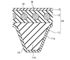
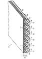
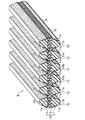
- FIG. 2 is a perspective view of a V-ribbed belt piece according to Embodiment 1.
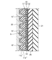
- FIG. 3 is a cross-sectional view of one V-rib of the V-ribbed belt according to Embodiment 1.
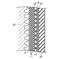
- FIG. It is a longitudinal cross-sectional view of a belt shaping
- FIG. 5 is a first explanatory view of the method for manufacturing the V-ribbed belt according to the first embodiment.
- FIG. 6 is a second explanatory diagram of the method for manufacturing the V-ribbed belt according to the first embodiment.
- FIG. 6 is a third explanatory diagram of the method for manufacturing the V-ribbed belt according to the first embodiment.
- FIG. 10 is a fourth explanatory diagram of the method for manufacturing the V-ribbed belt according to the first embodiment. It is a figure which shows the pulley layout of the auxiliary machine drive belt transmission of a motor vehicle.
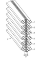
- 6 is a perspective view of a V-ribbed belt piece according to Embodiment 2.
- FIG. 6 is a cross-sectional view of one V-rib of the V-ribbed belt according to Embodiment 2.
- FIG. 6 is a first explanatory view of a method for manufacturing a V-ribbed belt according to Embodiment 2.
- FIG. 10 is a second explanatory diagram of the method for manufacturing the V-ribbed belt according to the second embodiment.
- 6 is a perspective view of a V-ribbed belt piece according to Embodiment 3.
- FIG. 6A is a first explanatory diagram of a method for manufacturing a V-ribbed belt according to a third embodiment.
- FIG. 10 is a second explanatory diagram of the method for manufacturing the V-ribbed belt according to the third embodiment.
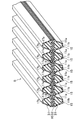
- 6 is a perspective view of a V-ribbed belt piece according to Embodiment 4.
- FIG. It is sectional drawing for one V rib of the V ribbed belt which concerns on Embodiment 4.
- FIG. It is a 1st explanatory view of the manufacturing method of the V ribbed belt concerning Embodiment 4.
- FIG. 10B is a second explanatory diagram of the method for manufacturing the V-ribbed belt according to the fourth embodiment.
- FIG. 10 is a third explanatory diagram of the method for manufacturing the V-ribbed belt according to the fourth embodiment. It is a perspective view of the double-sided V-ribbed belt piece according to another embodiment corresponding to the first embodiment. It is a perspective view of a double-sided V-ribbed belt piece according to another embodiment corresponding to the second embodiment. It is a perspective view of the double-sided V-ribbed belt piece according to another embodiment corresponding to the third embodiment. It is a perspective view of the double-sided V-ribbed belt piece according to another embodiment corresponding to the fourth embodiment. It is a perspective view of the low edge type V belt piece concerning other embodiments.
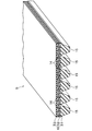
- the V-ribbed belt B according to the first embodiment is, for example, an endless belt used for an auxiliary machine driving belt transmission provided in an engine room of an automobile.
- the V-ribbed belt B according to the first embodiment has a belt length of 700 mm to 3000 mm, a belt width of 10 mm to 36 mm, and a belt thickness of 4.0 mm to 5.0 mm.
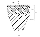
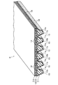
- the V-ribbed belt B is formed of a triple layer including a compression rubber layer 11 that constitutes a pulley contact portion on the belt inner peripheral side, an intermediate adhesive rubber layer 12, and a back rubber layer 13 on the belt outer peripheral side.
- a ribbed belt body 10 is provided.
- a core wire 14 is embedded in an intermediate portion in the thickness direction of the adhesive rubber layer 12 of the V-ribbed belt body 10 so as to form a spiral having a pitch in the belt width direction.
- the thickness of the compressed rubber layer 11 is, for example, 1.0 mm to 3.6 mm
- the thickness of the adhesive rubber layer 12 is, for example, 1.0 mm to 2.5 mm
- the thickness of the back rubber layer 13 is, for example, 0. It is 4 mm or more and 0.8 mm or less.
- a configuration in which a back reinforcing cloth is provided instead of the back rubber layer 13 may be used.
- the compression rubber layer 11 is provided so that a plurality of V ribs 15 hang down to the inner peripheral side of the belt.
- the plurality of V ribs 15 are each formed in a ridge having a substantially inverted triangular cross section extending in the belt length direction, and arranged in parallel in the belt width direction.
- Each V-rib 15 has, for example, a rib height of 2.0 mm to 3.0 mm and a width between proximal ends of 1.0 mm to 3.6 mm.
- the number of V ribs is, for example, 3 or more and 6 or less (6 in FIG. 1).
- the compressed rubber layer 11 is formed of a rubber composition in which a rubber component is crosslinked by heating and pressing an uncrosslinked rubber composition in which various compounding agents including crosslinked polyolefin particles are blended with a rubber component. ing. Accordingly, the rubber composition forming the compressed rubber layer 11 contains a crosslinked rubber component and various compounding agents including crosslinked polyolefin particles dispersed in the rubber component. According to the V-ribbed belt B according to the first embodiment, the compressed rubber layer 11 constituting the pulley contact portion is formed of a rubber composition containing crosslinked polyolefin particles. As shown, dramatically higher wear resistance can be obtained. In the following, crosslinked polyolefin particles are referred to as “crosslinked polyolefin particles”, and uncrosslinked polyolefin particles are referred to as “uncrosslinked polyolefin particles”.
- Examples of the rubber component of the rubber composition forming the compressed rubber layer 11 include ethylene-propylene-diene terpolymer (hereinafter referred to as “EPDM”), ethylene-propylene copolymer (EPM), ethylene-butene copolymer (EDM), Examples include ethylene- ⁇ -olefin elastomers such as ethylene-octene copolymer (EOM); chloroprene rubber (CR); chlorosulfonated polyethylene rubber (CSM); hydrogenated acrylonitrile rubber (H-NBR).
- the rubber component is preferably a blend of one or more of these, preferably an ethylene- ⁇ -olefin elastomer, and more preferably EPDM.
- polyolefin constituting the crosslinked polyolefin particles examples include homopolymers such as polyethylene, polypropylene, poly-1-butene and poly-4-methyl-1-pentene; ethylene and propylene, 1-butene, 1-hexene, 1- And copolymers with ⁇ -olefins such as octene and 4-methyl-1-pentene. Of these, it is preferable to use one or two or more kinds of crosslinked polyolefin particles, and it is more preferable to use polyethylene homopolymer particles.
- the cross-linked polyolefin particles preferably include cross-linked polyethylene particles, more preferably include cross-linked polyethylene particles as a main component, and further preferably include only cross-linked polyethylene particles.
- Crosslinked polyolefin particles are obtained by crosslinking ultrahigh molecular weight polyolefin particles having an average molecular weight (weight average molecular weight, number average molecular weight) of 500,000 or more from the viewpoint of enhancing the wear resistance of the compressed rubber layer 11 constituting the pulley contact portion. It is preferable to contain mainly crosslinked ultra-high molecular weight polyolefin particles having an average molecular weight of 500,000 or more, and only crosslinked ultra-high molecular weight polyolefin particles having an average molecular weight of 500,000 or more are crosslinked. More preferably, it is configured.
- the average molecular weight (weight average molecular weight, number average molecular weight) of the ultrahigh molecular weight polyolefin particles is preferably 1,000,000 or more, more preferably 1.8 million or more, still more preferably 2,000,000 or more. Therefore, it is preferably 6 million or less, more preferably 3.5 million or less, and still more preferably 3 million or less.
- Examples of the ultra high molecular weight polyolefin particles include ultra high molecular weight polyethylene particles.
- the average particle diameter of the crosslinked polyolefin particles is preferably 10 ⁇ m or more, more preferably 100 ⁇ m or more from the viewpoint of improving the wear resistance of the compressed rubber layer 11 constituting the pulley contact portion, and also a viewpoint of improving the bending fatigue resistance. Therefore, it is preferably 200 ⁇ m or less, more preferably 170 ⁇ m or less, and still more preferably 150 ⁇ m or less.
- This average particle diameter is obtained by arithmetically averaging 50 to 100 particle diameters (maximum outer diameter) actually measured in consideration of the magnification from a photograph taken with a scanning electron microscope of the crosslinked polyolefin particles.
- the particle size distribution of the crosslinked polyolefin particles is preferably 70% by mass or more, more preferably those having a particle size in the range of 100 ⁇ m or more and 150 ⁇ m or less, from the viewpoint of improving the wear resistance of the compressed rubber layer 11 constituting the pulley contact portion. It is 80 mass% or more, More preferably, it is 90 mass% or more.
- the shape of the crosslinked polyolefin particles is preferably close to a sphere from the viewpoint of increasing the wear resistance of the compressed rubber layer 11 constituting the pulley contact portion, and the aspect ratio obtained by dividing the maximum outer diameter of the crosslinked polyolefin particles by the minimum outer diameter is , Preferably 2.00 or less, more preferably 1.50 or less, still more preferably 1.30 or less.
- This aspect ratio is obtained by arithmetically averaging a value obtained by dividing a maximum outer diameter of 50 or more and 100 or less measured by taking a magnification into consideration from an observation photograph of a cross-linked polyolefin particle with a scanning electron microscope and taking the magnification into consideration. It is done.
- the form before blending is such that spherical particles having a particle size of 10 ⁇ m or more and 50 ⁇ m or less are aggregated in a tuft shape
- the crosslinked polyolefin particles are fused and integrated by heating during production. It is preferably formed in a spherical or elliptical shape.
- the intrinsic viscosity [ ⁇ ] measured in decalin at 135 ° C. of the crosslinked polyolefin particles is preferably 5 dl / g or more from the viewpoint of enhancing the wear resistance of the compressed rubber layer 11 constituting the pulley contact portion. From the viewpoint of enhancing the bending fatigue property, it is preferably 50 dl / g or less, more preferably 30 dl / g or less.
- the melting point of the crosslinked polyolefin particles is preferably 125 ° C. or higher, more preferably 130 ° C. or higher, and preferably 145 ° C. or lower from the viewpoint of improving the wear resistance of the compressed rubber layer 11 constituting the pulley contact portion. .
- This melting point is determined by differential scanning calorimetry (DSC).
- the content of the crosslinked polyolefin particles in the rubber composition forming the compressed rubber layer 11 is preferably 20 with respect to 100 parts by mass of the rubber component from the viewpoint of enhancing the wear resistance of the compressed rubber layer 11 constituting the pulley contact portion. It is preferably at least 50 parts by mass, more preferably at least 50 parts by mass, and even more preferably at least 70 parts by mass. From the viewpoint of enhancing resistance to bending fatigue, it is preferably at most 100 parts by mass, more preferably at most 90 parts by mass.
- the crosslinked polyolefin particles can be prepared by irradiating the uncrosslinked polyolefin particles with radiation.
- the uncrosslinked polyolefin particles are irradiated with radiation, the molecular chains of the polyolefin are broken and crosslinked, and as a result, the molecular chains are bonded at the crosslinking points.
- crosslinking proceeds in order outward from the center of the particle.
- radiation include ⁇ -rays, ⁇ -rays, ⁇ -rays, electron beams, ions, and the like, and electron beams or ⁇ -rays are preferably used.
- the irradiation dose of radiation is preferably 50 kGy or more, more preferably 100 kGy or more, and preferably 700 kGy or less, more preferably 500 kGy or less.
- the crosslinked polyolefin particles preferably include hollow crosslinked polyolefin particles having a hollow portion inside. Since the cross-linked polyolefin particles dispersed in the compressed rubber layer 11 constituting the pulley contact portion include the hollow cross-linked polyolefin particles, it is possible to suppress a decrease in power transmission capability due to slip at the time of being wet. This is because the drainage effect by the hollow part of the hollow crosslinked polyolefin particles exposed on the surface of the compressed rubber layer 11 constituting the pulley contact part and the driving effect by the edge of the hollow part engaging the pulley are obtained. Conceivable.
- the content of the hollow crosslinked polyolefin particles in the crosslinked polyolefin particles is preferably larger than the content of the solid crosslinked polyolefin particles that are solid inside.
- Such solid crosslinked polyolefin particles can be obtained by irradiating uncrosslinked polyolefin particles with a sufficiently large radiation dose.
- the rubber composition forming the compressed rubber layer 11 may further contain uncrosslinked polyolefin particles that are not crosslinked in addition to the crosslinked polyolefin particles.
- the total content of the crosslinked polyolefin particles and the uncrosslinked polyolefin particles in the rubber composition forming the compressed rubber layer 11 is a rubber component from the viewpoint of enhancing the wear resistance of the compressed rubber layer 11 constituting the pulley contact portion.
- it is 20 parts by mass or more, more preferably 50 parts by mass or more, further preferably 70 parts by mass or more, and from the viewpoint of enhancing the bending fatigue resistance, preferably 100 parts by mass or less, relative to 100 parts by mass. More preferably, it is 90 mass parts or less.
- the content of the crosslinked polyolefin particles in the rubber composition forming the compressed rubber layer 11 is preferably larger than the content of the uncrosslinked polyolefin particles.
- the uncrosslinked polyolefin particles may include hollow uncrosslinked polyolefin particles having a hollow portion inside.
- the content of hollow uncrosslinked polyolefin particles in the uncrosslinked polyolefin particles is preferably less than the content of solid uncrosslinked polyolefin particles that are solid inside, and all of the uncrosslinked polyolefin particles are solid uncrosslinked polyolefin particles. It is more preferable that
- the compounding agent examples include a reinforcing material such as carbon black, a filler, a processing aid, a vulcanization aid, a crosslinking agent, and a co-crosslinking agent.
- a reinforcing material for example, carbon black, channel black; furnace black such as SAF, ISAF, N-339, HAF, N-351, MAF, FEF, SRF, GPF, ECF, N-234; FT, MT, etc. Thermal black; acetylene black and the like.
- Silica is also mentioned as the reinforcing material. It is preferable to use one or more of these reinforcing materials.
- the content of the reinforcing material is preferably 30 parts by mass or more and 60 parts by mass or less with respect to 100 parts by mass of the rubber component.
- the filler examples include calcium carbonate and layered silicate. It is preferable to use one or both of the fillers.
- the content of the filler is preferably 10 parts by mass or more and 60 parts by mass or less with respect to 100 parts by mass of the rubber component.
- Examples of the layered silicate of the filler include a smectite group, a vermulite group, and a kaolin group.
- Examples of the smectite group include montmorillonite, beidellite, saponite, and hectorite.
- Examples of the vermulite family include 3 octahedral vermulites, 2 octahedral vermulites, and the like.
- Examples of the kaolin family include kaolinite, dickite, halloysite, lizardite, amesite, and chrysotile. It is preferable to use 1 type, or 2 or more types of these for layered silicate.
- the content of the layered silicate in the rubber composition forming the compressed rubber layer 11 is preferably 10 parts by mass or more and 50 parts by mass or less with respect to 100 parts by mass of the rubber component.
- processing aids include stearic acid, polyethylene wax, and fatty acid metal salts. It is preferable to use one or more of these processing aids.
- the content of the processing aid in the rubber composition forming the compressed rubber layer 11 is preferably 0.1 parts by mass or more and 3 parts by mass or less with respect to 100 parts by mass of the rubber component.
- vulcanization aid examples include metal oxides such as zinc oxide (zinc white) and magnesium oxide. It is preferable to use one or more of these vulcanization aids.
- the content of the vulcanization aid is, for example, 1 part by mass or more and 10 parts by mass or less with respect to 100 parts by mass of the rubber component.
- crosslinking agent examples include organic peroxides and sulfur.
- the cross-linking agent may be either an organic oxide alone, sulfur alone, or a combination of both.
- the compounding amount of the crosslinking agent is, for example, 0.5 parts by mass or more and 8 parts by mass or less with respect to 100 parts by mass of the rubber component. For example, it is 0.5 to 4 parts by mass.
- co-crosslinking agent examples include trimethylolpropane trimethacrylate, ethylene glycol dimethacrylate, triallyl isocyanurate, liquid polybutadiene, N, N′-m-phenylenebismaleimide and the like. It is preferable to use one or more of these co-crosslinking agents.
- the content of the co-crosslinking agent in the rubber composition forming the compressed rubber layer 11 is preferably 0.5 parts by mass or more and 7 parts by mass or less with respect to 100 parts by mass of the rubber component.
- the rubber composition forming the compressed rubber layer 11 may contain short fibers as long as the effect of improving wear resistance is not impaired, but it is preferable that the rubber composition does not substantially contain short fibers.
- the adhesive rubber layer 12 is configured in a band shape having a horizontally long cross section.
- the back rubber layer 13 is also formed in a band shape having a horizontally long cross section.
- the surface of the back rubber layer 13 is preferably formed in a form in which the texture of the woven fabric is transferred from the viewpoint of suppressing sound generated between the flat rubber and the contacting flat pulley.
- Each of the adhesive rubber layer 12 and the back rubber layer 13 is formed of a rubber composition obtained by crosslinking an uncrosslinked rubber composition in which various compounding agents are blended and kneaded with a rubber component and heated and pressurized to be crosslinked with the crosslinking agent. ing. Accordingly, each of the adhesive rubber layer 12 and the back rubber layer 13 contains a crosslinked rubber component and various compounding agents.
- the back rubber layer 13 is preferably formed of a rubber composition that is slightly harder than the adhesive rubber layer 12 from the viewpoint of suppressing the occurrence of adhesion due to contact with the flat pulley.
- Examples of the rubber component of the rubber composition forming the adhesive rubber layer 12 and the back rubber layer 13 include ethylene- ⁇ -olefin elastomer, chloroprene rubber (CR), chlorosulfonated polyethylene rubber (CSM), hydrogenated acrylonitrile rubber ( H-NBR), and the like, but the same rubber component as that of the compressed rubber layer 11 is preferable.
- the compounding agent examples include reinforcing materials such as carbon black, fillers, processing aids, vulcanization aids, crosslinking agents, co-crosslinking agents, and the like, as in the case of the compressed rubber layer 11.
- the compressed rubber layer 11, the adhesive rubber layer 12, and the back rubber layer 13 may be formed of the same rubber composition or may be formed of different rubber compositions.
- the core wire 14 is composed of twisted yarns such as polyester fiber (PET), polyethylene naphthalate fiber (PEN), aramid fiber, vinylon fiber and the like.
- the diameter of the core wire 14 is, for example, 0.50 mm or more and 2.5 mm or less, and the dimension between the centers of the adjacent core wires 14 in the cross section is, for example, 0.050 mm or more and 0.20 mm or less.
- the core wire 14 is dried after being dipped in an adhesive treatment and / or rubber paste that is heated after being immersed in an RFL aqueous solution before molding to give adhesion to the adhesive rubber layer 12 of the V-ribbed belt body 10. Bonding treatment is applied.
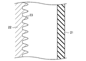
- a belt forming die 20 having a cylindrical inner die 21 and an outer die 22 provided concentrically is used.
- the inner mold 21 is formed of a flexible material such as rubber.
- the outer mold 22 is made of a rigid material such as metal.
- the inner peripheral surface of the outer mold 22 is formed as a molding surface, and V rib forming grooves 23 are provided on the inner peripheral surface of the outer mold 22 at a constant pitch in the axial direction.
- the outer mold 22 is provided with a temperature control mechanism that controls the temperature by circulating a heat medium such as water vapor or a coolant such as water.
- the belt mold 20 is provided with a pressurizing means for pressurizing and expanding the inner mold 21 from the inside.
- each compounding agent is blended in the rubber component and kneaded by a kneader such as a kneader or a Banbury mixer, and the resulting uncrosslinked rubber composition is formed into a sheet by calendar molding or the like.
- a kneader such as a kneader or a Banbury mixer
- the resulting uncrosslinked rubber composition is formed into a sheet by calendar molding or the like.
- a kneader such as a kneader or a Banbury mixer
- solid crosslinked polyolefin particles can be obtained by irradiating uncrosslinked polyolefin particles with a sufficiently large amount of radiation.
- the crosslinked polyolefin particles before blending may have a form in which spherical particles having a particle diameter of 10 ⁇ m or more and 50 ⁇ m or less are aggregated in a tuft shape.
- uncrosslinked rubber sheets 12 'and 13' for the adhesive rubber layer and the back rubber layer are also produced.
- the adhesion process which immerses and heats the strand 14 'for core wires in RFL aqueous solution the adhesion process which immerses in rubber paste and heat-drys is performed.
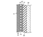
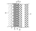
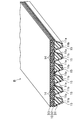
- a rubber sleeve 25 is placed on a cylindrical drum 24 having a smooth surface, and an uncrosslinked rubber sheet 13 ′ for the back rubber layer and an uncrosslinked rubber sheet for the adhesive rubber layer are placed thereon. 12 ′ are wound in order and laminated, and then a strand 14 ′ for a core wire is spirally wound around the cylindrical inner mold 21, and further, an uncrosslinked rubber sheet 12 ′ for an adhesive rubber layer is further formed thereon. And uncrosslinked rubber sheet 11 'for compression rubber layers is wound in order, and uncrosslinked slab S' is formed. At this time, the uncrosslinked rubber sheets 11 ′, 12 ′, and 13 ′ are wound so that the row direction is the belt length direction (circumferential direction).
- the rubber sleeve 25 provided with the uncrosslinked slab S ' is removed from the cylindrical drum 24, and it is set in an internally fitted state on the inner peripheral surface side of the outer mold 22 as shown in FIG.
- the inner mold 21 is positioned and sealed in the rubber sleeve 25 set on the outer mold 22.
- the outer mold 22 is heated, and high-pressure air or the like is injected into the sealed interior of the inner mold 21 to pressurize it.
- the inner mold 21 expands, and the uncrosslinked rubber sheets 11 ′, 12 ′, and 13 ′ for forming the belt of the uncrosslinked slab S ′ are compressed on the molding surface of the outer mold 22.
- the cross-linking of these rubber components proceeds to be integrated and combined with the twisted yarn 14 ′, and finally, a cylindrical belt slab S is formed.
- Cross-linked polyolefin particles are in the form of a spherical shape when the particles before blending are spherical particles having a particle diameter of 10 ⁇ m or more and 50 ⁇ m or less aggregated in a tuft shape by fusing and integrating these spherical particles by heating. Thru
- the molding temperature of the belt slab S is, for example, 100 ° C. or more and 180 ° C. or less
- the molding pressure is, for example, 0.5 MPa or more and 2.0 MPa or less
- the molding time is, for example, 10 minutes or more and 60 minutes or less.
- the inside of the inner mold 21 is decompressed to release the seal, the belt slab S molded between the inner mold 21 and the outer mold 22 is taken out via the rubber sleeve 25, and the belt slab S is cut into a predetermined width.
- the V-ribbed belt B is obtained by turning the front and back. If necessary, the outer peripheral side of the belt slab S, that is, the surface on the V rib 15 side may be polished.
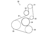
- FIG. 9 shows a pulley layout of the auxiliary drive belt transmission device 30 for an automobile using the V-ribbed belt B according to the first embodiment.
- This accessory drive belt transmission device 30 is of a serpentine drive type in which a V-ribbed belt B is wound around six pulleys, four rib pulleys and two flat pulleys, to transmit power.
- the auxiliary drive belt transmission device 30 is provided with a power steering pulley 31 of a rib pulley at the uppermost position, and an AC generator pulley 32 of a rib pulley is provided below the power steering pulley 31.
- a flat pulley tensioner pulley 33 is provided at the lower left of the power steering pulley 31, and a flat pulley water pump pulley 34 is provided below the tensioner pulley 33.
- a ribshaft crankshaft pulley 35 is provided on the lower left side of the tensioner pulley 33, and a rib pulley air conditioner pulley 36 is provided on the lower right side of the crankshaft pulley 35.
- These pulleys are made of, for example, a metal stamped product, a resin molded product such as a casting, nylon resin, or phenol resin, and have a pulley diameter of ⁇ 50 mm or more and ⁇ 150 mm or less.
- the V-ribbed belt B is wound around the power steering pulley 31 so that the V-rib 15 side contacts, and then wound around the tensioner pulley 33 so that the back side of the belt contacts. Further, the crankshaft pulley 35 and the air conditioner pulley 36 are wound around in order so that the V rib 15 side comes into contact, and further, they are wound around the water pump pulley 34 so that the back side of the belt comes into contact, and the V rib 15 side comes into contact. Is wound around an AC generator pulley 32 and finally returned to the power steering pulley 31.
- the belt span length which is the length of the V-ribbed belt B spanned between the pulleys, is, for example, not less than 50 mm and not more than 300 mm. Misalignment that may occur between the pulleys is 0 ° or more and 2 ° or less.
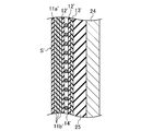
- Embodiment 2 10 and 11 show a V-ribbed belt B according to the second embodiment.
- the part of the same name as Embodiment 1 is shown using the same code
- the compression rubber layer 11 includes a surface rubber layer 11a and a core rubber portion 11b covered with the surface rubber layer 11a.
- the surface rubber layer 11a is provided in layers so as to extend along the entire surface of the V-rib 15, and constitutes a pulley contact portion on the belt inner peripheral side.
- the thickness of the surface rubber layer 11a is, for example, not less than 50 ⁇ m and not more than 500 ⁇ m.
- the core rubber portion 11b is provided inside the surface rubber layer 11a and constitutes a portion other than the surface rubber layer 11a in the compressed rubber layer 11.
- the surface rubber layer 11a is formed of a rubber composition containing a crosslinked rubber component and various compounding agents including crosslinked polyolefin particles dispersed in the rubber component. .
- the core rubber part 11b is formed of a rubber composition containing a crosslinked rubber component and various compounding agents.
- the rubber composition forming the core rubber part 11b may contain crosslinked polyolefin particles, and the content thereof relative to 100 parts by mass of the rubber component is the rubber component of the crosslinked polyolefin particles in the rubber composition forming the surface rubber part 11a.
- the content is preferably less than 100 parts by mass.
- the rubber composition forming the core rubber portion 11b does not substantially contain crosslinked polyolefin particles. Specifically, the rubber composition with respect to 100 parts by mass of the rubber component.
- the content is preferably 10 parts by mass or less, more preferably 5 parts by mass or less, still more preferably 2 parts by mass or less, and most preferably 0 parts by mass.
- the rubber composition which forms the core rubber part 11b may contain uncrosslinked polyolefin particles, it is preferable not to contain substantially uncrosslinked polyolefin particles like the crosslinked polyolefin particles.
- the rubber composition forming the core rubber portion 11b may be the same as the rubber composition forming the adhesive rubber layer 12 or the back rubber layer 13.
- the surface rubber layer 11a of the compressed rubber layer 11 constituting the pulley contact portion is formed of a rubber composition containing crosslinked polyolefin particles.
- the content of the crosslinked polyolefin particles is less in the core rubber portion 11b than in the surface rubber portion 11a, the occurrence of cracks starting from the crosslinked polyolefin particles in the core rubber portion 11b is suppressed, so that bending fatigue resistance is improved. Can be increased.
- uncrosslinked rubber sheets 11a 'and 11b' for the surface rubber layer and the core rubber portion of the compressed rubber layer 11 are produced.
- Crosslinked polyolefin particles are blended in the uncrosslinked rubber sheet 11a 'for the surface rubber layer.
- the uncrosslinked rubber sheet 13 ′ for the back rubber layer and the adhesive rubber are formed on the rubber sleeve 25 covered on the cylindrical drum 24 having a smooth surface as shown in FIG.
- the uncrosslinked rubber sheet 12 ′ for the layers is wound in order and laminated, and the twisted wire 14 ′ for the core wire is spirally wound around the cylindrical inner mold 21 from above, and the adhesive rubber layer is further wound thereon.
- the uncrosslinked rubber sheet 12 ′, the uncrosslinked rubber sheet 11b ′ for the core rubber portion in the compressed rubber layer 11, and the uncrosslinked rubber sheet 11a ′ for the surface rubber layer are wound in order to form an uncrosslinked slab S ′. Then, a cylindrical belt slab S as shown in FIG. 13 is formed by the uncrosslinked slab S ′.
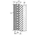
- Embodiment 3 shows a V-ribbed belt B according to the third embodiment.
- the part of the same name as Embodiment 1 is shown using the same code
- FIG. 1 shows a V-ribbed belt B according to the third embodiment.
- the compressed rubber layer 11 includes a surface rubber layer 11a and a core rubber portion 11b covered with the surface rubber layer 11a.
- the surface rubber layer 11a is formed of porous rubber, and is provided in layers so as to extend along the entire surface of the V-rib 15, and constitutes a pulley contact portion on the belt inner peripheral side.
- the thickness of the surface rubber layer 11a is, for example, not less than 50 ⁇ m and not more than 500 ⁇ m.
- the core rubber portion 11b is made of solid rubber, is provided inside the surface rubber layer 11a, and constitutes a portion of the compressed rubber layer 11 other than the surface rubber layer 11a.
- the “porous rubber” in the present application means a crosslinked rubber composition having a number of hollow portions inside and a number of recessed holes 16 on the surface, and the hollow portions and the recessed holes 16 are dispersed. And a structure in which the hollow portion and the recessed hole 16 communicate with each other are included.
- the “solid rubber” in the present application means a crosslinked rubber composition that does not include a hollow portion other than the “porous rubber” and the concave hole 16.
- the surface rubber layer 11a is formed of a rubber composition containing a crosslinked rubber component and various compounding agents including crosslinked polyolefin particles dispersed in the rubber component.
- the surface rubber layer 11a is a porous rubber, unexpanded hollow particles and / or a foaming agent for constituting the porous rubber are blended in the uncrosslinked rubber composition before the formation.
- the unexpanded hollow particles include particles in which a solvent is enclosed in a shell formed of a thermoplastic polymer (for example, acrylonitrile-based polymer).
- the hollow particles may be used alone or in combination of two or more.
- the compounding amount of the hollow particles is preferably 0.5 parts by mass or more and 10 parts by mass or less with respect to 100 parts by mass of the rubber component.
- the foaming agent for example, an ADCA foaming agent containing azodicarbonamide as a main component, a DPT foaming agent containing dinitrosopentamethylenetetramine as a main component, and p, p′-oxybisbenzenesulfonylhydrazide as a main component.
- Examples thereof include organic foaming agents such as OBSH foaming agents and HDCA foaming agents mainly composed of hydrazodicarbonamide. It is preferable to use 1 type, or 2 or more types of these as a foaming agent.
- the blending amount of the foaming agent is preferably 0.5 parts by mass or more and 10 parts by mass or less with respect to 100 parts by mass of the rubber component.
- the surface rubber layer 11a is a porous rubber, a large number of concave holes 16 are formed on the surface thereof.
- the average hole diameter of the concave holes 16 is preferably 10 ⁇ m or more and 150 ⁇ m or less.
- the average hole diameter of the concave holes 16 is determined by a number average of 50 or more and 100 or less measured by the surface image.
- the core rubber part 11b is formed of a rubber composition containing a crosslinked rubber component and various compounding agents.
- the rubber composition forming the core rubber part 11b may contain crosslinked polyolefin particles, and the content thereof relative to 100 parts by mass of the rubber component is the rubber component of the crosslinked polyolefin particles in the rubber composition forming the surface rubber part 11a.
- the content is preferably less than 100 parts by mass.
- the rubber composition forming the core rubber portion 11b does not substantially contain crosslinked polyolefin particles. Specifically, the rubber composition with respect to 100 parts by mass of the rubber component.
- the content is preferably 10 parts by mass or less, more preferably 5 parts by mass or less, still more preferably 2 parts by mass or less, and most preferably 0 parts by mass.
- the rubber composition which forms the core rubber part 11b may contain uncrosslinked polyolefin particles, it is preferable not to contain substantially uncrosslinked polyolefin particles like the crosslinked polyolefin particles.
- the rubber composition that forms the core rubber portion 11 b may be the same as the rubber composition that forms the surface rubber layer 11 a excluding the hollow portion and the recessed hole 16. Further, the rubber composition forming the core rubber portion 11b may be the same as the rubber composition forming the adhesive rubber layer 12 or the back rubber layer 13.
- the rubber composition forming the core rubber portion 11b may be the same as the rubber composition forming the adhesive rubber layer 12 or the back rubber layer 13.
- the surface rubber layer 11a of the compressed rubber layer 11 constituting the pulley contact portion is formed of a rubber composition containing crosslinked polyolefin particles.
- the content of the crosslinked polyolefin particles is less in the core rubber portion 11b than in the surface rubber portion 11a, the occurrence of cracks starting from the crosslinked polyolefin particles in the core rubber portion 11b is suppressed, so that bending fatigue resistance is improved. Can be increased.
- uncrosslinked rubber sheets 11a 'and 11b' for the surface rubber layer and the core rubber part of the compressed rubber layer 11 are produced.
- hollow particles and / or a foaming agent are blended in the uncrosslinked rubber sheet 11a 'for the surface rubber layer.
- the uncrosslinked rubber sheet 13 ′ for the back rubber layer and the adhesive rubber are formed on the rubber sleeve 25 covered on the cylindrical drum 24 having a smooth surface by the same method as in the first embodiment.
- the uncrosslinked rubber sheet 12 ′ for the layers is wound in order and laminated, and the twisted wire 14 ′ for the core wire is spirally wound around the cylindrical inner mold 21 from above, and the adhesive rubber layer is further wound thereon.
- the uncrosslinked rubber sheet 12 ′, the uncrosslinked rubber sheet 11b ′ for the core rubber portion in the compressed rubber layer 11, and the uncrosslinked rubber sheet 11a ′ for the surface rubber layer are wound in order to form an uncrosslinked slab S ′.
- a cylindrical belt slab S as shown in FIG. 17 is formed from the uncrosslinked slab S ′.
- Embodiment 4 shows a V-ribbed belt B according to the fourth embodiment.
- the part of the same name as Embodiment 1 and 3 is shown using the same code
- FIG. 4 shows a V-ribbed belt B according to the fourth embodiment.
- the compression rubber layer 11 includes a surface rubber layer 11a and a core rubber portion 11b partially covered with the surface rubber layer 11a.
- the surface rubber layer 11a is formed of porous rubber and is provided along the outer side surface portion of each of the V ribs 15 on both sides, and the opposite side surface portions of the pair of V ribs 15 adjacent to each other and It is provided along the bottom of the rib to be connected, and constitutes a pulley contact portion on the belt inner peripheral side.
- the latter surface rubber layer 11a has an inverted U-shaped cross section.
- each surface rubber layer 11a is provided so as to include an outer side surface portion of each of the V ribs 15 on both sides, or an opposing side surface portion of a pair of V ribs 15 adjacent to each other.
- the thickness of the surface rubber layer 11a is, for example, not less than 50 ⁇ m and not more than 500 ⁇ m.
- the core rubber portion 11b is made of solid rubber, is provided inside the surface rubber layer 11a, and constitutes a portion of the compressed rubber layer 11 other than the surface rubber layer 11a.
- a cylindrical belt slab S as shown in FIG. 20 is molded by the same method as in the third embodiment.
- a protrusion 15 ' having a substantially trapezoidal cross section extending in the circumferential direction is formed so as to be continuous in the axial direction, and the surface layer thereof is formed of the porous rubber 11a "and the others.
- the inside is formed of solid rubber 11b ′′.
- the ground grinding wheel 27 is brought into contact with rotation, and the belt slab S is also rotated between the pair of slab spanning shafts 26.
- a plurality of V ribs 15 are formed by grinding the protrusions on the outer periphery of the belt slab S, and in the plurality of V ribs 15, the surface rubber layer 11 a of porous rubber and A solid rubber core rubber portion 11b is formed.
- the V-ribbed belt B is shown.
- the present invention is not particularly limited to this, and is similar to the compression rubber layer 11 in addition to the compression rubber layer 11 on the belt inner peripheral side as shown in FIG. 23A. It may be a double-sided V-ribbed belt B having a stretched rubber layer 17 constituting a pulley contact portion on the outer peripheral side of the belt of the structure described above, and in addition to the compressed rubber layer 11 on the inner peripheral side of the belt as shown in FIGS.
- a double-sided V-ribbed belt B having a stretch rubber layer 17 composed of a surface rubber layer 17a and a core rubber portion 17b constituting a pulley contact portion on the belt outer periphery side having a structure similar to that of the rubber layer 11 may be used.
- the V-ribbed belt B is shown.
- the present invention is not particularly limited to this, and the low-edge type V-belt B having the compression rubber layer 11 constituting the pulley contact portion on the belt inner peripheral side is used.
- a stretched rubber layer 17 constituting a pulley contact portion on the belt outer peripheral side having the same configuration as the compressed rubber layer 11 is provided. It may be a low-edge double-sided V-belt B.
- the V-ribbed belt B is shown.
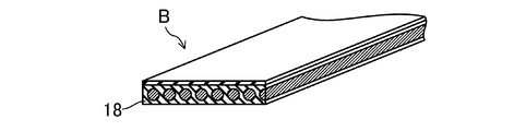
- the present invention is not particularly limited to this, and a flat belt having an inner rubber layer 18 constituting a pulley contact portion on the belt inner peripheral side as shown in FIG. Belt B may be used.
- Example 1 V-ribbed belt
- Example 1-1 V-ribbed belt having the same configuration as that of the second embodiment in the following Example 1-1 and Comparative example 1-1 was manufactured. Each configuration is also shown in Table 1.
- EPDM as a rubber component is put into a chamber of a closed Banbury mixer and masticated. Next, 100 parts by mass of this rubber component, 2 parts by mass of carbon black, 40 parts by mass of silica, 5 parts by mass of calcium carbonate, 80 parts by mass of ultrahigh molecular weight polyethylene particles, 40 parts by mass of layered silicate (bentonite), 2.7 parts by mass of hollow particles, 0.5 parts by mass of stearic acid, 5 parts by mass of zinc oxide, and an organic peroxide having a purity of 40% by mass V in which 8 parts by mass (3.2 parts by mass) of a crosslinking agent and 2 parts by mass of a co-crosslinking agent were added and kneaded, and a surface rubber layer of a compression rubber layer was formed using the obtained uncrosslinked rubber composition.
- a ribbed belt was produced and designated as Example 1-1.
- the ultra-high molecular weight polyethylene particles a product name: Hi-Z Million 240S (average molecular weight: 2 million, average particle size: 120 ⁇ m) manufactured by Mitsui Chemicals Co., Ltd., subjected to a crosslinking treatment by electron beam irradiation was used. Accordingly, the ultrahigh molecular weight polyethylene particles after the treatment include crosslinked ultrahigh molecular weight polyethylene particles.
- the core rubber portion of the compressed rubber layer, the adhesive rubber layer, and the back rubber layer were formed of another rubber composition containing EPDM as a rubber component.
- the core wire was composed of a twisted yarn made of polyethylene terephthalate fiber.
- the belt peripheral length was 900 mm, the belt width was 10.68 mm, the belt thickness was 4.3 mm, and the number of ribs was three.
- Comparative Example 1-1 Surface rubber of the compressed rubber layer using an uncrosslinked rubber composition obtained in the same manner as in Example 1-1 except that uncrosslinked uncrosslinked particles were used as ultrahigh molecular weight polyethylene particles. A V-ribbed belt having a layer formed thereon was prepared, and this was designated as Comparative Example 1-1.
- FIG. 26 shows a pulley layout of the belt running test machine 40 for evaluating wear resistance.
- the belt running test machine 40 for wear resistance evaluation includes a drive pulley 41, which is a rib pulley having a pulley diameter of 60 mm, a first driven pulley 42, which is a rib pulley having a pulley diameter of 60 mm, and a vertical direction thereof. And a second driven pulley 43 that is a rib pulley having a pulley diameter of 55 mm provided on the right side in the middle.
- the surface roughness (Ra) of the driving pulley 41 and the first driven pulley 42 was 2 ⁇ 0.3 ⁇ m.
- the surface roughness (Ra) of the second driven pulley was 0.3 ⁇ m.
- the V-rib side is the drive pulley 41
- the first The second driven pulley 43 is wound around in contact with the driven pulley 42 and the second driven pulley 43 to apply a rotational load of 2.62 kW to the first driven pulley 42 and to the second driven pulley 43 so that the belt tension is applied.
- a dead weight DW of 157 N was loaded, and the belt was run by rotating the drive pulley 41 at a rotational speed of 4900 rpm at room temperature.
- Example 1-1 after 19 hours have elapsed from the start of belt travel, 44 hours have elapsed, and 67 hours have elapsed, belt travel is temporarily stopped, and V-ribbed belt B is removed from belt travel tester 40 for wear resistance evaluation. The belt mass was measured, and the abrasion rate was determined by dividing the abrasion mass obtained by subtracting the belt mass from the initial belt mass by the initial belt mass. In addition, the wear rate during the belt running time from 44 hours to 67 hours was determined. For Comparative Example 1-1, after 24 hours have elapsed from the start of belt travel, 44 hours have elapsed, and 70 hours have elapsed, belt travel is temporarily stopped, and V-ribbed belt B is removed from belt travel tester 40 for wear resistance evaluation. The belt mass was measured, and the abrasion rate was determined by dividing the abrasion mass obtained by subtracting the belt mass from the initial belt mass by the initial belt mass. In addition, the wear rate during the belt running time from 44 hours to 70 hours was obtained.
- FIG. 27 shows the relationship between the running time of the belt running and the wear rate in Example 1-1 and Comparative Example 1-1.
- FIGS. 28A and 28B show the form of the surface of the V-rib of the pulley contact portion after running the belt in Example 1-1 and Comparative Example 1-1, respectively.
- Example 1-1 the wear rate, which is the progress of the wear rate per unit time during the belt running time from 44 hours to 67 hours, is 48 ppm / h.
- Comparative Example 1-1 the wear rate is approximately 464 ppm / h in the belt running time corresponding to the period from 44 hours to 70 hours. This is because the wear rate of Example 1-1 is 9 times or less of the wear rate of Comparative Example 1-1, that is, the wear resistance life of Example 1-1 is 9 times or more that of Comparative Example 1-1. This represents a dramatic improvement in wear resistance.
- the ultrahigh molecular weight polyethylene particles used in any of Example 1-1 and Comparative Example 1-1 had a shape before blending in which spherical particles were aggregated in a tuft shape, but according to FIGS. It can be seen that the spherical particles are fused and integrated to form a sphere or ellipsoid.
- Example 2 V-ribbed belt
- Examples 2-1 to 2-3 and Comparative Examples 2-1 to 2-3 below were produced. Each configuration is also shown in Table 2.
- EPDM as a rubber component is put into a chamber of a closed Banbury mixer and masticated. Then, 2 parts by mass of ISAF carbon black and ultrahigh molecular weight polyethylene particles are irradiated with an electron beam with respect to 100 parts by mass of the rubber component. 80 parts by mass of the hollow cross-linked polyethylene particles (1) subjected to the cross-linking treatment, 40 parts by mass of silica, 40 parts by mass of layered silicate (bentonite), 5 parts by mass of calcium carbonate, 2.7 parts by mass of hollow particles, and 0.
- a V-ribbed belt having the same configuration as that of the third embodiment in which the surface rubber layer of the compression rubber layer was formed using the uncrosslinked rubber composition was produced, and this was taken as Example 2-1.
- hollow cross-linked polyethylene particles (1) a product name: Hi-Zex Million 240S (average molecular weight: 2 million, average particle size: 120 ⁇ m) manufactured by Mitsui Chemicals, Ltd. is irradiated with an electron beam at an irradiation dose of 200 kGy to perform cross-linking treatment. The thing in which the hollow part was formed was used.
- the core rubber portion of the compressed rubber layer, the adhesive rubber layer, and the back rubber layer were formed of another rubber composition containing EPDM as a rubber component.
- the core wire was composed of a twisted yarn made of polyethylene terephthalate fiber. Further, the surface rubber layer of the compressed rubber layer was subjected to surface polishing.
- the belt length was 900 mm
- the belt width was 21.36 mm
- the belt thickness was 4.3 mm
- the number of ribs was six.
- Example 2-2 In place of the crosslinked hollow polyethylene particles (1), trade name: Sunfine UH-850 (average molecular weight: 2,200,000, average particle size: 150 ⁇ m) manufactured by Asahi Kasei Chemicals Co., Ltd. is irradiated with an electron beam at an irradiation dose of 200 kGy.
- a V-ribbed belt having the same configuration as that of Example 2-1 was produced except that the crosslinked hollow polyethylene particles (2) in which the hollow portion was formed by applying the above were used, and this was designated as Example 2-2.
- Example 2-3 A V-ribbed belt having the same configuration as that of Example 2-1 except that HAF carbon black is used instead of ISAF carbon black and no hollow particles are used, and the same configuration as that of the above-described Embodiment 2 is manufactured, and then it is carried out. It was set as Example 2-3.
- Comparative Example 2-2 A V-ribbed belt having the same structure as Comparative Example 2-1 was prepared except that 70 parts by mass of solid uncrosslinked polyethylene particles were used with respect to 100 parts by mass of the rubber component and no foaming agent was used. -2.
- Comparative Example 2-3 Except for using 100 parts by mass of solid uncrosslinked polyethylene particles with respect to 100 parts by mass of rubber component and 3.1 parts by mass of hollow particles with respect to 100 parts by mass of rubber component, the same configuration as Comparative Example 2-2 was used. A V-ribbed belt was produced and used as Comparative Example 2-3.
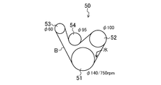
- FIG. 29 shows a pulley layout of the belt running test machine 50.
- This belt running test machine 50 is provided with a drive pulley 51 which is a zinc-plated rib pulley having a pulley diameter of 140 mm at the lowest position, and a first driven pulley 52 (air conditioner) which is a rib pulley having a pulley diameter of 100 mm diagonally upward to the right.
- a second driven pulley 53 (alternator pulley), which is a rib pulley having a pulley diameter of 60 mm, is provided obliquely above and to the left of the drive pulley 51 and the first driven pulley 52, and further, the first driven pulley 52 is provided.
- An idler pulley 54 which is a flat pulley having a pulley diameter of 95 mm, is provided on the left side.
- the V rib side of the V-ribbed belt B contacts the drive pulley 51, which is a rib pulley, and the first and second driven pulleys 52, 53, and the back side contacts the idler pulley 54, which is a flat pulley. Then, it is configured to be wound around.
- the idler pulley 54 is wound around each pulley of the belt running test machine 50 so that a belt tension of 400 N is applied.
- a load (first driven pulley 52: 1.5 MPa, second driven pulley 53: 20A) is applied to the first and second driven pulleys 52, 53, and the driving pulley 51 is set to 750 ⁇ under an ambient temperature of 25 ° C.
- the belt was run at a rotation speed of 120 rpm. And 10 ml of water was dripped at the belt winding start part of the drive pulley 51, and the presence or absence of the stop of belt running by slip was confirmed.
- Table 2 shows the test results. According to Table 2, in Examples 2-1 to 2-3 in which the hollow cross-linked polyethylene particles were dispersed and exposed on the surface of the pulley contact portion, the belt running did not stop, but the surface of the pulley contact portion was not solid. In Comparative Examples 2-1 to 2-3 in which the crosslinked polyethylene particles were dispersed and exposed, the belt running stopped. From this, it can be seen that Examples 2-1 to 2-3 in which the hollow cross-linked polyethylene particles are dispersed and exposed on the surface of the pulley contact portion have a high effect of suppressing a decrease in power transmission capability due to slippage when wet. .
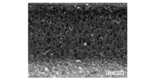
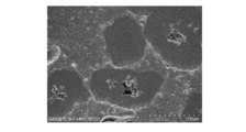
- FIGS. 30A and 30B are photographs taken by a scanning electron microscope showing the form of the surface of the V-rib of the pulley contact portion after running the belt in Example 2-2 and Comparative Example 2-3, respectively.
- Example 2-2 it is recognized that the particles exposed on the surface of the pulley contact portion have hollow portions, whereas in Comparative Example 2-3, the surface of the pulley contact portion is observed. No hollow portions are observed in the exposed particles. Therefore, in Examples 2-1 to 2-3, the drainage effect by the hollow portion of the hollow crosslinked polyethylene particles exposed on the surface of the pulley contact portion and the driving effect by the engagement of the edge of the hollow portion with the pulley are obtained. It is thought that it is obtained.
- the present invention is useful in the technical field of friction transmission belts and manufacturing methods thereof.
Landscapes
- Engineering & Computer Science (AREA)
- General Engineering & Computer Science (AREA)
- Mechanical Engineering (AREA)
- Chemical & Material Sciences (AREA)
- Textile Engineering (AREA)
- Health & Medical Sciences (AREA)
- Chemical Kinetics & Catalysis (AREA)
- Medicinal Chemistry (AREA)
- Polymers & Plastics (AREA)
- Organic Chemistry (AREA)
- Compositions Of Macromolecular Compounds (AREA)
Abstract
Description
図1及び2は、実施形態1に係るVリブドベルトB(摩擦伝動ベルト)を示す。実施形態1に係るVリブドベルトBは、例えば、自動車のエンジンルーム内に設けられる補機駆動用のベルト伝動装置等に用いられるエンドレスのものである。実施形態1に係るVリブドベルトBは、例えば、ベルト長さが700mm以上3000mm以下、ベルト幅が10mm以上36mm以下、及びベルト厚さが4.0mm以上5.0mm以下である。
図10及び11は、実施形態2に係るVリブドベルトBを示す。なお、実施形態1と同一名称の部分は、実施形態1と同一符号を用いて示す。
図14及び15は、実施形態3に係るVリブドベルトBを示す。なお、実施形態1と同一名称の部分は、実施形態1と同一符号を用いて示す。
図18及び19は、実施形態4に係るVリブドベルトBを示す。なお、実施形態1及び3と同一名称の部分は、実施形態1及び3と同一符号を用いて示す。
上記実施形態1~4では、VリブドベルトBを示したが、特にこれに限定されるものではなく、図23A示すようなベルト内周側の圧縮ゴム層11に加えて、圧縮ゴム層11と同様の構造のベルト外周側のプーリ接触部分を構成する伸張ゴム層17を有する両面VリブドベルトBであってもよく、図23B~D示すようなベルト内周側の圧縮ゴム層11に加えて、圧縮ゴム層11と同様の構造のベルト外周側のプーリ接触部分を構成する表面ゴム層17a及びコアゴム部17bからなる伸張ゴム層17を有する両面VリブドベルトBであってもよい。
(Vリブドベルト)
以下の実施例1-1及び比較例1-1の上記実施形態2と同様の構成のVリブドベルトを作製した。なお、それぞれの構成については表1にも示す。
密閉式のバンバリーミキサーのチャンバーにゴム成分としてのEPDMを投入して素練りし、次いで、このゴム成分100質量部に対して、カーボンブラック2質量部、シリカ40質量部、炭酸カルシウム5質量部、超高分子量ポリエチレン粒子80質量部、層状珪酸塩(ベントナイト)40質量部、中空粒子2.7質量部、ステアリン酸0.5質量部、酸化亜鉛5質量部、純度40質量%の有機過酸化物架橋剤8質量部(3.2質量部)、及び共架橋剤2質量部を投入配合して混練し、得られた未架橋ゴム組成物を用いて圧縮ゴム層の表面ゴム層を形成したVリブドベルトを作製し、それを実施例1-1とした。
超高分子量ポリエチレン粒子として、架橋処理を施していない未架橋のものを用いたことを除いて実施例1-1と同様にして得られた未架橋ゴム組成物を用いて圧縮ゴム層の表面ゴム層を形成したVリブドベルトを作製し、それを比較例1-1とした。

図26は、耐摩耗性評価用ベルト走行試験機40のプーリレイアウトを示す。
図27は、実施例1-1及び比較例1-1のベルト走行の走行時間と摩耗率との関係を示す。また、図28A及びBは、それぞれ実施例1-1及び比較例1-1のベルト走行後のプーリ接触部分のVリブの表面の形態を示す。
(Vリブドベルト)
以下の実施例2-1~2-3及び比較例2-1~2-3のVリブドベルトを作製した。なお、それぞれの構成については表2にも示す。
密閉式のバンバリーミキサーのチャンバーにゴム成分としてのEPDMを投入して素練りし、次いで、このゴム成分100質量部に対して、ISAFカーボンブラック2質量部、超高分子量ポリエチレン粒子に電子線の照射による架橋処理を施した中空架橋ポリエチレン粒子(1)80質量部、シリカ40質量部、層状珪酸塩(ベントナイト)40質量部、炭酸カルシウム5質量部、中空粒子2.7質量部、ステアリン酸0.5質量部、酸化亜鉛5質量部、純度40質量%の有機過酸化物架橋剤8質量部(3.2質量部)、及び共架橋剤2質量部を投入配合して混練し、得られた未架橋ゴム組成物を用いて圧縮ゴム層の表面ゴム層を形成した上記実施形態3と同様の構成のVリブドベルトを作製し、それを実施例2-1とした。
架橋中空ポリエチレン粒子(1)の代わりに、旭化成ケミカルズ社製の商品名:サンファインUH-850(平均分子量:220万、平均粒子径:150μm)に電子線を照射線量200kGyで照射して架橋処理を施すことにより中空部が形成された架橋中空ポリエチレン粒子(2)を用いたことを除いて実施例2-1と同一構成のVリブドベルトを作製し、それを実施例2-2とした。
ISAFカーボンブラックの代わりにHAFカーボンブラックを用い且つ中空粒子を用いていないことを除いて実施例2-1と同一構成で且つ上記実施形態2と同様の構成のVリブドベルトを作製し、それを実施例2-3とした。
中空架橋ポリエチレン粒子(1)の代わりに、電子線の照射による架橋処理を施していない三井化学社製の商品名:ハイゼックスミリオン240S、つまり、中実未架橋ポリエチレン粒子をゴム成分100質量部に対して50質量部用い且つ中空粒子をゴム成分100質量部に対して2.6質量部及び発泡剤をゴム成分100質量部に対して7.3質量部用いたことを除いて実施例2-1と同一構成のVリブドベルトを作製し、それを比較例2-1とした。
中実未架橋ポリエチレン粒子をゴム成分100質量部に対して70質量部用い且つ発泡剤を用いていないことを除いて比較例2-1と同一構成のVリブドベルトを作製し、それを比較例2-2とした。
中実未架橋ポリエチレン粒子をゴム成分100質量部に対して100質量部及び中空粒子をゴム成分100質量部に対して3.1質量部用いたことを除いて比較例2-2と同一構成のVリブドベルトを作製し、それを比較例2-3とした。

図29はベルト走行試験機50のプーリレイアウトを示す。
表2に試験結果を示す。表2によれば、プーリ接触部分の表面に中空架橋ポリエチレン粒子が分散して露出した実施例2-1~2-3ではベルト走行は停止しなかったが、プーリ接触部分の表面に中実未架橋ポリエチレン粒子が分散して露出した比較例2-1~2-3ではベルト走行が停止した。このことから、プーリ接触部分の表面に中空架橋ポリエチレン粒子が分散して露出した実施例2-1~2-3は、被水時におけるスリップによる動力伝達能力の低下を抑える効果が高いことが分かる。
11 圧縮ゴム層
11a,17a 表面ゴム層
11b,17b コアゴム部
17 伸張ゴム層
18 内側ゴム層
Claims (12)
- プーリ接触部分を構成するゴム層を有する摩擦伝動ベルトであって、
前記ゴム層は、架橋したゴム成分と、架橋したポリオレフィン粒子と、を含有するゴム組成物で形成されている摩擦伝動ベルト。 - 請求項1に記載された摩擦伝動ベルトにおいて、
前記架橋したポリオレフィン粒子が、平均分子量が50万以上の超高分子量ポリオレフィン粒子を架橋したものを含む摩擦伝動ベルト。 - 請求項1又は2に記載された摩擦伝動ベルトにおいて、
前記架橋したポリオレフィン粒子が架橋したポリエチレン粒子を含む摩擦伝動ベルト。 - 請求項1乃至3のいずれかに記載された摩擦伝動ベルトにおいて、
前記架橋したポリオレフィン粒子が、中空部を有する中空の架橋したポリオレフィン粒子を含む摩擦伝動ベルト。 - 請求項1乃至4のいずれかに記載された摩擦伝動ベルトにおいて、
前記ゴム組成物における前記架橋したポリオレフィン粒子の含有量が前記ゴム成分100質量部に対して20質量部以上100質量部以下である摩擦伝動ベルト。 - 請求項1乃至5のいずれかに記載された摩擦伝動ベルトにおいて、
前記ゴム組成物が更に未架橋のポリオレフィン粒子を含有する摩擦伝動ベルト。 - 請求項1乃至6のいずれかに記載された摩擦伝動ベルトにおいて、
前記ゴム層で被覆されたコアゴム部を更に有する摩擦伝動ベルト。 - 請求項7に記載された摩擦伝動ベルトにおいて、
前記コアゴム部は、前記架橋したポリオレフィン粒子のゴム成分100質量部に対する含有量が前記ゴム層よりも少ないゴム組成物、又は、前記架橋したポリオレフィン粒子を含有しないゴム組成物で形成されている摩擦伝動ベルト。 - 請求項1乃至8のいずれかに記載された摩擦伝動ベルトにおいて、
前記ゴム層が多孔ゴムである摩擦伝動ベルト。 - プーリ接触部分を構成するゴム層を有する摩擦伝動ベルトの製造方法であって、
前記ゴム層を、ゴム成分に架橋したポリオレフィン粒子を配合した未架橋ゴム組成物を加熱及び加圧して前記ゴム成分を架橋させたゴム組成物で形成する摩擦伝動ベルトの製造方法。 - 請求項10に記載された摩擦伝動ベルトの製造方法において、
前記架橋したポリオレフィン粒子を、未架橋のポリオレフィン粒子に放射線を照射して調製する摩擦伝動ベルトの製造方法。 - 請求項10又は11に記載された摩擦伝動ベルトの製造方法において、
前記架橋したポリオレフィン粒子は、配合前の形態が、球状粒子が房状に凝集したものであり、前記球状粒子が前記加熱により融着して一体化することにより球体状乃至楕円体状に形成される摩擦伝動ベルトの製造方法。
Priority Applications (4)
| Application Number | Priority Date | Filing Date | Title |
|---|---|---|---|
| CN201780006466.4A CN108496024B (zh) | 2016-01-22 | 2017-01-05 | 摩擦传动带及其制造方法 |
| KR1020187021926A KR102515424B1 (ko) | 2016-01-22 | 2017-01-05 | 마찰 전동 벨트 및 그 제조방법 |
| DE112017000461.6T DE112017000461T5 (de) | 2016-01-22 | 2017-01-05 | Reibungstransmissionsriemen und Herstellungsverfahren |
| US16/041,616 US10647075B2 (en) | 2016-01-22 | 2018-07-20 | Friction transmission belt and manufacturing method therefor |
Applications Claiming Priority (4)
| Application Number | Priority Date | Filing Date | Title |
|---|---|---|---|
| JP2016-011033 | 2016-01-22 | ||
| JP2016011033A JP6348133B2 (ja) | 2016-01-22 | 2016-01-22 | 摩擦伝動ベルト及びその製造方法 |
| JP2016-059188 | 2016-03-23 | ||
| JP2016059188A JP6348136B2 (ja) | 2016-03-23 | 2016-03-23 | 摩擦伝動ベルト及びその製造方法 |
Related Child Applications (1)
| Application Number | Title | Priority Date | Filing Date |
|---|---|---|---|
| US16/041,616 Continuation US10647075B2 (en) | 2016-01-22 | 2018-07-20 | Friction transmission belt and manufacturing method therefor |
Publications (1)
| Publication Number | Publication Date |
|---|---|
| WO2017126324A1 true WO2017126324A1 (ja) | 2017-07-27 |
Family
ID=59361541
Family Applications (1)
| Application Number | Title | Priority Date | Filing Date |
|---|---|---|---|
| PCT/JP2017/000130 WO2017126324A1 (ja) | 2016-01-22 | 2017-01-05 | 摩擦伝動ベルト及びその製造方法 |
Country Status (5)
| Country | Link |
|---|---|
| US (1) | US10647075B2 (ja) |
| KR (1) | KR102515424B1 (ja) |
| CN (1) | CN108496024B (ja) |
| DE (1) | DE112017000461T5 (ja) |
| WO (1) | WO2017126324A1 (ja) |
Cited By (1)
| Publication number | Priority date | Publication date | Assignee | Title |
|---|---|---|---|---|
| JP2020132702A (ja) * | 2019-02-15 | 2020-08-31 | 三井化学株式会社 | ゴム組成物およびゴム成形体の製造方法 |
Families Citing this family (5)
| Publication number | Priority date | Publication date | Assignee | Title |
|---|---|---|---|---|
| JP6616793B2 (ja) * | 2016-04-15 | 2019-12-04 | 三ツ星ベルト株式会社 | 摩擦伝動ベルト |
| CN110770470B (zh) * | 2017-06-19 | 2021-04-06 | 阪东化学株式会社 | 传动带 |
| WO2019017101A1 (ja) * | 2017-07-19 | 2019-01-24 | バンドー化学株式会社 | 伝動ベルト及びその製造方法 |
| CN109573461A (zh) * | 2018-12-27 | 2019-04-05 | 阿雷法(苏州)汽车部件有限公司 | 一种双面四槽带 |
| JP7323560B2 (ja) * | 2021-01-29 | 2023-08-08 | バンドー化学株式会社 | 摩擦伝動ベルト |
Citations (5)
| Publication number | Priority date | Publication date | Assignee | Title |
|---|---|---|---|---|
| JPS63277255A (ja) * | 1987-05-09 | 1988-11-15 | Dainippon Ink & Chem Inc | 光架橋性ポリオレフィン樹脂組成物 |
| JP2007170587A (ja) * | 2005-12-26 | 2007-07-05 | Mitsuboshi Belting Ltd | Vリブドベルト |
| JP2007255635A (ja) * | 2006-03-24 | 2007-10-04 | Mitsuboshi Belting Ltd | 摩擦伝動ベルト |
| JP2011102641A (ja) * | 2006-07-14 | 2011-05-26 | Bando Chemical Industries Ltd | 摩擦伝動ベルト及びその製造方法 |
| JP2013113343A (ja) * | 2011-11-25 | 2013-06-10 | Mitsuboshi Belting Ltd | 摩擦伝動ベルト及びその製造方法 |
Family Cites Families (10)
| Publication number | Priority date | Publication date | Assignee | Title |
|---|---|---|---|---|
| JP3657389B2 (ja) | 1996-05-16 | 2005-06-08 | 株式会社ブリヂストン | ゴム組成物 |
| US6028143A (en) | 1996-05-16 | 2000-02-22 | Bridgestone Corporation | Rubber composition containing cross linkable polyethylene |
| CN1197907C (zh) * | 1999-03-16 | 2005-04-20 | 三井化学株式会社 | 可交联的橡胶组合物及其应用 |
| US7413785B2 (en) * | 2003-08-07 | 2008-08-19 | Tyco Electronics Corporation | Heat-recoverable foam tubing |
| JP2005155682A (ja) * | 2003-11-20 | 2005-06-16 | Bando Chem Ind Ltd | 伝動ベルト帆布用処理液、伝動ベルト用帆布及び伝動ベルト |
| JP2007070592A (ja) | 2004-11-25 | 2007-03-22 | Mitsuboshi Belting Ltd | ゴム組成物、ゴム組成物の製造方法及び摩擦伝動ベルト |
| JP2007170454A (ja) | 2005-12-20 | 2007-07-05 | Mitsuboshi Belting Ltd | Vリブドベルト |
| FR2898171B1 (fr) | 2006-03-03 | 2009-02-27 | Hutchinson Sa | Courroie de transmission de puissance. |
| JP2007270917A (ja) | 2006-03-30 | 2007-10-18 | Mitsuboshi Belting Ltd | 摩擦伝動ベルト |
| CN103168184B (zh) * | 2010-10-21 | 2015-08-05 | 阪东化学株式会社 | 摩擦传动带 |
-
2017
- 2017-01-05 CN CN201780006466.4A patent/CN108496024B/zh active Active
- 2017-01-05 KR KR1020187021926A patent/KR102515424B1/ko active IP Right Grant
- 2017-01-05 DE DE112017000461.6T patent/DE112017000461T5/de active Pending
- 2017-01-05 WO PCT/JP2017/000130 patent/WO2017126324A1/ja active Application Filing
-
2018
- 2018-07-20 US US16/041,616 patent/US10647075B2/en active Active
Patent Citations (5)
| Publication number | Priority date | Publication date | Assignee | Title |
|---|---|---|---|---|
| JPS63277255A (ja) * | 1987-05-09 | 1988-11-15 | Dainippon Ink & Chem Inc | 光架橋性ポリオレフィン樹脂組成物 |
| JP2007170587A (ja) * | 2005-12-26 | 2007-07-05 | Mitsuboshi Belting Ltd | Vリブドベルト |
| JP2007255635A (ja) * | 2006-03-24 | 2007-10-04 | Mitsuboshi Belting Ltd | 摩擦伝動ベルト |
| JP2011102641A (ja) * | 2006-07-14 | 2011-05-26 | Bando Chemical Industries Ltd | 摩擦伝動ベルト及びその製造方法 |
| JP2013113343A (ja) * | 2011-11-25 | 2013-06-10 | Mitsuboshi Belting Ltd | 摩擦伝動ベルト及びその製造方法 |
Cited By (2)
| Publication number | Priority date | Publication date | Assignee | Title |
|---|---|---|---|---|
| JP2020132702A (ja) * | 2019-02-15 | 2020-08-31 | 三井化学株式会社 | ゴム組成物およびゴム成形体の製造方法 |
| JP7257176B2 (ja) | 2019-02-15 | 2023-04-13 | 三井化学株式会社 | ゴム組成物およびゴム成形体の製造方法 |
Also Published As
| Publication number | Publication date |
|---|---|
| US10647075B2 (en) | 2020-05-12 |
| US20180326680A1 (en) | 2018-11-15 |
| CN108496024B (zh) | 2020-07-28 |
| DE112017000461T5 (de) | 2018-10-04 |
| CN108496024A (zh) | 2018-09-04 |
| KR20180104636A (ko) | 2018-09-21 |
| KR102515424B1 (ko) | 2023-03-29 |
Similar Documents
| Publication | Publication Date | Title |
|---|---|---|
| WO2017126324A1 (ja) | 摩擦伝動ベルト及びその製造方法 | |
| JP6306266B2 (ja) | 摩擦伝動ベルト | |
| JP4768893B2 (ja) | 摩擦伝動ベルト | |
| JP5829614B2 (ja) | 摩擦伝動ベルト | |
| JP5508648B2 (ja) | Vリブドベルト及びその製造方法 | |
| JP5586282B2 (ja) | 摩擦伝動ベルト及びその製造方法、並びにそれを用いたベルト伝動装置 | |
| WO2017094213A1 (ja) | Vリブドベルト | |
| JP6306267B2 (ja) | 摩擦伝動ベルト | |
| JP6348136B2 (ja) | 摩擦伝動ベルト及びその製造方法 | |
| JP6348133B2 (ja) | 摩擦伝動ベルト及びその製造方法 | |
| JP7209773B2 (ja) | 摩擦伝動ベルト | |
| JP6227843B1 (ja) | 伝動ベルト | |
| JP6007353B2 (ja) | Vリブドベルト及びその製造方法、並びにベルト伝動装置 | |
| JP6078702B1 (ja) | Vリブドベルト | |
| JP2017106518A (ja) | 摩擦伝動ベルト | |
| JP6903791B2 (ja) | 摩擦伝動ベルト | |
| JP6581892B2 (ja) | 摩擦伝動ベルト | |
| JP2019007596A (ja) | 摩擦伝動ベルト及びその製造方法 |
Legal Events
| Date | Code | Title | Description |
|---|---|---|---|
| 121 | Ep: the epo has been informed by wipo that ep was designated in this application |
Ref document number: 17741204 Country of ref document: EP Kind code of ref document: A1 |
|
| WWE | Wipo information: entry into national phase |
Ref document number: 112017000461 Country of ref document: DE |
|
| ENP | Entry into the national phase |
Ref document number: 20187021926 Country of ref document: KR Kind code of ref document: A |
|
| 122 | Ep: pct application non-entry in european phase |
Ref document number: 17741204 Country of ref document: EP Kind code of ref document: A1 |