WO2017104528A1 - セラミック体の製造方法及びそれに用いる分散体 - Google Patents
セラミック体の製造方法及びそれに用いる分散体 Download PDFInfo
- Publication number
- WO2017104528A1 WO2017104528A1 PCT/JP2016/086521 JP2016086521W WO2017104528A1 WO 2017104528 A1 WO2017104528 A1 WO 2017104528A1 JP 2016086521 W JP2016086521 W JP 2016086521W WO 2017104528 A1 WO2017104528 A1 WO 2017104528A1
- Authority
- WO
- WIPO (PCT)
- Prior art keywords
- group
- dispersion
- ceramic body
- solvent
- ceramic
- Prior art date
- Legal status (The legal status is an assumption and is not a legal conclusion. Google has not performed a legal analysis and makes no representation as to the accuracy of the status listed.)
- Ceased
Links
- 0 CC(C)(*)OCC(*)C(C)(C)ON Chemical compound CC(C)(*)OCC(*)C(C)(C)ON 0.000 description 1
Classifications
-
- B—PERFORMING OPERATIONS; TRANSPORTING
- B33—ADDITIVE MANUFACTURING TECHNOLOGY
- B33Y—ADDITIVE MANUFACTURING, i.e. MANUFACTURING OF THREE-DIMENSIONAL [3D] OBJECTS BY ADDITIVE DEPOSITION, ADDITIVE AGGLOMERATION OR ADDITIVE LAYERING, e.g. BY 3D PRINTING, STEREOLITHOGRAPHY OR SELECTIVE LASER SINTERING
- B33Y70/00—Materials specially adapted for additive manufacturing
-
- B—PERFORMING OPERATIONS; TRANSPORTING
- B28—WORKING CEMENT, CLAY, OR STONE
- B28B—SHAPING CLAY OR OTHER CERAMIC COMPOSITIONS; SHAPING SLAG; SHAPING MIXTURES CONTAINING CEMENTITIOUS MATERIAL, e.g. PLASTER
- B28B1/00—Producing shaped prefabricated articles from the material
- B28B1/30—Producing shaped prefabricated articles from the material by applying the material on to a core or other moulding surface to form a layer thereon
-
- B—PERFORMING OPERATIONS; TRANSPORTING
- B33—ADDITIVE MANUFACTURING TECHNOLOGY
- B33Y—ADDITIVE MANUFACTURING, i.e. MANUFACTURING OF THREE-DIMENSIONAL [3D] OBJECTS BY ADDITIVE DEPOSITION, ADDITIVE AGGLOMERATION OR ADDITIVE LAYERING, e.g. BY 3D PRINTING, STEREOLITHOGRAPHY OR SELECTIVE LASER SINTERING
- B33Y10/00—Processes of additive manufacturing
-
- C—CHEMISTRY; METALLURGY
- C04—CEMENTS; CONCRETE; ARTIFICIAL STONE; CERAMICS; REFRACTORIES
- C04B—LIME, MAGNESIA; SLAG; CEMENTS; COMPOSITIONS THEREOF, e.g. MORTARS, CONCRETE OR LIKE BUILDING MATERIALS; ARTIFICIAL STONE; CERAMICS; REFRACTORIES; TREATMENT OF NATURAL STONE
- C04B35/00—Shaped ceramic products characterised by their composition; Ceramics compositions; Processing powders of inorganic compounds preparatory to the manufacturing of ceramic products
- C04B35/622—Forming processes; Processing powders of inorganic compounds preparatory to the manufacturing of ceramic products
Definitions
- the present invention relates to a method for producing a three-dimensional shaped object (ceramic body), and more particularly to a shape holding method and a dispersion used therefor.
- a technique for maintaining the shape is required.
- a well-known method is generally a method in which a mold is used to inject a thermoplastic resin, molten metal, or the like.
- producing a ceramic body by this method using a ceramic dispersion as a material requires a step of drying a solvent in a mold, which is practically difficult.
- 3D printers are attracting attention as a small-volume production method.
- a solution containing a photocurable resin is ejected from an inkjet head and then cured by an ultraviolet lamp. Since this method can simultaneously supply various materials by increasing the number of nozzles, it is possible to produce a shaped article made of a plurality of materials.
- a photocurable resin is indispensable, and therefore the ceramic concentration in the modeled object has to be reduced accordingly.
- Patent Document 1 a manufacturing process of a three-dimensional ceramic body is proposed by printing a suspension containing a ceramic layer by layer using an inkjet printer, and drying and curing the formed composite layer. Yes.
- a suspension containing 50% to 80% by weight of ceramic particles in a dispersion medium containing an aqueous boehmite sol, a low molecular weight alcohol, a drying inhibitor, and an organic fluidizing agent is used as the ink, and then ejected by inkjet.
- a three-dimensional ceramic body is formed by drying and sintering.
- it is essential to contain an aqueous boehmite sol (alumina monohydrate), and it was impossible to produce a shaped article that does not contain alumina.
- each layer in order to maintain the shape, each layer must be dried at 80 ° C., and it takes a lot of time to produce a three-dimensional structure by stacking multiple layers.
- Patent Document 2 an ink-jet ink capable of forming a thick film having a thickness of 10 ⁇ m is prepared, which contains 0.1 to 20 parts by weight of a semiconductor oxide.
- the oxide particles are cured using a binder.
- the oxide particle concentration is only mentioned up to 20 parts by weight, it is unclear whether it can be carried out at a higher concentration. is there.
- the 10-micrometer-thick thick film is formed, it is unknown whether it can model with the thickness beyond it.
- the problem to be solved by the present invention is to provide a method for producing a high-purity ceramic body, and without requiring a boehmite sol or a binder component and without requiring a drying step, the ceramic body
- An object of the present invention is to provide a high-purity and high-concentration ceramic particle dispersion that can be applied to the production method described above.
- the present inventors have cured ceramic nanoparticles dispersed in a specific solvent using the surface modification group of the particles, thereby allowing a binder such as a resin or the main component of the target ceramic body.
- the present inventors completed the present invention by finding that a high-purity ceramic body that does not contain any other inorganic substance as an essential component can be formed while enclosing a solvent.
- the present invention A solvent (A) having a vapor pressure at 20 ° C. of 1500 Pa or less and having no reactivity with the polymerizable functional group, and ceramic particles modified with an energy ray polymerizable functional group or a thermally polymerizable functional group ( B), a step (I) of supplying a dispersion containing the support to the support layer by layer or at a time, and a step (II) of curing the dispersion supplied to the support by energy rays or heat.
- this invention relates to the manufacturing method of a ceramic sintered compact which has the process of drying or sintering the ceramic body obtained by the said method.
- the present invention also includes a solvent (A) having a vapor pressure at 20 ° C. of not more than 1500 Pa and having no reactivity with the polymerizable functional group, an energy ray polymerizable functional group, or a thermally polymerizable functional group.
- the present invention relates to a modeling dispersion characterized by containing modified ceramic particles (B).
- the dispersion for modeling of the present invention does not require the boehmite sol and the binder component disclosed in Patent Document 1 and Patent Document 2, ceramics are dispersed in a solvent, so that the change in viscosity with respect to temperature is slow. And the temperature stability of the ceramic dispersion is high. Moreover, since the solvent and ceramic fine particles are the main components and the other components are not essential, a high-purity ceramic fine particle dispersion can be prepared. Furthermore, a high-purity ceramic sintered body is produced by removing the solvent by drying or sintering from the ceramic body produced by using this dispersion in the steps in the above-described method for producing a ceramic body of the present invention. be able to.
- the dispersion of the present invention has a ceramic particle size of 200 nm or less, it is possible to produce a ceramic body having a high transparency and a thickness of 1 cm or more by an optical isoenergy ray polymerization reaction. Furthermore, since the dispersion of the present invention can be applied to any kind of ceramic as long as it has particles having a surface-modifying group dispersed in a solvent, it can be used for manufacturing a shaped article using a ceramic having various functions. Applicable.
- the dispersion of the present invention has a solvent (A) having a vapor pressure at 20 ° C. of 1500 Pa or less and no reactivity with the polymerizable functional group, and an energy ray polymerizable functional group or a thermally polymerizable functional group. It is the dispersion for shaping
- the dispersion of the present invention uses the solvent as described above, so that the ceramic particles can easily form a network structure while containing the solvent, and a three-dimensional shape cured product can be more suitably produced.
- the inventors have found such a property, paying attention to this, and manufacturing a ceramic body that is a shaped product (a method for maintaining the shape before removing the organic component) and a ceramic sintered body (drying or firing the organic component).
- a ceramic body that is a shaped product (a method for maintaining the shape before removing the organic component) and a ceramic sintered body (drying or firing the organic component).
- the solvent can remain in the cured product when the dispersion is cured (it can be cured while containing the solvent), so that distortion due to volatilization of the solvent is less likely to occur. Since it is easy to form a network between them, a three-dimensional cured product can be suitably produced.
- the solvent in the cured product preferably remains at 80% by weight or more of the weight of the solvent before curing, from the viewpoint of further reducing the distortion of the network between particles, and remains at 90% by weight or more. More preferably.
- the solvent to be used is preferably a solvent having a vapor pressure at 20 ° C. of 1500 Pa or less, and more preferably a solvent having a vapor pressure at 20 ° C. of 1000 Pa or less. Within this range, it is possible to more suitably produce a network between particles during curing.
- the solvent (A) may be used as a single component, or two or more of these may be selected and mixed for use.
- the solvent (A) preferably has a low viscosity and high dispersibility of the ceramic particles modified with the polymerizable compound. Accordingly, the solvent (A) preferably has a molecular weight of 500 or less, and more preferably a molecular weight of 300 or less.
- ceramic nanoparticles (B) modified with a desired energy ray polymerizable functional group or heat polymerizable functional group are dispersed in a specific solvent (A) with a particle size of 200 nm or less, and the solvent A method of maintaining a three-dimensional shape of a ceramic body without requiring a step of supplying a layer or a layer onto a support and drying a solvent using a dispersion that can be cured while encapsulating I will provide a.
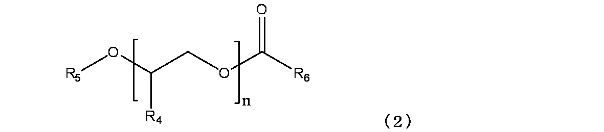
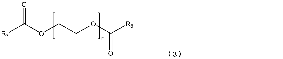
- Examples of the solvent (A) satisfying such requirements include a compound represented by the following formula (1), a compound represented by the following formula (2), a compound represented by the following formula (3), 3-methoxy Butyl acetate, glycerin, 1,3-butylene glycol, 2-ethyl-1,3-hexanediol, 1,3-octylene glycol, 2-ethylbutanol, 2-ethylhexyl acetate, 3-methylbutyl acetate, benzyl acetate, propion Methyl acid, butyl propionate, dibutyl phthalate, methyl lactate, ethyl lactate, butyl lactate, nonane, decane, methyl benzoate, ethyl benzoate, butyl benzoate, N-methyl-2-pyrrolidone, dimethyl sulfoxide, N , N-dimethylformamide, N, N-dimethylacetamide, ⁇ -buty
- R 1 is a hydrogen atom or a methyl group
- R 2 is a hydrogen atom or an optionally branched alkyl group having 1 to 12 carbon atoms
- R 3 is a hydrogen atom, a benzyl group, a phenyl group or a carbon atom.
- It is an optionally branched alkyl group of 1 to 12.
- n is an integer of 1 to 4.
- R 4 is a hydrogen atom or a methyl group
- R 5 is a hydrogen atom, a benzyl group, or an optionally branched alkyl group having 1 to 12 carbon atoms
- R 6 is a methyl group or an ethyl group.
- n is an integer of 1 to 4.
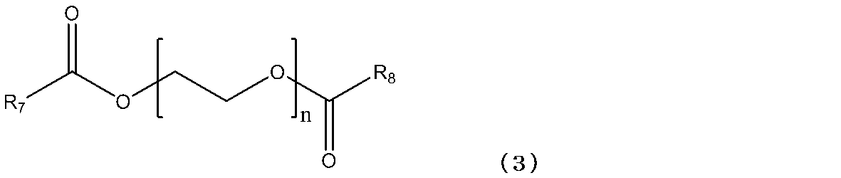
- R 7 and R 8 are each independently a methyl group or an ethyl group. Also, n is an integer of 1 to 4.
- the solvent (A) include a compound represented by the formula (1), a compound represented by the formula (2), a compound represented by the formula (3), N-methyl-2-pyrrolidone, Examples thereof include dimethyl sulfoxide. These may use only 1 type and may mix and use 2 or more types.
- the ceramic particles (B) modified with various polymerizable compounds ( ⁇ ) react with energy rays or thermal stimulation to form a network structure, and the above-described solvent is included. It is thought to cure. Therefore, the higher the crosslink density, the higher the strength of the ceramic body.
- the polymerizable compound ( ⁇ ) that modifies the ceramic particles (B) is not particularly limited as long as it is a substance that can be coordinated and / or bonded to the surface of the ceramic and has a functional group that is polymerized by irradiation with energy rays or heat. .
- a polymerizable compound ( ⁇ ) that can be polymerized by irradiation with energy rays or heat can be used as a single component or a mixture of two or more thereof.
- Examples of the polymerizable compound ( ⁇ ) include organic carboxylic acid compounds, silane compounds, metal coupling agents, epoxy group-containing compounds, hydroxyl group-containing compounds, amino group-containing compounds, and thiol-containing compounds.
- the polymerization reaction may be any one such as radical polymerization, anion polymerization, cation polymerization, and thermal polymerization.
- polymerizable compounds ( ⁇ ) as the polymerizable compound having a functional group that is polymerized by irradiation with energy rays, for example, a polymerizable compound containing a vinyl group is used. Among them, the polymerization rate by irradiation with energy rays is used. (Meth) acrylic compounds and styrenic compounds are preferred.
- Examples of the polymerizable compound having a functional group that is polymerized by irradiation with energy rays include acrylic acid, methacrylic acid, maleic acid, fumaric acid, 2- (meth) acryloyloxyethyl succinic acid, and 2- (meth) acryloyl.
- Roxyethylhexahydrophthalic acid 2- (meth) acryloyloxyethylphthalic acid, vinyltrimethoxysilane, vinyltriethoxysilane, 3- (meth) acryloxypropylmethyldimethoxysilane, 3- (meth) acryloxypropyl Trimethoxysilane, 3- (meth) acryloxypropyltriethoxysilane, N- (2-aminomethyl) -3-aminopropyltrimethoxysilane, p-styryltrimethoxysilane, phenyltrimethoxysilane, 2-hydroxyethyl ( (Meth) acrylate, 2-hydroxypropyl Meth) acrylate, 3-hydroxypropyl (meth) acrylate, 2-hydroxybutyl (meth) acrylate, 4-hydroxybutyl (meth) acrylate.
- examples of the polymerizable compound having a functional group that is polymerized by heat include a polymerizable compound containing an epoxy group in addition to the polymerizable compound containing a vinyl group.
- Examples of polymerizable compounds containing an epoxy group include epichlorohydrin, 2- (3,4-epoxycyclohexyl) ethyltrimethoxysilane, 3-glycidoxypropylmethyldimethoxysilane, 3-glycidoxypropyltri Examples include methoxysilane, 3-glycidoxypropylmethyldiethoxysilane, and 3-glycidoxypropyltriethoxysilane.
- the ceramic particles (B) may have a compound ( ⁇ ) having no polymerizable functional group (hereinafter referred to as a compound) as long as it can be coordinated and / or bonded to the surface of the ceramic. (May be described as ( ⁇ )), and may be further modified.
- the compound ( ⁇ ) is effective for improving the dispersibility of the ceramic particles in the solvent.
- Examples of the compound ( ⁇ ) include acetic acid, valeric acid, hexanoic acid, heptanoic acid, 2-ethylhexanoic acid, octanoic acid, 2-methylheptanoic acid, 4-methyloctanoic acid, nonanoic acid, decanoic acid, neodecane Acid, dodecanoic acid, tetradecanoic acid, hexadecanoic acid, octadecanoic acid, oleic acid, 12-hydroxystearic acid, cyclohexanol, 1-butanol, 2-butanol, oleic alcohol, methylcyclohexanol, ethylene glycol monoethyl ether . These may be used alone or in combination of two or more.
- the method for modifying the surface of the ceramic particles (B) may be a method usually employed for modifying the ceramic particles, and the method is not particularly limited.
- ceramic nanoparticles such as metal oxides are placed in a reaction vessel in a nitrogen atmosphere and stirred while spraying the polymerizable compound ( ⁇ ) or compound ( ⁇ ), and then heated and stirred at 100 to 150 ° C. for 1 hour or longer to modify.
- a dry method or a wet method in which the ceramic particles (B) are slurried, the polymerizable compound ( ⁇ ) and the compound ( ⁇ ) are added, and the mixture is modified by stirring while applying heat may be used.
- surface modification may be performed when the ceramic nanoparticles are synthesized by a sol-gel method or a supercritical hydrothermal synthesis method.
- the dispersion is such that after curing, the solvent (A) remaining in the cured product remains 80% by weight or more, more preferably 90% by weight or more of the weight of the solvent before curing. Can be selected and used. By using such a solvent (A), a three-dimensional ceramic body can be suitably produced.
- the average dispersed particle size of the particles in the dispersion is 5 nm to 200 nm, preferably 5 nm to 100 nm. If it is this range, since dispersion stability can be improved more, it is preferable. In addition, since a dispersion with higher transparency can be produced, it is preferable because, when cured with energy rays, the energy rays can be further transmitted to the inside, and a cured product having a three-dimensional shape can be more suitably produced. .
- the content of the ceramic particles (B) in the dispersion is 5 vol% or more and 70 vol% or less, preferably 5 vol% or more and 60 vol% or less. If it is the said density
- the additive shaping dispersion of the present invention contains ceramic particles.
- the ceramic particles may be single, or a mixture, solid solution or composite oxide of two or more kinds of ceramics.
- Examples of single ceramic SiO 2, Al 2 O 3 , TiO 2, ZrO 2, In 2 O 3, ZnO, SnO 2, La 2 O 3, Y 2 O 3, CeO 2, MgO, Si 3 such as N 4, and examples of solid solution or composite oxide, ITO, ATO, BaTiO 3, CaTiO 3, MgAl 2 O 4, Al 2 O 3 -ZrO 2, Y 2 O 3- ZrO 2, boehmite and / or MgO and / or ZrO 2 stabilized with CaO or the like, Al 2 O 3, Y 2 O 3, HfO 2, CeO 2, Al 2 O 3 -ZrO 2, Al 2 O 3, Y 2 O 3, Fe 2 O 3 and Si 3 N 4 stabilized with other rare earth oxides.
- a dispersion containing ceramic particles (B) modified with a functional group or a thermopolymerizable functional group as an essential component is supplied to the support layer by layer, cured by energy rays or heat, and laminated. Manufacture the body.
- the support in the present invention may be any shape and material as long as it can hold the dispersion before curing, such as a plane support such as a graphite plate, a platinum plate, a metal plate, a ceramic plate, and a glass plate, And a three-dimensional support such as a container made of these materials.
- the supply in the present invention is to bring the dispersion into contact with the support, and to make a new dispersion come into contact with the cured dispersion.
- the production method include a 3D-inkjet method in which a dispersion is supplied onto a support in small amounts and cured by energy rays or heat, and a support is placed in a dispersion filled in a container. Then, by applying light or heat from the outside to cure the dispersion in contact with the support and moving the support up or down, the dispersion is gradually supplied to the support and the cured product and cured. And an optical modeling method for producing a three-dimensional shape.
- a method in which a dispersion is supplied at a time into a mold having a prescribed dimension and cured by energy rays or heat is also possible.
- the mold having the prescribed dimensions include a container such as a petri dish, a mold manufactured with agar, a mold printed with a printer, and the like.
- the thickness of one layer at the time of additive shaping is defined by the thickness through which energy rays are transmitted or heat is transmitted. Since the dispersion of the present invention has a small dispersion particle size of ceramic particles and the transparency of the dispersion is very high, a layer having a thickness of 1 mm ⁇ thickness can be formed at a time by, for example, a photopolymerization reaction. Furthermore, by laminating them, a ceramic body having an arbitrary thickness can be formed. In the production of the three-dimensionally shaped ceramic body of the present invention, since it is cured using the surface modification group of the ceramic particles, the type of ceramic is not limited as long as the particles can be provided with a desired surface modification group.
- a ceramic shaped article having a theoretically intended inorganic component purity of 100% can be produced.
- objects that can be produced according to the present invention, models in the field of education and toys, models imitating animals and plants, various products in the industrial field, operation confirmation and fitting, texture, and size.
- models in the prototype stage for confirmation miniatures in the architectural field such as structural confirmation of the body, preparation of samples, etc., models of organs and bones in the medical field, prosthetic hands, crowns, artificial bones, etc. It is applicable to the production of a simple model.
- Example 1 10 g of methacrylic group-modified silica (Admantech Co., Ltd. Admanano YA010C-SM1 particle size 10 nm) was weighed into a screw tube, 10 g of diethylene glycol ethyl methyl ether (vapor pressure 91 Pa / 20 ° C., molecular weight: 148), and a photopolymerization initiator ( BASF Japan KK IRGACURE 184) 0.3 g was added and stirred to prepare a translucent 50 wt% (30 vol%) dispersion. The average dispersed particle diameter of the silica particles in the obtained dispersion was 15 nm.
- the measuring method and the measuring apparatus used in the present invention are as follows. ⁇ Analysis of average dispersed particle size> Measuring device: Zeta potential / particle size measurement system ELS-Z manufactured by Otsuka Electronics Co., Ltd.
- Example 2 A cylindrical mold made of agar with an outer diameter of 1 cm (inner diameter of 0.5 cm) and a height of 1.5 cm was placed in advance on a petri dish ( ⁇ 4 cm). Into this, 0.1 g of a silica dispersion prepared in the same manner as in Example 1 was poured, and cured by irradiating with 300 mJ / cm 2 ultraviolet rays in the atmosphere. Further, 0.1 g of the silica dispersion was injected thereon and cured twice, and a total of 0.3 g of the silica dispersion was laminated in a cylinder and cured. As a result, a transparent ceramic body having a height of 1.2 cm enclosing a solvent could be produced. The change in weight before and after UV curing was 1.0% (residual solvent amount 99%).
- Example 3 A cylindrical mold made of agar with an outer diameter of 1 cm (inner diameter of 0.5 cm) and a height of 1.5 cm was placed in advance on a petri dish ( ⁇ 4 cm). Into this, 0.3 g of a silica dispersion prepared in the same manner as in Example 1 was injected, and cured by irradiation with ultraviolet rays of 1000 mJ / cm 2 under the atmosphere. As a result, a transparent ceramic body having a height of 1.2 cm enclosing a solvent could be produced. The change in weight before and after UV curing was 0.7% (solvent residual amount of 99% or more).
- Example 4 Methacrylic group-modified silica (Admanex Co., Ltd. Admanano YA010C-SM1 particle size 10 nm) 4 g was weighed into a screw tube, diethylene glycol ethyl methyl ether (vapor pressure 91 Pa / 20 ° C., molecular weight: 148) 16 g, photopolymerization initiator ( BASF Japan KK IRGACURE 184) 0.3 g was added and stirred to prepare a 20% by weight (10 vol%) dispersion of translucent silica. The average dispersed particle diameter of the silica particles in the obtained dispersion was 15 nm. Using the obtained silica dispersion, the same operation as in Example 1 was performed. As a result, a transparent plate-like ceramic body having a thickness of 1 to 2 mm containing a solvent could be produced. The change in weight before and after UV curing was 0.8% (the residual solvent amount was 99% or more).
- Example 5 12 g of methacrylic group-modified silica (Admantech Co., Ltd. Admanano YA010C-SM1 particle size 10 nm) was weighed into a screw tube, and photopolymerized with 8 g of 3-methoxybutyl acetate (vapor pressure 400 Pa / 20 ° C., molecular weight: 146.2). 0.3 g of an initiator (IRGACURE 184, manufactured by BASF Japan Ltd.) was added and stirred to prepare a 60% by weight (39 vol%) dispersion of translucent silica. The average dispersed particle diameter of the silica particles in the obtained dispersion was 16 nm.
- an initiator IRGACURE 184, manufactured by BASF Japan Ltd.
- Example 2 Using the obtained silica dispersion, the same operation as in Example 1 was performed. As a result, a transparent plate-like ceramic body having a thickness of 1 to 2 mm containing a solvent could be produced. The change in weight before and after UV curing was 1.9% (residual solvent amount was 98% or more).
- Example 6 Methacrylic group-modified silica (Admantech Co., Ltd. Admanano YA010C-SM1 particle size 10 nm) 4 g was weighed into a screw tube and 3-methoxybutyl acetate (vapor pressure 400 Pa / 20 ° C., molecular weight 146.2) 16 g and photopolymerization started. 0.3 g of an agent (BASF Japan KK IRGACURE 184) was added and stirred to prepare a 20% by weight (10 vol%) dispersion of translucent silica. The average dispersed particle diameter of the silica particles in the obtained dispersion was 15 nm. Using the obtained silica dispersion, the same operation as in Example 1 was performed. As a result, a transparent plate-like ceramic body having a thickness of 1 to 2 mm containing a solvent could be produced. The change in weight before and after UV curing was 1.8% (solvent residual amount of 98% or more).
- Example 7 Methacrylic group-modified silica (Admantech Co., Ltd. Admanano YA010C-SM1 particle size 10 nm) 12.8 g was weighed into a screw tube and propylene glycol monoethyl ether (vapor pressure 533 Pa / 20 ° C., molecular weight: 140.2) 7.2 g Then, 0.3 g of a photopolymerization initiator (IRGACURE 184, manufactured by BASF Japan Ltd.) was added and stirred to prepare a dispersion of translucent silica 64 wt% (about 42 vol%). The average dispersed particle diameter of the silica particles in the obtained dispersion was 18 nm.
- a photopolymerization initiator IRGACURE 184, manufactured by BASF Japan Ltd.
- Example 8 4 g of methacrylic group-modified silica (Admanex Co., Ltd. Admanano YA010C-SM1 particle size 10 nm) is weighed into a screw tube, and 16 g of propylene glycol monoethyl ether (vapor pressure 533 Pa / 20 ° C., molecular weight: 140.2) is photopolymerized. 0.3 g of initiator (IRGACURE 184, manufactured by BASF Japan Ltd.) was added and stirred to prepare a dispersion of 20% by weight (about 9 vol%) of translucent silica. The average dispersed particle diameter of the silica particles in the obtained dispersion was 17 nm.
- Example 2 Using the obtained silica dispersion, the same operation as in Example 1 was performed. As a result, a transparent plate-like ceramic body having a thickness of 1 to 2 mm containing a solvent could be produced.
- the change in weight before and after UV curing was 5.4% (residual solvent amount 94% or more).
- Example 9 8.4 g of methacrylic group-modified silica (Admantech Co., Ltd. Admanano YA010C-SM1 particle size 10 nm) was weighed into a screw tube and ethylene glycol monomethyl ether (vapor pressure 840 Pa / 20 ° C., molecular weight: 76.1) 11.6 g Then, 0.3 g of a photopolymerization initiator (IRGACURE 184, manufactured by BASF Japan Ltd.) was added and stirred to prepare a dispersion of 42 wt% (about 24 vol%) of translucent silica. The average dispersed particle diameter of the silica particles in the obtained dispersion was 17 nm.
- Example 10 Methacrylic group-modified silica (Admanex Co., Ltd. Admanano YA010C-SM1 particle size 10nm) 4g was weighed into a screw tube and ethylene glycol monomethyl ether (vapor pressure 840Pa / 20 ° C, molecular weight: 76.1) 16g, photopolymerization started 0.3 g of an agent (BASF Japan KK IRGACURE 184) was added and stirred to prepare a 20% by weight (10 vol%) dispersion of translucent silica. The average dispersed particle diameter of the silica particles in the obtained dispersion was 16 nm. Using the obtained silica dispersion, the same operation as in Example 1 was performed. As a result, a transparent plate-like ceramic body having a thickness of 1 to 2 mm containing a solvent could be produced. The change in weight before and after UV curing was 6.7% (the residual solvent amount was 93% or more).
- Example 11 4 g of methacrylic group-modified silica (Admantech Co., Ltd. Admanano YA010C-SM1 particle size 10 nm) was weighed into a screw tube, N-methyl-2-pyrrolidone (vapor pressure 39 Pa / 20 ° C., molecular weight: 99.1) 16 g, A photopolymerization initiator (IRGACURE 184, manufactured by BASF Japan Ltd.) (0.3 g) was added and stirred to prepare a 20% by weight (11 vol%) dispersion of translucent silica. The average dispersed particle diameter of the silica particles in the obtained dispersion was 16 nm.
- Example 2 Using the obtained silica dispersion, the same operation as in Example 1 was performed. As a result, a transparent plate-like ceramic body having a thickness of 1 to 2 mm containing a solvent could be produced.
- the change in weight before and after UV curing was 0.7% (solvent residual amount of 99% or more).
- Example 12 4 g of methacrylic group-modified silica (Admantech Co., Ltd. Admanano YA010C-SM1 particle size 10 nm) was weighed into a screw tube, 16 g of dimethyl sulfoxide (vapor pressure 84 Pa / 20 ° C., molecular weight: 78.1), and a photopolymerization initiator ( BASF Japan KK IRGACURE 184) 0.3 g was added and stirred to prepare a 20% by weight (about 11 vol%) dispersion of translucent silica. The average dispersed particle diameter of the silica particles in the obtained dispersion was 21 nm. Using the obtained silica dispersion, the same operation as in Example 1 was performed. As a result, a transparent plate-like ceramic body having a thickness of 1 to 2 mm containing a solvent could be produced. The change in weight before and after UV curing was 0.8% (the residual solvent amount was 99% or more).
- Example 13 4 g of the epoxy group-modified silica synthesized in Synthesis Example 1 was weighed into a screw tube, 16 g of N-methyl-2-pyrrolidone (vapor pressure 39 Pa / 20 ° C., molecular weight: 99.1), and curing catalyst 2-ethyl-4 -1 g of methylimidazole was added and stirred to prepare a 20% by weight (10 vol%) dispersion of translucent silica. The average dispersed particle diameter of the silica particles in the obtained dispersion was 35 nm. 1 g of the obtained silica dispersion was weighed into a petri dish ( ⁇ 4 cm) and cured by heating at 120 ° C. for 3 minutes. As a result, a transparent plate-like ceramic body having a thickness of 1 to 2 mm containing a solvent was produced. The change in weight before and after thermosetting was 0.7% (solvent residual amount: 99% or more).
- Example 14 6 g of the epoxy group-modified silica synthesized in Synthesis Example 1 was weighed into a screw tube, 14 g of N-methyl-2-pyrrolidone (vapor pressure 39 Pa / 20 ° C., molecular weight: 99.1), and curing catalyst 2-ethyl-4 -1.5 g of methylimidazole was added and stirred to prepare a 30% by weight (17 vol%) dispersion of translucent silica. The average dispersed particle diameter of the silica particles in the obtained dispersion was 40 nm. 1 g of the obtained silica dispersion was weighed into a petri dish ( ⁇ 4 cm) and cured by heating at 120 ° C. for 3 minutes. As a result, a transparent plate-like ceramic body having a thickness of 1 to 2 mm containing a solvent was produced. The change in weight before and after thermosetting was 0.7% (solvent residual amount: 99% or more).
- Example 15 4 g of the epoxy group-modified silica synthesized in Synthesis Example 1 was weighed into a screw tube, 16 g of diethylene glycol monoethyl ether acetate (vapor pressure 13 Pa / 20 ° C., molecular weight: 176.2), and curing catalyst 2-ethyl-4-methyl. 1 g of imidazole was added and stirred to prepare a 20% by weight (10 vol%) dispersion of translucent silica. The average dispersed particle diameter of the silica particles in the obtained dispersion was 30 nm. 1 g of the obtained silica dispersion was weighed into a petri dish ( ⁇ 4 cm) and cured at 120 ° C. for 3 minutes. As a result, a transparent plate-like ceramic body having a thickness of 1 to 2 mm containing a solvent was produced. The change in weight before and after thermosetting was 7.8% (solvent residual amount: 92% or more).
- Example 2 As a result of performing the same operation as in Example 1 using the obtained silica dispersion, a large number of small white lumps were produced, and a plate-like ceramic body could not be produced.
- the change in weight before and after UV irradiation was 25.4% reduction (residual solvent amount of 80% or less).
- Comparative Example 2 11 g of the epoxy group-modified silica synthesized in Synthesis Example 1 was weighed into a screw tube, 9 g of methyl ethyl ketone (vapor pressure 10500 Pa / 20 ° C.) and 2.8 g of a curing catalyst 2-ethyl-4-methylimidazole were added and stirred.
- a dispersion of 55 wt% (about 33 vol%) clear silica was prepared.
- the average dispersed particle diameter of the silica particles in the obtained dispersion was 25 nm.
- 1 g of the prepared silica dispersion was weighed into a petri dish ( ⁇ 4 cm) and cured at 120 ° C. for 3 minutes. As a result, almost all of the solvent was reduced (solvent remaining amount was 10% or less), and many small white lumps were formed. This ceramic body could not be produced.
- the circles in the table indicate that ceramic bodies can be produced and the residual solvent after curing is 80% by weight or more.
Landscapes
- Engineering & Computer Science (AREA)
- Chemical & Material Sciences (AREA)
- Manufacturing & Machinery (AREA)
- Ceramic Engineering (AREA)
- Materials Engineering (AREA)
- Mechanical Engineering (AREA)
- Inorganic Chemistry (AREA)
- Structural Engineering (AREA)
- Organic Chemistry (AREA)
- Polymerisation Methods In General (AREA)
- Producing Shaped Articles From Materials (AREA)
- Compositions Of Macromolecular Compounds (AREA)
- Pigments, Carbon Blacks, Or Wood Stains (AREA)
- Compositions Of Oxide Ceramics (AREA)
Abstract
本発明が解決しようとする課題は、高純度なセラミック体の製造方法を提供すること、及び、ベーマイトゾルやバインダー成分を必須とすることなくかつ乾燥工程を必須とすることもなく、前記セラミック体の製造方法に適用可能である高純度で高濃度なセラミック粒子分散体を提供することにある。 20℃における蒸気圧が1500Pa以下であり、かつ、重合性官能基との反応性を有さない溶媒(A)と、エネルギー線重合性官能基又は熱重合性官能基で修飾されたセラミック粒子(B)と、を含有する分散体を、支持体に層毎又は一度に供給する工程(I)と、支持体に供給された分散体をエネルギー線又は熱により硬化させる工程(II)と、を含むことを特徴とするセラミック体の製造方法により前記課題を解決する。
Description
本発明は、三次元形状の造形物(セラミック体)を作製する方法に関し、より詳細には、形状保持方法及びそれに用いる分散体に関する。
三次元の造形物を作製するには、形状を保持する技術が必要である。良く知られた方法としては、鋳型を用いて熱可塑性樹脂や溶融金属等を注入し成形する方法が一般的である。しかし、セラミック分散体を材料としてこの方法でセラミック体を作製するには、鋳型内で溶媒を乾燥させる工程が必要となり、事実上困難である。
少量生産方式として近年注目を集めているのは、3Dプリンターである。インクジェット方式の3Dプリンターでは、光硬化性樹脂を含む溶液をインクジェットヘッドから吐出させた後、紫外線ランプにより硬化させる方法である。この方法は、ノズルを増やすことにより様々な材料を同時に供給できるため、複数の材料からなる造形物を作製できる。しかしながら、この方法では形状を保持するために、光硬化性樹脂が必須であるため、造形物中のセラミックの濃度は、その分だけ低下せざるを得ない。
特許文献1においては、インクジェットプリンターを用いて、セラミックを含む懸濁液を層毎に印刷し、形成された複合層を乾燥及び硬化することによって、三次元形状セラミック体の製造プロセスが提案されている。このプロセスでは、水性ベーマイトゾル、低分子量アルコール、乾燥抑制剤、有機流動化剤を含む分散媒に50重量%~80重量%のセラミック粒子を含む懸濁液をインクとして使用し、インクジェットで吐出後、乾燥及び焼結することにより三次元形状セラミック体を形成している。しかしながら、このプロセスは、水性ベーマイトゾル(アルミナ1水和物)を含有することが必須であり、アルミナを含まない造形物を作製することは不可能であった。また、形状を保持するためには、一層毎に、80℃で乾燥させなければならず、多層を積層して立体構造物を作製するには、多くの時間を要するという欠点があった。
特許文献2においては、半導体酸化物0.1~20重量部を含有することを特徴とする、厚さ10μmの厚膜形成が可能なインクジェット用インクを作製している。このインクは、バインダーを用いて、酸化物粒子を硬化させているが、酸化物粒子の濃度は20重量部までしか言及されていないため、それ以上の高濃度で実施可能であるかは不明である。また、厚さ10μmの厚膜を形成しているが、それ以上の厚さで造形できるかは不明である。
本発明が解決しようとする課題は、高純度なセラミック体の製造方法を提供すること、及び、ベーマイトゾルやバインダー成分を必須とすることなくかつ乾燥工程を必須とすることもなく、前記セラミック体の製造方法に適用可能である高純度で高濃度なセラミック粒子分散体を提供することにある。
本発明者等は、種々検討した結果、特定の溶媒中に分散させたセラミックナノ粒子をその粒子の表面修飾基を用いて硬化させることで、樹脂等のバインダーや目的とするセラミック体の主成分以外の無機物を必須成分とすることのない高純度なセラミック体を、溶媒を内包したまま、造形できることを見出し、本発明を完成させた。
即ち本発明は、
20℃における蒸気圧が1500Pa以下であり、かつ、重合性官能基との反応性を有さない溶媒(A)と、エネルギー線重合性官能基又は熱重合性官能基で修飾されたセラミック粒子(B)と、を含有する分散体を、支持体に層毎又は一度に供給する工程(I)と、支持体に供給された分散体をエネルギー線又は熱により硬化させる工程(II)と、を含むことを特徴とするセラミック体の製造方法に関する。
また、本発明は、前記方法で得られたセラミック体を乾燥又は焼結する工程を有する、セラミック焼結体の製造方法に関する。
20℃における蒸気圧が1500Pa以下であり、かつ、重合性官能基との反応性を有さない溶媒(A)と、エネルギー線重合性官能基又は熱重合性官能基で修飾されたセラミック粒子(B)と、を含有する分散体を、支持体に層毎又は一度に供給する工程(I)と、支持体に供給された分散体をエネルギー線又は熱により硬化させる工程(II)と、を含むことを特徴とするセラミック体の製造方法に関する。
また、本発明は、前記方法で得られたセラミック体を乾燥又は焼結する工程を有する、セラミック焼結体の製造方法に関する。
また、本発明は、20℃における蒸気圧が1500Pa以下であり、かつ、重合性官能基との反応性を有さない溶媒(A)と、エネルギー線重合性官能基又は熱重合性官能基で修飾されたセラミック粒子(B)と、を含有することを特徴とする造形用分散体に関する。
本発明の造形用分散体は、特許文献1及び特許文献2で開示されたベーマイトゾルやバインダー成分を必須とすることなく、溶媒中にセラミックを分散しているため、温度に対する粘度の変化が緩やかであり、セラミック分散体の温度安定性が高い。また、溶媒とセラミック微粒子が主成分であり、その他の成分は必須ではないため、高純度のセラミック微粒子分散体を調製できる。さらにこの分散体を、上記した本発明のセラミック体の製造方法中の工程に用いて作製したセラミック体から、乾燥または焼結等により溶媒を除去することで高純度のセラミック焼結体を製造することができる。さらに、本発明の分散体は、セラミック粒子の粒径が200nm以下であるため、透明性が高く、光等エネルギー線重合反応により1cm以上の厚みのあるセラミック体を製造することも可能である。さらにまた、本発明の分散体は、溶媒に分散する表面修飾基を有する粒子であれば、セラミックの種類を問わず応用可能であるため、多種の機能を有するセラミックを用いた造形物の製造に応用可能である。
以下、本発明について詳細に説明する。
本発明の分散体は、20℃における蒸気圧が1500Pa以下であり、かつ、重合性官能基との反応性を有さない溶媒(A)と、エネルギー線重合性官能基又は熱重合性官能基で修飾されたセラミック粒子(B)を必須成分として含有する造形用分散体である。このような本発明の分散体は、エネルギー線又は熱刺激により硬化することが可能である。また本発明の分散体は、上記のような溶媒を用いたことにより、溶媒を内包したままセラミック粒子がネットワーク構造を形成しやすく、三次元形状の硬化物をより好適に作製することができる。発明者らは、このような性質を見出し、これに注目し、造形物であるセラミック体の製造方法(有機成分を除去する前の形状保持方法)及びセラミック焼結体(有機成分を乾燥又は焼結により除去することで得られるセラミック体)の製造方法に、本分散体を適用することにより、上述のような効果を得て課題解決に至ったものである。
本発明の分散体は、20℃における蒸気圧が1500Pa以下であり、かつ、重合性官能基との反応性を有さない溶媒(A)と、エネルギー線重合性官能基又は熱重合性官能基で修飾されたセラミック粒子(B)を必須成分として含有する造形用分散体である。このような本発明の分散体は、エネルギー線又は熱刺激により硬化することが可能である。また本発明の分散体は、上記のような溶媒を用いたことにより、溶媒を内包したままセラミック粒子がネットワーク構造を形成しやすく、三次元形状の硬化物をより好適に作製することができる。発明者らは、このような性質を見出し、これに注目し、造形物であるセラミック体の製造方法(有機成分を除去する前の形状保持方法)及びセラミック焼結体(有機成分を乾燥又は焼結により除去することで得られるセラミック体)の製造方法に、本分散体を適用することにより、上述のような効果を得て課題解決に至ったものである。
本発明の分散体を用いれば、分散体を硬化させた場合に硬化物中に溶媒を残存させることができる(溶媒を内包したまま硬化できる)ことから、溶媒の揮発によるひずみが生じにくく、粒子間のネットワークを作りやすいため、三次元形状の硬化物を好適に作製することができる。分散体を硬化させた場合に硬化物中の溶媒は、粒子間のネットワークのひずみをより減らす観点から、硬化前の該溶媒の重量の80重量%以上残存することが好ましく、90重量%以上残存することがより好ましい。このような結果を得るためには、用いる溶媒は、20℃における蒸気圧が1500Pa以下の溶媒であることが好ましく、20℃における蒸気圧が1000Pa以下の溶媒であることがより好ましい。この範囲内であれば、硬化時の粒子間のネットワークをより好適に作製することが可能である。
前記溶媒(A)は、単一成分で用いてもよく、これらの中から2種類以上を選択し、混合して用いることもできる。また、溶媒(A)は、粘度が低く、重合性化合物で修飾されたセラミック粒子の分散性が高いことが好ましい。したがって、溶媒(A)は、分子量が500以下であることが好ましく、分子量が300以下であることがより好ましい。
より詳細には、所望のエネルギー線重合性官能基又は熱重合性官能基で修飾されたセラミックナノ粒子(B)が、特定の溶媒(A)に200nm以下の粒径で分散しており、溶媒を内包したまま硬化することが可能な分散体を用いて、支持体上に層毎または一度に供給し、溶媒を乾燥する工程を必須とすることなく、セラミック体の三次元形状を保持する方法を提供する。
そのような要件を満たす溶媒(A)の一例として、下記式(1)で表される化合物、下記式(2)で表される化合物、下記式(3)で表される化合物、3-メトキシブチルアセテート、グリセリン、1,3-ブチレングリコール、2-エチル-1,3-ヘキサンジオール、1,3-オクチレングリコール、2-エチルブタノール、酢酸2-エチルヘキシル、酢酸3-メチルブチル、酢酸ベンジル、プロピオン酸メチル、プロピオン酸ブチル、フタル酸ジブチル、乳酸メチル、乳酸エチル、乳酸ブチル、ノナン、デカン、ドデカン、安息香酸メチル、安息香酸エチル、安息香酸ブチル、N-メチル-2-ピロリドン、ジメチルスルホキシド、N,N-ジメチルホルムアミド、N,N-ジメチルアセトアミド、γ-ブチロラクトン、δ-バレロラクトン、ε-カプロラクトンなどが挙げられる。

(式(1)中、R1は水素原子又はメチル基、R2は水素原子又は炭素数1~12の分岐していても良いアルキル基、R3は水素原子、ベンジル基、フェニル基又は炭素数1~12の分岐していても良いアルキル基である。また、nは1~4の整数である。)

(式(2)中、R4は水素原子又はメチル基、R5は水素原子、ベンジル基又は炭素数1~12の分岐していても良いアルキル基、R6はメチル基又はエチル基である。また、nは1~4の整数である。)
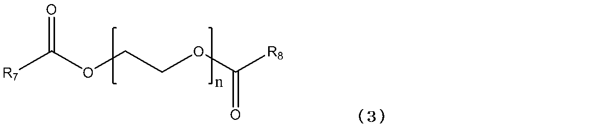
(式(3)中、R7、R8は、各々独立にメチル基又はエチル基である。また、nは1~4の整数である。)
溶媒(A)のより好適な例としては、式(1)で表される化合物、式(2)で表される化合物、式(3)で表される化合物、N-メチル-2-ピロリドン、ジメチルスルホキシドなどが挙げられる。これらは、1種のみを用いてもよいし、2種以上を混合して用いてもよい。
本発明の分散体は、各種重合性化合物(α)で修飾されたセラミック粒子(B)が、エネルギー線又は熱刺激により反応して、ネットワーク構造を形成し、上記したような溶媒を内包したまま硬化すると考えられる。従って、架橋密度が高いほどセラミック体の強度は高くなる。
セラミック粒子(B)を修飾する重合性化合物(α)は、セラミックの表面に配位及び/又は結合可能であり、エネルギー線の照射又は熱により重合する官能基をもつ物質であれば特に限定されない。重合性化合物(α)は、エネルギー線の照射又は熱により重合可能な重合性化合物(α)を単一成分で、または、その2種類以上を混合して用いることができる。重合性化合物(α)としては、有機カルボン酸化合物、シラン系化合物、金属カップリング剤、エポキシ基含有化合物、水酸基含有化合物、アミノ基含有化合物、チオール含有化合物などが挙げられる。重合反応は、ラジカル重合性、アニオン重合性、カチオン重合性、熱重合性など任意のものであってよい。
重合性化合物(α)のうち、エネルギー線の照射により重合する官能基をもつ重合性化合物としては、例えばビニル基を含有する重合性化合物が用いられるが、なかでも、エネルギー線の照射による重合速度が速い(メタ)アクリル系化合物及びスチレン系化合物が好ましい。
エネルギー線の照射により重合する官能基をもつ重合性化合物の例としては、アクリル酸、メタクリル酸、マレイン酸、フマル酸、2-(メタ)アクリロイロキシエチルコハク酸、2-(メタ)アクリロイロキシエチルヘキサヒドロフタル酸、2-(メタ)アクリロイロキシエチルフタル酸、ビニルトリメトキシシラン、ビニルトリエトキシシラン、3-(メタ)アクリロキシプロピルメチルジメトキシシラン、3-(メタ)アククリロキシプロピルトリメトキシシラン、3-(メタ)アクリロキシプロピルトリエトキシシラン、N-(2-アミノメチル)-3-アミノプロピルトリメトキシシラン、p-スチリルトリメトキシシラン、フェニルトリメトキシシラン、2-ヒドロキシエチル(メタ)アクリレート、2-ヒドロキシプロピル(メタ)アクリレート、3-ヒドロキシプロピル(メタ)アクリレート、2-ヒドロキシブチル(メタ)アクリレート、4-ヒドロキシブチル(メタ)アクリレートなどが挙げられる。
重合性化合物(α)のうち、熱により重合する官能基をもつ重合性化合物としては、上記ビニル基を含有する重合性化合物の他にエポキシ基を含有する重合性化合物などが挙げられる。
エポキシ基を含有する重合性化合物の例としては、エピクロロヒドリン、2-(3,4-エポキシシクロヘキシル)エチルトリメトキシシラン、3-グリシドキシプロピルメチルジメトキシシラン、3-グリシドキシプロピルトリメトキシシラン、3-グリシドキシプロピルメチルジエトキシシラン、3-グリシドキシプロピルトリエトキシシランなどが挙げられる。
また、上記セラミック粒子(B)は、上記重合性化合物(α)以外にも、セラミックの表面に配位及び/又は結合可能であれば重合性官能基を持たない化合物(β)(以下、化合物(β)と表記する場合がある)で、さらに修飾されていてもよい。化合物(β)は、セラミック粒子の溶媒中での分散性を向上させるために有効である。化合物(β)の例としては、酢酸、吉草酸、ヘキサン酸、へプタン酸、2-エチルヘキサン酸、オクタン酸、2-メチルへプタン酸、4-メチルオクタン酸、ノナン酸、デカン酸、ネオデカン酸、ドデカン酸、テトラデカン酸、ヘキサデカン酸、オクタデカン酸、オレイン酸、12-ヒドロキシステアリン酸、シクロヘキサノール、1-ブタノール、2-ブタノール、オレインアルコール、メチルシクロヘキサノール、エチレングリコールモノエチルエーテルなどが挙げられる。これらは、1種のみを用いても良いし、2種以上を組み合わせて用いてもよい。
本発明においてセラミック粒子(B)の表面修飾方法は、通常、セラミック粒子を修飾するために採用される方法を用いればよく、その方法は特に限定されるものではない。例えば、金属酸化物等のセラミックナノ粒子を窒素雰囲気下、反応槽に入れ攪拌しながら、重合性化合物(α)や化合物(β)を噴霧した後に100~150℃で1時間以上加熱攪拌し修飾する乾式法や、セラミック粒子(B)をスラリー化し、重合性化合物(α)及び化合物(β)を加え、熱を加えながら攪拌して修飾する湿式法どちらを用いても良い。また、ゾルゲル法や超臨界水熱合成法でセラミックナノ粒子を合成する時に表面修飾を行なっても良い。
好ましい実施形態において、前記分散体は、硬化後、硬化物中に残存する溶媒(A)が、硬化前の該溶媒の重量の80重量%以上残存し、より好ましくは90重量%以上残存するものを選択して使用することができる。このような溶媒(A)を用いることにより三次元形状のセラミック体を好適に作製することができる。
前記分散体中の粒子の平均分散粒子径は、5nm以上200nm以下であり、好ましくは5nm以上100nm以下である。この範囲であれば、分散安定性をより高めることができるので好ましい。また、より透明性の高い分散体を作製できるため、エネルギー線で硬化させる時に、エネルギー線をより内部まで透過させることができ、三次元形状の硬化物をより好適に作製することができるため好ましい。
前記分散体中のセラミック粒子(B)の含有量は、5vol%以上70vol%以下であり、好ましくは5vol%以上60vol%以下である。前記濃度範囲であれば、粒子間の距離が近く、ネットワーク構造が十分に形成されるたるため、溶媒を内包した硬化物を安定的に作成できる。
本発明の付加造形用分散体はセラミック粒子を含む。このセラミック粒子は単一であっても良いし、2種以上のセラミックの混合物、固溶体もしくは複合酸化物であっても良い。単一のセラミックの例としては、SiO2、Al2O3、TiO2、ZrO2、In2O3、ZnO、SnO2、La2O3、Y2O3、CeO2、MgO、Si3N4などが挙げられ、固溶体または複合酸化物の例としては、ITO、ATO、BaTiO3、CaTiO3、MgAl2O4、Al2O3-ZrO2、Y2O3-ZrO2、ベーマイト及び/またはMgO及び/またはCaO等で安定化したZrO2、Al2O3、Y2O3、HfO2、CeO2、Al2O3-ZrO2、Al2O3、Y2O3、Fe2O3、他の希土類酸化物で安定化したSi3N4などが挙げられる。
本発明の三次元形状セラミック体の製造においては、重合性官能基との反応性を有さず、且つ、分散体の硬化後、硬化物中に残存する溶媒(A)と、エネルギー線重合性官能基又は熱重合性官能基で修飾されたセラミック粒子(B)を必須成分として含有する分散体を、支持体上に層毎に供給してエネルギー線又は熱により硬化し、積層することによりセラミック体を製造する。
本発明における支持体とは、硬化前の分散液を保持できるものであればどのような形状、材質でもよく、例えば黒鉛板、プラチナ板、金属板、セラミック板、ガラス板等の平面支持体や、これらの材質でできた容器等の立体的な支持体などが挙げられる。
また、本発明における供給とは、分散体を支持体に接液させることであり、また、硬化した分散体の上にさらに、新しい分散体を接液させることである。供給の方法に制限はないが、塗布、滴下、印刷、ディッピングなどが挙げられる。
本発明における支持体とは、硬化前の分散液を保持できるものであればどのような形状、材質でもよく、例えば黒鉛板、プラチナ板、金属板、セラミック板、ガラス板等の平面支持体や、これらの材質でできた容器等の立体的な支持体などが挙げられる。
また、本発明における供給とは、分散体を支持体に接液させることであり、また、硬化した分散体の上にさらに、新しい分散体を接液させることである。供給の方法に制限はないが、塗布、滴下、印刷、ディッピングなどが挙げられる。
以下、本発明における実施態様の一例を下記するが、これらに限定されるわけではない。
具体的な製造法の例としては、分散体を少量ずつ支持体上に供給しエネルギー線又は熱により硬化させて積層する3D-インクジェット法や、容器に満たした分散体の中に支持体を設置し、外部から光または熱を加えて支持体に接液した分散体を硬化させ、支持体を上または下に移動させることにより、支持体及び硬化物に段階的に分散体を供給して硬化させ、三次元形状を作製する光造形法等が挙げられる。
本発明における別の製造法の例としては、規定された寸法を有する型の中に一度に分散体を供給し、エネルギー線または熱により硬化させる方法も可能である。規定された寸法を有する型とは、例えば、シャーレなどの容器、寒天などで作製した型やプリンターで印刷した型等が挙げられる。
具体的な製造法の例としては、分散体を少量ずつ支持体上に供給しエネルギー線又は熱により硬化させて積層する3D-インクジェット法や、容器に満たした分散体の中に支持体を設置し、外部から光または熱を加えて支持体に接液した分散体を硬化させ、支持体を上または下に移動させることにより、支持体及び硬化物に段階的に分散体を供給して硬化させ、三次元形状を作製する光造形法等が挙げられる。
本発明における別の製造法の例としては、規定された寸法を有する型の中に一度に分散体を供給し、エネルギー線または熱により硬化させる方法も可能である。規定された寸法を有する型とは、例えば、シャーレなどの容器、寒天などで作製した型やプリンターで印刷した型等が挙げられる。
本発明の三次元形状セラミック体の製造において、付加造形時の1層の厚さは、エネルギー線が透過するまたは熱が伝わる厚さで規定される。本発明の分散体は、セラミック粒子の分散粒径が小さく、分散体の透明性が非常に高いため、例えば光重合反応により、1mm<厚の層を一回で造形可能である。さらにこれを積層することにより、任意の厚さのセラミック体を造形できる。
本発明の三次元形状セラミック体の製造においては、セラミック粒子の表面修飾基を利用して硬化させるため、所望の表面修飾基を付与することができる粒子であれば、セラミックの種類は限定されない。さらに、有機部分を焼結等により除去することで、理論上目的とする無機成分の純度が100%のセラミックの造形物(セラミック焼結体)を作製できる。また、本発明により製造可能な造形物の種類は特に制限がなく、教育、玩具の分野における人物、動植物等を模した模型、工業分野における各種製品、動作確認や嵌合せ、質感、サイズ感の確認のための試作段階の模型等、躯体の構造確認、見本の作製等のような建築分野におけるミニチュア、医療用分野における臓器、骨等のモデル、義手、歯冠、人工骨等の製造などさまざまな造形物作製に適用可能である。
本発明の三次元形状セラミック体の製造においては、セラミック粒子の表面修飾基を利用して硬化させるため、所望の表面修飾基を付与することができる粒子であれば、セラミックの種類は限定されない。さらに、有機部分を焼結等により除去することで、理論上目的とする無機成分の純度が100%のセラミックの造形物(セラミック焼結体)を作製できる。また、本発明により製造可能な造形物の種類は特に制限がなく、教育、玩具の分野における人物、動植物等を模した模型、工業分野における各種製品、動作確認や嵌合せ、質感、サイズ感の確認のための試作段階の模型等、躯体の構造確認、見本の作製等のような建築分野におけるミニチュア、医療用分野における臓器、骨等のモデル、義手、歯冠、人工骨等の製造などさまざまな造形物作製に適用可能である。
以下、実施例を用いて本発明を更に詳しく説明するが、本発明は以下の実施例の範囲に限定されるものではない。
(実施例1)
メタクリル基修飾シリカ(株式会社アドマテックス製 アドマナノ YA010C-SM1 粒径10nm)10gをスクリュー管に秤量し、ジエチレングリコールエチルメチルエーテル(蒸気圧 91Pa/20℃、分子量:148) 10gと、光重合開始剤(BASFジャパン株式会社製 IRGACURE 184) 0.3gを加えて攪拌し、半透明のシリカ50重量%(30vol%)分散体を調製した。得られた分散体中のシリカ粒子の平均分散粒子径は15nmであった。得られたシリカ分散体1gをシャーレ(φ4cm)に量りとり、大気下で1000mJ/cm2の紫外線を照射した。その結果、溶媒を内包した透明な厚さ1~2mmの板状のセラミック体が作製できた。紫外線硬化前後の重量変化は、0.95%(溶媒残存量99%以上)であった。
メタクリル基修飾シリカ(株式会社アドマテックス製 アドマナノ YA010C-SM1 粒径10nm)10gをスクリュー管に秤量し、ジエチレングリコールエチルメチルエーテル(蒸気圧 91Pa/20℃、分子量:148) 10gと、光重合開始剤(BASFジャパン株式会社製 IRGACURE 184) 0.3gを加えて攪拌し、半透明のシリカ50重量%(30vol%)分散体を調製した。得られた分散体中のシリカ粒子の平均分散粒子径は15nmであった。得られたシリカ分散体1gをシャーレ(φ4cm)に量りとり、大気下で1000mJ/cm2の紫外線を照射した。その結果、溶媒を内包した透明な厚さ1~2mmの板状のセラミック体が作製できた。紫外線硬化前後の重量変化は、0.95%(溶媒残存量99%以上)であった。
本発明で用いた測定方法及び用いた測定装置は以下の通りである。
<平均分散粒子径の分析>
測定装置:大塚電子株式会社製 ゼータ電位・粒径測定システムELS-Z
<平均分散粒子径の分析>
測定装置:大塚電子株式会社製 ゼータ電位・粒径測定システムELS-Z
<紫外線照射装置>
ヘレウス株式会社製 無電極UVランプシステム F600V-10
ヘレウス株式会社製 無電極UVランプシステム F600V-10
(実施例2)
シャーレ(φ4cm)にあらかじめ、外径1cm(内径0.5cm)、高さ1.5cmの寒天で作製した筒状の型を置いた。この中に実施例1と同様にして調製したシリカ分散体 0.1gを注入し、大気下で300mJ/cm2の紫外線を照射して硬化させた。更にその上に、シリカ分散体 0.1gを注入して硬化させることを2回繰返し、合計で0.3gのシリカ分散体を円柱の中で積層し硬化させた。その結果、溶媒を内包した高さ1.2cmの透明なセラミック体が作製できた。紫外線硬化前後の重量変化は、1.0%(溶媒残存量99%)であった。
シャーレ(φ4cm)にあらかじめ、外径1cm(内径0.5cm)、高さ1.5cmの寒天で作製した筒状の型を置いた。この中に実施例1と同様にして調製したシリカ分散体 0.1gを注入し、大気下で300mJ/cm2の紫外線を照射して硬化させた。更にその上に、シリカ分散体 0.1gを注入して硬化させることを2回繰返し、合計で0.3gのシリカ分散体を円柱の中で積層し硬化させた。その結果、溶媒を内包した高さ1.2cmの透明なセラミック体が作製できた。紫外線硬化前後の重量変化は、1.0%(溶媒残存量99%)であった。
(実施例3)
シャーレ(φ4cm)にあらかじめ、外径1cm(内径0.5cm)、高さ1.5cmの寒天で作製した筒状の型を置いた。この中に実施例1と同様にして調製したシリカ分散体0.3gを注入し、大気下で1000mJ/cm2の紫外線を照射して硬化させた。その結果、溶媒を内包した高さ1.2cmの透明なセラミック体が作製できた。紫外線硬化前後の重量変化は、0.7%(溶媒残存量99%以上)であった。
シャーレ(φ4cm)にあらかじめ、外径1cm(内径0.5cm)、高さ1.5cmの寒天で作製した筒状の型を置いた。この中に実施例1と同様にして調製したシリカ分散体0.3gを注入し、大気下で1000mJ/cm2の紫外線を照射して硬化させた。その結果、溶媒を内包した高さ1.2cmの透明なセラミック体が作製できた。紫外線硬化前後の重量変化は、0.7%(溶媒残存量99%以上)であった。
(実施例4)
メタクリル基修飾シリカ(株式会社アドマテックス製 アドマナノ YA010C-SM1 粒径10nm) 4gをスクリュー管に秤量し、ジエチレングリコールエチルメチルエーテル(蒸気圧 91Pa/20℃、分子量:148) 16gと、光重合開始剤(BASFジャパン株式会社製 IRGACURE 184) 0.3gを加えて攪拌し、半透明のシリカ20重量%(10vol%)分散体を調製した。得られた分散体中のシリカ粒子の平均分散粒子径は15nmであった。得られたシリカ分散体を用いて、実施例1と同様の操作を行った結果、溶媒を内包した透明な厚さ1~2mmの板状のセラミック体が作製できた。紫外線硬化前後の重量変化は、0.8%(溶媒残存量99%以上)であった。
メタクリル基修飾シリカ(株式会社アドマテックス製 アドマナノ YA010C-SM1 粒径10nm) 4gをスクリュー管に秤量し、ジエチレングリコールエチルメチルエーテル(蒸気圧 91Pa/20℃、分子量:148) 16gと、光重合開始剤(BASFジャパン株式会社製 IRGACURE 184) 0.3gを加えて攪拌し、半透明のシリカ20重量%(10vol%)分散体を調製した。得られた分散体中のシリカ粒子の平均分散粒子径は15nmであった。得られたシリカ分散体を用いて、実施例1と同様の操作を行った結果、溶媒を内包した透明な厚さ1~2mmの板状のセラミック体が作製できた。紫外線硬化前後の重量変化は、0.8%(溶媒残存量99%以上)であった。
(実施例5)
メタクリル基修飾シリカ(株式会社アドマテックス製 アドマナノ YA010C-SM1 粒径10nm)12gをスクリュー管に秤量し、3-メトキシブチルアセテート(蒸気圧 400Pa/20℃、分子量:146.2)8gと、光重合開始剤(BASFジャパン株式会社製 IRGACURE 184) 0.3gを加えて攪拌し、半透明のシリカ60重量%(39vol%)の分散体を調製した。得られた分散体中のシリカ粒子の平均分散粒子径は16nmであった。得られたシリカ分散体を用いて、実施例1と同様の操作を行った結果、溶媒を内包した透明な厚さ1~2mmの板状のセラミック体が作製できた。紫外線硬化前後の重量変化は、1.9%(溶媒残存量98%以上)であった。
メタクリル基修飾シリカ(株式会社アドマテックス製 アドマナノ YA010C-SM1 粒径10nm)12gをスクリュー管に秤量し、3-メトキシブチルアセテート(蒸気圧 400Pa/20℃、分子量:146.2)8gと、光重合開始剤(BASFジャパン株式会社製 IRGACURE 184) 0.3gを加えて攪拌し、半透明のシリカ60重量%(39vol%)の分散体を調製した。得られた分散体中のシリカ粒子の平均分散粒子径は16nmであった。得られたシリカ分散体を用いて、実施例1と同様の操作を行った結果、溶媒を内包した透明な厚さ1~2mmの板状のセラミック体が作製できた。紫外線硬化前後の重量変化は、1.9%(溶媒残存量98%以上)であった。
(実施例6)
メタクリル基修飾シリカ(株式会社アドマテックス製 アドマナノ YA010C-SM1 粒径10nm)4gをスクリュー管に秤量し、3-メトキシブチルアセテート(蒸気圧 400Pa/20℃、分子量146.2) 16gと、光重合開始剤(BASFジャパン株式会社製 IRGACURE 184) 0.3gを加えて攪拌し、半透明のシリカ20重量%(10vol%)の分散体を調製した。得られた分散体中のシリカ粒子の平均分散粒子径は15nmであった。得られたシリカ分散体を用いて、実施例1と同様の操作を行った結果、溶媒を内包した透明な厚さ1~2mmの板状のセラミック体が作製できた。紫外線硬化前後の重量変化は、1.8%(溶媒残存量98%以上)であった。
メタクリル基修飾シリカ(株式会社アドマテックス製 アドマナノ YA010C-SM1 粒径10nm)4gをスクリュー管に秤量し、3-メトキシブチルアセテート(蒸気圧 400Pa/20℃、分子量146.2) 16gと、光重合開始剤(BASFジャパン株式会社製 IRGACURE 184) 0.3gを加えて攪拌し、半透明のシリカ20重量%(10vol%)の分散体を調製した。得られた分散体中のシリカ粒子の平均分散粒子径は15nmであった。得られたシリカ分散体を用いて、実施例1と同様の操作を行った結果、溶媒を内包した透明な厚さ1~2mmの板状のセラミック体が作製できた。紫外線硬化前後の重量変化は、1.8%(溶媒残存量98%以上)であった。
(実施例7)
メタクリル基修飾シリカ(株式会社アドマテックス製 アドマナノ YA010C-SM1 粒径10nm)12.8gをスクリュー管に秤量し、プロピレングリコールモノエチルエーテル(蒸気圧 533Pa/20℃、分子量:140.2) 7.2gと、光重合開始剤(BASFジャパン株式会社製 IRGACURE 184) 0.3gを加えて攪拌し、半透明のシリカ64重量%(約42vol%)の分散体を調製した。得られた分散体中のシリカ粒子の平均分散粒子径は18nmであった。得られたシリカ分散体1gをシャーレ(φ4cm)に量りとり、これに、大気下で660mJ/cm2の紫外線を照射した。その結果、溶媒を内包した透明な厚さ1~2mmの板状のセラミック体が作製できた。紫外線硬化前後の重量変化は、2.6%(溶媒残存量97%以上)であった。
メタクリル基修飾シリカ(株式会社アドマテックス製 アドマナノ YA010C-SM1 粒径10nm)12.8gをスクリュー管に秤量し、プロピレングリコールモノエチルエーテル(蒸気圧 533Pa/20℃、分子量:140.2) 7.2gと、光重合開始剤(BASFジャパン株式会社製 IRGACURE 184) 0.3gを加えて攪拌し、半透明のシリカ64重量%(約42vol%)の分散体を調製した。得られた分散体中のシリカ粒子の平均分散粒子径は18nmであった。得られたシリカ分散体1gをシャーレ(φ4cm)に量りとり、これに、大気下で660mJ/cm2の紫外線を照射した。その結果、溶媒を内包した透明な厚さ1~2mmの板状のセラミック体が作製できた。紫外線硬化前後の重量変化は、2.6%(溶媒残存量97%以上)であった。
(実施例8)
メタクリル基修飾シリカ(株式会社アドマテックス製 アドマナノ YA010C-SM1 粒径10nm)4gをスクリュー管に秤量し、プロピレングリコールモノエチルエーテル(蒸気圧 533Pa/20℃、分子量:140.2) 16gと、光重合開始剤(BASFジャパン株式会社製 IRGACURE 184) 0.3gを加えて攪拌し、半透明のシリカ20重量%(約9vol%)の分散体を調製した。得られた分散体中のシリカ粒子の平均分散粒子径は17nmであった。得られたシリカ分散体を用いて、実施例1と同様の操作を行った結果、溶媒を内包した透明な厚さ1~2mmの板状のセラミック体が作製できた。紫外線硬化前後の重量変化は、5.4%(溶媒残存量94%以上)であった。
メタクリル基修飾シリカ(株式会社アドマテックス製 アドマナノ YA010C-SM1 粒径10nm)4gをスクリュー管に秤量し、プロピレングリコールモノエチルエーテル(蒸気圧 533Pa/20℃、分子量:140.2) 16gと、光重合開始剤(BASFジャパン株式会社製 IRGACURE 184) 0.3gを加えて攪拌し、半透明のシリカ20重量%(約9vol%)の分散体を調製した。得られた分散体中のシリカ粒子の平均分散粒子径は17nmであった。得られたシリカ分散体を用いて、実施例1と同様の操作を行った結果、溶媒を内包した透明な厚さ1~2mmの板状のセラミック体が作製できた。紫外線硬化前後の重量変化は、5.4%(溶媒残存量94%以上)であった。
(実施例9)
メタクリル基修飾シリカ(株式会社アドマテックス製 アドマナノ YA010C-SM1 粒径10nm)8.4gをスクリュー管に秤量し、エチレングリコールモノメチルエーテル(蒸気圧 840Pa/20℃、分子量:76.1) 11.6gと、光重合開始剤(BASFジャパン株式会社製 IRGACURE 184) 0.3gを加えて攪拌し、半透明のシリカ42重量%(約24vol%)の分散体を調製した。得られた分散体中のシリカ粒子の平均分散粒子径は17nmであった。得られたシリカ分散体1gをシャーレ(φ4cm)に量りとり、これに、大気下で660mJ/cm2の紫外線を照射した。その結果、溶媒を内包した透明な厚さ1~2mmの板状のセラミック体が作製できた。紫外線硬化前後の重量変化は、5.4%(溶媒残存量94%以上)であった。
メタクリル基修飾シリカ(株式会社アドマテックス製 アドマナノ YA010C-SM1 粒径10nm)8.4gをスクリュー管に秤量し、エチレングリコールモノメチルエーテル(蒸気圧 840Pa/20℃、分子量:76.1) 11.6gと、光重合開始剤(BASFジャパン株式会社製 IRGACURE 184) 0.3gを加えて攪拌し、半透明のシリカ42重量%(約24vol%)の分散体を調製した。得られた分散体中のシリカ粒子の平均分散粒子径は17nmであった。得られたシリカ分散体1gをシャーレ(φ4cm)に量りとり、これに、大気下で660mJ/cm2の紫外線を照射した。その結果、溶媒を内包した透明な厚さ1~2mmの板状のセラミック体が作製できた。紫外線硬化前後の重量変化は、5.4%(溶媒残存量94%以上)であった。
(実施例10)
メタクリル基修飾シリカ(株式会社アドマテックス製 アドマナノ YA010C-SM1 粒径10nm)4gをスクリュー管に秤量し、エチレングリコールモノメチルエーテル(蒸気圧 840Pa/20℃、分子量:76.1) 16gと、光重合開始剤(BASFジャパン株式会社製 IRGACURE 184) 0.3gを加えて攪拌し、半透明のシリカ20重量%(10vol%)の分散体を調製した。得られた分散体中のシリカ粒子の平均分散粒子径は16nmであった。得られたシリカ分散体を用いて、実施例1と同様の操作を行った結果、溶媒を内包した透明な厚さ1~2mmの板状のセラミック体が作製できた。紫外線硬化前後の重量変化は、6.7%(溶媒残存量93%以上)であった。
メタクリル基修飾シリカ(株式会社アドマテックス製 アドマナノ YA010C-SM1 粒径10nm)4gをスクリュー管に秤量し、エチレングリコールモノメチルエーテル(蒸気圧 840Pa/20℃、分子量:76.1) 16gと、光重合開始剤(BASFジャパン株式会社製 IRGACURE 184) 0.3gを加えて攪拌し、半透明のシリカ20重量%(10vol%)の分散体を調製した。得られた分散体中のシリカ粒子の平均分散粒子径は16nmであった。得られたシリカ分散体を用いて、実施例1と同様の操作を行った結果、溶媒を内包した透明な厚さ1~2mmの板状のセラミック体が作製できた。紫外線硬化前後の重量変化は、6.7%(溶媒残存量93%以上)であった。
(実施例11)
メタクリル基修飾シリカ(株式会社アドマテックス製 アドマナノ YA010C-SM1 粒径10nm)4gをスクリュー管に秤量し、N-メチル-2-ピロリドン(蒸気圧 39Pa/20℃、分子量:99.1) 16gと、光重合開始剤(BASFジャパン株式会社製 IRGACURE 184) 0.3gを加えて攪拌し、半透明のシリカ20重量%(11vol%)の分散体を調製した。得られた分散体中のシリカ粒子の平均分散粒子径は16nmであった。得られたシリカ分散体を用いて、実施例1と同様の操作を行った結果、溶媒を内包した透明な厚さ1~2mmの板状のセラミック体が作製できた。紫外線硬化前後の重量変化は、0.7%(溶媒残存量99%以上)であった。
メタクリル基修飾シリカ(株式会社アドマテックス製 アドマナノ YA010C-SM1 粒径10nm)4gをスクリュー管に秤量し、N-メチル-2-ピロリドン(蒸気圧 39Pa/20℃、分子量:99.1) 16gと、光重合開始剤(BASFジャパン株式会社製 IRGACURE 184) 0.3gを加えて攪拌し、半透明のシリカ20重量%(11vol%)の分散体を調製した。得られた分散体中のシリカ粒子の平均分散粒子径は16nmであった。得られたシリカ分散体を用いて、実施例1と同様の操作を行った結果、溶媒を内包した透明な厚さ1~2mmの板状のセラミック体が作製できた。紫外線硬化前後の重量変化は、0.7%(溶媒残存量99%以上)であった。
(実施例12)
メタクリル基修飾シリカ(株式会社アドマテックス製 アドマナノ YA010C-SM1 粒径10nm)4gをスクリュー管に秤量し、ジメチルスルホキシド(蒸気圧 84Pa/20℃、分子量:78.1) 16gと、光重合開始剤(BASFジャパン株式会社製 IRGACURE 184) 0.3gを加えて攪拌し、半透明のシリカ20重量%(約11vol%)の分散体を調製した。得られた分散体中のシリカ粒子の平均分散粒子径は21nmであった。得られたシリカ分散体を用いて、実施例1と同様の操作を行った結果、溶媒を内包した透明な厚さ1~2mmの板状のセラミック体が作製できた。紫外線硬化前後の重量変化は、0.8%(溶媒残存量99%以上)であった。
メタクリル基修飾シリカ(株式会社アドマテックス製 アドマナノ YA010C-SM1 粒径10nm)4gをスクリュー管に秤量し、ジメチルスルホキシド(蒸気圧 84Pa/20℃、分子量:78.1) 16gと、光重合開始剤(BASFジャパン株式会社製 IRGACURE 184) 0.3gを加えて攪拌し、半透明のシリカ20重量%(約11vol%)の分散体を調製した。得られた分散体中のシリカ粒子の平均分散粒子径は21nmであった。得られたシリカ分散体を用いて、実施例1と同様の操作を行った結果、溶媒を内包した透明な厚さ1~2mmの板状のセラミック体が作製できた。紫外線硬化前後の重量変化は、0.8%(溶媒残存量99%以上)であった。
(合成例1)
フラスコに、シリカ100g(日本アエロジル株式会社製 AEROSIL200 粒径12nm)を量りとり、メチルエチルケトン60g、3-グリシドキシプロピルトリメトキシシラン20g、水1gを加え、窒素雰囲気下、攪拌しながら80℃で2時間加熱還流した。この液を遠心分離し、上清を捨て、メチルエチルケトンで3回洗浄した後、乾燥してエポキシ基修飾シリカを調製した。
フラスコに、シリカ100g(日本アエロジル株式会社製 AEROSIL200 粒径12nm)を量りとり、メチルエチルケトン60g、3-グリシドキシプロピルトリメトキシシラン20g、水1gを加え、窒素雰囲気下、攪拌しながら80℃で2時間加熱還流した。この液を遠心分離し、上清を捨て、メチルエチルケトンで3回洗浄した後、乾燥してエポキシ基修飾シリカを調製した。
(実施例13)
上記合成例1で合成したエポキシ基修飾シリカ 4gをスクリュー管に秤量し、N-メチル-2-ピロリドン(蒸気圧 39Pa/20℃、分子量:99.1) 16gと、硬化触媒2-エチル-4-メチルイミダゾール 1gを加えて攪拌し、半透明のシリカ20重量%(10vol%)の分散体を調製した。得られた分散体中のシリカ粒子の平均分散粒子径は35nmであった。得られたシリカ分散体 1gをシャーレ(φ4cm)に量りとり、120℃で3分間加熱し硬化させた。その結果、溶媒を内包した透明な厚さ1~2mmの板状のセラミック体が作製できた。熱硬化前後の重量変化は、0.7%(溶媒残存量99%以上)であった。
上記合成例1で合成したエポキシ基修飾シリカ 4gをスクリュー管に秤量し、N-メチル-2-ピロリドン(蒸気圧 39Pa/20℃、分子量:99.1) 16gと、硬化触媒2-エチル-4-メチルイミダゾール 1gを加えて攪拌し、半透明のシリカ20重量%(10vol%)の分散体を調製した。得られた分散体中のシリカ粒子の平均分散粒子径は35nmであった。得られたシリカ分散体 1gをシャーレ(φ4cm)に量りとり、120℃で3分間加熱し硬化させた。その結果、溶媒を内包した透明な厚さ1~2mmの板状のセラミック体が作製できた。熱硬化前後の重量変化は、0.7%(溶媒残存量99%以上)であった。
(実施例14)
上記合成例1で合成したエポキシ基修飾シリカ 6gをスクリュー管に秤量し、N-メチル-2-ピロリドン(蒸気圧 39Pa/20℃、分子量:99.1) 14gと、硬化触媒2-エチル-4-メチルイミダゾール 1.5gを加えて攪拌し、半透明のシリカ30重量%(17vol%)の分散体を調製した。得られた分散体中のシリカ粒子の平均分散粒子径は40nmであった。得られたシリカ分散体 1gをシャーレ(φ4cm)に量りとり、120℃で3分間加熱し硬化させた。その結果、溶媒を内包した透明な厚さ1~2mmの板状のセラミック体が作製できた。熱硬化前後の重量変化は、0.7%(溶媒残存量99%以上)であった。
上記合成例1で合成したエポキシ基修飾シリカ 6gをスクリュー管に秤量し、N-メチル-2-ピロリドン(蒸気圧 39Pa/20℃、分子量:99.1) 14gと、硬化触媒2-エチル-4-メチルイミダゾール 1.5gを加えて攪拌し、半透明のシリカ30重量%(17vol%)の分散体を調製した。得られた分散体中のシリカ粒子の平均分散粒子径は40nmであった。得られたシリカ分散体 1gをシャーレ(φ4cm)に量りとり、120℃で3分間加熱し硬化させた。その結果、溶媒を内包した透明な厚さ1~2mmの板状のセラミック体が作製できた。熱硬化前後の重量変化は、0.7%(溶媒残存量99%以上)であった。
(実施例15)
上記合成例1で合成したエポキシ基修飾シリカ 4gをスクリュー管に秤量し、ジエチレングリコールモノエチルエーテルアセテート(蒸気圧 13Pa/20℃、分子量:176.2) 16gと、硬化触媒2-エチル-4-メチルイミダゾール 1gを加えて攪拌し、半透明のシリカ20重量%(10vol%)の分散体を調製した。得られた分散体中のシリカ粒子の平均分散粒子径は30nmであった。得られたシリカ分散体1gをシャーレ(φ4cm)に量りとり、120℃で3分間硬化させた。その結果、溶媒を内包した透明な厚さ1~2mmの板状のセラミック体が作製できた。熱硬化前後の重量変化は、7.8%(溶媒残存量92%以上)であった。
上記合成例1で合成したエポキシ基修飾シリカ 4gをスクリュー管に秤量し、ジエチレングリコールモノエチルエーテルアセテート(蒸気圧 13Pa/20℃、分子量:176.2) 16gと、硬化触媒2-エチル-4-メチルイミダゾール 1gを加えて攪拌し、半透明のシリカ20重量%(10vol%)の分散体を調製した。得られた分散体中のシリカ粒子の平均分散粒子径は30nmであった。得られたシリカ分散体1gをシャーレ(φ4cm)に量りとり、120℃で3分間硬化させた。その結果、溶媒を内包した透明な厚さ1~2mmの板状のセラミック体が作製できた。熱硬化前後の重量変化は、7.8%(溶媒残存量92%以上)であった。
(比較例1)
メタクリル基修飾シリカ(アドマナノシリカ 粒径 10nm) 11gをスクリュー管に秤量し、メチルエチルケトン(蒸気圧 10500Pa/20℃) 9gと、光重合開始剤イルガキュア184 0.3gを加えて攪拌し、半透明のシリカ55重量%(33vol%)の分散体を調製した。得られた分散体中のシリカ粒子の平均分散粒子径は15nmであった。得られたシリカ分散体を用いて、実施例1と同様の操作を行った結果、小さな白い塊が多数生成し、板状のセラミック体は作製できなかった。紫外線照射前後の重量変化は25.4%減量(溶媒残存量80%以下)であった。
(比較例2)
合成例1で合成したエポキシ基修飾シリカ 11gをスクリュー管に秤量し、メチルエチルケトン(蒸気圧 10500Pa/20℃) 9gと、硬化触媒2-エチル-4-メチルイミダゾール2.8gを加えて攪拌し、半透明のシリカ55重量%(約33vol%)の分散体を調製した。得られた分散体中のシリカ粒子の平均分散粒子径は25nmであった。調製したシリカ分散体1gをシャーレ(φ4cm)に量りとり、120℃で3分間硬化させた結果、溶媒がほぼ全量減量(溶媒残存量10%以下)し、多数の小さな白い塊が生成、板状のセラミック体は作製できなかった。
メタクリル基修飾シリカ(アドマナノシリカ 粒径 10nm) 11gをスクリュー管に秤量し、メチルエチルケトン(蒸気圧 10500Pa/20℃) 9gと、光重合開始剤イルガキュア184 0.3gを加えて攪拌し、半透明のシリカ55重量%(33vol%)の分散体を調製した。得られた分散体中のシリカ粒子の平均分散粒子径は15nmであった。得られたシリカ分散体を用いて、実施例1と同様の操作を行った結果、小さな白い塊が多数生成し、板状のセラミック体は作製できなかった。紫外線照射前後の重量変化は25.4%減量(溶媒残存量80%以下)であった。
(比較例2)
合成例1で合成したエポキシ基修飾シリカ 11gをスクリュー管に秤量し、メチルエチルケトン(蒸気圧 10500Pa/20℃) 9gと、硬化触媒2-エチル-4-メチルイミダゾール2.8gを加えて攪拌し、半透明のシリカ55重量%(約33vol%)の分散体を調製した。得られた分散体中のシリカ粒子の平均分散粒子径は25nmであった。調製したシリカ分散体1gをシャーレ(φ4cm)に量りとり、120℃で3分間硬化させた結果、溶媒がほぼ全量減量(溶媒残存量10%以下)し、多数の小さな白い塊が生成、板状のセラミック体は作製できなかった。


表中の丸印は、セラミック体が作製でき、かつ硬化後の溶媒残存量が80重量%以上のものを示す。
Claims (15)
- 20℃における蒸気圧が1500Pa以下であり、かつ、重合性官能基との反応性を有さない溶媒(A)と、エネルギー線重合性官能基又は熱重合性官能基で修飾されたセラミック粒子(B)と、を含有する分散体が、支持体に層毎又は一度に供給される工程(I)と、支持体に供給された分散体をエネルギー線又は熱により硬化させる工程(II)と、を含むことを特徴とするセラミック体の製造方法。
- 前記工程(I)が、前記分散体が支持体に層毎に供給される工程である、請求項1に記載のセラミック体の製造方法。
- 前記工程(I)中、供給される方法が塗布である請求項1に記載のセラミック体の製造方法。
- 前記工程(I)中、供給される方法が印刷である請求項1に記載のセラミック体の製造方法。
- 前記溶媒(A)の20℃における蒸気圧が1000Pa以下であることを特徴とする請求項1に記載のセラミック体の製造方法。
- 前記溶媒(A)が、下記式(1)で表される化合物、下記式(2)で表される化合物、下記式(3)で表される化合物、N-メチル-2-ピロリドン及びジメチルスルホキシドからなる群より選ばれる1種又は2種以上の化合物である請求項1に記載のセラミック体の製造方法。

- セラミック体の各々の層が、硬化前、硬化後ともに、0.05μm~50000μmの厚さを有することを特徴とする請求項1に記載のセラミック体の製造方法。
- セラミック体の各々の層が、溶媒を乾燥する工程を経ることなく、セラミックの表面修飾基がエネルギー線又は熱により分散媒である溶媒を内包して硬化することを特徴とする請求項1に記載のセラミック体の製造方法。
- 請求項1~8で得られたセラミック体を乾燥又は焼結する工程を有する、セラミック焼結体の製造方法。
- 20℃における蒸気圧が1500Pa以下であり、かつ、重合性官能基との反応性を有さない溶媒(A)と、エネルギー線重合性官能基又は熱重合性官能基で修飾されたセラミック粒子(B)と、を含有することを特徴とする造形用分散体。
- 前記溶媒(A)の20℃における蒸気圧が1000Pa以下であることを特徴とする請求項10に記載の造形用分散体。
- 前記溶媒(A)が、下記式(1)で表される化合物、下記式(2)で表される化合物、下記式(3)で表される化合物、N-メチル-2-ピロリドン及びジメチルスルホキシドからなる群より選ばれる1種又は2種以上の化合物であることを特徴とする請求項10に記載の造形用分散体。


- 前記セラミック粒子(B)を修飾しているエネルギー線重合性官能基又は熱重合性官能基が、アクリル系重合基又はスチレン系重合基又はエポキシ系重合基であることを特徴とする請求項10に記載の造形用分散体。
- 前記分散体中の粒子の平均分散粒子径が、5nm以上200nm以下である請求項10に記載の造形用分散体。
- 前記分散体中のセラミック粒子(B)の含有量が、5vol%以上90vol%以下である請求項10に記載の造形用分散体。
Applications Claiming Priority (2)
| Application Number | Priority Date | Filing Date | Title |
|---|---|---|---|
| JP2015247329 | 2015-12-18 | ||
| JP2015-247329 | 2015-12-18 |
Publications (1)
| Publication Number | Publication Date |
|---|---|
| WO2017104528A1 true WO2017104528A1 (ja) | 2017-06-22 |
Family
ID=59056473
Family Applications (1)
| Application Number | Title | Priority Date | Filing Date |
|---|---|---|---|
| PCT/JP2016/086521 Ceased WO2017104528A1 (ja) | 2015-12-18 | 2016-12-08 | セラミック体の製造方法及びそれに用いる分散体 |
Country Status (2)
| Country | Link |
|---|---|
| JP (1) | JP6942960B2 (ja) |
| WO (1) | WO2017104528A1 (ja) |
Cited By (1)
| Publication number | Priority date | Publication date | Assignee | Title |
|---|---|---|---|---|
| CN117486597A (zh) * | 2023-10-27 | 2024-02-02 | 苏州璋驰光电科技有限公司 | 一种基于激光烧结3D打印MgAl2O4粉体的透明陶瓷的制备方法 |
Families Citing this family (2)
| Publication number | Priority date | Publication date | Assignee | Title |
|---|---|---|---|---|
| JP6922423B2 (ja) * | 2017-05-29 | 2021-08-18 | Dic株式会社 | セラミック体の製造方法 |
| WO2019178599A1 (en) * | 2018-03-16 | 2019-09-19 | Nano-Dimension Technologies, Ltd. | Inkjet printing of three-dimensional ceramic pattern |
Citations (5)
| Publication number | Priority date | Publication date | Assignee | Title |
|---|---|---|---|---|
| JPH06329460A (ja) * | 1993-05-24 | 1994-11-29 | Toshiba Ceramics Co Ltd | セラミックスの光学的成形方法 |
| JP2006076822A (ja) * | 2004-09-09 | 2006-03-23 | Jsr Corp | セラミックス造形用紫外線硬化性樹脂組成物、セラミックス成型体の製造方法及びセラミックス前駆体 |
| JP2006151709A (ja) * | 2004-11-25 | 2006-06-15 | National Institute Of Advanced Industrial & Technology | セラミックス成形体及びその製造方法 |
| JP2010031279A (ja) * | 2008-07-30 | 2010-02-12 | Ivoclar Vivadent Ag | 歯科用セラミックの立体リトグラフによる調製のための光硬化性スリップ |
| JP2012017327A (ja) * | 2010-07-08 | 2012-01-26 | Ivoclar Vivadent Ag | 高強度セラミックの立体リソグラフィ調製のための光硬化性セラミックスリップ |
Family Cites Families (7)
| Publication number | Priority date | Publication date | Assignee | Title |
|---|---|---|---|---|
| JPH0672756A (ja) * | 1992-08-25 | 1994-03-15 | Sumitomo Metal Ind Ltd | グリーンシートの製造方法 |
| JPH0891940A (ja) * | 1994-09-21 | 1996-04-09 | Toshiba Ceramics Co Ltd | セラミックスの光学的成形法 |
| JP2000281863A (ja) * | 1999-03-30 | 2000-10-10 | Jsr Corp | 樹脂組成物及びその硬化物 |
| JP4029242B2 (ja) * | 1999-03-25 | 2008-01-09 | 株式会社村田製作所 | セラミックグリーンシート、セラミック基板及びセラミック多層基板の製造方法 |
| JP2001302943A (ja) * | 2000-04-20 | 2001-10-31 | Jsr Corp | 反応性粒子、それを含む硬化性組成物及びその硬化物 |
| KR100533627B1 (ko) * | 2003-06-19 | 2005-12-06 | 삼성전기주식회사 | 세라믹 슬러리 조성물 |
| JP4620705B2 (ja) * | 2007-04-24 | 2011-01-26 | Jsr株式会社 | 光硬化性液状組成物、立体形状物及びこれらの製造方法 |
-
2016
- 2016-12-07 JP JP2016237536A patent/JP6942960B2/ja active Active
- 2016-12-08 WO PCT/JP2016/086521 patent/WO2017104528A1/ja not_active Ceased
Patent Citations (5)
| Publication number | Priority date | Publication date | Assignee | Title |
|---|---|---|---|---|
| JPH06329460A (ja) * | 1993-05-24 | 1994-11-29 | Toshiba Ceramics Co Ltd | セラミックスの光学的成形方法 |
| JP2006076822A (ja) * | 2004-09-09 | 2006-03-23 | Jsr Corp | セラミックス造形用紫外線硬化性樹脂組成物、セラミックス成型体の製造方法及びセラミックス前駆体 |
| JP2006151709A (ja) * | 2004-11-25 | 2006-06-15 | National Institute Of Advanced Industrial & Technology | セラミックス成形体及びその製造方法 |
| JP2010031279A (ja) * | 2008-07-30 | 2010-02-12 | Ivoclar Vivadent Ag | 歯科用セラミックの立体リトグラフによる調製のための光硬化性スリップ |
| JP2012017327A (ja) * | 2010-07-08 | 2012-01-26 | Ivoclar Vivadent Ag | 高強度セラミックの立体リソグラフィ調製のための光硬化性セラミックスリップ |
Cited By (1)
| Publication number | Priority date | Publication date | Assignee | Title |
|---|---|---|---|---|
| CN117486597A (zh) * | 2023-10-27 | 2024-02-02 | 苏州璋驰光电科技有限公司 | 一种基于激光烧结3D打印MgAl2O4粉体的透明陶瓷的制备方法 |
Also Published As
| Publication number | Publication date |
|---|---|
| JP2017114117A (ja) | 2017-06-29 |
| JP6942960B2 (ja) | 2021-09-29 |
Similar Documents
| Publication | Publication Date | Title |
|---|---|---|
| US20210139720A1 (en) | 3d polymerizable ceramic inks | |
| JP7255915B2 (ja) | 光硬化3dプリントアイテムの製造方法およびその使用法 | |
| JP5841753B2 (ja) | 高強度セラミックの立体リソグラフィ調製のための光硬化性セラミックスリップ | |
| JP6412926B2 (ja) | 熱硬化性コーティングシステム | |
| CN112707734B (zh) | 一种基于3d打印的石墨烯/陶瓷有序复合材料制备方法 | |
| US11975996B2 (en) | Composition for inorganic molded article production use, and method for producing inorganic molded article | |
| KR101025003B1 (ko) | 무기물나노졸의 표면제어를 통한 기능성 무기물후막의제조방법과 이에 의해 제조된 무기물후막 | |
| CN104149337A (zh) | 一种用于三维打印的光固化材料及其应用方法 | |
| CN105531237A (zh) | 用于隔热玻璃单元的真空窗用玻璃支柱 | |
| JP6942960B2 (ja) | セラミック体の製造方法及びそれに用いる分散体 | |
| Sarraf et al. | Preceramic polymers for additive manufacturing of silicate ceramics | |
| JP2005067998A (ja) | 光学的立体造形用スラリー、光学的立体造形物の製造方法及び光学的立体造形物 | |
| KR20230162652A (ko) | 투명 다성분 용융 실리카 유리의 제조 및 성형을 위한 재료 및 공정 | |
| CN107735372A (zh) | 烧结成形体及其制造方法、具备烧结成形体的物品、烧结成形体用材料以及烧结前成形体及其制造方法 | |
| CN112795044A (zh) | 一种复合透明膜,其制备方法及基于其的连续光固化3d打印陶瓷方法 | |
| KR20230160886A (ko) | 투명 세라믹의 제조 및 성형을 위한 재료 및 공정 | |
| JP2007123261A (ja) | ステレオリソグラフィーを用いたセラミック製放電容器の製造方法 | |
| CN116063064A (zh) | 一种陶瓷的光固化增材制造方法 | |
| Zhao et al. | Additive manufacturing of alumina-based ceramic structures by vat photopolymerization: A review of strategies for improving shaping accuracy and properties | |
| CN112848304B (zh) | 一种电场辅助连续面曝光3d打印有序复合材料的制备方法 | |
| CN111825333A (zh) | 一种玻璃浆料及其制备方法和3d打印玻璃器件的方法 | |
| JP2021535010A (ja) | ガラス及びセラミックを製造するための相分離性の付加製造用組成物 | |
| JP6922423B2 (ja) | セラミック体の製造方法 | |
| KR20200075939A (ko) | 광경화 3d 프린팅용 무기산화물-모노머 복합 조성물 및 그 제조방법 | |
| JP2007261822A (ja) | 独立ガラスフィルムの製造方法 |
Legal Events
| Date | Code | Title | Description |
|---|---|---|---|
| 121 | Ep: the epo has been informed by wipo that ep was designated in this application |
Ref document number: 16875508 Country of ref document: EP Kind code of ref document: A1 |
|
| NENP | Non-entry into the national phase |
Ref country code: DE |
|
| 122 | Ep: pct application non-entry in european phase |
Ref document number: 16875508 Country of ref document: EP Kind code of ref document: A1 |