WO2017104386A1 - ガラス板の製造方法及び製造装置 - Google Patents
ガラス板の製造方法及び製造装置 Download PDFInfo
- Publication number
- WO2017104386A1 WO2017104386A1 PCT/JP2016/085076 JP2016085076W WO2017104386A1 WO 2017104386 A1 WO2017104386 A1 WO 2017104386A1 JP 2016085076 W JP2016085076 W JP 2016085076W WO 2017104386 A1 WO2017104386 A1 WO 2017104386A1
- Authority
- WO
- WIPO (PCT)
- Prior art keywords
- glass plate
- support
- support member
- main surface
- scribe line
- Prior art date
- Legal status (The legal status is an assumption and is not a legal conclusion. Google has not performed a legal analysis and makes no representation as to the accuracy of the status listed.)
- Ceased
Links
Images



Classifications
-
- B—PERFORMING OPERATIONS; TRANSPORTING
- B28—WORKING CEMENT, CLAY, OR STONE
- B28D—WORKING STONE OR STONE-LIKE MATERIALS
- B28D5/00—Fine working of gems, jewels, crystals, e.g. of semiconductor material; apparatus or devices therefor
-
- C—CHEMISTRY; METALLURGY
- C03—GLASS; MINERAL OR SLAG WOOL
- C03B—MANUFACTURE, SHAPING, OR SUPPLEMENTARY PROCESSES
- C03B33/00—Severing cooled glass
- C03B33/02—Cutting or splitting sheet glass or ribbons; Apparatus or machines therefor
- C03B33/023—Cutting or splitting sheet glass or ribbons; Apparatus or machines therefor the sheet or ribbon being in a horizontal position
- C03B33/033—Apparatus for opening score lines in glass sheets
-
- C—CHEMISTRY; METALLURGY
- C03—GLASS; MINERAL OR SLAG WOOL
- C03B—MANUFACTURE, SHAPING, OR SUPPLEMENTARY PROCESSES
- C03B33/00—Severing cooled glass
- C03B33/02—Cutting or splitting sheet glass or ribbons; Apparatus or machines therefor
-
- C—CHEMISTRY; METALLURGY
- C03—GLASS; MINERAL OR SLAG WOOL
- C03B—MANUFACTURE, SHAPING, OR SUPPLEMENTARY PROCESSES
- C03B33/00—Severing cooled glass
- C03B33/02—Cutting or splitting sheet glass or ribbons; Apparatus or machines therefor
- C03B33/023—Cutting or splitting sheet glass or ribbons; Apparatus or machines therefor the sheet or ribbon being in a horizontal position
- C03B33/03—Glass cutting tables; Apparatus for transporting or handling sheet glass during the cutting or breaking operations
-
- Y—GENERAL TAGGING OF NEW TECHNOLOGICAL DEVELOPMENTS; GENERAL TAGGING OF CROSS-SECTIONAL TECHNOLOGIES SPANNING OVER SEVERAL SECTIONS OF THE IPC; TECHNICAL SUBJECTS COVERED BY FORMER USPC CROSS-REFERENCE ART COLLECTIONS [XRACs] AND DIGESTS
- Y02—TECHNOLOGIES OR APPLICATIONS FOR MITIGATION OR ADAPTATION AGAINST CLIMATE CHANGE
- Y02P—CLIMATE CHANGE MITIGATION TECHNOLOGIES IN THE PRODUCTION OR PROCESSING OF GOODS
- Y02P40/00—Technologies relating to the processing of minerals
- Y02P40/50—Glass production, e.g. reusing waste heat during processing or shaping
- Y02P40/57—Improving the yield, e-g- reduction of reject rates
Definitions
- the present invention relates to a glass plate manufacturing method and a manufacturing apparatus for forming a scribe line on a glass plate.
- FPD flat panel displays
- liquid crystal displays plasma displays
- field emission displays including surface emission displays
- electroluminescence displays and sensor substrates
- glass plates such as a cover for a semiconductor package such as a solid-state imaging device or a laser diode, and a substrate for a thin film compound solar cell are used.
- the glass plate to be produced has a strip shape.
- This strip-shaped glass plate has ears thicker than the center in the width direction at both ends in the width direction (see, for example, Patent Document 1).
- the center part in the width direction which is thinner than the ear part is the product, and the ear part is an unnecessary part. Therefore, the ear is usually removed before the glass plate is shipped as a product.
- the cutting for removing the ear portion for example, a method of forming a scribe line with a cutter on a glass plate in a vertical posture, and then performing folding along the scribe line is employed.
- a scribe line is formed on a glass plate with a cutter
- the glass plate is supported by a support surface arranged to face the cutter via the glass plate.
- the glass plate has such a warp (hereinafter referred to as vertical warpage), when a scribe line is formed on the glass plate, a gap is generated between the glass plate and the support surface, and the scribe line may not enter well. There was sex. Alternatively, if the glass plate is pressed against the support surface in order to successfully form the scribe line, unnecessary stress may be generated on the glass and the glass plate may be broken.
- an object of the present invention is to provide a glass plate manufacturing method and a manufacturing apparatus capable of forming a good scribe line even if the glass plate has a vertical warp.
- the glass plate manufacturing method of the present invention which was created to solve the above problems, includes a first support member that supports a glass plate having a first main surface and a second main surface in a vertical position, and the glass plate.
- the glass plate since the support surface is inclined with respect to the vertical direction when the scribe line is formed, the glass plate fits into the support surface by its own weight (extends on the support surface), and the support surface and the glass plate There is no gap between them. For this reason, it becomes possible to form a favorable scribe line on the glass plate. That is, according to the manufacturing method of the glass plate of this invention, it is possible to provide the manufacturing method of the glass plate which can form a favorable scribe line even if it is a glass plate which has a vertical curvature.
- an inclination angle of the support surface in the inclined posture with respect to a vertical direction is not less than 0.5 ° and not more than 20 °.
- a drive unit that movably supports the second support member is used, and the drive unit supports the second support member on the second main surface of the glass plate; It is preferable that the support position is supported so as to be able to advance and retreat between a standby position retracted from the support position to the side opposite to the glass plate.
- the drive unit is configured so that an inclination angle with respect to a vertical direction of the support surface at the standby position is smaller than an inclination angle with respect to the vertical direction of the support surface at the support position in the inclined posture. It is preferable to support the second support member.
- the inclination angle with respect to the vertical direction of the support surface at the standby position includes 0 °.
- the support surface is in a posture along the vertical direction (vertical posture).
- the driving unit includes an upper moving mechanism connected to an upper portion of the second support member and a lower moving mechanism connected to a lower portion of the second support member, and the second support member is It is preferable that the amount of advancement of the second support member by the lower moving mechanism is larger than the amount of advancement of the second support member by the upper moving mechanism during advancement from the standby position toward the support position.
- the second support member can be tilted while the second support member is advanced from the standby position toward the support position.
- the first support member is swingable in the thickness direction of the glass plate in the vertical posture.
- a pressing member having a pressing surface that presses the first main surface of the glass plate supported by the support surface in the inclined posture.
- the pressing surface further allows the glass plate to become familiar with the supporting surface (extends on the supporting surface), and eliminates a gap between the supporting surface and the glass plate.
- the pressing surface presses the first main surface of the glass plate supported by the support surface in the inclined posture at least in the initial stage when the scribe line is formed.
- the pressing surface is separated from the first main surface during the formation of the scribe line.
- the scribe line can be more favorably formed on the first main surface of the glass plate.
- the glass plate manufacturing apparatus of the present invention which was created to solve the above-mentioned problems, includes a first support member for supporting a glass plate having a first main surface and a second main surface in a vertical position, and the glass.
- An apparatus for producing a glass plate comprising: a second support member having a support surface for supporting a surface, wherein the support surface is inclined with respect to a vertical direction when the scribe line is formed, and the glass is The second main surface of the plate is supported.
- the glass plate manufacturing apparatus of the present invention it is possible to provide a glass plate manufacturing apparatus capable of forming a good scribe line even with a glass plate having a vertical warp.
- the present invention it is possible to provide a glass plate manufacturing method and a manufacturing apparatus capable of forming a good scribe line even with a glass plate having a vertical warp.
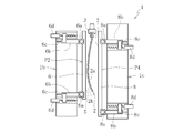
- FIG. 4 is a schematic side view similar to FIG. 3, showing a state in which a glass plate is supported on an inclined support surface.
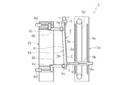
- FIG. 3 is a schematic side view similar to FIG. 2, showing a state in which a glass plate is supported by an inclined support surface. It is the figure which looked at a mode that a scribe line is formed in the state supported by the support surface which inclined the glass plate from the bottom.
- FIG. 5 is a schematic side view similar to FIG. 4, showing a case where the gripping member can swing.
- the manufacturing apparatus 1 to 3 show a glass plate manufacturing apparatus (hereinafter referred to as manufacturing apparatus 1) according to an embodiment of the present invention.
- the manufacturing apparatus 1 is for forming a scribe line on the glass plate 2, but these drawings show a stage before the scribe line is formed on the glass plate 2.
- the manufacturing apparatus 1 includes a glass chuck 3 as a first support member that supports a glass plate 2 having a first main surface 2 a and a second main surface 2 b in a vertical posture, and a first main surface of the glass plate 2.
- the wheel cutter 4 for forming a scribe line in the vertical direction on 2a, the second support member 6 having the support surface 5 for supporting the second main surface 2b of the glass plate 2, and the first main surface 2a of the glass plate 2 are pressed.
- a presser member 8 having a presser surface 7.
- the support surface 5 is in a state of being arranged to face the wheel cutter 4 through the glass plate 2 when forming a scribe line.
- the manufacturing apparatus 1 is disposed on the first main surface 2a side of the glass plate 2, and includes a wheel cutter driving portion 1a that supports the wheel cutter 4 so as to be movable, and a second main surface 2b of the glass plate 2.
- 2nd support member drive part 1b which is arranged in the side and supports the 2nd support member 6 so that movement is possible, and it is arranged in the 1st principal surface 2a side of glass plate 2, and can move presser member 8 And a pressing member driving portion 1c to be supported.
- the glass plate 2 has a rectangular shape, and is obtained by cutting a strip-shaped glass manufactured by the overflow downdraw method in the width direction.
- the strip-shaped glass plate used as the base material of the glass plate 2 is manufactured by the overflow down draw method as follows. That is, a glass raw material is melted in a melting furnace to form molten glass, this molten glass is supplied to the upper part of the molded body arranged inside the molding furnace, and the belt-shaped molten glass flowing down from this molded body is conveyed by a roller.
- the belt-shaped glass plate is produced by gradually cooling while cooling.
- the glass plate 2 has thick ear portions 2c at both ends in the horizontal direction (left and right direction in FIG. 1) of the glass plate 2 from the center in the horizontal direction of the glass plate 2. As shown in FIGS. 2 and 3, the glass plate 2 has a vertical warp that is curved so that the second main surface 2 b is convex. Such vertical warpage is eliminated by cutting and removing the ear portion 2c, and a flat glass plate 2 is obtained.
- the manufacturing apparatus 1 forms a scribe line on the glass plate 2 in order to perform cutting for removing the ear portion 2c.
- the planned scribe line L is a boundary between a region to be a product and a region to be cut out together with the ear portion 2c.
- the size of the product region of the glass plate 2 is, for example, 250 mm ⁇ 340 mm to 2830 mm ⁇ 3030 mm.
- region used as the product of the glass plate 2 can be 500 micrometers or less, 300 micrometers or less, 200 micrometers or less, 100 micrometers or less, 50 micrometers or less, for example.
- a plurality of glass chucks 3 are arranged at intervals in the horizontal direction of the glass plate 2.
- the glass chuck 3 holds the upper end of the glass plate 2.
- the glass plate 2 is not supported by anything except the glass chuck 3, and the glass plate 2 is suspended by the glass chuck 3.
- the wheel cutter 4 can be displaced in each of the thickness direction and the vertical direction of the glass plate 2 in a vertical posture.
- the wheel cutter 4 is provided on the cutter head 9.
- a cylinder for pressing the wheel cutter 4 against the glass plate 2 with a predetermined pressure is built in the cutter head 9.
- the cutter head 9 is driven by a cutter servomotor 9a via a ball screw and moves in the lateral direction of FIG. As the cutter head 9 moves, the wheel cutter 4 moves along the lateral direction of FIG.
- the cutter head 9 and the cutter servo motor 9a are attached to a cutter slide member 9b.
- the cutter slide member 9b is slidably attached to the cutter rail 9c.
- the cutter slide member 9b is driven by the timing belt 9d, is guided by the cutter rail 9c, and moves along the vertical direction of FIG.
- the wheel cutter 4 moves along the vertical direction of FIG. 3 by the movement of the cutter slide member 9b.
- the cutter rail 9c and the timing belt 9d drive section are fixed to the housing of the wheel cutter drive section 1a.
- the support surface 5 is a flat surface, and supports the second main surface 2b of the glass plate 2 when a scribe line is formed by the wheel cutter 4.
- the support surface 5 has an inclined posture inclined toward the second main surface 2b in the thickness direction of the glass plate 2 in the vertical posture with respect to the vertical direction when the scribe line is formed.
- the support surface 5 is not inclined in the state of FIGS. 2 and 3, and has a vertical posture along the vertical direction.
- the second support member 6 having the support surface 5 is made of, for example, a metal such as iron, stainless steel, or aluminum, or a material obtained by bonding rubber or resin to a metal material.
- the inclination angle with respect to the vertical direction of the support surface 5 in the inclined posture at the time of forming the scribe line is preferably 0.5 ° or more and 20 ° or less, more preferably 1 ° or more and 18 ° or less, Most preferably, it is 2 ° or more and 15 ° or less.
- the inclination angle is less than 0.5 °, the effect due to the inclination may not be sufficiently obtained.
- the inclination angle exceeds 20 °, the vicinity of the center in the horizontal direction of the glass plate 2 hangs down by its own weight, and there is a concern about an adverse effect caused by this.
- the second support member drive unit 1 b includes a second support member 6, a support position P ⁇ b> 1 that supports the second main surface 2 b of the glass plate 2, and a glass plate from the support position P ⁇ b> 1. 2 is supported so as to be able to move forward and backward with respect to the support standby position P2 retracted to the opposite side.
- the support surface 5 of the second support member 6 at the support position P1 is in an inclined posture when the scribe line is formed.
- the inclination angle (in the present embodiment, 0 °) with respect to the vertical direction of the support surface 5 at the support standby position P2 (in the thickness direction of the vertical glass plate 2) is the inclination posture of the support surface 5 at the support position P1. It is smaller than the inclination angle (in the thickness direction of the glass plate 2 in the vertical position) with respect to the vertical direction.
- the second support member drive unit 1 b includes a second support member upper moving mechanism connected to the upper portion of the second support member 6 and a second support member lower moving mechanism connected to the lower portion of the second support member 6.
- the advance amount d1 of the second support member 6 by the second support member lower moving mechanism is the upper movement for the second support member.
- the advance amount d2 of the second support member 6 by the mechanism is larger. Thereby, the support surface 5 of the 2nd support member 6 becomes an inclination posture at the time of formation of a scribe line.
- the second support member slide member 6b is attached to the upper end and the lower end of the second support member 6 on which the support surface 5 is formed via the second support member bearing case 6a.
- the second support member slide member 6b is slidably attached to the second support member rail 6c.
- the second support member slide member 6b is driven by a second support member servomotor 6d via a ball screw, and is guided by the second support member rail 6c to move along the lateral direction of FIGS. .
- the upper end and the lower end of the support surface 5 move along the lateral direction of FIGS.
- the second support member bearing case 6a the second support member slide member 6b, the second support member rail 6c, the ball screw, and the second support member servomotor 6d that are installed in a pair on the upper side and the lower side.
- the upper moving mechanism for the second supporting member is configured on the upper side
- the lower moving mechanism for the second supporting member is configured on the lower side.
- the second support member rail 6c and the second support member servomotor 6d are fixed to the housing of the second support member drive portion 1b. Further, when the support surface 5 is inclined, the lower end of the second support member 6 moves not only in the lateral direction of FIGS. 3 and 4 but also to the upper side. It is configured to be allowed between the support member bearing case 6 a and the second support member 6.
- the pressing surface 7 is for pressing the first main surface 2a against the glass plate 2 supported by the supporting surface 5 in the inclined posture at the time of forming the scribe line.
- the pressing surface 7 is a flat surface and presses the first main surface 2 a on the outer side in the lateral direction of the glass plate 2 than the support surface 5.
- the pressing surface 7 is positioned between the second support member 6 and the ear portion 2 c in the lateral direction of the glass plate 2.
- the pressing surface 7 has an inclined posture inclined toward the second main surface 2b in the thickness direction of the glass plate 2 in the vertical posture with respect to the vertical direction when the scribe line is formed. In the state of FIG. 2, the pressing surface 7 is not inclined but has a vertical posture along the vertical direction.
- the pressing surface 7 is made of a material having cushioning properties such as a resin material such as rubber.
- the inclination angle with respect to the vertical direction of the pressing surface 7 in the inclined posture when the scribe line is formed is the same as the inclination angle with respect to the vertical direction of the support surface 5 in the inclined posture when the scribe line is formed.
- the pressing member drive unit 1 c is configured so that the pressing member 8 is opposite to the pressing position P3 that supports the second main surface 2 b of the glass plate 2 and from the pressing position P3 to the glass plate 2. It is supported so as to be able to advance and retreat between the presser standby position P4 retracted to the side.
- the presser surface 7 of the presser member 8 at the presser position P3 is in an inclined posture when the scribe line is formed.
- the inclination angle (0 ° in the present embodiment) with respect to the vertical direction of the presser surface 7 at the presser standby position P4 is the tilted posture of the presser surface 7 at the presser position P3. It is smaller than the inclination angle (in the thickness direction of the glass plate 2 in the vertical position) with respect to the vertical direction.
- the pressing member drive unit 1 c includes a pressing member upper moving mechanism connected to the upper portion of the pressing member 8 and a pressing member lower moving mechanism connected to the lower portion of the pressing member 8.
- the advance amount of the presser member 8 by the presser member lower moving mechanism is larger than the advance amount of the presser member 8 by the presser member upper moving mechanism. Is also small. As a result, the presser surface 7 of the presser member 8 assumes an inclined posture when the scribe line is formed.
- the presser member upper moving mechanism and the presser member lower moving mechanism are the same as those of the support surface 5.
- the pressing member slide member 8b is attached to the upper end and the lower end of the pressing member 8 on which the pressing surface 7 is formed via the pressing member bearing case 8a.
- the pressing member slide member 8b is slidably attached to the pressing member rail 8c.
- the pressing member slide member 8b is driven by a pressing member servo motor 8d via a ball screw, guided by the pressing member rail 8c, and moved along the lateral direction of FIGS.
- the pressing member slide member 8b By the movement of the pressing member slide member 8b, the upper end and the lower end of the pressing surface 7 are moved along the lateral direction of FIGS.
- the presser member bearing case 8a the presser member slide member 8b, the presser member rail 8c, the ball screw, and the presser member servomotor 8d that are installed on the upper side and the lower side
- the upper side of The upper moving mechanism is configured
- the lower moving mechanism for the pressing member is configured on the lower side.
- the presser member rail 8c and the presser member servo motor 8d are fixed to the housing of the presser member driving portion 1c. Further, when the presser surface 7 is inclined, the lower end of the presser member 8 moves not only in the lateral direction of FIGS. 2 and 5 but also to the upper side. It is configured to be allowed between the lower end and the pressing member bearing case 8a.
- the glass plate 2 that is suspended and supported on the glass chuck 3 in a vertical posture is supplied to the manufacturing apparatus 1 from the depth direction in FIG. 3 (lateral direction in FIG. 1).
- the second support member slide member 6b is driven by the second support member servomotor 6d and moves from the support standby position P2 to the support position P1.
- the support surface 5 of the second support member 6 supports the second main surface 2 b of the glass plate 2 in an inclined posture.
- the pressing member slide member 8b is driven by the pressing member servo motor 8d and moves from the pressing standby position P4 to the pressing position P3.
- the pressing surface 7 of the pressing member 8 presses the first main surface 2a of the glass plate 2 in an inclined posture.
- the wheel cutter 4 applies the first main surface 2a to the first main surface 2a.
- a scribe line is formed toward the upper side.
- the wheel cutter 4 moves from the initial position (position in FIG. 3) and comes into contact with the lower end of the first main surface 2 a of the glass plate 2. From this state, as shown in FIG. 6, the wheel cutter 4 forms a scribe line on the first main surface 2 a of the glass plate 2 upward. When the wheel cutter 4 reaches the upper end of the first main surface 2a of the glass plate 2 and the formation of the scribe line is completed, the wheel cutter 4 returns to the initial position.
- the presser member slide member 8b is driven by the presser member servomotor 8d from the state shown in FIG. 5, and moves from the presser position P3 to the presser standby position P4. It becomes the state of 4. Accordingly, the restraint of the glass plate 2 on the second support member 6 by the press surface 7 of the press member 8 is released.
- the second support member slide member 6b is driven by the second support member servomotor 6d to move from the support position P1 to the support standby position P2.
- the glass plate 2 is suspended and supported by the glass chuck 3 in a vertical posture.
- the glass plate 2 is discharged from the manufacturing apparatus 1 in the depth direction of FIG. 3 (lateral direction of FIG. 1) while being supported in a suspended state on the glass chuck 3.
- the manufacturing apparatus 1 of the present embodiment configured as described above, since the support surface 5 is inclined with respect to the vertical direction when the scribe line is formed, the glass plate 2 is applied to the support surface 5 by its own weight. Familiarity (extends on the support surface 5), there is no gap between the support surface 5 and the glass plate 2. For this reason, it becomes possible to form a favorable scribe line on the glass plate 2. That is, according to the manufacturing apparatus 1 of the present embodiment, it is possible to provide a glass plate manufacturing method and a manufacturing apparatus capable of forming a good scribe line even if the glass plate 2 has a vertical warp.
- the present invention is not limited to the above embodiment, and various modifications are possible within the scope of the technical idea.
- the glass chuck 3 does not swing.
- the glass chuck 3 is in the first principal surface 2a in the thickness direction of the glass plate 2 in the vertical posture. On the other side, it may be swingable.
- the glass plate 2 had the vertical curvature curved so that the 2nd main surface 2b side might become convex
- the vertical direction curved so that the 1st main surface 2a side might become convex. It may have a warp, or a part thereof may be curved so that the second main surface 2b side is convex, and another part may have a vertical warp that is curved so that the first main surface 2a side is convex. It may be.
- the 2nd support member 6 when forming a scribe line, advances to the support position P1, and when not forming a scribe line, the 2nd support member 6 is the standby position for support.
- the second support member 6 may not move, and the support surface 5 may always be inclined with respect to the vertical direction.
- the glass plate 2 held by the glass chuck 3 is placed on the side of the support surface 5 so that the second main surface 2b of the glass plate 2 is supported by the support surface 5 when the scribe line is formed. Configured to move to.
- the pressing surface 7 holds the first main surface 2a during the entire period when the scribe line is formed, but in some periods such as the initial period, the intermediate period, and the final period. There may be.
- the pressing member slide member 8b is driven by the pressing member servomotor 8d, It is preferable to move from the presser position P3 to the presser standby position P4 and release the restraint of the glass plate 2 on the second support member 6 by the presser surface 7 of the presser member 8.
- the scribe line can be favorably formed on the first main surface 2a. .
- the pressing surface 7 is separated from the first main surface 2a after the wheel cutter 4 forms a scribe line of 1 cm to 30 cm on the first main surface 2a.
- the manufacturing apparatus 1 may not include the pressing surface 7 for pressing the first main surface 2a of the glass plate 2.
- the formation of the scribe line with respect to the glass plate 2 by the wheel cutter 4 was performed toward the upper side, you may be performed toward the lower side.
- the scribe line formed by the wheel cutter 4 may not reach the upper end or the lower end of the first main surface 2a of the glass plate 2, and the formation of the scribe line is started from within the surface of the first main surface 2a.
- the formation of the scribe line may be finished in the plane of the first main surface 2a.
- the glass plate 2 was manufactured by the overflow downdraw method and had the ear
Landscapes
- Chemical & Material Sciences (AREA)
- Engineering & Computer Science (AREA)
- Materials Engineering (AREA)
- Organic Chemistry (AREA)
- Mechanical Engineering (AREA)
- Re-Forming, After-Treatment, Cutting And Transporting Of Glass Products (AREA)
- Processing Of Stones Or Stones Resemblance Materials (AREA)
Abstract
Description
1b 第2支持部材用駆動部
2 ガラス板
2a 第1主面
2b 第2主面
3 ガラスチャック(第1支持部材)
4 ホイールカッター
5 支持面
6 第2支持部材
6a 第2支持部材用ベアリングケース(上部及び下部移動機構)
6b 第2支持部材用スライド部材(上部及び下部移動機構)
6c 第2支持部材用レール(上部及び下部移動機構)
6d 第2支持部材用サーボモータ(上部及び下部移動機構)
7 押え面
8 押え部材
d1 前進量
d2 前進量
L スクライブ予定線
P1 支持位置
P2 支持用待機位置
Claims (10)
- 第1主面と第2主面を有するガラス板を、縦姿勢で吊り下げ支持する第1支持部材と、前記ガラス板の前記第1主面にスクライブ線を縦方向に形成するカッターと、前記スクライブ線の形成時に、前記ガラス板を介して前記カッターと対向配置された状態で、前記ガラス板の前記第2主面を支持する支持面を有する第2支持部材とを使用するガラス板の製造方法であって、
前記支持面が、前記スクライブ線の形成時に、鉛直方向に対して傾斜した傾斜姿勢で、前記ガラス板の前記第2主面を支持することを特徴とするガラス板の製造方法。 - 前記傾斜姿勢の前記支持面の鉛直方向に対する傾斜角度が、0.5°以上で20°以下であることを特徴とする請求項1に記載のガラス板の製造方法。
- 前記第2支持部材を移動可能に支持する駆動部を使用し、
前記駆動部は、前記第2支持部材を、前記ガラス板の前記第2主面を支持する支持位置と、前記支持位置から前記ガラス板とは反対側に後退した待機位置との間で進退移動可能に支持していることを特徴とする請求項1又は2に記載のガラス板の製造方法。 - 前記駆動部は、前記待機位置における前記支持面の鉛直方向に対する傾斜角度が、前記支持位置における前記支持面の前記傾斜姿勢での鉛直方向に対する傾斜角度よりも小さくなるように、前記第2支持部材を支持していることを特徴とする請求項3に記載のガラス板の製造方法。
- 前記駆動部は、前記第2支持部材の上部に接続された上部移動機構と、前記第2支持部材の下部に接続された下部移動機構とを備え、
前記第2支持部材を前記待機位置から前記支持位置へ向かって前進させる間に、前記下部移動機構による前記第2支持部材の前進量を、前記上部移動機構による前記第2支持部材の前進量よりも大きくしたことを特徴とする請求項4に記載のガラス板の製造方法。 - 前記第1支持部材が、前記縦姿勢にある前記ガラス板の厚さ方向に揺動可能であることを特徴とする請求項1~5の何れか1項に記載のガラス板の製造方法。
- 前記傾斜姿勢の前記支持面に支持された前記ガラス板の前記第1主面を押える押え面を有する押え部材を使用することを特徴とする請求項1~6の何れか1項に記載のガラス板の製造方法。
- 前記スクライブ線を形成する時の少なくとも初期に、前記押え面が、前記傾斜姿勢の前記支持面に支持された前記ガラス板の前記第1主面を押えていることを特徴とする請求項7に記載のガラス板の製造方法。
- 前記押え面は、前記スクライブ線の形成中に、前記第1主面から離反することを特徴とする請求項8に記載のガラス板の製造方法。
- 第1主面と第2主面を有するガラス板を、縦姿勢で吊り下げ支持する第1支持部材と、前記ガラス板の前記第1主面にスクライブ線を縦方向に形成するカッターと、前記スクライブ線の形成時に、前記ガラス板を介して前記カッターと対向配置された状態で、前記ガラス板の前記第2主面を支持する支持面を有する第2支持部材とを備えたガラス板の製造装置であって、
前記支持面が、前記スクライブ線の形成時に、鉛直方向に対して傾斜した傾斜姿勢で、前記ガラス板の前記第2主面を支持することを特徴とするガラス板の製造装置。
Priority Applications (3)
| Application Number | Priority Date | Filing Date | Title |
|---|---|---|---|
| JP2017555954A JP6681050B2 (ja) | 2015-12-15 | 2016-11-25 | ガラス板の製造方法及び製造装置 |
| CN201680057679.5A CN108137374B (zh) | 2015-12-15 | 2016-11-25 | 玻璃板的制造方法及制造装置 |
| KR1020187002367A KR102497949B1 (ko) | 2015-12-15 | 2016-11-25 | 유리판의 제조 방법 및 제조 장치 |
Applications Claiming Priority (2)
| Application Number | Priority Date | Filing Date | Title |
|---|---|---|---|
| JP2015-244032 | 2015-12-15 | ||
| JP2015244032 | 2015-12-15 |
Publications (1)
| Publication Number | Publication Date |
|---|---|
| WO2017104386A1 true WO2017104386A1 (ja) | 2017-06-22 |
Family
ID=59056249
Family Applications (1)
| Application Number | Title | Priority Date | Filing Date |
|---|---|---|---|
| PCT/JP2016/085076 Ceased WO2017104386A1 (ja) | 2015-12-15 | 2016-11-25 | ガラス板の製造方法及び製造装置 |
Country Status (4)
| Country | Link |
|---|---|
| JP (1) | JP6681050B2 (ja) |
| KR (1) | KR102497949B1 (ja) |
| CN (1) | CN108137374B (ja) |
| WO (1) | WO2017104386A1 (ja) |
Cited By (2)
| Publication number | Priority date | Publication date | Assignee | Title |
|---|---|---|---|---|
| JPWO2022097324A1 (ja) * | 2020-11-06 | 2022-05-12 | ||
| WO2022130750A1 (ja) * | 2020-12-18 | 2022-06-23 | 日本電気硝子株式会社 | 板ガラスの製造方法及び割断装置 |
Families Citing this family (1)
| Publication number | Priority date | Publication date | Assignee | Title |
|---|---|---|---|---|
| JP7216339B2 (ja) * | 2019-07-03 | 2023-02-01 | 日本電気硝子株式会社 | 割断装置及びガラス板の製造方法 |
Citations (3)
| Publication number | Priority date | Publication date | Assignee | Title |
|---|---|---|---|---|
| JP2006124194A (ja) * | 2004-10-26 | 2006-05-18 | Nippon Electric Glass Co Ltd | ガラス板の切断分離方法及びその装置 |
| JP2010507560A (ja) * | 2006-10-26 | 2010-03-11 | コーニング インコーポレイテッド | 衝撃で誘発される脆弱な材料内におけるクラックの伝播 |
| JP2015044713A (ja) * | 2013-08-28 | 2015-03-12 | 日本電気硝子株式会社 | 薄板ガラスの切断方法、およびガラス物品の製造方法 |
Family Cites Families (10)
| Publication number | Priority date | Publication date | Assignee | Title |
|---|---|---|---|---|
| EP1350769A1 (de) * | 2002-04-04 | 2003-10-08 | Bystronic Maschinen AG | Vorrichtung und Verfahren zum Teilen von vertikalen Glasplatten |
| AT412197B (de) * | 2002-11-22 | 2004-11-25 | Lisec Peter | Vorrichtung zum bearbeiten von werkstoffplatten |
| ITTV20030092A1 (it) * | 2003-06-24 | 2004-12-25 | For El Base Di Davanzo Nadia & C S Nc | Dispositivo per la correzione della geometria di taglio e per l'esecuzione del taglio obliquo o curvilineo delle lastre di vetro e procedimento per la correzione della geometria di taglio e per l'esecuzione del taglio obliquo o curvilineo delle lastr |
| US20060249553A1 (en) * | 2005-05-06 | 2006-11-09 | Ljerka Ukrainczyk | Ultrasonic induced crack propagation in a brittle material |
| JP2006321695A (ja) * | 2005-05-20 | 2006-11-30 | Central Glass Co Ltd | 板ガラスの折割装置 |
| US8146385B2 (en) * | 2010-04-29 | 2012-04-03 | Corning Incorporated | Methods for separating glass sheets from continuous glass ribbons |
| JP5589824B2 (ja) | 2010-12-21 | 2014-09-17 | 日本電気硝子株式会社 | ガラス板製造方法、ガラス板製造装置及びガラスロール |
| JP2014005170A (ja) | 2012-06-25 | 2014-01-16 | Nippon Electric Glass Co Ltd | ガラス板の製造方法 |
| JP6392238B2 (ja) * | 2012-12-07 | 2018-09-19 | コーニング インコーポレイテッド | ガラス板平坦化のための装置及びガラス板を平坦化する方法 |
| JP2014156360A (ja) * | 2013-02-14 | 2014-08-28 | Gy Systems Co Ltd | 折割装置 |
-
2016
- 2016-11-25 WO PCT/JP2016/085076 patent/WO2017104386A1/ja not_active Ceased
- 2016-11-25 JP JP2017555954A patent/JP6681050B2/ja active Active
- 2016-11-25 CN CN201680057679.5A patent/CN108137374B/zh active Active
- 2016-11-25 KR KR1020187002367A patent/KR102497949B1/ko active Active
Patent Citations (3)
| Publication number | Priority date | Publication date | Assignee | Title |
|---|---|---|---|---|
| JP2006124194A (ja) * | 2004-10-26 | 2006-05-18 | Nippon Electric Glass Co Ltd | ガラス板の切断分離方法及びその装置 |
| JP2010507560A (ja) * | 2006-10-26 | 2010-03-11 | コーニング インコーポレイテッド | 衝撃で誘発される脆弱な材料内におけるクラックの伝播 |
| JP2015044713A (ja) * | 2013-08-28 | 2015-03-12 | 日本電気硝子株式会社 | 薄板ガラスの切断方法、およびガラス物品の製造方法 |
Cited By (5)
| Publication number | Priority date | Publication date | Assignee | Title |
|---|---|---|---|---|
| JPWO2022097324A1 (ja) * | 2020-11-06 | 2022-05-12 | ||
| WO2022097324A1 (ja) * | 2020-11-06 | 2022-05-12 | 日本電気硝子株式会社 | 板ガラスの製造方法、その製造装置及び板ガラス |
| CN116261507A (zh) * | 2020-11-06 | 2023-06-13 | 日本电气硝子株式会社 | 板玻璃的制造方法、板玻璃的制造装置以及板玻璃 |
| JP7811341B2 (ja) | 2020-11-06 | 2026-02-05 | 日本電気硝子株式会社 | 板ガラスの製造方法、その製造装置及び板ガラス |
| WO2022130750A1 (ja) * | 2020-12-18 | 2022-06-23 | 日本電気硝子株式会社 | 板ガラスの製造方法及び割断装置 |
Also Published As
| Publication number | Publication date |
|---|---|
| CN108137374A (zh) | 2018-06-08 |
| CN108137374B (zh) | 2020-09-15 |
| KR20180092928A (ko) | 2018-08-20 |
| JPWO2017104386A1 (ja) | 2018-10-04 |
| KR102497949B1 (ko) | 2023-02-09 |
| JP6681050B2 (ja) | 2020-04-15 |
Similar Documents
| Publication | Publication Date | Title |
|---|---|---|
| US8029879B2 (en) | Display device having pair of glass substrates and method for cutting it | |
| US10766804B2 (en) | Glass film production method | |
| JP5129826B2 (ja) | 脆性材料基板のブレイク方法 | |
| JP5800646B2 (ja) | チップ間隔維持方法 | |
| JP4947488B2 (ja) | ガラス板の製造方法及びその装置 | |
| JP2011088382A (ja) | ブレイク装置およびブレイク方法 | |
| JP2014083821A (ja) | 脆性材料基板の分断方法並びに分断装置 | |
| KR101861755B1 (ko) | 유리판 분리 장치 | |
| US7789121B2 (en) | Sheet sticking apparatus and sticking method | |
| WO2017104386A1 (ja) | ガラス板の製造方法及び製造装置 | |
| US7814954B2 (en) | Sheet sticking apparatus and sticking method | |
| JP6364789B2 (ja) | スクライブ装置 | |
| US20190152826A1 (en) | Method for manufacturing glass roll | |
| JP2010023071A (ja) | 貼り合わせ基板の端子加工方法 | |
| JP2018062433A (ja) | ガラス物品の製造方法及びその製造設備 | |
| JP2018024057A (ja) | 樹脂シート切断機 | |
| US20090120587A1 (en) | Sheet sticking table | |
| JP6689023B2 (ja) | ブレーク装置 | |
| JP2015139966A (ja) | 脆性材料基板のスクライブ装置 | |
| KR20160029677A (ko) | 보호 테이프 박리 방법 및 보호 테이프 박리 장치 | |
| JP2008265003A (ja) | セラミックグリーンシート積層体の切断装置 | |
| TW202128543A (zh) | 玻璃膜的製造方法 | |
| JP5276736B2 (ja) | ブレイク方法 | |
| JP2009297938A (ja) | 超音波溶着機 | |
| TWI486315B (zh) | Sheet breaking device for sheet metal |
Legal Events
| Date | Code | Title | Description |
|---|---|---|---|
| 121 | Ep: the epo has been informed by wipo that ep was designated in this application |
Ref document number: 16875370 Country of ref document: EP Kind code of ref document: A1 |
|
| ENP | Entry into the national phase |
Ref document number: 2017555954 Country of ref document: JP Kind code of ref document: A |
|
| ENP | Entry into the national phase |
Ref document number: 20187002367 Country of ref document: KR Kind code of ref document: A |
|
| NENP | Non-entry into the national phase |
Ref country code: DE |
|
| 122 | Ep: pct application non-entry in european phase |
Ref document number: 16875370 Country of ref document: EP Kind code of ref document: A1 |