WO2017104155A1 - 接合方法 - Google Patents
接合方法 Download PDFInfo
- Publication number
- WO2017104155A1 WO2017104155A1 PCT/JP2016/071077 JP2016071077W WO2017104155A1 WO 2017104155 A1 WO2017104155 A1 WO 2017104155A1 JP 2016071077 W JP2016071077 W JP 2016071077W WO 2017104155 A1 WO2017104155 A1 WO 2017104155A1
- Authority
- WO
- WIPO (PCT)
- Prior art keywords
- metal member
- joining
- rotary tool
- friction
- joining method
- Prior art date
- Legal status (The legal status is an assumption and is not a legal conclusion. Google has not performed a legal analysis and makes no representation as to the accuracy of the status listed.)
- Ceased
Links
Images






Classifications
-
- B—PERFORMING OPERATIONS; TRANSPORTING
- B23—MACHINE TOOLS; METAL-WORKING NOT OTHERWISE PROVIDED FOR
- B23K—SOLDERING OR UNSOLDERING; WELDING; CLADDING OR PLATING BY SOLDERING OR WELDING; CUTTING BY APPLYING HEAT LOCALLY, e.g. FLAME CUTTING; WORKING BY LASER BEAM
- B23K20/00—Non-electric welding by applying impact or other pressure, with or without the application of heat, e.g. cladding or plating
- B23K20/12—Non-electric welding by applying impact or other pressure, with or without the application of heat, e.g. cladding or plating the heat being generated by friction; Friction welding
Definitions
- the present invention relates to a joining method for joining metal members by friction stir.
- Patent Literature 1 discloses a joining method in which a first metal member and a second metal member are overlapped to form a superposed portion, and then a rotary tool is inserted from the surface of the second metal member to friction stir weld the superposed portion. Is described. In the friction stir welding, friction stirring is performed in a state where only the stirring pin is in contact with the second metal member.
- an object of the present invention is to provide a bonding method that can easily remove burrs.
- the present invention provides a joining method for joining a first metal member and a second metal member using a rotary tool having a stirring pin, the surface of the first metal member, An overlapping step of overlapping the back surface of the second metal member to form an overlapped portion, and the rotating tool rotating from the surface of the second metal member are inserted, and only the stirring pin contacts the second metal member A friction stir process in which friction stir welding is performed by relatively moving the rotary tool along the overlapping portion in a state of being brought into contact with both the first metal member and the second metal member; and the friction And a removal step of removing the entire surplus piece portion on which the burr is formed in the second metal member, with the plasticized region formed in the stirring step as a boundary.
- the first metal member and the second metal member are joined, and the burr can be easily removed by removing the surplus piece portion in which the burr is formed in the second metal member. Can do.
- the removing step it is preferable to remove the surplus piece portion with a concave groove formed in the plasticized region as a boundary. According to such a joining method, the surplus piece part can be removed cleanly.
- the friction stir step it is preferable to set a rotation direction and a traveling method of the rotary tool so that burrs generated in the friction stir welding are formed in the surplus pieces.
- the rotational speed, feed speed, and insertion depth of the rotary tool may be set so that the surplus piece portion is removed from the second metal member simultaneously with the end of the friction stirring step.
- the joining cycle can be further shortened.
- burrs can be easily removed.
- the joining rotary tool F is composed of a connecting portion F1 and a stirring pin F2.
- the joining rotary tool F corresponds to a “rotary tool” in the claims.
- the joining rotary tool F is made of, for example, tool steel.
- the connecting part F1 is a part connected to a rotating shaft (not shown) of the friction stirrer.
- the connecting portion F1 has a cylindrical shape.
- the stirring pin F2 hangs down from the connecting part F1, and is coaxial with the connecting part F1.
- the stirring pin F2 has a tapered truncated cone shape as it is separated from the connecting portion F1.
- a spiral groove is formed on the outer peripheral surface of the stirring pin F2.
- the spiral groove is formed in a counterclockwise direction from the proximal end toward the distal end in order to rotate the joining rotary tool F to the right.
- the spiral groove is formed counterclockwise as viewed from above when the spiral groove is traced from the proximal end to the distal end.
- the spiral groove when rotating the rotation tool F for joining counterclockwise, it is preferable to form a spiral groove clockwise as it goes to the front-end
- the spiral groove in this case is formed clockwise when viewed from above when the spiral groove is traced from the proximal end to the distal end.
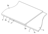
- the superposition process is a process of superposing the first metal member 1 and the second metal member 2 as shown in FIG.
- the first metal member 1 and the second metal member 2 are metal plate-like members.
- the material of the first metal member 1 and the second metal member 2 is not particularly limited as long as it is a metal capable of friction stir.
- aluminum, aluminum alloy, copper, copper alloy, titanium, titanium alloy, magnesium alloy, magnesium alloy, etc. May be selected as appropriate.
- board thickness of the 1st metal member 1 and the 2nd metal member 2 is equivalent.
- the plate thicknesses of the first metal member 1 and the second metal member 2 may be set as appropriate.
- a part of the front surface 1a of the first metal member 1 and a part of the back surface 2b of the second metal member 2 are superposed to form a superposition part J1.
- the end surface 1c on the left side of the first metal member 1 (left side with respect to the traveling direction of the joining rotary tool F (see FIG. 3)) is positioned below the back surface 2b of the second metal member 2,
- the right end surface 2 d of the second metal member 2 is positioned on the surface 1 a of the first metal member 1.
- the overlap allowance is not particularly limited, but is set to about 20 mm in this embodiment.
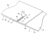
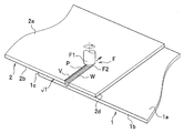
- the friction stir step is a step for friction stir welding of the overlapping portion J1 as shown in FIG.
- the joining rotary tool F rotated clockwise from the surface 2a of the second metal member 2 is inserted, and the joining rotary tool F is relatively moved along the overlapping portion J1.
- the traveling direction of the joining rotary tool F is set so that the end surface 2d of the second metal member 2 is positioned on the right side of the joining rotary tool F.
- the rotational speed of the joining rotary tool F may be set as appropriate, but is preferably 1000 to 20000 rpm, more preferably 3000 to 17500 rpm.
- the feed rate (joining speed) of the rotating tool F for joining may be set as appropriate, but is preferably 400 to 2000 mm / min, more preferably 600 to 1800 mm / min, and 1000 to 1800 mm / min. Even more preferred.
- a plasticized region W is formed on the movement locus of the welding rotary tool F. The plasticized region W is formed so as to reach the first metal member 1.
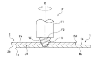
- the insertion depth of the stirring pin F2 of the joining rotary tool F may be set as appropriate, but in this embodiment, the stirring pin F2 is both the first metal member 1 and the second metal member 2. Is set to touch. By friction-stirring both the first metal member 1 and the second metal member 2, the metal of the first metal member 1 and the second metal member 2 in the vicinity of the overlapping portion J1 is plastically fluidized and joined.
- the insertion depth of the stirring pin F2 of the welding rotary tool F may be set so that the stirring pin F2 contacts only the second metal member 2. In this case, the overlapping portion J1 is plastically fluidized and joined by frictional heat between the stirring pin F2 and the second metal member 2.
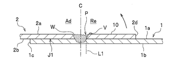
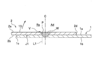
- a groove P is formed on the surface of the plasticized region W after the friction stir process, extending in the extending direction of the plasticized region W.
- the concave groove P is a deeper part and is formed on the Re side in the present embodiment.
- the Re side is the right side in the traveling direction because the welding rotary tool F is rotated to the right in this embodiment. More specifically, the Re side is a side where the magnitude of the feed speed is subtracted from the magnitude of the tangential speed on the outer periphery of the welding rotary tool F.
- the side opposite to the Re side across the joining line C is the Ad side.
- the Ad side is a side where the magnitude of the feed speed is added from the magnitude of the tangential speed on the outer periphery of the welding rotary tool F.
- the Re side of the plasticized region W in particular, the portion of the concave groove P, has a shortage of metal.
- the metal shortage on the Ad side in the plasticized region W is reduced.
- Burrs V are accumulated on the surface 2a of the second metal member 2 on the Re side.
- the burr V is continuously formed along the extending direction of the plasticized region W.
- a vertical line in the deepest portion of the groove P is a breaking line L1.
- a portion of the second metal member 2 that is closer to the end surface 2d than the break line L1 is the surplus piece portion 10.
- the surplus piece 10 is a part of the second metal member 2 that is removed from the second metal member 2 after joining.
- the rotational direction and the traveling direction of the welding rotary tool F, and the rotational speed, feed speed, and insertion depth are set so that the concave groove P and the burr V are generated on the surplus piece 10 side (Re side).
- the removing step is a step of removing the surplus piece portion 10 in which the burr V is formed in the second metal member 2.
- the surplus piece 10 of the second metal member 2 is bent in a direction away from the first metal member 1 with the concave groove P (break line L1) as a boundary.
- the surplus piece part 10 is cut
- the first metal member 1 and the second metal member 2 are joined, and the surplus piece portion in which the burr V is formed in the second metal member 2.
- the burr V can be easily removed.
- the plasticized region W the vicinity of the joining line C and the Ad side are firmly joined with little metal shortage.
- the surplus piece 10 can be removed cleanly and easily.
- the surplus piece 10 may be removed by a mechanical device or a jig, but according to the present embodiment, the surplus piece 10 can be easily removed simply by bending it manually.
- burrs V may occur at both ends in the width direction of the plasticized region W.
- the rotation direction and the traveling direction of the welding rotary tool F, as well as the number of rotations and the feed rate are such that the burr V generated on one end side (the side that becomes the surplus piece portion 10) is larger than the other end side. It is preferable to set the insertion depth. Thereby, a burr removal process can be reduced.
- the joining method according to the second embodiment of the present invention will be described. As shown in FIG. 7, the joining method according to the second embodiment is different from the first embodiment in the rotational direction of the joining rotary tool F and the like. In the description according to the second embodiment, the description will focus on parts that are different from the first embodiment.
- the friction stir step is a step of friction stir welding of the overlapping portion J1 as shown in FIG.
- the joining rotary tool F rotated counterclockwise from the surface 2a of the second metal member 2 is inserted, and the joining rotary tool F is relatively moved along the overlapping portion J1.
- the traveling direction of the joining rotary tool F is set so that the end surface 2d of the second metal member 2 is positioned on the right side of the joining rotary tool F.
- the left side in the traveling direction with respect to the joining line C is the Re side
- the right side is the Ad side
- the groove P and the burr V are formed on the Re side in the plasticized region W. Therefore, also in the second embodiment, the Re side of the second metal member 2 is the surplus piece portion 10.
- the removal step is a step of removing the surplus piece portion 10 in which the burr V is formed in the second metal member 2.
- the excess piece portion 10 of the second metal member 2 is bent in a direction away from the first metal member 1 with the groove P (break line L1) as a boundary. Thereby, the excess piece part 10 is cut
- the joining rotary tool F may be rotated counterclockwise. Even if it does in this way, the effect substantially equivalent to 1st embodiment can be acquired.
- the joining method according to the third embodiment of the present invention will be described. As shown in FIG. 9, the joining method according to the third embodiment is mainly different from the first embodiment in the overlapping process, the rotation direction of the joining rotary tool F, and the like.
- an overlapping process, a friction stirring process, and a removing process are performed.
- a part of the front surface 1a of the first metal member 1 and a part of the back surface 2b of the second metal member 2 are overlapped to form the overlapping portion J1.
- the end surface 1d on the right side of the first metal member 1 (right side with respect to the traveling direction of the bonding rotary tool F) is positioned below the back surface 2b of the second metal member 2, and the second metal member 2
- the left end surface 2c of the first metal member 1 is positioned on the surface 1a.
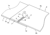
- the friction stir step is a step for friction stir welding of the overlapping portion J1 as shown in FIG.
- the joining rotary tool F rotated counterclockwise from the surface 2a of the second metal member 2 is inserted, and the joining rotary tool F is relatively moved along the overlapping portion J1.
- the traveling direction of the joining rotary tool F is set so that the end surface 2c of the second metal member 2 is positioned on the left side of the joining rotary tool F.
- the left side in the traveling direction with respect to the joining line C is the Re side
- the right side is the Ad side
- the groove P and the burr V are formed on the Re side in the plasticized region W. Therefore, also in the third embodiment, the Re side of the second metal member 2 is the surplus piece portion 10.
- the removal step is a step of removing the surplus piece portion 10 in which the burr V is formed in the second metal member 2 as shown in FIGS.
- the surplus piece 10 of the second metal member 2 is bent in a direction away from the first metal member 1 with the groove P (break line L1) as a boundary. Thereby, the excess piece part 10 is cut
- the first metal member 1 and the second metal member 2 may be overlapped so as to be different from the first embodiment.
- the rotation direction of the joining rotary tool F is opposite to that of the first embodiment. Even if it does in this way, the effect substantially equivalent to 1st embodiment can be acquired.
- the joining method according to the fourth embodiment of the present invention will be described. As shown in FIG. 11, the joining method according to the fourth embodiment is different from the third embodiment in the rotation direction of the joining rotary tool F. In the description according to the fourth embodiment, the description will focus on parts that are different from the third embodiment.
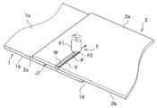
- the friction stir step is a step for friction stir welding of the overlapping portion J1 as shown in FIG.
- the joining rotary tool F rotated clockwise from the surface 2a of the second metal member 2 is inserted, and the joining rotary tool F is relatively moved along the overlapping portion J1.
- the traveling direction of the joining rotary tool F is set so that the end surface 2c of the second metal member 2 is positioned on the left side of the joining rotary tool F.
- the right side in the traveling direction with respect to the joining line C is the Re side
- the left side is the Ad side
- the concave groove P and the burr V are formed on the Re side in the plasticized region W. Therefore, also in the fourth embodiment, the Re side of the second metal member 2 is the surplus piece portion 10.
- the removal step is a step of removing the surplus piece portion 10 in which the burr V is formed in the second metal member 2 as shown in FIGS.
- the surplus piece 10 of the second metal member 2 is bent in a direction away from the first metal member 1 with the groove P (break line L1) as a boundary. Thereby, the excess piece part 10 is cut
- the joining rotary tool F may be rotated to the right. Even if it does in this way, an effect substantially equivalent to 3rd embodiment can be acquired.
- the rotational speed, feed speed, and insertion depth of the joining rotary tool F may be set so that the surplus piece 10 is removed from the second metal member 2 simultaneously with the end of the friction stirring step.
- each element is set so that the concave groove P formed in the plasticizing region W becomes large.
- the surplus piece part 10 will automatically detach
- the rotational direction, feed speed, insertion depth, first metal member 1 and the rotation direction of the rotating tool F for joining so that the concave groove P and the burr V are formed on the Re side in the plasticized region W The plate thickness and the like of the second metal member 2 are set, but the rotation direction, feed speed, and insertion depth of the rotating tool F for joining so that the concave groove P and the burr V are formed on the Ad side in the plasticized region W.
- the thickness of the first metal member 1 and the second metal member 2 may be set. In this case, the Ad side on which the burr V is formed in the second metal member 2 is the surplus piece portion 10.
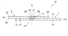
- ⁇ Tensile test 1> In tensile test 1, two types of joints were formed, and the tensile strength with respect to the feed rate (joining speed) was measured. In the tensile test 1, an A type joint X1 shown in FIG. 13 and a B type joint X2 shown in FIG. 14 were produced. The A-type joint X1 and the B-type joint X2 were both superposed on the first metal member 1 and the second metal member 2 and joined by friction stirring. The A type joint X1 was formed by the joining method according to the first embodiment described above. The B type joint X2 was formed by the joining method according to the fourth embodiment described above.
- a plurality of test specimens were prepared, each using the feed speed (joining speed) of the joining rotary tool F as a parameter.
- the feeding speed of the joining rotary tool F was set to 600, 800, 1000 mm / min.
- the rotation speed of the welding rotary tool F was set to 17500 rpm.
- Three types of thicknesses of the first metal member 1 and the second metal member 2 of 0.6, 0.7, and 0.8 mm were prepared for both the A type joint X1 and the B type joint X2.
- variety of the 1st metal member 1 and the 2nd metal member 2 was set to 50 mm and length 200mm.
- the overlap margin of the overlapping portion J1 was set to about 20 mm.
- the material of the first metal member 1 and the second metal member 2 was A3003-H16.
- A3003 Si: 0.6% or less, Fe: 0.7% or less, Cu: 0.05 to 0.20%, Mn: 1.0 to 1.5%, Zn: 0.10% or less, Others: 0.05% or less, total 0.15% or less, Al: remainder It is composed of
- line Z1 is a line indicating the tensile strength of the base material of A3003-H16 (thickness 0.6 mm) (-H16 means tempering by plastic working).
- the tensile strength of the base material of A3003-H16 is about 105 N / mm 2 .
- Line Z2 is a line indicating the tensile strength of the base material of A3003-O (thickness 0.6 mm) (-O means that annealing has been performed).
- the tensile strength of the A3003-O base material is about 70 N / mm 2 .
- the right end of the first metal member 1 and the left end of the second metal member 2 are gripped by a jig, and the first metal member 1 and the second metal member 2 are It pulled in the direction to separate, and the fracture condition was confirmed.
- the fracture line L2 is located at the end of the plasticizing region W on the Ad side.
- rupture line L2 since it fractured
- the breaking condition was confirmed.
- the breaking line L1 is a vertical line passing through the groove P. It can be seen that in the B type joint X2, when the Re side of the second metal member 2 is pulled, the groove P tends to break. Further, as shown in the result R2 of FIG. 15, it was found that the tensile strength tends to decrease as the feed rate increases.
- a type joint X1 As a result of external appearance observation and cross-sectional observation of the A type joint X1, it was found that the recess of the concave groove P on the Re side becomes deeper as the feed speed increases. On the other hand, the metal shortage on the Ad side decreased as the feed rate increased. Thereby, in A type joint X1, it is thought that the higher tensile strength (joint strength) was able to be acquired, so that feed rate became quick. Further, as shown in the result R1 of FIG. 15, the A type joint X1 can obtain a tensile strength exceeding the tensile strength (line Z2) of A3003-O when the feed speed is set to about 900 mm / min or more. all right.
- the number of rotations of the joining rotary tool F was set to 17500 rpm, and the tensile strength with respect to the feed rate (joining speed) was measured.
- eight A-type joints X1 were produced according to the feed rate by the joining method according to the first embodiment, and a tensile test was performed.
- the feed rate was set at 8 levels of 600, 800, 1000, 1200, 1400, 1600, 1800, 2000 mm / min.
- the tensile strength increases as the feed rate is increased within the feed rate range of 600 to 1200 mm / min. Further, it was found that a high tensile strength exceeding 80 N / mm 2 can be obtained within the range of the feed rate of 1000 to 1800 mm / min regardless of the feed rate. It was also found that the tensile strength was reduced at a feed rate of 2000 mm / min compared to a feed rate of 1000 to 1800 mm / min. It was found that the tensile strength exceeding the tensile strength of A3003-O (line Z2) was obtained when the feed speed of the welding rotary tool F was set to 1000 to 1800 mm / min.
- ⁇ Tensile test 3> In the tensile test 3, A-type joints X1 were produced using the rotational speed and feed rate of the joining rotary tool F as parameters, and a tensile test was performed. As shown in FIG. 17, the rotational speed of the welding rotary tool F was set to four levels of 10000, 12500, 15000, and 17500 rpm. Further, the feeding speed of the welding rotary tool F was set to four levels of 1000, 1200, and 1400 mm / min. Rotational speed of the joining rotation tool F regardless of the rotational speed is between 10000 ⁇ 17500rpm, it was found that 80 N / mm 2 about a high tensile strength is obtained.
Landscapes
- Engineering & Computer Science (AREA)
- Mechanical Engineering (AREA)
- Pressure Welding/Diffusion-Bonding (AREA)
Abstract
バリを容易に除去することができる接合方法を提供することを課題とする。攪拌ピン(F2)を備えた接合用回転ツール(F)を用いて第一金属部材(1)と第二金属部材(2)とを接合する接合方法であって、第一金属部材(1)の表面(1a)と第二金属部材(2)の裏面(2b)とを重ね合わせて重合部(J1)を形成する重ね合わせ工程と、第二金属部材(2)の表面(2a)から回転する接合用回転ツール(F)を挿入し、攪拌ピン(F2)のみを第二金属部材(2)に接触させた状態又は、第一金属部材(1)及び第二金属部材(2)の両方に接触させた状態で重合部(J1)に沿って接合用回転ツール(F)を相対移動させて摩擦攪拌接合を行う摩擦攪拌工程と、摩擦攪拌工程で形成された塑性化領域(W)を境に、第二金属部材(2)のうちバリ(V)が形成された余剰片部(10)ごと除去する除去工程と、を含むことを特徴とする。
Description
本発明は、金属部材同士を摩擦攪拌で接合する接合方法に関する。
例えば、特許文献1には、第一金属部材と第二金属部材を重ね合わせて重合部を形成した後、第二金属部材の表面から回転ツールを挿入して重合部を摩擦攪拌接合する接合方法が記載されている。当該摩擦攪拌接合では、攪拌ピンのみを第二金属部材に接触させた状態で摩擦攪拌を行うというものである。
従来の接合方法であると、回転ツールのショルダ部で塑性流動化した金属を押さえないため、塑性流動化した金属が第二金属部材の外部に溢れ出しバリが発生しやすくなる。これにより、切削装置等を用いて第二金属部材からバリを除去するバリ除去工程が煩雑になるという問題がある。
そこで、本発明は、バリを容易に除去することができる接合方法を提供することを課題とする。
前記課題を解決するために、本発明は、攪拌ピンを備えた回転ツールを用いて第一金属部材と第二金属部材とを接合する接合方法であって、前記第一金属部材の表面と前記第二金属部材の裏面とを重ね合わせて重合部を形成する重ね合わせ工程と、前記第二金属部材の表面から回転する前記回転ツールを挿入し、前記攪拌ピンのみを前記第二金属部材に接触させた状態又は、前記第一金属部材及び前記第二金属部材の両方に接触させた状態で前記重合部に沿って前記回転ツールを相対移動させて摩擦攪拌接合を行う摩擦攪拌工程と、前記摩擦攪拌工程で形成された塑性化領域を境に、前記第二金属部材のうちバリが形成された余剰片部ごと除去する除去工程と、を含むことを特徴とする。
かかる接合方法によれば、第一金属部材と第二金属部材とが接合されるとともに、第二金属部材のうちバリが形成された余剰片部ごと除去することで、バリを容易に除去することができる。
また、前記除去工程では、前記塑性化領域に形成された凹溝を境に前記余剰片部を除去することが好ましい。かかる接合方法によれば、余剰片部をきれいに除去することができる。
また、前記摩擦攪拌工程では、摩擦攪拌接合で発生するバリが前記余剰片部に形成されるように、前記回転ツールの回転方向及び進行方法を設定することが好ましい。
また、前記摩擦攪拌工程では、前記余剰片部に摩擦攪拌接合で発生するバリが形成されるように、前記回転ツールの回転数及び送り速度を設定することが好ましい。
また、前記摩擦攪拌工程では、前記余剰片部に摩擦攪拌接合で発生するバリが形成されるように、前記回転ツールの回転数及び送り速度を設定することが好ましい。
また、前記摩擦攪拌工程では、前記摩擦攪拌工程の終了と同時に前記第二金属部材から前記余剰片部が除かれるように、前記回転ツールの回転数、送り速度及び挿入深さを設定することが好ましい。かかる接合方法によれば、接合サイクルをより短くすることができる。
本発明に係る接合方法によれば、バリを容易に除去することができる。
[第一実施形態]
本発明の実施形態について図面を参照して詳細に説明する。まずは、本実施形態で用いる接合用回転ツールFについて説明する。
本発明の実施形態について図面を参照して詳細に説明する。まずは、本実施形態で用いる接合用回転ツールFについて説明する。
図1に示すように、接合用回転ツールFは、連結部F1と、攪拌ピンF2とで構成されている。接合用回転ツールFは、特許請求の範囲の「回転ツール」に相当する。接合用回転ツールFは、例えば工具鋼で形成されている。連結部F1は、摩擦攪拌装置の回転軸(図示省略)に連結される部位である。連結部F1は円柱状を呈している。
攪拌ピンF2は、連結部F1から垂下しており、連結部F1と同軸になっている。攪拌ピンF2は連結部F1から離間するにつれて先細りの円錐台形状になっている。攪拌ピンF2の外周面には螺旋溝が刻設されている。本実施形態では、接合用回転ツールFを右回転させるため、螺旋溝は、基端から先端に向かうにつれて左回りに形成されている。言い換えると、螺旋溝は、螺旋溝を基端から先端に向けてなぞると上から見て左回りに形成されている。
なお、接合用回転ツールFを左回転させる場合は、螺旋溝を基端から先端に向かうにつれて右回りに形成することが好ましい。言い換えると、この場合の螺旋溝は、螺旋溝を基端から先端に向けてなぞると上から見て右回りに形成されている。螺旋溝をこのように設定することで、摩擦攪拌の際に塑性流動化した金属が螺旋溝によって攪拌ピンF2の先端側に導かれる。これにより、被接合金属部材(後記する第一金属部材1及び第二金属部材2)の外部に溢れ出る金属の量を少なくすることができる。螺旋溝は省略してもよい。
接合用回転ツールFを用いて摩擦攪拌接合をする際には、まず、二つの被接合金属部材を重ね合わせて摩擦攪拌装置用の架台(図示省略)に載置し、治具によって被接合金属部材を固定する。次に、摩擦攪拌装置および回転ツールのうち、回転した攪拌ピンF2のみを挿入し、被接合金属部材と連結部F1とは離間させつつ移動させる。言い換えると、被接合金属部材から発生するバリ等も連結部F1に接触しないように、攪拌ピンF2の基端部は十分に露出させた状態で摩擦攪拌接合を行う。即ち、摩擦攪拌装置および回転ツールのうち、回転ツールの攪拌ピンF2のみを被接合金属部材に接触させた状態で摩擦攪拌接合を行う。
次に、本発明の第一実施形態に係る接合方法について説明する。本実施形態に係る接合方法では、重ね合わせ工程と、摩擦攪拌工程と、除去工程と、を行う。なお、下記の説明における「表面」とは、「裏面」の反対側の面という意味である。
重ね合わせ工程は、図2に示すように、第一金属部材1と第二金属部材2とを重ね合わせる工程である。第一金属部材1及び第二金属部材2は、金属製の板状部材である。第一金属部材1及び第二金属部材2の材料は、摩擦攪拌可能な金属であれば特に制限されないが、例えば、アルミニウム、アルミニウム合金、銅、銅合金、チタン、チタン合金、 マグネシウム、マグネシウム合金等から適宜選択すればよい。第一金属部材1及び第二金属部材2の板厚は同等になっている。第一金属部材1及び第二金属部材2の板厚は適宜設定すればよい。
重ね合わせ工程では、第一金属部材1の表面1aの一部と、第二金属部材2の裏面2bの一部とを重ね合わせて重合部J1を形成する。重ね合わせ工程では、第一金属部材1の左側(接合用回転ツールFの進行方向(図3参照)に対して左側)の端面1cを第二金属部材2の裏面2bの下に位置させるとともに、第二金属部材2の右側の端面2dを第一金属部材1の表面1aの上に位置させる。重ね代は特に制限されないが、本実施形態では約20mmに設定した。
摩擦攪拌工程は、図3に示すように、重合部J1を摩擦攪拌接合する工程である。摩擦攪拌工程では、第二金属部材2の表面2aから右回転させた接合用回転ツールFを挿入し、重合部J1に沿って接合用回転ツールFを相対移動させる。接合用回転ツールFの進行方向は、第二金属部材2の端面2dが接合用回転ツールFの右側に位置するように設定する。接合用回転ツールFの回転数は適宜設定すればよいが、1000~20000rpmであれば好ましく、3000~17500rpmであればより好ましい。
接合用回転ツールFの送り速度(接合速度)は、適宜設定すればよいが、400~2000mm/minであれば好ましく、600~1800mm/minであればより好ましく、1000~1800mm/minであるとさらにより好ましい。接合用回転ツールFの移動軌跡には塑性化領域Wが形成される。塑性化領域Wは、第一金属部材1に達するように形成されている。
図4に示すように、接合用回転ツールFの攪拌ピンF2の挿入深さは、適宜設定すればよいが、本実施形態では攪拌ピンF2が第一金属部材1及び第二金属部材2の両方に接触するように設定している。第一金属部材1及び第二金属部材2の両方が摩擦攪拌されることにより、重合部J1近傍の第一金属部材1及び第二金属部材2の金属が塑性流動化して接合される。なお、接合用回転ツールFの攪拌ピンF2の挿入深さは、攪拌ピンF2が第二金属部材2のみに接触するように設定してもよい。この場合は、攪拌ピンF2と第二金属部材2との摩擦熱によって重合部J1が塑性流動化して接合される。
図5に示すように、摩擦攪拌工程後の塑性化領域Wの表面には、塑性化領域Wの延長方向に亘って凹溝Pが形成される。凹溝Pは、より深くえぐられる部位であって本実施形態ではRe側に形成される。Re側とは、本実施形態では接合用回転ツールFを右回転させているため、進行方向右側となる。より詳しくは、Re側とは、接合用回転ツールFの外周における接線速度の大きさから送り速度の大きさが減算される側である。一方、接合線Cを挟んでRe側とは反対側がAd側となる。Ad側とは、接合用回転ツールFの外周における接線速度の大きさから送り速度の大きさが加算される側である。
図5に示すように、塑性化領域WのうちRe側、特に、凹溝Pの部位は金属不足が多くなっている。一方、塑性化領域WのうちAd側の金属不足は少なくなっている。Re側の第二金属部材2の表面2aにはバリVが集積されている。バリVは塑性化領域Wの延長方向に沿って連続的に形成されている。凹溝Pの最深部における鉛直方向線が破断線L1となる。本実施形態では、第二金属部材2のうち破断線L1よりも端面2d側の部位が余剰片部10となっている。余剰片部10とは、第二金属部材2のうち接合後に第二金属部材2から取り除かれる部位である。摩擦攪拌工程では、余剰片部10側(Re側)に凹溝P及びバリVが発生するように接合用回転ツールFの回転方向及び進行方向、さらには回転数、送り速度及び挿入深さを設定する。
除去工程は、図5,6に示すように、第二金属部材2のうちバリVが形成された余剰片部10ごと除去する工程である。図5に示すように、除去工程では、凹溝P(破断線L1)を境に、第二金属部材2のうち余剰片部10を第一金属部材1から離間する方向に折り曲げる。これにより、図6に示すように、凹溝P(破断線L1)を境に余剰片部10が切断される。
以上説明したように本実施形態に係る接合方法によれば、第一金属部材1と第二金属部材2とが接合されるとともに、第二金属部材2のうちバリVが形成された余剰片部10ごと除去することで、バリVを容易に除去することができる。塑性化領域Wのうち接合線C付近及びAd側は金属不足が少なく強固に接合されている。
また、塑性化領域Wに形成された凹溝Pを境に除去することにより、余剰片部10をきれいにかつ容易に除去することができる。機械装置又は治具等で余剰片部10を除去してもよいが、本実施形態によれば人手で折り曲げるだけで簡単に余剰片部10を除去することができる。
なお、摩擦攪拌工程の条件によっては、塑性化領域Wの幅方向両端にバリVが発生する場合がある。この場合は、一端側(余剰片部10となる側)に発生するバリVが、他端側よりも多くなるように接合用回転ツールFの回転方向及び進行方向、さらには回転数、送り速度及び挿入深さを設定することが好ましい。これにより、バリ除去工程を軽減することができる。
[第二実施形態]
次に、本発明の第二実施形態に係る接合方法につい説明する。第二実施形態に係る接合方法は、図7に示すように、接合用回転ツールFの回転方向等が第一実施形態と相違する。第二実施形態に係る説明では、第一実施形態と相違する部分を中心に説明する。
次に、本発明の第二実施形態に係る接合方法につい説明する。第二実施形態に係る接合方法は、図7に示すように、接合用回転ツールFの回転方向等が第一実施形態と相違する。第二実施形態に係る説明では、第一実施形態と相違する部分を中心に説明する。
第二実施形態に係る接合方法では、重ね合わせ工程と、摩擦攪拌工程と、除去工程と、を行う。重ね合わせ工程は、第一実施形態と同等なので説明を省略する。
摩擦攪拌工程は、図7に示すように、重合部J1を摩擦攪拌接合する工程である。摩擦攪拌工程では、第二金属部材2の表面2aから左回転させた接合用回転ツールFを挿入し、重合部J1に沿って接合用回転ツールFを相対移動させる。接合用回転ツールFの進行方向は、第二金属部材2の端面2dが接合用回転ツールFの右側に位置するように設定する。
図8に示すように、第二実施形態に係る摩擦攪拌工程では、接合線Cに対して進行方向左側がRe側、右側がAd側となる。本実施形態では、塑性化領域Wのうち、Re側に凹溝P及びバリVが形成されている。したがって、第二実施形態においても、第二金属部材2のうちRe側が余剰片部10となる。
除去工程は、図7,8に示すように、第二金属部材2のうちバリVが形成された余剰片部10ごと除去する工程である。図8に示すように、除去工程では、凹溝P(破断線L1)を境に、第二金属部材2のうち余剰片部10を第一金属部材1から離間する方向に折り曲げる。これにより、凹溝P(破断線L1)を境に余剰片部10が切断される。
以上説明した第二実施形態に係る接合方法のように、接合用回転ツールFを左回転させてもよい。このようにしても第一実施形態と略同等の効果を得ることができる。
[第三実施形態]
次に、本発明の第三実施形態に係る接合方法について説明する。第三実施形態に係る接合方法は、図9に示すように、主に重ね合わせ工程、接合用回転ツールFの回転方向等が第一実施形態と相違する。
次に、本発明の第三実施形態に係る接合方法について説明する。第三実施形態に係る接合方法は、図9に示すように、主に重ね合わせ工程、接合用回転ツールFの回転方向等が第一実施形態と相違する。
第三実施形態に係る接合方法では、重ね合わせ工程と、摩擦攪拌工程と、除去工程と、を行う。重ね合わせ工程では、第一金属部材1の表面1aの一部と、第二金属部材2の裏面2bの一部とを重ね合わせて重合部J1を形成する。重ね合わせ工程では、第一金属部材1の右側(接合用回転ツールFの進行方向に対して右側)の端面1dを第二金属部材2の裏面2bの下に位置させるとともに、第二金属部材2の左側の端面2cを第一金属部材1の表面1aの上に位置させる。
摩擦攪拌工程は、図9に示すように、重合部J1を摩擦攪拌接合する工程である。摩擦攪拌工程では、第二金属部材2の表面2aから左回転させた接合用回転ツールFを挿入し、重合部J1に沿って接合用回転ツールFを相対移動させる。接合用回転ツールFの進行方向は、第二金属部材2の端面2cが接合用回転ツールFの左側に位置するように設定する。
図10に示すように、第三実施形態に係る摩擦攪拌工程では、接合線Cに対して進行方向左側がRe側、右側がAd側となる。本実施形態では、塑性化領域Wのうち、Re側に凹溝P及びバリVが形成されている。したがって、第三実施形態においても、第二金属部材2のうちRe側が余剰片部10となる。
除去工程は、図9,10に示すように、第二金属部材2のうちバリVが形成された余剰片部10ごと除去する工程である。図10に示すように、除去工程では、凹溝P(破断線L1)を境に、第二金属部材2のうち余剰片部10を第一金属部材1から離間する方向に折り曲げる。これにより、凹溝P(破断線L1)を境に余剰片部10が切断される。
以上説明した第三実施形態に係る接合方法のように、第一実施形態とは異なるように第一金属部材1及び第二金属部材2を重ね合わせてもよい。第三実施形態の場合は、第一実施形態とは接合用回転ツールFの回転方向が逆となる。このようにしても第一実施形態と略同等の効果を得ることができる。
[第四実施形態]
次に、本発明の第四実施形態に係る接合方法について説明する。第四実施形態に係る接合方法は、図11に示すように、接合用回転ツールFの回転方向等が第三実施形態と相違する。第四実施形態に係る説明では、第三実施形態と相違する部分を中心に説明する。
次に、本発明の第四実施形態に係る接合方法について説明する。第四実施形態に係る接合方法は、図11に示すように、接合用回転ツールFの回転方向等が第三実施形態と相違する。第四実施形態に係る説明では、第三実施形態と相違する部分を中心に説明する。
第四実施形態に係る接合方法では、重ね合わせ工程と、摩擦攪拌工程と、除去工程と、を行う。重ね合わせ工程は、第三実施形態と同等なので説明を省略する。
摩擦攪拌工程は、図11に示すように、重合部J1を摩擦攪拌接合する工程である。摩擦攪拌工程では、第二金属部材2の表面2aから右回転させた接合用回転ツールFを挿入し、重合部J1に沿って接合用回転ツールFを相対移動させる。接合用回転ツールFの進行方向は、第二金属部材2の端面2cが接合用回転ツールFの左側に位置するように設定する。
図12に示すように、第四実施形態に係る摩擦攪拌工程では、接合線Cに対して進行方向右側がRe側、左側がAd側となる。第四実施形態では、塑性化領域Wのうち、Re側に凹溝P及びバリVが形成されている。したがって、第四実施形態においても、第二金属部材2のうちRe側が余剰片部10となる。
除去工程は、図11,12に示すように、第二金属部材2のうちバリVが形成された余剰片部10ごと除去する工程である。図12に示すように、除去工程では、凹溝P(破断線L1)を境に、第二金属部材2のうち余剰片部10を第一金属部材1から離間する方向に折り曲げる。これにより、凹溝P(破断線L1)を境に余剰片部10が切断される。
以上説明した第四実施形態に係る接合方法のように、接合用回転ツールFを右回転させてもよい。このようにしても第三実施形態と略同等の効果を得ることができる。
以上本発明の実施形態について説明したが、本発明の趣旨の範囲内において適宜設計変更が可能である。例えば、摩擦攪拌工程では、摩擦攪拌工程の終了と同時に第二金属部材2から余剰片部10が除かれるように、接合用回転ツールFの回転数、送り速度及び挿入深さを設定してもよい。つまり、この場合の摩擦攪拌工程では、塑性化領域Wに形成される凹溝Pが大きくなるように各要素を設定する。これにより、摩擦攪拌工程の終了とともに、余剰片部10が第二金属部材2から自動的に離脱する。よって、接合サイクルをより短くすることができる。
また、本実施形態では、塑性化領域WのうちRe側に凹溝P及びバリVが形成されるように接合用回転ツールFの回転方向、送り速度、挿入深さ、第一金属部材1及び第二金属部材2の板厚等を設定したが、塑性化領域WのうちAd側に凹溝P及びバリVが形成されるように接合用回転ツールFの回転方向、送り速度、挿入深さ、第一金属部材1及び第二金属部材2の板厚等を設定してもよい。この場合は、第二金属部材2のうちバリVが形成されたAd側が余剰片部10となる。
<引張り試験1>
引張り試験1では、2種類の継手を形成し、送り速度(接合速度)に対する引張強さを計測した。引張り試験1では、図13示すAタイプ継手X1と、図14に示すBタイプ継手X2とを作製した。Aタイプ継手X1及びBタイプ継手X2はいずれも第一金属部材1と第二金属部材2とを重ね合わせて摩擦攪拌により接合した。Aタイプ継手X1は、前記した第一実施形態に係る接合方法により形成した。Bタイプ継手X2は、前記した第四実施形態に係る接合方法により形成した。
引張り試験1では、2種類の継手を形成し、送り速度(接合速度)に対する引張強さを計測した。引張り試験1では、図13示すAタイプ継手X1と、図14に示すBタイプ継手X2とを作製した。Aタイプ継手X1及びBタイプ継手X2はいずれも第一金属部材1と第二金属部材2とを重ね合わせて摩擦攪拌により接合した。Aタイプ継手X1は、前記した第一実施形態に係る接合方法により形成した。Bタイプ継手X2は、前記した第四実施形態に係る接合方法により形成した。
各接合方法における摩擦攪拌工程では、接合用回転ツールFの送り速度(接合速度)をパラメータとしてそれぞれ複数個の試験体を作製した。接合用回転ツールFの送り速度は、600, 800, 1000mm/minに設定した。接合用回転ツールFの回転数は、17500rpmに設定した。Aタイプ継手X1及びBタイプ継手X2とも第一金属部材1及び第二金属部材2の厚さを0.6, 0.7, 0.8mmの三種類用意した。第一金属部材1及び第二金属部材2の幅は50mm、長さ200mmに設定した。重合部J1の重ね代は約20mmに設定した。第一金属部材1及び第二金属部材2の材料は、A3003-H16を用いた。
A3003は、Si:0.6%以下、Fe:0.7%以下、Cu:0.05~0.20%、Mn:1.0~1.5%、Zn:0.10%以下、その他:各0.05%以下、合計0.15%以下、Al:残部から構成されている。
図15に示すように、ラインZ1は、A3003-H16(厚さ0.6mm)の母材の引張強さを示す線である(-H16は塑性加工により調質を行ったことを意味する)。A3003-H16の母材の引張強さは約105N/mm2である。ラインZ2は、A3003-O(厚さ0.6mm)の母材の引張強さを示す線である(-Oは焼きなましを行ったことを意味する)。A3003-Oの母材の引張強さは約70N/mm2である。
図13に示すように、Aタイプ継手X1では、第一金属部材1の右端と、第二金属部材2の左端とを治具で把持し、第一金属部材1と第二金属部材2とが離間する方向に引張り、破断状況を確認した。Aタイプ継手X1では、いずれも破断線L2で破断した。破断線L2は、塑性化領域WのAd側の端部に位置している。Aタイプ継手X1では、破断線L2で破断したことから、塑性化領域Wによって強固に接合されていることがわかる。また、図15の結果R1に示すように、送り速度が速くなるにつれて、引張強さが高くなる傾向にあることがわかった。
一方、図14に示すように、Bタイプ継手X2では、第一金属部材1の左端と、第二金属部材2の右端を治具で把持し、第一金属部材1と第二金属部材2とが離間する方向に引張り、破断状況を確認した。Bタイプ継手X2では、いずれも破断線L1で破断した。破断線L1は、凹溝Pを通る鉛直線である。Bタイプ継手X2では、第二金属部材2のうちRe側を引っ張ると、凹溝Pで破断しやすいことがわかる。また、図15の結果R2に示すように、送り速度が速くなるにつれて、引張強さが低くなる傾向にあることがわかった。
Aタイプ継手X1の外観観察及び断面観察の結果、Re側の凹溝Pの凹みは、送り速度が速くなるにつれて深くなることがわかった。一方、Ad側の金属不足は、送り速度が速くなるほど減少した。これにより、Aタイプ継手X1では、送り速度が速くなるほど高い引張強さ(継手強度)を得ることができたと考えられる。また、図15の結果R1に示すように、Aタイプ継手X1では、送り速度を約900mm/min以上に設定するとA3003-Oの引張強さ(ラインZ2)を超える引張強さが得られることがわかった。
<引張り試験2>
引張り試験2では、接合用回転ツールFの回転数を17500rpmに設定して、送り速度(接合速度)に対する引張強さを計測した。引張り試験2では、第一実施形態に係る接合方法で、送り速度に応じて8個のAタイプ継手X1を作製し、それぞれ引張り試験を行った。送り速度は、600,800,1000,1200,1400,1600,1800,2000mm/minの8水準に設定した。
引張り試験2では、接合用回転ツールFの回転数を17500rpmに設定して、送り速度(接合速度)に対する引張強さを計測した。引張り試験2では、第一実施形態に係る接合方法で、送り速度に応じて8個のAタイプ継手X1を作製し、それぞれ引張り試験を行った。送り速度は、600,800,1000,1200,1400,1600,1800,2000mm/minの8水準に設定した。
送り速度600~1200mm/minの範囲内では、送り速度を速くするに従い引張強さも高くなることがわかった。また、送り速度1000~1800mm/minの範囲内では、送り速度に関わらず、80N/mm2を超える高い引張強さが得られることがわかった。また、送り速度が2000mm/minでは、送り速度1000~1800mm/minに比べて引張強さが低下することがわかった。接合用回転ツールFの送り速度を1000~1800mm/minに設定するとA3003-Oの引張強さ(ラインZ2)を超える引張強さになることがわかった。つまり、接合用回転ツールFの回転数や攪拌ピンF2の挿入量にもよるが、金属部材の厚さ0.6mmでは、送り速度1000~1800mm/minが好ましい送り速度の範囲であることがわかった。
<引張り試験3>
引張り試験3では、接合用回転ツールFの回転数及び送り速度をパラメータとしてそれぞれAタイプ継手X1を作製し、引張り試験を行った。図17に示すように、接合用回転ツールFの回転数を10000,12500,15000,17500rpmの4水準に設定した。また、接合用回転ツールFの送り速度を1000,1200,1400mm/minの4水準に設定した。接合用回転ツールFの回転数は10000~17500rpmの間では回転数に関わらず、80N/mm2程度の高い引張強さが得られることがわかった。
引張り試験3では、接合用回転ツールFの回転数及び送り速度をパラメータとしてそれぞれAタイプ継手X1を作製し、引張り試験を行った。図17に示すように、接合用回転ツールFの回転数を10000,12500,15000,17500rpmの4水準に設定した。また、接合用回転ツールFの送り速度を1000,1200,1400mm/minの4水準に設定した。接合用回転ツールFの回転数は10000~17500rpmの間では回転数に関わらず、80N/mm2程度の高い引張強さが得られることがわかった。
1 第一金属部材
1a 表面
1b 裏面
2 第二金属部材
2a 表面
2b 裏面
10 余剰片部
F 接合用回転ツール(回転ツール)
F1 連結部
F2 攪拌ピン
J1 重合部
P 凹溝
V バリ
W 塑性化領域
1a 表面
1b 裏面
2 第二金属部材
2a 表面
2b 裏面
10 余剰片部
F 接合用回転ツール(回転ツール)
F1 連結部
F2 攪拌ピン
J1 重合部
P 凹溝
V バリ
W 塑性化領域
Claims (5)
- 攪拌ピンを備えた回転ツールを用いて第一金属部材と第二金属部材とを接合する接合方法であって、
前記第一金属部材の表面と前記第二金属部材の裏面とを重ね合わせて重合部を形成する重ね合わせ工程と、
前記第二金属部材の表面から回転する前記回転ツールを挿入し、前記攪拌ピンのみを前記第二金属部材に接触させた状態又は、前記第一金属部材及び前記第二金属部材の両方に接触させた状態で前記重合部に沿って前記回転ツールを相対移動させて摩擦攪拌接合を行う摩擦攪拌工程と、
前記摩擦攪拌工程で形成された塑性化領域を境に、前記第二金属部材のうちバリが形成された余剰片部ごと除去する除去工程と、を含むことを特徴とする接合方法。 - 前記除去工程では、前記塑性化領域に形成された凹溝を境に前記余剰片部を除去することを特徴とする請求項1に記載の接合方法。
- 前記摩擦攪拌工程では、摩擦攪拌接合で発生するバリが前記余剰片部に形成されるように、前記回転ツールの回転方向及び進行方法を設定することを特徴とする請求項1又は請求項2に記載の接合方法。
- 前記摩擦攪拌工程では、摩擦攪拌接合で発生するバリが前記余剰片部に形成されるように、前記回転ツールの回転数及び送り速度を設定することを特徴とする請求項1に記載の接合方法。
- 前記摩擦攪拌工程では、前記摩擦攪拌工程の終了と同時に前記第二金属部材から前記余剰片部が除かれるように、前記回転ツールの回転数、送り速度及び挿入深さを設定することを特徴とする請求項1に記載の接合方法。
Priority Applications (1)
| Application Number | Priority Date | Filing Date | Title |
|---|---|---|---|
| CN201680049197.5A CN107921577B (zh) | 2015-12-16 | 2016-07-15 | 接合方法 |
Applications Claiming Priority (2)
| Application Number | Priority Date | Filing Date | Title |
|---|---|---|---|
| JP2015244727A JP6582958B2 (ja) | 2015-12-16 | 2015-12-16 | 接合方法 |
| JP2015-244727 | 2015-12-16 |
Publications (1)
| Publication Number | Publication Date |
|---|---|
| WO2017104155A1 true WO2017104155A1 (ja) | 2017-06-22 |
Family
ID=59056287
Family Applications (1)
| Application Number | Title | Priority Date | Filing Date |
|---|---|---|---|
| PCT/JP2016/071077 Ceased WO2017104155A1 (ja) | 2015-12-16 | 2016-07-15 | 接合方法 |
Country Status (3)
| Country | Link |
|---|---|
| JP (1) | JP6582958B2 (ja) |
| CN (1) | CN107921577B (ja) |
| WO (1) | WO2017104155A1 (ja) |
Families Citing this family (2)
| Publication number | Priority date | Publication date | Assignee | Title |
|---|---|---|---|---|
| JP6750562B2 (ja) * | 2017-05-26 | 2020-09-02 | 日本軽金属株式会社 | 接合方法 |
| JP6750563B2 (ja) * | 2017-05-26 | 2020-09-02 | 日本軽金属株式会社 | 接合方法 |
Citations (6)
| Publication number | Priority date | Publication date | Assignee | Title |
|---|---|---|---|---|
| JP2000141066A (ja) * | 1998-11-02 | 2000-05-23 | Unipres Corp | 接合方法 |
| JP2002035962A (ja) * | 2000-05-19 | 2002-02-05 | Kobe Steel Ltd | 重ね継手の摩擦撹拌接合方法 |
| JP2008221227A (ja) * | 2007-03-08 | 2008-09-25 | Mazda Motor Corp | 摩擦点接合構造 |
| JP2013039613A (ja) * | 2011-08-19 | 2013-02-28 | Nippon Light Metal Co Ltd | 摩擦攪拌接合方法 |
| JP2014223639A (ja) * | 2013-05-15 | 2014-12-04 | 三菱重工業株式会社 | 摩擦攪拌加工構造及び摩擦攪拌加工方法 |
| JP2015213928A (ja) * | 2014-05-08 | 2015-12-03 | 日本軽金属株式会社 | 摩擦攪拌接合方法 |
Family Cites Families (1)
| Publication number | Priority date | Publication date | Assignee | Title |
|---|---|---|---|---|
| JP2008254012A (ja) * | 2007-04-03 | 2008-10-23 | Nissan Motor Co Ltd | スポット接合装置及びスポット接合方法 |
-
2015
- 2015-12-16 JP JP2015244727A patent/JP6582958B2/ja active Active
-
2016
- 2016-07-15 CN CN201680049197.5A patent/CN107921577B/zh active Active
- 2016-07-15 WO PCT/JP2016/071077 patent/WO2017104155A1/ja not_active Ceased
Patent Citations (6)
| Publication number | Priority date | Publication date | Assignee | Title |
|---|---|---|---|---|
| JP2000141066A (ja) * | 1998-11-02 | 2000-05-23 | Unipres Corp | 接合方法 |
| JP2002035962A (ja) * | 2000-05-19 | 2002-02-05 | Kobe Steel Ltd | 重ね継手の摩擦撹拌接合方法 |
| JP2008221227A (ja) * | 2007-03-08 | 2008-09-25 | Mazda Motor Corp | 摩擦点接合構造 |
| JP2013039613A (ja) * | 2011-08-19 | 2013-02-28 | Nippon Light Metal Co Ltd | 摩擦攪拌接合方法 |
| JP2014223639A (ja) * | 2013-05-15 | 2014-12-04 | 三菱重工業株式会社 | 摩擦攪拌加工構造及び摩擦攪拌加工方法 |
| JP2015213928A (ja) * | 2014-05-08 | 2015-12-03 | 日本軽金属株式会社 | 摩擦攪拌接合方法 |
Also Published As
| Publication number | Publication date |
|---|---|
| JP6582958B2 (ja) | 2019-10-02 |
| CN107921577A (zh) | 2018-04-17 |
| CN107921577B (zh) | 2020-03-13 |
| JP2017109214A (ja) | 2017-06-22 |
Similar Documents
| Publication | Publication Date | Title |
|---|---|---|
| JP6350334B2 (ja) | 接合方法及び複合圧延材の製造方法 | |
| TWI579083B (zh) | Friction stir joining method | |
| JP5381344B2 (ja) | 接合方法 | |
| JP4190179B2 (ja) | 摩擦撹拌接合方法 | |
| JP6582958B2 (ja) | 接合方法 | |
| JP5508375B2 (ja) | 接合方法 | |
| JP6740960B2 (ja) | 接合方法 | |
| JP6756105B2 (ja) | 接合方法 | |
| CN110325314A (zh) | 接合方法 | |
| CN108472761B (zh) | 圆筒状构件的制造方法 | |
| JP6740964B2 (ja) | 接合方法 | |
| JP2018199142A (ja) | 接合方法 | |
| JP6750563B2 (ja) | 接合方法 | |
| JP5641117B2 (ja) | 接合方法 | |
| JP6662210B2 (ja) | 接合方法 | |
| JP2018020365A (ja) | 円筒状部材の製造方法 | |
| JP6756253B2 (ja) | 接合方法 | |
| JP6897024B2 (ja) | 接合方法 | |
| JP2016052666A (ja) | 接合構造体およびその製造方法、ならびに冷却器 | |
| JP2015213930A (ja) | 接合方法 | |
| JP6740963B2 (ja) | 接合方法 | |
| JP2018020363A (ja) | 接合方法 | |
| JP6702130B2 (ja) | 円筒状部材の製造方法 | |
| JP4957160B2 (ja) | 接合方法 | |
| JP2018094568A (ja) | 接合方法 |
Legal Events
| Date | Code | Title | Description |
|---|---|---|---|
| 121 | Ep: the epo has been informed by wipo that ep was designated in this application |
Ref document number: 16875142 Country of ref document: EP Kind code of ref document: A1 |
|
| NENP | Non-entry into the national phase |
Ref country code: DE |
|
| 122 | Ep: pct application non-entry in european phase |
Ref document number: 16875142 Country of ref document: EP Kind code of ref document: A1 |