WO2017104027A1 - ロボットシステム及び制御方法 - Google Patents
ロボットシステム及び制御方法 Download PDFInfo
- Publication number
- WO2017104027A1 WO2017104027A1 PCT/JP2015/085254 JP2015085254W WO2017104027A1 WO 2017104027 A1 WO2017104027 A1 WO 2017104027A1 JP 2015085254 W JP2015085254 W JP 2015085254W WO 2017104027 A1 WO2017104027 A1 WO 2017104027A1
- Authority
- WO
- WIPO (PCT)
- Prior art keywords
- robot
- fastening member
- bolt
- motor
- controller
- Prior art date
- Legal status (The legal status is an assumption and is not a legal conclusion. Google has not performed a legal analysis and makes no representation as to the accuracy of the status listed.)
- Ceased
Links
Images





Classifications
-
- B—PERFORMING OPERATIONS; TRANSPORTING
- B23—MACHINE TOOLS; METAL-WORKING NOT OTHERWISE PROVIDED FOR
- B23P—METAL-WORKING NOT OTHERWISE PROVIDED FOR; COMBINED OPERATIONS; UNIVERSAL MACHINE TOOLS
- B23P19/00—Machines for simply fitting together or separating metal parts or objects, or metal and non-metal parts, whether or not involving some deformation; Tools or devices therefor so far as not provided for in other classes
- B23P19/04—Machines for simply fitting together or separating metal parts or objects, or metal and non-metal parts, whether or not involving some deformation; Tools or devices therefor so far as not provided for in other classes for assembling or disassembling parts
- B23P19/06—Screw or nut setting or loosening machines
-
- B—PERFORMING OPERATIONS; TRANSPORTING
- B25—HAND TOOLS; PORTABLE POWER-DRIVEN TOOLS; MANIPULATORS
- B25J—MANIPULATORS; CHAMBERS PROVIDED WITH MANIPULATION DEVICES
- B25J13/00—Controls for manipulators
- B25J13/08—Controls for manipulators by means of sensing devices, e.g. viewing or touching devices
Definitions
- the present disclosure relates to a robot system and a control method.
- Patent Document 1 discloses a double-arm robot that grips a nut runner at the tip of an arm and rotates the nut runner to perform a screw tightening operation.
- an object of the present disclosure is to provide a robot system and a control method that can improve screw tightening accuracy.
- a robot system includes: a robot having a multi-joint arm; and controlling the robot to move the fastening member while rotating the fastening member having a screw portion in a loosening direction; A controller configured to perform control of the robot to rotate the fastening member in a fastening direction in response to reaching the fastening start position.
- a control method uses a robot having a multi-joint arm, controls the robot to move the fastening member while rotating the fastening member having a screw portion in a loosening direction, and the fastening member Controlling the robot to rotate the fastening member in the direction of fastening in response to reaching the screw fastening start position.
- the robot system 1 automatically performs a screw tightening operation on a workpiece W (member to be fastened).
- the screw is a fixing tool provided with a spiral groove along a surface such as a cylinder or a cone, and is a male screw having a thread formed on the outer surface or a female screw having a thread formed on the inner surface.
- the screw tightening operation is an operation of fastening a fastening member and a member to be fastened with a screw formed on at least one of them.
- the screw part is formed in both the bolt 3 that is the fastening member and the screw hole 4 of the work W that is the fastening member, and an example of fastening the bolt 3 and the work W is a screw.
- the screw hole 4 does not necessarily need to be formed in the workpiece W.
- the bolt 3 may be fastened while making a hole in the workpiece W.
- the fastening member is a bolt 3 (male screw) and the member to be fastened is a workpiece W (a screw hole 4 that is a female screw is formed).
- the fastening member is a female screw. (Nut), and the member to be fastened may be a work (male screw).
- the automatic operation of screw tightening means that at least the operation of rotating the bolt 3 for screw tightening (details will be described later) among the operations of tightening the bolt 3 to the screw hole 4 of the work W is automatically performed.
- the screw tightening operation is performed as one step when assembling an object including the workpiece W, for example.
- the robot system 1 includes a robot 2 and a controller 9 for controlling the robot 2.
- the robot 2 is a serial link type robot having a multi-joint arm 15.
- the multi-joint arm 15 includes a base 10, a turning unit 20, arms 30 (first arm) and 40 (second arm) constituting the multi-joint arm 15, a wrist 70, an end unit 80, and a motor 100.
- First motor 200 (second motor), 300 (third motor), 400, 500, 600.
- base 10 is fixed to the floor and supports the entire robot 2.
- base end means an end on the base 10 side
- tip means an end on the opposite side of the base 10.
- the turning unit 20 is provided on the base 10 and is rotatable around a vertical axis Ax1 passing through the base 10.
- a base end portion of an arm 30 is connected to the turning portion 20.
- the arm 30 is rotatable around an axis Ax2 passing through a connecting portion between the turning unit 20 and the arm 30.
- the axis Ax2 is orthogonal to the axis Ax1.
- a proximal end portion of the arm 40 is connected to the distal end portion of the arm 30.
- the arm 40 can swing around the axis Ax3 passing through the connecting portion between the arm 30 and the arm 40.
- the axis Ax3 is parallel to the axis Ax2.
- a proximal end portion of a wrist 70 is attached to the distal end portion of the arm 40.
- the distal end portion of the arm 40 and the wrist 70 can pivot around an axis Ax4 along the central axis of the arm 40.
- the wrist 70 can swing around an axis Ax5 passing through the connecting portion between the arm 40 and the wrist 70.
- the axis Ax5 is orthogonal to the axis Ax4.
- An end portion 80 is provided at the tip of the wrist 70.
- the end portion 80 can turn around the axis Ax6 along the central axis CL2 at the tip of the wrist 70.
- An end effector can be attached to the end portion 80 from the opposite side of the wrist 70.
- the end effector may be integrated with the end portion 80.
- the motor 100 generates power for turning the turning unit 20 around the axis Ax1.
- the motor 100 of FIG. 1 is provided in the turning part 20, it is not restricted to this, You may provide in the base 10.
- FIG. 1 is provided in the turning part 20, it is not restricted to this, You may provide in the base 10.
- the motor 200 generates power for swinging the arm 30 about the axis Ax2.
- the motor 200 of FIG. 1 is provided at the base end portion of the arm 30, but is not limited thereto, and may be provided at the turning portion 20.
- the motor 300 generates power for swinging the arm 40 about the axis Ax3.
- the motor 300 in FIG. 1 is provided at the proximal end portion of the arm 40, but is not limited thereto, and may be provided at the distal end portion of the arm 30.
- the motor 400 generates power for turning the arm 40 around the axis Ax4.
- the motor 400 may be provided at the proximal end portion of the arm 40, for example.
- the motor 500 generates power for swinging the wrist 70 around the axis Ax5.
- the motor 500 may be provided in the arm 40, for example.
- the motor 600 generates power for turning the end portion 80 around the axis Ax6.
- the motor 600 may be provided on the arm 40, for example.
- the robot 2 may further include a nut runner 81 (screw tightening mechanism) that can be attached to the end portion 80 of the articulated arm 15 as an example of the end effector.
- the nut runner 81 may be integrated with the end portion 80.
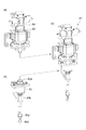
- the nut runner 81 has a base portion 82, a bit portion 83 (holding portion), and a motor 84. Details of the nut runner 81 will be described with reference to FIGS.
- the base portion 82 is detachably provided on the end portion 80 and holds the bit portion 83. In a state where the base portion 82 is attached to the end portion 80, the relative position of the base portion 82 with respect to the end portion 80 remains unchanged.
- the bit part 83 can be attached to and detached from the tip part of the base part 82 (see FIG. 2C).
- the motor 84 generates power for rotating the bolt 3 (rotating the bolt 3 with respect to the base 82).
- the motor 84 rotates the bolt 3 by applying a rotational drive to the bit portion 83 that holds the bolt 3.
- the motor 84 may be provided on the base 82, for example.
- the bit part 83 is detachable from the base part 82 and holds the bolt 3.
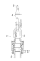
- the bit portion 83 includes a connection portion 83a, a rotation transmission portion 83b, a suction portion 83c, and a chip 83d from the proximal end side toward the distal end side.
- the connection part 83 a is a part connected to the base part 82.
- the rotation transmission unit 83b is a part that transmits torque from the motor 84 to the chip 83d.
- the suction part 83c is a part that sucks the bolt 3 toward the chip 83d by depressurizing the space around the chip 83d.
- the tip 83 d is configured to be assembled with the head of the bolt 3 and rotates together with the bolt 3. In the state in which the bolt 3 is assembled to the chip 83d, the relative position of the bolt 3 with respect to the chip 83d remains unchanged.
- the chip 83d may be anything as long as it can transmit torque to the bolt 3 in a state assembled to the head of the bolt 3.
- a plus bit inserted into the cross hole of the head of the bolt 3 a minus bit inserted into the slot (minus hole) of the head of the bolt 3, and a hexagon of the head of the bolt 3 Examples include a hexagonal bit inserted into the hole and a socket for receiving the head of the bolt 3.
- the robot 2 is configured such that the position of the bolt 3 is uniquely determined according to the posture of the robot 2. Specifically, when the robot 2 is holding the bolt 3, the distance from the connecting portion between the wrist 70 and the end portion 80, which is the most advanced joint of the articulated arm, to the bolt 3 is constant. It is comprised so that it may become. In other words, the robot 2 is configured such that the position of the bolt 3 in the coordinate system with the end portion 80 as a reference is constant.
- the nutrunner 81 does not have a buffer mechanism that varies the position of the tip 83d with respect to the base portion 82. For this reason, the position of the chip 83d with respect to the base 82 is substantially unchanged. As described above, the relative position of the base portion 82 with respect to the end portion 80 is unchanged, and the relative position of the bolt 3 with respect to the tip 83d is also unchanged. Accordingly, since the position of the tip 83d with respect to the base portion 82 is unchanged, the position of the bolt 3 in the coordinate system with respect to the end portion 80 becomes constant.
- the controller 9 controls the robot 2. Specifically, the controller 9 controls the robot 2 so that a screw tightening operation is performed on the workpiece W. That is, the controller 9 controls the robot 2 so that the bolt 3 is fastened to the screw hole 4 of the workpiece W.
- the controller 9 controls the driving of the motors 100 to 600 to set the positions and orientations of the turning unit 20, the arms 30, 40, the wrist 70, and the end unit 80. In addition, the controller 9 controls the driving of the motor 84 so as to rotate the bit unit 83 and rotate the bolt 3.
- the controller 9 controls the robot 2 to move the bolt 3 while rotating the bolt 3 having a threaded portion in reverse, and according to the bolt 3 reaching the screw hole 4 which is a screw tightening start position.
- the robot 2 is controlled to rotate the bolt 3 forward.
- the reverse rotation of the bolt 3 means that the bolt 3 is rotated in a loosening direction in the screw tightening operation.
- the normal rotation of the bolt 3 means that the bolt 3 is rotated in the tightening direction in the screw tightening operation.
- the robot system 1 may further include a console 8 as a user interface of the controller 9.
- the console 8 is connected to the controller 9, acquires input information from the user to the controller 9, and displays output information from the controller 9 to the user.
- Specific examples of the console 8 include a keyboard, a mouse, and a monitor.
- the console 8 may be a teaching pendant in which a display unit and an input unit are integrated, or may be a touch panel display.
- the controller 9 includes a search control unit 91, a tightening control unit 92, a position determination unit 93, and an attitude adjustment unit 94 as functional modules.
- the search control unit 91 controls the robot 2 to move the bolt 3 while rotating it in the reverse direction.
- the search control unit 91 controls the robot holding the bolt 3. Control by the search control unit 91 is continuously performed until the bolt 3 reaches the screw hole 4.
- the search control unit 91 performs first movement control and second movement control.
- the search control unit 91 first performs the first movement control.
- the first movement control is a process of controlling the robot 2 so that the bolt 3 set at a reference position (details will be described later) is moved along the first direction toward the workpiece W to reach the workpiece W. .
- FIG. 5A shows the bolt 3 set at the reference position.
- the first direction toward the workpiece W described above is a downward direction.
- the first direction in which the bolt 3 is moved in the first movement control may be described as the Z direction, and the directions intersecting the Z direction may be described as the X direction and the Y direction.
- the search control unit 91 performs the second movement control when the bolt 3 reaches the workpiece W at a position different from the screw hole 4 in the first movement control (see FIG. 5D).
- the second movement control is a process for controlling the robot 2 so as to move the bolt 3 by targeting a location within a predetermined range surrounding the different positions.
- the search control unit 91 repeats the second movement control until the bolt 3 reaches the screw hole 4.
- the tightening control unit 92 controls the robot 2 to rotate the bolt 3 forward as the bolt 3 reaches the screw hole 4.
- the tightening control unit 92 controls the robot 2 to rotate the bolt 3 forward and to push the bolt 3 in the direction of the screw hole 4 (see FIG. 5C).
- the tightening control unit 92 may increase the rotation speed of the bolt 3 (for example, stepwise increase) as the bolt 3 is screwed in when the bolt 3 is rotated forward.
- the tightening control unit 92 may perform a temporary tightening process in the initial stage of screwing the bolt 3 and perform a final tightening process when the screwing has advanced to a predetermined position.
- the rotational speed of the bolt 3 in the final fastening process is higher than the rotational speed of the bolt 3 in the temporary fastening process.
- the tightening control unit 92 controls the robot 2 so that the moving speed (lowering speed) of the bolt 3 increases as the screwing of the bolt 3 proceeds.
- the position determination unit 93 determines whether or not the bolt 3 has reached the screw hole 4. Based on the position (ie, height) of the bolt 3 in the direction in which the bolt 3 and the workpiece W face each other (ie, the Z direction), the position determination unit 93 determines whether the bolt 3 is in contact with the workpiece W. It may be determined whether or not the screw hole 4 has been reached.
- the position determination unit 93 may determine whether or not the bolt 3 and the workpiece W are in contact with each other based on a reaction force transmitted to the robot 2 via the bolt 3. For example, the position determination unit 93 may derive the reaction force described above based on the torque of the motors 100, 200, and 300 that are the proximal end motors in the robot 2.
- the posture adjusting unit 94 adjusts the posture of the robot 2 so as to suppress the increase in the reaction force described above.
- the posture adjustment unit 94 may adjust the posture of the robot 2 so that the reaction force does not become larger than a predetermined value, for example.
- the posture adjustment unit 94 performs the adjustment of the posture of the robot 2 by, for example, servo float control that enables tracking of an external force.
- the servo float function can be realized, for example, by providing a limit to the torque of at least one of the motors 100 to 600 (for example, the motors 100, 200, and 300).
- a limit can be provided to the torque of the motor by providing a limit to the current supplied to the motor. Note that “providing a limit” means controlling so as not to exceed the limit.
- the posture adjustment unit 94 adjusts the posture of the robot 2 with respect to the reaction force in the Z direction during the execution of the first movement control described above, in the X direction and the Y direction that intersect the Z direction. However, it does not have to be executed. That is, the posture adjustment unit 94 controls the torque of the motors 100, 200, and 300 so that the Z-direction reaction force does not exceed a predetermined value during the execution of the first movement control, and the Z-direction servo float. The function may be activated.
- the posture adjustment unit 94 adjusts the posture of the robot 2 during the execution of the second movement control described above and during the control by the tightening control unit 92, and the X force that intersects the Z direction and the reaction force in the Z direction. You may perform with respect to the reaction force of a direction and a Y direction. That is, the posture adjusting unit 94 is configured to prevent the reaction force in the Z direction, the X direction, and the Y direction from exceeding a predetermined value during the execution of the second movement control and the control by the tightening control unit 92.
- the servo float function in the Z direction, the X direction, and the Y direction may be enabled by controlling the torque of 100, 200, and 300.
- the hardware of the controller 9 is composed of, for example, one or a plurality of control computers.
- the controller 9 includes, for example, a circuit 900 illustrated in FIG. 4 as a hardware configuration.
- the circuit 900 includes a processor 901, a memory 902, a storage 903, an input / output port 904, and a driver 905.
- the driver 905 is a circuit for driving various actuators of the robot 2.
- the input / output port 904 performs input / output of signals to / from the driver 905 in addition to input / output of external signals.
- the processor 901 executes the program in consultation with at least one of the memory 902 and the storage 903, and executes input / output of signals through the input / output port 904, thereby configuring the above-described functional module.
- the hardware configuration of the controller 9 is not necessarily limited to that which constitutes a functional module by executing a program.
- the controller 9 may constitute these functional modules by a dedicated logic circuit or an ASIC (Application Specific Integrated Circuit) in which the controller 9 is integrated.
- ASIC Application Specific Integrated Circuit
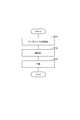
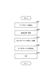
- the screw tightening process includes steps S1 to S6.
- the controller 9 first executes step S1.
- step S ⁇ b> 1 the controller 9 performs pickup control of the bolt 3.
- the controller 9 starts control of the robot 2 in response to a control start instruction.
- the control start instruction may be transmitted from a host controller or may be input by an operator via the console 8.
- the controller 9 controls the robot 2 so that the bit portion 83 of the nut runner 81 moves immediately above the bolt 3 to be fastened, and controls the robot 2 so as to operate the suction portion 83c of the bit portion 83.
- the bolt 3 is attracted to the chip 83 d side, and the chip 83 d is assembled to the head of the bolt 3.
- step S2 the controller 9 sets the bolt 3 to the reference position by moving the bit portion 83 holding the bolt 3.
- the reference position is the position of the bolt 3 when starting the first movement control by the search control unit 91.
- the reference position is aligned with the screw hole 4 of the workpiece W in the X direction and the Y direction. Therefore, the bolt 3 moved in the Z direction (downward) from the reference position by the first movement control normally reaches the screw hole 4.
- step S3 the controller 9 performs the first movement control.
- step S4 it is determined whether or not the controller 9 is at the screw tightening start position (position determination). If it is determined in step S4 that it is not the screw tightening start position, the controller 9 executes step S5. In step S5, the controller 9 performs the second movement control. If it is determined in step S4 that it is the screw tightening start position, the controller 9 executes step S6. In step S6, the controller 9 performs forward rotation control.
- the procedure of the first movement control includes steps S31 to S33.
- the posture adjustment unit 94 adjusts the posture of the robot 2 so as to suppress an increase in reaction force transmitted to the robot 2 via the bolt 3.
- the posture adjustment unit 94 controls the torque of the motors 100, 200, and 300 to enable the Z-direction servo float function so that the reaction force in the Z direction does not exceed a predetermined value.
- the posture adjustment unit 94 does not validate the servo float functions in the X direction and the Y direction.
- the attitude adjustment unit 94 may adjust the torque of the motor, for example, by adjusting the current flowing through the motor.
- the posture adjustment unit 94 may adjust the posture of the robot 2 by controlling the torque of another motor of the robot 2 instead of (or in addition to) the motors 100, 200, and 300.
- the controller 9 may execute step S31 after step S1 and before step S2. That is, the controller 9 may validate the Z-direction servo float function before setting the bolt 3 to the reference position.
- step S32 the search control unit 91 controls the robot 2 so as to reversely rotate the bolt 3.
- the reverse rotation is continuously performed until the bolt 3 reaches the screw hole 4.
- step S33 the search control unit 91 controls the robot 2 to lower the bolt 3 set at the reference position in the Z direction (downward) toward the workpiece W side. The above is the details of the first movement control in step S3.
- step S4 the position determination unit 93 determines whether or not the bolt 3 has reached the screw hole (the screw tightening start position). Based on the position (ie, height) of the bolt 3 in the direction in which the bolt 3 and the workpiece W face each other (ie, the Z direction), the position determination unit 93 determines whether the bolt 3 is in contact with the workpiece W. It may be determined whether or not the screw hole 4 has been reached.
- the position determination unit 93 may specify the height of the bolt 3 based on, for example, the value of an angular position sensor provided at the joint portion of the robot 2. For example, a rotary encoder can be used as the angular position sensor.
- the position determination unit 93 may determine whether or not the bolt 3 and the workpiece W are in contact with each other based on a reaction force transmitted to the robot 2 via the bolt 3. For example, the position determination unit 93 may derive the reaction force described above based on the torque of the motors 100, 200, and 300 that are the proximal end motors in the robot 2. When the reaction force transmitted to the robot 2 increases, it becomes necessary to overcome the reaction force and move the robot 2, so that the torque when controlling the motors 100, 200, 300 also increases. For this reason, the reaction force transmitted to the robot 2 can be detected based on the torque of the motors 100, 200, and 300.
- the position determination unit 93 may derive a reaction force based on the torque of another motor of the robot 2 instead of (or in addition to) the motors 100, 200, and 300.
- the position determination unit 93 may specify the motor torque from, for example, a current flowing through the motor. The above is the details of the position determination process in step S4.
- step S5 the procedure of the second movement control includes steps S51 to S55.
- step S51 the posture adjustment unit 94 invalidates the servo float function.
- step S52 the search control unit 91 moves the bit unit 83 holding the bolt 3 to set the bolt 3 to the reference position. That is, the search control unit 91 controls the robot 2 so that the bolt 3 is set to the reference position by moving the bolt 3 upward from the position where the bolt 3 is in contact with the workpiece W in the first control.
- the reference position is a position set in advance so as to be directly above the screw hole 4.
- the position immediately below the reference position is the screw hole. It may not be 4.
- the bolt 3 when the bolt 3 is lowered from the reference position in the first control, the bolt 3 reaches the workpiece W at a position different from the screw hole 4.
- the robot 2 is controlled so that the bolt 3 is moved by targeting a position within a predetermined range surrounding the position immediately below the reference position.
- a location within a predetermined range centered on a position immediately below the reference position may be targeted.
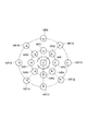
- the search control unit 91 when the position that has reached the workpiece W in the first movement control is a position MR different from the screw hole 4, the search control unit 91 has a predetermined radius centered on the different position MR.
- the eight positions NR1 to NR8 on the circumference of the circle are specified as new targets.
- the search control unit 91 determines the transition order (target order) of the positions NR1 to NR8 specified as new targets.
- step S53 the search control unit 91 controls the robot 2 so that the bolt 3 is moved immediately above the new target with the first target order.
- the search control unit 91 controls the robot 2 so as to move the bolt 3 only in the X direction and the Y direction from the reference position.
- the controller 9 may execute step S53 after step S51 without executing step S52 described above. That is, the controller 9 may move directly above the new target from the position where the bolt 3 has reached the workpiece W in the first movement control without moving to the reference position.
- step S54 the posture adjustment unit 94 controls the torques of the motors 100, 200, and 300 so that the reaction forces in the Z direction, the X direction, and the Y direction do not become larger than a predetermined value. Enable the servo float function in the X and Y directions.
- step S55 the search control unit 91 controls the robot 2 so that the bolt 3 set immediately above the new target is lowered in the Z direction (downward). The above is the details of the second movement control in step S5.
- the search control unit 91 determines that the bolt 3 has not reached the screw hole in the position determination in step S4 even if the bolt 3 is moved to the target having the first target order. In this case, the second movement control is performed again so that the bolt 3 is moved to the target having the second target order.
- the controller 9 is configured to repeat the second movement control until the bolt 3 reaches the screw hole 4. If the bolt 3 does not reach the screw hole 4 even if the bolt 3 is moved with the positions NR1 to NR8 as targets, the search control unit 91 is centered on the different position MR. Further, positions AN1 to AN8 (see FIG. 6) on the circumference of a circle having a larger radius may be specified as a new target.
- the forward rotation control procedure includes steps S61 to S69.
- step S ⁇ b> 61 the posture adjustment unit 94 activates the servo float functions in the Z direction, the X direction, and the Y direction.
- the controller 9 does not have to execute step S61 when the servo float functions in the Z direction, the X direction, and the Y direction are already enabled.
- step S62 the tightening control unit 92 controls the robot 2 so as to rotate the bolt 3 forward temporarily.
- the temporary tightening forward rotation is a forward rotation and is a forward rotation having a lower rotational speed than a final tightening forward rotation described later.
- step S63 the tightening control unit 92 controls the robot 2 to lower the bolt 3 until the torque of the motor 84 reaches a predetermined temporary tightening torque. It should be noted that the speed at which the bolt 3 is lowered during the temporary tightening forward rotation is lower than the speed at which the bolt 3 is lowered during the final tightening forward rotation described later.
- step S64 the tightening control unit 92 determines whether or not the bolt 3 has reached a predetermined temporary tightening completion position.
- the tightening control unit 92 determines whether or not the bolt 3 has reached the temporary tightening completion position based on the position (that is, the height) of the bolt 3 in the direction in which the bolt 3 and the workpiece W face each other (that is, the Z direction). You may judge.
- the tightening control unit 92 may specify the height of the bolt 3 based on, for example, a value of an angular position sensor provided at a joint portion of the robot 2.
- step S65 the tightening control unit 92 controls the robot 2 so that the bolt 3 is fully tightened and forwardly rotated.
- the final tightening forward rotation is a forward rotation and is a forward rotation having a higher rotational speed than the temporary tightening forward rotation.
- step S66 the tightening control unit 92 controls the robot 2 to lower the bolt 3 until the torque of the motor 84 reaches a predetermined final tightening torque. It should be noted that the speed at which the bolt 3 is lowered during the final tightening forward rotation is higher than the speed at which the bolt 3 is lowered during the temporary tightening forward rotation.
- step S67 the tightening control unit 92 determines whether or not the bolt 3 has reached a predetermined final tightening completion position. If it is determined in step S67 that the position is the final tightening completion position, the attitude adjustment unit 94 invalidates the servo float function (step S69), and a series of screw tightening operations are completed. On the other hand, if it is determined in step S64 that it is not the temporary tightening completion position, and if it is determined in step S67 that it is not the final tightening completion position, the tightening control unit 92 determines that the screw tightening has failed. (Step S68), the bolt 3 is loosened and removed, and the process is terminated. The above is the details of the forward rotation control in step S6.
- the robot system 1 includes the robot 2 having the articulated arm 15 and the controller 9 that controls the robot 2.
- the controller 9 controls the robot 2 to move the bolt 3 while rotating the bolt 3 having the threaded portion in the reverse direction, and rotates the bolt 3 forward according to the bolt 3 reaching the screw hole 4. In this way, the robot 2 is controlled.
- the bolt 3 is rotated in the reverse direction until the bolt 3 reaches the screw hole 4. That is, the bolt 3 rotates in the reverse direction at the stage of searching for the screw hole 4.
- the posture of the bolt 3 can be stabilized as compared with the case where the bolt 3 is not rotating. This can prevent the bolt 3 from reaching the screw hole 4 in a tilted state.
- the bolt 3 is obliquely tightened with respect to the screw hole 4 when the position of the bolt 3 is shifted with respect to the screw hole 4. Is a problem.
- the bolt 3 rotates in the reverse direction until reaching the screw hole 4, so that the bolt 3 is not tightened with respect to the screw hole 4, and oblique tightening can be suppressed.
- the posture when the bolt 3 is moved is stabilized, and the screw tightening accuracy can be improved by suppressing the oblique tightening of the bolt 3.
- the controller 9 moves the bolt 3 to the screw hole 4 (screw tightening start position). ) May be determined to have been reached.
- the bolt 3 has reached the screw hole 4 (see FIG. 5B) or not (see FIG. 5D). Since the position (height) of Z 3 in the Z direction is different, the timing of screw tightening start can be accurately detected by a simple method by determining the arrival of the screw hole 4 based on the height of the bolt 3. Can do.
- the controller 9 may be configured to determine whether or not the bolt 3 and the workpiece W are in contact based on a reaction force transmitted to the robot 2 via the bolt 3. By using the internal information of the robot 2, it is possible to accurately determine whether the bolt 3 and the workpiece W are in contact with each other with a simple configuration.
- the robot 2 has driving motors 100 to 600, and the controller 9 may derive reaction force based on torques of these motors. Since the motor torque rises according to the reaction force, it is possible to accurately determine whether the bolt 3 and the workpiece W are in contact with each other or not by deriving the reaction force based on the motor torque. .
- the controller 9 derives the reaction force based on the torques of the motor 100 for turning the turning unit 20, the motor 200 for swinging the arm 30, and the motor 300 for swinging the arm 40. May be.
- the reaction force can be detected with high sensitivity by deriving the reaction force based on the torque of the three base axes including the turning unit 20.
- the controller 9 may be configured to further execute adjustment of the posture of the robot 2 so as to suppress an increase in reaction force. Thereby, it is possible to perform screw tightening while controlling so that the force pressing the bolt 3 is not excessive, and to perform screw tightening by the robot 2 with a simple configuration that does not use a mechanical buffer mechanism such as a spring. it can.
- Controlling the robot 2 to move the bolt 3 while rotating the bolt 3 in the reverse direction controls the robot 2 to move the bolt 3 along the Z direction toward the workpiece W and reach the workpiece W.
- the bolt 3 is moved with a target within a predetermined range surrounding the position.
- the second movement control for controlling the robot 2 so that the controller 9 adjusts the posture of the robot 2 so as to suppress an increase in the reaction force during the execution of the first movement control. It is configured to execute against the reaction force in the direction and not to the reaction force in the X direction and the Y direction intersecting the Z direction, and suppresses an increase in the reaction force during execution of the second movement control.
- the posture of the robot 2 The adjusting Z direction, X-direction, and may be configured to run against the reaction force in the Y direction.
- the second movement control is performed.
- the screw hole 4 is preset so as to be arranged immediately below the reference position. Therefore, even if the first movement control fails for some reason, the screw hole 4 is located immediately below the reference position (a position different from the screw hole 4 where the bolt 3 has reached in the first movement control). It is considered that there is a high possibility of being placed. Therefore, in the second movement control, it is preferable that a location within a predetermined range surrounding the position where the bolt 3 has reached in the first movement control is targeted.
- the position of the bolt 3 reaching the workpiece W in the X direction and the Y direction may be shifted due to the torque following operation. .
- the target in the second movement control does not become the peripheral position immediately below the reference position, and the search accuracy of the screw hole 4 in the second movement control may be deteriorated.
- the reference position for setting the target in the second movement control is less likely to shift, and the screw in the second movement control The search accuracy of the hole 4 can be ensured.
- the servo float function is also enabled in the X direction and the Y direction, so that a search operation is performed in the X direction and the Y direction by the torque copying operation.
- the screw hole 4 can be searched in a wide range while shifting the position in the Y direction. That is, it is possible to easily reach the screw hole 4 in the second movement control.
- the controller 9 may be configured to repeat the second movement control until the bolt 3 reaches the screw hole 4.
- the controller 9 specifies, as new targets, positions NR1 to NR8 on the circumference having a predetermined radius centered on the position MR different from the screw hole 4 and reached in the first movement control.
- the target order is determined, and the bolt 3 is sequentially shifted to the positions NR1 to NR8 until the screw hole 4 is reached.
- the bolt 3 can reach the screw hole 4 with high probability.
- the controller 9 adjusts the posture of the robot 2 so as to suppress an increase in the reaction force.
- the controller 9 includes a motor 100 for turning the turning unit 20, a motor 200 for turning the arm 30, and the arm 40. You may comprise so that it may perform by the torque control of the motor 300 for rocking
- the controller 9 may be configured to increase the rotation speed of the bolt 3 as the bolt 3 is screwed in when the bolt 3 is rotated forward.
- the movable range of the bolt 3 in the screw hole 4 is wider in the initial stage of screwing, and oblique tightening is likely to occur due to the displacement of the bolt 3.
- oblique tightening can be suitably suppressed while the copying operation by torque control is more reliably applied.
- the later stage of screwing in which the position of the bolt 3 is generally determined, by increasing the rotational speed of the bolt 3, the screw can be fastened quickly and the working time can be shortened.
- the controller 9 may be configured to increase the rotational speed of the bolt 3 stepwise as the bolt 3 is screwed in when the bolt 3 is rotated forward.
- the temporary tightening process is performed at the initial stage of screwing, and the final tightening process higher than the rotation speed of the bolt 3 in the temporary tightening process is performed at the later stage of screwing.
- the robot 2 may be configured such that the position of the bolt 3 is uniquely determined according to the posture of the robot 2. Thereby, based on the attitude
- the robot 2 may be configured such that the distance from the most advanced joint of the multi-joint arm 15 to the bolt 3 is constant while the bolt 3 is being held. Accordingly, it is possible to simply specify the position of the bolt 3 only from the position of the robot 2, and the position of the bolt 3 can be specified with a simpler configuration.
- the robot 2 further includes a nut runner 81 that can be attached to the end portion 80, and the nut runner 81 can be attached to and detached from the end portion 80, and the bit portion that is detachable from the base portion 82 and holds the bolt 3.
- 83 and a motor 84 that rotates the bolt 3 with respect to the base portion 82, and the distance from the base portion 82 to the bolt 3 held by the bit portion 83 may be constant.
- bolt 3 does not change means that the spring mechanism, such as a spindle unit which expands / contracts in the axial direction of the volt
- the bolt 3 has reached the screw hole 4 based on the position of the bolt 3 in the direction in which the bolt 3 and the workpiece W face each other while the bolt 3 is in contact with the workpiece W. It is not limited to. That is, for example, it may be determined that the bolt 3 has reached the screw hole 4 by specifying the position of the bolt 3 with a camera or the like.
- the robot 2 has the nut runner 81 and has been described as being configured such that the distance from the base 82 of the nut runner 81 to the bolt 3 held by the bit portion 83 is constant
- the present invention is not limited to this. That is, for example, a spring mechanism is provided in the bit portion of the nut runner so that the distance from the base to the bolt is variable, and the displacement of the spring mechanism can be detected, so that the position of the bolt can be determined from the robot posture. May be determined uniquely.
- the robot 2 has the nut runner 81 and has been described as being screwed by the nut runner 81, the present invention is not limited to this, and may be screwed by other end effectors attached to the end portions.
- This disclosure can be used for screw tightening work using a robot.
Landscapes
- Engineering & Computer Science (AREA)
- Mechanical Engineering (AREA)
- Human Computer Interaction (AREA)
- Robotics (AREA)
- Manipulator (AREA)
- Automatic Assembly (AREA)
Abstract
ロボットシステム1は、多関節アームを有するロボット2と、ロボット2を制御するコントローラ9とを備える。コントローラ9は、ねじ部を有するボルト3を逆回転させながらボルト3を移動させるようにロボット2を制御することと、ボルト3がねじ穴4に到達するのに応じて、ボルト3を正回転させるようにロボット2を制御することと、を実行するように構成されている。
Description
本開示は、ロボットシステム及び制御方法に関する。
特許文献1には、アームの先端においてナットランナを把持し、該ナットランナを回転させることによりねじ締め作業を行うダブルアーム型ロボットが開示されている。
ロボットを利用したねじ締め作業において、ねじ締め精度の更なる向上が望まれる場合がある。そこで本開示は、ねじ締め精度を向上させることができるロボットシステム及び制御方法を提供することを目的とする。
本開示の一形態に係るロボットシステムは、多関節アームを有するロボットと、ねじ部を有する締結部材を緩める方向に回転させながら締結部材を移動させるようにロボットを制御することと、締結部材がねじ締め開始位置に到達するのに応じて、締結部材を締める方向に回転させるようにロボットを制御することと、を実行するように構成されたコントローラと、を備える。
本開示の一形態に係る制御方法は、多関節アームを有するロボットを用い、ねじ部を有する締結部材を緩める方向に回転させながら締結部材を移動させるようにロボットを制御することと、締結部材がねじ締め開始位置に到達するのに応じて、締結部材を締める方向に回転させるようにロボットを制御することと、を含む。
本開示によれば、ねじ締め精度を向上させることができる。
以下、実施形態について、図面を参照しつつ詳細に説明する。説明において、同一要素又は同一機能を有する要素には同一の符号を付し、重複する説明を省略する。
[ロボットシステム]
本実施形態に係るロボットシステム1は、ワークW(被締結部材)に対してねじ締め作業を自動実行するものである。ねじとは、円筒又は円錐等の面に沿って螺旋状の溝を設けた固着具であり、外表面にねじ山が形成された雄ねじ、又は、内表面にねじ山が形成された雌ねじである。ねじ締め作業とは、少なくともいずれか一方にねじが形成された締結部材及び被締結部材を締結する作業である。本実施形態では、締結部材であるボルト3、及び、被締結部材であるワークWのねじ穴4の双方にねじ部が形成されており、当該ボルト3とワークWとを締結する例を、ねじ締め作業の一例として説明する。なお、ワークWには必ずしもねじ穴4が形成されていなくてもよく、この場合、ボルト3がワークWに穴を開けながら締結されてもよい。また、本実施形態では、締結部材がボルト3(雄ねじ)であり、被締結部材がワークW(雌ねじであるねじ穴4が形成されたもの)であるとして説明するが、例えば、締結部材が雌ねじ(ナット)であり、被締結部材がワーク(雄ねじ)であってもよい。
本実施形態に係るロボットシステム1は、ワークW(被締結部材)に対してねじ締め作業を自動実行するものである。ねじとは、円筒又は円錐等の面に沿って螺旋状の溝を設けた固着具であり、外表面にねじ山が形成された雄ねじ、又は、内表面にねじ山が形成された雌ねじである。ねじ締め作業とは、少なくともいずれか一方にねじが形成された締結部材及び被締結部材を締結する作業である。本実施形態では、締結部材であるボルト3、及び、被締結部材であるワークWのねじ穴4の双方にねじ部が形成されており、当該ボルト3とワークWとを締結する例を、ねじ締め作業の一例として説明する。なお、ワークWには必ずしもねじ穴4が形成されていなくてもよく、この場合、ボルト3がワークWに穴を開けながら締結されてもよい。また、本実施形態では、締結部材がボルト3(雄ねじ)であり、被締結部材がワークW(雌ねじであるねじ穴4が形成されたもの)であるとして説明するが、例えば、締結部材が雌ねじ(ナット)であり、被締結部材がワーク(雄ねじ)であってもよい。
ねじ締め作業を自動実行するとは、ボルト3をワークWのねじ穴4に締結する作業のうち、少なくとも、ねじ締めのためにボルト3を回転させる作業(詳細は後述)を自動で実行することをいう。ねじ締め作業は、例えば、ワークWを含む物を組み立てる際の一工程として行われる。
図1に示すように、ロボットシステム1は、ロボット2と、ロボット2を制御するためのコントローラ9とを備える。
[ロボット]
(多関節アーム)
ロボット2は、多関節アーム15を有するシリアルリンク型のロボットである。以下、多関節アーム15の具体的な構成例を示す。多関節アーム15は、基台10と、旋回部20と、多関節アーム15を構成するアーム30(第1アーム),40(第2アーム)と、リスト70と、エンド部80と、モータ100(第1モータ),200(第2モータ),300(第3モータ),400,500,600とを有している。
(多関節アーム)
ロボット2は、多関節アーム15を有するシリアルリンク型のロボットである。以下、多関節アーム15の具体的な構成例を示す。多関節アーム15は、基台10と、旋回部20と、多関節アーム15を構成するアーム30(第1アーム),40(第2アーム)と、リスト70と、エンド部80と、モータ100(第1モータ),200(第2モータ),300(第3モータ),400,500,600とを有している。
基台10は床面に固定され、ロボット2全体を支持する。以下、基台10以外の各部の説明において、「基端」は基台10側の端を意味し、「先端」は基台10の逆側の端を意味する。
旋回部20は基台10上に設けられ、基台10を通る鉛直な軸線Ax1まわりに回転可能である。旋回部20にはアーム30の基端部が接続されている。
アーム30は、旋回部20とアーム30との接続部を通る軸線Ax2まわりに回転可能である。軸線Ax2は軸線Ax1に直交している。アーム30の先端部にはアーム40の基端部が接続されている。
アーム40は、アーム30とアーム40との接続部を通る軸線Ax3まわりに揺動可能である。軸線Ax3は軸線Ax2に平行である。アーム40の先端部にはリスト70の基端部が取り付けられている。アーム40の先端部及びリスト70は、アーム40の中心軸線に沿う軸線Ax4まわりに旋回可能である。
リスト70は、アーム40とリスト70との接続部を通る軸線Ax5まわりに揺動可能である。軸線Ax5は、軸線Ax4に直交している。リスト70の先端部にはエンド部80が設けられている。
エンド部80は、リスト70の先端部に中心軸線CL2に沿う軸線Ax6まわりに旋回可能である。エンド部80には、リスト70の逆側からエンドエフェクタが装着可能とされている。エンドエフェクタは、エンド部80に一体化されていてもよい。
モータ100は、軸線Ax1まわりに旋回部20を旋回させるための動力を発生する。図1のモータ100は旋回部20に設けられているが、これに限られず、基台10に設けられていてもよい。
モータ200は、軸線Ax2まわりにアーム30を揺動させるための動力を発生する。図1のモータ200はアーム30の基端部に設けられているが、これに限られず、旋回部20に設けられていてもよい。
モータ300は、軸線Ax3まわりにアーム40を揺動させるための動力を発生する。図1のモータ300はアーム40の基端部に設けられているが、これに限られず、アーム30の先端部に設けられていてもよい。
モータ400は、軸線Ax4まわりにアーム40を旋回させるための動力を発生する。モータ400は、例えばアーム40の基端部に設けられていてもよい。
モータ500は、軸線Ax5まわりにリスト70を揺動させるための動力を発生する。モータ500は、例えばアーム40に設けられていてもよい。
モータ600は、軸線Ax6まわりにエンド部80を旋回させるための動力を発生する。モータ600は、例えばアーム40に設けられていてもよい。
(ナットランナ)
ロボット2は、上記エンドエフェクタの一例として、多関節アーム15のエンド部80に装着可能なナットランナ81(ねじ締め機構)を更に有してもよい。ナットランナ81は、エンド部80に一体化されていてもよい。ナットランナ81は、基部82と、ビット部83(保持部)と、モータ84とを有している。図2及び図3も参照しながら、ナットランナ81の詳細について説明する。
ロボット2は、上記エンドエフェクタの一例として、多関節アーム15のエンド部80に装着可能なナットランナ81(ねじ締め機構)を更に有してもよい。ナットランナ81は、エンド部80に一体化されていてもよい。ナットランナ81は、基部82と、ビット部83(保持部)と、モータ84とを有している。図2及び図3も参照しながら、ナットランナ81の詳細について説明する。
基部82は、エンド部80に着脱可能に設けられており、ビット部83を保持する。基部82がエンド部80に装着された状態において、エンド部80に対する基部82の相対位置は不変となる。基部82の先端部は、ビット部83を着脱可能とされている(図2(c)参照)。モータ84は、ボルト3を回転させる(基部82に対してボルト3を回転させる)ための動力を発生する。モータ84は、ボルト3を保持するビット部83に回転駆動を与えることにより、ボルト3を回転させる。モータ84は、例えば基部82に設けられていてもよい。
ビット部83は、基部82に対して着脱可能であり、ボルト3を保持する。図3に示すように、ビット部83は、基端側から先端側に向かって、接続部83aと、回転伝達部83bと、吸着部83cと、チップ83dとを有している。接続部83aは、基部82に接続される部分である。回転伝達部83bは、モータ84からのトルクをチップ83dに伝える部分である。吸着部83cは、チップ83dのまわりの空間を減圧することにより、ボルト3をチップ83d側に吸着する部分である。チップ83dは、ボルト3の頭部に組み合うように構成されており、ボルト3と共に回転する。ボルト3がチップ83dに組み合った状態において、チップ83dに対するボルト3の相対位置は不変となる。
チップ83dは、ボルト3の頭部に組み合った状態で、ボルト3にトルクを伝達可能であればどのようなものであってもよい。チップ83dの具体例としていは、ボルト3の頭部の十字穴に挿入されるプラスビット、ボルト3の頭部のすりわり(マイナス穴)に挿入されるマイナスビット、ボルト3の頭部の六角穴に挿入される六角ビット、ボルト3の頭部を受け入れるソケット等が挙げられる。
ロボット2は、ロボット2の姿勢に対応してボルト3の位置が一義的に定まるように構成されている。具体的には、ロボット2は、ボルト3を保持している状態において、多関節アームの最先端の関節である、リスト70とエンド部80との接続部から、ボルト3までの距離が一定となるように構成されている。換言すると、ロボット2は、エンド部80を基準とした座標系におけるボルト3の位置が一定となるように構成されている。
より具体的に、ナットランナ81は、基部82に対するチップ83dの位置を変動させる緩衝機構を有していない。このため、基部82に対するチップ83dの位置は実質的に不変である。上述のように、エンド部80に対する基部82の相対位置は不変であり、チップ83dに対するボルト3の相対位置も不変である。従って、基部82に対するチップ83dの位置が不変であることで、エンド部80を基準とした座標系におけるボルト3の位置が一定となる。
[コントローラ]
コントローラ9は、ロボット2を制御する。具体的には、コントローラ9は、ワークWに対してねじ締め作業が実行されるように、ロボット2を制御する。すなわち、コントローラ9は、ワークWのねじ穴4にボルト3が締結されるように、ロボット2を制御する。
コントローラ9は、ロボット2を制御する。具体的には、コントローラ9は、ワークWに対してねじ締め作業が実行されるように、ロボット2を制御する。すなわち、コントローラ9は、ワークWのねじ穴4にボルト3が締結されるように、ロボット2を制御する。
コントローラ9は、モータ100~600の駆動を制御することにより、旋回部20、アーム30,40、リスト70、及びエンド部80の、位置及び姿勢を設定する。また、コントローラ9は、モータ84の駆動を制御することにより、ビット部83に回転駆動を与え、ボルト3を回転させる。
コントローラ9は、ねじ部を有するボルト3を逆回転させながらボルト3を移動させるようにロボット2を制御することと、ボルト3がねじ締め開始位置であるねじ穴4に到達するのに応じて、ボルト3を正回転させるようにロボット2を制御することと、を実行するように構成されている。なお、ボルト3を逆回転させるとは、ボルト3をねじ締め作業における緩める方向に回転させることをいう。また、ボルト3を正回転させるとは、ボルト3をねじ締め作業における締める方向に回転させることをいう。
ロボットシステム1は、コントローラ9のユーザインターフェースとしてコンソール8を更に備えていてもよい。コンソール8は、コントローラ9に接続されており、ユーザからコントローラ9への入力情報を取得し、コントローラ9からユーザへの出力情報を表示する。コンソール8の具体例としては、キーボード、マウス及びモニタが挙げられる。コンソール8は表示部と入力部とが一体化したティーチングペンダントであってもよいし、タッチパネルディスプレイであってもよい。
以下、コントローラ9の具体的な構成例について説明する。コントローラ9は、機能モジュールとして、探索制御部91と、締め込み制御部92と、位置判定部93と、姿勢調節部94と、を有している。
探索制御部91は、ボルト3を逆回転させながら移動させるように、ロボット2を制御する。探索制御部91は、ボルト3を保持したロボットを制御する。探索制御部91による制御は、ボルト3がねじ穴4に到達するまで継続的に行われる。探索制御部91は、第1移動制御と、第2移動制御とを行う。
探索制御部91は、最初に第1移動制御を行う。第1移動制御は、基準位置(詳細は後述)にセットされたボルト3を、ワークW側へ向かう第1方向に沿って移動させ、ワークWに到達させるようにロボット2を制御する処理である。図5(a)は基準位置にセットされたボルト3を示している。本実施形態では、ワークWの上面に形成されたねじ穴4にボルト3を締結する例を説明するため、上述したワークW側へ向かう第1方向とは下方向である。以下、第1移動制御においてボルト3を移動させる第1方向をZ方向、当該Z方向に交差する方向をX方向及びY方向として説明する場合がある。
探索制御部91は、第1移動制御においてボルト3がねじ穴4とは異なる位置でワークWに到達した場合(図5(d)参照)に、第2移動制御を行う。第2移動制御は、上記異なる位置を囲む所定の範囲内の箇所をターゲットにして、ボルト3を移動させるようにロボット2を制御する処理である。探索制御部91は、ボルト3がねじ穴4に到達するまで、第2移動制御を繰り返す。
締め込み制御部92は、ボルト3がねじ穴4に到達するのに応じて、ボルト3を正回転させるようにロボット2を制御する。締め込み制御部92は、ボルト3を正回転させると共に、ボルト3がねじ穴4の方向に押し込まれる(ねじ込まれる)ようにロボット2を制御する(図5(c)参照)。締め込み制御部92は、ボルト3を正回転させる際に、ボルト3のねじ込みが進行するのに応じてボルト3の回転速度を高く(例えば段階的に高く)してもよい。締め込み制御部92は、ボルト3のねじ込み初期段階においては仮締め処理を行い、ねじ込みが所定位置まで進んだ段階で本締め処理を行ってもよい。本締め処理におけるボルト3の回転速度は、仮締め処理におけるボルト3の回転速度よりも高い。締め込み制御部92は、ボルト3のねじ込みが進行するのに応じてボルト3の移動速度(下降速度)が高くなるようにロボット2を制御する。
位置判定部93は、ボルト3がねじ穴4に到達したか否かを判定する。位置判定部93は、ボルト3がワークWに接した状態にて、ボルト3とワークWとが対向する方向(すなわちZ方向)におけるボルト3の位置(すなわち高さ)に基づいて、ボルト3がねじ穴4に到達したか否かを判定してもよい。
位置判定部93は、ボルト3を介してロボット2に伝わる反力に基づき、ボルト3とワークWとが接しているか否かを判定してもよい。位置判定部93は、例えば、ロボット2における基端側のモータであるモータ100,200,300のトルクに基づいて、上述した反力を導出してもよい。
姿勢調節部94は、上述した反力の上昇を抑制するように、ロボット2の姿勢を調節する。姿勢調節部94は、例えば反力が所定値よりも大きくならないように、ロボット2の姿勢を調節してもよい。姿勢調節部94は、ロボット2の姿勢を調節することを、例えば、外力への追従を可能とするサーボフロート制御により実行する。サーボフロート機能は、例えば、モータ100~600の少なくとも何れか(例えばモータ100,200,300)のトルクにリミットを設けることで実現可能である。例えばモータに供給する電流にリミットを設けることで、当該モータのトルクにリミットを設けることができる。なお、「リミットを設ける」とは、当該リミットを超えないように制御することを意味する。
姿勢調節部94は、上述した第1移動制御の実行中には、ロボット2の姿勢を調節することを、Z方向の反力に対して実行し、Z方向に交差するX方向及びY方向に対しては実行しなくてもよい。すなわち、姿勢調節部94は、第1移動制御の実行中には、Z方向の反力が所定値よりも大きくならないように、モータ100,200,300のトルクを制御し、Z方向のサーボフロート機能を有効化してもよい。
姿勢調節部94は、上述した第2移動制御の実行中及び締め込み制御部92による制御中には、ロボット2の姿勢を調節することをZ方向の反力、並びに、Z方向に交差するX方向及びY方向の反力に対して実行してもよい。すなわち、姿勢調節部94は、第2移動制御の実行中及び締め込み制御部92による制御中には、Z方向、X方向、及びY方向の反力が所定値よりも大きくならないように、モータ100,200,300のトルクを制御し、Z方向、X方向、及びY方向のサーボフロート機能を有効化してもよい。
コントローラ9のハードウェアは、例えば一つ又は複数の制御用のコンピュータにより構成される。コントローラ9は、ハードウェア上の構成として、例えば図4に示す回路900を有する。回路900は、プロセッサ901と、メモリ902と、ストレージ903と、入出力ポート904と、ドライバ905とを有する。ドライバ905は、ロボット2の各種アクチュエータを駆動するための回路である。入出力ポート904は、外部信号の入出力を行うのに加え、ドライバ905に対する信号の入出力も行う。プロセッサ901は、メモリ902及びストレージ903の少なくとも一方と協議してプログラムを実行し、入出力ポート904を介した信号の入出力を実行することで、上述した機能モジュールを構成する。
なお、コントローラ9のハードウェア上の構成は、必ずしもプログラムの実行により機能モジュールを構成するものに限られない。例えばコントローラ9は、専用の論理回路により、又はこれを集積したASIC(Application Specific Integrated Circuit)によりこれらの機能モジュールを構成するものであってもよい。
[ねじ締め処理]
次に、ロボットシステム1によるねじ締め処理(制御方法)について、図7を参照して説明する。
次に、ロボットシステム1によるねじ締め処理(制御方法)について、図7を参照して説明する。
図7に示すように、ねじ締め処理の手順は、ステップS1~ステップS6を含む。コントローラ9は、まずステップS1を実行する。ステップS1では、コントローラ9が、ボルト3のピックアップ制御を行う。ピックアップ制御では、まず、制御開始指示を契機として、コントローラ9がロボット2の制御を開始する。制御開始指示は、上位のコントローラから送信されるものであってもよいし、コンソール8を介してオペレータにより入力されるものであってもよい。コントローラ9は、ナットランナ81のビット部83が、締結予定のボルト3の直上に移動するようにロボット2を制御し、ビット部83の吸着部83cを動作させるようにロボット2を制御する。これにより、ボルト3がチップ83d側に吸着され、チップ83dがボルト3の頭部に組み合う。
続いて、コントローラ9は、ステップS2を実行する。ステップS2では、コントローラ9が、ボルト3を保持したビット部83を移動させることにより、ボルト3を基準位置にセットする。基準位置とは、探索制御部91による第1移動制御を開始する際のボルト3の位置である。基準位置は、X方向及びY方向における位置がワークWのねじ穴4と一致している。そのため、第1移動制御によって基準位置からZ方向(下方向)に移動したボルト3は、通常、ねじ穴4に到達することとなる。
続いて、コントローラ9は、ステップS3を実行する。ステップS3では、コントローラ9が第1移動制御を行う。続いて、コントローラ9は、ステップS4を実行する。ステップS4では、コントローラ9がねじ締め開始位置か否かの判定(位置判定)を行う。ステップS4においてねじ締め開始位置でないと判定された場合には、コントローラ9は、ステップS5を実行する。ステップS5では、コントローラ9が第2移動制御を行う。ステップS4においてねじ締め開始位置であると判定された場合には、コントローラ9は、ステップS6を実行する。ステップS6では、コントローラ9が正回転制御を行う。以下、上述したステップS3~ステップS6の各処理の詳細について、図8~図10も参照しながら説明する。
(第1移動制御(ステップS3))
図8に示すように、第1移動制御の手順は、ステップS31~S33を含む。ステップS31では、姿勢調節部94が、ボルト3を介してロボット2に伝わる反力の上昇を抑制するようにロボット2の姿勢を調節する。姿勢調節部94は、例えば、Z方向の反力が所定値よりも大きくならないように、モータ100,200,300のトルクを制御して、Z方向のサーボフロート機能を有効化する。この場合、姿勢調節部94は、X方向及びY方向のサーボフロート機能については、有効化しない。姿勢調節部94は、例えばモータに流れる電流を調節することにより、モータのトルクを調節してもよい。なお、姿勢調節部94は、上記モータ100,200,300に替えて(又は加えて)ロボット2の他のモータのトルクを制御することにより、ロボット2の姿勢を調節してもよい。コントローラ9は、当該ステップS31を、上述したステップS1の後且つステップS2の前に実行してもよい。すなわち、コントローラ9は、ボルト3を基準位置にセットする前に、Z方向のサーボフロート機能を有効化してもよい。
図8に示すように、第1移動制御の手順は、ステップS31~S33を含む。ステップS31では、姿勢調節部94が、ボルト3を介してロボット2に伝わる反力の上昇を抑制するようにロボット2の姿勢を調節する。姿勢調節部94は、例えば、Z方向の反力が所定値よりも大きくならないように、モータ100,200,300のトルクを制御して、Z方向のサーボフロート機能を有効化する。この場合、姿勢調節部94は、X方向及びY方向のサーボフロート機能については、有効化しない。姿勢調節部94は、例えばモータに流れる電流を調節することにより、モータのトルクを調節してもよい。なお、姿勢調節部94は、上記モータ100,200,300に替えて(又は加えて)ロボット2の他のモータのトルクを制御することにより、ロボット2の姿勢を調節してもよい。コントローラ9は、当該ステップS31を、上述したステップS1の後且つステップS2の前に実行してもよい。すなわち、コントローラ9は、ボルト3を基準位置にセットする前に、Z方向のサーボフロート機能を有効化してもよい。
続いて、ステップS32では、探索制御部91が、ボルト3を逆回転させるようにロボット2を制御する。該逆回転は、ボルト3がねじ穴4に到達するまで継続的に行われる。そして、ステップS33では、探索制御部91が、基準位置にセットされたボルト3を、ワークW側へ向かうZ方向(下方向)に下降させるようにロボット2を制御する。以上が、ステップS3の第1移動制御の詳細である。
(位置判定(ステップS4))
ステップS4の位置判定では、位置判定部93が、ボルト3がねじ穴に到達したか(ねじ締め開始位置か)否かを判定する。位置判定部93は、ボルト3がワークWに接した状態にて、ボルト3とワークWとが対向する方向(すなわちZ方向)におけるボルト3の位置(すなわち高さ)に基づいて、ボルト3がねじ穴4に到達したか否かを判定してもよい。位置判定部93は、例えば、ロボット2の関節部分に設けられた角位置センサの値などに基づき、ボルト3の高さを特定してもよい。当該角位置センサとしては、例えばロータリエンコーダなどを用いることができる。
ステップS4の位置判定では、位置判定部93が、ボルト3がねじ穴に到達したか(ねじ締め開始位置か)否かを判定する。位置判定部93は、ボルト3がワークWに接した状態にて、ボルト3とワークWとが対向する方向(すなわちZ方向)におけるボルト3の位置(すなわち高さ)に基づいて、ボルト3がねじ穴4に到達したか否かを判定してもよい。位置判定部93は、例えば、ロボット2の関節部分に設けられた角位置センサの値などに基づき、ボルト3の高さを特定してもよい。当該角位置センサとしては、例えばロータリエンコーダなどを用いることができる。
図5(b)に示すように、ボルト3がワークWに接した際に、ボルト3がねじ穴4に到達していると、ボルト3がねじ穴4の先端部分に入り込む。これに対して、図5(d)に示すように、ボルト3がねじ穴4に到達しておらずボルト3がワークWにおけるねじ穴4以外に接した場合には、ボルト3がねじ穴4に入り込まない分だけ、ボルト3がねじ穴4に到達した場合よりもボルト3の高さが高くなる。このように、ボルト3がねじ穴4に到達しているか否かによって、ワークWに接した際のボルト3の高さが異なるので、位置判定部93は、ボルト3がねじ穴4に到達しているか否かを判定することができる。
位置判定部93は、ボルト3を介してロボット2に伝わる反力に基づき、ボルト3とワークWとが接しているか否かを判定してもよい。位置判定部93は、例えば、ロボット2における基端側のモータであるモータ100,200,300のトルクに基づいて、上述した反力を導出してもよい。ロボット2に伝わる反力が大きくなると、該反力に打ち勝ってロボット2を動かす必要が生じるため、モータ100,200,300を制御するときのトルクも大きくなる。このため、モータ100,200,300のトルクに基づいて、ロボット2に伝わる反力を検出することができる。なお、位置判定部93は、上記モータ100,200,300に替えて(又は加えて)ロボット2の他のモータのトルクに基づき反力を導出してもよい。位置判定部93は、例えばモータに流れる電流から、モータのトルクを特定してもよい。以上が、ステップS4の位置判定処理の詳細である。
(第2移動制御(ステップS5))
図9に示すように、第2移動制御の手順は、ステップS51~S55を含む。ステップS51では、姿勢調節部94が、サーボフロート機能を無効化する。なお、コントローラ9は、当該ステップS51を実行しなくてもよい。すなわち、コントローラ9は、サーボフロート機能を無効化しなくてもよい。続いて、ステップS52では、探索制御部91がボルト3を保持したビット部83を移動させることにより、ボルト3を基準位置にセットする。すなわち、探索制御部91は、第1制御においてボルト3がワークWに接した位置から、上方向にボルト3を移動させて基準位置にボルト3がセットされるように、ロボット2を制御する。
図9に示すように、第2移動制御の手順は、ステップS51~S55を含む。ステップS51では、姿勢調節部94が、サーボフロート機能を無効化する。なお、コントローラ9は、当該ステップS51を実行しなくてもよい。すなわち、コントローラ9は、サーボフロート機能を無効化しなくてもよい。続いて、ステップS52では、探索制御部91がボルト3を保持したビット部83を移動させることにより、ボルト3を基準位置にセットする。すなわち、探索制御部91は、第1制御においてボルト3がワークWに接した位置から、上方向にボルト3を移動させて基準位置にボルト3がセットされるように、ロボット2を制御する。
上述したように、基準位置は、ねじ穴4の直上となるように事前に設定された位置である。しかしながら、例えば、ビット部83に吸着されたボルト3が何らかの理由で傾いた場合や、ねじ穴4が形成されたワークWが何らかの理由で位置ずれした場合などにおいては、基準位置の直下がねじ穴4とならない場合がある。この場合、第1制御において基準位置からボルト3が下降すると、ボルト3はねじ穴4とは異なる位置でワークWに到達することとなる。
第2移動制御では、基準位置の直下の位置を囲む、所定の範囲内の箇所をターゲットにして、ボルト3を移動させるようにロボット2を制御する。第2移動制御では、例えば、基準位置の直下の位置を中心とした所定の範囲内の箇所がターゲットとされてもよい。
例えば、図6に示すように、第1移動制御においてワークWに到達した位置がねじ穴4とは異なる位置MRであった場合、探索制御部91は、当該異なる位置MRを中心とした所定半径の円の円周上の8つの位置NR1~NR8を新たなターゲットとして特定する。探索制御部91は、新たなターゲットとして特定した位置NR1~NR8の遷移順序(ターゲット順序)を決定する。
そして、ステップS53では、探索制御部91が、ターゲット順序が1番の新たなターゲットの直上へ、ボルト3を移動させるようにロボット2を制御する。この場合、探索制御部91は、ボルト3を、基準位置からX方向及びY方向にのみ移動させるようにロボット2を制御する。なお、コントローラ9は、上述したステップS52を実行せずに、ステップS51の後にステップS53を実行してもよい。すなわち、コントローラ9は、基準位置への移動を行わずに、第1移動制御においてボルト3がワークWに到達した位置から、新たなターゲットの直上へ直接移動してもよい。
続いて、ステップS54では、姿勢調節部94が、Z方向、X方向、及びY方向の反力が所定値よりも大きくならないように、モータ100,200,300のトルクを制御して、Z方向、X方向、及びY方向のサーボフロート機能を有効化する。更に、ステップS55では、探索制御部91が、新たなターゲットの直上にセットされたボルト3を、Z方向(下方向)に下降させるようにロボット2を制御する。以上が、ステップS5の第2移動制御の詳細である。
なお、探索制御部91は、第2移動制御において、ターゲット順序が1番のターゲットにボルト3を移動させても、ステップS4の位置判定においてボルト3がねじ穴に到達していないと判定された場合には、ターゲット順序が2番のターゲットにボルト3を移動させるように、再度、第2移動制御を行う。このように、コントローラ9は、ボルト3がねじ穴4に到達するまで第2移動制御を繰り返すように構成されている。なお、探索制御部91は、上述した位置NR1~NR8をターゲットにしてボルト3を移動させても、ボルト3がねじ穴4に到達しなかった場合には、上記異なる位置MRを中心とした、更に半径が大きい円の円周上の位置AN1~AN8(図6参照)を新たなターゲットとして特定してもよい。
(正回転制御(ステップS6))
図10に示すように、正回転制御の手順は、ステップS61~S69を含む。ステップS61では、姿勢調節部94が、Z方向、X方向、及びY方向のサーボフロート機能を有効化する。なお、コントローラ9は、すでにZ方向、X方向、及びY方向のサーボフロート機能が有効化されている場合には、ステップS61を実行しなくてもよい。続いて、ステップS62では、締め込み制御部92が、ボルト3を仮締め正回転させるようにロボット2を制御する。仮締め正回転とは、正回転であって、後述する本締め正回転よりも回転速度が低い正回転である。続いて、ステップS63では、締め込み制御部92が、モータ84のトルクが所定の仮締めトルクに到達するまで、ボルト3を下降させるようにロボット2を制御する。なお、仮締め正回転の際にボルト3を下降させる速度は、後述する本締め正回転の際にボルト3を下降させる速度よりも低い。
図10に示すように、正回転制御の手順は、ステップS61~S69を含む。ステップS61では、姿勢調節部94が、Z方向、X方向、及びY方向のサーボフロート機能を有効化する。なお、コントローラ9は、すでにZ方向、X方向、及びY方向のサーボフロート機能が有効化されている場合には、ステップS61を実行しなくてもよい。続いて、ステップS62では、締め込み制御部92が、ボルト3を仮締め正回転させるようにロボット2を制御する。仮締め正回転とは、正回転であって、後述する本締め正回転よりも回転速度が低い正回転である。続いて、ステップS63では、締め込み制御部92が、モータ84のトルクが所定の仮締めトルクに到達するまで、ボルト3を下降させるようにロボット2を制御する。なお、仮締め正回転の際にボルト3を下降させる速度は、後述する本締め正回転の際にボルト3を下降させる速度よりも低い。
ステップS64では、締め込み制御部92が、ボルト3が所定の仮締め完了位置に到達したか否かを判定する。締め込み制御部92は、ボルト3とワークWとが対向する方向(すなわちZ方向)におけるボルト3の位置(すなわち高さ)に基づいて、ボルト3が仮締め完了位置に到達したか否かを判定してもよい。締め込み制御部92は、例えば、ロボット2の関節部分に設けられた角位置センサの値などに基づき、ボルト3の高さを特定してもよい。
ステップS64において仮締め完了位置であると判定された場合には、締め込み制御部92が、ボルト3を本締め正回転させるようにロボット2を制御する(ステップS65)。本締め正回転とは、正回転であって、仮締め正回転よりも回転速度が高い正回転である。つづいて、ステップS66では、締め込み制御部92が、モータ84のトルクが所定の本締めトルクに到達するまで、ボルト3を下降させるようにロボット2を制御する。なお、本締め正回転の際にボルト3を下降させる速度は、仮締め正回転の際にボルト3を下降させる速度よりも高い。
ステップS67では、締め込み制御部92が、ボルト3が所定の本締め完了位置に到達したか否かを判定する。ステップS67において本締め完了位置であると判定された場合には、姿勢調節部94がサーボフロート機能を無効化し(ステップS69)、一連のねじ締め作業が完了する。一方で、ステップS64において仮締め完了位置でないと判定された場合、及び、ステップS67において本締め完了位置でないと判定された場合には、締め込み制御部92は、ねじ締めに失敗したと判断し(ステップS68)、ボルト3を緩めて取り出し、処理を終了する。以上が、ステップS6の正回転制御の詳細である。
[本実施形態の効果]
以上に説明したように、ロボットシステム1は、多関節アーム15を有するロボット2と、ロボット2を制御するコントローラ9とを備える。コントローラ9は、ねじ部を有するボルト3を逆回転させながらボルト3を移動させるようにロボット2を制御することと、ボルト3がねじ穴4に到達するのに応じて、ボルト3を正回転させるようにロボット2を制御することと、を実行するように構成されている。
以上に説明したように、ロボットシステム1は、多関節アーム15を有するロボット2と、ロボット2を制御するコントローラ9とを備える。コントローラ9は、ねじ部を有するボルト3を逆回転させながらボルト3を移動させるようにロボット2を制御することと、ボルト3がねじ穴4に到達するのに応じて、ボルト3を正回転させるようにロボット2を制御することと、を実行するように構成されている。
ロボットシステム1では、ボルト3がねじ穴4に到達するまで、ボルト3が逆回転させられる。すなわち、ボルト3は、ねじ穴4を探索する段階において逆回転している。ボルト3を回転させながらねじ穴4を探索することにより、ボルト3が回転していない場合と比較して、ボルト3の姿勢を安定させることができる。このことで、ボルト3が傾いた状態でねじ穴4に到達することを抑制することができる。また、例えばボルト3を正回転させながらねじ穴4を探索した場合には、ねじ穴4に対してボルト3の位置がずれていた場合に、ボルト3がねじ穴4に対して斜め締めされることが問題となる。この点、ロボットシステム1では、ねじ穴4に到達するまではボルト3が逆回転しているため、ねじ穴4に対してボルト3が締め付けられることがなく、斜め締めを抑制することができる。以上、ロボットシステム1によれば、ボルト3の移動時の姿勢が安定すると共に、ボルト3の斜め締めが抑制されることにより、ねじ締め精度を向上させることができる。
コントローラ9は、ボルト3がワークWに接した状態にて、ボルト3とワークWとが対向する方向(Z方向)におけるボルト3の位置に基づいて、ボルト3がねじ穴4(ねじ締め開始位置)に到達したと判定するように構成されていてもよい。ボルト3がワークWに接した状態において、ボルト3がねじ穴4に到達している場合(図5(b)参照)と、到達していない場合(図5(d)参照)とでは、ボルト3のZ方向の位置(高さ)が異なるので、当該ボルト3の高さに基づいてねじ穴4への到達を判定することにより、ねじ締め開始のタイミングを単純な手法で的確に検出することができる。
コントローラ9は、ボルト3を介してロボット2に伝わる反力に基づき、ボルト3とワークWとが接しているか否かを判定するように構成されていてもよい。ロボット2の内部情報を用いることにより、ボルト3とワークWとが接したか否かを単純な構成で的確に判定することができる。
ロボット2は、駆動用のモータ100~600を有し、コントローラ9はこれらのモータのトルクに基づいて、反力を導出してもよい。モータのトルクは反力に応じて上昇するので、モータのトルクに基づき反力を導出することにより、ボルト3とワークWとが接したか否かを単純な構成で的確に判定することができる。
更に、コントローラ9は、旋回部20を旋回させるためのモータ100、アーム30を揺動させるためのモータ200、及び、アーム40を揺動させるためのモータ300のトルクに基づいて、反力を導出してもよい。このように、旋回部20を含む基側の3軸のトルクに基づいて反力を導出することにより、反力を高感度に検出できる。
コントローラ9は、反力の上昇を抑制するようにロボット2の姿勢を調節することを更に実行するように構成されていてもよい。これにより、ボルト3を押し付ける力が過大とならないように制御しながらねじ締めを行うことができ、ばね等の機械的な緩衝機構を用いない簡易な構成で、ロボット2によるねじ締めを行うことができる。
ボルト3を逆回転させながらボルト3を移動させるようにロボット2を制御することは、ボルト3をワークW側へ向かうZ方向に沿って移動させ、ワークWに到達させるようにロボット2を制御する第1移動制御と、第1移動制御にて、ボルト3がねじ穴4とは異なる位置でワークWに到達した場合に、当該位置を囲む所定の範囲内の箇所をターゲットにしてボルト3を移動させるようにロボット2を制御する第2移動制御と、を含み、コントローラ9は、第1移動制御の実行中には、反力の上昇を抑制するようにロボット2の姿勢を調節することをZ方向の反力に対して実行し、Z方向に交差するX方向及びY方向の反力に対しては実行しないように構成され、第2移動制御の実行中には、反力の上昇を抑制するようにロボット2の姿勢を調節することをZ方向、X方向、及びY方向の反力に対して実行するように構成されていてもよい。
第1移動制御においてボルト3がねじ穴4とは異なる位置でワークWに到達した場合に、第2移動制御が行われる。基準位置の直下にはねじ穴4が配置されるように事前設定されている。そのため、何らかの理由により第1移動制御に失敗した場合であっても、基準位置の直下(第1移動制御においてボルト3が到達した、ねじ穴4とは異なる位置)の周辺に、ねじ穴4が配置されている可能性が高いと考えられる。よって、第2移動制御では、第1移動制御においてボルト3が到達した位置を囲む所定の範囲内の箇所がターゲットとされることが好ましい。第1移動制御において、X方向及びY方向に対してもサーボフロート機能が有効にされると、トルク倣い動作により、ワークWに到達したボルト3のX方向及びY方向における位置がずれるおそれがある。この場合には、第2移動制御におけるターゲットが、基準位置の直下の周辺位置とならず、第2移動制御におけるねじ穴4の探索精度を悪化させるおそれがある。この点、第1移動制御において、Z方向のサーボフロート機能のみが有効にされることにより、第2移動制御におけるターゲットを設定する際の基準となる位置がずれにくくなり、第2移動制御におけるねじ穴4の探索精度を担保することができる。一方で、第2移動制御においては、X方向及びY方向に対してもサーボフロート機能が有効にされることにより、トルク倣い動作によって、X方向及びY方向に探り動作が行われ、X方向及びY方向における位置をずらしながら、広範囲でねじ穴4を探索することができる。すなわち、第2移動制御においてねじ穴4に到達し易くすることができる。
コントローラ9は、ボルト3がねじ穴4に到達するまで第2移動制御を繰り返すように構成されていてもよい。コントローラ9は、例えば図6に示すように、第1移動制御において到達した、ねじ穴4とは異なる位置MRを中心とした所定半径の円周上の位置NR1~NR8を新たなターゲットとして特定し、ターゲット順序を決めて、ねじ穴4に到達するまで、位置NR1~NR8へボルト3を順次遷移させる。このように新たなターゲットへのボルト3の遷移を繰り返すことにより、ボルト3を高確率でねじ穴4に到達させることができる。
コントローラ9は、反力の上昇を抑制するようにロボット2の姿勢を調整することを、旋回部20を旋回させるためのモータ100、アーム30を揺動させるためのモータ200、及び、アーム40を揺動させるためのモータ300のトルク制御により実行するように構成されていてもよい。旋回部20を含む基側の3軸のトルク制御を行うことにより、反力に対する応答性を高めることができる。
コントローラ9は、ボルト3を正回転させる際に、ボルト3のねじ込みが進行するのに応じてボルト3の回転速度を高くするように構成されていてもよい。ボルト3をねじ穴4にねじ込む際においては、ねじ込みの初期段階ほど、ねじ穴4におけるボルト3の可動範囲が広く、ボルト3の位置ずれにより斜め締めが発生しやすい。この点、初期段階においては、ボルト3の回転速度を低くすることにより、トルク制御による倣い動作をより確実に作用させながら、斜め締めを好適に抑制することができる。一方で、ボルト3の位置が概ね定まっているねじ込みの後期段階においては、ボルト3の回転速度を高くすることにより、迅速にねじ締めを行い、作業時間を短縮することができる。
コントローラ9は、ボルト3を正回転させる際に、ボルト3のねじ込みが進行するのに応じて、ボルト3の回転速度を段階的に高くするように構成されていてもよい。具体的には、本実施形態では、ねじ込みの初期段階では仮締め処理が行われ、ねじ込みの後期段階では仮締め処理におけるボルト3の回転速度よりも高い本締め処理が行われる。回転速度を段階的に高くすることにより、ねじ込みの進行に応じた回転速度の変更を簡易且つ適切に行うことができる。
ロボット2は、ロボット2の姿勢に対応してボルト3の位置が一義的に定まるように構成されていてもよい。これにより、ロボット2の姿勢に基づいて、ボルト3の位置を簡易且つ高精度に特定することができる。
ロボット2は、ボルト3を保持している状態において、多関節アーム15の最先端の関節からボルト3までの距離が一定となるように構成されていてもよい。これによって、単純に、ロボット2の位置のみからボルト3の位置を特定することが可能となり、より簡易な構成で、ボルト3の位置を特定することができる。
ロボット2は、エンド部80に装着可能なナットランナ81を更に有し、ナットランナ81は、エンド部80に着脱可能な基部82と、基部82に対して着脱可能であり、ボルト3を保持するビット部83と、ボルト3を基部82に対して回転させるモータ84とを有し、基部82から、ビット部83により保持されたボルト3までの距離が一定となるように構成されていてもよい。ナットランナ81を用いることにより、ロボット2によるねじ締めを簡易且つ適切に行うことができる。また、ナットランナ81を用いてねじ締めを行う際において、基部82からボルト3までの長さが変わらないので、単純に、ロボット2の位置のみからボルト3の位置を特定することが可能となり、簡易な構成で、ボルト3の位置を特定することができる。
なお、基部82からボルト3までの長さが不変になるとは、ビット部83において、ボルト3の軸方向に伸縮するスピンドルユニット等のばね機構が設けられていないことを意味している。ばね機構が設けられていないことにより、ばね機構が設けられた場合と比較して、ボルト3とねじ穴4のねじ山同士の不完全な噛み込みが発生し易くなることが考えられる。この点、本実施形態では、上述したようにボルト3が逆回転しているので、ばね機構を用いず基部82からボルト3までの長さを不変とした場合においても、ねじ山同士の不完全な噛み込みが発生することを抑制できる。
以上、実施形態について説明したが、本発明は必ずしも上述した実施形態に限定されるものではなく、その要旨を逸脱しない範囲で様々な変更が可能である。
例えば、ボルト3がワークWに接した状態にて、ボルト3とワークWとが対向する方向におけるボルト3の位置に基づいて、ボルト3がねじ穴4に到達したと判定するとして説明したがこれに限定されない。すなわち、例えば、カメラ等によってボルト3の位置を特定することにより、ボルト3がねじ穴4に到達したことを判定してもよい。
また、ロボット2はナットランナ81を有し、ナットランナ81の基部82からビット部83により保持されたボルト3までの距離が一定となるように構成されているとして説明したがこれに限定されない。すなわち、例えばナットランナのビット部にばね機構が設けられ、基部からボルトまでの距離が可変とされると共に、ばね機構の変位量を検出可能な構成を更に備えることによって、ロボットの姿勢からボルトの位置が一義的に定まるように構成されていてもよい。
また、ロボット2はナットランナ81を有し、該ナットランナ81によりねじ締めを行うとして説明したがこれに限定されず、エンド部に装着したその他のエンドエフェクタにより、ねじ締めを行ってもよい。
本開示は、ロボットを利用したねじ締め作業に利用可能である。
1…ロボットシステム、2…ロボット、3…ボルト(締結部材)、4…ねじ穴、9…コントローラ、15…多関節アーム、20…旋回部、30,40…アーム(第1アーム及び第2アーム)、80…エンド部(先端部)、81…ナットランナ(ねじ締め機構)、82…基部、83…ビット部(保持部)、100,200,300…モータ(第1モータ、第2モータ、及び第3モータ)、W…ワーク(被締結部材)。
Claims (15)
- 多関節アームを有するロボットと、
ねじ部を有する締結部材を緩める方向に回転させながら前記締結部材を移動させるように前記ロボットを制御することと、前記締結部材がねじ締め開始位置に到達するのに応じて、前記締結部材を締める方向に回転させるように前記ロボットを制御することと、を実行するように構成されたコントローラと、を備えるロボットシステム。 - 前記コントローラは、前記締結部材が被締結部材に接した状態にて、前記締結部材と前記被締結部材とが対向する方向における前記締結部材の位置に基づいて、前記締結部材が前記ねじ締め開始位置に到達したと判定するように構成されている、請求項1記載のロボットシステム。
- 前記コントローラは、前記締結部材を介して前記ロボットに伝わる反力に基づき、前記締結部材と前記被締結部材とが接しているか否かを判定することを更に実行するように構成されている、請求項2記載のロボットシステム。
- 前記ロボットは、少なくとも1つの駆動用のモータを有し、
前記コントローラは、前記モータのトルクに基づいて、前記反力を導出する、請求項3記載のロボットシステム。 - 前記コントローラは、前記反力の上昇を抑制するように前記ロボットの姿勢を調節することを更に実行するように構成されている、請求項4記載のロボットシステム。
- 前記締結部材を緩める方向に回転させながら前記締結部材を移動させるように前記ロボットを制御することは、
前記締結部材を前記被締結部材側へ向かう第1方向に沿って移動させ、前記被締結部材に到達させるように前記ロボットを制御する第1移動制御と、
前記第1移動制御にて、前記締結部材が前記ねじ締め開始位置とは異なる位置で前記被締結部材に到達した場合に、当該位置を囲む所定の範囲内の箇所をターゲットにして前記締結部材を移動させるように前記ロボットを制御する第2移動制御と、を含み、
前記コントローラは、
前記第1移動制御の実行中には、前記反力の上昇を抑制するように前記ロボットの姿勢を調節することを前記第1方向の反力に対して実行し、前記第1方向に交差する方向の反力に対しては実行しないように構成され、
前記第2移動制御の実行中には、前記反力の上昇を抑制するように前記ロボットの姿勢を調節することを前記第1方向の反力、及び前記第1方向に交差する方向の反力に対して実行するように構成されている、請求項5記載のロボットシステム。 - 前記コントローラは、前記締結部材が前記ねじ締め開始位置に到達するまで前記第2移動制御を繰り返すように構成されている、請求項6記載のロボットシステム。
- 前記ロボットは、旋回部と、前記旋回部に対して直列に接続された第1アーム及び第2アームと、前記旋回部を旋回させるための第1モータと、前記第1アームを揺動させるための第2モータと、前記第2アームを揺動させるための第3モータと、を有し、
前記コントローラは、前記反力の上昇を抑制するように前記ロボットの姿勢を調節することを、前記第1モータ、前記第2モータ、及び前記第3モータのトルク制御により実行するように構成されている、請求項5~7のいずれか一項記載のロボットシステム。 - 前記ロボットは、旋回部と、前記旋回部に対して直列に接続された第1アーム及び第2アームと、前記旋回部を旋回させるための第1モータと、前記第1アームを揺動させるための第2モータと、前記第2アームを揺動させるための第3モータと、を有し、
前記コントローラは、前記第1モータ、前記第2モータ、及び前記第3モータのトルクに基づいて、前記反力を導出する、請求項4~8のいずれか一項記載のロボットシステム。 - 前記コントローラは、前記締結部材を締める方向に回転させる際に、前記締結部材のねじ込みが進行するのに応じて前記締結部材の回転速度を高くするように構成されている、請求項5~8のいずれか一項記載のロボットシステム。
- 前記コントローラは、前記締結部材を締める方向に回転させる際に、前記締結部材のねじ込みが進行するのに応じて前記締結部材の回転速度を段階的に高くするように構成されている、請求項10記載のロボットシステム。
- 前記ロボットは、前記ロボットの姿勢に対応して前記締結部材の位置が一義的に定まるように構成されている、請求項2~11のいずれか一項記載のロボットシステム。
- 前記ロボットは、前記締結部材を保持している状態において、前記多関節アームの最先端の関節から前記締結部材までの距離が一定となるように構成されている、請求項12記載のロボットシステム。
- 前記ロボットは、前記多関節アームの先端部に装着可能なねじ締め機構を更に有し、
前記ねじ締め機構は、
前記先端部に着脱可能な基部と、前記基部に対して着脱可能であり、前記締結部材を保持する保持部と、当該締結部材を前記基部に対して回転させるモータとを有し、
前記基部から、前記保持部により保持された前記締結部材までの距離が一定となるように構成されている、請求項13記載のロボットシステム。 - 多関節アームを有するロボットを用い、
ねじ部を有する締結部材を緩める方向に回転させながら前記締結部材を移動させるように前記ロボットを制御することと、
前記締結部材がねじ締め開始位置に到達するのに応じて、前記締結部材を締める方向に回転させるように前記ロボットを制御することと、を含む制御方法。
Priority Applications (3)
| Application Number | Priority Date | Filing Date | Title |
|---|---|---|---|
| CN201580084584.8A CN108290257B (zh) | 2015-12-16 | 2015-12-16 | 机器人系统以及控制方法 |
| JP2017555930A JP6575607B2 (ja) | 2015-12-16 | 2015-12-16 | ロボットシステム及び制御方法 |
| PCT/JP2015/085254 WO2017104027A1 (ja) | 2015-12-16 | 2015-12-16 | ロボットシステム及び制御方法 |
Applications Claiming Priority (1)
| Application Number | Priority Date | Filing Date | Title |
|---|---|---|---|
| PCT/JP2015/085254 WO2017104027A1 (ja) | 2015-12-16 | 2015-12-16 | ロボットシステム及び制御方法 |
Publications (1)
| Publication Number | Publication Date |
|---|---|
| WO2017104027A1 true WO2017104027A1 (ja) | 2017-06-22 |
Family
ID=59056132
Family Applications (1)
| Application Number | Title | Priority Date | Filing Date |
|---|---|---|---|
| PCT/JP2015/085254 Ceased WO2017104027A1 (ja) | 2015-12-16 | 2015-12-16 | ロボットシステム及び制御方法 |
Country Status (3)
| Country | Link |
|---|---|
| JP (1) | JP6575607B2 (ja) |
| CN (1) | CN108290257B (ja) |
| WO (1) | WO2017104027A1 (ja) |
Cited By (10)
| Publication number | Priority date | Publication date | Assignee | Title |
|---|---|---|---|---|
| CN108356508A (zh) * | 2018-02-08 | 2018-08-03 | 广东利迅达机器人系统股份有限公司 | 驱动器控制板的自动化装配设备 |
| JP2019025567A (ja) * | 2017-07-27 | 2019-02-21 | 川崎重工業株式会社 | ロボットを用いたネジ締め方法及びネジ締め用ロボット |
| CN110216464A (zh) * | 2019-07-15 | 2019-09-10 | 昆山瑞航自动化设备科技有限公司 | 一种三轴定位螺丝锁紧机构 |
| JP2019210684A (ja) * | 2018-06-04 | 2019-12-12 | 清水建設株式会社 | エンドエフェクタおよび部材取り付け方法 |
| JPWO2022138380A1 (ja) * | 2020-12-22 | 2022-06-30 | ||
| CN115555612A (zh) * | 2022-08-25 | 2023-01-03 | 中国航空制造技术研究院 | 一种用于微群孔加工的专用装置 |
| CN116765774A (zh) * | 2023-06-25 | 2023-09-19 | 北京新风航天装备有限公司 | 一种双机器人协同的钢丝螺套自动安装方法 |
| CN117381394A (zh) * | 2023-10-31 | 2024-01-12 | 小鹏汽车华中(武汉)有限公司 | 紧固系统的控制方法、可读存储介质及紧固系统 |
| WO2025225302A1 (ja) * | 2024-04-23 | 2025-10-30 | パナソニック株式会社 | 電動工具及び電動工具システム |
| TWI914448B (zh) | 2020-12-22 | 2026-02-11 | 日商發那科股份有限公司 | 螺絲鎖附系統 |
Families Citing this family (5)
| Publication number | Priority date | Publication date | Assignee | Title |
|---|---|---|---|---|
| CN109318238B (zh) * | 2018-08-15 | 2022-06-17 | 南阳师范学院 | 一种火灾阀门关闭消防机器人 |
| JP7260002B2 (ja) * | 2020-01-16 | 2023-04-18 | オムロン株式会社 | 制御装置、制御方法、及び制御プログラム |
| CN112171251A (zh) * | 2020-09-07 | 2021-01-05 | 唐根添 | 一种螺栓拧紧机及其使用方法 |
| JP7363755B2 (ja) * | 2020-12-15 | 2023-10-18 | 株式会社ダイフク | ねじ部材締緩装置、及びねじ部材締緩方法 |
| CN116237739A (zh) * | 2022-12-01 | 2023-06-09 | 上海非夕机器人科技有限公司 | 拧螺丝的方法、装置、机器人和存储介质 |
Citations (3)
| Publication number | Priority date | Publication date | Assignee | Title |
|---|---|---|---|---|
| JPH07214432A (ja) * | 1994-01-31 | 1995-08-15 | Sanyo Electric Co Ltd | ネジ締めロボット |
| JP2006142415A (ja) * | 2004-11-17 | 2006-06-08 | Honda Motor Co Ltd | 螺子部材供給締付装置 |
| JP2006315097A (ja) * | 2005-05-10 | 2006-11-24 | Toyota Motor Corp | ねじ締付装置及びねじ締付方法 |
Family Cites Families (8)
| Publication number | Priority date | Publication date | Assignee | Title |
|---|---|---|---|---|
| JPH07223130A (ja) * | 1994-02-08 | 1995-08-22 | Nippondenso Co Ltd | ねじ締め装置 |
| JPH1142519A (ja) * | 1997-07-30 | 1999-02-16 | Mitsubishi Electric Corp | 廃家電品のネジ除去装置 |
| JP2001162459A (ja) * | 1999-12-10 | 2001-06-19 | Nitto Seiko Co Ltd | 自動ねじ締め機 |
| JP4563462B2 (ja) * | 2008-03-10 | 2010-10-13 | 本田技研工業株式会社 | ボルト取り外し方法 |
| JP5237056B2 (ja) * | 2008-11-10 | 2013-07-17 | 本田技研工業株式会社 | ドア取り外しシステムおよびドア取り外し方法 |
| JP5741617B2 (ja) * | 2013-03-19 | 2015-07-01 | 株式会社安川電機 | ロボット装置 |
| JP6182756B2 (ja) * | 2013-07-05 | 2017-08-23 | 富士通周辺機株式会社 | ねじ緩め装置 |
| JP6045465B2 (ja) * | 2013-09-19 | 2016-12-14 | 三菱電機株式会社 | ねじ締め装置及びねじ締め方法 |
-
2015
- 2015-12-16 CN CN201580084584.8A patent/CN108290257B/zh active Active
- 2015-12-16 WO PCT/JP2015/085254 patent/WO2017104027A1/ja not_active Ceased
- 2015-12-16 JP JP2017555930A patent/JP6575607B2/ja active Active
Patent Citations (3)
| Publication number | Priority date | Publication date | Assignee | Title |
|---|---|---|---|---|
| JPH07214432A (ja) * | 1994-01-31 | 1995-08-15 | Sanyo Electric Co Ltd | ネジ締めロボット |
| JP2006142415A (ja) * | 2004-11-17 | 2006-06-08 | Honda Motor Co Ltd | 螺子部材供給締付装置 |
| JP2006315097A (ja) * | 2005-05-10 | 2006-11-24 | Toyota Motor Corp | ねじ締付装置及びねじ締付方法 |
Cited By (19)
| Publication number | Priority date | Publication date | Assignee | Title |
|---|---|---|---|---|
| JP2019025567A (ja) * | 2017-07-27 | 2019-02-21 | 川崎重工業株式会社 | ロボットを用いたネジ締め方法及びネジ締め用ロボット |
| CN108356508B (zh) * | 2018-02-08 | 2019-10-18 | 广东利迅达机器人系统股份有限公司 | 驱动器控制板的自动化装配设备 |
| CN108356508A (zh) * | 2018-02-08 | 2018-08-03 | 广东利迅达机器人系统股份有限公司 | 驱动器控制板的自动化装配设备 |
| JP7133987B2 (ja) | 2018-06-04 | 2022-09-09 | 清水建設株式会社 | エンドエフェクタ、およびこれを備える建設作業用ロボット |
| WO2019235204A1 (ja) * | 2018-06-04 | 2019-12-12 | 清水建設株式会社 | エンドエフェクタおよび部材取り付け方法 |
| US11878431B2 (en) | 2018-06-04 | 2024-01-23 | Shimizu Corporation | End effector and member mounting method |
| JP2019210684A (ja) * | 2018-06-04 | 2019-12-12 | 清水建設株式会社 | エンドエフェクタおよび部材取り付け方法 |
| CN110216464A (zh) * | 2019-07-15 | 2019-09-10 | 昆山瑞航自动化设备科技有限公司 | 一种三轴定位螺丝锁紧机构 |
| DE112021005362T5 (de) | 2020-12-22 | 2023-08-10 | Fanuc Corporation | Schraubenbefestigungssystem |
| WO2022138380A1 (ja) * | 2020-12-22 | 2022-06-30 | ファナック株式会社 | ねじ締めシステム |
| JPWO2022138380A1 (ja) * | 2020-12-22 | 2022-06-30 | ||
| JP7445020B2 (ja) | 2020-12-22 | 2024-03-06 | ファナック株式会社 | ねじ締めシステム |
| US12515285B2 (en) | 2020-12-22 | 2026-01-06 | Fanuc Corporation | Screw fastening system |
| TWI914448B (zh) | 2020-12-22 | 2026-02-11 | 日商發那科股份有限公司 | 螺絲鎖附系統 |
| CN115555612A (zh) * | 2022-08-25 | 2023-01-03 | 中国航空制造技术研究院 | 一种用于微群孔加工的专用装置 |
| CN116765774A (zh) * | 2023-06-25 | 2023-09-19 | 北京新风航天装备有限公司 | 一种双机器人协同的钢丝螺套自动安装方法 |
| CN116765774B (zh) * | 2023-06-25 | 2024-01-05 | 北京新风航天装备有限公司 | 一种双机器人协同的钢丝螺套自动安装方法 |
| CN117381394A (zh) * | 2023-10-31 | 2024-01-12 | 小鹏汽车华中(武汉)有限公司 | 紧固系统的控制方法、可读存储介质及紧固系统 |
| WO2025225302A1 (ja) * | 2024-04-23 | 2025-10-30 | パナソニック株式会社 | 電動工具及び電動工具システム |
Also Published As
| Publication number | Publication date |
|---|---|
| JPWO2017104027A1 (ja) | 2018-08-02 |
| JP6575607B2 (ja) | 2019-09-18 |
| CN108290257A (zh) | 2018-07-17 |
| CN108290257B (zh) | 2020-03-06 |
Similar Documents
| Publication | Publication Date | Title |
|---|---|---|
| JP6575607B2 (ja) | ロボットシステム及び制御方法 | |
| US10363661B2 (en) | Control device, robot, and robot system | |
| CN105291102B (zh) | 用于控制机械手的方法和装置 | |
| US8948904B2 (en) | Work picking system | |
| US9517560B2 (en) | Robot system and calibration method of the robot system | |
| JP5235376B2 (ja) | ロボットのターゲット位置検出装置 | |
| US10195744B2 (en) | Control device, robot, and robot system | |
| JP2015033747A (ja) | ロボットシステム、ロボット制御装置及びロボット制御方法 | |
| US20210039264A1 (en) | Robot system and method for controlling robot | |
| JP2015131385A (ja) | ロボット装置、ロボット制御方法、プログラム及び記録媒体 | |
| CN106272416A (zh) | 基于力觉和视觉的机器人细长轴精密装配系统及方法 | |
| JP7204354B2 (ja) | ロボットシステム、ロボットシステムの制御方法、ロボットシステムを用いた物品の製造方法、プログラム及び記録媒体 | |
| JP5531996B2 (ja) | 6軸ロボットの軸間オフセット検出方法 | |
| JP7336215B2 (ja) | ロボットシステム、制御方法、物品の製造方法、プログラム、及び記録媒体 | |
| CN107214692A (zh) | 机器人系统的自动标定方法 | |
| KR20170091705A (ko) | 로봇 시스템 및 엔드 이펙터의 변형 검출 방법 | |
| US10850396B2 (en) | Controller for monitoring movement direction of operation tool | |
| US20150120059A1 (en) | Axis angle determination method for six-axis robot and control apparatus for six-axis robot | |
| JP7293844B2 (ja) | ロボット | |
| JP7279180B2 (ja) | 多関節ロボット | |
| WO2019102746A1 (ja) | ロボットの直接教示装置及びその方法 | |
| CN116140977A (zh) | 机器人系统、控制方法以及存储有控制程序的记录介质 | |
| CN107199562B (zh) | 机器人控制装置和机器人控制方法 | |
| JP5157815B2 (ja) | ロボット装置及びロボット装置教示方法 | |
| JP2014104528A (ja) | ロボットシステム及びロボットシステムの制御方法 |
Legal Events
| Date | Code | Title | Description |
|---|---|---|---|
| 121 | Ep: the epo has been informed by wipo that ep was designated in this application |
Ref document number: 15910718 Country of ref document: EP Kind code of ref document: A1 |
|
| ENP | Entry into the national phase |
Ref document number: 2017555930 Country of ref document: JP Kind code of ref document: A |
|
| NENP | Non-entry into the national phase |
Ref country code: DE |
|
| 122 | Ep: pct application non-entry in european phase |
Ref document number: 15910718 Country of ref document: EP Kind code of ref document: A1 |