WO2017094809A1 - 封止用組成物 - Google Patents
封止用組成物 Download PDFInfo
- Publication number
- WO2017094809A1 WO2017094809A1 PCT/JP2016/085653 JP2016085653W WO2017094809A1 WO 2017094809 A1 WO2017094809 A1 WO 2017094809A1 JP 2016085653 W JP2016085653 W JP 2016085653W WO 2017094809 A1 WO2017094809 A1 WO 2017094809A1
- Authority
- WO
- WIPO (PCT)
- Prior art keywords
- group
- component
- sealing
- composition
- organic
- Prior art date
- Legal status (The legal status is an assumption and is not a legal conclusion. Google has not performed a legal analysis and makes no representation as to the accuracy of the status listed.)
- Ceased
Links
Images


Classifications
-
- C—CHEMISTRY; METALLURGY
- C08—ORGANIC MACROMOLECULAR COMPOUNDS; THEIR PREPARATION OR CHEMICAL WORKING-UP; COMPOSITIONS BASED THEREON
- C08K—Use of inorganic or non-macromolecular organic substances as compounding ingredients
- C08K5/00—Use of organic ingredients
- C08K5/16—Nitrogen-containing compounds
- C08K5/21—Urea; Derivatives thereof, e.g. biuret
-
- H—ELECTRICITY
- H10—SEMICONDUCTOR DEVICES; ELECTRIC SOLID-STATE DEVICES NOT OTHERWISE PROVIDED FOR
- H10K—ORGANIC ELECTRIC SOLID-STATE DEVICES
- H10K59/00—Integrated devices, or assemblies of multiple devices, comprising at least one organic light-emitting element covered by group H10K50/00
- H10K59/80—Constructional details
- H10K59/87—Passivation; Containers; Encapsulations
- H10K59/871—Self-supporting sealing arrangements
- H10K59/8722—Peripheral sealing arrangements, e.g. adhesives, sealants
-
- C—CHEMISTRY; METALLURGY
- C08—ORGANIC MACROMOLECULAR COMPOUNDS; THEIR PREPARATION OR CHEMICAL WORKING-UP; COMPOSITIONS BASED THEREON
- C08G—MACROMOLECULAR COMPOUNDS OBTAINED OTHERWISE THAN BY REACTIONS ONLY INVOLVING UNSATURATED CARBON-TO-CARBON BONDS
- C08G65/00—Macromolecular compounds obtained by reactions forming an ether link in the main chain of the macromolecule
- C08G65/02—Macromolecular compounds obtained by reactions forming an ether link in the main chain of the macromolecule from cyclic ethers by opening of the heterocyclic ring
- C08G65/04—Macromolecular compounds obtained by reactions forming an ether link in the main chain of the macromolecule from cyclic ethers by opening of the heterocyclic ring from cyclic ethers only
- C08G65/06—Cyclic ethers having no atoms other than carbon and hydrogen outside the ring
- C08G65/16—Cyclic ethers having four or more ring atoms
- C08G65/18—Oxetanes
-
- C—CHEMISTRY; METALLURGY
- C08—ORGANIC MACROMOLECULAR COMPOUNDS; THEIR PREPARATION OR CHEMICAL WORKING-UP; COMPOSITIONS BASED THEREON
- C08K—Use of inorganic or non-macromolecular organic substances as compounding ingredients
- C08K5/00—Use of organic ingredients
- C08K5/04—Oxygen-containing compounds
- C08K5/15—Heterocyclic compounds having oxygen in the ring
- C08K5/151—Heterocyclic compounds having oxygen in the ring having one oxygen atom in the ring
- C08K5/1515—Three-membered rings
-
- C—CHEMISTRY; METALLURGY
- C08—ORGANIC MACROMOLECULAR COMPOUNDS; THEIR PREPARATION OR CHEMICAL WORKING-UP; COMPOSITIONS BASED THEREON
- C08K—Use of inorganic or non-macromolecular organic substances as compounding ingredients
- C08K5/00—Use of organic ingredients
- C08K5/16—Nitrogen-containing compounds
- C08K5/34—Heterocyclic compounds having nitrogen in the ring
- C08K5/3442—Heterocyclic compounds having nitrogen in the ring having two nitrogen atoms in the ring
- C08K5/3445—Five-membered rings
-
- C—CHEMISTRY; METALLURGY
- C08—ORGANIC MACROMOLECULAR COMPOUNDS; THEIR PREPARATION OR CHEMICAL WORKING-UP; COMPOSITIONS BASED THEREON
- C08K—Use of inorganic or non-macromolecular organic substances as compounding ingredients
- C08K7/00—Use of ingredients characterised by shape
- C08K7/02—Fibres or whiskers
-
- C—CHEMISTRY; METALLURGY
- C08—ORGANIC MACROMOLECULAR COMPOUNDS; THEIR PREPARATION OR CHEMICAL WORKING-UP; COMPOSITIONS BASED THEREON
- C08L—COMPOSITIONS OF MACROMOLECULAR COMPOUNDS
- C08L63/00—Compositions of epoxy resins; Compositions of derivatives of epoxy resins
-
- H—ELECTRICITY
- H05—ELECTRIC TECHNIQUES NOT OTHERWISE PROVIDED FOR
- H05B—ELECTRIC HEATING; ELECTRIC LIGHT SOURCES NOT OTHERWISE PROVIDED FOR; CIRCUIT ARRANGEMENTS FOR ELECTRIC LIGHT SOURCES, IN GENERAL
- H05B33/00—Electroluminescent light sources
- H05B33/02—Details
- H05B33/04—Sealing arrangements, e.g. against humidity
-
- H—ELECTRICITY
- H05—ELECTRIC TECHNIQUES NOT OTHERWISE PROVIDED FOR
- H05B—ELECTRIC HEATING; ELECTRIC LIGHT SOURCES NOT OTHERWISE PROVIDED FOR; CIRCUIT ARRANGEMENTS FOR ELECTRIC LIGHT SOURCES, IN GENERAL
- H05B33/00—Electroluminescent light sources
- H05B33/10—Apparatus or processes specially adapted to the manufacture of electroluminescent light sources
-
- H—ELECTRICITY
- H10—SEMICONDUCTOR DEVICES; ELECTRIC SOLID-STATE DEVICES NOT OTHERWISE PROVIDED FOR
- H10K—ORGANIC ELECTRIC SOLID-STATE DEVICES
- H10K50/00—Organic light-emitting devices
- H10K50/80—Constructional details
- H10K50/84—Passivation; Containers; Encapsulations
- H10K50/844—Encapsulations
Definitions
- the present invention relates to a sealing composition that can seal an organic EL element without damaging it and protect the organic EL element from deterioration due to moisture.
- organic electroluminescence (hereinafter sometimes referred to as “organic EL”) element has a structure in which a light-emitting layer is sandwiched between a pair of counter electrodes, in which electrons are injected from one electrode and positive from another electrode. Holes are injected. Light emission occurs when the injected electrons and holes recombine in the light emitting layer.
- An organic EL device including the organic EL element is expected as a full-color flat panel display or as an alternative to an LED due to high impact resistance and high visibility and a variety of emission colors.
- There are two types of light extraction methods for organic EL devices There are two types of light extraction methods for organic EL devices, a top emission type and a bottom emission type.
- the top emission type is preferable because it has a high aperture ratio and is excellent in light extraction efficiency.
- organic EL elements are more susceptible to moisture than other electronic components, and moisture that penetrates into the organic EL elements can cause electrode oxidation or organic modification, resulting in a significant decrease in light emission characteristics.
- Met As a method for solving this problem, a method of sealing (or covering) the periphery of the organic EL element with a cured product of the sealing composition is known.
- the periphery of the organic EL element formed on the substrate is filled with a sealing composition that is cured by UV irradiation, and then sealed by curing the sealing composition ( 1) and a method (2) of applying a sealing composition to a lid (lid), irradiating with UV, and bonding to a substrate on which an organic EL element is formed and sealing (2) is known.
- the above method (1) has a problem that the light emission characteristics are deteriorated by directly exposing the organic EL element to UV.
- a color filter is disposed on top of the organic EL element in order to form an organic EL device having high contrast, since the UV is blocked by the color filter, the sealing composition may be insufficiently cured. Was a problem.
- the organic EL device can be prevented from being deteriorated in light emission characteristics by being directly exposed to UV, but since the curing of the sealing composition proceeds rapidly by UV irradiation, When the laminating operation is delayed, it becomes difficult to perform the laminating operation, and the yield decreases.
- Patent Document 1 discloses that a sealing composition containing an epoxy compound, a polymerization initiator, and a crown ether or a polyether as a curing retarder is cured by UV reaction after UV irradiation and the reaction proceeds. It is described that when the composition is used in the above method (2), it can be sealed while suppressing deterioration of the organic EL element due to UV, because it has a complete property. However, there has been a problem that crown ethers and polyethers are decomposed by cations to generate outgas, and the organic EL element deteriorates due to the outgas.
- a glycoluril compound that is weakly basic to a cation generated from a photocationic polymerization initiator is a cation generated from a photocationic polymerization initiator by UV irradiation.
- the glycoluril compound does not cause outgassing, and the glycoluril compound is By adding, it is possible to freely control the pot life of the sealing composition, and the coating film of the sealing composition is irradiated with UV, and then bonded to the organic EL device, followed by heat treatment.
- the organic EL element can be sealed without being directly exposed to UV and without making bonding difficult. Can be found that the organic EL element can be sealed with a cured product having a high yield low outgassing property and moisture resistance. Moreover, when specific electroconductive fiber covering particle
- composition for organic electroluminescent element sealing containing the following component (A), component (B), and component (C).
- component (A) Cation curable compound component (B) having two or more groups in one molecule selected from alicyclic epoxy group, oxetane ring-containing group, episulfide group, and vinyl ether group :
- the present invention also provides the composition for sealing an organic electroluminescence device, wherein the component (C) is a glycoluril compound containing a glycidyl group or an allyl group.
- the present invention also provides the above-mentioned composition for sealing an organic electroluminescent element, containing 0.05 to 3 parts by weight of the component (C) with respect to 1 part by weight of the component (B).
- the present invention further provides the composition for sealing an organic electroluminescent element, further comprising the following component (D).
- component (D) Compound having at least one glycidyl ether group in one molecule (excluding compounds contained in Component (A))
- the present invention further provides the above-mentioned composition for sealing an organic electroluminescent element, further comprising an inorganic filler having an average particle size of 0.001 to 30 ⁇ m.
- the present invention further provides the above-mentioned composition for sealing an organic electroluminescent element, further comprising the following conductive fiber-coated particles.
- Conductive fiber-coated particles conductive fiber-coated particles comprising a particulate material and a fibrous conductive material that coats the particulate material
- the present invention also provides the composition for sealing an organic electroluminescence element, which is for sealing a top emission type organic electroluminescence element.
- the present invention also provides a method for producing an organic electroluminescent device, wherein the organic electroluminescent element is sealed through the following steps 1 and 2.
- Step 1 Light irradiation is performed on the coating film made of the composition for sealing an organic electroluminescence device.
- Step 2 The light-irradiated coating obtained through Step 1 is applied to the device installation surface of the substrate on which the device is installed. Apply heat treatment by laminating films
- the present invention also provides an organic electroluminescent device comprising a cured product of the composition for sealing an organic electroluminescent element.
- a composition for encapsulating an organic electroluminescence device comprising the following component (A), component (B), and component (C).
- the component (A) is (3,4,3 ′, 4′-diepoxy) bicyclohexyl, bis (3,4-epoxycyclohexylmethyl) ether, 1,2-epoxy-1,2-bis (3 , 4-Epoxycyclohexane-1-yl) ethane, 2,2-bis (3,4-epoxycyclohexane-1-yl) propane, and 1,2-bis (3,4-epoxycyclohexane-1-yl) ethane
- the composition for sealing an organic electroluminescent element according to [1] which contains at least one compound selected from the group consisting of: [5]
- Component (A) is 4,4′-bis [(3-ethyl-3-oxetanyl) methoxymethyl] biphenyl, 1,4-bis [(3-ethyl-3-ox
- the proportion of the total amount of the component (A) and the component (D) in the total amount (100% by weight) of the cationic curable compound contained in the sealing composition is 70% by weight or more.
- the composition for sealing an organic electroluminescent element according to any one of [1] to [16] further comprising the following conductive fiber-coated particles.
- Conductive fiber-coated particles Conductive fiber-coated particles comprising a particulate material and a fibrous conductive material that coats the particulate material [18]
- For sealing a top emission type organic electroluminescence device [1] The composition for sealing an organic electroluminescence device according to any one of [17] to [17].
- Step 1 Light irradiation is performed on the coating film made of the composition for sealing an organic electroluminescent device according to any one of [1] to [20]
- Step 2 An element of a substrate on which the organic electroluminescent device is installed The coated surface after light irradiation obtained through step 1 is attached to the installation surface and subjected to heat treatment.
- An organic electroluminescence device comprising a cured product of the composition.
- the organic electroluminescent device according to [22] wherein the moisture permeability of the cured product (thickness: 100 ⁇ m) is 150 g / m 2 ⁇ day ⁇ atm or less.
- the composition for sealing an organic EL device of the present invention has the above-described configuration, even if the coating film is irradiated with UV, the progress of curing can be suppressed until the heat treatment is performed. Even if it is stagnant, the adhesiveness is lost and it is difficult to bond. And hardening can be advanced by performing heat processing after bonding, and it can seal, without exposing an organic EL element to UV directly. Moreover, the composition for sealing an organic EL element of the present invention has moisture resistance and can form a low outgas cured product, and can prevent deterioration of the organic EL element due to moisture or outgas.
- the composition for organic EL element sealing of this invention contains electroconductive fiber covering particle
- the composition for sealing an organic EL element of the present invention contains the following component (A), component (B), and component (C).
- component (A) Cation curable compound component (B) having two or more groups in one molecule selected from alicyclic epoxy group, oxetane ring-containing group, episulfide group, and vinyl ether group :
- Component (A) of the present invention includes an alicyclic epoxy group (an epoxy group composed of two adjacent carbon atoms and oxygen atoms constituting the alicyclic ring, such as a cyclohexene oxide group), an oxetane ring-containing group, and an episulfide group. And a cationically curable compound having two or more groups selected from vinyl ether groups in one molecule. The compound contained in the component (C) is excluded.
- alicyclic epoxy compound examples include compounds represented by the following formula (a).
- R 1 to R 18 are the same or different and each represents a hydrogen atom, a halogen atom, an oxygen atom, a hydrocarbon group that may contain a halogen atom, or an alkoxy that may have a substituent. Indicates a group.
- Examples of the halogen atom in R 1 to R 18 include a fluorine atom, a chlorine atom, a bromine atom, and an iodine atom.
- Examples of the hydrocarbon group in R 1 to R 18 include an aliphatic hydrocarbon group, an alicyclic hydrocarbon group, an aromatic hydrocarbon group, and a group in which two or more of these are bonded.
- Examples of the aliphatic hydrocarbon group include a C 1-20 alkyl group (preferably a C 1-10 alkyl group, particularly a methyl, ethyl, propyl, isopropyl, butyl, hexyl, octyl, isooctyl, decyl, dodecyl group).
- a C 1-4 alkyl group vinyl, allyl, methallyl, 1-propenyl, isopropenyl, 1-butenyl, 2-butenyl, 3-butenyl, 1-pentenyl, 2-pentenyl, 3-pentenyl, 4-pentenyl
- a C 2-20 alkenyl group such as a 5-hexenyl group (preferably a C 2-10 alkenyl group, particularly preferably a C 2-4 alkenyl group); a C 2-20 alkynyl group such as an ethynyl or propynyl group (preferably C 2-10 alkynyl group, particularly preferably C 2-4 alkynyl group).
- Examples of the alicyclic hydrocarbon group include C 3-12 cycloalkyl groups such as cyclopropyl, cyclobutyl, cyclopentyl, cyclohexyl and cyclododecyl groups; C 3-12 cycloalkenyl groups such as cyclohexenyl groups; bicycloheptanyl. And C 4-15 bridged cyclic hydrocarbon groups such as a bicycloheptenyl group.
- aromatic hydrocarbon group examples include C 6-14 aryl groups (preferably C 6-10 aryl groups) such as phenyl and naphthyl groups.
- Examples of the group in which two or more groups selected from the above aliphatic hydrocarbon group, alicyclic hydrocarbon group, and aromatic hydrocarbon group are bonded include, for example, C 3-12 cycloalkyl such as cyclohexylmethyl group.
- Examples of the hydrocarbon group optionally containing an oxygen atom or a halogen atom in R 1 to R 18 include a group in which at least one hydrogen atom in the above-described hydrocarbon group is substituted with a group having an oxygen atom or a halogen atom, and the like Can be mentioned.
- Examples of the group having an oxygen atom include hydroxyl group; hydroperoxy group; C 1-10 alkoxy group such as methoxy, ethoxy, propoxy, isopropyloxy, butoxy, isobutyloxy group; C 2-10 such as allyloxy group.
- Boniru C 1-10 alkoxycarbonyl group such as a butoxycarbonyl group C 6-14 aryloxycarbonyl group (eg, phenoxycarbonyl, tolyloxycarbonyl, naphthy
- alkoxy group for R 1 to R 18 examples include C 1-10 alkoxy groups such as methoxy, ethoxy, propoxy, isopropyloxy, butoxy, and isobutyloxy groups.
- alkoxy group may have include a halogen atom, a hydroxyl group, a C 1-10 alkoxy group, a C 2-10 alkenyloxy group, a C 6-14 aryloxy group, and a C 1-10.
- X represents a single bond or a connecting group (a divalent group having one or more atoms).
- the connecting group include a divalent hydrocarbon group, an alkenylene group in which part or all of a carbon-carbon double bond is epoxidized, a carbonyl group, an ether bond, an ester bond, a carbonate group, an amide group, and Examples include a group in which a plurality of these are connected.
- Examples of the divalent hydrocarbon group include a linear or branched alkylene group having 1 to 18 carbon atoms and a divalent alicyclic hydrocarbon group having 3 to 18 carbon atoms.
- Examples of the linear or branched alkylene group having 1 to 18 carbon atoms include a methylene group, a methylmethylene group, a dimethylmethylene group, an ethylene group, a propylene group, and a trimethylene group.
- Examples of the divalent alicyclic hydrocarbon group having 3 to 18 carbon atoms include a 1,2-cyclopentylene group, a 1,3-cyclopentylene group, a cyclopentylidene group, and a 1,2-cyclohexylene group.
- cycloalkylene groups (including cycloalkylidene groups) such as 1,3-cyclohexylene group, 1,4-cyclohexylene group and cyclohexylidene group.
- alkenylene group in the alkenylene group in which part or all of the carbon-carbon double bond is epoxidized include, for example, a vinylene group, a propenylene group, and a 1-butenylene group. , 2-butenylene group, butadienylene group, pentenylene group, hexenylene group, heptenylene group, octenylene group, etc., and a straight or branched alkenylene group having 2 to 8 carbon atoms.
- the epoxidized alkenylene group is preferably an alkenylene group in which all of the carbon-carbon double bonds are epoxidized, more preferably 2 to 4 carbon atoms in which all of the carbon-carbon double bonds are epoxidized. Alkenylene group.
- the connecting group X is particularly preferably a connecting group containing an oxygen atom, specifically, —CO—, —O—CO—O—, —COO—, —O—, —CONH—; A group in which a plurality of groups are connected; a group in which one or more of these groups are connected to one or more of the above divalent hydrocarbon groups, and the like.
- alicyclic epoxy compound represented by the above formula (a) for example, (3,4,3 ′, 4′-diepoxy) bicyclohexyl, bis (3,4-epoxycyclohexylmethyl) Ether, 1,2-epoxy-1,2-bis (3,4-epoxycyclohexane-1-yl) ethane, 2,2-bis (3,4-epoxycyclohexane-1-yl) propane, 1,2- Examples thereof include bis (3,4-epoxycyclohexane-1-yl) ethane and compounds represented by the following formulas (1) to (10).
- L is an alkylene group having 1 to 8 carbon atoms, and a linear or branched alkylene group having 1 to 3 carbon atoms is particularly preferable.
- N 1 to n 8 in the following formulas (5), (7), (9) and (10) are the same or different and represent an integer of 1 to 30.
- alicyclic epoxy compound (3,4,3 ′, 4 ′) from the viewpoints of curability, heat resistance (glass transition temperature), low shrinkage and low linear expansion of the sealing composition, among others. It is preferred to use -diepoxy) bicyclohexyl and / or bis (3,4-epoxycyclohexylmethyl) ether. From the viewpoint of moisture resistance of the cured product, (3,4,3 ', 4'-diepoxy) bicyclohexyl is particularly preferable.
- oxetane compound examples include 4,4′-bis [(3-ethyl-3-oxetanyl) methoxy.
- a commercial item such as a trade name “ETERACOLL OXBP” (manufactured by Ube Industries, Ltd.) can be used.
- Examples of the compound having two or more episulfide groups in one molecule include 1,3-bis ( ⁇ -epithiopropylthio) cyclohexane, 1,3-bis ( ⁇ -epithiopropylthiomethyl) cyclohexane, bis [4- ( ⁇ -epithiopropylthio) cyclohexyl] methane, 2,2-bis [4- ( ⁇ -epithiopropylthio) cyclohexyl] propane, bis [4- ( ⁇ -epithiopropylthio) cyclohexyl] sulfide , 2,5-bis ( ⁇ -epithiopropylthio) -1,4-dithiane, 2,5-bis ( ⁇ -epithiopropylthioethylthiomethyl) -1,4-dithiane, etc.
- vinyl ether compound examples include cyclic ether type vinyl ether compounds (oxiranes such as isosorbide divinyl ether and oxynorbornene divinyl ether).
- Vinyl ether compounds having a cyclic ether group such as a ring, oxetane ring or oxolane ring); aryl divinyl ether compounds such as hydroquinone divinyl ether; vinyl ether compounds having a chain hydrocarbon group such as 1,4-butanediol divinyl ether; triethylene Chain ether type vinyl ether compounds such as glycol divinyl ether; Vinyl etherification with cyclic hydrocarbon groups such as cyclohexane divinyl ether and cyclohexane dimethanol divinyl ether Mention may be made of things.
- Component (A) can be used alone or in combination of two or more.
- the proportion of the component (A) in the total amount (100% by weight) of the cationic curable compound contained in the sealing composition of the present invention is, for example, about 30 to 80% by weight, preferably 40 to 60% by weight.
- the component (A) is contained in the above range, the progress of the curing can be suppressed while the curing delay is desired, and it is preferable in that the component can be quickly cured after the heat treatment.
- content of a component (A) is less than the said range, even if it heat-processes, there exists a tendency for sufficient hardening rate to become difficult to obtain.
- the content of the component (A) exceeds the above range, a sufficient curing delay effect tends to be difficult to obtain.
- Component (B) of the present invention is a photocationic polymerization initiator that generates a cationic species by light irradiation and initiates the curing reaction of the cationically curable compound.
- the cationic photopolymerization initiator is composed of a cation moiety that absorbs light and an anion moiety that is a source of acid generation.
- Examples of the photocationic polymerization initiator of the present invention include diazonium salt compounds, iodonium salt compounds, sulfonium salt compounds, phosphonium salt compounds, selenium salt compounds, oxonium salt compounds, ammonium salt compounds, bromine salts. And the like, and the like.
- the use of a sulfonium salt compound is preferable in that a cured product having excellent curability can be formed.
- Examples of the cation part of the sulfonium salt compound include arylsulfonium ions (particularly, triarylsulfonium ions) such as triphenylsulfonium ion, diphenyl [4- (phenylthio) phenyl] sulfonium ion, and tri-p-tolylsulfonium ion. Can be mentioned.
- a photocationic polymerization initiator for example, BF 4 ⁇ , B (C 6 F 5 ) 4 ⁇ , PF 6 ⁇ , [(Rf) n PF 6-n ] ⁇ (Rf: 80% of hydrogen atoms)
- n an integer of 1 to 5
- photocationic polymerization initiator of the present invention examples include 4- (4-biphenylylthio) phenyl-4-biphenylylphenylsulfonium tetrakis (pentafluorophenyl) borate, 4- (4-biphenylylthio) phenyl-4.
- the amount of component (B) used is, for example, 0.05 to 100 parts by weight with respect to 100 parts by weight of the cationic curable compound (the total amount when containing two or more) contained in the sealing composition of the present invention. About 4 parts by weight, preferably 0.2-2 parts by weight.
- the sealing composition of this invention contains a glycoluril compound as a component (C).
- Glycoluril compounds are weakly basic to cations generated from photocationic polymerization initiators, so they have the effect of trapping cations generated from photocationic polymerization initiators by light irradiation. Until the heat treatment is performed, the progress of curing can be suppressed. That is, it exhibits a curing delay effect. Moreover, it has the function which discharge
- a glycoluril compound can be used individually by 1 type or in combination of 2 or more types.
- glycoluril compound in this invention the compound represented by a following formula (c) can be mentioned, for example.
- R a , R b , R c and R d are the same or different and are selected from a hydrogen atom, a hydrocarbon group, a heterocyclic group, and a hydrocarbon group and a heterocyclic group.
- linking group examples include a divalent hydrocarbon group, an alkenylene group in which part or all of a carbon-carbon double bond is epoxidized, a carbonyl group, an ether bond, an ester bond, a carbonate group, an amide group, and Examples include a group in which a plurality of these are linked.
- the hydrocarbon group includes an aliphatic hydrocarbon group, an alicyclic hydrocarbon group, an aromatic hydrocarbon group, and a group in which these are bonded through a single bond.
- the aliphatic hydrocarbon group is preferably a C 1-20 aliphatic hydrocarbon group, for example, an alkyl group of about C 1-20 (preferably C 1-10 , particularly preferably C 1-3 ); vinyl group , C 2-20 (preferably C 2-10, especially preferably C 2-3) such as allyl about alkenyl; C 2-20 (preferably C 2-10, especially preferably C 2-3)
- the alkynyl group of a grade etc. can be mentioned.
- Examples of the alicyclic hydrocarbon group is preferably a C 3-20 alicyclic hydrocarbon group, for example, a cyclopentyl group, C 3-20 (preferably C 3-15, such as a cyclohexyl group, particularly preferably C 5- 8 ) grade cycloalkyl group; cyclopentenyl group, cyclohexenyl group and the like C 3-20 (preferably C 3-15 , particularly preferably C 5-8 ) grade cycloalkenyl group; bridged ring such as norbornyl group Formula hydrocarbon groups and the like can be mentioned.
- a cyclopentyl group C 3-20 (preferably C 3-15, such as a cyclohexyl group, particularly preferably C 5- 8 ) grade cycloalkyl group
- C 3-20 preferably C 3-15 , particularly preferably C 5-8
- bridged ring such as norbornyl group Formula hydrocarbon groups and the like can be mentioned.
- aromatic hydrocarbon group a C 6-14 (particularly C 6-10 ) aromatic hydrocarbon group is preferable, and examples thereof include a phenyl group.
- the heterocyclic ring constituting the heterocyclic group includes an aromatic heterocyclic ring and a non-aromatic heterocyclic ring.
- a heterocyclic ring a 3- to 10-membered ring (preferably a 3- to 6-membered ring) having a carbon atom and at least one hetero atom (for example, an oxygen atom, a sulfur atom, a nitrogen atom, etc.) as atoms constituting the ring. Ring) and condensed rings thereof.
- a heterocycle containing an oxygen atom as a heteroatom eg, oxirane ring, oxetane ring, furan ring, morpholine ring, etc.
- a heterocycle containing a sulfur atom as a heteroatom eg, thiophene ring, thiazole ring, etc.
- Heterocycles containing nitrogen atoms as heteroatoms for example, pyrrole ring, pyrrolidine ring, pyrazole ring, imidazole ring, triazole ring, isocyanuric ring, pyridine ring, pyridazine ring, pyrimidine ring, pyrazine ring, piperidine ring, piperazine ring, etc.
- the heterocyclic group is a group obtained by removing one hydrogen atom from the structural formula of the heterocyclic ring.
- Examples of the group in which two or more groups selected from the hydrocarbon group and the heterocyclic group are bonded include a glycidyl group.
- the hydrocarbon group, the heterocyclic group, and a group in which two or more groups selected from these are bonded to each other can have various substituents [halogen atom, oxo group, hydroxyl group, substituted oxy group (for example, C 1- 4 alkoxy group, C 6-10 aryloxy group, C 7-16 aralkyloxy group, C 1-4 acyloxy group, etc.), carboxyl group, substituted oxycarbonyl group (for example, C 1-4 alkoxycarbonyl group, C 6-6 10 aryloxycarbonyl group, C 7-16 aralkyloxycarbonyl group, etc.), substituted or unsubstituted carbamoyl group (for example, carbamoyl, C 1-4 alkyl substituted carbamoyl, C 6-10 aryl substituted carbamoyl group), cyano group, nitro Group, sulfo group, mercapto group and the like].
- an aromatic or non-aromatic heterocycle may be con
- the R a , R b , R c , and R d include, among others, a group having reactivity with a hydrogen atom or a cationic curable group (hereinafter sometimes referred to as “reactive group”). It is preferably a group.
- the cationic curable group includes an alicyclic epoxy group, an oxetane ring-containing group, an episulfide group, a vinyl ether group in the component (A), and other epoxy groups, vinyl groups, and allyl groups in the component (D) described later. .
- a glycoluril compound having a glycidyl group or an allyl group is preferable, and in particular, two or more of R a , R b , R c and R d in formula (c) (particularly, A polyfunctional glycoluril compound in which 4) is a glycidyl group and / or an allyl group is preferred.
- glycoluril compound for example, a glycoluril compound having a glycidyl group can be produced by reacting glycoluril with epichlorohydrin.
- commercially available products such as trade names “TA-G” and “TG-G” (manufactured by Shikoku Kasei Kogyo Co., Ltd.) can be used.
- the amount of component (C) used is, for example, 0.05 parts by weight with respect to 1 part by weight of component (B) contained in the sealing composition of the present invention (the total amount when containing two or more).
- the upper limit is preferably 2.5 parts by weight, particularly preferably 2.0 parts by weight, and most preferably 1.5 parts by weight.
- the lower limit is preferably 0.1 parts by weight, particularly preferably 0.3 parts by weight, most preferably 0.5 parts by weight, particularly preferably 0.8 parts by weight. It is preferable that the component (C) is contained in the above range in that a sufficient curing delay effect can be obtained. When content of a component (C) is less than the said range, there exists a tendency for sufficient hardening delay effect to become difficult to be acquired. On the other hand, if the content of the component (C) exceeds the above range, a sufficient curing rate tends to be difficult to obtain even if heat treatment is performed, and curing failure may occur.
- composition for sealing of this invention may contain 1 type, or 2 or more types of cationic curable compounds other than the said component (A) as a component (D).
- Examples of the cationic curable compound other than the component (A) include compounds having an epoxy group other than the component (A) (hereinafter sometimes referred to as “other epoxy compounds”), compounds having a vinyl group, and allyl. Examples thereof include a compound having a group.
- the other epoxy compounds include compounds in which an epoxy group is directly bonded to the alicyclic ring with a single bond, glycidyl ether epoxy compounds, glycidyl ester epoxy compounds, glycidyl amine epoxy compounds, and the like.
- Examples of the compound in which an epoxy group is directly bonded to the alicyclic ring by a single bond include 1,2-epoxy-4- (2-oxiranyl) cyclohexane adduct of 2,2-bis (hydroxymethyl) -1-butanol ( Trade name "EHPE3150", manufactured by Daicel Corporation).
- glycidyl ether-based epoxy compound examples include aliphatic glycidyl ether-based epoxy obtained by reacting epichlorohydrin with an aliphatic polyhydric alcohol such as 1,6-hexanediol-diglycidyl ether or trimethylolpropane-triglycidyl ether.
- Bisphenol A type epoxy compound Bisphenol F type epoxy compound, bisphenol E type epoxy compound, o-phenylphenol glycidyl ether, biphenol type epoxy compound, phenol novolac type epoxy compound, cresol novolac type epoxy compound, cresol novolak type of bisphenol A Aromatic glycidyl ether type epoxy such as epoxy compound, naphthalene type epoxy compound, trisphenol methane type epoxy compound Compound; Hydrogenated bisphenol A type epoxy compound (2,2-bis [4- (2,3-epoxypropoxy) cyclohexyl] propane, 2,2-bis [3,5-dimethyl-4- (2,3-epoxy) Propoxy) cyclohexyl] propane, and compounds obtained by hydrogenating bisphenol A type epoxy compounds such as multimers thereof), hydrogenated bisphenol F type epoxy compound (bis [o, o- (2,3-epoxypropoxy) cyclohexyl] methane) Bis [o, p- (2,3-epoxypropoxy)
- An alicyclic glycidyl ether epoxy compound obtained by hydrogenating an epoxy resin can be used.
- trade names “YL-983U” manufactured by Mitsubishi Chemical Corporation
- “R1710” manufactured by Printec Co., Ltd.
- “SY-OPG” manufactured by Sakamoto Pharmaceutical Co., Ltd.
- PEG manufactured by Sakamoto Pharmaceutical Co., Ltd.
- Examples of the compound having a vinyl group include styrene compounds such as styrene, p-methylstyrene, ethylstyrene, propylstyrene, isopropylstyrene, and p-tert-butylstyrene; N-vinylcarbazole, N-vinylpyrrolidone, and the like. Examples thereof include nitrogen vinyl compounds.
- Examples of the compound having an allyl group include allyl (meth) acrylate, diallyl maleate, triallyl cyanurate, diallyl phthalate, and the like.
- epoxy compounds are slow in curing at room temperature. 1 or more and a compound having no ester bond or polyether structure; excluding the compound contained in component (A)), it is possible to further suppress the outgassing and further increase the retardation of curing. It is preferable in that the effect of stabilizing can be obtained.
- the proportion of the component (D) in the total amount (100% by weight) of the cationic curable compound contained in the sealing composition of the present invention is, for example, about 20 to 70% by weight, and the upper limit is preferably 65% by weight, Particularly preferred is 60% by weight.
- the lower limit is preferably 30% by weight, particularly preferably 40% by weight, most preferably 50% by weight. It is preferable that the component (D) is contained in the above range from the viewpoint that the retardation of curing can be stabilized.
- the component (A) and the component (D) occupying the total amount (100% by weight) of the cationic curable compound contained in the sealing composition of the present invention (particularly preferably, one or more glycidyl ether groups are contained in one molecule).
- the ratio of the total amount of the compound, most preferably a compound having at least one glycidyl ether group in one molecule and having no ester bond or polyether structure) is, for example, 50% by weight or more, preferably 70% by weight Above, particularly preferably 80% by weight or more, most preferably 90% by weight or more.
- the upper limit is 100% by weight.
- the sealing composition of the present invention may contain one or more additives as necessary.
- the additive include a conductive material, an inorganic filler, a polymerization inhibitor, a silane coupling agent, an antioxidant, a light stabilizer, a plasticizer, a leveling agent, an antifoaming agent, a solvent, an ultraviolet absorber, and an ion.
- examples include adsorbents, pigments, phosphors, and release agents.
- the sealing composition of the present invention is required to have higher moisture resistance, it is preferable to contain an inorganic filler.
- the inorganic filler include inorganic oxides such as silica, alumina, zinc oxide, and magnesium oxide; carbonates such as calcium carbonate and magnesium carbonate; silicic acids such as calcium silicate, glass beads, talc, clay, and mica. Examples include salts.
- the shape of the inorganic filler is not particularly limited.
- the shape is spherical (true sphere, approximately true sphere, oval sphere, etc.), polyhedral, rod (column, prism, etc.), flat plate, flake shape, and indefinite shape. Etc.
- silicates such as talc and mica because they have a linear response to the coating pressure during dispensing, and thus have excellent coating properties.
- the average particle diameter of the inorganic filler (by the laser diffraction / scattering method (microtrack method)) is, for example, 0.001 to 30 ⁇ m, preferably 0.1 to 10 ⁇ m.
- the amount of the inorganic filler added is, for example, about 10 to 60 parts by weight, preferably 20 to 45 parts by weight with respect to 100 parts by weight of the cationic curable compound contained in the sealing composition.
- the sealing composition of the present invention preferably contains a conductive material, and particularly contains the following conductive fiber-coated particles. It is preferable at the point which can obtain the sealing material which combines.
- the conductive fiber-coated particle is a conductive fiber-coated particle including a particulate material and a fibrous conductive material that coats the particulate material (sometimes referred to herein as “conductive fiber”). It is.
- the conductive fibers cover the particulate matter means a state in which the conductive fibers cover a part or all of the surface of the particulate matter.
- the conductive fiber-coated particles only have to cover at least a part of the surface of the particulate matter with the conductive fibers, for example, even if there are more uncoated portions than coated portions. Good.
- FIG. 1 is an example of a scanning electron microscope image of conductive fiber-coated particles in the present invention.
- the conductive fiber-coated particles in the present invention have a configuration in which at least a part of a particulate material (spherical material in FIG. 1) is coated with conductive fibers (fibrous material in FIG. 1).
- the particulate matter constituting the conductive fiber-coated particles in the present invention is a particulate structure.
- the material (raw material) constituting the particulate matter is not particularly limited, and examples thereof include known or commonly used materials such as metal, plastic, rubber, ceramic, glass, and silica. In the present invention, among these, it is preferable to use a transparent material such as transparent plastic, glass, and silica, and it is particularly preferable to use a transparent plastic.
- the transparent plastic includes a thermosetting resin and a thermoplastic resin.
- the thermosetting resin include poly (meth) acrylate resin; polystyrene resin; polycarbonate resin; polyester resin; polyurethane resin; epoxy resin; polysulfone resin; amorphous polyolefin resin; divinylbenzene, hexatriene, divinyl ether, Divinyl sulfone, diallyl carbinol, alkylene di (meth) acrylate, oligo or polyalkylene glycol di (meth) acrylate, alkylene tri (meth) acrylate, alkylene tetra (meth) acrylate, alkylene bis (meth) acrylamide, acrylic modification at both ends Reticulated polymers obtained by polymerizing polyfunctional monomers such as polybutadiene oligomers alone or with other monomers; phenol formaldehyde resin, melamine form Aldehyde resins, benzoguanamine-formaldehy
- thermoplastic resin examples include ethylene / vinyl acetate copolymer, ethylene / vinyl acetate / unsaturated carboxylic acid copolymer, ethylene / ethyl acrylate copolymer, ethylene / methyl methacrylate copolymer, ethylene / (meta ) Acrylic acid copolymer, ethylene / maleic anhydride copolymer, ethylene / aminoalkyl methacrylate copolymer, ethylene / vinyl silane copolymer, ethylene / glycidyl methacrylate copolymer, ethylene / hydroxyethyl methacrylate copolymer, Examples thereof include methyl (meth) acrylate / styrene copolymer and acrylonitrile / styrene copolymer.
- the shape of the particulate matter is not particularly limited.
- it is spherical (true spherical, substantially true spherical, elliptical spherical, etc.), polyhedral, rod-like (cylindrical, prismatic, etc.), flat, flake, indefinite Examples include shape.
- the conductive fiber-coated particles can be produced with high productivity, can be easily dispersed uniformly in the sealing composition of the present invention, and can easily impart conductivity to the entire cured product. Spherical shape is preferable because it can be used.
- the average aspect ratio of the particulate matter is not particularly limited, but is preferably less than 20 (for example, 1 or more and less than 20), particularly preferably 1 to 10. When the average aspect ratio exceeds the above range, it may be difficult to develop excellent conductivity in the sealing composition of the present invention by blending a small amount of conductive fiber-coated particles.
- the average aspect ratio of the particulate matter is, for example, a sufficient number (for example, 100 or more, preferably 300 or more; in particular, 100 or 300) using an electron microscope (SEM, TEM). It can be measured by taking an electron microscope image of the particulate matter, measuring the aspect ratio of these particulate matter, and arithmetically averaging them.
- the configuration of the particulate matter is not particularly limited, and may be a single-layer configuration or a multilayer (multi-layer) configuration.
- the particulate material may be any of solid particles, hollow particles, porous particles, and the like.
- the average particle diameter of the particulate material is not particularly limited, but is preferably 0.1 to 100 ⁇ m, particularly preferably 1 to 50 ⁇ m, and most preferably 5 to 30 ⁇ m.
- the average particle diameter is below the above range, it may be difficult to develop excellent conductivity only by blending a small amount of conductive fiber-coated particles.
- the average particle diameter exceeds the above range, the average particle diameter becomes larger than the thickness of the sealing layer of the organic EL element, and it tends to be difficult to form a coating film having a uniform thickness.
- the average particle diameter of the particulate matter is a median diameter (d50) by a laser diffraction / scattering method.
- the particulate matter is preferably transparent.
- the total light transmittance in the visible light wavelength region of the particulate matter is not particularly limited, but is preferably 70% or more, and particularly preferably 80% or more. When the total light transmittance is below the above range, the transparency of the cured product (including the conductive fiber-coated particles) may be lowered.
- the total light transmittance in the visible light wavelength region of the particulate matter is obtained by polymerizing the monomer as a raw material of the particulate matter in a temperature range of 80 to 150 ° C. between glasses to obtain a flat plate having a thickness of 1 mm,
- the total light transmittance in the visible light wavelength region of the flat plate is determined by measuring in accordance with JIS K7361-1.
- the total light transmittance of only glass is measured similarly, and let the obtained value be a blank (total light transmittance 100%).
- the particulate matter preferably has flexibility, and the 10% compressive strength of each particle is, for example, 10 kgf / mm 2 or less, preferably 5 kgf / mm 2 or less, particularly preferably 3 kgf / mm 2 or less.
- Conductive fiber-coated particles containing particulate matter having a 10% compressive strength in the above range are deformed following a fine uneven structure by applying pressure. Therefore, when the sealing composition of the present invention containing the conductive fiber-coated particles is cured into a shape having a fine concavo-convex structure, the particulate matter can be distributed in detail, resulting in poor conductivity. Can be prevented from occurring.
- the refractive index of the particulate material is not particularly limited, but is preferably 1.4 to 2.7, and particularly preferably 1.5 to 1.8.
- the refractive index of the particulate matter is such that when the particulate matter is a plastic particle, the monomer that is the raw material of the particulate matter is polymerized between glasses in a temperature range of 80 to 150 ° C., and the length is 20 mm ⁇ width A 6 mm test piece was cut out, and a multi-wavelength Abbe refractometer (trade name “DR-M2”, manufactured by Atago Co., Ltd.) was used in a state where the prism and the test piece were in close contact using monobromonaphthalene as an intermediate solution. Can be obtained by measuring the refractive index at 25 ° C. and sodium D line.
- the particulate material preferably has a small difference in refractive index (at 25 ° C., wavelength 589.3 nm) from the cured product of the sealing composition of the present invention (not including conductive fiber-coated particles).
- the absolute value of the refractive index difference between the particulate matter constituting the conductive fiber-coated particles and the cured product of the sealing composition of the present invention (excluding the conductive fiber-coated particles) is, for example, 0.1 or less (preferably Is 0.05 or less, particularly preferably 0.02 or less. That is, it is preferable that the conductive fiber-coated particles contained in the composition for sealing an organic EL element of the present invention satisfy the following formula. Refractive index of particulate matter-refractive index of cured product of organic EL element sealing composition (not including conductive fiber-coated particles)
- a cured product having a haze of 10% or less (preferably 6% or less, more preferably 3% or less) and a total light transmittance of 90% or more (preferably 93% or more) can be obtained.
- the haze of the cured product can be measured according to JIS K7136.
- the total light transmittance (thickness: 10 ⁇ m, wavelength: 450 nm) in the visible light wavelength region of the cured product can be measured according to JIS K7361-1.
- the coefficient of variation (CV value) is preferably 50% or less.
- the coefficient of variation is a value obtained by dividing the standard deviation by the average particle diameter, and is a value that serves as an index of particle size uniformity.
- the particulate matter can be produced by a known or common method, and the production method is not particularly limited.
- metal particles it can be produced by a vapor phase method such as a CVD method or a spray pyrolysis method, a wet method using a chemical reduction reaction, or the like.
- plastic particles for example, a method of polymerizing monomers constituting the resin (polymer) exemplified above by a known polymerization method such as a suspension polymerization method, an emulsion polymerization method, a seed polymerization method, or a dispersion polymerization method. Etc. can be manufactured.
- thermosetting resin examples include, for example, trade names “Techpolymer MBX series”, “Techpolymer BMX series”, “Techpolymer ABX series”, “Techpolymer ARX series”, and “Techpolymer AFX series”.
- the conductive fibers constituting the conductive fiber-coated particles are conductive fibrous structures (linear structures).
- the shape of the conductive fiber is not particularly limited as long as it is fibrous (fibrous), but the average aspect ratio is, for example, 10 or more, preferably 20 to 5000, particularly preferably 50 to 3000, and most preferably 100 to 100. 1000. When the average aspect ratio is less than the above range, it may be difficult to develop excellent conductivity only by blending a small amount of conductive fiber-coated particles.
- the average aspect ratio of the conductive fiber is determined by the same method as the average aspect ratio of the particulate matter. Note that the concept of “fibrous” in the conductive fibers includes shapes of various linear structures such as “wire” and “rod”. In the present specification, fibers having an average thickness of 1000 nm or less may be referred to as “nanowires”.
- the average thickness (average diameter) of the conductive fibers is not particularly limited, but is preferably 1 to 400 nm, particularly preferably 10 to 200 nm, and most preferably 50 to 150 nm. When the average thickness is less than the above range, the conductive fibers are likely to aggregate and it may be difficult to produce the conductive fiber-coated particles. On the other hand, if the average thickness exceeds the above range, it may be difficult to coat the particulate matter, and it may be difficult to efficiently produce conductive fiber-coated particles.
- the average thickness of the conductive fibers is an electron microscope for a sufficient number of conductive fibers (for example, 100 or more, preferably 300 or more; in particular, 100 or 300) using an electron microscope (SEM, TEM). It is obtained by taking an image, measuring the thickness (diameter) of these conductive fibers, and arithmetically averaging them.
- the average length of the conductive fibers is not particularly limited, but is preferably 1 to 100 ⁇ m, particularly preferably 5 to 80 ⁇ m, and most preferably 10 to 50 ⁇ m. If the average length is less than the above range, it may be difficult to coat the particulate matter, and the conductive fiber-coated particles may not be produced efficiently. On the other hand, when the average length exceeds the above range, the conductive fibers are easily entangled.
- the average length of the conductive fibers is an electron microscope for a sufficient number of conductive fibers (for example, 100 or more, preferably 300 or more; in particular, 100 or 300) using an electron microscope (SEM, TEM).
- the material (raw material) constituting the conductive fiber may be a conductive material, and examples thereof include metals, semiconductors, carbon materials, and conductive polymers.
- the metal examples include known or commonly used metals such as gold, silver, copper, iron, nickel, cobalt, tin, and alloys thereof.
- silver is particularly preferable in terms of excellent conductivity.
- Examples of the semiconductor include known or conventional semiconductors such as cadmium sulfide and cadmium selenide.
- Examples of the carbon material include known and commonly used carbon materials such as carbon fibers and carbon nanotubes.
- the conductive polymer examples include polyacetylene, polyacene, polyparaphenylene, polyparaphenylene vinylene, polypyrrole, polyaniline, polythiophene, and derivatives thereof (for example, an alkyl group, a hydroxyl group, a carboxyl group, a common polymer skeleton, And those having a substituent such as ethylenedioxy group; specifically, polyethylenedioxythiophene and the like).
- polyacetylene, polyaniline and derivatives thereof, polypyrrole and derivatives thereof, polythiophene and derivatives thereof are particularly preferable.
- the conductive polymer may contain a known or commonly used dopant (for example, an acceptor such as a halogen, a halide or a Lewis acid; a donor such as an alkali metal or an alkaline earth metal).
- the conductive fiber of the present invention is preferably a conductive nanowire, in particular, at least one conductive nanowire selected from the group consisting of metal nanowires, semiconductor nanowires, carbon fibers, carbon nanotubes, and conductive polymer nanowires, In particular, silver nanowires are most preferable in terms of excellent conductivity.
- the conductive fiber can be produced by a known or conventional production method.
- the metal nanowire can be manufactured by a liquid phase method, a gas phase method, or the like. More specifically, silver nanowires are described in, for example, Mater. Chem. Phys. 2009, 114, 333-338, Adv. Mater. 2002, 14, p833-837, Chem. Mater. 2002, 14, p4736-4745, and the method described in JP-T-2009-505358.
- the gold nanowire can be manufactured, for example, by the method described in JP-A-2006-233252.
- a copper nanowire can be manufactured by the method as described in Unexamined-Japanese-Patent No.
- cobalt nanowire can be manufactured by the method as described in Unexamined-Japanese-Patent No. 2004-148771, for example.
- a semiconductor nanowire can be manufactured by the method as described in Unexamined-Japanese-Patent No. 2010-208925, for example.
- the carbon fiber can be produced, for example, by the method described in JP-A-06-081223.
- the carbon nanotube can be produced, for example, by the method described in JP-A-06-157016.
- the said conductive polymer nanowire can be manufactured by the method of Unexamined-Japanese-Patent No. 2006-241334, Unexamined-Japanese-Patent No. 2010-76044, for example.
- a commercial item can also be used as the conductive fiber.
- the conductive fiber-coated particles in the present invention can be produced by mixing the above-mentioned particulate material and conductive fibers in a solvent.
- Specific examples of the method for producing conductive fiber-coated particles include the following methods (1) to (4). (1) Mixing a dispersion in which the particulate matter is dispersed in a solvent (referred to as “particle dispersion”) and a dispersion in which the conductive fibers are dispersed in a solvent (referred to as “fiber dispersion”). Then, if necessary, the solvent is removed to obtain conductive fiber-coated particles (or a dispersion of conductive fiber-coated particles) in the present invention.
- the solvent is removed as necessary to obtain conductive fiber-coated particles (or a dispersion of conductive fiber-coated particles).
- the solvent is removed as necessary to obtain conductive fiber-coated particles (or a dispersion of conductive fiber-coated particles).
- the solvent is removed as necessary to obtain conductive fiber-coated particles (or a dispersion of conductive fiber-coated particles).
- Examples of the solvent used in producing the conductive fiber-coated particles in the present invention include water; alcohols such as methanol, ethanol, propanol, isopropanol, and butanol; acetone, methyl ethyl ketone (MEK), and methyl isobutyl ketone (MIBK).
- alcohols such as methanol, ethanol, propanol, isopropanol, and butanol
- MEK methyl ethyl ketone
- MIBK methyl isobutyl ketone
- Ketones such as benzene, toluene, xylene and ethylbenzene; ethers such as diethyl ether, dimethoxyethane, tetrahydrofuran and dioxane; esters such as methyl acetate, ethyl acetate, isopropyl acetate and butyl acetate; N, N- Examples thereof include amides such as dimethylformamide and N, N-dimethylacetamide; nitriles such as acetonitrile, propionitrile and benzonitrile. These can be used individually by 1 type or in combination of 2 or more types (that is, as a mixed solvent). In the present invention, alcohol and ketone are particularly preferable.
- the above cationic curable compound (component (A) or the like) is liquid, it can be used as a solvent.
- a liquid curable compound as a solvent, the composition for sealing containing a curable compound and electroconductive fiber covering particle
- grains can be obtained, without passing through the process of removing a solvent.
- the viscosity of the solvent is not particularly limited, but the viscosity at 25 ° C. is preferably 10 cP or less (for example, 0.1 to 10 cP) in that the conductive fiber-coated particles can be efficiently produced, Particularly preferred is 0.5 to 5 cP.
- the viscosity of the solvent at 25 ° C. can be measured using, for example, an E-type viscometer (trade name “VISCONIC”, manufactured by Tokimec Co., Ltd.) (rotor: 1 ° 34 ′ ⁇ R24, rotation speed: 0.5 rpm, measurement temperature: 25 ° C.).
- the boiling point at 1 atm of the solvent is preferably 200 ° C. or less, particularly preferably 150 ° C. or less, and most preferably 120 ° C. or less, from the viewpoint that the conductive fiber-coated particles can be efficiently produced.
- the content of the particulate matter when mixing the particulate matter and the conductive fiber in the solvent is, for example, about 0.1 to 50 parts by weight, preferably 1 to 30 parts by weight with respect to 100 parts by weight of the solvent. It is. By controlling the content of the particulate matter within the above range, the conductive fiber-coated particles can be generated more efficiently.
- the content of the conductive fiber when mixing the particulate matter and the conductive fiber in the solvent is, for example, about 0.1 to 50 parts by weight, preferably 1 to 30 parts by weight with respect to 100 parts by weight of the solvent. It is. By controlling the content of the conductive fiber within the above range, the conductive fiber-coated particles can be generated more efficiently.
- the ratio of the particulate matter and the conductive fiber when mixing the particulate matter and the conductive fiber in the solvent is the ratio of the surface area of the particulate matter to the projected area of the conductive fiber [surface area / projected area].
- the ratio is preferably about 100/1 to 100/100, preferably 100/10 to 100/50.
- the surface area of the said particulate matter is calculated
- the projected area of the conductive fiber is a sufficient number (for example, 100 or more, preferably 300 or more; in particular, 100 or 300) using an electron microscope (SEM, TEM). It is obtained by taking an electron microscopic image of the conductive fibers, calculating the projected area of these conductive fibers using an image analyzer, and calculating the arithmetic average.
- SEM electron microscope
- the conductive fiber-coated particles in the present invention can be obtained as a solid by removing the solvent after mixing the particulate matter and the conductive fibers.
- the removal of the solvent is not particularly limited, and can be performed by a known or conventional method such as heating, distillation under reduced pressure, or the like.
- the solvent is not necessarily removed, and can be used as it is, for example, as a dispersion of conductive fiber-coated particles in the present invention.
- the conductive fiber-coated particles in the present invention can be produced by mixing raw materials (particulate matter and conductive fibers) in a solvent, and do not require a complicated process. This is advantageous.
- the surface energy of the fibrous conductive material (particularly, conductive fiber having an average aspect ratio of 10 or more) used as a raw material can be manufactured by a simple method of mixing in a solvent. It is presumed that it is largely due to adhesion or adsorption to the particle surface in order to lower the surface energy and stabilize it.
- the particulate matter having an average particle diameter A [ ⁇ m] and an average length A ⁇ 0.5 [ ⁇ m] or more (preferably A ⁇ 1.0 [ ⁇ m] or more
- the conductive fiber-coated particles in the present invention can be more efficiently produced by using conductive fibers of A ⁇ 1.5 [ ⁇ m] or more particularly preferably.
- a particulate material having an average circumference B [ ⁇ m] and an average length (B ⁇ 1/6) [ ⁇ m] or more (preferably B [ ⁇ m It is preferable to use the above-mentioned conductive fibers.
- the average perimeter of the particulate matter is a sufficient number (for example, 100 or more, preferably 300 or more; in particular, 100, 300, etc.) of particulate matter using an electron microscope (SEM, TEM). It is calculated
- the ratio of the particulate matter and the conductive fiber constituting the conductive fiber-coated particle in the present invention is such that the ratio of the surface area of the particulate matter to the projected area of the conductive fiber [surface area / projected area] is, for example, 100/1 ⁇ A ratio of about 100/100 (particularly 100/10 to 100/50) is preferable in terms of providing conductivity more efficiently while ensuring the transparency of the cured product.
- the surface area of the particulate matter and the projected area of the conductive fiber are determined by the above-described methods.
- the conductive fiber-coated particles in the present invention have the above-described configuration, excellent conductivity (particularly, conductivity in the thickness direction) can be imparted by adding a small amount to the sealing composition of the present invention. A cured product having excellent transparency and conductivity can be formed.
- grain is made fine.
- the conductive fiber-coated particles are deformed following the irregular structure and spread to the details, so that it is possible to prevent the occurrence of defective portions and have excellent conductive performance.
- a cured product can be formed.
- the content (mixing amount) of the particulate matter (particulate matter contained in the conductive fiber-coated fine particles) in the sealing composition is, for example, 0.09 to 6.0 with respect to 100 parts by weight of the cationic curable compound. About parts by weight.
- content of the said particulate matter is less than the said range, depending on a use, the electroconductivity of the obtained hardened
- the content of the particulate matter exceeds the above range, the transparency of the obtained cured product tends to be lowered.
- the content of the particulate matter in the sealing composition is, for example, about 0.02 to 7% by volume with respect to the total amount (100% by volume) of the sealing composition.
- the content (blending amount) of the conductive fiber in the sealing composition is, for example, about 0.01 to 1.0 part by weight with respect to 100 parts by weight of the curable compound.
- content of the said conductive fiber is less than the said range, depending on a use, the electroconductivity of the obtained hardened
- the content of the conductive fiber exceeds the above range, the transparency of the obtained cured product tends to be lowered.
- the content of the conductive fiber in the sealing composition is, for example, 0.01 to 1.1% by volume with respect to the total amount (100% by volume) of the sealing composition.
- the sealing composition of the present invention contains component (A), component (B), component (C), and optionally component (D) and additives (for example, conductive fiber-coated particles). It can be produced by uniformly mixing using a generally known mixing device such as a revolving stirring deaerator, a homogenizer, a planetary mixer, a three-roll mill, a bead mill and the like. Each component may be mixed simultaneously or sequentially.
- Viscosity (25 ° C., shear rate: 20 (1 / s)) of the sealing composition of the present invention (particularly when used as a fill material when sealing an organic EL device by a dam and fill method)
- Viscosity (25 ° C., shear rate: 20 (1 / s)) of the sealing composition of the present invention for example, about 10 to 10000 mPa ⁇ s, preferably 20 to 3000 mPa ⁇ s, particularly preferably 30 to 2500 mPa ⁇ s, and most preferably 30 to 1000 mPa ⁇ s.
- the sealing composition of the present invention can be cured by light irradiation and then heat treatment.
- the light irradiation is preferably performed by irradiating light of 500 mJ / cm 2 or more with a mercury lamp or the like.
- the heat treatment is performed by heating in an oven or the like at 40 to 200 ° C. (particularly preferably 60 to 180 ° C., most preferably 80 to 150 ° C.) for 10 to 200 minutes (particularly preferably 30 to 120 minutes). Is preferred.
- the sealing composition of the present invention contains the component (C) having a cation trapping action, cations generated from the cationic polymerization initiator are trapped in the component (C) even when light irradiation is performed. After irradiation, the progress of cationic polymerization is suppressed until heat treatment is performed. That is, a curing delay effect is exhibited. Then, by performing heat treatment after the light irradiation, cations trapped in the component (C) are released, and cationic polymerization of the cationic curable compound proceeds to complete the curing. That is, the progress of the curing can be arbitrarily controlled by adjusting the timing for performing the heat treatment.
- the viscosity (25 ° C., shear rate: 20 (1 / s)) immediately after the composition for sealing of the present invention is irradiated with ultraviolet rays (irradiation amount: 2000 mJ / cm 2 ) with a 200 W / cm mercury lamp is, for example, 10 to It is about 150,000 mPa ⁇ s, preferably 20 to 50000 mPa ⁇ s, and particularly preferably 30 to 30000 mPa ⁇ s.
- the viscosity (25 ° C., shear rate: 20 (1 / s)) for 30 minutes after irradiation of ultraviolet rays (irradiation amount: 2000 mJ / cm 2 ) with a 200 W / cm mercury lamp on the sealing composition of the present invention is, for example, It is about 10 to 5000000 mPa ⁇ s, preferably 20 to 300000 mPa ⁇ s, particularly preferably 30 to 100000 mPa ⁇ s.
- the degree of increase in viscosity from immediately after irradiation of the sealing composition of the present invention with a 200 W / cm mercury lamp (irradiation amount: 2000 mJ / cm 2 ) to 30 minutes after irradiation is, for example, 10 times or less (eg, 1 to 10). Times), preferably 8 times or less, more preferably 3 times or less, particularly preferably 2 times or less, and most preferably 1.5 times or less.
- the cured product obtained by curing by the above method has low water vapor permeability (that is, excellent moisture resistance), and the moisture permeability of the cured product (thickness: 100 ⁇ m) is, for example, 150 g / m 2 ⁇ day ⁇ atm. In the following, it is preferably 100 g / m 2 ⁇ day ⁇ atm or less, particularly preferably 80 g / m 2 ⁇ day ⁇ atm or less, and most preferably 50 g / m 2 ⁇ day ⁇ atm or less.
- the moisture permeation amount is a value obtained by measuring the moisture permeation amount of a cured product adjusted to a thickness of 100 ⁇ m in accordance with JIS L 1099 and JIS Z 0208 under the conditions of 60 ° C. and 90% RH.
- the amount of outgas derived from the curing retarder of the cured product (60 mg) obtained by curing by the above method is about 90 ppm or less (preferably 70 ppm or less, particularly preferably 50 ppm or less), and exhibits low outgassing properties.
- the outgas amount can be measured by the head space GC / MS.
- composition for sealing of this invention contains the said electroconductive fiber coating particle, the hardened
- the composition for sealing of the present invention has a retarding property and can arbitrarily adjust the curing start time. Therefore, the organic EL element is sealed without exposing the organic EL element to UV by irradiating the sealing composition with light, and then bonding and heating the organic EL element without heating. Can be stopped. Moreover, the sealing composition of this invention can form the hardened
- the organic EL device of the present invention is an organic electroluminescence device provided with a cured product of the sealing composition of the present invention, and is obtained by sealing an organic EL element with the sealing composition of the present invention.
- an organic EL device (especially, a top emission type organic EL device) is sealed through the following steps, thereby preventing deterioration of the device due to light irradiation. Can be sealed, and a long-life and highly reliable organic EL device can be provided.
- the light irradiation and the heat treatment method can be performed by the above methods. Step 1: Light irradiation is performed on the coating film composed of the composition for sealing an organic EL element of the present invention. Step 2: After light irradiation obtained through Step 1 on the element installation surface of the substrate on which the organic EL element is installed. Apply the heat treatment by laminating the coating film
- the organic EL device sealing method of the present invention can include the following methods 1 and 2.
- Method 1-1 See FIG. 2>
- Step 1-1 Applying the sealing composition of the present invention on a lid to form a coating / lid laminate
- Step 1-2 Irradiating the coating with light
- Step 2-1 Organic on the substrate
- the EL element is installed, and the coating film / lid laminate after light irradiation is bonded to the organic EL element installation surface so that the coating film surface faces the element installation surface.
- Step 2-2 Coating by applying heat treatment Harden
- Step 1-1 ′ Applying the sealing composition of the present invention to the surface of a release paper or the like to form a sealing sheet or film
- Step 1-2 ′ Irradiating the sealing sheet or film with light
- Process 2-1 An organic EL element is installed on a substrate, and a lid is bonded to the organic EL element installation surface side through a sealing sheet or film after light irradiation.
- Step 2-2 By performing heat treatment Curing the sealing sheet or film
- a moisture-proof substrate for example, a glass substrate such as soda glass or non-alkali glass; a metal substrate such as stainless steel or aluminum; Polyfluorinated ethylene polymers such as ethylene trifluoride chloride (PCTFE), polyvinylidene fluoride (PVDF), copolymers of PCTFE and PVDF, copolymers of PVDF and polyfluoroethylene chloride, polyimide, polycarbonate, di Examples thereof include cycloolefin resins such as cyclopentadiene, polyesters such as polyethylene terephthalate, and resin base materials such as polyethylene and polystyrene.
- the organic EL element is installed on the substrate and is not installed on the lid (lid).
- the organic EL element includes an anode / light emitting layer / negative electrode laminate. If necessary, a passivation film such as a SiN film may be provided.
- the coating film comprising the sealing composition of the present invention is formed, for example, by applying a dam material on a lid (lid) to form a dam, and using a dispenser or the like in the dam. It can be formed by discharging an object.
- the thickness of the coating film is not particularly limited as long as the purpose of protecting the element from moisture and the like can be achieved.
- the conductive fiber-coated particles were highly dispersed in the sealing composition. It is preferable to discharge in a state, for example, using a discharger having a rotational drive structure such as a screw, and discharging with stirring by a screw-type discharge method that discharges the sealing composition by rotating the screw. Is preferred.
- the rotational speed of the screw, the size of the blade of the screw, and the like are preferably adjusted as appropriate according to the viscosity of the sealing composition, the size of the conductive fiber-coated particles contained therein, and the like.
- the organic EL element can be sealed without exposure to UV, and there is no deterioration caused by exposure of the organic EL element to UV.
- the organic EL element can be protected by sealing the organic EL element with a cured product having both low outgassing properties and moisture resistance. Therefore, the organic EL device obtained by sealing the organic EL element by the above method has a long life and high reliability.
- the viscosity is a viscosity at 25 ° C. and a shear rate of 20 (1 / s) measured using a rheometer (trade name “Physica MCR301”, manufactured by Anton Paar).
- Example 1 Each component was put into a rotating / revolving mixer (trade name “Awatori Nertaro ARE-310”, manufactured by Shinky Co., Ltd.) according to the prescription in the table, and stirred to obtain a sealing composition (1). It was.
- the obtained sealing composition (1) is applied onto a glass substrate to form a coating film (1) (thickness: 100 ⁇ m), and irradiated with ultraviolet rays with a mercury lamp (irradiation amount: 1600 mJ / cm 2 ). did.
- the viscosity was measured before UV irradiation, immediately after UV irradiation, and 30 minutes after UV irradiation, and the degree of increase in viscosity was calculated from the following equation immediately after UV irradiation and after 30 minutes after UV irradiation.
- Viscosity increase viscosity for 30 minutes after UV irradiation / viscosity immediately after UV irradiation Thereafter, the coating film (1) after UV irradiation was heated at 100 ° C. for 1 hour to obtain a cured product (1) (post-cure ).
- the outgas amount and water vapor permeability were evaluated by the following method.
- Example 2-9 Comparative Examples 1-5 A sealing composition was obtained in the same manner as in Example 1 except that the formulation was changed as described in the table, a coating film was obtained, and a cured product was obtained.
- the post-cure temperature was changed to 150 ° C.
- the amount of outgas and water vapor permeability were evaluated by the following method.
- ⁇ Outgas amount> The amount of outgas (unit: ppm) derived from the curing retarder of the cured product obtained in the examples and comparative examples was obtained by placing 60 mg of the cured product in a vial and UV irradiation (2000 mJ / cm 2 ) at 100 ° C. Then, the amount of outgas in the vial was measured. A calibration curve was prepared using a toluene standard solution [toluene: 100 ppm as a standard substance and hexane: 60 mg as a solvent].
- Water vapor permeability The water vapor permeability of the cured products obtained in Examples and Comparative Examples is determined by determining the moisture permeability (g / m 2 ⁇ day ⁇ atm) of the cured product (thickness: 100 ⁇ m) by JIS L 1099 and JIS Z 0208 (cup method). ) And measured under the conditions of 60 ° C. and 90% RH.
- (Cation curable compound) a-1 (3,4,3 ′, 4′-diepoxy) bicyclohexyl a-2: bis (3,4-epoxycyclohexylmethyl) ether a-3: 4,4′-bis [(3-ethyl- 3-Oxetanyl) methoxymethyl] biphenyl, trade name “ETERRNACOLL OXBP”, manufactured by Ube Industries, Ltd. a-4: episulfide-terminated fluorene compound, trade name “CS-500”, manufactured by Osaka Gas Chemical Co., Ltd.
- a-5 Oxynorbornene divinyl ether, trade name "ONB-DVE", manufactured by Daicel Corporation (photocation polymerization initiator)
- b-1 4- (4-biphenylylthio) phenyl-4-biphenylylphenylsulfonium tetrakis (pentafluorophenyl) borate
- b-2 diphenyl [4- (phenylthio) phenyl] sulfonium tris (pentafluoroethyl) trifluoro Phosphate
- b-3 4- (4-biphenylylthio) phenyl-4-biphenylylphenylsulfonium hexafluoroantimonate (curing retarder)
- c-1 1,3,4,6-tetraglycidyl glycoluril, trade name “TG-G”, manufactured by Shikoku Chemicals Co., Ltd.
- c-2 1,3,4,6-tetraallylglycoluril, product Name “TA-G”, manufactured by Shikoku Chemicals Co., Ltd.
- c-3 Crown ether, product name “18-Crown-6”, manufactured by Nippon Soda Co., Ltd.
- c-4 Bisphenol A bis (triethylene glycol glycidyl ether) ) Ether, trade name “Rikaresin BEO-60E”, manufactured by Shin Nippon Rika Co., Ltd.
- c-5 1,3,5-tris (4,5-epoxypentyl) -1,3,5-triazine-2,4 , 6-trione, trade name “TEPIC-VL”, manufactured by Nissan Chemical Industries, Ltd.
- d-1 Liquid bisphenol F diglycidyl ether, trade name “YL-983U”, manufactured by Mitsubishi Chemical Corporation
- d-2 Bisphenol E diglycidyl ether, trade name “R1710”, manufactured by Printec Co., Ltd.
- d-3 O-Phenylphenol glycidyl ether, trade name “SY-OPG”, Sakamoto Pharmaceutical Co., Ltd.
- the composition for sealing an organic EL device of the present invention can suppress the progress of curing until the heat treatment is applied even if the coating film is irradiated with UV. Is not lost and it becomes difficult to bond. And hardening can be advanced by performing heat processing after bonding, and it can seal, without exposing an organic EL element to UV directly.
- the composition for sealing an organic EL element of the present invention has moisture resistance and can form a low outgas cured product, and can prevent deterioration of the organic EL element due to moisture or outgas. Therefore, the sheet
Landscapes
- Chemical & Material Sciences (AREA)
- Organic Chemistry (AREA)
- Health & Medical Sciences (AREA)
- Chemical Kinetics & Catalysis (AREA)
- Medicinal Chemistry (AREA)
- Polymers & Plastics (AREA)
- Engineering & Computer Science (AREA)
- Manufacturing & Machinery (AREA)
- Optics & Photonics (AREA)
- Physics & Mathematics (AREA)
- Epoxy Resins (AREA)
- Electroluminescent Light Sources (AREA)
- Polyethers (AREA)
- Sealing Material Composition (AREA)
Abstract
Description
本発明の他の目的は、有機EL素子をUVに直に曝すことなく、且つ効率よく、低アウトガス性、防湿性、及び導電性を有する硬化物で封止することができる有機EL素子封止用組成物を提供することにある。
また、特定の導電性繊維被覆粒子を封止用組成物に添加すると、上記特徴に加え、導電性を有する硬化物で有機EL素子を封止することができることを見いだした。
本発明はこれらの知見に基づいて完成させたものである。
成分(A):脂環エポキシ基、オキセタン環含有基、エピスルフィド基、及びビニルエーテル基から選択される1種又は2種以上の基を1分子中に2個以上有するカチオン硬化性化合物
成分(B):光カチオン重合開始剤
成分(C):グリコールウリル化合物
成分(D):グリシジルエーテル基を1分子中に1個以上有する化合物(成分(A)に含まれる化合物を除く)
導電性繊維被覆粒子:粒子状物質と、該粒子状物質を被覆する繊維状の導電性物質とを含む導電性繊維被覆粒子
工程1:前記の有機エレクトロルミネッセンス素子封止用組成物からなる塗膜に、光照射を施す
工程2:素子を設置した基板の素子設置面に、工程1を経て得られた光照射後の塗膜を貼り合わせて加熱処理を施す
[1] 下記成分(A)、成分(B)、及び成分(C)を含有する、有機エレクトロルミネッセンス素子封止用組成物。
成分(A):脂環エポキシ基、オキセタン環含有基、エピスルフィド基、及びビニルエーテル基から選択される1種又は2種以上の基を1分子中に2個以上有するカチオン硬化性化合物
成分(B):光カチオン重合開始剤
成分(C):グリコールウリル化合物
[2] 成分(A)が、シクロヘキセンオキシド基を1分子中に2個以上有する化合物を含有する、[1]に記載の有機エレクトロルミネッセンス素子封止用組成物。
[3] 成分(A)が、式(a)で表される化合物を含有する、[1]に記載の有機エレクトロルミネッセンス素子封止用組成物。
[4] 成分(A)が、(3,4,3’,4’−ジエポキシ)ビシクロヘキシル、ビス(3,4−エポキシシクロヘキシルメチル)エーテル、1,2−エポキシ−1,2−ビス(3,4−エポキシシクロヘキサン−1−イル)エタン、2,2−ビス(3,4−エポキシシクロヘキサン−1−イル)プロパン、及び1,2−ビス(3,4−エポキシシクロヘキサン−1−イル)エタンからなる群より選択される少なくとも1種の化合物を含有する、[1]に記載の有機エレクトロルミネッセンス素子封止用組成物。
[5] 成分(A)が、4,4’−ビス[(3−エチル−3−オキセタニル)メトキシメチル]ビフェニル、1,4−ビス[(3−エチル−3−オキセタニルメトキシ)メチル]ベンゼン、ビス{[1−エチル(3−オキセタニル)]メチル}エーテル、4,4’−ビス[(3−エチル−3−オキセタニル)メトキシメチル]ビシクロヘキシル、1,4−ビス[(3−エチル−3−オキセタニル)メトキシメチル]シクロヘキサン、3−エチル−3{[(3−エチルオキセタン−3−イル)メトキシ]メチル}オキセタン、及びフェノールノボラック型オキセタンからなる群より選択される少なくとも1種の化合物を含有する、[1]~[4]の何れか1つに記載の有機エレクトロルミネッセンス素子封止用組成物。
[6] 成分(A)が、フルオレン骨格を有するエピスルフィド化合物を含有する、[1]~[5]の何れか1つに記載の有機エレクトロルミネッセンス素子封止用組成物。
[7] 成分(A)が、環状エーテル型ビニルエーテル化合物を含有する、[1]~[6]の何れか1つに記載の有機エレクトロルミネッセンス素子封止用組成物。
[8] 封止用組成物に含まれるカチオン硬化性化合物全量(100重量%)に占める成分(A)の割合が30~80重量%である、[1]~[7]の何れか1つに記載の有機エレクトロルミネッセンス素子封止用組成物。
[9] 成分(B)の含有量が、封止用組成物に含まれるカチオン硬化性化合物100重量部に対して0.05~4重量部である、[1]~[8]の何れか1つに記載の有機エレクトロルミネッセンス素子封止用組成物。
[10] 成分(C)が、式(c)で表される化合物である、[1]~[9]の何れか1つに記載の有機エレクトロルミネッセンス素子封止用組成物。
[11] 成分(C)がグリシジル基もしくはアリル基を含有するグリコールウリル化合物である、[1]~[9]の何れか1つに記載の有機エレクトロルミネッセンス素子封止用組成物。
[12] 成分(B)1重量部に対して、成分(C)を0.05~3重量部含有する、[1]~[11]の何れか1つに記載の有機エレクトロルミネッセンス素子封止用組成物。
[13] さらに、下記成分(D)を含有する、[1]~[12]の何れか1つに記載の有機エレクトロルミネッセンス素子封止用組成物。
成分(D):グリシジルエーテル基を1分子中に1個以上有する化合物(成分(A)に含まれる化合物を除く)
[14] 封止用組成物に含まれるカチオン硬化性化合物全量(100重量%)に占める成分(D)の割合が20~70重量%である、[1]~[13]の何れか1つに記載の有機エレクトロルミネッセンス素子封止用組成物。
[15] 封止用組成物に含まれるカチオン硬化性化合物全量(100重量%)に占める成分(A)と成分(D)の合計量の占める割合が70重量%以上である、[1]~[14]の何れか1つに記載の有機エレクトロルミネッセンス素子封止用組成物。
[16] さらに、平均粒子径が0.001~30μmの無機充填材を含有する、[1]~[15]の何れか1つに記載の有機エレクトロルミネッセンス素子封止用組成物。
[17] さらに、下記導電性繊維被覆粒子を含有する、[1]~[16]の何れか1つに記載の有機エレクトロルミネッセンス素子封止用組成物。
導電性繊維被覆粒子:粒子状物質と、該粒子状物質を被覆する繊維状の導電性物質とを含む導電性繊維被覆粒子
[18] トップ・エミッション型有機エレクトロルミネッセンス素子封止用である、[1]~[17]の何れか1つに記載の有機エレクトロルミネッセンス素子封止用組成物。
[19] 粘度(25℃、せん断速度:20(1/s))が10~10000mPa・sである、[1]~[18]の何れか1つに記載の有機エレクトロルミネッセンス素子封止用組成物。
[20] 紫外線を照射(照射量:2000mJ/cm2)直後から照射後30分までの粘度上昇度が1.5倍以下である、[1]~[19]の何れか1つに記載の有機エレクトロルミネッセンス素子封止用組成物。
[21] 下記工程1及び2を経て有機エレクトロルミネッセンス素子を封止することを特徴とする有機エレクトロルミネッセンスデバイスの製造方法。
工程1:[1]~[20]の何れか1つに記載の有機エレクトロルミネッセンス素子封止用組成物からなる塗膜に、光照射を施す
工程2:有機エレクトロルミネッセンス素子を設置した基板の素子設置面に、工程1を経て得られた光照射後の塗膜を貼り合わせて加熱処理を施す
[22] [1]~[20]の何れか1つに記載の有機エレクトロルミネッセンス素子封止用組成物の硬化物を備えた有機エレクトロルミネッセンスデバイス。
[23] 前記硬化物(厚さ:100μm)の透湿量が150g/m2・day・atm以下である、[22]に記載の有機エレクトロルミネッセンスデバイス。
そのため、本発明の有機EL素子封止用組成物や本発明の有機EL素子封止用組成物から成るシート又はフィルムは、トップ・エミッション型有機EL素子の封止用途に好適に使用することができる。
また、本発明の有機EL素子封止用組成物や本発明の有機EL素子封止用組成物から成るシート又はフィルムで封止された有機ELデバイスは、優れた発光特性を有し、長寿命で信頼性が高い。
本発明の有機EL素子封止用組成物(以後、「封止用組成物」と称する場合がある)は、下記成分(A)、成分(B)、及び成分(C)を含有する。
成分(A):脂環エポキシ基、オキセタン環含有基、エピスルフィド基、及びビニルエーテル基から選択される1種又は2種以上の基を1分子中に2個以上有するカチオン硬化性化合物
成分(B):光カチオン重合開始剤
成分(C):グリコールウリル化合物
本発明の成分(A)は、脂環エポキシ基(脂環を構成する隣接する2つの炭素原子と酸素原子とで構成されるエポキシ基、例えばシクロヘキセンオキシド基等)、オキセタン環含有基、エピスルフィド基、及びビニルエーテル基から選択される1種又は2種以上の基を1分子中に2個以上有するカチオン硬化性化合物である。成分(C)に含まれる化合物は除く。
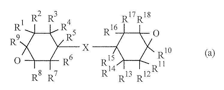
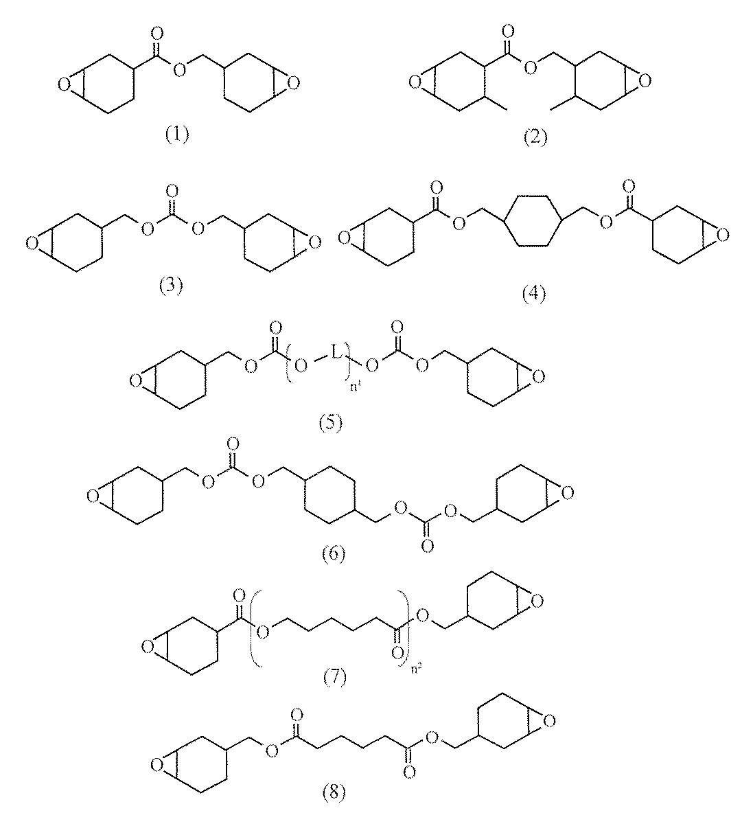
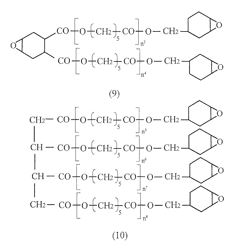
本発明の成分(B)は光の照射によってカチオン種を発生してカチオン硬化性化合物の硬化反応を開始させる光カチオン重合開始剤である。光カチオン重合開始剤は、光を吸収するカチオン部と酸の発生源となるアニオン部からなる。
本発明の封止用組成物は、成分(C)としてグリコールウリル化合物を含有する。グリコールウリル化合物は光カチオン重合開始剤から発生するカチオンに対して弱塩基性を示すため、光照射を施すことにより光カチオン重合開始剤から発生したカチオンをトラップする作用を有し、光照射後は、加熱処理を施すまでは硬化の進行を抑制することができる。すなわち、硬化遅延効果を発揮する。また、光照射後に加熱処理を施すことによりトラップしたカチオンを放出し、封止用組成物の硬化を進行させる働きを有する。そのため、加熱処理を施すタイミングを調整することにより硬化の開始をコントロールすることができ、貼り合わせ作業の遅滞により貼り合わせが困難となる事態が発生することを防止することができる。グリコールウリル化合物は、1種を単独で、又は2種以上を組み合わせて使用することができる。
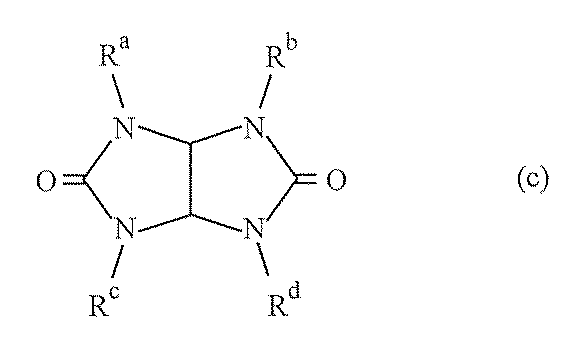
本発明の封止用組成物は、成分(D)として、上記成分(A)以外のカチオン硬化性化合物を1種又は2種以上含んでいてもよい。
本発明の封止用組成物は上記成分以外にも、必要に応じて添加剤を1種又は2種以上含有していても良い。前記添加剤としては、例えば、導電性材料、無機充填材、重合禁止剤、シランカップリング剤、酸化防止剤、光安定剤、可塑剤、レベリング剤、消泡剤、溶剤、紫外線吸収剤、イオン吸着体、顔料、蛍光体、離型剤等を挙げることができる。
導電性繊維被覆粒子とは、粒子状物質と、該粒子状物質を被覆する繊維状の導電性物質(本明細書では「導電性繊維」と称する場合がある)とを含む導電性繊維被覆粒子である。尚、導電性繊維被覆粒子において「導電性繊維が粒子状物質を被覆する」とは、導電性繊維が粒子状物質の表面の一部又は全部を覆った状態を意味する。導電性繊維被覆粒子は、導電性繊維が粒子状物質の表面の少なくとも一部を被覆していればよく、例えば、被覆された部分よりも被覆されていない部分の方が多く存在していてもよい。また、必ずしも粒子状物質と導電性繊維とが接触している必要はないが、通常、導電性繊維の一部は粒子状物質の表面に接触している。
本発明における導電性繊維被覆粒子を構成する粒子状物質は、粒子状の構造体である。
すなわち、本発明の有機EL素子封止用組成物に含まれる導電性繊維被覆粒子は、下記式を満たすことが好ましい。
|粒子状物質の屈折率−有機EL素子封止用組成物(導電性繊維被覆粒子は含まない)の硬化物の屈折率|≦0.1
導電性繊維被覆粒子を構成する導電性繊維は、導電性を有する繊維状の構造体(線状構造体)である。上記導電性繊維の形状は繊維状(ファイバー状)であればよく、特に限定されないが、その平均アスペクト比は例えば10以上、好ましくは20~5000、特に好ましくは50~3000、最も好ましくは100~1000である。平均アスペクト比が上記範囲を下回ると、導電性繊維被覆粒子を少量配合しただけでは優れた導電性を発現させることが困難となる場合がある。上記導電性繊維の平均アスペクト比は、粒子状物質の平均アスペクト比と同様の方法で求められる。尚、上記導電性繊維における「繊維状」の概念には、「ワイヤー状」、「ロッド状」等の各種の線状構造体の形状も含まれる。また、本明細書においては、平均太さが1000nm以下の繊維を「ナノワイヤ」と称する場合がある。
長さ=投影面積/投影径
(1)上記粒子状物質を溶媒に分散させた分散液(「粒子分散液」と称する)と、上記導電性繊維を溶媒に分散させた分散液(「繊維分散液」と称する)とを混合し、必要に応じて溶媒を除去して、本発明における導電性繊維被覆粒子(又は導電性繊維被覆粒子の分散液)を得る。
(2)上記粒子分散液に上記導電性繊維を配合し、混合した後、必要に応じて溶媒を除去して、導電性繊維被覆粒子(又は導電性繊維被覆粒子の分散液)を得る。
(3)上記繊維分散液に上記粒子状物質を配合し、混合した後、必要に応じて溶媒を除去して、導電性繊維被覆粒子(又は導電性繊維被覆粒子の分散液)を得る。
(4)溶媒に上記粒子状物質及び上記導電性繊維を配合し、混合した後、必要に応じて溶媒を除去して、導電性繊維被覆粒子(又は導電性繊維被覆粒子の分散液)を得る。
本発明の有機ELデバイスは、本発明の封止用組成物の硬化物を備えた有機エレクトロルミネッセンスデバイスであり、有機EL素子を本発明の封止用組成物で封止して得られる。
工程1:本発明の有機EL素子封止用組成物からなる塗膜に、光照射を施す
工程2:有機EL素子を設置した基板の素子設置面に、工程1を経て得られた光照射後の塗膜を貼り合わせて加熱処理を施す
<方法1:図2参照>
工程1−1:リッド上に本発明の封止用組成物を塗布して塗膜/リッド積層体を形成する
工程1−2:塗膜に光照射を施す
工程2−1:基板上に有機EL素子を設置し、有機EL素子設置面に光照射後の塗膜/リッド積層体を塗膜面が素子設置面に相対するように貼り合わせる
工程2−2:加熱処理を施すことにより塗膜を硬化させる
工程1−1’:剥離紙等の表面に本発明の封止用組成物を塗布して封止用シート又はフィルムを形成する
工程1−2’:封止用シート又はフィルムに光照射を施す
工程2−1:基板上に有機EL素子を設置し、有機EL素子設置面側に光照射後の封止用シート又はフィルムを介してリッドを貼り合わせる
工程2−2:加熱処理を施すことにより封止用シート又はフィルムを硬化させる
表に記載の処方に従って各成分を自転・公転ミキサー(商品名「あわとり練太郎 ARE−310」、(株)シンキー製)内に投入し、撹拌して封止用組成物(1)を得た。
粘度上昇度=紫外線照射後30分の間の粘度/紫外線照射直後の粘度
その後、紫外線照射後の塗膜(1)を100℃で1時間加熱して硬化物(1)を得た(ポストキュア)。
得られた硬化物(1)について、下記方法によりアウトガス量及び水蒸気透過性を評価した。
表に記載の通りに処方を変更した以外は実施例1と同様にして封止用組成物を得、塗膜を得、硬化物を得た。尚、実施例6ではポストキュアの温度を150℃に変更した。
得られた硬化物について、下記方法によりアウトガス量及び水蒸気透過性を評価した。
実施例及び比較例で得られた硬化物の硬化遅延剤由来のアウトガス量(単位:ppm)は、バイヤル瓶に硬化物60mgを入れ、UV照射(2000mJ/cm2)して100℃の条件下で1時間静置した後、バイヤル瓶中のアウトガス量を測定した。尚、トルエン標準液[標準物質としてトルエン:100ppm、溶媒としてヘキサン:60mg]を用いて検量線を作成した。また、測定機器としては、商品名「HP−6890N」(ヒューレットパッカート社製)を使用し、カラムは商品名「DB−624」(アジレント社製)を使用した。
実施例及び比較例で得られた硬化物の水蒸気透過性は、硬化物(厚み:100μm)の透湿量(g/m2・day・atm)を、JIS L 1099及びJIS Z 0208(カップ法)に準じて、60℃、90%RH条件下で測定して評価した。
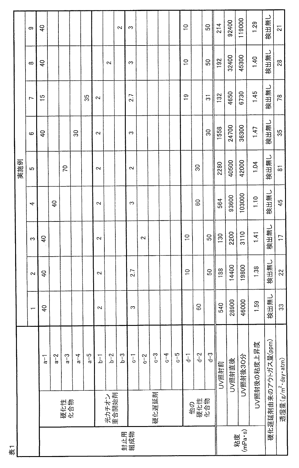
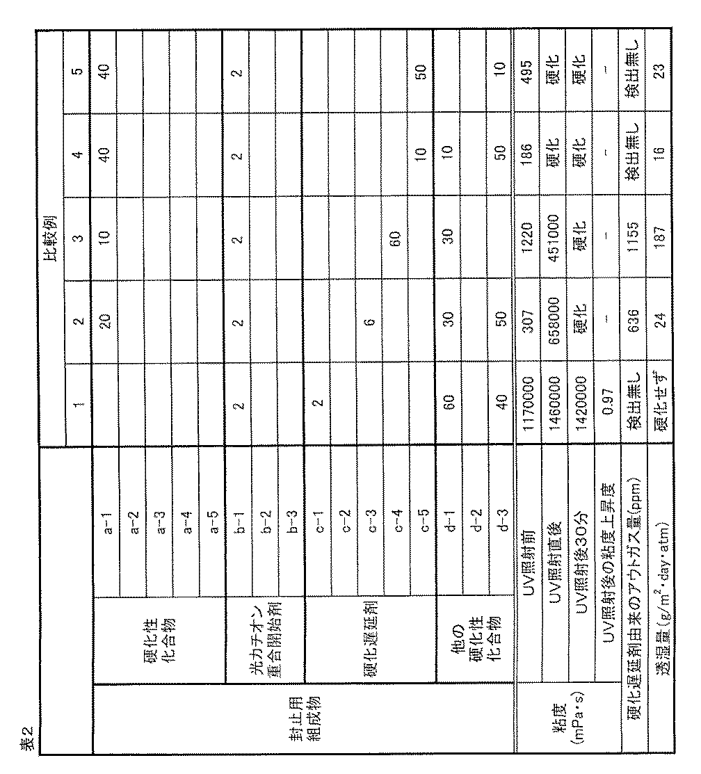
(カチオン硬化性化合物)
a−1:(3,4,3’,4’−ジエポキシ)ビシクロヘキシル
a−2:ビス(3,4−エポキシシクロヘキシルメチル)エーテル
a−3:4,4’−ビス[(3−エチル−3−オキセタニル)メトキシメチル]ビフェニル、商品名「ETERNACOLL OXBP」、宇部興産(株)製
a−4:エピスルフィド末端フルオレン化合物、商品名「CS−500」、大阪ガスケミカル(株)製
a−5:オキシノルボルネンジビニルエーテル、商品名「ONB−DVE」、(株)ダイセル製
(光カチオン重合開始剤)
b−1:4−(4−ビフェニリルチオ)フェニル−4−ビフェニリルフェニルスルホニウム テトラキス(ペンタフルオロフェニル)ボレート
b−2:ジフェニル[4−(フェニルチオ)フェニル]スルホニウム トリス(ペンタフルオロエチル)トリフルオロホスフェート
b−3:4−(4−ビフェニリルチオ)フェニル−4−ビフェニリルフェニルスルホニウム ヘキサフルオロアンチモネート
(硬化遅延剤)
c−1:1,3,4,6−テトラグリシジルグリコールウリル、商品名「TG−G」、四国化成工業(株)製
c−2:1,3,4,6−テトラアリルグリコールウリル、商品名「TA−G」、四国化成工業(株)製
c−3:クラウンエーテル、商品名「18−クラウン−6」、日本曹達(株)製
c−4:ビスフェノールAビス(トリエチレングリコールグリシジルエーテル)エーテル、商品名「リカレジンBEO−60E」、新日本理化(株)製
c−5:1,3,5−トリス(4,5−エポキシペンチル)−1,3,5−トリアジン−2,4,6−トリオン、商品名「TEPIC−VL」、日産化学工業(株)製
(他のカチオン硬化性化合物)
d−1:液状ビスフェノールFジグリシジルエーテル、商品名「YL−983U」、三菱化学(株)製
d−2:ビスフェノールEジグリシジルエーテル、商品名「R1710」、プリンテック(株)製
d−3:o−フェニルフェノールグリシジルエーテル、商品名「SY−OPG」、阪本薬品工業(株)製
そのため、本発明の有機EL素子封止用組成物や本発明の有機EL素子封止用組成物から成るシート又はフィルムは、トップ・エミッション型有機EL素子の封止用途に好適に使用することができる。
2 ダム
3 ディスペンサー
4 封止用組成物
5 基板
6 陰極
7 発光層
8 陽極
Claims (9)
- 下記成分(A)、成分(B)、及び成分(C)を含有する有機エレクトロルミネッセンス素子封止用組成物。
成分(A):脂環エポキシ基、オキセタン環含有基、エピスルフィド基、及びビニルエーテル基から選択される1種又は2種以上の基を1分子中に2個以上有するカチオン硬化性化合物
成分(B):光カチオン重合開始剤
成分(C):グリコールウリル化合物 - 成分(C)がグリシジル基もしくはアリル基を含有するグリコールウリル化合物である請求項1に記載の有機エレクトロルミネッセンス素子封止用組成物。
- 成分(B)1重量部に対して、成分(C)を0.05~3重量部含有する請求項1又は2に記載の有機エレクトロルミネッセンス素子封止用組成物。
- さらに、下記成分(D)を含有する請求項1~3の何れか1項に記載の有機エレクトロルミネッセンス素子封止用組成物。
成分(D):グリシジルエーテル基を1分子中に1個以上有する化合物(成分(A)に含まれる化合物を除く) - さらに、平均粒子径が0.001~30μmの無機充填材を含有する請求項1~4の何れか1項に記載の有機エレクトロルミネッセンス素子封止用組成物。
- さらに、下記導電性繊維被覆粒子を含有する請求項1~5の何れか1項に記載の有機エレクトロルミネッセンス素子封止用組成物。
導電性繊維被覆粒子:粒子状物質と、該粒子状物質を被覆する繊維状の導電性物質とを含む導電性繊維被覆粒子 - トップ・エミッション型有機エレクトロルミネッセンス素子封止用である請求項1~6の何れか1項に記載の有機エレクトロルミネッセンス素子封止用組成物。
- 下記工程1及び2を経て有機エレクトロルミネッセンス素子を封止することを特徴とする有機エレクトロルミネッセンスデバイスの製造方法。
工程1:請求項1~7の何れか1項に記載の有機エレクトロルミネッセンス素子封止用組成物からなる塗膜に、光照射を施す
工程2:有機エレクトロルミネッセンス素子を設置した基板の素子設置面に、工程1を経て得られた光照射後の塗膜を貼り合わせて加熱処理を施す - 請求項1~7の何れか1項に記載の有機エレクトロルミネッセンス素子封止用組成物の硬化物を備えた有機エレクトロルミネッセンスデバイス。
Priority Applications (3)
| Application Number | Priority Date | Filing Date | Title |
|---|---|---|---|
| KR1020187016231A KR102624114B1 (ko) | 2015-11-30 | 2016-11-24 | 밀봉용 조성물 |
| CN201680067352.6A CN108353475A (zh) | 2015-11-30 | 2016-11-24 | 密封用组合物 |
| JP2017554164A JPWO2017094809A1 (ja) | 2015-11-30 | 2016-11-24 | 封止用組成物 |
Applications Claiming Priority (2)
| Application Number | Priority Date | Filing Date | Title |
|---|---|---|---|
| JP2015-233349 | 2015-11-30 | ||
| JP2015233349 | 2015-11-30 |
Publications (1)
| Publication Number | Publication Date |
|---|---|
| WO2017094809A1 true WO2017094809A1 (ja) | 2017-06-08 |
Family
ID=58796964
Family Applications (1)
| Application Number | Title | Priority Date | Filing Date |
|---|---|---|---|
| PCT/JP2016/085653 Ceased WO2017094809A1 (ja) | 2015-11-30 | 2016-11-24 | 封止用組成物 |
Country Status (5)
| Country | Link |
|---|---|
| JP (1) | JPWO2017094809A1 (ja) |
| KR (1) | KR102624114B1 (ja) |
| CN (1) | CN108353475A (ja) |
| TW (1) | TW201738291A (ja) |
| WO (1) | WO2017094809A1 (ja) |
Cited By (4)
| Publication number | Priority date | Publication date | Assignee | Title |
|---|---|---|---|---|
| WO2019021933A1 (ja) * | 2017-07-28 | 2019-01-31 | 株式会社ダイセル | モノマー混合物、及びそれを含む硬化性組成物 |
| WO2019021932A1 (ja) * | 2017-07-28 | 2019-01-31 | 株式会社ダイセル | モノマー混合物、及びそれを含む硬化性組成物 |
| WO2019203123A1 (ja) * | 2018-04-20 | 2019-10-24 | 積水化学工業株式会社 | 有機el表示素子用封止剤及びトップエミッション型有機el表示素子 |
| WO2025047574A1 (ja) * | 2023-08-29 | 2025-03-06 | 株式会社ダイセル | 硬化性エポキシ組成物 |
Families Citing this family (1)
| Publication number | Priority date | Publication date | Assignee | Title |
|---|---|---|---|---|
| TWI691521B (zh) | 2018-12-10 | 2020-04-21 | 新應材股份有限公司 | 可撓性封裝材料、其製備方法及使用所述材料的封裝方法 |
Citations (4)
| Publication number | Priority date | Publication date | Assignee | Title |
|---|---|---|---|---|
| WO2015087714A1 (ja) * | 2013-12-09 | 2015-06-18 | 積水化学工業株式会社 | 表示素子用封止剤 |
| JP2015120889A (ja) * | 2013-11-20 | 2015-07-02 | 四国化成工業株式会社 | エポキシ樹脂組成物および光半導体装置 |
| WO2015111635A1 (ja) * | 2014-01-23 | 2015-07-30 | 電気化学工業株式会社 | 樹脂組成物 |
| WO2015111525A1 (ja) * | 2014-01-23 | 2015-07-30 | 株式会社ダイセル | 封止用組成物 |
Family Cites Families (3)
| Publication number | Priority date | Publication date | Assignee | Title |
|---|---|---|---|---|
| JP4384509B2 (ja) | 2003-01-09 | 2009-12-16 | 積水化学工業株式会社 | 有機エレクトロルミネッセンス素子の封止方法及び有機エレクトロルミネッセンス素子 |
| JP5099851B2 (ja) * | 2009-04-27 | 2012-12-19 | 太陽ホールディングス株式会社 | 光硬化性熱硬化性樹脂組成物、そのドライフィルム及び硬化物並びにそれらを用いたプリント配線板 |
| CN104718579A (zh) * | 2012-07-24 | 2015-06-17 | 株式会社大赛璐 | 被导电性纤维包覆的粒子以及固化性组合物及其固化物 |
-
2016
- 2016-11-24 JP JP2017554164A patent/JPWO2017094809A1/ja active Pending
- 2016-11-24 KR KR1020187016231A patent/KR102624114B1/ko active Active
- 2016-11-24 WO PCT/JP2016/085653 patent/WO2017094809A1/ja not_active Ceased
- 2016-11-24 CN CN201680067352.6A patent/CN108353475A/zh active Pending
- 2016-11-28 TW TW105139070A patent/TW201738291A/zh unknown
Patent Citations (4)
| Publication number | Priority date | Publication date | Assignee | Title |
|---|---|---|---|---|
| JP2015120889A (ja) * | 2013-11-20 | 2015-07-02 | 四国化成工業株式会社 | エポキシ樹脂組成物および光半導体装置 |
| WO2015087714A1 (ja) * | 2013-12-09 | 2015-06-18 | 積水化学工業株式会社 | 表示素子用封止剤 |
| WO2015111635A1 (ja) * | 2014-01-23 | 2015-07-30 | 電気化学工業株式会社 | 樹脂組成物 |
| WO2015111525A1 (ja) * | 2014-01-23 | 2015-07-30 | 株式会社ダイセル | 封止用組成物 |
Cited By (8)
| Publication number | Priority date | Publication date | Assignee | Title |
|---|---|---|---|---|
| WO2019021933A1 (ja) * | 2017-07-28 | 2019-01-31 | 株式会社ダイセル | モノマー混合物、及びそれを含む硬化性組成物 |
| WO2019021932A1 (ja) * | 2017-07-28 | 2019-01-31 | 株式会社ダイセル | モノマー混合物、及びそれを含む硬化性組成物 |
| JP2019026720A (ja) * | 2017-07-28 | 2019-02-21 | 株式会社ダイセル | モノマー混合物、及びそれを含む硬化性組成物 |
| JP2019026721A (ja) * | 2017-07-28 | 2019-02-21 | 株式会社ダイセル | モノマー混合物、及びそれを含む硬化性組成物 |
| TWI701300B (zh) * | 2017-07-28 | 2020-08-11 | 日商大賽璐股份有限公司 | 單體混合物及包含該單體混合物的硬化性組成物 |
| US11028225B2 (en) | 2017-07-28 | 2021-06-08 | Daicel Corporation | Monomer mixture and curable composition containing same |
| WO2019203123A1 (ja) * | 2018-04-20 | 2019-10-24 | 積水化学工業株式会社 | 有機el表示素子用封止剤及びトップエミッション型有機el表示素子 |
| WO2025047574A1 (ja) * | 2023-08-29 | 2025-03-06 | 株式会社ダイセル | 硬化性エポキシ組成物 |
Also Published As
| Publication number | Publication date |
|---|---|
| KR102624114B1 (ko) | 2024-01-12 |
| KR20180088413A (ko) | 2018-08-03 |
| TW201738291A (zh) | 2017-11-01 |
| CN108353475A (zh) | 2018-07-31 |
| JPWO2017094809A1 (ja) | 2018-09-13 |
Similar Documents
| Publication | Publication Date | Title |
|---|---|---|
| JP5914778B2 (ja) | 封止用組成物 | |
| JP5926458B2 (ja) | 光半導体封止用硬化性組成物 | |
| WO2017094809A1 (ja) | 封止用組成物 | |
| WO2017099055A1 (ja) | 封止用組成物 | |
| WO2015033878A1 (ja) | 樹脂組成物及びその硬化物 | |
| JP7523568B2 (ja) | 封止剤、硬化体、有機エレクトロルミネッセンス表示装置、及び、有機エレクトロルミネッセンス表示装置の製造方法 | |
| JP2015137338A (ja) | 導電性繊維被覆粒子を含む硬化性組成物 | |
| JP2015196783A (ja) | シート状組成物 | |
| WO2021201013A1 (ja) | 封止剤、硬化体、有機エレクトロルミネッセンス表示装置、及び、有機エレクトロルミネッセンス表示装置の製造方法 | |
| JP2015137339A (ja) | 導電性繊維被覆粒子を含む硬化性組成物 | |
| JP2015137336A (ja) | 導電性繊維被覆粒子を含む硬化性組成物 | |
| JP2015151528A (ja) | 硬化性組成物 | |
| JP2015137337A (ja) | 導電性繊維被覆粒子を含む硬化性組成物 | |
| KR102955287B1 (ko) | 밀봉제, 경화체, 유기 전계발광 표시장치, 및 유기 전계발광 표시장치의 제조 방법 | |
| TWI913336B (zh) | 密封劑、硬化體、有機電致發光顯示裝置、以及有機電致發光顯示裝置之製造方法 | |
| CN116003958A (zh) | 密封材料组合物以及密封材料 | |
| JP6301643B2 (ja) | 光透過型モジュール | |
| CN114891225A (zh) | 含氟的poss杂化体及其制备方法、光固化组合物和有机封装薄膜 |
Legal Events
| Date | Code | Title | Description |
|---|---|---|---|
| 121 | Ep: the epo has been informed by wipo that ep was designated in this application |
Ref document number: 16870746 Country of ref document: EP Kind code of ref document: A1 |
|
| ENP | Entry into the national phase |
Ref document number: 2017554164 Country of ref document: JP Kind code of ref document: A |
|
| NENP | Non-entry into the national phase |
Ref country code: DE |
|
| ENP | Entry into the national phase |
Ref document number: 20187016231 Country of ref document: KR Kind code of ref document: A |
|
| 122 | Ep: pct application non-entry in european phase |
Ref document number: 16870746 Country of ref document: EP Kind code of ref document: A1 |