WO2017090419A1 - 内燃機関の吸気装置 - Google Patents
内燃機関の吸気装置 Download PDFInfo
- Publication number
- WO2017090419A1 WO2017090419A1 PCT/JP2016/083043 JP2016083043W WO2017090419A1 WO 2017090419 A1 WO2017090419 A1 WO 2017090419A1 JP 2016083043 W JP2016083043 W JP 2016083043W WO 2017090419 A1 WO2017090419 A1 WO 2017090419A1
- Authority
- WO
- WIPO (PCT)
- Prior art keywords
- external gas
- gas introduction
- introduction nozzle
- intake
- egr gas
- Prior art date
- Legal status (The legal status is an assumption and is not a legal conclusion. Google has not performed a legal analysis and makes no representation as to the accuracy of the status listed.)
- Ceased
Links
Images


Classifications
-
- F—MECHANICAL ENGINEERING; LIGHTING; HEATING; WEAPONS; BLASTING
- F02—COMBUSTION ENGINES; HOT-GAS OR COMBUSTION-PRODUCT ENGINE PLANTS
- F02M—SUPPLYING COMBUSTION ENGINES IN GENERAL WITH COMBUSTIBLE MIXTURES OR CONSTITUENTS THEREOF
- F02M26/00—Engine-pertinent apparatus for adding exhaust gases to combustion-air, main fuel or fuel-air mixture, e.g. by exhaust gas recirculation [EGR] systems
- F02M26/13—Arrangement or layout of EGR passages, e.g. in relation to specific engine parts or for incorporation of accessories
- F02M26/17—Arrangement or layout of EGR passages, e.g. in relation to specific engine parts or for incorporation of accessories in relation to the intake system
- F02M26/20—Feeding recirculated exhaust gases directly into the combustion chambers or into the intake runners
-
- F—MECHANICAL ENGINEERING; LIGHTING; HEATING; WEAPONS; BLASTING
- F02—COMBUSTION ENGINES; HOT-GAS OR COMBUSTION-PRODUCT ENGINE PLANTS
- F02M—SUPPLYING COMBUSTION ENGINES IN GENERAL WITH COMBUSTIBLE MIXTURES OR CONSTITUENTS THEREOF
- F02M25/00—Engine-pertinent apparatus for adding non-fuel substances or small quantities of secondary fuel to combustion-air, main fuel or fuel-air mixture
- F02M25/06—Engine-pertinent apparatus for adding non-fuel substances or small quantities of secondary fuel to combustion-air, main fuel or fuel-air mixture adding lubricant vapours
-
- F—MECHANICAL ENGINEERING; LIGHTING; HEATING; WEAPONS; BLASTING
- F02—COMBUSTION ENGINES; HOT-GAS OR COMBUSTION-PRODUCT ENGINE PLANTS
- F02M—SUPPLYING COMBUSTION ENGINES IN GENERAL WITH COMBUSTIBLE MIXTURES OR CONSTITUENTS THEREOF
- F02M26/00—Engine-pertinent apparatus for adding exhaust gases to combustion-air, main fuel or fuel-air mixture, e.g. by exhaust gas recirculation [EGR] systems
- F02M26/13—Arrangement or layout of EGR passages, e.g. in relation to specific engine parts or for incorporation of accessories
- F02M26/17—Arrangement or layout of EGR passages, e.g. in relation to specific engine parts or for incorporation of accessories in relation to the intake system
-
- F—MECHANICAL ENGINEERING; LIGHTING; HEATING; WEAPONS; BLASTING
- F02—COMBUSTION ENGINES; HOT-GAS OR COMBUSTION-PRODUCT ENGINE PLANTS
- F02M—SUPPLYING COMBUSTION ENGINES IN GENERAL WITH COMBUSTIBLE MIXTURES OR CONSTITUENTS THEREOF
- F02M35/00—Combustion-air cleaners, air intakes, intake silencers, or induction systems specially adapted for, or arranged on, internal-combustion engines
- F02M35/10—Air intakes; Induction systems
-
- F—MECHANICAL ENGINEERING; LIGHTING; HEATING; WEAPONS; BLASTING
- F02—COMBUSTION ENGINES; HOT-GAS OR COMBUSTION-PRODUCT ENGINE PLANTS
- F02M—SUPPLYING COMBUSTION ENGINES IN GENERAL WITH COMBUSTIBLE MIXTURES OR CONSTITUENTS THEREOF
- F02M35/00—Combustion-air cleaners, air intakes, intake silencers, or induction systems specially adapted for, or arranged on, internal-combustion engines
- F02M35/10—Air intakes; Induction systems
- F02M35/10006—Air intakes; Induction systems characterised by the position of elements of the air intake system in direction of the air intake flow, i.e. between ambient air inlet and supply to the combustion chamber
- F02M35/10072—Intake runners
-
- F—MECHANICAL ENGINEERING; LIGHTING; HEATING; WEAPONS; BLASTING
- F02—COMBUSTION ENGINES; HOT-GAS OR COMBUSTION-PRODUCT ENGINE PLANTS
- F02M—SUPPLYING COMBUSTION ENGINES IN GENERAL WITH COMBUSTIBLE MIXTURES OR CONSTITUENTS THEREOF
- F02M35/00—Combustion-air cleaners, air intakes, intake silencers, or induction systems specially adapted for, or arranged on, internal-combustion engines
- F02M35/10—Air intakes; Induction systems
- F02M35/10209—Fluid connections to the air intake system; their arrangement of pipes, valves or the like
- F02M35/10222—Exhaust gas recirculation [EGR]; Positive crankcase ventilation [PCV]; Additional air admission, lubricant or fuel vapour admission
-
- F—MECHANICAL ENGINEERING; LIGHTING; HEATING; WEAPONS; BLASTING
- F02—COMBUSTION ENGINES; HOT-GAS OR COMBUSTION-PRODUCT ENGINE PLANTS
- F02M—SUPPLYING COMBUSTION ENGINES IN GENERAL WITH COMBUSTIBLE MIXTURES OR CONSTITUENTS THEREOF
- F02M35/00—Combustion-air cleaners, air intakes, intake silencers, or induction systems specially adapted for, or arranged on, internal-combustion engines
- F02M35/10—Air intakes; Induction systems
- F02M35/10242—Devices or means connected to or integrated into air intakes; Air intakes combined with other engine or vehicle parts
- F02M35/10275—Means to avoid a change in direction of incoming fluid, e.g. all intake ducts diverging from plenum chamber at acute angles; Check valves; Flame arrestors for backfire prevention
-
- F—MECHANICAL ENGINEERING; LIGHTING; HEATING; WEAPONS; BLASTING
- F02—COMBUSTION ENGINES; HOT-GAS OR COMBUSTION-PRODUCT ENGINE PLANTS
- F02M—SUPPLYING COMBUSTION ENGINES IN GENERAL WITH COMBUSTIBLE MIXTURES OR CONSTITUENTS THEREOF
- F02M35/00—Combustion-air cleaners, air intakes, intake silencers, or induction systems specially adapted for, or arranged on, internal-combustion engines
- F02M35/10—Air intakes; Induction systems
- F02M35/10314—Materials for intake systems
- F02M35/10321—Plastics; Composites; Rubbers
-
- F—MECHANICAL ENGINEERING; LIGHTING; HEATING; WEAPONS; BLASTING
- F02—COMBUSTION ENGINES; HOT-GAS OR COMBUSTION-PRODUCT ENGINE PLANTS
- F02M—SUPPLYING COMBUSTION ENGINES IN GENERAL WITH COMBUSTIBLE MIXTURES OR CONSTITUENTS THEREOF
- F02M35/00—Combustion-air cleaners, air intakes, intake silencers, or induction systems specially adapted for, or arranged on, internal-combustion engines
- F02M35/10—Air intakes; Induction systems
- F02M35/1034—Manufacturing and assembling intake systems
- F02M35/10354—Joining multiple sections together
- F02M35/1036—Joining multiple sections together by welding, bonding or the like
-
- F—MECHANICAL ENGINEERING; LIGHTING; HEATING; WEAPONS; BLASTING
- F02—COMBUSTION ENGINES; HOT-GAS OR COMBUSTION-PRODUCT ENGINE PLANTS
- F02M—SUPPLYING COMBUSTION ENGINES IN GENERAL WITH COMBUSTIBLE MIXTURES OR CONSTITUENTS THEREOF
- F02M35/00—Combustion-air cleaners, air intakes, intake silencers, or induction systems specially adapted for, or arranged on, internal-combustion engines
- F02M35/10—Air intakes; Induction systems
- F02M35/104—Intake manifolds
-
- F—MECHANICAL ENGINEERING; LIGHTING; HEATING; WEAPONS; BLASTING
- F02—COMBUSTION ENGINES; HOT-GAS OR COMBUSTION-PRODUCT ENGINE PLANTS
- F02M—SUPPLYING COMBUSTION ENGINES IN GENERAL WITH COMBUSTIBLE MIXTURES OR CONSTITUENTS THEREOF
- F02M35/00—Combustion-air cleaners, air intakes, intake silencers, or induction systems specially adapted for, or arranged on, internal-combustion engines
- F02M35/10—Air intakes; Induction systems
- F02M35/104—Intake manifolds
- F02M35/112—Intake manifolds for engines with cylinders all in one line
-
- Y—GENERAL TAGGING OF NEW TECHNOLOGICAL DEVELOPMENTS; GENERAL TAGGING OF CROSS-SECTIONAL TECHNOLOGIES SPANNING OVER SEVERAL SECTIONS OF THE IPC; TECHNICAL SUBJECTS COVERED BY FORMER USPC CROSS-REFERENCE ART COLLECTIONS [XRACs] AND DIGESTS
- Y02—TECHNOLOGIES OR APPLICATIONS FOR MITIGATION OR ADAPTATION AGAINST CLIMATE CHANGE
- Y02T—CLIMATE CHANGE MITIGATION TECHNOLOGIES RELATED TO TRANSPORTATION
- Y02T10/00—Road transport of goods or passengers
- Y02T10/10—Internal combustion engine [ICE] based vehicles
- Y02T10/12—Improving ICE efficiencies
Definitions
- the present invention relates to an intake device for an internal combustion engine, and more particularly to an intake device for an internal combustion engine in which external gas is introduced into an intake pipe.
- an intake device for an internal combustion engine in which external gas is introduced into the intake pipe is known.
- Such an intake device is disclosed in, for example, Japanese Patent No. 3964690.
- Japanese Patent No. 3964690 discloses a manifold (intake device) of a multi-cylinder (four-cylinder) engine in which blow-by gas (unburned mixture) is introduced into an intake pipe.
- a notch for introducing blow-by gas is provided in the intake pipe of each cylinder.
- a distribution passage groove for distributing blowby gas to each cylinder and the intake pipe of each cylinder are connected via a notch in the intake pipe.
- the length of the notch in the direction in which the blow-by gas flows is larger than the width of the notch (in the direction perpendicular to the direction in which the blow-by gas flows). small. That is, the blow-by gas is introduced into the intake pipe from the distribution passage groove through a relatively short cutout.
- blow-by gas is introduced into the intake pipe from the distribution passage groove through a relatively short path (notch), so that the air flowing in the intake pipe is reduced. Due to the pulsation, there is a disadvantage that air may flow backward from the intake pipe to the distribution channel groove (external gas channel) through the notch. For this reason, there exists a problem that the performance of an engine may fall.
- the present invention has been made to solve the above-described problems, and one object of the present invention is to reduce engine performance due to the backflow of air into the external gas passage. It is an object to provide an intake device for an internal combustion engine that can be suppressed.
- an intake device for an internal combustion engine includes a plurality of intake pipes respectively connected to the cylinders of the internal combustion engine having a plurality of cylinders, and externally connected to the plurality of intake pipes.
- An external gas passage for distributing gas, and the external gas passage is provided so as to extend toward the head port of the head of the internal combustion engine connected to the intake pipe, and introduces the external gas into the intake pipe.
- the length of the external gas introduction nozzle in the direction in which the external gas introduction nozzle extends is greater than the equivalent diameter of the outlet portion of the external gas introduction nozzle.
- the length of the external gas introduction nozzle in the direction in which the external gas introduction nozzle extends is larger than the equivalent diameter of the outlet portion of the external gas introduction nozzle. .
- the inner peripheral surface of the external gas introduction nozzle is preferably formed in a tapered shape that tapers toward the head port.
- the pressure loss when air flows backward from the intake pipe to the external gas introduction nozzle is larger than when the inner diameter of the external gas introduction nozzle is constant. It is possible to further suppress the deterioration of the engine performance due to the reverse flow. Further, by forming the inner peripheral surface of the external gas introduction nozzle in a tapered shape that tapers toward the head port, the external gas is introduced toward the head port, so that the flow of the intake air flowing through the intake pipe is obstructed. Is suppressed. As a result, it is possible to suppress a decrease in the flow rate of the intake air.
- an external gas introduction nozzle can be resin-molded integrally with an air intake apparatus main body, without adding a member (piece) separately.
- the corner portion of the inlet portion where the external gas of the external gas introduction nozzle is introduced preferably has a roundness.
- the external gas introduction nozzle is preferably provided so as to protrude into the intake pipe.
- the external gas introduction nozzle is preferably disposed closer to the head port side of the internal combustion engine than the central portion of the intake path of the intake pipe.
- the external gas introduction nozzle is disposed closer to the head port side of the internal combustion engine than the central portion of the intake path of the intake pipe, so that the gap between the external gas introduction nozzle and the engine cylinder is set. Therefore, the response of introducing external gas to the engine can be improved. As a result, the fuel consumption of the internal combustion engine can be improved.
- the external gas passage further includes an external gas introduction port and an external gas distribution portion, and the external gas The corner of the inlet portion in the vicinity of the boundary between the distributor and the external gas introduction nozzle is rounded.
- the external gas can be smoothly introduced into the external gas passage from the external gas distributor.
- the external gas is an exhaust gas recirculation.
- This configuration makes it possible to reduce pumping loss (intake and exhaust loss), improve fuel efficiency, and further improve emissions.
- the intake device for an internal combustion engine further includes an intake device main body provided with an intake pipe, and the intake device main body is formed by joining a plurality of pieces formed in a divided manner,
- the intake pipe is formed to be curved, and includes a first piece that forms the inner peripheral side of the curved intake pipe, a second piece that forms the outer peripheral side of the curved intake pipe and the inner peripheral side of the external gas passage, A third piece constituting the outer peripheral side of the external gas passage, the external gas passage further including an external gas introduction port and an external gas distribution portion, and the external gas distribution portion is a tournament shape branched hierarchically
- the external gas introduction nozzle is integrally provided in the portion of the second piece corresponding to the lowest layer of the external gas distribution portion formed in the tournament shape.
- the protruding length of the external gas introduction nozzle from the inlet portion into which the external gas is introduced into the intake pipe is larger than the equivalent diameter of the outlet portion of the external gas introduction nozzle.
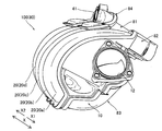
- 1 is a perspective view of an intake device according to a first embodiment of the present invention.
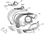
- 1 is an exploded perspective view of an intake device according to a first embodiment of the present invention. It is a front view of the upper piece of the air intake device according to the first embodiment of the present invention. It is sectional drawing of the intake device by 1st Embodiment of this invention. It is a rear view of the upper piece of the air intake device according to the first embodiment of the present invention. It is sectional drawing of the intake device by 2nd Embodiment of this invention.
- the intake device 100 is mounted on an in-line four-cylinder engine 110 (see FIG. 4). As shown in FIGS. 1 and 2, the intake device 100 constitutes a part of an intake system that supplies air to the engine 110.
- the intake device 100 includes a surge tank 10 and a downstream of the surge tank 10.
- An intake device main body 80 is provided.
- the intake air that reaches the intake intake 12 flows into the surge tank 10 via an air cleaner (not shown) as an intake passage and a throttle valve (not shown).
- the engine 110 is configured such that EGR (Exhaust Gas Recirculation) gas, which is part of exhaust gas exhausted to the outside from a combustion chamber (cylinder (not shown)), is recirculated through the intake device 100.
- EGR exhaust Gas Recirculation
- the EGR gas separated from the exhaust gas is cooled to a predetermined temperature (about 100 ° C.) and then introduced into the intake device main body 80. Further, the EGR gas contains moisture.
- the EGR gas is an example of the “external gas” in the claims.
- the intake device main body 80 (surge tank 10, intake pipe 20, and EGR gas introduction nozzle 43, which will be described later) is formed by resin molding (for example, resin molding by polyamide resin). As shown in FIG. 2, the intake device main body 80 is formed by joining a plurality of pieces formed by dividing the intake device main body 80. The plurality of intake pipes 20 are curved.
- the intake device main body 80 includes an upper piece 81 that constitutes an outer peripheral side of the curved intake pipe 20 and an inner peripheral side of an EGR gas passage 40 described later.
- the intake device main body 80 includes a middle piece 82 that constitutes the inner peripheral side of the curved intake pipe 20 and the upper half of the surge tank 10.
- the intake device main body 80 includes a lower piece 83 constituting the lower half of the surge tank 10.
- the intake device main body 80 includes an EGR gas piece 84 that forms the outer peripheral side of the EGR gas passage 40.
- the intake device main body 80 is formed by joining and integrating the upper piece 81, the middle piece 82, the lower piece 83, and the EGR gas piece 84 by vibration welding.
- the EGR gas passage 40 is an example of the “external gas passage” in the claims.
- the middle piece 82, the upper piece 81, and the EGR gas piece 84 are examples of the “first piece”, the “second piece”, and the “third piece” in the claims, respectively.
- the surge tank 10 includes a hollow body 11 formed so as to extend along a cylinder row of the engine 110 (see FIG. 4). Further, a plurality of (four) intake pipes 20 (intake pipes 20a, 20b, 20c and 20d) connected to the cylinders of the engine 110 having a plurality (four) of cylinders are connected to the body 11. ing.
- the engine 110 is configured to introduce EGR gas.
- the intake device main body 80 is provided with EGR gas passages 40 for distributing EGR gas to a plurality of (four) intake pipes 20 (intake pipes 20a to 20d). Yes.
- the inner peripheral side of the EGR gas passage 40 is constituted by an upper piece 81, and the outer peripheral side is constituted by an EGR gas piece 84 (see FIG. 2).
- the EGR gas passage 40 includes an EGR gas inlet 41 and an EGR gas distributor 42. Moreover, the EGR gas distribution part 42 is formed in the tournament shape branched hierarchically. Specifically, the EGR gas distribution unit 42 includes a first level flow path 42a (X1 side) and a flow path 42b (X2 side) branched into two from the EGR gas introduction port 41. The EGR gas distribution unit 42 includes a second-level flow path 42c (X1 side) and a flow path 42d (X2 side) in which the first-level flow path 42a (X1 side) branches into two.
- the EGR gas distribution unit 42 includes a second-level flow path 42e (X1 side) and a flow path 42f (X2 side) in which the first-level flow path 42b (X2 side) branches into two. Note that the length L1 in the X direction of the flow path 42c (flow path 42e) of the second hierarchy is larger than the length L2 in the X direction of the flow path 42d (flow path 42f).
- the EGR gas inlet 41 and the EGR gas distributor 42 are examples of “external gas inlet” and “external gas distributor” in the claims, respectively.
- the EGR gas passage 40 is provided so as to extend toward the head port 100 b of the head 100 a of the engine 110 connected to the intake pipe 20. It has an EGR gas introduction nozzle 43 for introducing EGR gas.
- the length L3 of the EGR gas introduction nozzle 43 in the extending direction of the EGR gas introduction nozzle 43 is larger than the equivalent diameter D1 of the outlet portion 43a of the EGR gas introduction nozzle 43.
- the length L3 is greater than twice the equivalent diameter D1. Note that four EGR gas introduction nozzles 43 (see EGR gas introduction nozzles 431, 432, 433 and 434, FIG. 3 and FIG.
- the configurations of the EGR gas introduction nozzles 431 to 434 are the same as each other.
- the EGR gas introduction nozzle 43 is an example of the “external gas introduction nozzle” in the claims. Hereinafter, the configuration of one EGR gas introduction nozzle 43 will be described.
- the EGR gas introduction nozzle 43 is provided so as to protrude into the intake pipe 20. Further, the EGR gas introduction nozzle 43 is provided so as to protrude toward the head port 100 b of the engine 110.
- the protruding length D3 of the EGR gas introduction nozzle 43 from the inlet portion 43b into which the EGR gas is introduced into the intake pipe 20 is larger than the equivalent diameter D1 of the outlet portion 43a of the EGR gas introduction nozzle 43.
- the length L3 of the EGR gas introduction nozzle 43 from the inlet portion 43b into which the EGR gas is introduced to the outlet portion 43a is larger than the equivalent diameter D1 of the outlet portion 43a.
- the inlet portion 43b includes a portion 43c on the head port 100b side of the engine 110 (the upper surface 43f side of the inner peripheral surface 43e) and a portion 43d on the opposite side of the head port 100b (the lower surface 43g side of the inner peripheral surface 43e).
- the length L3 to the outlet portion 43a is different.
- the length L3 from the portion 43c (the upper surface 43f side of the inner peripheral surface 43e) of the engine 110 on the head port 100b side to the outlet portion 43a is the shortest, opposite to the head port 100b.
- the length from the side portion 43d (the lower surface 43g side of the inner peripheral surface 43e) to the outlet portion 43a is the longest.
- the length L3 to the outlet part 43a is comprised so that it may become larger than the equivalent diameter D1 of the outlet part 43a.
- the outlet portion 43a of the EGR gas introduction nozzle 43 has a substantially perfect circle shape. That is, the equivalent diameter D1 of the outlet portion 43a of the EGR gas introduction nozzle 43 is substantially equal to the diameter r of the substantially circular outlet portion 43a.
- the length L3 of the EGR gas introduction nozzle 43 from the inlet portion 43b into which the EGR gas is introduced to the outlet portion 43a is the equivalent diameter of the outlet portion 21 of the head port 100b of the intake pipe 20 It is configured to be smaller than d and larger than 1 ⁇ 2 of the equivalent diameter d.
- the outlet portion 21 of the head port 100b of the intake pipe 20 is not a perfect circle.
- the inner peripheral surface 43e of the EGR gas introduction nozzle 43 is formed in a tapered shape that tapers toward the head port 100b.
- the upper surface 43f side of the inner peripheral surface 43e of the EGR gas introduction nozzle 43 is configured to extend substantially linearly along the direction toward the head port 100b.
- the lower surface 43g side of the inner peripheral surface 43e of the EGR gas introduction nozzle 43 is configured to extend substantially linearly so as to be inclined with respect to the upper surface 43f. Accordingly, the equivalent diameter D1 (diameter r) of the outlet portion 43a of the EGR gas introduction nozzle 43 is smaller than the equivalent diameter D2 on the inlet portion 43b side.
- the EGR gas introduced from the EGR gas introduction nozzle 43 is the air flowing through the intake pipe 20. It is introduced along the flow direction of (intake).
- the outer peripheral surface 43h of the EGR gas introduction nozzle 43 is formed so as to taper toward the head port 100b. That is, the thickness t (the thickness t on the lower surface 43g side and the side surface 43i side other than the upper surface 43f side) of the EGR gas introduction nozzle 43 extends from the inlet portion 43b side to the outlet portion 43a side of the EGR gas introduction nozzle 43. Almost equal. The thickness t of the EGR gas introduction nozzle 43 is slightly smaller in the vicinity of the outlet portion 43a.
- the corner portion 43j of the inlet portion 43b into which the EGR gas of the EGR gas introduction nozzle 43 is introduced has a roundness. Specifically, as shown in FIG. 3, the corner 43j of the inlet portion 43b in the vicinity of the boundary between the EGR gas distribution portion 42 and the EGR gas introduction nozzle 43 of the EGR gas passage 40 is rounded. That is, the inlet portion 43b of the EGR gas introduction nozzle 43 is cylindrical and has a funnel R shape that warps outward.
- the EGR gas introduction nozzle 43 is arranged on the head port 100 b side (see FIG. 4) of the engine 110 with respect to the central portion of the intake path C ⁇ b> 1 of the intake pipe 20. Yes. Specifically, the intake air flows into the surge tank 10 from the intake intake 12. The intake air is distributed from the surge tank 10 to each intake pipe 20 (intake pipes 20a to 20d). Thereafter, the intake air flows into the engine 110 from the intake pipe 20.
- the EGR gas introduction nozzle 43 is disposed in the vicinity of the head port 100b of the engine 110 in the intake path C1 of the intake pipe 20 (intake air).
- the EGR gas introduction nozzle 43 is provided integrally with a portion of the upper piece 81 corresponding to the lowest layer (second layer) of the EGR gas distribution part 42 formed in a tournament shape. ing. Specifically, of the four EGR gas introduction nozzles 431 to 434, the EGR gas introduction nozzle 431 is provided in the vicinity of the end portion on the X1 side of the flow path 42c of the EGR gas distribution portion 42 constituted by the upper piece 81. Yes.
- the EGR gas introduction nozzle 432 is provided in the vicinity of the end portion on the X2 side of the flow path 42d.
- the EGR gas introduction nozzle 433 is provided in the vicinity of the end portion on the X1 side of the flow path 42e.
- the EGR gas introduction nozzle 434 is provided in the vicinity of the end portion on the X2 side of the flow path 42f.
- a portion 43k (FIG. 3) connecting the flow path 42a (flow path 42b) of the EGR gas distribution section 42 and the flow path 42c (flow path 42d, flow path 42e, flow path 42f).
- Reference) (EGR gas path C2) is inclined downward by a predetermined angle ⁇ (for example, 5 degrees) with respect to the horizontal line h (dashed line).
- the length L3 of the EGR gas introduction nozzle 43 in the direction in which the EGR gas introduction nozzle 43 extends is made larger than the equivalent diameter D1 of the outlet portion 43a of the EGR gas introduction nozzle 43.
- the inner peripheral surface 43e of the EGR gas introduction nozzle 43 is formed in a tapered shape that tapers toward the head port 100b.
- the pressure loss when the air flows back from the intake pipe 20 to the EGR gas introduction nozzle 43 becomes larger, so that the air enters the EGR gas passage 40. It is possible to further suppress the performance of the engine 110 from being deteriorated due to the reverse flow.
- the inner peripheral surface 43e of the EGR gas introduction nozzle 43 in a tapered shape that tapers toward the head port 100b, the EGR gas is introduced toward the head port 100b, and therefore flows in the intake pipe 20.
- the mold is attached to the head port 100b when the EGR gas introduction nozzle 43 is formed by resin molding.
- the EGR gas introduction nozzle 43 can be easily resin-molded by moving it to the opposite side (the direction opposite to the tapering direction). Thereby, the EGR gas introduction nozzle 43 can be resin-molded integrally with the intake device main body 80 without adding a separate member (piece).
- the corner portion 43j of the inlet portion 43b into which the EGR gas of the EGR gas introduction nozzle 43 is introduced is configured to be rounded.
- the pressure loss when the EGR gas is introduced into the EGR gas introduction nozzle 43 is reduced as compared with the case where the corner portion 43j of the inlet portion 43b has a square shape, so that the EGR gas can be smoothly introduced into the intake pipe 20. Can be introduced.
- the EGR gas introduction nozzle 43 is provided so as to protrude into the intake pipe 20. Thereby, unlike the case where the EGR gas introduction nozzle 43 is disposed outside the intake pipe 20 without protruding into the intake pipe 20, it is possible to prevent the intake device 100 from becoming large.
- the EGR gas introduction nozzle 43 is disposed closer to the head port 100b of the engine 110 than the central portion of the intake path C1 of the intake pipe 20.
- the distance between the EGR gas introduction nozzle 43 and the cylinder (cylinder) of the engine 110 is relatively large, on / off timing of a valve for controlling introduction and stop of the EGR gas into the intake pipe 20;
- the difference from the timing at which the EGR gas is introduced into the cylinder of the engine 110 becomes large (responsiveness deteriorates). For this reason, in order to stop the introduction of EGR gas into the cylinders of the engine 110 at a desired timing, it is necessary to advance the timing at which the valve is turned off.
- the EGR gas introduction nozzle 43 is disposed closer to the head port 100b side of the engine 110 than the central portion of the intake path C1 of the intake pipe 20. Since the distance between the engine 110 and the cylinder of the engine 110 is relatively small, the responsiveness of introducing the EGR gas to the engine 110 can be improved. As a result, the fuel consumption of the engine 110 can be improved.
- the corner portion 43j of the inlet portion 43b in the vicinity of the boundary between the EGR gas distribution portion 42 and the EGR gas introduction nozzle 43 is configured to be rounded. Thereby, EGR gas can be smoothly introduced into the EGR gas introduction nozzle 43 from the EGR gas distributor 42.
- EGR gas is introduced into the intake pipe 20 as described above.
- the pumping loss intake and exhaust loss
- the fuel consumption can be improved, and the emission can be further improved.
- the EGR gas introduction nozzle 43 is integrally provided on the upper piece 81 corresponding to the lowest layer of the EGR gas distribution section 42 formed in a tournament shape. Therefore, since it is not necessary to add a member (piece) separately in order to provide the EGR gas introduction nozzle 43, it can suppress that a number of parts increases.
- the protruding length D3 of the EGR gas introduction nozzle 43 from the inlet portion 43b into which the EGR gas is introduced into the intake pipe 20 is set as the outlet portion of the EGR gas introduction nozzle 43. It is larger than the equivalent diameter D1 of 43a.
- the lower surface 43g of the inner peripheral surface 43e of the EGR gas introduction nozzle 43 is configured to extend substantially linearly toward the head port 100b.
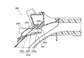
- the lower surface 243d of the inner peripheral surface 243c of the EGR gas introduction nozzle 243 is configured to be bent.
- the lower surface 243d of the inner peripheral surface 243c is the first lower surface portion 243e provided on the inlet portion 243b side of the EGR gas introduction nozzle 243.
- a second lower surface portion 243f provided in the vicinity of the center portion and a third lower surface portion 243g provided on the outlet portion 243a side.
- the first lower surface portion 243e and the second lower surface portion 243f are provided to be inclined with respect to the upper surface 243h.
- the third lower surface portion 243g is provided substantially in parallel with the upper surface 243h.
- the lower surface 243d has a shape bent by the first lower surface portion 243e, the second lower surface portion 243f, and the third lower surface portion 243g.
- the inner diameter of the portion corresponding to the third lower surface portion 243g does not substantially change toward the head port 100b (has a cylindrical shape).
- a portion of the inner peripheral surface 243c of the EGR gas introduction nozzle 243 corresponding to the second lower surface portion 243f is formed in a tapered shape that tapers toward the head port 100b.
- the intake device 100 (intake device 200) mounted on the in-line four-cylinder engine 110
- the present invention is not limited to this.
- the intake device of the present invention may be mounted on an in-line multi-cylinder engine other than the in-line 4-cylinder engine, or may be mounted on a V-type multi-cylinder engine or a horizontally opposed engine.
- a gasoline engine, a diesel engine, a gas engine, or the like can be applied.
- this invention installs not only in the engine (internal combustion engine) mounted in a general vehicle (automobile) but in transportation equipment, such as a train and a ship, and also stationary equipment other than transportation equipment.
- the present invention can also be applied to an intake device mounted on an internal combustion engine or the like.
- the outlet portion 43a of the EGR gas introduction nozzle 43 (the outlet portion 243a of the EGR gas introduction nozzle 243) has a substantially circular shape
- the outlet portion of the EGR gas introduction nozzle may have a shape (such as an elliptical shape) other than a substantially perfect circle shape.
- the inner peripheral surface 43e of the EGR gas introduction nozzle 43 (the inner peripheral surface 243c of the EGR gas introduction nozzle 243) is formed in a tapered shape that tapers toward the head port 100b.
- the present invention is not limited to this.
- the inner peripheral surface of the EGR gas introduction nozzle may not be tapered toward the head port (the inner diameter may be constant toward the head port).
- the EGR gas introduction nozzle 43 (EGR gas introduction nozzle 243) is provided so as to protrude into the intake pipe 20
- the EGR gas introduction nozzle may be arranged outside the intake pipe so that the EGR gas introduction nozzle does not protrude into the intake pipe.
- EGR gas exhaust gas recirculation gas
- PCV gas blow-by gas
- the intake device main body 80 is formed of resin (polyamide resin) has been shown, but the present invention is not limited to this.
- the intake device body may be made of metal.
- the intake pipe 20 is not provided with a valve that changes the length of the intake pipe 20 (the length of the intake path) is shown.
- the present invention is not limited to this. I can't.
- the present invention may be applied to an intake pipe provided with a valve that changes the length of the intake pipe (length of the intake path).
- EGR gas passage (external gas passage) 41 EGR gas inlet (external gas inlet) 42 EGR gas distributor (external gas distributor) 43, 243 EGR gas introduction nozzle (external gas introduction nozzle) 43a, 243a Outlet portion 43b, 243b Inlet portion 43e, 243c Inner peripheral surface 43j Corner portion 80 Intake device main body 81 Upper piece (second piece) 82 Middle piece (first piece) 84 EGR gas piece (third piece) 100 Intake device 110 Engine (internal combustion engine) 110a head 110b head port C1 intake path D1 equivalent diameter L3 (external gas introduction nozzle) length
Landscapes
- Engineering & Computer Science (AREA)
- Chemical & Material Sciences (AREA)
- Combustion & Propulsion (AREA)
- Mechanical Engineering (AREA)
- General Engineering & Computer Science (AREA)
- Manufacturing & Machinery (AREA)
- Exhaust-Gas Circulating Devices (AREA)
Abstract
この内燃機関の吸気装置では、外部ガス通路は、吸気管に外部ガスを導入する外部ガス導入ノズルを有し、外部ガス導入ノズルの外部ガス導入ノズルが延びる方向の長さは、外部ガス導入ノズルの出口部分の相当直径よりも大きい。
Description
本発明は、内燃機関の吸気装置に関し、特に、吸気管に外部ガスが導入される内燃機関の吸気装置に関する。
従来、吸気管に外部ガスが導入される内燃機関の吸気装置が知られている。このような吸気装置は、たとえば、特許第3964690号公報に開示されている。
特許第3964690号公報には、ブローバイガス(未燃焼の混合気)が吸気管に導入される多気筒(4気筒)エンジンのマニホルド(吸気装置)が開示されている。この特許第3964690号公報に記載の吸気装置では、各気筒の吸気管にブローバイガスを導入するための切欠部が設けられている。そして、吸気管の切欠部を介して、ブローバイガスを各気筒に分配する分配通路用溝部と、各気筒の吸気管とが接続されている。また、切欠部のブローバイガスの流れる方向の長さ(分配通路用溝部と吸気管との間の長さ)は、切欠部の幅(ブローバイガスの流れる方向に直交する方向の幅)に比べて小さい。すなわち、ブローバイガスは、比較的短い経路の切欠部を介して分配通路用溝部から吸気管に導入されている。
しかしながら、特許第3964690号公報に記載された吸気装置では、ブローバイガスが、比較的短い経路(切欠部)を介して分配通路用溝部から吸気管に導入されているため、吸気管内を流れる空気の脈動に起因して、空気が吸気管から切欠部を介して分配通路用溝部(外部ガス通路)に逆流する場合があるという不都合がある。このため、エンジンの性能が低下する場合があるという問題点がある。
この発明は、上記のような課題を解決するためになされたものであり、この発明の1つの目的は、空気が外部ガス通路に逆流することに起因して、エンジンの性能が低下するのを抑制することが可能な内燃機関の吸気装置を提供することである。
上記目的を達成するために、この発明の一の局面における内燃機関の吸気装置は、複数の気筒数を有する内燃機関の気筒にそれぞれ接続される複数の吸気管と、複数の吸気管にそれぞれ外部ガスを分配する外部ガス通路と、を備え、外部ガス通路は、吸気管に接続される内燃機関のヘッドのヘッドポートに向かって延びるように設けられ、吸気管に外部ガスを導入する外部ガス導入ノズルを有し、外部ガス導入ノズルの外部ガス導入ノズルが延びる方向の長さは、外部ガス導入ノズルの出口部分の相当直径よりも大きい。
この発明の一の局面による内燃機関の吸気装置では、上記のように、外部ガス導入ノズルの外部ガス導入ノズルが延びる方向の長さを、外部ガス導入ノズルの出口部分の相当直径よりも大きくする。これにより、外部ガス導入ノズルの長さが比較的大きくなるので、空気が吸気管から外部ガス導入ノズルに逆流する場合の圧力損失が大きくなる。その結果、空気が吸気管から外部ガス導入ノズルに逆流しにくくなるので、空気が外部ガス通路に逆流することに起因して、エンジンの性能が低下するのを抑制することができる。また、空気が吸気管から外部ガス導入ノズルに逆流しにくくなるので、外部ガスの複数の気筒に対する分配量に偏りが生じるのを抑制する(分配性を向上させる)ことができる。
上記一の局面による内燃機関の吸気装置において、好ましくは、外部ガス導入ノズルの内周面は、ヘッドポートに向かって先細るテーパ形状に形成されている。
このように構成すれば、外部ガス導入ノズルの内径が一定である場合と比べて、空気が吸気管から外部ガス導入ノズルに逆流する場合の圧力損失がより大きくなるので、空気が外部ガス通路に逆流することに起因して、エンジンの性能が低下するのをより抑制することができる。また、外部ガス導入ノズルの内周面を、ヘッドポートに向かって先細るテーパ形状に形成することによって、ヘッドポートに向かって外部ガスが導入されるので、吸気管内を流れる吸気の流れを阻害するのが抑制される。その結果、吸気の流速が低下するのを抑制することができる。また、外部ガス導入ノズルの内周面を、ヘッドポートに向かって先細るテーパ形状に形成することによって、外部ガス導入ノズルを樹脂成形により形成する際に、金型をヘッドポートとは反対側(先細る方向とは反対方向)に移動させることにより、容易に、外部ガス導入ノズルを樹脂成形することができる。これにより、別途部材(ピース)を追加することなく、吸気装置本体と一体的に外部ガス導入ノズルを樹脂成形することができる。
上記一の局面による内燃機関の吸気装置において、好ましくは、外部ガス導入ノズルの外部ガスが導入される入口部分の角部は、丸みを有する。
このように構成すれば、入口部分の角部が角形状を有する場合と比べて、外部ガス導入ノズルに外部ガスが導入される際の圧力損失が小さくなるので、外部ガスを吸気管にスムーズに導入することができる。
上記一の局面による内燃機関の吸気装置において、好ましくは、外部ガス導入ノズルは、吸気管内に突出するように設けられている。
このように構成すれば、外部ガス導入ノズルが吸気管内に突出せずに吸気管の外部に配置される場合と異なり、吸気装置が大型化するのを抑制することができる。
上記一の局面による内燃機関の吸気装置において、好ましくは、外部ガス導入ノズルは、吸気管の吸気経路の中央部よりも内燃機関のヘッドポート側に配置されている。
ここで、外部ガス導入ノズルとエンジンの気筒(シリンダ)との間の距離が比較的大きい場合、外部ガスの吸気管への導入および停止を制御するためのバルブのオンオフのタイミングと、実際に外部ガスがエンジンの気筒に導入されるタイミングとの差が大きくなる(応答性が悪くなる)。このため、所望のタイミングでエンジンの気筒への外部ガスの導入を停止させるために、バルブをオフするタイミングを早める必要がある。この場合、外部ガスの導入量が低減するので、外部ガスの導入による効果が低減(燃費が低下)する。そこで、本発明では、上記のように、外部ガス導入ノズルを、吸気管の吸気経路の中央部よりも内燃機関のヘッドポート側に配置することにより、外部ガス導入ノズルとエンジンの気筒との間の距離が比較的小さくなるので、エンジンに対する外部ガスの導入の応答性を向上させることができる。その結果、内燃機関の燃費を向上させることができる。
上記外部ガス導入ノズルの外部ガスが導入される入口部分の角部が丸みを有する内燃機関の吸気装置において、外部ガス通路は、外部ガス導入口と、外部ガス分配部とをさらに含み、外部ガス分配部と外部ガス導入ノズルとの境界近傍の入口部分の角部が、丸みを有する。
このように構成すれば、外部ガスを外部ガス分配部から外部ガス通路にスムーズに導入することができる。
上記一の局面による内燃機関の吸気装置において、外部ガスは、排気再循環ガスである。
このように構成すれば、ポンピングロス(吸排気損失)の低減とともに燃費を向上させ、さらにエミッションを向上させることができる。
上記一の局面による内燃機関の吸気装置において、吸気管が設けられる吸気装置本体をさらに備え、吸気装置本体は、分割して形成された複数のピースを接合することにより形成されるとともに、複数の吸気管は、湾曲して形成されており、湾曲する吸気管の内周側を構成する第1ピースと、湾曲する吸気管の外周側および外部ガス通路の内周側を構成する第2ピースと、外部ガス通路の外周側を構成する第3ピースとを含み、外部ガス通路は、外部ガス導入口と、外部ガス分配部とをさらに含み、外部ガス分配部は、階層的に分岐するトーナメント形状に形成されており、外部ガス導入ノズルは、トーナメント形状に形成された外部ガス分配部の最下層の階層に対応する第2ピースの部分に一体的に設けられている。
このように構成すれば、外部ガス導入ノズルを設けるために別途部材(ピース)を追加する必要がないので、部品点数が増加するのを抑制することができる。
上記一の局面による内燃機関の吸気装置において、外部ガス導入ノズルの、外部ガスが導入される入口部分から吸気管内への突出長さは、外部ガス導入ノズルの出口部分の相当直径よりも大きい。
このように構成すれば、空気が吸気管から外部ガス導入ノズルに逆流する場合の圧力損失を十分に大きくすることができるので、空気が吸気管から外部ガス導入ノズルに逆流するのを効果的に抑制することができる。
以下、本発明の実施形態を図面に基づいて説明する。
[第1実施形態]
図1~図5を参照して、本発明の第1実施形態によるエンジン110の吸気装置100の構成について説明する。なお、エンジン110は、特許請求の範囲の「内燃機関」の一例である。
図1~図5を参照して、本発明の第1実施形態によるエンジン110の吸気装置100の構成について説明する。なお、エンジン110は、特許請求の範囲の「内燃機関」の一例である。
本発明の第1実施形態による吸気装置100は、直列4気筒のエンジン110(図4参照)に搭載されている。また、図1および図2に示すように、吸気装置100は、エンジン110に空気を供給する吸気系の一部を構成しており、吸気装置100は、サージタンク10と、サージタンク10の下流に配置される吸気管20とからなる吸気装置本体80を備えている。
また、吸気装置100では、吸気路としてのエアクリーナ(図示せず)およびスロットルバルブ(図示せず)を介して吸気取入口12に到達する吸入空気がサージタンク10に流入される。
また、エンジン110は、燃焼室(シリンダ(図示せず))から外部に排気された排気ガスの一部であるEGR(Exhaust Gas Recirculation)ガスが吸気装置100を介して再循環されるように構成されている。ここで、排気ガスから分離されたEGRガスは、所定温度(約100℃)まで冷却された後、吸気装置本体80に導入される。また、EGRガスには、水分が含まれている。なお、EGRガスは、特許請求の範囲の「外部ガス」の一例である。
吸気装置本体80(サージタンク10、吸気管20、および、後述するEGRガス導入ノズル43など)は、樹脂成形(たとえば、ポリアミド樹脂による樹脂成形)により形成されている。また、図2に示すように、吸気装置本体80は、吸気装置本体80は、分割して形成された複数のピースを接合することにより形成されている。また、複数の吸気管20は、湾曲して形成されている。そして、吸気装置本体80は、湾曲する吸気管20の外周側および後述するEGRガス通路40の内周側を構成するアッパピース81を含む。また、吸気装置本体80は、湾曲する吸気管20の内周側およびサージタンク10の上側半分を構成するミドルピース82を含む。また、吸気装置本体80は、サージタンク10の下側半分を構成するロアピース83を含む。また、吸気装置本体80は、EGRガス通路40の外周側を構成するEGRガスピース84を含む。そして、吸気装置本体80は、アッパピース81、ミドルピース82、ロアピース83、および、EGRガスピース84が振動溶着により互いに接合されて一体化されることにより形成されている。なお、EGRガス通路40は、特許請求の範囲の「外部ガス通路」の一例である。また、ミドルピース82、アッパピース81、および、EGRガスピース84は、それぞれ、特許請求の範囲の「第1ピース」、「第2ピース」、および、「第3ピース」の一例である。
また、図2に示すように、サージタンク10は、エンジン110(図4参照)の気筒(シリンダ)列に沿って延びるように形成された中空構造の胴部11を含んでいる。また、胴部11には、複数(4つ)の気筒数を有するエンジン110の気筒にそれぞれ接続される複数(4つ)の吸気管20(吸気管20a、20b、20cおよび20d)が接続されている。
また、エンジン110には、EGRガスが導入されるように構成されている。具体的には、図3に示すように、吸気装置本体80には、複数(4つ)の吸気管20(吸気管20a~20d)にそれぞれEGRガスを分配するEGRガス通路40が設けられている。EGRガス通路40の内周側は、アッパピース81により構成されているとともに、外周側は、EGRガスピース84(図2参照)により構成されている。
そして、EGRガス通路40は、EGRガス導入口41と、EGRガス分配部42とを含んでいる。また、EGRガス分配部42は、階層的に分岐するトーナメント形状に形成されている。具体的には、EGRガス分配部42は、EGRガス導入口41から2本に分岐した第1階層の流路42a(X1側)および流路42b(X2側)を有する。また、EGRガス分配部42は、第1階層の流路42a(X1側)が2本に分岐した第2階層の流路42c(X1側)および流路42d(X2側)を有する。また、EGRガス分配部42は、第1階層の流路42b(X2側)が2本に分岐した第2階層の流路42e(X1側)および流路42f(X2側)を有する。なお、第2階層の流路42c(流路42e)のX方向の長さL1は、流路42d(流路42f)のX方向の長さL2よりも大きい。なお、EGRガス導入口41およびEGRガス分配部42は、それぞれ、特許請求の範囲の「外部ガス導入口」および「外部ガス分配部」の一例である。
ここで、第1実施形態では、図4に示すように、EGRガス通路40は、吸気管20に接続されるエンジン110のヘッド100aのヘッドポート100bに向かって延びるように設けられ、吸気管20にEGRガスを導入するEGRガス導入ノズル43を有している。そして、EGRガス導入ノズル43のEGRガス導入ノズル43が延びる方向の長さL3は、EGRガス導入ノズル43の出口部分43aの相当直径D1よりも大きい。たとえば、長さL3は、相当直径D1の2倍よりも大きい。なお、EGRガス導入ノズル43は、4つの吸気管20(吸気管20a~20d)に対応するように、4つ(EGRガス導入ノズル431、432、433および434、図3および図5参照)設けられている。EGRガス導入ノズル431~434の構成は互いに同様である。なお、EGRガス導入ノズル43は、特許請求の範囲の「外部ガス導入ノズル」の一例である。以下では、1つのEGRガス導入ノズル43の構成について説明する。
ここで、第1実施形態では、図4に示すように、EGRガス導入ノズル43は、吸気管20内に突出するように設けられている。また、EGRガス導入ノズル43は、エンジン110のヘッドポート100bに向かって突出するように設けられている。そして、EGRガス導入ノズル43の、EGRガスが導入される入口部分43bから吸気管20内への突出長さD3は、EGRガス導入ノズル43の出口部分43aの相当直径D1よりも大きい。詳細には、EGRガス導入ノズル43の、EGRガスが導入される入口部分43bから出口部分43aまでの長さL3が出口部分43aの相当直径D1よりも大きい。なお、入口部分43bは、エンジン110のヘッドポート100b側の部分43c(内周面43eの上面43f側)と、ヘッドポート100bとは反対側の部分43d(内周面43eの下面43g側)とで、出口部分43aまでの長さL3が異なる。ここで、入口部分43bのうち、エンジン110のヘッドポート100b側の部分43c(内周面43eの上面43f側)から、出口部分43aまでの長さL3までが最短となり、ヘッドポート100bとは反対側の部分43d(内周面43eの下面43g側)から、出口部分43aまでの長さL3までが最長となる。そして、第1実施形態では、入口部分43bのいずれの部分においても、出口部分43aまでの長さL3が、出口部分43aの相当直径D1よりも大きくなるように構成されている。
また、図5に示すように、EGRガス導入ノズル43の出口部分43aは、略真円形状を有する。すなわち、EGRガス導入ノズル43の出口部分43aの相当直径D1は、略真円形状の出口部分43aの直径rに略等しい。
また、図4に示すように、EGRガス導入ノズル43の、EGRガスが導入される入口部分43bから出口部分43aまでの長さL3は、吸気管20のヘッドポート100bの出口部分21の相当直径dよりも小さく、相当直径dの1/2よりも大きくなるように構成されている。ここで、吸気管20のヘッドポート100bの出口部分21は、真円ではない。この場合、出口部分21の相当直径dは、吸気管20の流路断面積をAとして、Aを4倍した値を、流路断面にある壁面の長さLで除した値(d=4×A/L)となる。
また、第1実施形態では、図4に示すように、EGRガス導入ノズル43の内周面43eは、ヘッドポート100bに向かって先細るテーパ形状に形成されている。具体的には、EGRガス導入ノズル43の内周面43eの上面43f側は、ヘッドポート100bに向かう方向に沿って略直線状に延びるように構成されている。また、EGRガス導入ノズル43の内周面43eの下面43g側は、上面43fに対して傾斜するように、略直線状に延びるように構成されている。これにより、EGRガス導入ノズル43の出口部分43aの相当直径D1(直径r)は、入口部分43b側の相当直径D2よりも小さくなる。また、EGRガス導入ノズル43の内周面43eは、ヘッドポート100bに向かって先細るテーパ形状に形成されているので、EGRガス導入ノズル43から導入されるEGRガスは、吸気管20を流れる空気(吸気)の流れる方向に沿って導入される。
また、EGRガス導入ノズル43の外周面43hは、ヘッドポート100bに向かって先細るように形成されている。すなわち、EGRガス導入ノズル43の直径方向の厚みt(上面43f側以外の下面43g側、側面43i側の厚みt)は、EGRガス導入ノズル43の入口部分43b側から出口部分43a側に渡って略等しい。なお、EGRガス導入ノズル43の厚みtは、出口部分43a近傍において少し小さくなっている。
また、第1実施形態では、EGRガス導入ノズル43のEGRガスが導入される入口部分43bの角部43jは、丸みを有する。具体的には、図3に示すように、EGRガス通路40のEGRガス分配部42とEGRガス導入ノズル43との境界近傍の入口部分43bの角部43jが、丸みを有する。すなわち、EGRガス導入ノズル43の入口部分43bは、筒状で、外側に反り返るファンネルR形状を有する。
また、第1実施形態では、図3に示すように、EGRガス導入ノズル43は、吸気管20の吸気経路C1の中央部よりもエンジン110のヘッドポート100b側(図4参照)に配置されている。具体的には、吸入空気は、吸気取入口12からサージタンク10に流入する。そして、吸入空気は、サージタンク10から各吸気管20(吸気管20a~20d)に分配される。その後、吸入空気は、吸気管20からエンジン110に流入する。そして、EGRガス導入ノズル43は、吸気管20(吸入空気)の吸気経路C1のうちのエンジン110のヘッドポート100b近傍に配置されている。
また、図3に示すように、EGRガス導入ノズル43は、トーナメント形状に形成されたEGRガス分配部42の最下層の階層(第2階層)に対応するアッパピース81の部分に一体的に設けられている。具体的には、4つのEGRガス導入ノズル431~434のうち、EGRガス導入ノズル431は、アッパピース81により構成されるEGRガス分配部42の流路42cのX1側の端部近傍に設けられている。また、EGRガス導入ノズル432は、流路42dのX2側の端部近傍に設けられている。また、EGRガス導入ノズル433は、流路42eのX1側の端部近傍に設けられている。また、EGRガス導入ノズル434は、流路42fのX2側の端部近傍に設けられている。
また、図4に示すように、EGRガス分配部42の流路42a(流路42b)と、流路42c(流路42d、流路42e、流路42f)とを接続する部分43k(図3参照)(EGRガスの経路C2)は、水平線h(一点鎖線)に対して所定の角度θ(たとえば、5度)下方に傾斜している。これにより、EGRガスに含まれる水分がエンジン110の気筒側に流れるので、EGRガスに含まれる水分がサージタンク10に流れるのを抑制することが可能になる。
(第1実施形態の効果)
第1実施形態では、以下のような効果を得ることができる。
第1実施形態では、以下のような効果を得ることができる。
第1実施形態では、上記のように、EGRガス導入ノズル43のEGRガス導入ノズル43が延びる方向の長さL3を、EGRガス導入ノズル43の出口部分43aの相当直径D1よりも大きくする。これにより、EGRガス導入ノズル43の長さL3が比較的大きくなるので、空気が吸気管20からEGRガス導入ノズル43に逆流する場合の圧力損失が大きくなる。その結果、空気が吸気管20からEGRガス導入ノズル43に逆流しにくくなるので、空気がEGRガス通路40に逆流することに起因して、エンジン110の性能が低下するのを抑制することができる。また、空気が吸気管20からEGRガス導入ノズル43に逆流しにくくなるので、EGRガスの複数の気筒に対する分配量に偏りが生じるのを抑制する(分配性を向上させる)ことができる。
また、第1実施形態では、上記のように、EGRガス導入ノズル43の内周面43eを、ヘッドポート100bに向かって先細るテーパ形状に形成する。これにより、EGRガス導入ノズル43の内径が一定である場合と比べて、空気が吸気管20からEGRガス導入ノズル43に逆流する場合の圧力損失がより大きくなるので、空気がEGRガス通路40に逆流することに起因して、エンジン110の性能が低下するのをより抑制することができる。また、EGRガス導入ノズル43の内周面43eを、ヘッドポート100bに向かって先細るテーパ形状に形成することによって、ヘッドポート100bに向かってEGRガスが導入されるので、吸気管20内を流れる吸気の流れを阻害するのが抑制される。その結果、吸気の流速が低下するのを抑制することができる。また、EGRガス導入ノズル43の内周面43eを、ヘッドポート100bに向かって先細るテーパ形状に形成することによって、EGRガス導入ノズル43を樹脂成形により形成する際に、金型をヘッドポート100bとは反対側(先細る方向とは反対方向)に移動させることにより、容易に、EGRガス導入ノズル43を樹脂成形することができる。これにより、別途部材(ピース)を追加することなく、吸気装置本体80と一体的にEGRガス導入ノズル43を樹脂成形することができる。
また、第1実施形態では、上記のように、EGRガス導入ノズル43のEGRガスが導入される入口部分43bの角部43jを、丸みを有するように構成する。これにより、入口部分43bの角部43jが角形状を有する場合と比べて、EGRガス導入ノズル43にEGRガスが導入される際の圧力損失が小さくなるので、EGRガスを吸気管20にスムーズに導入することができる。
また、第1実施形態では、上記のように、EGRガス導入ノズル43を、吸気管20内に突出するように設ける。これにより、EGRガス導入ノズル43が吸気管20内に突出せずに吸気管20の外部に配置される場合と異なり、吸気装置100が大型化するのを抑制することができる。
また、第1実施形態では、上記のように、EGRガス導入ノズル43を、吸気管20の吸気経路C1の中央部よりもエンジン110のヘッドポート100b側に配置する。ここで、EGRガス導入ノズル43とエンジン110の気筒(シリンダ)との間の距離が比較的大きい場合、EGRガスの吸気管20への導入および停止を制御するためのバルブのオンオフのタイミングと、実際にEGRガスがエンジン110の気筒に導入されるタイミングとの差が大きくなる(応答性が悪くなる)。このため、所望のタイミングでエンジン110の気筒へのEGRガスの導入を停止させるために、バルブをオフするタイミングを早める必要がある。この場合、EGRガスの導入量が低減するので、EGRガスの導入による効果が低減(燃費が低下)する。そこで、上記のように、第1実施形態では、EGRガス導入ノズル43を、吸気管20の吸気経路C1の中央部よりもエンジン110のヘッドポート100b側に配置することにより、EGRガス導入ノズル43とエンジン110の気筒との間の距離が比較的小さくなるので、エンジン110に対するEGRガスの導入の応答性を向上させることができる。その結果、エンジン110の燃費を向上させることができる。
また、第1実施形態では、上記のように、EGRガス分配部42とEGRガス導入ノズル43との境界近傍の入口部分43bの角部43jを、丸みを有するように構成する。これにより、EGRガスをEGRガス分配部42からEGRガス導入ノズル43にスムーズに導入することができる。
また、第1実施形態では、上記のように、EGRガスを吸気管20に導入する。これにより、ポンピングロス(吸排気損失)の低減とともに燃費を向上させ、さらにエミッションを向上させることができる。
また、第1実施形態では、上記のように、EGRガス導入ノズル43を、トーナメント形状に形成されたEGRガス分配部42の最下層の階層に対応するアッパピース81の部分に一体的に設ける。これにより、EGRガス導入ノズル43を設けるために別途部材(ピース)を追加する必要がないので、部品点数が増加するのを抑制することができる。
また、第1実施形態では、上記のように、EGRガス導入ノズル43の、EGRガスが導入される入口部分43bから吸気管20内への突出長さD3を、EGRガス導入ノズル43の出口部分43aの相当直径D1よりも大きくする。これにより、空気が吸気管20からEGRガス導入ノズル43に逆流する場合の圧力損失を十分に大きくすることができるので、空気が吸気管20からEGRガス導入ノズル43に逆流するのを効果的に抑制することができる。
[第2実施形態]
図6を参照して、本発明の第2実施形態によるエンジン110の吸気装置200の構成について説明する。本発明の第2実施形態によるエンジン110の吸気装置200では、EGRガス導入ノズル43の内周面43eの下面43gが、ヘッドポート100bに向かって略直線状に延びるように構成されていた上記第1実施形態とは異なり、EGRガス導入ノズル243の内周面243cの下面243dが、屈曲するように構成されている。
図6を参照して、本発明の第2実施形態によるエンジン110の吸気装置200の構成について説明する。本発明の第2実施形態によるエンジン110の吸気装置200では、EGRガス導入ノズル43の内周面43eの下面43gが、ヘッドポート100bに向かって略直線状に延びるように構成されていた上記第1実施形態とは異なり、EGRガス導入ノズル243の内周面243cの下面243dが、屈曲するように構成されている。
図6に示すように、エンジン110の吸気装置200のEGRガス導入ノズル243では、内周面243cの下面243dは、EGRガス導入ノズル243の入口部分243b側に設けられている第1下面部分243eと、中央部近傍に設けられる第2下面部分243fと、出口部分243a側に設けられている第3下面部分243gとを含む。第1下面部分243e、および、第2下面部分243fは、上面243hに対して傾斜するように設けられている。一方、第3下面部分243gは、上面243hに対して略並行に設けられている。すなわち、下面243dは、第1下面部分243eと、第2下面部分243fと、第3下面部分243gとによって屈曲した形状を有する。そして、EGRガス導入ノズル243の内周面243cのうち、第3下面部分243gに対応する部分は、ヘッドポート100bに向かって内径が略変化しない(円筒形状を有する)。一方、EGRガス導入ノズル243の内周面243cのうち、第2下面部分243fに対応する部分は、ヘッドポート100bに向かって先細るテーパ形状に形成されている。
なお、第2実施形態のその他の構成および効果は、上記第1実施形態と同様である。
なお、今回開示された実施形態は、すべての点で例示であって制限的なものではないと考えられるべきである。本発明の範囲は、上記した実施形態の説明ではなく特許請求の範囲によって示され、さらに特許請求の範囲と均等の意味および範囲内でのすべての変更(変形例)が含まれる。
たとえば、上記第1および第2実施形態では、直列4気筒のエンジン110に搭載される吸気装置100(吸気装置200)に本発明を適用した例について示したが、本発明はこれに限られない。すなわち、本発明の吸気装置を直列4気筒エンジン以外の直列多気筒エンジンに搭載してもよいし、V型多気筒エンジンや水平対向型エンジンなどに搭載してもよい。また、エンジンとしては、ガソリンエンジン、ディーゼルエンジンおよびガスエンジンなどが適用可能である。また、本発明では、一般的な車両(自動車)に搭載されるエンジン(内燃機関)のみならず、列車や船舶などの輸送機器、さらには、輸送機器以外の定置型の設備機器に設置される内燃機関などに搭載される吸気装置に対しても適用可能である。
また、上記第1および第2実施形態では、EGRガス導入ノズル43の出口部分43a(EGRガス導入ノズル243の出口部分243a)が略真円形状を有する例を示したが、本発明はこれに限られない。たとえば、EGRガス導入ノズルの出口部分が略真円形状以外の形状(楕円形状など)を有していてもよい。
また、上記第1および第2実施形態では、EGRガス導入ノズル43の内周面43e(EGRガス導入ノズル243の内周面243c)が、ヘッドポート100bに向かって先細るテーパ形状に形成されている例について示したが、本発明はこれに限られない。たとえば、EGRガス導入ノズルの内周面が、ヘッドポートに向かって先細らなくても(内径がヘッドポートに向かって一定でも)よい。
また、上記第1および第2実施形態では、EGRガス導入ノズル43(EGRガス導入ノズル243)が、吸気管20内に突出するように設けられている例について示したが、本発明はこれに限られない。たとえば、EGRガス導入ノズルが吸気管内に突出しないように、EGRガス導入ノズルを吸気管の外部に配置していてもよい。
また、上記第1および第2実施形態では、EGRガス(排気再循環ガス)を吸気管20に導入した例について示したが、本発明はこれに限られない。たとえば、本発明の「外部ガス」として、クランク室内の換気を目的としたブローバイガス(PCVガス)を吸気管に導入してもよい。
また、上記第1および第2実施形態では、吸気装置本体80を共に樹脂(ポリアミド樹脂)により形成する例について示したが、本発明はこれに限られない。たとえば、吸気装置本体を金属により形成してもよい。
また、上記第1および第2実施形態では、吸気管20に、吸気管20の長さ(吸気経路の長さ)を変えるバルブが設けられていない例について示したが、本発明はこれに限られない。たとえば、吸気管の長さ(吸気経路の長さ)を変えるバルブが設けられている吸気管に、本発明を適用してもよい。
20、20a~20d 吸気管
40 EGRガス通路(外部ガス通路)
41 EGRガス導入口(外部ガス導入口)
42 EGRガス分配部(外部ガス分配部)
43、243 EGRガス導入ノズル(外部ガス導入ノズル)
43a、243a 出口部分
43b、243b 入口部分
43e、243c 内周面
43j 角部
80 吸気装置本体
81 アッパピース(第2ピース)
82 ミドルピース(第1ピース)
84 EGRガスピース(第3ピース)
100 吸気装置
110 エンジン(内燃機関)
110a ヘッド
110b ヘッドポート
C1 吸気経路
D1 相当直径
L3 (外部ガス導入ノズルの)長さ
40 EGRガス通路(外部ガス通路)
41 EGRガス導入口(外部ガス導入口)
42 EGRガス分配部(外部ガス分配部)
43、243 EGRガス導入ノズル(外部ガス導入ノズル)
43a、243a 出口部分
43b、243b 入口部分
43e、243c 内周面
43j 角部
80 吸気装置本体
81 アッパピース(第2ピース)
82 ミドルピース(第1ピース)
84 EGRガスピース(第3ピース)
100 吸気装置
110 エンジン(内燃機関)
110a ヘッド
110b ヘッドポート
C1 吸気経路
D1 相当直径
L3 (外部ガス導入ノズルの)長さ
Claims (9)
- 複数の気筒数を有する内燃機関の前記気筒にそれぞれ接続される複数の吸気管と、
前記複数の吸気管にそれぞれ外部ガスを分配する外部ガス通路と、を備え、
前記外部ガス通路は、前記吸気管に接続される前記内燃機関のヘッドのヘッドポートに向かって延びるように設けられ、前記吸気管に前記外部ガスを導入する外部ガス導入ノズルを有し、
前記外部ガス導入ノズルの前記外部ガス導入ノズルが延びる方向の長さは、前記外部ガス導入ノズルの出口部分の相当直径よりも大きい、内燃機関の吸気装置。 - 前記外部ガス導入ノズルの内周面は、前記ヘッドポートに向かって先細るテーパ形状に形成されている、請求項1に記載の内燃機関の吸気装置。
- 前記外部ガス導入ノズルの前記外部ガスが導入される入口部分の角部は、丸みを有する、請求項1または2に記載の内燃機関の吸気装置。
- 前記外部ガス通路は、外部ガス導入口と、外部ガス分配部とをさらに含み、前記外部ガス分配部と前記外部ガス導入ノズルとの境界近傍の前記入口部分の前記角部が、丸みを有する、請求項3に記載の内燃機関の吸気装置。
- 前記外部ガス導入ノズルは、前記吸気管内に突出するように設けられている、請求項1~4のいずれか1項に記載の内燃機関の吸気装置。
- 前記外部ガス導入ノズルは、前記吸気管の吸気経路の中央部よりも前記内燃機関の前記ヘッドポート側に配置されている、請求項1~5のいずれか1項に記載の内燃機関の吸気装置。
- 前記外部ガスは、排気再循環ガスである、請求項1~6のいずれか1項に記載の内燃機関の吸気装置。
- 前記吸気管が設けられる吸気装置本体をさらに備え、
前記吸気装置本体は、分割して形成された複数のピースを接合することにより形成されるとともに、複数の前記吸気管は、湾曲して形成されており、湾曲する前記吸気管の内周側を構成する第1ピースと、湾曲する前記吸気管の外周側および前記外部ガス通路の内周側を構成する第2ピースと、前記外部ガス通路の外周側を構成する第3ピースとを含み、
前記外部ガス通路は、外部ガス導入口と、外部ガス分配部とをさらに含み、
前記外部ガス分配部は、階層的に分岐するトーナメント形状に形成されており、
前記外部ガス導入ノズルは、トーナメント形状に形成された前記外部ガス分配部の最下層の階層に対応する前記第2ピースの部分に一体的に設けられている、請求項1~7のいずれか1項に記載の内燃機関の吸気装置。 - 前記外部ガス導入ノズルの、前記外部ガスが導入される入口部分から前記吸気管内への突出長さは、前記外部ガス導入ノズルの前記出口部分の相当直径よりも大きい、請求項1~8のいずれか1項に記載の内燃機関の吸気装置。
Priority Applications (3)
| Application Number | Priority Date | Filing Date | Title |
|---|---|---|---|
| CN201690001457.7U CN208831116U (zh) | 2015-11-25 | 2016-11-08 | 内燃机的进气装置 |
| DE112016005387.8T DE112016005387T5 (de) | 2015-11-25 | 2016-11-08 | Luftansaugvorrichtung für Brennkraftmaschine |
| US15/778,043 US10731607B2 (en) | 2015-11-25 | 2016-11-08 | Air intake apparatus for internal combustion engine |
Applications Claiming Priority (2)
| Application Number | Priority Date | Filing Date | Title |
|---|---|---|---|
| JP2015229258A JP6599738B2 (ja) | 2015-11-25 | 2015-11-25 | 内燃機関の吸気装置 |
| JP2015-229258 | 2015-11-25 |
Publications (1)
| Publication Number | Publication Date |
|---|---|
| WO2017090419A1 true WO2017090419A1 (ja) | 2017-06-01 |
Family
ID=58763157
Family Applications (1)
| Application Number | Title | Priority Date | Filing Date |
|---|---|---|---|
| PCT/JP2016/083043 Ceased WO2017090419A1 (ja) | 2015-11-25 | 2016-11-08 | 内燃機関の吸気装置 |
Country Status (5)
| Country | Link |
|---|---|
| US (1) | US10731607B2 (ja) |
| JP (1) | JP6599738B2 (ja) |
| CN (1) | CN208831116U (ja) |
| DE (1) | DE112016005387T5 (ja) |
| WO (1) | WO2017090419A1 (ja) |
Cited By (1)
| Publication number | Priority date | Publication date | Assignee | Title |
|---|---|---|---|---|
| AT520741A4 (de) * | 2018-03-08 | 2019-07-15 | Avl List Gmbh | Brennkraftmaschine |
Families Citing this family (8)
| Publication number | Priority date | Publication date | Assignee | Title |
|---|---|---|---|---|
| JP6599738B2 (ja) * | 2015-11-25 | 2019-10-30 | アイシン精機株式会社 | 内燃機関の吸気装置 |
| JP7200548B2 (ja) * | 2018-08-29 | 2023-01-10 | 株式会社アイシン | インテークマニホールド |
| JP7163251B2 (ja) * | 2019-07-11 | 2022-10-31 | 愛三工業株式会社 | Egrガス分配器 |
| JP7358824B2 (ja) * | 2019-08-01 | 2023-10-11 | マツダ株式会社 | エンジンの吸気装置 |
| JP7297659B2 (ja) * | 2019-12-26 | 2023-06-26 | 愛三工業株式会社 | Egrガス分配器 |
| JP7540252B2 (ja) * | 2020-09-08 | 2024-08-27 | トヨタ紡織株式会社 | インテークマニホールド |
| JP7480732B2 (ja) * | 2021-03-22 | 2024-05-10 | トヨタ紡織株式会社 | Egr装置 |
| CN114858426B (zh) * | 2022-03-23 | 2025-08-29 | 中国联合重型燃气轮机技术有限公司 | 一种用于燃气轮机燃烧室喷嘴测试装置 |
Citations (4)
| Publication number | Priority date | Publication date | Assignee | Title |
|---|---|---|---|---|
| JPS51147822U (ja) * | 1975-05-21 | 1976-11-27 | ||
| JP2011225140A (ja) * | 2010-04-21 | 2011-11-10 | National Maritime Research Institute | 流場制御装置及び流場制御方法 |
| JP2012079601A (ja) * | 2010-10-05 | 2012-04-19 | Japan Ae Power Systems Corp | ガス遮断器 |
| JP2015148188A (ja) * | 2014-02-06 | 2015-08-20 | 愛三工業株式会社 | 吸気装置 |
Family Cites Families (30)
| Publication number | Priority date | Publication date | Assignee | Title |
|---|---|---|---|---|
| EP1015750B1 (de) * | 1997-09-16 | 2003-05-02 | FILTERWERK MANN + HUMMEL GmbH | Anordnung zur rückführung von abgas bei einem verbrennungsmotor |
| JP3964690B2 (ja) | 2002-02-13 | 2007-08-22 | 株式会社マーレ フィルターシステムズ | 内燃機関の合成樹脂製マニホルド |
| US7100559B2 (en) * | 2003-02-19 | 2006-09-05 | Nissan Motor Co., Ltd. | Engine air intake manifold |
| JP2004335990A (ja) * | 2003-03-10 | 2004-11-25 | Fuji Electric Device Technology Co Ltd | Mis型半導体装置 |
| JP3786098B2 (ja) | 2003-03-10 | 2006-06-14 | 日産自動車株式会社 | エンジンの吸気装置 |
| US7067877B2 (en) * | 2003-03-10 | 2006-06-27 | Fuji Electric Device Technology Co., Ltd. | MIS-type semiconductor device |
| JP4452201B2 (ja) * | 2005-02-28 | 2010-04-21 | 愛三工業株式会社 | 吸気マニホールド |
| JP4483965B2 (ja) * | 2008-03-27 | 2010-06-16 | 株式会社デンソー | インテークマニホールド |
| JP4840676B2 (ja) * | 2008-12-17 | 2011-12-21 | アイシン精機株式会社 | 吸気マニホルド |
| US8511289B2 (en) * | 2009-05-18 | 2013-08-20 | Aisan Kogyo Kabushiki Kaisha | Intake manifolds |
| FR2958337B1 (fr) * | 2010-03-31 | 2013-03-01 | Valeo Systemes Thermiques | Collecteur de repartition de gaz dans la culasse d'un moteur, ensemble d'un collecteur de repartition et d'une culasse de moteur. |
| FR2958336B1 (fr) * | 2010-03-31 | 2013-03-15 | Valeo Systemes Thermiques | Collecteur de repartition de gaz dans la culasse d'un moteur avec melange des gaz d'echappement recircules a contre-courant des gaz d'admission. |
| JP5316574B2 (ja) * | 2011-04-04 | 2013-10-16 | 株式会社デンソー | 吸気マニホールド |
| JP2013108381A (ja) * | 2011-11-18 | 2013-06-06 | Honda Motor Co Ltd | 吸気マニホールド |
| JP5891813B2 (ja) * | 2012-01-25 | 2016-03-23 | アイシン精機株式会社 | Pcv通路の凍結防止構造およびインテークマニホールド |
| US20140102429A1 (en) * | 2012-10-12 | 2014-04-17 | GM Global Technology Operations LLC | Inlet manifold with dual port egr |
| CN203476553U (zh) * | 2013-09-25 | 2014-03-12 | 江铃汽车股份有限公司 | 一种进气歧管结构 |
| JP2015169093A (ja) * | 2014-03-05 | 2015-09-28 | 株式会社デンソー | 内燃機関の吸気装置 |
| JP2015224561A (ja) * | 2014-05-26 | 2015-12-14 | トヨタ自動車株式会社 | 排気再循環装置 |
| JP2016079896A (ja) * | 2014-10-17 | 2016-05-16 | アイシン精機株式会社 | 吸気装置 |
| JP6358046B2 (ja) * | 2014-11-04 | 2018-07-18 | アイシン精機株式会社 | 内燃機関の吸気装置および内燃機関の外部ガス分配構造 |
| JP6295929B2 (ja) * | 2014-11-25 | 2018-03-20 | アイシン精機株式会社 | 内燃機関の吸気装置 |
| JP6435976B2 (ja) * | 2015-04-20 | 2018-12-12 | アイシン精機株式会社 | 内燃機関の吸気装置 |
| JP6599738B2 (ja) * | 2015-11-25 | 2019-10-30 | アイシン精機株式会社 | 内燃機関の吸気装置 |
| JP6649758B2 (ja) * | 2015-11-30 | 2020-02-19 | アイシン精機株式会社 | 吸気装置 |
| JP6656006B2 (ja) * | 2016-02-08 | 2020-03-04 | 愛三工業株式会社 | ガス分配装置 |
| KR101826564B1 (ko) * | 2016-03-16 | 2018-02-07 | 현대자동차 주식회사 | 통합된 열교환기를 갖는 엔진 |
| JP6612185B2 (ja) * | 2016-06-14 | 2019-11-27 | 愛三工業株式会社 | 吸気マニホールド |
| JP2018025123A (ja) * | 2016-08-09 | 2018-02-15 | アイシン精機株式会社 | 吸気装置 |
| US10161366B2 (en) * | 2016-11-30 | 2018-12-25 | Aisin Seiki Kabushiki Kaisha | Air intake apparatus |
-
2015
- 2015-11-25 JP JP2015229258A patent/JP6599738B2/ja active Active
-
2016
- 2016-11-08 CN CN201690001457.7U patent/CN208831116U/zh active Active
- 2016-11-08 WO PCT/JP2016/083043 patent/WO2017090419A1/ja not_active Ceased
- 2016-11-08 US US15/778,043 patent/US10731607B2/en active Active
- 2016-11-08 DE DE112016005387.8T patent/DE112016005387T5/de active Pending
Patent Citations (4)
| Publication number | Priority date | Publication date | Assignee | Title |
|---|---|---|---|---|
| JPS51147822U (ja) * | 1975-05-21 | 1976-11-27 | ||
| JP2011225140A (ja) * | 2010-04-21 | 2011-11-10 | National Maritime Research Institute | 流場制御装置及び流場制御方法 |
| JP2012079601A (ja) * | 2010-10-05 | 2012-04-19 | Japan Ae Power Systems Corp | ガス遮断器 |
| JP2015148188A (ja) * | 2014-02-06 | 2015-08-20 | 愛三工業株式会社 | 吸気装置 |
Cited By (2)
| Publication number | Priority date | Publication date | Assignee | Title |
|---|---|---|---|---|
| AT520741A4 (de) * | 2018-03-08 | 2019-07-15 | Avl List Gmbh | Brennkraftmaschine |
| AT520741B1 (de) * | 2018-03-08 | 2019-07-15 | Avl List Gmbh | Brennkraftmaschine |
Also Published As
| Publication number | Publication date |
|---|---|
| US20180347520A1 (en) | 2018-12-06 |
| DE112016005387T5 (de) | 2018-08-09 |
| JP6599738B2 (ja) | 2019-10-30 |
| US10731607B2 (en) | 2020-08-04 |
| JP2017096176A (ja) | 2017-06-01 |
| CN208831116U (zh) | 2019-05-07 |
Similar Documents
| Publication | Publication Date | Title |
|---|---|---|
| JP6599738B2 (ja) | 内燃機関の吸気装置 | |
| US10359007B2 (en) | Intake apparatus for internal combustion engine and outside gas distribution structure for internal combustion engine | |
| US10082112B2 (en) | Gas distribution apparatus | |
| US20140014056A1 (en) | Intake manifold | |
| EP3290682B1 (en) | Intake device for internal combustion engines | |
| US20160201620A1 (en) | Intake system for internal combustion engine | |
| US10527009B2 (en) | Exhaust gas recirculating apparatus | |
| JP6332192B2 (ja) | エンジンの吸気装置 | |
| JP4853481B2 (ja) | 内燃機関の吸気装置 | |
| WO2013002020A1 (ja) | 内燃機関用吸気装置 | |
| JP2013011185A5 (ja) | ||
| US20070012282A1 (en) | Air intake apparatus | |
| JP7188293B2 (ja) | Egrガス分配装置 | |
| JP5187070B2 (ja) | エンジンのインテークマニホールド | |
| JP5006559B2 (ja) | 多気筒内燃機関のegr装置 | |
| BR112015015193B1 (pt) | Arranjo para recirculação de escapamentos em um motor de combustão interna | |
| JP7384104B2 (ja) | 吸気装置 | |
| WO2013047173A1 (ja) | 吸気装置 | |
| JP7176491B2 (ja) | インテークマニホールド | |
| US20210199075A1 (en) | Egr gas distributor | |
| CN110863932B (zh) | 进气歧管 | |
| JP7540252B2 (ja) | インテークマニホールド | |
| JP6166130B2 (ja) | 内燃機関用吸気マニホールド | |
| KR20060006480A (ko) | 에어 인테이크 시스템 | |
| JP2014005804A (ja) | 内燃機関の吸気装置 |
Legal Events
| Date | Code | Title | Description |
|---|---|---|---|
| 121 | Ep: the epo has been informed by wipo that ep was designated in this application |
Ref document number: 16868368 Country of ref document: EP Kind code of ref document: A1 |
|
| WWE | Wipo information: entry into national phase |
Ref document number: 112016005387 Country of ref document: DE |
|
| 122 | Ep: pct application non-entry in european phase |
Ref document number: 16868368 Country of ref document: EP Kind code of ref document: A1 |