WO2017090308A1 - 燃料噴射弁 - Google Patents
燃料噴射弁 Download PDFInfo
- Publication number
- WO2017090308A1 WO2017090308A1 PCT/JP2016/077839 JP2016077839W WO2017090308A1 WO 2017090308 A1 WO2017090308 A1 WO 2017090308A1 JP 2016077839 W JP2016077839 W JP 2016077839W WO 2017090308 A1 WO2017090308 A1 WO 2017090308A1
- Authority
- WO
- WIPO (PCT)
- Prior art keywords
- nozzle
- group
- nozzle holes
- fuel
- hole
- Prior art date
- Legal status (The legal status is an assumption and is not a legal conclusion. Google has not performed a legal analysis and makes no representation as to the accuracy of the status listed.)
- Ceased
Links
Images




Classifications
-
- F—MECHANICAL ENGINEERING; LIGHTING; HEATING; WEAPONS; BLASTING
- F02—COMBUSTION ENGINES; HOT-GAS OR COMBUSTION-PRODUCT ENGINE PLANTS
- F02M—SUPPLYING COMBUSTION ENGINES IN GENERAL WITH COMBUSTIBLE MIXTURES OR CONSTITUENTS THEREOF
- F02M61/00—Fuel-injectors not provided for in groups F02M39/00 - F02M57/00 or F02M67/00
- F02M61/16—Details not provided for in, or of interest apart from, the apparatus of groups F02M61/02 - F02M61/14
- F02M61/18—Injection nozzles, e.g. having valve seats; Details of valve member seated ends, not otherwise provided for
- F02M61/1806—Injection nozzles, e.g. having valve seats; Details of valve member seated ends, not otherwise provided for characterised by the arrangement of discharge orifices, e.g. orientation or size
- F02M61/1813—Discharge orifices having different orientations with respect to valve member direction of movement, e.g. orientations being such that fuel jets emerging from discharge orifices collide with each other
-
- F—MECHANICAL ENGINEERING; LIGHTING; HEATING; WEAPONS; BLASTING
- F02—COMBUSTION ENGINES; HOT-GAS OR COMBUSTION-PRODUCT ENGINE PLANTS
- F02M—SUPPLYING COMBUSTION ENGINES IN GENERAL WITH COMBUSTIBLE MIXTURES OR CONSTITUENTS THEREOF
- F02M61/00—Fuel-injectors not provided for in groups F02M39/00 - F02M57/00 or F02M67/00
- F02M61/16—Details not provided for in, or of interest apart from, the apparatus of groups F02M61/02 - F02M61/14
- F02M61/18—Injection nozzles, e.g. having valve seats; Details of valve member seated ends, not otherwise provided for
- F02M61/1806—Injection nozzles, e.g. having valve seats; Details of valve member seated ends, not otherwise provided for characterised by the arrangement of discharge orifices, e.g. orientation or size
- F02M61/182—Discharge orifices being situated in different transversal planes with respect to valve member direction of movement
-
- F—MECHANICAL ENGINEERING; LIGHTING; HEATING; WEAPONS; BLASTING
- F02—COMBUSTION ENGINES; HOT-GAS OR COMBUSTION-PRODUCT ENGINE PLANTS
- F02M—SUPPLYING COMBUSTION ENGINES IN GENERAL WITH COMBUSTIBLE MIXTURES OR CONSTITUENTS THEREOF
- F02M61/00—Fuel-injectors not provided for in groups F02M39/00 - F02M57/00 or F02M67/00
- F02M61/16—Details not provided for in, or of interest apart from, the apparatus of groups F02M61/02 - F02M61/14
- F02M61/18—Injection nozzles, e.g. having valve seats; Details of valve member seated ends, not otherwise provided for
- F02M61/1806—Injection nozzles, e.g. having valve seats; Details of valve member seated ends, not otherwise provided for characterised by the arrangement of discharge orifices, e.g. orientation or size
- F02M61/1833—Discharge orifices having changing cross sections, e.g. being divergent
-
- F—MECHANICAL ENGINEERING; LIGHTING; HEATING; WEAPONS; BLASTING
- F02—COMBUSTION ENGINES; HOT-GAS OR COMBUSTION-PRODUCT ENGINE PLANTS
- F02M—SUPPLYING COMBUSTION ENGINES IN GENERAL WITH COMBUSTIBLE MIXTURES OR CONSTITUENTS THEREOF
- F02M61/00—Fuel-injectors not provided for in groups F02M39/00 - F02M57/00 or F02M67/00
- F02M61/16—Details not provided for in, or of interest apart from, the apparatus of groups F02M61/02 - F02M61/14
- F02M61/18—Injection nozzles, e.g. having valve seats; Details of valve member seated ends, not otherwise provided for
- F02M61/1853—Orifice plates
-
- F—MECHANICAL ENGINEERING; LIGHTING; HEATING; WEAPONS; BLASTING
- F02—COMBUSTION ENGINES; HOT-GAS OR COMBUSTION-PRODUCT ENGINE PLANTS
- F02M—SUPPLYING COMBUSTION ENGINES IN GENERAL WITH COMBUSTIBLE MIXTURES OR CONSTITUENTS THEREOF
- F02M61/00—Fuel-injectors not provided for in groups F02M39/00 - F02M57/00 or F02M67/00
- F02M61/16—Details not provided for in, or of interest apart from, the apparatus of groups F02M61/02 - F02M61/14
- F02M61/18—Injection nozzles, e.g. having valve seats; Details of valve member seated ends, not otherwise provided for
- F02M61/1886—Details of valve seats not covered by groups F02M61/1866 - F02M61/188
Definitions
- the present invention relates to a fuel injection valve used in an internal combustion engine such as a gasoline engine, in which fuel is prevented from leaking when the valve body comes into contact with the valve seat, and injection is performed when the valve body is separated from the valve seat. It relates to an injection valve.
- Patent Document 1 describes a fuel injection valve that can form two sprays with good penetration properties.
- a plurality of fuel injection holes are divided into a first and a second set of fuel injection holes with a plane including the axis of the valve hole as a boundary, and the first and second sets.
- all the fuel injection holes of the first and second sets are formed to have the same diameter
- the second center line of the fuel nozzle hole located outside is inclined toward the front of the injector plate so as to approach the first center line of the fuel nozzle hole located at or near the center of each set (see summary). .
- the plurality of injection holes are divided into two injection hole groups (first and second sets of fuel injection hole groups), and each of the injection hole groups has both outer sides.
- the other nozzle holes extend in the direction away from the plane extending in the Y direction (boundary direction of the two nozzle hole groups) through the axis of the valve hole of the valve seat member in the injection direction in parallel with the extension line of the central axis It is arranged to incline.
- the angle between the fuel flow direction toward the inlet of the nozzle hole and the inclination direction of the nozzle hole becomes small. For this reason, the collision force (pressing force) of the fuel against the inner wall surface of the nozzle hole is reduced, and there is a problem in atomization of the spray.
- An object of the present invention is to provide a fuel injection valve capable of increasing the collision force of fuel to the inner wall surface of the nozzle hole and realizing sufficient atomization.
- one of the representative fuel injection valves of the present invention is: A valve body configured to be displaceable in a central axis direction; a valve seat that opens and closes a fuel passage in cooperation with the valve body; and a fuel that is provided downstream of the valve seat and that has passed through the fuel passage
- the fuel injected from the plurality of nozzle holes of the first nozzle hole group constituted by a plurality of nozzle holes at least part of the plurality of nozzle holes as a whole
- a fuel injection valve that forms a first fuel spray directed in a first injection direction, Projecting the plurality of nozzle holes constituting the first nozzle hole group and the first injection direction directed by the first fuel spray onto a virtual plane orthogonal to the central axis direction,
- a virtual orthogonal coordinate system having a virtual X axis along one injection direction and a virtual Y axis orthogonal to the virtual X axis, the origin of which coincides with a projection center point obtained by projecting the central axis onto the virtual
- the plurality of nozzle holes constituting the first nozzle hole group has an injection hole central axis from the inlet surface to the outlet surface of the nozzle hole, and the origin and the inlet surface of the virtual orthogonal coordinate system.
- the center of the outlet surface is formed at a position close to the virtual X axis with respect to the center of the inlet surface.
- a fuel injection valve capable of increasing the collision force of fuel to the inner wall surface of the nozzle hole and promoting atomization.
- FIG. 4 is a diagram schematically showing the relationship between the inclination angle of the nozzle hole and the spray interference distance in the BB cross section of FIG. 3. It is the figure which looked at the nozzle plate of the fuel injection valve which concerns on 2nd Example of this invention from the valve body side. It is sectional drawing to which the vicinity of the front-end
- the vertical direction is defined based on FIG. This vertical direction has nothing to do with the vertical direction when the fuel injection valve 1 is mounted on the engine.
- the fuel supply port 2a side (upper end side) of the fuel injection valve 1 is referred to as a base end side
- the nozzle plate 6 side is referred to as a distal end side. This is based on the fact that the fuel supply port 2a side is connected to a fuel pipe (not shown) and receives fuel.
- FIG. 1 is a cross-sectional view of a fuel injection valve 1 according to a first embodiment of the present invention.
- a fuel injection valve 1 supplies fuel to an internal combustion engine used as, for example, an automobile engine.
- the casing 2 is formed in a cylindrical shape having an elongated and thin-walled portion by pressing or cutting.
- the casing 2 has a stepped portion 2b at an intermediate portion between both ends, and is formed in a cylindrical shape that forms an integral structure from substantially the base end portion to the tip end portion of the fuel injection valve 1.
- the material is a ferritic stainless steel material plus a flexible material such as titanium, and has magnetic properties.
- the casing 2 is provided with a fuel supply port 2a at one end surface (upper end surface) and a nozzle plate 6 having a plurality of fuel injection holes (injection holes) at the other end surface (lower end surface).
- the nozzle plate 6 is fixed to the nozzle body 5.
- the nozzle plate 6 has a hole 7 (hereinafter referred to as an injection hole) for injecting fuel (see FIG. 3).
- an electromagnetic coil 14 and a magnetic material yoke 16 surrounding the electromagnetic coil 14 are provided on the outside of the casing 2 in FIG. 1.
- a fixed core 15, an anchor 4, a valve body 3, a nozzle body 5, and a nozzle plate 6 are provided on the other hand.
- the fixed core 15 is disposed inside the electromagnetic coil 14 after being inserted into the casing 2.
- the anchor 4 has a space between the end surface on the front end side of the fixed core 15 and faces the end surface on the front end side.
- the anchor 4 is assembled so as to be able to be displaced in the axial direction (the direction of the central axis 1a) together with the valve body 3 described later.
- the anchor 4 is manufactured by injection molding metal powder made of a magnetic material by a method such as MIM (Metal Injection Molding).
- the valve body 3 is formed integrally with the anchor 4, and includes a hollow rod portion 3a extending in the direction of the central axis 102 (see FIG. 2), and a ball valve portion 3b fixed to the tip portion of the rod portion 3a.
- the valve body 3 may be configured as a separate member from the anchor 4.
- the valve body 3 and the anchor 4 constitute a mover and are configured to be displaceable in the direction along the central axis 102.
- the nozzle body 5 is provided on the proximal end side of the nozzle plate 6 on the distal end side of the valve body 3.
- the nozzle body 5 is inserted in the front-end
- a valve seat surface 5b on which the tip (ball valve portion 3b) of the valve body 3 is seated is formed.
- the nozzle plate 6 is disposed on the end face of the nozzle body 5.
- the nozzle plate 6 is provided with a plurality of injection holes 7 formed so as to penetrate in the thickness direction.
- the injection hole 7 is provided on the downstream side of the valve seat surface 5b, and injects the fuel that has passed through the fuel passage of the seat portion to the outside.
- the nozzle plate 6 is joined to the surface that contacts the nozzle body 5 by welding.
- a filter 20 is disposed at the fuel supply port 2a to remove foreign matters contained in the fuel. Further, an O-ring 21 for sealing the supplied fuel is attached to the outer periphery of the fuel supply port 2a.
- a resin cover 22 is provided in the vicinity of the fuel supply port 2a. The resin cover 22 is provided so as to cover the casing 2 and the yoke 16 by means such as a resin mold. The resin cover 22 has a connector 23 for supplying power to the electromagnetic coil 14.
- the protector 24 is a cylindrical member made of, for example, a resin material provided at the distal end portion of the fuel injection valve 1 and covers the outer peripheral surface on the distal end side of the casing 2.
- a plunge portion 24 a that protrudes radially outward from the outer peripheral surface of the casing 2 is formed at the upper end of the protector 2.
- the O-ring 25 is attached to the outer periphery on the front end side of the casing 2.
- the O-ring 25 is disposed between the yoke 16 and the plunging portion 24a of the protector 24 in a state of being prevented from being pulled out.
- the front end side of the casing 2 fuel injection valve 1
- an attachment portion not shown
- the O-ring 25 is formed between the fuel injection valve 1 and the attachment portion. It seals the gap.
- the tip of the valve body 3 is in close contact with the nozzle body 5 due to the pressing force of the spring 12 when the electromagnetic coil 14 is in a non-energized state.
- a gap that is, a fuel passage is not formed between the valve body 3 and the nozzle body 5, so that the fuel flowing in from the fuel supply port 2a remains inside the casing 2.
- the fuel injection amount is controlled by moving the valve element 3 (valve portion 3b) in the axial direction in accordance with the injection pulse intermittently applied to the electromagnetic coil 14, thereby switching the valve opening state and the valve closing state. It is done by adjusting.
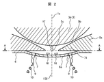
- FIG. 2 is an enlarged cross-sectional view of the vicinity of the tip of the valve body 3 of the fuel injection valve 1 according to the first embodiment of the present invention.
- the main parts according to the present invention will be briefly described with reference to FIG.
- the valve portion 3b of the valve body 3 uses a ball valve.
- balls 3b for example, JIS standard ball bearing steel balls are used. This ball has a high roundness and has a mirror finish, and is suitable for enhancing sheet properties, and is low in cost due to mass production.
- a ball having a diameter of about 3 to 4 mm is used. This is to reduce the weight because it functions as a movable valve.
- the angle of the inclined surface (valve seat surface 5b) including the seat position in close contact with the valve body 3 is about 90 ° (80 ° to 100 °).
- This inclination angle is an optimum angle for polishing the vicinity of the seat position and increasing the roundness (the grinding machine can be used in the best condition), and maintains the above-mentioned seat property with the valve body 3 extremely high. It can be done.
- the nozzle body 5 having the inclined surface including the sheet position is increased in hardness by quenching, and unnecessary magnetism is removed by demagnetization treatment. With such a valve body configuration, it is possible to control the injection amount without fuel leakage. Moreover, the valve body structure excellent in cost performance can be provided.
- the nozzle plate 6 is extruded by a punch in a manufacturing process for forming a convex surface in order to form a downward convex shape.
- valve body 3 comes into contact with a valve seat surface 5b formed of a conical surface provided on a nozzle body (seat member) 5 joined to the casing 2 by welding or the like. Keep the seal of.
- the contact portion on the valve body 3 side is formed by a spherical surface, and the contact between the conical valve seat surface and the spherical surface is in a substantially line contact state.
- reference numeral 102 denotes a central axis (central axis) of the nozzle plate 6 and the valve body 3.
- the center shaft 102 coincides with the center axis 1a of the fuel injection valve.
- the position of the protruding portion 6a of the nozzle plate 6 that protrudes downward is coincident with the central axis 102 and the central axis 1a.
- FIG. 3 is a view of the nozzle plate 6 of the fuel injection valve 1 according to the first embodiment of the present invention as viewed from the valve body 3 side.
- FIG. 3 is a plan view seen from the AA section of FIG.
- the axis extending through the center O of the nozzle plate 6 in the horizontal direction in FIG. 3 is the X axis (virtual X axis), and the axis extending through the center O of the nozzle plate 6 in the vertical direction in FIG. To do.
- the X axis and the Y axis intersect with each other at the center O with the center O as the origin.
- FIG. 3 shows a virtual orthogonal coordinate system formed by the X axis and the Y axis and the nozzle holes 7a, 7b, 7c, 7d, 7e, 7f, 7a ′, 7b ′, 7c ′, 7d ′, 7e ′, 7f ′.
- FIG. 4 is a projection view (plan view) projected onto a virtual plane perpendicular to the central axis 102 and the central axis 1a.
- the following description is based on the configuration on the virtual plane except for the description distinguished from the configuration on the virtual plane.
- the inclination direction of the central axis 71 and the arrow 11, which will be described below, the interval L, the interval l between the nozzle holes, and the like are also described based on the projections projected on the virtual plane.
- X> 0 and Y> 0 be the first quadrant
- X ⁇ 0 and Y> 0 be the second quadrant
- X ⁇ 0 and Y ⁇ 0 be the third quadrant
- X> 0 and Y ⁇ 0 be the fourth quadrant.
- the nozzle holes 7a, 7b, 7c are arranged in the first quadrant
- 7d ′, 7e ′, 7f ′ the fourth in the third quadrant.
- the nozzle holes 7d, 7e, 7f are arranged in the quadrant.
- the nozzle hole group composed of the nozzle holes 7a, 7b, 7c, 7d, 7e, 7f is composed of the first nozzle hole group 7A, the nozzle holes 7a ′, 7b ′, 7c ′, 7d ′, 7e ′, 7f ′.
- This nozzle hole group is defined as a second nozzle hole group 7B.
- the nozzle holes 7a, 7b, 7c, 7d, 7e, 7f of the first nozzle hole group 7A inject fuel in one direction as a whole to form a first fuel spray.
- the first injection hole group 7A is divided into a first group 7A1 including injection holes 7a, 7b, and 7c and a second group 7A2 including injection holes 7d, 7e, and 7f with the X axis as a boundary.
- the second injection hole group 7B is divided into a first group 7B1 including injection holes 7a ', 7b', and 7c 'and a second group 7B2 including injection holes 7e' and 7f 'with the X axis as a boundary.
- injection holes 7a, 7b, 7c, 7d, 7e, 7f, 7a ′, 7b ′, 7c ′, 7d ′, 7e ′, 7f ′ are simply the injection holes (fuel injection holes). ) Call 7 and explain.
- the positive direction of the X axis coincides with the overall (overall) injection direction of the spray injected from the nozzle holes 7a to 7f arranged in the first nozzle hole group 7A, and the negative direction of the X axis is This coincides with the overall (overall) spraying direction of the spray sprayed from the nozzle holes 7a ′ to 7f ′ arranged in the second nozzle hole group 7B.
- Arrow 11 indicates the inclination direction of each nozzle hole 7. That is, when the central axis 71 (see FIG. 2) of each nozzle hole 7 is projected onto the AA cross section (plane), the projection line of the central axis 71 overlaps the arrow 11.
- the tip side of the arrow 11 is the downstream side in the fuel flow direction, that is, the outlet side of the injection hole 7.
- the nozzle holes 7a, 7b, 7c of the first nozzle hole group 7A are arranged so that the interval between adjacent nozzle holes (distance between the centers of the inlet surfaces) l is equal.
- the nozzle holes 7a, 7b, and 7c are arranged on the circumference of an arrangement circle 80 centered on the center (the origin of the virtual orthogonal coordinate system) O of the nozzle plate 6. For this reason, the nozzle holes 7a, 7b, and 7c are arranged at equal angular intervals with the point O as the center.
- the nozzle holes 7d, 7e, 7f of the first nozzle hole group 7A are arranged so that the interval (distance between the centers of the inlet surfaces) 1 between adjacent nozzle holes is equal.
- the nozzle holes 7d, 7e, and 7f are arranged on the circumference of an arrangement circle 80 centering on the center O of the nozzle plate 6. For this reason, the nozzle holes 7d, 7e, and 7f are arranged at equal angular intervals with the point O as the center.
- the nozzle holes 7a, 7b, and 7c of the first group 7A1 and the nozzle holes 7d, 7e, and 7f of the second group 7A2 are located in front of the fuel injection direction, and the center axis 71 ( Inclined so that the arrow 11) is close.
- the nozzle hole 7c is arranged closest to the X axis and is arranged closest to the second group 7A2.
- the nozzle hole 7d is arranged closest to the X axis and is arranged closest to the first group 7A1.
- the distance L between the adjacent nozzle holes 7c and 7d across the X axis is greater than the distance l between the nozzle holes 7a, 7b and 7c and the distance l between the nozzle holes 7f, 7e and 7d in the first nozzle hole group 7A. Is also getting bigger.
- the interval L is the center of the inlet surface (inlet opening surface) in the nozzle holes 7a, 7b, 7c of the first group 7A1 and the center of the inlet surface (inlet opening surface) in the nozzle holes 7d, 7e, 7f of the second group 7A2. Is the smallest of the distances between.
- the inter-group nozzle hole that is the smallest among the inter-group nozzle hole distances formed between the centers of the inlet surfaces of the nozzle holes The distance L between the plurality of nozzle holes 7a, 7b, 7c (7a ', 7b', 7c ') constituting the first group 7A1 (7B1) is 7a, 7b, 7c (7a', 7b).
- the intra-group inter-hole distance 1 formed between the centers of the inlet faces and a plurality of nozzle holes 7d, 7e, 7f (7d ', 7e') constituting the second group 7A2 (7B2), 7f ′) between the nozzle holes 7d, 7e, 7f (7d ′, 7e ′, 7f ′). It is set larger than the group injection hole distance l as the largest of the group injection hole distance l comprised between centers.
- the distance between the groups in each of the nozzle hole groups 7A and 7B is the same in each of the nozzle hole groups 7A and 7B.
- the distance between the first groups 7A1 and 7B1 and the second groups 7A2 and 7B2 is the distance between the centers of the entrance surfaces of the two nozzle holes arranged closest to each other.
- the nozzle holes 7a ′, 7b ′, 7c ′, 7d ′, 7e ′, and 7f ′ pass through the nozzle holes 7a, 7b, 7c, 7d, 7e, and 7f through the Y axis and are perpendicular to the paper surface of FIG.
- the plane is symmetrical with respect to a plane including the Y axis and the central axis 1a and a plane passing through the Y axis and perpendicular to the X axis.
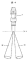
- FIG. 4 is a view when the spray form of the fuel injection valve according to the first embodiment of the present invention is viewed from the Y-axis direction.
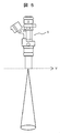
- FIG. 5 is a view when the spray form of the fuel injection valve according to the first embodiment of the present invention is viewed from the X-axis direction. 4 shows the state of spraying when viewed from the ⁇ Y direction, and FIG. 5 shows the state of spraying when viewed from the + X direction.
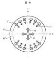
- FIG. 6 is a view of the nozzle plate 6 ′ in the fuel injection valve of the first comparative example with the present invention as seen from the valve body side.
- the comparative example of FIG. 6 shows a nozzle plate 6 ′ that is inclined so that the outlet surface of the nozzle hole 7 ′ is located on the center side of the nozzle plate 6 ′ with respect to the inlet surface. That is, the nozzle plate 6 ′ in which the nozzle hole 7 ′ is inclined so as to face the direction 18 of the fuel flow flowing into the nozzle hole 7 ′ is shown.
- all the nozzle holes 7 ' are arranged on the circumference of an arrangement circle 80' centering on the center O 'of the nozzle plate 6'.
- the flow direction 11 ′ of the fuel flowing in the nozzle hole 7 ′ and the direction 18 of the fuel flow before flowing into the nozzle hole 7 ′ are shown.
- the nozzle hole 7 ′ is inclined so that and overlap in the opposite direction. In this case, the central axis 73 (see FIG. 7) of the nozzle hole 7 ′ overlaps the fuel flow direction 18.
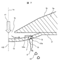
- FIG. 7 is a view for explaining the flow field in the vicinity of the injection hole 7 ′ of the fuel injection valve of the first comparative example with the present invention.
- the fuel 17 that has passed through the opening 5c of the fuel passage collides with the upper surface of the nozzle plate 6 ', and forms a fast flow 18 along the wall surface of the nozzle plate 6'. Then, it flows into the nozzle hole 7 '.
- the fuel 103a flowing into the nozzle hole 7 ′ collides with the wall surface 72 of the nozzle hole 7 ′, and the central axis 73 of the nozzle hole 7 ′.
- a flow 103b having a large velocity component is induced in a plane perpendicular to the above. That is, the flow 103b has a large velocity component in the circumferential direction and the radial direction of the nozzle hole 7 '.
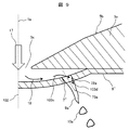
- the nozzle hole 7 ′′ in order to form a spray in two directions, is inclined in a direction away from the center of the nozzle plate 6 ′′ from the inlet surface to the outlet surface of the nozzle hole 7 ′′. It was. In this case, as shown in FIG. 9, the inclination direction of the injection hole 7 ′′ is not optimal with respect to the main flow direction 18, and the force with which the fuel 103c flowing into the injection hole 7 ′′ collides with the injection hole wall surface 72a is weak. Further, the flow velocity in the plane perpendicular to the central axis 73a of the nozzle hole 7 ′′ is reduced, and the flow in the nozzle hole 7 ′′ follows a nozzle hole inclination like the flow 103d.
- the fuel flow has a smaller in-plane velocity component and a larger axial velocity component.
- the velocity components in the circumferential direction and the radial direction in the nozzle hole 7 ′′ are small, the liquid film 9a of the fuel is difficult to spread downstream of the nozzle hole 7 ′′, and the particle size of the droplet 10a split from the liquid film 9a is small. There was a problem to get worse.
- the maximum of the distance between the nozzle holes 7a to 7c in the first group and the maximum distance between the nozzle holes 7e to 7f in the second group is made larger than the distance between the nozzle holes, so that the nozzle holes 7a To 7f and 7a ′ to 7f ′ are arranged.
- the nozzle holes 7a to 7f and 7a ′ to 7f ′ are inclined so that the exit surface approaches the one plane including the central axis 102 of the nozzle plate 6 with respect to the entrance surface. Yes.
- This plane is a plane including the central axis 102 and the X axis.
- FIG. 10 is an enlarged view of the vicinity of the injection hole 7c when the nozzle plate 6 of the fuel injection valve 1 according to the first embodiment of the present invention is viewed from the valve body 3 side.
- the nozzle holes 7a and 7b have the same concept as the nozzle hole 7c described below.
- the nozzle holes 7d, 7e, and 7f are symmetrical with the nozzle holes 7a, 7b, and 7c with respect to a plane that passes through the X axis and is perpendicular to the paper surface (a plane that passes through the X axis and is perpendicular to the Y axis).
- the axis passing through the center 7cio of the inlet face 7ci of the nozzle hole 7c and parallel to the X axis is taken as the X 'axis
- the axis passing through the center 7cio of the inlet face 7ci of the nozzle hole 7c and parallel to the Y axis is taken as the Y' axis.
- a circle passing through the center 7cio of the entrance surface 7ci of the nozzle hole 7c and centering on the origin O of the X and Y axes is defined as an arrangement circle 80.
- the inclination angle of the nozzle hole 7c is set in the range of ⁇ a in FIG. That is, the nozzle hole 7c is directed to an angle range (X ′> 0 and Y ′ ⁇ 0 angle range) formed by the X ′> 0 portion of the X ′ axis and the Y ′ ⁇ 0 portion of the Y ′ axis. To tilt. At this time, the angle range does not include on the X ′ axis and the Y ′ axis.
- the center of the outlet surface of the nozzle hole 7c is located in the range of X '> 0 on the X' axis and in the range of Y ' ⁇ 0 on the Y' axis. Thereby, the spray of two directions can be formed and atomization can be accelerated
- the setting range of the center position of the exit surface of the nozzle hole 7c does not include on the X ′ axis and the Y ′ axis.
- this injection direction is a positive direction along the X axis of FIG. Head for.
- this injection direction is plotted on the X axis in FIG. Along the negative direction.
- the nozzle hole 7c becomes the first nozzle hole.
- the first fuel spray formed by the group 7A can be largely inclined with respect to the injection direction. Thereby, the inclination angle of the injection hole 7c can be made larger with respect to the flow direction of the fuel flowing into the injection hole 7c.
- the injection direction of the nozzle hole 7c is as shown in FIG.
- the direction is parallel to a plane passing through the Y axis and perpendicular to the paper surface of FIG. 10 (a plane passing through the Y axis and perpendicular to the X axis). For this reason, the spray injected from the first nozzle hole group 7A and the spray injected from the first nozzle hole group 7B are injected in parallel.
- FIG. 10 shows a plane passing through the Y axis and perpendicular to the X axis.
- the center position of the outlet face of the injection hole 7 c is arranged so that the first fuel spray and the second fuel spray are separated in the front (downstream side) in the injection direction.
- the setting range does not include the Y ′ axis (that is, the Y ′ axis is not included in the tilt direction of the nozzle hole 7c).
- the overall (overall) spray direction of the spray sprayed from the nozzle holes 7a to 7f arranged in the first nozzle hole group 7A is parallel to the Y axis in FIG.
- the direction towards the direction, The overall (overall) spray direction of the spray sprayed from the nozzle holes 7a ′ to 7f ′ arranged in the second nozzle hole group 7B is parallel to the Y axis in FIG. 3 and in the negative direction of the Y axis.
- a two-way spray similar to that shown in FIG. 4 can be formed.
- the Y′-axis can be included in the set range of the center position of the exit surface of the nozzle hole 7c (that is, the Y′-axis can be included in the inclination direction of the nozzle hole 7c).
- the inclination angle of the nozzle hole 7c may be set to be limited to the range of ⁇ b. That is, the nozzle hole 7c is inclined so as to face an angle range formed by the tangent 80a at the nozzle hole center position of the arrangement circle 80 and the Y ' ⁇ 0 portion of the Y' axis. This angle range is an angle range configured as Y ′ ⁇ 0. At this time, the center of the exit surface of the nozzle hole 7c is located in a range sandwiched between the tangent 80a and the Y ' ⁇ 0 portion of the Y' axis in a range where Y ' ⁇ 0. Thereby, atomization can be further promoted. In this case, the nozzle hole 7c may be inclined along the tangent line 80a. At this time, the center of the exit surface of the nozzle hole 7c is arranged on the tangent line 80a.
- the angle range ⁇ b formed by the tangent 80a and the Y ′ ⁇ 0 portion of the Y ′ axis substantially matches the range where X ′> 0 and the inner side of the arrangement circle 80. Therefore, the nozzle hole 7 c may be inclined in a range where X ′> 0 and in the range inside the arrangement circle 80. In this case, the center of the exit surface of the nozzle hole 7 c is located in a range where X ′> 0 and inside the arrangement circle 80.
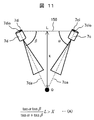
- FIG. 11 is a diagram schematically showing the relationship between the inclination angle of the nozzle hole and the spray interference distance in the BB cross section of FIG.
- a combination of nozzle holes arranged so that the central axes 71 intersect each other can be made between the nozzle holes 7a to 7c of the first group 7A1 and the nozzle holes 7d to 7f of the second group 7A2.
- the nozzle hole 7c and the nozzle hole 7d are a combination of nozzle holes having the shortest center-to-center distance L among the combinations of nozzle holes arranged so that the central axes 71 intersect each other.
- the inclination of the injection hole 7c with respect to the horizontal direction is ⁇
- the inclination of the injection hole 7d with respect to the horizontal direction is ⁇
- the distance between the centers of the injection holes 7c and 7d is L
- the central axis 7ca of the injection hole 7c is Q is the point where the central axis 7da of the nozzle hole 7d intersects
- the straight line 150 connecting the center 7cio of the inlet surface 7ci of the nozzle hole 7c and the center 7dio of the inlet surface 7di of the nozzle hole 7d is the height of the point Q.
- ⁇ and ⁇ are set so that X is 2 mm or more, the influence of spray interference can be suppressed and atomization is promoted. Furthermore, X is more preferably 5 mm or more, and further preferably X is 7 mm or more.
- the nozzle hole 7a (7f) located at the end of the first nozzle hole group 7A on the circumference of the arrangement circle 80 and the circle of the arrangement circle 80 The distance between the nozzle holes 7a ′ (7f ′) located at the end of the second nozzle hole group on the circumference (the distance between the centers of the inlet surfaces) is the distance between the nozzle holes 7a to 7f in the first nozzle hole group 7A. It is larger than (the distance between the centers of the inlet surfaces) and the interval between the nozzle holes 7a ′ to 7f ′ (the distance between the centers of the inlet surfaces) in the second nozzle hole group 7B.
- the inter-group nozzle hole distance L that is the smallest in the first nozzle hole group 7A and the inter-group nozzle hole distance L that is the smallest in the second nozzle hole group 7B are the first The two closest nozzle holes 7a (7f) and 7a between the plurality of nozzle holes 7a to 7f constituting the nozzle hole group 7A and the plurality of nozzle holes 7a 'to 7f' constituting the second nozzle hole group 7B
- the distance between the centers of the inlet faces of the respective nozzle holes 7 is set so as to be larger than the distance between the centers of the inlet faces of '(7f') '.
- two nozzle holes having a large center-to-center distance (L) between the inlet surfaces exist in the same nozzle hole group.
- L center-to-center distance
- the second injection hole on the inlet surface of the injection hole 7a located at the end of the first injection hole group 7A on the circumference of the arrangement circle 80 and the circumference of the arrangement circle 80 may be larger than the center-to-center distance l between the entrance surfaces of the other nozzle holes.
- the distance between the centers of the holes 7f ′ and the inlet surface may be larger than the distance l between the centers of the inlet surfaces of the other nozzle holes.
- the space for arranging the nozzle holes 7 on the circumference of the arrangement circle 80 is limited. It has been. Therefore, the center-to-center distance between the inlet surface of the nozzle hole 7a and the inlet surface of the nozzle hole 7a ′ and the center-to-center distance between the inlet surface of the nozzle hole 7f and the inlet surface of the nozzle hole 7f ′ are smaller than the center-to-center distance L. It is preferable to do.
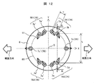
- FIG. 12 is a view of the nozzle plate 6 of the fuel injection valve 1 according to the second embodiment of the present invention as viewed from the valve body 3 side. Note that the same components as those in the first embodiment are denoted by the same reference numerals and description thereof is omitted.
- the central axis (injection direction) of the nozzle hole 7c has the largest X coordinate value in the first nozzle hole group 7A. Further, since the central axis (injection direction) of the injection hole 7c exists on a plane that passes through the X axis and is perpendicular to the Y axis, the other injection holes 7a, 7b, 7d, and 7e of the first injection hole group 7A. Does not intersect the central axis.
- the central axis (injection direction) of the nozzle hole 7c ′ of the second nozzle hole group 7B is the other nozzle holes 7a ′, 7b of the second nozzle hole group 7B. It does not intersect with the central axes of ', 7d' and 7e '. Therefore, the nozzle hole 7c and the nozzle hole 7c 'do not require special consideration of the distance from other nozzle holes.
- the central axis (injection direction) of the injection hole 7c ′ of the second injection hole group 7B intersects with the central axes of the other injection holes 7a ′, 7b ′, 7d ′, and 7e ′ of the second injection hole group 7B. You may do it.
- the injection hole is formed such that the position where the central axis of the injection hole 7c ′ intersects with the central axis of the other injection holes 7a ′, 7b ′, 7d ′, and 7e ′ is separated to some extent from the outlet of each injection hole. It is necessary to consider the distance between the two or the inclination angle of the nozzle hole.
- the nozzle holes 7a, 7b, 7d, and 7e and the nozzle holes 7a ', 7b', 7d ', and 7e' are nozzle holes that are arranged in plane symmetry with respect to a plane that passes through the Y axis and is perpendicular to the X axis. Thus, it is necessary to set the center-to-center distance of the entrance surface as described above for the nozzle holes arranged with the X axis interposed therebetween.
- the nozzle holes 7c and 7c ′ can easily form two-way sprays, and the nozzle holes 7a, 7b, 7d, 7e, 7a ′, 7b ′, 7d ′, 7e ′ can promote atomization as in the first embodiment.
- the nozzle holes 7c and 7c ′ share the roles to be played, such as the formation of two-way spray, and the nozzle holes 7a, 7b, 7d, 7e, 7a ′, 7b ′, 7d ′, and 7e ′ promote atomization. be able to. By doing in this way, there exists an effect that control of a spray angle becomes easy.
- FIG. 13 is an enlarged cross-sectional view of the vicinity of the tip 3b of the valve body 3 of the fuel injection valve 1 according to the third embodiment of the present invention.
- symbol is attached
- the shape of the nozzle plate 6 is described as the downward convex shape 6a.
- the vicinity of the center of the nozzle plate 6 (the portion facing the opening 5c in the vicinity of the central axis 102) has a downward convex shape 6a, and the portion where the nozzle hole 7 is processed has a planar structure.
- Other configurations are the same as those in the first embodiment or the second embodiment.
- the fuel that has passed between the valve seat surface 5b and the tip 3b of the valve body 3 passes through the opening 5c and collides with the upper surface of the nozzle plate 6 from the direction of the arrow 17. Thereafter, as indicated by an arrow 18, the gas flows radially outward from the center of the nozzle plate 6 along the surface of the nozzle plate. At this time, the vicinity of the center of the nozzle plate 6 has a downward convex shape 6a, so that the fuel speed near the surface of the nozzle plate increases. Then, after passing through the nozzle hole 7, a liquid film 9 is formed and split into droplets 10 due to instability due to surface tension waves and shearing force with air, thereby achieving atomization of fuel.
- the speed near the surface of the nozzle plate 6 can be increased, and atomization can be promoted.
- the installation part of the nozzle hole 7 into a plane structure, the processing accuracy of the nozzle hole 7 is improved, the control of the direction in which the fuel is sprayed is facilitated, and the distance between the nozzle plate 6 and the seal member 5a is increased.
- the volume of the space surrounded by the nozzle plate 6, the valve seat surface 5b, and the valve body 3 can be reduced. By reducing this volume, it becomes possible to accurately spray a target amount of fuel.
- the portion facing the opening 5 c in the vicinity of the central axis 102 of the nozzle plate 6 is configured as a plane. That is, the entire nozzle plate 6 is a flat surface, and the downward convex shape 6a is not formed.
- a concave portion 6b is formed extending from the portion facing the opening 5c in the vicinity of the central axis 102 toward the radially outer side (outer diameter side).
- the nozzle hole 7 which an entrance surface opens is provided in the bottom face of the recessed part 6b.
- Other configurations are the same as those in the first to third embodiments.
- FIG. 15 is a view of the nozzle plate 6 of the fuel injection valve 1 according to the fifth embodiment of the present invention as viewed from the valve body 3 side.
- the same components as those in the first to third embodiments are denoted by the same reference numerals and description thereof is omitted.
- Example 1 the configuration in which all the nozzle holes 7 are arranged on the same arrangement circle has been described.
- the nozzle holes 7 are arranged on a plurality of arrangement circles 80 and 81.
- nozzle holes 7a, 7b, and 7c are provided as the first group 7A1 of the first nozzle hole group 7A.
- nozzle holes 7d, 7e, and 7f are provided as the second group 7A2 of the first nozzle hole group 7A.
- the distance between the groups in the nozzle hole group is the distance L between the nozzle holes 7b and 7b ′ and the nozzle holes 7e and 7e ′, and the nozzle holes 7a to 7c and 7d constituting each group in each nozzle hole group.
- the nozzle holes 7 are arranged so that L is larger than the maximum distance between the nozzle holes (the distance between the centers of the inlet surfaces of the respective nozzle holes) of .about.7f, 7a ′ to 7c ′, and 7d ′ to 7f ′.
- the arrangement space of the nozzle holes on one arrangement circle 80 is reduced. For this reason, a large number of nozzle holes 7 can be arranged by dispersing the nozzle holes 7 in a plurality of arrangement circles 80 and 81. Alternatively, it is possible to prevent a large number of nozzle holes from being concentrated in a narrow space, so that the strength of the nozzle plate 6 does not need to be reduced.
- the nozzle holes 7c and 7c 'of the second embodiment and the nozzle plate 6 of the third and fourth embodiments may be applied.
- this invention is not limited to each above-mentioned Example, Various modifications are included.
- the above-described embodiments have been described in detail for easy understanding of the present invention, and are not necessarily limited to those having all the configurations.
- a part of the configuration of one embodiment can be replaced with the configuration of another embodiment, and the configuration of another embodiment can be added to the configuration of one embodiment.
- SYMBOLS 1 Fuel injection valve, 1a ... Center axis of fuel injection valve, 2 ... Casing, 2a ... Fuel supply port, 3 ... Valve body, 4 ... Anchor, 5 ... Nozzle body, 5b ... Valve seat surface, 5c ... Opening part, 6 ... Nozzle plate, 6a ... Down convex shape, 7, 7a, 7b, 7c, 7d, 7e, 7f, 7a ', 7b', 7c ', 7d', 7e '... Injection hole, 11 ... Inclination direction of injection hole DESCRIPTION OF SYMBOLS 12 ... Spring, 13 ... Spring adjuster, 14 ... Electromagnetic coil, 15 ... Core, 16 ...
Landscapes
- Engineering & Computer Science (AREA)
- Chemical & Material Sciences (AREA)
- Combustion & Propulsion (AREA)
- Mechanical Engineering (AREA)
- General Engineering & Computer Science (AREA)
- Fuel-Injection Apparatus (AREA)
Abstract
本発明の目的は、噴孔内壁面への燃料の衝突力を大きくすることができ、十分な微粒化を実現できる燃料噴射弁を提供することにある。弁体の中心軸線方向に対して直交する仮想平面において、第1噴孔群7Aを構成する複数の噴孔7a~7f、7a'~7f'は、噴孔入口面(実線)から噴孔出口面(点線)に向かう噴孔中心軸が、仮想X軸と仮想Y軸とからなる仮想直交座標系の原点Oと噴孔入口面の中心とを結ぶ直線とは異なる方向に向かって形成されると共に、噴孔入口面の中心に対して噴孔出口面の中心が仮想X軸に近接した位置に形成される。
Description
本発明は、ガソリンエンジン等の内燃機関に用いられる燃料噴射弁であって、弁体が弁座と当接することで燃料の漏洩を防止し、弁体が弁座から離れることによって噴射を行う燃料噴射弁に関する。
近年、自動車の排ガス規制が強化されてきている。この排ガス規制強化に対応して、自動車用内燃機関に搭載される燃料噴射弁の噴霧には、微粒化と、正確な噴射方向とが求められている。噴霧の微粒化により、自動車エンジンの低燃費化を実現できる。また、噴霧を狙い通りの位置(例えば、吸気弁の2方向)へ噴射することで、吸気管等の壁面への噴霧の付着を抑制することができる。
例えば、特許文献1には、ペネトレーション性が良好な2本の噴霧を形成することのできる燃料噴射弁について記載されている。特許文献1の燃料噴射弁では、複数の燃料噴孔を、弁孔の軸線を含む一平面を境にして第1及び第2組の燃料噴孔群に分けると共に、これら第1及び第2組の燃料噴孔群からの噴射燃料により2本の噴霧フォームを形成するようにした燃料噴射弁において、第1及び第2組の全ての燃料噴孔を同一直径に形成すると共に、各組の両外側に位置する燃料噴孔の第2中心線を、インジェクタプレート前方に向かって各組の中央もしくはその近傍に位置する燃料噴孔の第1中心線に対し近づくように傾けている(要約参照)。
一般的なノズルプレートにおける微粒化の主なメカニズムは以下の通りとなっている。
燃料が燃料噴孔(以下、噴孔と呼ぶ)に流れ込む際に、燃料は噴孔の内壁に衝突し、噴孔の中心軸(中心線)に対して垂直方向の面内に大きな速度成分を持つ流れが誘起される。
すなわち、噴孔の周方向および半径方向の速度成分が大きくなる。以下、この速度成分を面内速度成分と呼ぶ。一方、噴孔の中心軸方向の速度成分を軸方向速度成分と呼ぶ。
燃料が燃料噴孔(以下、噴孔と呼ぶ)に流れ込む際に、燃料は噴孔の内壁に衝突し、噴孔の中心軸(中心線)に対して垂直方向の面内に大きな速度成分を持つ流れが誘起される。
すなわち、噴孔の周方向および半径方向の速度成分が大きくなる。以下、この速度成分を面内速度成分と呼ぶ。一方、噴孔の中心軸方向の速度成分を軸方向速度成分と呼ぶ。
この面内速度成分によって、噴孔下流で燃料が広がり易くなり、微粒化が促進される。
従って、この面内速度成分の大きさが噴霧の微粒化に大きく影響する。つまり、噴孔内壁面への衝突力が大きいほど、面内速度成分は大きくなり、微粒化が促進されることになる。
従って、この面内速度成分の大きさが噴霧の微粒化に大きく影響する。つまり、噴孔内壁面への衝突力が大きいほど、面内速度成分は大きくなり、微粒化が促進されることになる。
しかしながら、特許文献1に記載されている燃料噴射弁では、複数の噴孔を2つの噴孔群(第1及び第2組の燃料噴孔群)に分け、さらに各噴孔群において、両外側以外の噴孔は、中心軸の延長線が平行に、かつ噴射方向に向かって弁座部材の弁孔の軸線を通りY方向(2つの噴孔群の境界方向)に延びる平面から離れる方向に傾斜するように配置されている。この場合、噴孔の入口に向かう燃料の流れ方向と噴孔の傾斜方向(中心軸の方向)との間の角度が小さくなる。このため、噴孔内壁面への燃料の衝突力(押し付け力)が小さくなり、噴霧の微粒化に課題があった。
本発明の目的は、噴孔内壁面への燃料の衝突力を大きくすることができ、十分な微粒化を実現できる燃料噴射弁を提供することにある。
上記課題を解決するために、代表的な本発明の燃料噴射弁の一つは、
中心軸線方向に変位可能に構成された弁体と、前記弁体と協働して燃料通路を開閉する弁座と、前記弁座よりも下流側に設けられ前記燃料通路を通過した燃料を外部に噴射する複数の噴孔と、を備え、前記複数の噴孔の少なくとも一部の複数の噴孔によって構成される第1噴孔群の前記複数の噴孔から噴射される燃料が全体的に第1の噴射方向を指向する第1燃料噴霧を形成する燃料噴射弁において、
前記中心軸線方向に対して直交する仮想平面に、前記第1噴孔群を構成する前記複数の噴孔と前記第1燃料噴霧が指向する前記第1の噴射方向とを投影すると共に、前記第1の噴射方向に沿う仮想X軸と前記仮想X軸に直交する仮想Y軸とを有し、原点が前記中心軸線を前記仮想平面に投影した投影中心点に一致する仮想直交座標系を前記仮想平面に仮想した場合に、
前記仮想平面において、前記第1噴孔群を構成する前記複数の噴孔は、前記噴孔の入口面から出口面に向かう噴孔中心軸が、前記仮想直交座標系の前記原点と前記入口面の中心とを結ぶ直線とは異なる方向に向かって形成されると共に、前記入口面の中心に対して前記出口面の中心が前記仮想X軸に近接した位置に形成される。
本発明によれば、噴孔内壁面への燃料の衝突力を大きくすることができ、微粒化を促進することが可能な燃料噴射弁を提供することができる。
上記した以外の課題、構成及び効果は、以下の実施形態の説明により明らかにされる。
以下、図面を用いて、本発明の一実施例を説明する。以下の説明では、図1に基づいて上下方向を定義する。この上下方向は燃料噴射弁1がエンジンに実装される際の上下方向とは関係がない。また、燃料噴射弁1の燃料供給口2a側(上端側)を基端側、ノズルプレート6側(下端側)を先端側と呼んで説明する。これは、燃料供給口2a側が図示しない燃料配管に接続されて、燃料の供給を受ける側であることに基づいている。
以下、本発明の第一実施例を、図1~図11を用いて説明する。
図1は、本発明の第1実施例に係る燃料噴射弁1の断面図である。
図1において、燃料噴射弁1は、例えば自動車のエンジンとして利用される内燃機関に燃料を供給するものである。ケーシング2は、プレス加工や切削加工等により、細長く薄肉部を有する円筒形状に形成される。ケーシング2は、両端部の中間部に段差部2bを有する形状で、燃料噴射弁1のほぼ基端部から先端部まで一体構造を成す円筒状に形成される。素材はフェライト系ステンレス材料にチタンのような柔軟性のある材料を加えたもので、磁性特性を有している。
ケーシング2の一端面(上端面)には、燃料供給口2aが設けられており、他端面(下端面)には複数の燃料噴射孔(噴孔)を有するノズルプレート6が設けられている。ノズルプレート6は、ノズル体5に固着されている。
ノズルプレート6は燃料を噴射するための孔7(以下、噴孔と呼ぶ)を有する(図3参照)。図1のケーシング2の外側には、電磁コイル14と電磁コイル14を包囲する磁性材のヨーク16が設けられている。一方内側には、固定コア15と、アンカー4と、弁体3と、ノズル体5と、ノズルプレート6とが設けられている。
固定コア15はケーシング2内に挿入された後に電磁コイル14の内側に配置される。
アンカー4は、固定コア15の先端側端面との間に空隙を有して、先端側端面と対向する。またアンカー4は、後述する弁体3と共に軸方向(中心軸線1a方向)に変位することが可能なように組み付けられている。なおアンカー4は、磁性材料からなる金属粉末をMIM(Metal Injection Molding)等の工法により射出成型して製造される。
弁体3は、アンカー4と一体に形成されており、中心軸102方向(図2参照)に延材する中空のロッド部3aと、ロッド部3aの先端部に固着されたボール弁部3bとを有する。弁体3は、アンカー4とは別部材として構成されてもよい。弁体3とアンカー4とは可動子を構成し、中心軸102に沿う方向に変位可能に構成されている。
ノズル体5は、弁体3の先端側でノズルプレート6の基端側に設けられている。ノズル体5は、ケーシング2の先端部に挿入され、ケーシング2に溶接により固設されている。
弁体3の先端(ボール弁部3b)が着座する弁座面5bが形成されている。
弁体3の先端(ボール弁部3b)が着座する弁座面5bが形成されている。
弁座面5bとボール弁部3bとの相互に当接する部位はシート部を構成し、ボール弁部3bが弁座面5bに当接することにより燃料通路が閉じられ、ボール弁部3bが弁座面5bから離れることにより燃料通路が開かれる。すなわち、弁体3と弁座面(弁座)5bとは協働してシート部の燃料通路を開閉する。なお、弁座面5bのシート部を弁座と呼ぶ場合もある。本実施例では、弁座面5bとシート部とを特に区別する必要はなく、弁座は弁座面5b或いはシート部のいずれであってもよい。
ノズルプレート6は、ノズル体5の先端側端面に配設されている。ノズルプレート6には、厚み方向に貫通して形成された複数の噴孔7が設けられている。噴孔7は、弁座面5bよりも下流側に設けられ、シート部の燃料通路を通過した燃料を外部に噴射する。ノズルプレート6はノズル体5と接する面を溶接により接合されている。
図1において、コア15の中心部を貫通する貫通孔の内部には、弾性部材としてのスプリング12が配設されている。スプリング12は、弁体3の弁部3bの先端(シート部)をノズル体5の弁座面5bのシート部に押し付ける力(付勢力)を与える。このスプリング12の燃料供給口2a側(アンカー4とは反対側)には、スプリング12に連続して、スプリング12の押し付け力を調整するスプリングアジャスタ13が配設されている。
また、燃料供給口2aには、フィルタ20が配設されており、燃料に含まれる異物を除去する。さらに燃料供給口2aの外周には、供給される燃料をシールするためのOリング21が取り付けられている。また、燃料供給口2aの近傍には、樹脂カバー22が設けられている。樹脂カバー22は、例えば樹脂モールド等の手段によりケーシング2とヨーク16とを覆うように設けられている。樹脂カバー22は、電磁コイル14に電力を供給するためのコネクタ23を内設している。
プロテクタ24は、燃料噴射弁1の先端部に設けられた、例えば樹脂材料等よりなる筒状部材をなしていて、ケーシング2の先端側の外周面を覆っている。プロテクタ2の上端部には、ケーシング2の外周面より径方向外向きに突出したプランジ部24aが形成されている。また、Oリング25はケーシング2の先端側外周に装着されている。Oリング25はヨーク16とプロテクタ24のプランジ部24aとの間に抜き止め状態で配置されている。Oリング25は、例えばケーシング2(燃料噴射弁1)の先端側を、内燃機関の吸気管に設けられた取り付け部(図示しない)等に取り付けた場合に、燃料噴射弁1と取り付け部との間をシールするものである。
このように構成される燃料噴射弁1は、電磁コイル14が非通電状態であるときはスプリング12の押し付け力に起因して、弁体3の先端がノズル体5に密着する。このような状態では、弁体3とノズル体5の間に隙間、つまり燃料通路が形成されないので、燃料供給口2aから流入した燃料はケーシング2内部に留まる。
電磁コイル14に噴射パルスとしての電流を印可すると、磁性材よりなるヨーク16と、コア15と、アンカー4とで構成される磁気回路に磁束が発生する。アンカー4は、電磁コイル14の電磁力によって、コア15の下端面に接触するまで移動する。弁体3がアンカー4と共にコア15側に移動すると、弁体3の弁部3bとノズル体5の弁座面5bとの間に燃料通路が形成される。ケーシング2内の燃料は、弁部3bの周辺より流入した後、燃料噴射孔7(図2参照)から噴射される。
燃料噴射量の制御は、電磁コイル14に間欠的に印可する噴射パルスに応じて、弁体3(弁部3b)を軸方向に移動することにより、開弁状態と閉弁状態の切り替えのタイミングを調整することで行っている。
図2は、本発明の第1実施例に係る燃料噴射弁1の弁体3の先端の近傍を拡大した断面図である。本発明に係わる主要部品について、図2を用いて、簡潔に説明する。
図2に示されるように、弁体3の弁部3bはボール弁を使用している。ボール3bには、例えば、JIS規格品の玉軸受用鋼球を用いている。このボールは、真円度が高く鏡面仕上げが施されており、シート性を高めるのに好適であること、また、大量生産により低コストであること、等がその採用のポイントである。また、弁体として構成する場合は、ボールの直径は3~4mm程度のものを使用する。これは、可動弁として機能するので軽量化を図るためである。
また、ノズル体5において、弁体3と密着するシート位置を含む傾斜面(弁座面5b)の角度は90°程度(80°~100°)である。この傾斜角は、シート位置付近を研磨し、且つ真円度を高くするために最適な角度(研削機械をベストコンディションで使用できる)であり、上述した弁体3とのシート性を極めて高く維持できるものである。なお、シート位置を含む傾斜面を有するノズル体5は、焼入れによって硬度が高められており、また、脱磁処理により無用な磁気が除去されている。このような弁体構成により、燃料漏れのない噴射量制御が可能となる。また、コストパフォーマンスに優れた弁体構造を提供できる。
またノズルプレート6は、下凸形状にするために、凸面を形成するための製造工程において、パンチによる押し出しを行う。
燃料噴射弁1が閉弁状態にあるときには、弁体3はケーシング2に溶接などで接合されたノズル体(シート部材)5に設けられた円錐面からなる弁座面5bと当接することによって燃料のシールを保つようになっている。このとき、弁体3側の接触部は球面によって形成されており、円錐面の弁座面と球面との接触はほぼ線接触の状態になっている。
弁体3が上昇して弁体3とノズル体5に隙間が生じると、燃料は前記隙間を流れ出し、ノズル体5の開口部5cにて、矢印17の方向からノズルプレート6の上面に衝突する。
その後、矢印18のように、ノズルプレート6の中央からノズルプレート6の表面に沿って半径方向外側へ流れる。この際、ノズルプレート6は下凸形状となっているため、ノズルプレート6の表面付近の燃料の速度が大きくなる。そして、噴孔7を通過後、液膜9を形成し、表面張力波による不安定性や空気との剪断力により液滴10へと分裂して、燃料の微粒化が達成される。
その後、矢印18のように、ノズルプレート6の中央からノズルプレート6の表面に沿って半径方向外側へ流れる。この際、ノズルプレート6は下凸形状となっているため、ノズルプレート6の表面付近の燃料の速度が大きくなる。そして、噴孔7を通過後、液膜9を形成し、表面張力波による不安定性や空気との剪断力により液滴10へと分裂して、燃料の微粒化が達成される。
なお、図6において、102はノズルプレート6及び弁体3の中心軸(中心軸線)である。本実施例では、中心軸102は燃料噴射弁の中心軸線1aに一致している。ノズルプレート6の凸形状部6aの最も下方に突き出た位置は、中心軸102及び中心軸線1aに一致している。
本実施例の噴孔7の詳細形状について、図3を用いて説明する。図3は、本発明の第1実施例に係る燃料噴射弁1のノズルプレート6を弁体3側から見た図である。なお、図3は図2のA―A断面から見た平面図である。
ノズルプレート6の中心Oを通り図3の横方向に伸びる軸をX軸(仮想X軸)、ノズルプレート6の中心Oを通り図3の縦方向に伸びる軸をY軸(仮想Y軸)とする。X軸とY軸とは中心Oを原点とし、中心Oで垂直に交わる。図3は、X軸とY軸とがなす仮想直交座標系と噴孔7a、7b、7c、7d、7e、7f、7a’、7b’、7c’、7d’、7e’、7f’とを、中心軸102及び中心軸線1aに垂直な仮想平面上に投影した投影図(平面図)である。以下の説明は、特に仮想平面上での構成と区別した説明を除いて、この仮想平面上での構成に基づいている。以下で説明する中心軸71及び矢印11の傾斜方向や、間隔Lや、噴孔間の間隔lなども、仮想平面上に投影した投影図に基づいて説明している。
X>0かつY>0を第一象限、X<0かつY>0を第二象限、X<0かつY<0を第三象限、X>0かつY<0を第四象限とする。本実施例では、第一象限に噴孔7a、7b、7cが配置され、第二象限に噴孔7a’、7b’、7c’、第三象限に7d’、7e’、7f’、第四象限に噴孔7d、7e、7fが配置される。
噴孔7a、7b、7c、7d、7e、7fから構成される噴孔群を第1噴孔群7A、噴孔7a’、7b’、7c’、7d’、7e’、7f’から構成される噴孔群を第2噴孔群7Bとする。第1噴孔群7Aの噴孔7a、7b、7c、7d、7e、7fは、全体として一方向に燃料を噴射して第1燃料噴霧を形成する。第2噴孔群7Bの噴孔7a’、7b’、7c’、7d’、7e’、7f’は、全体として、第1噴孔群7Aとは異なる一方向に燃料を噴射して第2燃料噴霧を形成する。
第1噴孔群7Aは、X軸を境界として、噴孔7a、7b、7cからなる第1グループ7A1と、噴孔7d、7e、7fからなる第2グループ7A2とに分けられる。第2噴孔群7Bは、X軸を境界として、噴孔7a’、7b’、7c’からなる第1グループ7B1と、噴孔7e’、7f’からなる第2グループ7B2とに分けられる。
なお、噴孔7a、7b、7c、7d、7e、7f、7a’、7b’、7c’、7d’、7e’、7f’を特に区別する必要がない場合は、単に噴孔(燃料噴射孔)7と呼んで説明する。
図3では、X軸の正方向が第1噴孔群7Aに配置された噴孔7a~7fから噴射される噴霧の総体的(全体的)な噴射方向に一致し、X軸の負方向が、第2噴孔群7Bに配置された噴孔7a’~7f’から噴射される噴霧の総体的(全体的)な噴射方向に一致している。
矢印11は各噴孔7の傾斜方向を示している。すなわち、各噴孔7の中心軸71(図2参照)をA―A断面(平面)に投影すると、中心軸71の投影線は矢印11に重なる。なお、矢印11の先端側が燃料の流れ方向において下流側、即ち噴孔7の出口側となる。
噴孔7a、7b、7cは、噴孔出口面中心のX座標が噴孔入口面中心のX座標よりも大きくなる方向、かつ、噴孔出口面中心のY座標が噴孔入口面中心のY座標より小さくなる方向に、噴孔の中心軸71が傾いている。また噴孔7d、7e、7fは、噴孔出口面中心のX座標が噴孔入口面中心のX座標よりも大きくなる方向、かつ、噴孔出口面中心のY座標が噴孔入口面中心のY座標よりも大きくなる方向に、噴孔の中心軸71が傾いている。
すなわち、本実施例では、図3の仮想平面上において、第1噴孔群7Aの第1グループ7A1及び第2グループ7A2を構成する複数の噴孔7a~7fは、噴孔7a~7fの噴孔入口面(実線)から噴孔出口面(点線)に向かう噴孔の中心軸71(図2参照)が、仮想直交座標系の原点Oと噴孔入口面の中心とを結ぶ直線とは異なる方向に向かって形成される。さらに、噴孔7a~7fは、噴孔入口面の中心に対して噴孔出口面の中心がX軸に近接するように、噴孔の中心軸71が傾斜して形成される。
本実施例では、第1噴孔群7Aの噴孔7a、7b、7cは、隣り合う噴孔間の間隔(入口面の中心間距離)lが等しくなるように配置されている。また、噴孔7a、7b、7cは、ノズルプレート6の中心(仮想直交座標系の原点)Oを中心とする配置円80の円周上に配置されている。このため、噴孔7a、7b、7cは、点Oを中心として等しい角度間隔で配置されている。また第1噴孔群7Aの噴孔7d、7e、7fは、隣り合う噴孔間の間隔(入口面の中心間距離)lが等しくなるように配置されている。また、噴孔7d、7e、7fは、ノズルプレート6の中心Oを中心とする配置円80の円周上に配置されている。このため、噴孔7d、7e、7fは、点Oを中心として等しい角度間隔で配置されている。
第1グループ7A1の噴孔7a、7b、7cと第2グループ7A2の噴孔7d、7e、7fとは、燃料の噴射方向の前方において、ノズルプレート6から離れるほど、噴孔の中心軸71(矢印11)が近接するように傾斜している。
第1グループ7A1の噴孔7a、7b、7cのうち噴孔7cは、最もX軸に近接して配置され、最も第2グループ7A2に近接して配置されている。第2グループ7A2の噴孔7d、7e、7fのうち噴孔7dは、最もX軸に近接して配置され、最も第1グループ7A1に近接して配置されている。そして、X軸を挟んで隣り合う噴孔7cと7dとの間隔Lは、第1噴孔群7A内における噴孔7a、7b、7cの間隔l及び噴孔7f、7e、7dの間隔lよりも大きくなっている。
間隔Lは、第1グループ7A1の噴孔7a、7b、7cにおける入口面(入口開口面)の中心と第2グループ7A2の噴孔7d、7e、7fにおける入口面(入口開口面)の中心との間の距離の中で、最小の距離である。
すなわち、本実施例では、第1グループ7A1(7B1)を構成する複数の噴孔7a、7b、7c(7a’、7b’、7c’)と第2グループ7A2(7B2)を構成する複数の噴孔7d、7e、7f(7d’、7e’、7f’)との間で、各噴孔の入口面の中心間に構成されるグループ間噴孔間距離の中で最小となるグループ間噴孔間距離Lが、第1グループ7A1(7B1)を構成する複数の噴孔7a、7b、7c(7a’、7b’、7c’)の間で各噴孔7a、7b、7c(7a’、7b’、7c’)の入口面の中心間に構成されるグループ内噴孔間距離l、及び第2グループ7A2(7B2)を構成する複数の噴孔7d、7e、7f(7d’、7e’、7f’)の間で各噴孔7d、7e、7f(7d’、7e’、7f’)の入口面の中心間に構成されるグループ内噴孔間距離lの中で最大となるグループ内噴孔間距離lよりも大きく設定されている。
別の見方をすれば、各噴孔群7A、7B内におけるグループ間の距離(第1グループ7A1、7B1と第2グループ7A2、7B2との距離)が、各噴孔群7A、7Bにおいて各グループ7A1、7B1、7A2、7B2を構成する各噴孔7a~7c、7d~7f、7a’~7c’、7d’~7f’の噴孔間最大距離(各噴孔入口面の中心間距離の最大値)よりも大きくなるように、各噴孔が配置されることを意味する。ここで、第1グループ7A1、7B1と第2グループ7A2、7B2との距離は、各グループ間で最も近接して配置される2つの噴孔の入口面の中心間距離である。
そして噴孔7a’、7b’、7c’、7d’、7e’、7f’は、噴孔7a、7b、7c、7d、7e、7fを、Y軸を通り図3の紙面に垂直な面(Y軸及び中心軸線1aを含む面、Y軸を通りX軸に垂直な面)に対して面対称となっている。
図4は、本発明の第1実施例に係る燃料噴射弁の噴霧形態をY軸方向から見た場合の図である。図5は、本発明の第1実施例に係る燃料噴射弁の噴霧形態をX軸方向から見た場合の図である。なお、図4は-Y方向から見た場合の噴霧の様子、図5は+X方向から見た場合の噴霧の様子を示している。
上記のような噴孔の配置、噴孔の傾斜方向にすることで、ノズルプレート6から噴射された噴霧は、-Y方向から見ると2方向の噴霧31および32が形成される。つまり噴孔7a、7b、7c、7d、7e、7fを通過した燃料は噴霧31を形成し、噴孔7a’、7b’、7c’、7d’、7e’、7f’を通過した燃料は噴霧32を形成する。また、+X方向から見ると1方向の噴霧が形成される。このように本構成によると目的とする2方向噴霧を形成することができる。
さらに、上記の構成によると燃料の微粒化も促進することができる。以下に本実施例における微粒化メカニズムを説明する。
以下、本発明との比較例について説明する。なお、第1実施例と同じ構成については同じ符号を付し、説明を省略する。
図6は、本発明との第1比較例の燃料噴射弁におけるノズルプレート6’を弁体側から見た図である。特に図6の比較例では、噴孔7’の出口面が入口面に対してノズルプレート6’の中心側に位置するように傾斜したノズルプレート6’を示している。つまり噴孔7’に流れ込む燃料流れの方向18に対向するように噴孔7’を傾斜させたノズルプレート6’を示している。
本比較例でも、第1実施例と同様に、すべての噴孔7’はノズルプレート6’の中心O’を中心とする配置円80’の円周上に配置されている。
図2のA-A断面と同様な平面に投影した場合(図6の平面図)、噴孔7’内を流れる燃料の流れ方向11’と噴孔7’に流れ込む前の燃料流れの方向18とが逆向きで重なるように、噴孔7’を傾斜させることになる。この場合、噴孔7’の中心軸73(図7参照)は燃料流れの方向18に重なる。
このときの噴孔近傍の様子を図7に示す。図7は、本発明との第1比較例の燃料噴射弁の噴孔7’近傍の流れ場について説明した図である。
この場合、燃料通路部の開口部5cを通過した燃料17はノズルプレート6’上面に衝突し、ノズルプレート6’の壁面に沿って速い流れ18を形成する。そして、噴孔7’に流れ込む。この時、噴孔7’は流れ18に対向する向きに傾斜されているため、噴孔7’に流れ込んだ燃料103aは噴孔7’の壁面72に衝突し、噴孔7’の中心軸73に対して垂直方向の面内に、大きい速度成分を持つ流れ103bが誘起される。すなわち、流れ103bは噴孔7’の周方向および半径方向に大きな速度成分をもつ。
これにより燃料が噴孔下で液膜9’を形成した際に、液滴10’に分裂しやすくなり、微粒化が促進される。しかし図6に示した噴孔配置および噴孔傾斜方向では、微粒化は促進されるが、すべての噴孔7’はノズルプレート6’の中心を向いているため、2方向の噴霧を形成することは困難となる。
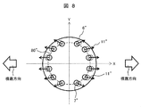
次に、図8及び図9を用いて、本発明との第2比較例のノズルプレート6''について説明する。図8は、本発明との第2比較例の燃料噴射弁におけるノズルプレート6''を弁体側から見た図である。図9は、本発明との第2比較例の燃料噴射弁の噴孔近傍の流れ場について説明した図である。なお、第1実施例及び第1比較例と同じ構成については同じ符号を付し、説明を省略する。
第2比較例では、2方向の噴霧を形成するために、噴孔7''の入口面から出口面に向かって、ノズルプレート6''の中心から離れる方向に噴孔7''を傾斜させていた。この場合、図9に示すように、主流方向18に対して噴孔7''の傾斜方向が最適ではなく、噴孔7''へ流れ込む燃料103cが噴孔壁面72aに衝突する力が弱いために、噴孔7''の中心軸73aに垂直な面内の流速が小さくなり、噴孔7''内では流れ103dのように噴孔傾斜に沿った流れとなる。すなわち燃料流れは、面内方向速度成分が小さくなり、軸方向速度成分が大きくなる。これにより噴孔7''内の周方向および半径方向の速度成分が小さいため、噴孔7''の下流で燃料の液膜9aは広がりにくく、液膜9aから分裂した液滴10aの粒径が悪化する課題があった。
したがって微粒化を促進するには、噴孔の傾斜はなるべく噴孔に流れ込む燃料の流れに対向するように傾斜させることが好ましい。しかし、噴孔に流れ込む流れに完全に対向する方向に傾斜させると、2方向噴霧を形成することが困難となる。一方、噴孔の傾斜方向を流れ込む燃料の流れと同方向、つまり、ノズルプレートの中心に対し外側へ噴孔を傾斜させると、2方向の噴霧を形成することは容易であるが、微粒化することは困難となる。
本実施例によるノズルプレート6では、第1グループ内における噴孔7a~7c間の最大の噴孔間距離及び第2グループ内における噴孔7e~7f間の最大の噴孔間距離のうち最大の噴孔間距離よりも、第1噴孔群と第2噴孔群との距離、つまり、噴孔7c(7c’)と7d(7d’)との間の距離を大きくして、噴孔7a~7f、7a’~7f’を配置している。さらに本実施例によるノズルプレート6では、噴孔7a~7f、7a’~7f’を、出口面が入口面に対してノズルプレート6の中心軸102を含む一つの平面に近づく方向に傾斜させている。なおこの平面は、中心軸102とX軸とを含む平面である。このような構成にすることで、2方向噴霧を実現し、さらに微粒化も促進することが可能となる。
噴孔の傾斜方向について具体的に説明する。図10は、本発明の第1実施例に係る燃料噴射弁1のノズルプレート6を弁体3側から見た場合の、噴孔7cの近傍を拡大した図である。
なお、噴孔7a、7bも、以下で説明する噴孔7cと同様の考え方となる。噴孔7d、7e、7fは、X軸を通り紙面に垂直な面(X軸を通りY軸に垂直な面)に対し、噴孔7a、7b、7cと面対称となる。
噴孔7cの入口面7ciの中心7cioを通りX軸に平行な軸をX’軸、噴孔7cの入口面7ciの中心7cioを通りY軸に平行な軸をY’軸とする。噴孔7cの入口面7ciの中心7cioを通り、X軸、Y軸の原点Oを中心とする円を配置円80とする。
本実施例において、噴孔7cの傾斜角を図10のθaの範囲に設定する。つまり、噴孔7cを、X’軸のX’>0の部分とY’軸のY’<0の部分とが成す角度範囲(X’>0かつY’<0の角度範囲)に向くように、傾斜させる。このとき、上記角度範囲には、X’軸上及びY’軸上は含まないこととする。
噴孔7cを上述のように傾斜させることで、噴孔7cの出口面の中心は、X’軸のX’>0の範囲で、かつY’軸のY’<0の範囲に位置する。これにより、2方向の噴霧を形成し、かつ、微粒化を促進することができる。この傾斜角の設定では、噴孔7cの出口面の中心位置の設定範囲に、X’軸上及びY’軸上は含まれない。
第1噴孔群7Aに配置された噴孔7a~7fから噴射される噴霧の総体的(全体的)な噴射方向を図3に投影すると、この噴射方向は図3のX軸に沿い正方向に向かう。また第2噴孔群7Bに配置された噴孔7a’~7f’から噴射される噴霧の総体的(全体的)な噴射方向を図3に投影すると、この噴射方向は図3のX軸に沿い負方向に向かう。従って、噴孔7cの出口面の中心位置の設定範囲からX’軸上を除くことで(すなわち噴孔7cの傾斜方向からX’軸上を除くことで)、噴孔7cを第1噴孔群7Aによって形成される第1燃料噴霧の噴射方向に対して大きく傾斜させることができる。これにより、噴孔7cの傾斜角度を、噴孔7cに流入する燃料の流れ方向に対して、より大きくすることができる。
一方、噴孔7cの出口面の中心位置の設定範囲にY’軸上を含める(すなわち噴孔7cの傾斜方向にY’軸上を含める)と、噴孔7cの噴射方向は、図3のY軸を通り、かつ図10の紙面に垂直な平面(Y軸を通りX軸に垂直な面)に平行な方向となる。このため、第1噴孔群7Aから噴射された噴霧と第1噴孔群7Bから噴射された噴霧とは平行に噴射されることになる。本実施例では、図4に示すように、噴射方向の前方(下流側)で第1燃料噴霧と第2燃料噴霧とが離れていくようにするために、噴孔7cの出口面の中心位置の設定範囲にY’軸上を含めない構成(すなわち噴孔7cの傾斜方向にY’軸上を含めない構成)とした。
しかし、例えば、第1噴孔群7Aに配置された噴孔7a~7fから噴射される噴霧の総体的(全体的)な噴射方向を、図3のY軸に平行で、且つY軸の正方向に向かう方向とし、
第2噴孔群7Bに配置された噴孔7a’~7f’から噴射される噴霧の総体的(全体的)な噴射方向を、図3のY軸に平行で、且つY軸の負方向に向かう方向とすることで、図4に示すのと同様な2方向噴霧を形成することができる。この場合は、噴孔7cの出口面の中心位置の設定範囲にY’軸上を含めることができる(すなわち噴孔7cの傾斜方向にY’軸上を含めることができる)。
第2噴孔群7Bに配置された噴孔7a’~7f’から噴射される噴霧の総体的(全体的)な噴射方向を、図3のY軸に平行で、且つY軸の負方向に向かう方向とすることで、図4に示すのと同様な2方向噴霧を形成することができる。この場合は、噴孔7cの出口面の中心位置の設定範囲にY’軸上を含めることができる(すなわち噴孔7cの傾斜方向にY’軸上を含めることができる)。
また、噴孔7cの傾斜角を、さらにθbの範囲に限定して設定するとよい。つまり、配置円80の噴孔中心位置における接線80aと、Y’軸のY’<0の部分とが成す角度範囲に向くように噴孔7cを傾斜させる。この角度範囲は、Y’<0となる範囲に構成される角度範囲である。このとき、噴孔7cの出口面の中心は、Y’<0となる範囲において、接線80aとY’軸のY’<0の部分とに挟まれた範囲に位置する。これにより、より一層微粒化を促進することができる。なお、この場合、噴孔7cは接線80aの線上に沿って傾斜させてもよい。このとき噴孔7cの出口面の中心は、接線80aの線上に配置されることになる。
接線80aとY’軸のY’<0の部分とが成す角度範囲θbは、X’>0となる範囲で、かつ配置円80の内側の範囲に、ほぼ一致する。従って、噴孔7cを、X’>0となる範囲で、かつ配置円80の内側の範囲に、傾斜させてもよい。この場合、噴孔7cの出口面の中心は、X’>0となる範囲で、かつ配置円80の内側の範囲に位置する。
また、第1グループ7A1の噴孔7cから噴射された噴霧と第2グループ7A2の噴孔7dから噴射された噴霧とが噴孔直下で互いに干渉すると、微粒化性能が悪化する恐れがある。図11は、図3のB―B断面における噴孔の傾斜角度と噴霧干渉距離の関係を模式的に示した図である。
本実施例では、第1グループ7A1の噴孔7a~7cと第2グループ7A2の噴孔7d~7fとの間で、相互の中心軸71が交差するように配置された噴孔の組み合わせができる。噴孔7cと噴孔7dとは、相互の中心軸71が交差するように配置された噴孔の組み合わせの中で、中心間距離Lが最も短い噴孔の組み合わせである。
B-B断面における噴孔7cの水平方向に対する傾きをα、噴孔7dの水平方向に対する傾きをβ、噴孔7cと噴孔7dとの中心間距離をL、噴孔7cの中心軸7caと噴孔7dの中心軸7daとが交わる点をQ、噴孔7cの入口面7ciの中心7cioと噴孔7dの入口面7diの中心7dioとを結ぶ直線(線分)150と点Qとの高さ方向の距離(直線150に下した垂線の長さ)をXとすると、Xは式(1)で表される。

このとき、Xが2mm以上となるようにα、βを設定すると、噴霧干渉の影響を抑制でき微粒化が促進される。さらに、Xが5mm以上だとより好ましく、さらにXが7mm以上であればさらに好ましい。
特許文献1の燃料噴射弁の構成を本実施例に適用した場合、配置円80の円周上で第1噴孔群7Aの端部に位置する噴孔7a(7f)と配置円80の円周上で第2噴孔群の端部に位置する噴孔7a’(7f’)との間隔(入口面の中心間距離)が、第1噴孔群7A内における噴孔7a~7fの間隔(入口面の中心間距離)及び第2噴孔群7B内における噴孔7a’~7f’の間隔(入口面の中心間距離)よりも大きくなる。
一方、本実施例では、第1噴孔群7Aの中で最小となるグループ間噴孔間距離L及び第2噴孔群7Bの中で最小となるグループ間噴孔間距離Lは、第1噴孔群7Aを構成する複数の噴孔7a~7fと第2噴孔群7Bを構成する複数の噴孔7a’~7f’との間で最も近接した2つの噴孔7a(7f)と7a’(7f’)の各入口面の中心間距離よりも大きくなるように、各噴孔7の入口面の中心間距離を設定している。
すなわち、本実施例では、入口面の中心間距離(L)が大きく設定される2つの噴孔が同一の噴孔群内に存在する。これは、上述したように、同一の噴孔群内の噴孔の中心軸が噴射方向の前方で接近するように傾斜していることに起因しており、噴孔に近接した位置で複数の噴霧が衝突するのを避けるためである。
本実施例の燃料噴射弁1においても、配置円80の円周上で第1噴孔群7Aの端部に位置する噴孔7aの入口面と配置円80の円周上で第2噴孔群7Bの端部に位置する噴孔7a’の入口面との中心間距離を、他の噴孔の入口面の中心間距離lよりも大きくしてもよい。また、配置円80の円周上で第1噴孔群7Aの端部に位置する噴孔7fの入口面と配置円80の円周上で第2噴孔群7Bの端部に位置する噴孔7f’の入口面との中心間距離を、他の噴孔の入口面の中心間距離lよりも大きくしてもよい。
しかし、噴孔7c、7c’の入口面と噴孔7d、7d’の入口面との中心間距離Lを大きくするために、配置円80の円周上では噴孔7を配置するスペースが限られている。そのため、噴孔7aの入口面と噴孔7a’の入口面との中心間距離及び噴孔7fの入口面と噴孔7f’の入口面との中心間距離は、中心間距離Lよりも小さくすることが好ましい。
次に、図12を用いて、本発明に係る第2実施例を説明する。図12は、本発明の第2実施例に係る燃料噴射弁1のノズルプレート6を弁体3側から見た図である。なお、第1実施例と同じ構成については同じ符号を付し、説明を省略する。
第1実施例との違いは、噴孔7c、7c’がX軸上に配置されており、噴孔7c、7c’の傾斜方向がノズルプレート6中心に対し半径方向外側に向いている点である。この場合、噴孔7aと噴孔7bとの間隔(噴孔7aの入口面と噴孔7bの入口面との中心間距離)lよりも、噴孔7bと噴孔7dとの間隔(噴孔7bの入口面と噴孔7dの入口面との中心間距離)Lの方が大きくなるように噴孔は配置される。
噴孔7a’、7b’、7c’、7d’、7e’は、噴孔7a、7b、7c、7d、7eを、Y軸を通り図12の紙面に垂直な面(Y軸及び中心軸線1aを含む面、或いはY軸を通りX軸に垂直な面)に対して面対称となっている。また、噴孔7d、7eは、X軸を通る紙面に垂直な面(X軸及び中心軸線1aを含む面、或いはX軸を通りY軸に垂直な面)に対し、噴孔7a、7bと面対称となる。
本実施例の場合、噴孔7cの中心軸(噴射方向)は、第1噴孔群7Aの中で、X座標値が最も大きい。また、噴孔7cの中心軸(噴射方向)は、X軸を通り、かつY軸に垂直な平面上に存在するため、第1噴孔群7Aの他の噴孔7a、7b、7d、7eの中心軸と交差することがない。第2噴孔群7Bの噴孔7c’も第1噴孔群7Aの噴孔7cと同様に、その中心軸(噴射方向)は、第2噴孔群7Bの他の噴孔7a’、7b’、7d’、7e’の中心軸と交差することがない。従って、噴孔7c及び噴孔7c’は、他の噴孔との距離を特別に考慮する必要がない。
第1噴孔群7Aの噴孔7cの中心軸(噴射方向)は、第1噴孔群7Aの他の噴孔7a、7b、7d、7eの中心軸と交差するようにしてもよい。ただしこの場合は、噴孔7cの中心軸と他の噴孔7a、7b、7d、7eの中心軸とが交差する位置が各噴孔の出口からある程度離れるように、噴孔間距離又は噴孔の傾斜角度に配慮する必要がある。また、第2噴孔群7Bの噴孔7c’の中心軸(噴射方向)は、第2噴孔群7Bの他の噴孔7a’、7b’、7d’、7e’の中心軸と交差するようにしてもよい。ただしこの場合は、噴孔7c’の中心軸と他の噴孔7a’、7b’、7d’、7e’の中心軸とが交差する位置が各噴孔の出口からある程度離れるように、噴孔間距離又は噴孔の傾斜角度に配慮する必要がある。
噴孔7a、7b、7d、7e及び噴孔7a’、7b’、7d’、7e’は、Y軸を通りX軸に垂直な面に対して面対称に配置された噴孔である。このようにX軸を挟んで配置された噴孔に対して、入口面の中心間距離を上述のように設定する必要がある。
本実施例のような構造にすると、噴孔7c、7c’は2方向噴霧を容易に形成することができ、かつ、噴孔7a、7b、7d、7e、7a’、7b’、7d’、7e’は第1の実施例と同様、微粒化を促進することができる。つまり、噴孔7c、7c’は2方向噴霧の形成、噴孔7a、7b、7d、7e、7a’、7b’、7d’、7e’は微粒化の促進といったように、担う役割を分担させることができる。このようにすることで、噴霧角の制御が容易になるといった効果がある。
図13を用いて本発明による第3実施例を説明する。図13は、本発明の第3実施例に係る燃料噴射弁1の弁体3の先端部3bの近傍を拡大した断面図である。なお、第1実施例及び第2実施例と同じ構成については同じ符号を付し、説明を省略する。
第1実施例では、ノズルプレート6の形状は下凸形状6aとして説明した。本実施例ではノズルプレート6の中央付近(中心軸102の近傍で開口部5cと対向する部分)は下凸形状6aとなっており、噴孔7が加工される部分は平面構造となっている。その他の構成は第1実施例又は第2実施例と同様な構成とする。
このような構造にすると、弁座面5bと弁体3の先端部3bとの間を通過した燃料は開口部5cを通り、矢印17の方向からノズルプレート6の上面に衝突する。その後、矢印18のようにノズルプレート6の中央からノズルプレート表面に沿って半径方向外側に流れる。この際、ノズルプレート6の中央付近は下凸形状6aとなっているため、ノズルプレート表面付近の燃料の速度が大きくなる。そして、噴孔7を通過後、液膜9を形成し、表面張力波による不安定性や空気との剪断力により液滴10へと分裂して、燃料の微粒化が達成される。
このように、下凸形状6aを設けることでノズルプレート6表面近傍の速度を大きくでき、微粒化を促進することができる。そして、噴孔7の設置部分を平面構造とすることで、噴孔7の加工精度が向上し、燃料を噴霧させる方向の制御が容易になると共に、ノズルプレート6とシール部材5aとの間隔を小さくすることができ、ノズルプレート6と弁座面5bと弁体3とで囲まれる空間の体積を小さくすることができる。この体積を小さくすることで、目的とする量の燃料を正確に噴霧することが可能となる。
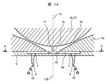
図14を用いて本発明による第4実施例を説明する。図14は、本発明の第4実施例に係る燃料噴射弁1の弁体3の先端部3bの近傍を拡大した断面図である。なお、第1~第3実施例と同じ構成については同じ符号を付し、説明を省略する。
本実施例では、図14のように、ノズルプレート6の中心軸102の近傍で開口部5cと対向する部分を平面で構成した。すなわち、ノズルプレート6は全体が平面で構成され、下凸形状6aが形成されていない。本実施例では、下凸形状6aの代わりに、中心軸102の近傍で開口部5cと対向する部分から径方向外側(外径側)に向けて広がる凹部6bを形成している。そして、凹部6bの底面に、入口面が開口する噴孔7を設けている。
その他の構成は第1~第3実施例と同様な構成とする。
その他の構成は第1~第3実施例と同様な構成とする。
この場合、燃料を噴霧させる方向の制御が容易となるとともに、加工は非常に容易となる。
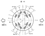
図15を用いて本発明による第4の実施例を説明する。図15は、本発明の第5実施例に係る燃料噴射弁1のノズルプレート6を弁体3側から見た図である。なお、第1~第3実施例と同じ構成については同じ符号を付し、説明を省略する。
実施例1では、全ての噴孔7が同じ配置円上に配置されている構成を説明した。本実施例では、複数の配置円80、81上に噴孔7が配置されている構成となっている。
第1噴孔群7Aの第1グループ7A1として、噴孔7a、7b、7cが設けられている。第1噴孔群7Aの第2グループ7A2として、噴孔7d、7e、7fが設けられている。第2噴孔群7Bの第1グループ7B1として、噴孔7a’、7b’、7c’が設けられている。第2噴孔群7Bの第2グループ7B2として、噴孔7d’、7e’、7f’が設けられている。
この場合、噴孔群内におけるグループ間の距離は、噴孔7b、7b’と噴孔7e、7e’との距離Lとなり、各噴孔群において各グループを構成する噴孔7a~7c、7d~7f、7a’~7c ’、7d’~7f’の噴孔間最大距離(各噴孔入口面の中心間距離)よりもLが大きくなるように、噴孔7が配置される。
このような構成にすることで、実施例1と同等の効果が得られ、噴霧角の制御も容易となる。
また、グループ間の距離Lを大きくすることにより、一つの配置円80上における噴孔の配置スペースは小さくなる。このため、複数の噴孔7を複数の配置円80,81に分散して配置することにより、多数の噴孔を配置することができる。或いは、狭いスペースに多数の噴孔が密集することを防げるので、ノズルプレート6の強度を低下させずに済む。
本実施例でも、噴孔7の傾斜方向について、図10で説明した角度範囲θa及びθbを適用するとよい。また、第2実施例の噴孔7c、7c’や、第3及び第4実施例のノズルプレート6を適用してもよい。
なお、本発明は上記した各実施例に限定されるものではなく、様々な変形例が含まれる。例えば、上記した実施例は本発明を分かりやすく説明するために詳細に説明したものであり、必ずしも全ての構成を備えるものに限定されるものではない。また、ある実施例の構成の一部を他の実施例の構成に置き換えることが可能であり、また、ある実施例の構成に他の実施例の構成を加えることも可能である。また、各実施例の構成の一部について、他の構成の追加・削除・置換をすることが可能である。
1…燃料噴射弁、1a…燃料噴射弁の中心軸線、2…ケーシング、2a…燃料供給口、3…弁体、4…アンカー、5…ノズル体、5b…弁座面、5c…開口部、6…ノズルプレート、6a…下凸形状、7、7a、7b、7c、7d、7e、7f、7a’、7b’、7c’、7d’、7e’ …噴孔、11…噴射孔の傾斜方向、12…スプリング、13…スプリングアジャスタ、14…電磁コイル、15…コア、16…ヨーク、17…弁部材よりも下流側に配置された燃料通路部の開口部での燃料流れ、18…ノズルプレート上での主流となる燃料流れ、72、72a・・・噴孔内における燃料流れの衝突面、71、73、73a…噴孔の中心軸、80、81…配置円、102・・・ノズルプレートの中心軸、103a、103b、103c、103d・・・噴孔近傍及び噴孔内の流れ。
Claims (7)
- 中心軸線方向に変位可能に構成された弁体と、前記弁体と協働して燃料通路を開閉する弁座と、前記弁座よりも下流側に設けられ前記燃料通路を通過した燃料を外部に噴射する複数の噴孔と、を備え、前記複数の噴孔の少なくとも一部の複数の噴孔によって構成される第1噴孔群の前記複数の噴孔から噴射される燃料が第1の噴射方向を指向する第1燃料噴霧を形成する燃料噴射弁において、
前記中心軸線方向に対して直交する仮想平面に、前記第1噴孔群を構成する前記複数の噴孔と前記第1燃料噴霧が指向する前記第1の噴射方向とを投影すると共に、前記第1の噴射方向に沿う仮想X軸と前記仮想X軸に直交する仮想Y軸とを有し、原点が前記中心軸線を前記仮想平面に投影した投影中心点に一致する仮想直交座標系を前記仮想平面に仮想した場合に、
前記仮想平面において、前記第1噴孔群を構成する前記複数の噴孔は、前記噴孔の入口面から出口面に向かう噴孔中心軸が、前記仮想直交座標系の前記原点と前記入口面の中心とを結ぶ直線とは異なる方向に向かって形成されると共に、前記入口面の中心に対して前記出口面の中心が前記仮想X軸に近接した位置に形成されることを特徴とする燃料噴射弁。 - 請求項1に記載の燃料噴射弁において、
前記第1噴孔群を構成する前記複数の噴孔は、前記仮想X軸を境界として、第1グループを構成する複数の噴孔と第2グループを構成する複数の噴孔とに分けられ、
前記第1グループを構成する前記複数の噴孔と前記第2グループを構成する前記複数の噴孔との間で各噴孔の入口面の中心間に構成されるグループ間噴孔間距離の中で最小となるグループ間噴孔間距離が、前記第1グループを構成する前記複数の噴孔の間で各噴孔の入口面の中心間に構成されるグループ内噴孔間距離、及び前記第2グループを構成する前記複数の噴孔の間で各噴孔の入口面の中心間に構成されるグループ内噴孔間距離の中で最大となるグループ内噴孔間距離よりも大きく設定されていることを特徴とする燃料噴射弁。 - 請求項2に記載の燃料噴射弁において、
前記第1の噴射方向とは異なる第2の噴射方向を指向する第2燃料噴霧を形成する第2噴孔群を備え、
前記第2噴孔群は、前記仮想X軸を境界として、第3グループを構成する複数の噴孔と第4グループを構成する複数の噴孔とに分けられる複数の噴孔を有し、
前記仮想直交座標系の第一象限に前記第1グループを構成する前記複数の噴孔が配置され、
前記仮想直交座標系の第二象限に前記第3グループを構成する前記複数の噴孔が配置され、
前記仮想直交座標系の第三象限に前記第4グループを構成する前記複数の噴孔が配置され、
前記仮想直交座標系の第四象限に前記第2グループを構成する前記複数の噴孔が配置され、
前記第3グループを構成する前記複数の噴孔と前記第4グループを構成する前記複数の噴孔との間で各噴孔の入口面の中心間に構成されるグループ間噴孔間距離の中で最小となるグループ間噴孔間距離が、前記第3グループを構成する前記複数の噴孔の間で各噴孔の入口面の中心間に構成されるグループ内噴孔間距離、及び前記第4グループを構成する前記複数の噴孔の間で各噴孔の入口面の中心間に構成されるグループ内噴孔間距離の中で最大となるグループ内噴孔間距離よりも大きく設定されていることを特徴とする燃料噴射弁。 - 請求項3に記載の燃料噴射弁において、
前記第3グループを構成する前記複数の噴孔及び前記第4グループを構成する前記複数の噴孔は、前記仮想Y軸を通り前記仮想X軸に垂直な平面に対して、前記第1グループを構成する前記複数の噴孔及び前記第2グループを構成する前記複数の噴孔と面対称に配置されていることを特徴とする燃料噴射弁。 - 請求項3に記載の燃料噴射弁において、
前記第1噴孔群の前記複数の噴孔及び前記第2噴孔群の前記複数の噴孔は、入口面の中心が前記原点を中心とする配置円の円周上に位置するように配置され、
前記複数の噴孔のうち少なくとも一つは、前記配置円の円周よりも内側の範囲に出口面の中心が位置するように傾斜していることを特徴とする燃料噴射弁。 - 請求項3に記載の燃料噴射弁において、
前記第1噴孔群の前記複数の噴孔及び前記第2噴孔群の前記複数の噴孔は、複数の配置円の円周上に配置されたことを特徴とする燃料噴射弁。 - 請求項4に記載の燃料噴射弁において、
前記第1噴孔群の中で最小となる前記グループ間噴孔間距離及び前記第2噴孔群の中で最小となる前記グループ間噴孔間距離は、前記第1噴孔群を構成する前記複数の噴孔と前記第2噴孔群を構成する前記複数の噴孔との間で最も近接した2つの噴孔の各入口面の中心間距離よりも大きいことを特徴とする燃料噴射弁。
Priority Applications (2)
| Application Number | Priority Date | Filing Date | Title |
|---|---|---|---|
| CN201680067564.4A CN108235716A (zh) | 2015-11-26 | 2016-09-21 | 燃料喷射阀 |
| US15/779,402 US20180306155A1 (en) | 2015-11-26 | 2016-09-21 | Fuel Injection Valve |
Applications Claiming Priority (2)
| Application Number | Priority Date | Filing Date | Title |
|---|---|---|---|
| JP2015-230559 | 2015-11-26 | ||
| JP2015230559A JP6654875B2 (ja) | 2015-11-26 | 2015-11-26 | 燃料噴射弁 |
Publications (1)
| Publication Number | Publication Date |
|---|---|
| WO2017090308A1 true WO2017090308A1 (ja) | 2017-06-01 |
Family
ID=58763397
Family Applications (1)
| Application Number | Title | Priority Date | Filing Date |
|---|---|---|---|
| PCT/JP2016/077839 Ceased WO2017090308A1 (ja) | 2015-11-26 | 2016-09-21 | 燃料噴射弁 |
Country Status (4)
| Country | Link |
|---|---|
| US (1) | US20180306155A1 (ja) |
| JP (1) | JP6654875B2 (ja) |
| CN (1) | CN108235716A (ja) |
| WO (1) | WO2017090308A1 (ja) |
Cited By (1)
| Publication number | Priority date | Publication date | Assignee | Title |
|---|---|---|---|---|
| WO2020013065A1 (ja) * | 2018-07-13 | 2020-01-16 | 日立オートモティブシステムズ株式会社 | 燃料噴射弁 |
Citations (11)
| Publication number | Priority date | Publication date | Assignee | Title |
|---|---|---|---|---|
| JP2002130082A (ja) * | 2000-10-24 | 2002-05-09 | Keihin Corp | 燃料噴射弁 |
| JP2004052751A (ja) * | 2002-05-30 | 2004-02-19 | Hitachi Unisia Automotive Ltd | 燃料噴射弁 |
| JP2005042615A (ja) * | 2003-07-22 | 2005-02-17 | Denso Corp | 流体噴射弁 |
| JP2005307781A (ja) * | 2004-04-19 | 2005-11-04 | Mitsubishi Electric Corp | 燃料噴射弁 |
| JP2007182807A (ja) * | 2006-01-06 | 2007-07-19 | Hitachi Ltd | 燃料噴射弁 |
| JP2008101555A (ja) * | 2006-10-19 | 2008-05-01 | Hitachi Ltd | 燃料噴射弁およびそれを搭載した内燃機関 |
| JP2008121531A (ja) * | 2006-11-10 | 2008-05-29 | Denso Corp | 流体噴射装置 |
| JP2009228467A (ja) * | 2008-03-19 | 2009-10-08 | Hitachi Ltd | 燃料噴射弁 |
| JP2010249125A (ja) * | 2009-03-23 | 2010-11-04 | Denso Corp | 燃料噴射弁 |
| WO2014024292A1 (ja) * | 2012-08-09 | 2014-02-13 | 三菱電機株式会社 | 燃料噴射弁 |
| WO2016143166A1 (ja) * | 2015-03-11 | 2016-09-15 | 日立オートモティブシステムズ株式会社 | 燃料噴射弁 |
Family Cites Families (7)
| Publication number | Priority date | Publication date | Assignee | Title |
|---|---|---|---|---|
| JPH07127550A (ja) * | 1993-11-05 | 1995-05-16 | Nippondenso Co Ltd | 燃料噴射弁の噴流調整板及びその製造方法 |
| JP3164023B2 (ja) * | 1997-06-25 | 2001-05-08 | トヨタ自動車株式会社 | 内燃機関の燃料噴射弁 |
| EP1816344B1 (en) * | 2006-02-03 | 2009-07-08 | Continental Automotive GmbH | Valve assembly for an injection valve and injection valve |
| JP4218696B2 (ja) * | 2006-05-19 | 2009-02-04 | トヨタ自動車株式会社 | 燃料噴射ノズル |
| JP4305962B2 (ja) * | 2007-01-12 | 2009-07-29 | 株式会社デンソー | 噴孔部材およびそれを用いた燃料噴射弁 |
| JP5395007B2 (ja) * | 2010-07-22 | 2014-01-22 | 日立オートモティブシステムズ株式会社 | 燃料噴射弁およびそれを搭載した車両用内燃機関 |
| DE102010031653A1 (de) * | 2010-07-22 | 2012-01-26 | Robert Bosch Gmbh | Einspritzvorrichtung mit verbesserter Spray-Aufbereitung |
-
2015
- 2015-11-26 JP JP2015230559A patent/JP6654875B2/ja not_active Expired - Fee Related
-
2016
- 2016-09-21 WO PCT/JP2016/077839 patent/WO2017090308A1/ja not_active Ceased
- 2016-09-21 CN CN201680067564.4A patent/CN108235716A/zh active Pending
- 2016-09-21 US US15/779,402 patent/US20180306155A1/en not_active Abandoned
Patent Citations (11)
| Publication number | Priority date | Publication date | Assignee | Title |
|---|---|---|---|---|
| JP2002130082A (ja) * | 2000-10-24 | 2002-05-09 | Keihin Corp | 燃料噴射弁 |
| JP2004052751A (ja) * | 2002-05-30 | 2004-02-19 | Hitachi Unisia Automotive Ltd | 燃料噴射弁 |
| JP2005042615A (ja) * | 2003-07-22 | 2005-02-17 | Denso Corp | 流体噴射弁 |
| JP2005307781A (ja) * | 2004-04-19 | 2005-11-04 | Mitsubishi Electric Corp | 燃料噴射弁 |
| JP2007182807A (ja) * | 2006-01-06 | 2007-07-19 | Hitachi Ltd | 燃料噴射弁 |
| JP2008101555A (ja) * | 2006-10-19 | 2008-05-01 | Hitachi Ltd | 燃料噴射弁およびそれを搭載した内燃機関 |
| JP2008121531A (ja) * | 2006-11-10 | 2008-05-29 | Denso Corp | 流体噴射装置 |
| JP2009228467A (ja) * | 2008-03-19 | 2009-10-08 | Hitachi Ltd | 燃料噴射弁 |
| JP2010249125A (ja) * | 2009-03-23 | 2010-11-04 | Denso Corp | 燃料噴射弁 |
| WO2014024292A1 (ja) * | 2012-08-09 | 2014-02-13 | 三菱電機株式会社 | 燃料噴射弁 |
| WO2016143166A1 (ja) * | 2015-03-11 | 2016-09-15 | 日立オートモティブシステムズ株式会社 | 燃料噴射弁 |
Cited By (3)
| Publication number | Priority date | Publication date | Assignee | Title |
|---|---|---|---|---|
| WO2020013065A1 (ja) * | 2018-07-13 | 2020-01-16 | 日立オートモティブシステムズ株式会社 | 燃料噴射弁 |
| JP2020012377A (ja) * | 2018-07-13 | 2020-01-23 | 日立オートモティブシステムズ株式会社 | 燃料噴射弁 |
| JP7032256B2 (ja) | 2018-07-13 | 2022-03-08 | 日立Astemo株式会社 | 燃料噴射弁 |
Also Published As
| Publication number | Publication date |
|---|---|
| JP2017096199A (ja) | 2017-06-01 |
| US20180306155A1 (en) | 2018-10-25 |
| CN108235716A (zh) | 2018-06-29 |
| JP6654875B2 (ja) | 2020-02-26 |
Similar Documents
| Publication | Publication Date | Title |
|---|---|---|
| JP5933720B2 (ja) | 燃料噴射弁 | |
| KR101019324B1 (ko) | 연료 분사 밸브 | |
| JP2009197682A (ja) | 燃料噴射弁 | |
| US20130256428A1 (en) | Fuel Injection Valve | |
| JP6808356B2 (ja) | 燃料噴射弁 | |
| JP6392689B2 (ja) | 燃料噴射弁 | |
| JP2011506849A (ja) | 燃料噴射弁 | |
| JP6121870B2 (ja) | 燃料噴射装置の微粒化技術 | |
| JP2017096199A (ja) | 燃料噴射弁 | |
| CN109983219B (zh) | 燃料喷射阀 | |
| JP5320116B2 (ja) | 燃料噴射弁 | |
| JP6523984B2 (ja) | 燃料噴射弁 | |
| JP4555955B2 (ja) | 燃料噴射弁およびそれを搭載した内燃機関 | |
| JP5258644B2 (ja) | 燃料噴射弁 | |
| WO2016076007A1 (ja) | 燃料噴射弁 | |
| US20200030823A1 (en) | Multi-dimple orifice disc for a fluid injector, and methods for constructing and utilizing same | |
| JP2016211389A (ja) | 燃料噴射弁 | |
| JP5631442B1 (ja) | 燃料噴射弁 | |
| JP2007182807A (ja) | 燃料噴射弁 | |
| JP2015135062A (ja) | 燃料噴射弁 | |
| JP2007224794A (ja) | 燃料噴射装置 |
Legal Events
| Date | Code | Title | Description |
|---|---|---|---|
| 121 | Ep: the epo has been informed by wipo that ep was designated in this application |
Ref document number: 16868257 Country of ref document: EP Kind code of ref document: A1 |
|
| WWE | Wipo information: entry into national phase |
Ref document number: 15779402 Country of ref document: US |
|
| NENP | Non-entry into the national phase |
Ref country code: DE |
|
| 122 | Ep: pct application non-entry in european phase |
Ref document number: 16868257 Country of ref document: EP Kind code of ref document: A1 |