WO2017082151A1 - リヤサブフレーム構造 - Google Patents
リヤサブフレーム構造 Download PDFInfo
- Publication number
- WO2017082151A1 WO2017082151A1 PCT/JP2016/082707 JP2016082707W WO2017082151A1 WO 2017082151 A1 WO2017082151 A1 WO 2017082151A1 JP 2016082707 W JP2016082707 W JP 2016082707W WO 2017082151 A1 WO2017082151 A1 WO 2017082151A1
- Authority
- WO
- WIPO (PCT)
- Prior art keywords
- width direction
- cross member
- vehicle width
- vehicle
- front cross
- Prior art date
- Legal status (The legal status is an assumption and is not a legal conclusion. Google has not performed a legal analysis and makes no representation as to the accuracy of the status listed.)
- Ceased
Links
Images






Classifications
-
- B—PERFORMING OPERATIONS; TRANSPORTING
- B62—LAND VEHICLES FOR TRAVELLING OTHERWISE THAN ON RAILS
- B62D—MOTOR VEHICLES; TRAILERS
- B62D25/00—Superstructure or monocoque structure sub-units; Parts or details thereof not otherwise provided for
- B62D25/20—Floors or bottom sub-units
- B62D25/2009—Floors or bottom sub-units in connection with other superstructure subunits
- B62D25/2027—Floors or bottom sub-units in connection with other superstructure subunits the subunits being rear structures
-
- B—PERFORMING OPERATIONS; TRANSPORTING
- B62—LAND VEHICLES FOR TRAVELLING OTHERWISE THAN ON RAILS
- B62D—MOTOR VEHICLES; TRAILERS
- B62D21/00—Understructures, i.e. chassis frame on which a vehicle body may be mounted
- B62D21/11—Understructures, i.e. chassis frame on which a vehicle body may be mounted with resilient means for suspension, e.g. of wheels or engine; sub-frames for mounting engine or suspensions
-
- B—PERFORMING OPERATIONS; TRANSPORTING
- B62—LAND VEHICLES FOR TRAVELLING OTHERWISE THAN ON RAILS
- B62D—MOTOR VEHICLES; TRAILERS
- B62D21/00—Understructures, i.e. chassis frame on which a vehicle body may be mounted
-
- B—PERFORMING OPERATIONS; TRANSPORTING
- B62—LAND VEHICLES FOR TRAVELLING OTHERWISE THAN ON RAILS
- B62D—MOTOR VEHICLES; TRAILERS
- B62D21/00—Understructures, i.e. chassis frame on which a vehicle body may be mounted
- B62D21/02—Understructures, i.e. chassis frame on which a vehicle body may be mounted comprising longitudinally or transversely arranged frame members
-
- B—PERFORMING OPERATIONS; TRANSPORTING
- B62—LAND VEHICLES FOR TRAVELLING OTHERWISE THAN ON RAILS
- B62D—MOTOR VEHICLES; TRAILERS
- B62D21/00—Understructures, i.e. chassis frame on which a vehicle body may be mounted
- B62D21/02—Understructures, i.e. chassis frame on which a vehicle body may be mounted comprising longitudinally or transversely arranged frame members
- B62D21/03—Understructures, i.e. chassis frame on which a vehicle body may be mounted comprising longitudinally or transversely arranged frame members transverse members providing body support
-
- B—PERFORMING OPERATIONS; TRANSPORTING
- B62—LAND VEHICLES FOR TRAVELLING OTHERWISE THAN ON RAILS
- B62D—MOTOR VEHICLES; TRAILERS
- B62D25/00—Superstructure or monocoque structure sub-units; Parts or details thereof not otherwise provided for
- B62D25/08—Front or rear portions
-
- B—PERFORMING OPERATIONS; TRANSPORTING
- B62—LAND VEHICLES FOR TRAVELLING OTHERWISE THAN ON RAILS
- B62D—MOTOR VEHICLES; TRAILERS
- B62D25/00—Superstructure or monocoque structure sub-units; Parts or details thereof not otherwise provided for
- B62D25/20—Floors or bottom sub-units
Definitions
- the present invention relates to a rear subframe structure for a vehicle, and more specifically, a rear subframe including a front cross member extending in the vehicle width direction and a pair of left and right side members connected to the front cross member and extending in the vehicle front-rear direction. And a rear subframe structure in which vehicle body attachment portions are provided at both ends of the front cross member in the vehicle width direction.
- the rear sub-frame is configured by connecting a pair of front and rear cross members extending in the vehicle width direction and left and right side members extending in the vehicle front-rear direction in a substantially cross-beam shape in a vehicle plan view.
- the front vehicle body mounting portion of the rear subframe is located above In addition to being restricted by the rear seat pan, it is necessary to dispose the propeller shaft and the exhaust pipe in the vehicle front-rear direction, so the front cross member constituting the rear subframe may be formed in a bowl shape.
- Patent Document 1 an upper member element corresponding to a rear sub-frame is provided, and a hook-shaped portion through which a propeller shaft is inserted in the vehicle front-rear direction is formed in the upper member element, and a brace is formed below the hook-shaped member.
- the lower member element is provided.
- An object of the present invention is to provide a rear subframe structure capable of securing a path and reinforcing a front cross member.
- the present invention further includes a rear subframe including a front cross member extending in the vehicle width direction and a pair of left and right side members connected to the front cross member and extending in the vehicle front-rear direction.
- a rear sub-frame structure in which vehicle body mounting portions are provided at both ends in the width direction, a tunnel portion provided in the lower center of the front cross member so as to allow the propeller shaft to pass therethrough, and a vehicle width direction below the tunnel portion in the vehicle width direction
- a brace having tunnel portion attachment portions at both left and right ends, the brace having a central lower bulging portion that bulges downward avoiding the propeller shaft, and a vehicle width of the central lower bulging portion
- An upper bulging portion that is continuously provided on the outer side in the direction and bulges upward while avoiding the exhaust pipe.
- Inflection point is one that substantially positioned on the virtual line that connects linearly the tunnel section attachment portion of the left and right in the vehicle width direction.
- FIG. 3 is a cross-sectional view taken along line AA in FIG. 2.
- FIG. 3 is a cross-sectional view taken along line BB in FIG. 2.
- FIG. 3 is a cross-sectional view taken along line CC in FIG. 2. It is a principal part side view of FIG. FIG.
- FIG. 11 is a sectional view taken along line DD in FIG. 10. It is a top view of a partition member. It is a perspective view of a partition member. It is a perspective view of a stabilizer support member. It is a front view of a brace.
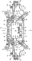
- FIG. 1 is a perspective view of the rear subframe structure
- FIG. 2 is a plan view of the rear subframe structure
- FIG. 3 is a bottom view of the rear subframe structure
- FIG. 4 is a front view of the rear subframe structure
- FIG. It is a rear view of a structure.
- arrow F indicates the front of the vehicle
- arrow R indicates the rear of the vehicle
- arrow IN indicates the inner side in the vehicle width direction
- arrow OUT indicates the outer side in the vehicle width direction (also in other drawings) The same).
- a rear sub-frame 10 that supports a rear suspension includes a front cross member 11 that extends in the vehicle width direction on the front side, a rear cross member 12 that extends in the vehicle width direction behind the front cross member 11,
- the front cross member 11 and the rear cross member 12 include a pair of upper side members 13 and 13 and a pair of lower side members 14 and 14 for connecting the front cross member 11 and the rear cross member 12 in the vehicle front-rear direction. It is connected in a shape.
- each of the members 11 to 14 described above has a closed cross-sectional structure.
- the upper side member 13 is connected to the vehicle width direction side portion of the front cross member 11 via a columnar portion 33 (see FIG. 10) described later, and extends from the connection portion to the rear of the vehicle. Yes.
- the rear cross member 12 connects the rear portions of the pair of left and right upper side members 13 and 13 and the rear portions of the pair of left and right lower side members 14 and 14 in the vehicle width direction, and connects the upper and lower side members 13 and 14 together. It is connected vertically.
- the lower side member 14 is located on the inner side in the vehicle width direction with respect to the upper side member 13, and connects the lower portion of the front cross member 11 and the lower portion of the rear cross member 12 in the vehicle front-rear direction. Yes.
- the interval between the rear end portions of the pair of left and right lower side members 14, 14 is formed narrower than the interval between the front end portions of the side members 14, 14. Accordingly, lower arm rear side support portions 12b and 12c (see FIG. 6), which will be described later, are provided at positions that overlap the upper side member 13 in plan view.
- front vehicle body mounting portions 15 are provided at both ends of the front cross member 11 in the vehicle width direction.
- the rear portion of the upper side member 13 is smoothly curved rearward and outward in the vehicle width direction, and rear vehicle body mounting portions 16 are provided at the rear end.
- the rear subframe 10 is attached to the vehicle body, specifically the rear side frame, through the vehicle body attachment portions 15 and 16.
- Numeral 17 is a lower arm.
- a link support portion 17a is provided at the front end of the lower arm 17 in the vehicle width direction, and the lower end portion of the integral link 18 is pivotally supported by the link support portion 17a. The portion is pivotally connected to the integral link support portion of the hub support 19.
- the integral link 18 is a link for controlling a recession angle (an angle formed between a swinging locus in a side view in which the rear wheel moves up and down and the road surface when the rear wheel rides on a step) and a road surface.
- an H-type lower arm is adopted as the lower arm 17.
- a connecting portion 17b is provided at the rear end of the lower arm 17 in the vehicle width direction (see FIG. 3), and the connecting portion 17b is pivotally connected to the lower arm support portion of the hub support 19.
- Numeral 20 is a toe control link for setting the rear wheel to toe-in and ensuring its straightness.
- a connecting portion 20 a is provided at an outer end portion of the toe control link 20 in the vehicle width direction, and the connecting portion 20 a is pivotally connected to a toe control link support portion of the hub support 19.
- Numeral 21 is an upper arm.
- a connecting portion 21 a is provided at the outer end in the vehicle width direction of the upper arm 21, and the connecting portion 20 a is pivotally connected to the upper arm support portion of the hub support 19.
- an I-type upper arm is employed as the upper arm 21.
- the hub support 19 is integrally formed with a damper support portion 19a extending inward in the vehicle width direction, and a damper 22 having a strut structure is attached to the damper support portion 19a.
- a bulging portion 17 c bulging rearward is provided at the rear portion of the lower arm 17.
- a coil spring 24 is stretched between a spring lower retainer 23 attached to the upper portion of the bulging portion 17c and a spring applicator (not shown) provided on a rear side frame on the vehicle body side.
- a stabilizer 25 is provided behind the rear cross member 12 along the rear cross member 12.
- the stabilizer 25 is bent toward the front of the vehicle so that both left and right end portions are positioned above the lower arm 17, and the bent end portion is connected to the lower arm 17 using a connecting member.
- This stabilizer 25 suppresses a roll angle at the time of a bump of only one wheel or rebound by resistance of torsional rigidity.
- a tunnel portion 11 a through which the propeller shaft 26 is inserted in the vehicle front-rear direction is provided at the lower center of the front cross member 11.
- the front cross member 11 is formed in a bowl shape.
- the brace 27 as a reinforcement member which connects the lower part of this tunnel part 11a to a vehicle width direction is provided.
- a differential mount 12 a is formed in the vehicle width direction intermediate portion of the rear cross member 12, and a differential mount bracket 29 is connected to the differential mount 12 a via a differential mount bush 28. Is installed.
- the vehicle of this embodiment is a vehicle of a type that transmits driving force to the rear wheels, and is configured such that the rear portion of a rear differential device (not shown) is supported by a differential mount bracket 29. It is composed.
- FIG. 6 is a perspective view of the rear subframe structure as viewed from the rear left side of the vehicle
- FIG. 7 is a perspective view of the rear subframe structure as viewed from the upper right rear of the vehicle
- FIG. 8A is a cross-sectional view taken along line AA in FIG. 8B is a cross-sectional view taken along the line BB in FIG. 2
- FIG. 9 is a cross-sectional view taken along the line CC in FIG. 2
- FIG. 10 is a side view of the main part of FIG. It is arrow sectional drawing.
- 6 to 11 show the configuration on the left side of the vehicle, the configuration on the right side of the vehicle is formed symmetrically or substantially symmetrically with the configuration on the left side.
- the front cross member 11 has a structure in which a front panel 31 located on the front side and a rear panel 32 located on the rear side are joined and fixed in the vehicle width direction. It has a closed cross section S1 that extends. Specifically, in a side view, the rear panel 32 on the center side (that is, the rear side) of the rear subframe 10 and the front panel 31 having the upper surface 31a extending rearward and the front surface 31b extending downward from the rear panel 32 are closed in cross section. S1 is formed.
- the left and right side portions of the front cross member 11 are outward in the vehicle width direction and inclined forward and downward, whereby the front portion of the closed cross section S1 is illustrated in FIG.
- the enlarged closed cross section S ⁇ b> 1 a is formed extending downward, while the rear portion of the closed cross section S ⁇ b> 1 on the side in the vehicle width direction of the front cross member 11 is as shown in FIGS. 8B and 9.
- the concave closed section S1b is formed so as to be recessed upward and forward.
- the enlarged closed section S1a and the recessed closed section S1b are continuous.
- a lower arm support portion 32a for supporting the front mounting portion 17d of the front and rear mounting portions 17d and 17e of the lower arm 17 is formed at the rear portion of the enlarged closed cross section S1a. ing.
- the upper side member 13 is connected to the upper rear surface of the closed cross section S1, specifically, the rear surface of the recessed closed cross section S1b via a columnar portion 33.
- the front portion of the closed cross-section S1 is expanded (enlarged) while avoiding interference with the rear seat pan (rear floor panel).
- the rigidity in the vehicle width direction is ensured without narrowing the swing range of the lower arm 17 (see the closed cross section S1a).
- the rear sub-frame 10 is disposed in a narrow space under the rear seat pan where the front cross member 11 and the upper side member 13 cannot be connected while ensuring a sufficient closed cross-sectional structure (closed cross-sectional structure extending linearly). Even in such a structure, it is configured to achieve both high rigidity in the vehicle width direction and securing the space of the lower arm support portion 32a (specifically, securing the space of the mounting portion 17d of the lower arm 17).
- the columnar portion 33 includes a rear plate 34 on which an upper arm support portion 34a for supporting the attachment portion 21b (see FIG. 2) of the upper arm 21 is formed, and a lower arm support portion 35a. It has a closed cross-section S2 shape composed of the front plate 35 to be formed. As shown in FIGS. 6 and 11, the rear plate 34 is formed to have a U-shaped cross section in plan view.
- the front plate 35 has a dome-shaped flange portion 35 b that extends from the outer peripheral edge of the main surface portion to the front of the vehicle and is abutted and welded to the back surface of the rear panel 32 of the front cross member 11.
- the front cross member 11 extends in the vehicle width direction by the closed cross-section S1 of the side portion in the vehicle width direction, the front plate 35 positioned immediately therebelow, and the upper surface of the lower side member 14.
- a second closed cross section S3 is formed. Thereby, it is comprised so that coexistence with securing of a lower arm support space and improvement in the connection rigidity of the lower side member 14 may be aimed at.
- the lower portion of the front plate 35 is fixed to the upper surface of the lower side member 14 and the side surface of the lower side member 14 on the outer side in the vehicle width direction by welding.
- the columnar portion 33 having the closed section S2 structure is provided immediately after the second closed section S3.
- the columnar portion 33 includes the front plate 35 and extends upward from the lower side member 14 and is connected to the back surface of the front cross member 11.
- the upper rear surface of the columnar portion 33, specifically, the upper rear surface of the rear plate 34 is connected to the front portion of the upper side member 13 by welding.
- the front lower arm support portion 32a is a portion where the front portion of the closed section S1 extends downward at the vehicle width direction side portion of the front cross member 11 (the portion of the enlarged closed section S1a).
- the lower arm support portion 35a formed on the rear side is formed of a columnar portion 33 having a closed section S2 structure, and the columnar portion 33 is formed on all of the upper side member 13, the lower side member 14, and the front cross member 11. It is connected.
- the vertical dimension of the recessed closed cross section S1b is made thinner than the vertical dimension of the upper side member 13 in order to secure a sufficient lower arm support space while lowering the vehicle width direction side portion of the front cross member 11.
- the columnar portion 33 (specifically, the subsequent plate 34) is used as a set plate to improve the connection rigidity.
- the columnar portion 33 having a vertical wall shape that includes a front plate 35 and a rear plate 34 and extends in the vehicle width direction and the vertical direction is the vehicle width direction side of the front cross member 11. And the front end portion of the upper side member 13.
- the lower part of the columnar part 33 specifically, the lower part of the front plate 35 and the rear plate 34, as shown in FIGS. 6, 7, and 8B, the upper surface of the lower side member 14 and the vehicle width direction of the lower side member 14 It is connected to the outer side.
- the upper arm support portion 34 a is formed on the upper portion of the rear plate 34
- the lower arm support portion 35 a is formed on the lower portion of the front plate 35.
- the input load from the upper and lower arms (lower arm 17 and upper arm 21) is directly transmitted to the upper and lower side members 13 and 14 and the front cross member 11 to distribute the load, thereby increasing the height of the rear subframe 10.
- the upper and lower arm support portions 34a, 35a are formed on the columnar portion 33, so that the positioning accuracy between the lower arm 17 and the upper arm 21 is improved.
- the upper arm support portion 34 a includes a substantially Z-shaped upper arm support bracket 36 in a side view at the rear portion.
- the upper arm support bracket 36 includes a vertical piece 36a extending in the vertical direction, an upper piece 36b extending rearward from the upper end of the vertical piece 36a, and a lower piece 36c extending forward from the lower end of the vertical piece 36a.
- 36a to 36c are integrally formed.
- the upper half of the vertical piece 36a and the upper piece 36b are abutted and welded to the outer side surface of the upper side member 13 in the vehicle width direction, and the front end of the lower piece 36c is attached to the rear surface of the rear plate 34. Butt welded.
- the upper arm support bracket 36 holds the column upper portion 33 together with the front cross member 11.
- the upper arm support bracket 36 connects the front portion of the upper side member 13 and the columnar portion 33.
- the columnar portion 33 is reliably supported, and the upper arm support portion 34 a and the upper arm support bracket 36 on the upper portion of the columnar portion 33 serve as an upper arm.
- the support rigidity of the upper arm 21 is increased.
- the coupling rigidity between the columnar portion 33 and the upper side member 13 is improved.
- the upper portion of the rear plate 34 of the columnar portion 33 is directly connected to the front cross member 11 (specifically, the rear portion of the upper surface 31a of the front panel 31), and the lower arm support portions 35a and 32a are connected to the front plate.
- the lower part of 35 and the lower part of the front cross member 11 (specifically, the lower part of the rear panel 32) are comprised.
- the columnar portion 33 extends in the vertical direction between the upper side member 13 and the lower side member 14, and the lower side member 14 of the columnar portion 33 is extended.
- the lower arm support portion 35a is provided on the front surface located above the front plate 35, that is, the front plate 35.
- the rear subframe 10 is provided with a toe control link support bracket 37 (hereinafter simply referred to as a link support bracket) for supporting the toe control link support 34b from the rear. ing.
- a toe control link support bracket 37 hereinafter simply referred to as a link support bracket
- the link support bracket 37 is erected and fixed on the upper surface of the lower side member 14 and extends in the vehicle front-rear direction, and outward in the vehicle width direction from the rear end of the front piece 37a.
- the side piece 37c extends, and these pieces 37a and 37b are integrally formed.
- the side piece 37c is formed with a laterally concave cutout portion 37b.
- the cutout portion 37b of the side piece 37c is fixed to the upper surface, the outer surface, and the lower surface of the lower side member 14 by welding.
- the link support bracket 37 is installed between the lower side member 14 and the back surface of the lower arm support portion 35a of the columnar portion 33.
- the lower arm support portion 35a and the toe control link support portion 34b have a layout shifted in the vertical direction, thereby achieving a compact centralized arrangement of the support portions 35a and 34b and the lower arm 17 and the toe control link 20. Further, the load from the lower arm 17 and the toe control link 20 is distributed to the upper surface and the side surface of the lower side member 14 and also distributed to the upper and lower side members 13, 14, so that the rear subframe 10 High rigidity is achieved.
- the columnar portion 33 is configured to support the two parts of the lower arm 17 and the toe control link 20, so that the positioning accuracy between the lower arm 17 and the toe control link 20 is increased.
- the first arm support portion is set to the lower arm support portion 35 a that supports the lower arm 17, so that the front side mounting portion 17 d of the lower arm 17 is placed on the vehicle more than the side edge of the lower side member 14 on the outer side in the vehicle width direction. They can be arranged offset to the inner side in the width direction, and are configured to improve the degree of freedom in setting the virtual lower arm swing center line L shown in FIG. 8B.
- the lower arm 17 supported by the lower arm support portion 35a is provided with vehicle body mounting portions 17d and 17e at both front and rear portions thereof. That is, the lower arm 17 includes a front mounting portion 17d on the front side of the arm swing center side, and a rear mounting portion 17e on the rear side of the arm swing center side.
- the lower arm rear support portions 12b and 12c that are connected to or integrally formed with the rear cross member 12 are provided below the lower arm support portion 35a of the columnar portion 33 and the front and rear mounting portions 17d and 17e of the lower arm 17, respectively.
- the first arm swing center line L passing therethrough is provided so as to be above the link support portion 34b.
- the upper and lower side members 13, 14 are connected to each other by the rear cross member 12 to form a robust box structure.
- rear support portions 12b, 12c of the lower arm 17 are provided at the lower part of the rear cross member 12, and the load of the lower arm 17 is distributed back and forth via the front and rear mounting portions 17d, 17e.
- a lower arm swing center line L (virtual axis) is formed above the link support portion 34b with an angle for the front and rear mounting portions 17d and 17e to obtain a recession angle.
- the rear cross member 12 that connects the upper side member 13 and the lower side member 14 in the vertical direction is the vehicle front-rear direction along the inner side surface of the upper side member 13 in the vehicle width direction.
- Side-view T-shaped closed cross-section S4 structure (in other words, a side-view T-shaped internal hollow structure).
- the T-shaped closed cross section S4 is formed only on the left and right side portions of the rear cross member 12, and the vehicle cross direction intermediate portion of the rear cross member 12 is formed.
- a closed cross section S5 having an I-shape in side view extending in the vertical direction is formed.
- the closed cross sections S4 and S5 communicate with each other.
- lower arm rear side support portions 12b and 12c are provided below the side portion in the vehicle width direction of the rear cross member 12 corresponding to the T-shaped closed section S4 in side view.
- the lower arm rear side support portions 12b and 12c are configured to support the rear arm mounting portion 17e of the lower arm 17.
- the rear cross member 12 having a T-shaped closed cross section S4 as viewed from the side has an upper surface front side protruding portion 12d and an upper surface rear side protruding portion 12e formed on the upper portion thereof so as to protrude in the vehicle front-rear direction.
- the stabilizer support bracket 38 is bridged between the portion 12e and the rear lower arm rear support portion 12c (in this embodiment, in the vicinity of the rear lower arm rear support portion 12c) of the pair of front and rear lower arm rear support portions 12b and 12c.
- the rear cross member 12 has a T-shaped closed cross-section S4 structure as viewed from the side, so that the rear cross member 12 can be increased in size and rigidity, and the rear side of the rear cross member 12 can be rearward.
- the stabilizer support bracket 38 By arranging the stabilizer support bracket 38 between the projecting portion 12e and the lower arm support portion 12c, the rear cross member 12 is reinforced by the stabilizer support bracket 38, and the stabilizer 25 is disposed without increasing the number of parts. It is configured to reserve space.
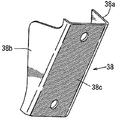
- FIG. 13A is a perspective view showing a stabilizer support bracket 38.
- the stabilizer support bracket 38 connects a pair of side pieces 38a, 38b in the vehicle width direction and these side pieces 38a, 38b.
- the rear piece 38c is integrally formed, and when the assembly of the stabilizer support bracket 38 to the rear subframe 10 (specifically, the rear cross member 12) is completed, the rear piece 38c is inclined in a front, low, and rear height. It is supposed to be.
- the stabilizer 25 is attached to the back surface of the rear piece 38c of the stabilizer support bracket 38 by using a support bracket 39 fastened by bolts and nuts (see FIGS. 6 and 9).
- ridge line X1 extending in the vehicle width direction in the middle of the vehicle width direction, and the upper end of the front front protrusion 12d from the left and right ends of the ridge line X1.
- Ridge lines X2 and X2 extending outward in the vehicle width direction along the ridge lines X3 and X3 extending outward in the vehicle width direction along the upper end of the rear portion of the upper rear protrusion 12e from the connecting portion of the ridge lines X1 and X2.
- These ridgelines X1, X2, and X3 are combined in an approximately X shape in plan view. Thereby, the torsional rigidity of the rear cross member 12 is improved.
- a partition member 40 is provided in the closed cross section S4 near the lower end of the stabilizer support bracket 38 of the rear cross member 12, and the partition member 40 and the upper surface of the lower side member 14 are arranged.
- a lower closed section S6 extending in the vehicle width direction is formed.
- the lower closed cross section S6 By forming the lower closed cross section S6, the local rigidity of the rear cross member 12 in the vehicle width direction is increased, the cross section is made strong against load transmission from the lower arm rear support portions 12b and 12c, and stress is concentrated. Both prevention of deformation and improvement in rigidity in the vehicle width direction are achieved.
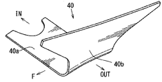
- FIG. 12A is a plan view of the partition member 40
- FIG. 12B is a perspective view of the partition member 40.
- FIG. The partition member 40 is positioned within the closed cross-section S4 of the rear cross member 12 and extends in the vehicle width direction.
- the partition member 40 has a predetermined amount from the outer end in the vehicle width direction of the lower piece 40a in the front-rear width of the rear cross member 12. After extending upward, the front and rear portions are provided with side pieces 40b having an enlarged width, and these pieces 40a, 40b are integrally formed.
- the lower piece 40a is fixed to the front and rear walls of the rear cross member 12 by welding, and as shown in FIG.
- the upper end of the side piece 40b is connected to the lower surface of the upper front protrusion 12d and the upper rear surface. It is fixed by welding to the lower surface of the side protrusion 12e.
- the rear cross member 12 may be formed by combining two members, or may be formed by a hydroformed part.
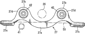
- FIG. 13B is an enlarged front view showing the brace 27.
- the brace 27 includes a central lower bulging portion 27a that bulges downward while avoiding the propeller shaft 26, and both left and right outer sides in the vehicle width direction of the central lower bulging portion 27a.
- the exhaust pipe 41 (provided that the exhaust pipe 41 is provided only on the right side of the vehicle) is provided with a pair of left and right upper bulging portions 27b, 27b that bulge upward, and these are integrally formed.
- the brace 27 is made of aluminum die casting.
- the central lower bulging portion 27a and the left and right upper bulging portions 27b and 27b are smoothly and integrally connected.
- tunnel portion attachment portions 27 c and 27 c (hereinafter simply referred to as attachment portions) extending rearward to the position of the vehicle body attachment portion of the toe control link 20 are integrally formed on both sides of the brace 27 in the vehicle width direction. Is formed.
- the inflection point between the central lower bulging portion 27a and the upper bulging portion 27b is substantially located on an imaginary line that linearly connects the left and right tunnel portion mounting portions 27c and 27c in the vehicle width direction.
- a brace 27 is formed. With this configuration, as shown in FIG. 13B, the brace 27 is formed with a load transmission path 50 that connects the left and right attachment portions 27c, 27c substantially linearly in the vehicle width direction.
- the non-bulged edge of the bulging portion is close to the imaginary line passing through the left and right mounting portions 27c and 27c as shown in FIG.
- the edge on the non-bulged side has a bending amount with respect to the imaginary line that is smaller than the bending amount of the edge on the bulging side, that is, the distance from the imaginary line is small and close to a straight line. preferable.
- the left and right mounting portions 27c, 27c of the brace 27 are avoided while avoiding the propeller shaft 26 and the exhaust pipe 41 even if it is difficult to dispose the thick brace straight in the vehicle width direction.
- a load transmission path 50 that linearly connects the two in the vehicle width direction, and to reinforce the brace 27 itself by the bulged portions 27a and 27b, thereby reinforcing the front cross member 11. It is configured.
- the pair of left and right upper bulges 27b of the brace 27 are provided with differential mount portions 27d that support the differential mount bushing 42, respectively. Accordingly, the differential mount portion 27d is reinforced by the upper bulging portion 27b without increasing the number of parts, thereby enabling support of a rear differential device (not shown). As a result, the front side of the rear differential device is configured such that it is not necessary to separately provide a differential mount bracket.
- a rear differential device (not shown) is supported by a differential mount bushing 42 and a rear differential mount bracket 29 located behind the differential mount bushing 42.
- the brace 27 is lower than the lower arm support portions 32a and 35a formed by the lower portion of the front cross member 11 and the columnar portion 33 provided behind the front cross member 11 in a bottom view. It is connected to the lower side member 14 at the wrapping position.
- the lower side member is configured to overlap the lower arm support portions 32a and 35a in a bottom view by using a plurality of fastening members 43 and 43 such as bolts at positions spaced in the front-rear direction of the attachment portion 27c of the brace 27. 14 is connected and fixed to the bottom surface. Accordingly, the lower arm support portions 32a and 35a are reinforced using the brace 27.
- reference numeral 44 denotes an opening for weight reduction
- FIGS. 6 and 7 reference numeral 45 denotes an opening for assembling the mounting portion 17 d of the lower arm 17, and reference numeral in FIG. 8A.
- Reference numeral 46 denotes an arc-shaped recess for avoiding interference with the spare tire pan.
- the rear sub-frame structure of the above-described embodiment includes the front cross member 11 extending in the vehicle width direction and the pair of left and right side members (upper side member 13, which is connected to the front cross member 11 and extends in the vehicle front-rear direction). 13), and a rear sub-frame structure in which vehicle body attachment portions 15 and 15 are provided at both ends of the front cross member 11 in the vehicle width direction.
- a tunnel portion 11a is provided in the center for insertion of the propeller shaft 26, and a brace 27 is provided for connecting the lower portion of the tunnel portion 11a in the vehicle width direction. The brace 27 avoids the propeller shaft 26 and extends downward.
- An upper bulging portion 27b that bulges upward while avoiding 1 is formed, and the brace 27 is formed with a load transmission path 50 that connects the left and right mounting portions 27c, 27c substantially linearly in the vehicle width direction. (See FIGS. 1, 4 and 13B).
- the left and right attachment portions 27c of the brace 27 can be avoided while avoiding the propeller shaft 26 and the exhaust pipe 41 even if it is difficult to dispose the brace having a large thickness straight in the vehicle width direction.
- 27c can be secured in a straight line in the vehicle width direction, and the braces 27 themselves are reinforced by the bulged portions 27a, 27b. Can be reinforced.
- the upper bulging portion 27b is provided with a diff mount portion 27d that supports the diff mount bush 42 (see FIGS. 4 and 13B).
- the rear subframe 10 includes a rear cross member 12 extending in the vehicle width direction behind the front cross member 11 and a vehicle front-rear direction below the side member (upper side member 13).
- a lower side member 14 that extends, and the brace 27 is disposed between the lower portion of the front cross member 11 and the rear side thereof between the upper portion of the front cross member 11 and the lower side member 14 or above.
- the lower arm support portions 32a and 35a formed by the side member (that is, the upper side member 13) and the columnar portion 33 provided between the lower side member 14 and the lower arm support portions 32a and 35a are overlapped in a bottom view as described above. It is connected to the lower side member 14 (see FIGS. 3 and 8B).
- the lower arm support portions 32a and 35a themselves can be reinforced by the brace 27.
- a rear sub-frame structure includes a rear sub-frame including a front cross member extending in the vehicle width direction and a pair of left and right side members connected to the front cross member and extending in the vehicle front-rear direction.
- a rear sub-frame structure in which vehicle body attachment portions are provided at both ends in the vehicle width direction of the member, and a tunnel portion provided at the lower center of the front cross member so as to pass the propeller shaft, and a vehicle below the tunnel portion.
- a brace extending in the width direction and having a tunnel mounting portion at both left and right ends, the brace being bulged downward by avoiding the propeller shaft, and the central lower bulged portion And an upper bulging portion that bulges upward and avoids the exhaust pipe. Inflection point between the parts and the upper bulging portion is configured to substantially positioned on the virtual line that connects linearly the tunnel portion mounting portion of the left and right in the vehicle width direction.
- the left and right tunnel part mounting portions of the brace are installed in the vehicle while avoiding the propeller shaft and the exhaust pipe even if it is difficult to dispose the thick brace straight in the vehicle width direction. It is possible to secure a load transmission path that is connected substantially linearly in the width direction, and to reinforce the brace itself by the above-mentioned bulging portions, and thus, it is possible to reinforce the front cross member.
- the upward bulging portion is provided with a diff mount portion for supporting the diff mount bush.
- the rear sub frame when the side member is defined as an upper side member, the rear sub frame includes a rear cross member extending in the vehicle width direction behind the front cross member, and a lower side of the upper side member.
- a lower side member extending in the vehicle front-rear direction, and the brace is disposed between the lower portion of the front cross member and the rear side between the upper portion of the front cross member and the lower side member, or
- the lower arm member is connected to the lower side member at a position overlapping the lower arm support portion formed by the columnar portion provided between the upper side member and the lower side member in a bottom view.
- the lower arm support itself can be reinforced by braces.
- the present invention includes a rear subframe including a front cross member extending in the vehicle width direction and a pair of left and right side members connected to the front cross member and extending in the vehicle front-rear direction. This is useful for a rear subframe structure in which vehicle body attachment portions are provided at both ends of the cross member in the vehicle width direction.
Landscapes
- Engineering & Computer Science (AREA)
- Chemical & Material Sciences (AREA)
- Combustion & Propulsion (AREA)
- Transportation (AREA)
- Mechanical Engineering (AREA)
- Body Structure For Vehicles (AREA)
Abstract
リヤサブフレーム構造は、フロントクロスメンバと、該フロントクロスメンバに連結されて車両前後方向に延びる左右一対のサイドメンバとを備えたリヤサブフレームを備え、フロントクロスメンバの車幅方向両端に車体取付け部が設けられる。リヤサブフレームは、プロペラシャフトを通過させるようにフロントクロスメンバの下部中央に設けられたトンネル部と、トンネル部下方において車幅方向に延び、かつ左右両端にトンネル部取り付け部を有するブレースとを備え、該ブレースは、プロペラシャフトを避けて下方に膨出する中央下側膨出部と、該中央下側膨出部の車幅方向外側に連続して設けられ、排気管を避けて上方に膨出する上方膨出部とを含み、中央下側膨出部と上方膨出部との変曲点が、左右のトンネル部取付け部を車幅方向に直線的に繋いだ仮想線上にほぼ位置する。
Description
この発明は、車両のリヤサブフレーム構造に関し、詳しくは、車幅方向に延びるフロントクロスメンバと、該フロントクロスメンバに連結されて車両前後方向に延びる左右一対のサイドメンバとを備えたリヤサブフレームを備え、上記フロントクロスメンバの車幅方向両端に車体取付け部が設けられたリヤサブフレーム構造に関する。
一般に、リヤサブフレームは、車幅方向に延びる前後一対のクロスメンバと、車両前後方向に延びる左右のサイドメンバとを車両平面視で略井桁状に連結して構成される。
上述のリヤサブフレームを、後席乗員の居住性やヒップポイントの低さを追求して、リヤシートパンの高さを低く設定した車両に取付ける場合、リヤサブフレームの前側車体取付け部は、その上方部がリヤシートパンで規制されるうえ、プロペラシャフトや排気管を車両前後方向に配設する必要があるので、リヤサブフレームを構成するフロントクロスメンバが鞍型に形成される場合がある。
この鞍型のフロントクロスメンバの下部を補強するためには、鞍型部位の下方においてブレースを車幅方向に設けることが考えられるが、排気管やプロペラシャフトを上述のリヤシートパンで規制された狭いスペースに設けようとすると、厚みが大きいブレースを車幅方向に真っ直ぐに配設し難いという問題点があった。
特許文献1には、リヤサブフレームに相当するアッパメンバエレメントを設け、このアッパメンバエレメントに車両前後方向にプロペラシャフトを挿通する鞍型部位を形成し、この鞍型部材の下方に、ブレースに相当するロアメンバエレメントを設けたものが開示されている。
しかしながら、該特許文献1に開示された従来構造においては、上述のロアメンバエレメントが正面視で車幅方向に略直線状に形成されている関係上、この従来構造を、リヤシートパンの高さを低く設定した車両に採用しようとすると、排気管のレイアウト性が悪化する問題点があり、改善の余地があった。
そこで、この発明は、厚みが大きいブレースを車幅方向に真っ直ぐに配設することが困難な部位であっても、プロペラシャフトや排気管を回避しつつ、車幅方向に略直線的な荷重伝達経路を確保して、フロントクロスメンバを補強することができるリヤサブフレーム構造の提供を目的とする。
そして、本発明は、車幅方向に延びるフロントクロスメンバと、該フロントクロスメンバに連結されて車両前後方向に延びる左右一対のサイドメンバとを備えたリヤサブフレームを備え、上記フロントクロスメンバの車幅方向両端に車体取付け部が設けられたリヤサブフレーム構造であって、プロペラシャフトを通過させるように上記フロントクロスメンバの下部中央に設けられたトンネル部と、上記トンネル部下方において車幅方向に延び、かつ左右両端にトンネル部取り付け部を有するブレースとを備え、該ブレースは、上記プロペラシャフトを避けて下方に膨出する中央下側膨出部と、該中央下側膨出部の車幅方向外側に連続して設けられ、排気管を避けて上方に膨出する上方膨出部とを含み、上記中央下側膨出部と上方膨出部との変曲点が、上記左右のトンネル部取付け部を車幅方向に直線的に繋いだ仮想線上にほぼ位置するものである。
この発明の一実施形態を以下図面に基づいて詳述する。
図1はリヤサブフレーム構造の斜視図、図2はリヤサブフレーム構造の平面図、図3はリヤサブフレーム構造の底面図、図4はリヤサブフレーム構造の正面図、図5はリヤサブフレーム構造の背面図である。なお、図中、矢印Fは車両前方を示し、矢印Rは車両後方を示し、矢印INは車幅方向の内方を示し、矢印OUTは車幅方向の外方を示す(その他の図についても同様である)。
図1~図5において、リヤサスペンションを支持するリヤサブフレーム10は、前側において車幅方向に延びるフロントクロスメンバ11と、このフロントクロスメンバ11の後方において車幅方向に延びるリヤクロスメンバ12と、これらフロントクロスメンバ11およびリヤクロスメンバ12とを車両前後方向に連結する一対の上側サイドメンバ13,13、並びに、一対の下側サイドメンバ14,14とを含み、これらが車両平面視で略井桁状に連結されたものである。ここで、上述の各メンバ11~14は全て閉断面構造を有している。
この実施形態では、上側サイドメンバ13は、フロントクロスメンバ11の車幅方向側部に、後述する柱状部33(図10参照)を介して連結されており、この連結部から車両後方に延びている。
また、リヤクロスメンバ12は、左右一対の上側サイドメンバ13,13の後部、並びに左右一対の下側サイドメンバ14,14の後部を車幅方向に連結すると共に、上下のサイドメンバ13,14を上下方向に連結している。
下側サイドメンバ14は、図2に示すように、上側サイドメンバ13よりも車幅方向内側に位置し、フロントクロスメンバ11の下部とリヤクロスメンバ12の下部とを車両前後方向に連結している。
図2,図3に示すように、左右一対の下側サイドメンバ14,14の後端部の間隔は、同サイドメンバ14,14の前端部の間隔に対して幅狭に形成されている。これにより後述するロアアーム後側支持部12b,12c(図6参照)が上側サイドメンバ13に平面視でオーバラップする位置に設けられている。
図1~図5に示すように、フロントクロスメンバ11の車幅方向両端には、前側の車体取付け部15,15が設けられている。上側サイドメンバ13の後部は、車両後方かつ車幅方向外方へ滑らかに湾曲形成されており、その後端には、後側の車体取付け部16,16が設けられている。リヤサブフレーム10は、これらの各車体取付け部15,16を介して車体、具体的にはリヤサイドフレームに取付けられる。
符号17はロアアームである。このロアアーム17の車幅方向外端前部にはリンク支持部17aが設けられており、このリンク支持部17aにインテグラルリンク18の下端部が枢支されており、このインテグラルリンク18の上端部はハブサポート19のインテグラルリンク支持部に枢支連結されている。
インテグラルリンク18は、リセッション角(後輪が段差に乗り上げた時、当該後輪が上下方向に移動する側面視の揺動軌跡と、路面との成す角度)をコントロールするためのリンクである。
この実施形態では、ロアアーム17としてH型ロアアームを採用している。該ロアアーム17の車幅方向外端後部には連結部17bが設けられており(図3参照)、当該連結部17bがハブサポート19のロアアーム支持部に枢支連結されている。
符号20は後輪をトーイン(toe-in)に設定してその直進性を確保するためのトーコントロールリンクである。該トーコントロールリンク20の車幅方向外端部には連結部20aが設けられており、該連結部20aがハブサポート19のトーコントロールリンク支持部に枢支連結されている。
符号21はアッパアームである。このアッパアーム21の車幅方向外端部には連結部21aが設けられており、該連結部20aがハブサポート19のアッパアーム支持部に枢支連結されている。この実施形態では、該アッパアーム21としてI型アッパアームを採用している。
図1,図4,図5に示すように、ハブサポート19には車幅方向内側に延びるダンパ支持部19aが一体形成され、このダンパ支持部19aにストラット構造のダンパ22が取付けられている。
図2,図3に示すように、ロアアーム17の後部には後方に膨出する膨出部17cが設けられている。この膨出部17cの上部に取付けたスプリングロアリテーナ23と、車体側のリヤサイドフレームに設けられたスプリングアッパリテーナ(図示せず)との間に、コイルスプリング24が張架されている。
図2,図3,図5に示すように、リヤクロスメンバ12の後方には、該リヤクロスメンバ12に沿うようにスタビライザ25が設けられている。このスタビライザ25は、その左右両端部がロアアーム17上方に位置するように車両前方に向けて屈曲形成されており、該屈曲端部は連結部材を用いてロアアーム17に連結されている。このスタビライザ25は、ねじり剛性の抵抗により片輪のみのバンプ、リバウンド時にロール角を抑制するものである。
図4に示すように、フロントクロスメンバ11の下部中央には、プロペラシャフト26を車両前後方向に挿通するトンネル部11aが設けられている。当該フロントクロスメンバ11は鞍型に形成されている。そして、このトンネル部11aの下部を車幅方向に連結する補強部材としてのブレース27が設けられている。
図1~図3に示すように、リヤクロスメンバ12の車幅方向中間部には、デフマウント部12aが形成されており、このデフマウント部12aにデフマウントブッシュ28を介してデフマウントブラケット29が取付けられている。
この実施形態の車両は、後輪に駆動力を伝達するタイプの車両であって、デフマウントブラケット29でリヤディファレンシャル装置(図示せず)の後部を支持するように構成している。
構成している。
構成している。
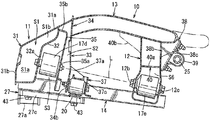
図6はリヤサブフレーム構造を車両左側後方から見た斜視図、図7はリヤサブフレーム構造を車両右上後方から見た斜視図、図8Aは図2のA-A線矢視断面図、図8Bは図2のB-B線矢視断面図、図9は図2のC-C線矢視断面図、図10は図2の要部側面図、図11は図10のD-D線矢視断面図である。
なお、図6~図11は車両左側の構成を示しているが、車両右側の構成は左側の構成と左右対称または左右略対称に形成されている。
図8A,図8B,図9,図11に示すように、フロントクロスメンバ11は、前側に位置するフロントパネル31と後側に位置するリヤパネル32とを接合固定した構造であり、車幅方向に延びる閉断面S1を有している。詳しくは、側面視で、リヤサブフレーム10の中央側(つまり、後方側)のリヤパネル32と、このリヤパネル32よりも上面31aが後方に延びかつ前面31bが下方に延びるフロントパネル31とで閉断面S1が形成されている。
図1,図6に示すように、フロントクロスメンバ11の左右両側部は、車幅方向外方であって、前方かつ下方に傾斜しており、これにより、上記閉断面S1の前部が図8B,図9に示すように、下方に延びて拡大閉断面S1aが形成される一方で、フロントクロスメンバ11の車幅方向側部における閉断面S1の後部が図8B,図9に示すように、上方かつ前方に凹んで凹入閉断面S1bが形成されている。ここで、拡大閉断面S1aと凹入閉断面S1bとは連続するものである。
図6,図8B,図9に示すように、拡大閉断面S1aの後部には、ロアアーム17の前後の取付け部17d,17eのうちの前側の取付け部17dを支持するロアアーム支持部32aが形成されている。
図8Bに示すように、閉断面S1の上部後面、詳しくは、凹入閉断面S1bの後面には、柱状部33を介して、上側サイドメンバ13が連結されている。
このように、フロントクロスメンバ11の車幅方向側部を前方かつ下方に傾斜させることで、リヤシートパン(リヤフロアパネル)との干渉を回避しつつ、閉断面S1の前部を下方に拡大(拡大閉断面S1a参照)して、ロアアーム17の揺動範囲を狭めることなく、車幅方向の剛性を確保したものである。
つまり、フロントクロスメンバ11や上側サイドメンバ13を充分な閉断面構造(直線状に延びる閉断面構造)を確保しつつ連結できないようなリヤシートパン下部の狭い空間に対してリヤサブフレーム10を配設する構造であっても、車幅方向の高剛性化と、ロアアーム支持部32aのスペース確保(詳しくは、ロアアーム17の取付け部17dのスペース確保)との両立を図るように構成されている。
図6,図7,図8Bに示すように、柱状部33は、アッパアーム21の取付け部21b(図2参照)を支持するアッパアーム支持部34aが形成された後板34と、ロアアーム支持部35aを形成する前板35とで構成された閉断面S2形状を有している。なお、後板34は図6,図11に示すように、平面視でコ字状断面を有するように形成されている。
図7に示すように、前板35は、その主面部外周縁から車両前方に延びてフロントクロスメンバ11のリヤパネル32の背面に突き当て溶接されるドーム形状のフランジ部35bを有している。
図8B,図9に示すように、フロントクロスメンバ11の車幅方向側部の閉断面S1と、その直後方に位置する前板35と、下側サイドメンバ14上面とで車幅方向に延びる第2の閉断面S3が形成されている。これにより、ロアアーム支持スペースの確保と、下側サイドメンバ14の連結剛性向上との両立を図るように構成されている。
ここで、図7に示すように、前板35の下部は、下側サイドメンバ14の上面および下側サイドメンバ14の車幅方向外側の側面に突き当て溶接により固定されている。
図8Bに示すように、閉断面S2構造を有する柱状部33は、第2の閉断面S3の直後方に設けられている。該柱状部33は、前板35を含んで下側サイドメンバ14から上方に延びてフロントクロスメンバ11の背面に連結されている。この柱状部33の上部後面、詳しくは、後板34の上部後面は上側サイドメンバ13の前部に溶接にて連結されている。
つまり、ロアアーム支持部32a,35aのうち前側のロアアーム支持部32aは、フロントクロスメンバ11の車幅方向側部において閉断面S1の前部が下方に延びた部位(拡大閉断面S1aの部位)で形成され、後側のロアアーム支持部35aは、閉断面S2構造を有する柱状部33で形成され、かつ上記柱状部33は上側サイドメンバ13と下側サイドメンバ14とフロントクロスメンバ11との全てに連結されている。この構成により、ロアアーム支持部32a,35aを介して入力される荷重の分散が図れ、リヤサブフレーム10の高剛性化が達成されている。
また、フロントクロスメンバ11の車幅方向側部を低くしつつ、充分なロアアーム支持スペースを確保するために、上記凹入閉断面S1bの上下寸法を上側サイドメンバ13の上下方向の寸法よりも薄くしながらも、柱状部33(詳しくは、その後板34)がセットプレートとして用いられることにより連結剛性の向上が図られている。
図6,図7,図8Bに示すように、前板35と後板34とから成り車幅方向および上下方向に延びる縦壁状の上記柱状部33は、フロントクロスメンバ11の車幅方向側部と、上側サイドメンバ13の前端部との間に挟持固定されている。
柱状部33の下部、詳しくは、前板35および後板34の下部は、図6、図7、図8Bに示すように、下側サイドメンバ14の上面および下側サイドメンバ14の車幅方向外側の側面とにそれぞれ連結されている。後板34の上部には、上記アッパアーム支持部34aが形成され、前板35の下部には、上記ロアアーム支持部35aが形成されている。
これにより、上下の各アーム(ロアアーム17、アッパアーム21)からの入力荷重を上下のサイドメンバ13,14やフロントクロスメンバ11に直接伝達して、荷重分散を図ることで、リヤサブフレーム10の高剛性化を達成すると共に、上記柱状部33に上下のアーム支持部34a,35aが形成されていることで、ロアアーム17、アッパアーム21間の位置決め精度の向上が図られている。
図6,図7,図10に示すように、アッパアーム支持部34aはその後部に側面視で略Z字状のアッパアーム支持ブラケット36を備えている。
アッパアーム支持ブラケット36は、上下方向に延びる縦片36aと、この縦片36aの上端から後方に延びる上片36bと、縦片36aの下端から前方に延びる下片36cとを有し、これらの片36a~36cを一体形成したものである。図10に示すように、縦片36aの上側半分と上片36bとは上側サイドメンバ13の車幅方向外側の側面に突き当て溶接されており、下片36cの前端は後板34の背面に突き当て溶接されている。
図10に示すように、アッパアーム支持ブラケット36は、フロントクロスメンバ11と共に柱上部33を挟持している。また、該アッパアーム支持ブラケット36で上側サイドメンバ13前部と柱状部33とを連結している。このような、アッパアーム支持ブラケット36とフロントクロスメンバ11とによる柱状部33の挟持構造により、当該柱状部33を確実に支持させ、柱状部33上部のアッパアーム支持部34aとアッパアーム支持ブラケット36とでアッパアーム21を支持することにより該アッパアーム21の支持剛性を高めている。また、柱状部33と上側サイドメンバ13との連結剛性の向上を図るように構成されている。
図8Bに示すように、柱状部33の後板34の上部はフロントクロスメンバ11(詳しくは、フロントパネル31の上面31aの後部)に直結されており、ロアアーム支持部35a,32aは、前板35の下部とフロントクロスメンバ11の下部(詳しくは、リヤパネル32の下部)とで構成されている。これにより、アッパアーム21およびロアアーム17からの荷重を、フロントクロスメンバ11および上下の各サイドメンバ13,14に伝達して荷重分散を図り、リヤサブフレーム10の高剛性化を達成するように構成されている。
図8B、図10に示すように、柱状部33は上側サイドメンバ13と下側サイドメンバ14との間に上下方向に延設されたもので、該柱状部33のうち、下側サイドメンバ14の上方に位置する前面、つまり、前板35にロアアーム支持部35aが設けられている。
また、図6,図7,図8Bに示すように、ロアアーム支持部35aの下方でかつ下側サイドメンバ14の車幅方向外側方に位置する柱状部33の後面、つまり、後板34にはトーコントロールリンク支持部34bが設けられている。
図6,図7,図11に示すように、リヤサブフレーム10には、トーコントロールリンク支持部34bを後方から支持するトーコントロールリンク支持ブラケット37(以下単に、リンク支持ブラケットと略記する)を設けている。
このリンク支持ブラケット37は、同図に示すように、下側サイドメンバ14の上面に立設固定されて車両前後方向に延びる前片37aと、前片37aの後端から車幅方向外方に延びる側片37cとを有し、これらの片37a、37bが一体形成されたものである。側片37cには、横向き凹状の切欠き部37bが形成されており、側片37cは、この切欠き部37bが下側サイドメンバ14の上面、外側面、下面に溶接固定されている。
そして、このリンク支持ブラケット37が、下側サイドメンバ14と柱状部33のロアアーム支持部35aの背面との間に架設されている。
ロアアーム支持部35aと、トーコントロールリンク支持部34bとは上下方向にずらしたレイアウトとされており、これにより各支持部35a,34bおよびロアアーム17と、トーコントロールリンク20とのコンパクトな集約配置を達成し、さらに、これらロアアーム17、トーコントロールリンク20からの荷重を下側サイドメンバ14の上面と側面とに分散させると共に、上下の各サイドメンバ13,14にも分散させることにより、リヤサブフレーム10の高剛性化が図られている。加えて、柱状部33がロアアーム17とトーコントロールリンク20との2部品を支持することで、ロアアーム17とトーコントロールリンク20との間の位置決め精度が高まるように構成されている。
ここで、第1アーム支持部が、ロアアーム17を支持するロアアーム支持部35aに設定されることで、ロアアーム17の前側取付け部17dを下側サイドメンバ14の車幅方向外側の側縁よりも車幅方向内側までオフセットさせて配置することができ、図8Bに示す仮想的なロアアーム揺動中心線Lの設定自由度の向上を図るように構成されている。
図8Bに示すように、ロアアーム支持部35aで支持されるロアアーム17はその前後両部に車体取付け部17d,17eが設けられている。すなわち、該ロアアーム17はそのアーム揺動中心側の前側に前側取付け部17dを備えており、そのアーム揺動中心側の後側に後側取付け部17eを備えている。
そして、上記リヤクロスメンバ12と連結または一体に形成されたロアアーム後側支持部12b,12cが、柱状部33のロアアーム支持部35aよりも下方で、かつロアアーム17の前後の取付け部17d,17eを通る第1アーム揺動中心線Lがリンク支持部34bよりも上方になるように設けられている。
図8Bに示すように、上下のサイドメンバ13,14がリヤクロスメンバ12で上下に連結されており、頑強な箱形構造を形成している。また、リヤクロスメンバ12の下部にロアアーム17の後側支持部12b,12cが設けられており、ロアアーム17の荷重を前後の取付け部17d,17eを介して前後に分散させ、かつ、ロアアーム17の前後の取付け部17d,17eがリセッション角を得るための角度をもってリンク支持部34bよりも上方にロアアーム揺動中心線L(仮想軸)が形成されている。これにより、リヤシートパンが近接するような狭い空間であっても、ロアアーム前側支持部35aとリンク支持部34bとが強固に形成されている。
すなわち、ロアアーム17の支持部で支持剛性を高めつつ、トーコントロールリンク20との干渉を回避して、リセッション角の設定が容易となるよう構成したものである。
図9,図10に示すように、上側サイドメンバ13と下側サイドメンバ14とを上下方向に連結するリヤクロスメンバ12は、上側サイドメンバ13の車幅方向内側の側面に沿って車両前後方向に拡幅された側面視T字状の閉断面S4構造(換言すれば、側面視T字状の内部中空構造)を有している。
但し、図1,図2に示すように、この側面視T字状の閉断面S4は、リヤクロスメンバ12の左右両サイド部分にのみ形成されており、リヤクロスメンバ12の車幅方向中間部には、図8Aに示すように、上下方向に延びる側面視I字状の閉断面S5が形成されている。ここで、各閉断面S4,S5は連通するものである。
また、図9に示すように、側面視T字状の閉断面S4と対応するリヤクロスメンバ12の車幅方向側部下側には、ロアアーム後側支持部12b,12cが設けられており、これらの各ロアアーム後側支持部12b,12cによりロアアーム17の後側取付け部17eを支持するように構成している。
側面視T字状の閉断面S4を形成したリヤクロスメンバ12は、その上部に上面前側突出部12dと上面後側突出部12eとが車両前後方向に張り出し形成されており、この上面後側突出部12eと、前後一対のロアアーム後側支持部12b,12cのうちの後側のロアアーム後側支持部12c(この実施形態では、後側のロアアーム後側支持部12cの近傍)との間には、スタビライザ支持ブラケット38が架け渡されている。
このように、リヤクロスメンバ12を側面視T字状の閉断面S4構造とすることで、リヤクロスメンバ12の閉断面大型化と剛性向上とを図り、かつ、リヤクロスメンバ12の上面後側突出部12eとロアアーム支持部12cとの間にスタビライザ支持ブラケット38を架け渡すことで、該スタビライザ支持ブラケット38にてリヤクロスメンバ12を補強し、部品点数を増加することなく、スタビライザ25の配設スペースを確保するよう構成されている。
図13Aはスタビライザ支持ブラケット38を示す斜視図であって、同図に示すように、該スタビライザ支持ブラケット38は、車幅方向内外一対の側片38a,38bと、これら側片38a,38bを連結する後片38cとを一体形成したものであり、スタビライザ支持ブラケット38のリヤサブフレーム10(詳しくは、リヤクロスメンバ12)への組付け完了時には、上記後片38cが前低後高状に傾斜するようになっている。
ここで、スタビライザ25は、スタビライザ支持ブラケット38の後片38c背面に、ボルト、ナットにより締結されるサポートブラケット39を用いて、取付けられる(図6,図9参照)。
図1,図2に示すように、リヤクロスメンバ12の頂部には、車幅方向中間において車幅方向に延びる稜線X1と、この稜線X1の左右両端部から上面前側突出部12dの前部上端に沿って車幅方向外方に延びる稜線X2,X2と、これら各稜線X1,X2の接続部位から上面後側突出部12eの後部上端に沿って車幅方向外方に延びる稜線X3,X3と、が形成されており、これらの各稜線X1,X2,X3は平面視で概ねX字状に組合わされている。これにより、リヤクロスメンバ12の捩り剛性の向上を図るように構成している。
図9,図10に示すように、リヤクロスメンバ12のスタビライザ支持ブラケット38下端近傍において、閉断面S4内には隔壁部材40が設けられており、この隔壁部材40と下側サイドメンバ14上面とで車幅方向に延びる下部閉断面S6が形成されている。
下部閉断面S6の形成により、リヤクロスメンバ12の車幅方向の局部的な剛性を高め、ロアアーム後側支持部12b,12cからの荷重伝達に対して強く成し、応力が集中することによる断面変形の防止と、車幅方向剛性向上との両立が図られている。
図12Aは隔壁部材40の平面図、図12Bは隔壁部材40の斜視図である。この隔壁部材40は、リヤクロスメンバ12の閉断面S4内に位置して車幅方向に延びる下片40aと、この下片40aの車幅方向外端からリヤクロスメンバ12の前後幅で所定量上方に延びた後に、前後両部が拡幅形成された側片40bとを備え、これら片40a、40bが一体形成されたものある。図11に示すように、下片40aはリヤクロスメンバ12の前後両壁に溶接固定されており、図9に示すように、側片40bの上端は上面前側突出部12dの下面と、上面後側突出部12eの下面とに溶接固定されている。リヤクロスメンバ12は2部材を組合せて形成してもよく、或は、ハイドロフォーム成形部品により形成してもよい。
図13Bはブレース27を拡大して示す正面図である。図4,図13Bに示すように、該ブレース27は、プロペラシャフト26を避けて下方に膨出する中央下側膨出部27aと、この中央下側膨出部27aの車幅方向左右両外側において排気管41(但し、排気管41は車両右側にのみ設けられる)を避けて上方に膨出する左右一対の上方膨出部27b,27bとを備え、これらが一体形成されたものである。この実施形態では、ブレース27はアルミダイカストにより構成されている。
図13Bに示すように、中央下側膨出部27aと、その左右の上方膨出部27b,27bとは滑らかに一体に連結されている。
ブレース27の車幅方向両側部には、図3に示すように、トーコントロールリンク20の車体取付け部の位置まで後方に延びるトンネル部取付け部27c,27c(以下単に取付け部と略記する)が一体形成されている。
そして、中央下側膨出部27aと上方膨出部27bとの変曲点が、上記左右のトンネル部取付け部27c,27cを車幅方向に直線的に繋いだ仮想線上にほぼ位置するようにブレース27が形成されている。この構成により、このブレース27には、図13Bに示すように、左右の取付け部27c,27cを車幅方向に略直線的に連結する荷重伝達経路50が形成されている。
具体的には、図13Bに示されるような左右の取付け部27c,27cを通る仮想線上に膨出部の非膨出側の縁が近接することが好ましく、重なるのが更に好ましい。また重ならずに近接する場合、非膨出側の縁は、仮想線に対する屈曲量が、膨出側の縁の屈曲量よりも小さい、すなわち仮想線からの離間距離が小さく直線に近いことが好ましい。
これにより、厚みが大きいブレースを車幅方向に真っ直ぐに配設することが困難な部位であっても、プロペラシャフト26や排気管41を回避しつつ、上記ブレース27の左右の取付け部27c,27cを車幅方向に直線的に連結する荷重伝達経路50を確保し、かつ上記各膨出部27a,27bによりブレース27それ自体の補強を行なって、延いては、フロントクロスメンバ11を補強するよう構成されている。
図4,図13Bに示すように、ブレース27の左右一対の上方膨出部27bには、デフマウントブッシュ42を支持するデフマウント部27dがそれぞれ設けられている。これにより、部品点数を増加することなく、デフマウント部27dを上方膨出部27bにて補強して、リヤディファレンシャル装置(図示せず)の支持を可能としている。これにより、当該リヤディファレンシャル装置の前側においては、別途、デフマウントブラケットを設ける必要がないよう構成されている。
図2で示すように、リヤディファレンシャル装置(図示せず)はデフマウントブッシュ42と、その後方に位置するリヤ側のデフマウントブラケット29とで支持される。
図3,図8Bに示すように、ブレース27は、フロントクロスメンバ11の下部と、その後方に設けられた柱状部33とで形成されたロアアーム支持部32a,35aに対して、下面視でオーバラップする位置において下側サイドメンバ14に連結されている。
すなわち、ブレース27の取付け部27cを、その前後方向に離間した位置においてボルト等の複数の締結部材43,43を用いて、ロアアーム支持部32a,35aと下面視でオーバラップすべく下側サイドメンバ14の底面に連結固定している。これにより、ブレース27を用いてロアアーム支持部32a,35aを補強するよう構成されている。
なお、図1,図5において、符号44は軽量化用の開口部、図6,図7において、符号45はロアアーム17の取付け部17dを組付け作業するための開口部、図8Aにおいて、符号46はスペアタイヤパンとの干渉を回避するための円弧状の凹部である。
このように、上記実施例のリヤサブフレーム構造は、車幅方向に延びるフロントクロスメンバ11と、該フロントクロスメンバ11に連結されて車両前後方向に延びる左右一対のサイドメンバ(上側サイドメンバ13,13参照)とを備えたリヤサブフレーム10を設け、上記フロントクロスメンバ11の車幅方向両端に車体取付け部15,15が設けられたリヤサブフレーム構造であって、上記フロントクロスメンバ11の下部中央にはプロペラシャフト26を挿通するトンネル部11aが設けられており、上記トンネル部11a下部を車幅方向に連結するブレース27が設けられ、該ブレース27は、上記プロペラシャフト26を避けて下方に膨出する中央下側膨出部27aと、該中央下側膨出部27aの車幅方向外側において排気管41を避けて上方に膨出する上方膨出部27bとが形成され、上記ブレース27には、左右の取付け部27c,27cを車幅方向に略直線的に連結する荷重伝達経路50が形成されたものである(図1,図4,図13B参照)。
この構成によれば、厚みが大きいブレースを車幅方向に真っ直ぐに配設することが困難な部位であっても、プロペラシャフト26や排気管41を回避しつつ、ブレース27の左右の取付け部27c,27cを車幅方向に直線的に連結する荷重伝達経路50を確保することができると共に、上記各膨出部27a,27bによりブレース27それ自体の補強を行ない、延いては、フロントクロスメンバ11を補強することができる。
この発明の一実施形態においては、上記上方膨出部27bには、デフマウントブッシュ42を支持するデフマウント部27dが設けられたものである(図4,図13B参照)。
この構成によれば、部品点数を増加することなく、デフマウント部27dを上方膨出部27bにて補強して、リヤディファレンシャル装置の支持が可能となり、かつ別途、デフマウントブラケットを設ける必要もない。
この発明の一実施形態においては、上記リヤサブフレーム10は、フロントクロスメンバ11の後方において車幅方向に延びるリヤクロスメンバ12と、上記サイドメンバ(上側サイドメンバ13)の下方において車両前後方向に延びる下側サイドメンバ14とを、さらに備えており、上記ブレース27は、上記フロントクロスメンバ11下部と、その後方で、上記フロントクロスメンバ11の上部と下側サイドメンバ14との間、または上記サイドメンバ(つまり、上側サイドメンバ13)と下側サイドメンバ14との間に設けられた柱状部33とで形成されたロアアーム支持部32a,35aに対して、下面視でオーバラップする位置において上記下側サイドメンバ14に連結されたものである(図3,図8B参照)。
この構成によれば、ブレース27によりロアアーム支持部32a,35aそれ自体の補強を行なうことができる。
以上説明した本発明をまとめると以下の通りである。
この発明によるリヤサブフレーム構造は、車幅方向に延びるフロントクロスメンバと、該フロントクロスメンバに連結されて車両前後方向に延びる左右一対のサイドメンバとを備えたリヤサブフレームを備え、上記フロントクロスメンバの車幅方向両端に車体取付け部が設けられたリヤサブフレーム構造であって、プロペラシャフトを通過させるように上記フロントクロスメンバの下部中央に設けられたトンネル部と、上記トンネル部下方において車幅方向に延び、かつ左右両端にトンネル部取り付け部を有するブレースとを備え、該ブレースは、上記プロペラシャフトを避けて下方に膨出する中央下側膨出部と、該中央下側膨出部の車幅方向外側に連続して設けられ、排気管を避けて上方に膨出する上方膨出部とを含み、上記中央下側膨出部と上方膨出部との変曲点が、上記左右のトンネル部取付部を車幅方向に直線的に繋いだ仮想線上にほぼ位置するものである。
上記構成によれば、厚みが大きいブレースを車幅方向に真っ直ぐに配設することが困難な部位であっても、プロペラシャフトや排気管を回避しつつ、ブレースの左右のトンネル部取付け部を車幅方向に略直線的に連結する荷重伝達経路を確保することができると共に、上記各膨出部によりブレースそれ自体の補強を行ない、延いては、フロントクロスメンバを補強することができる。
この発明の一実施態様においては、上記上方膨出部には、デフマウントブッシュを支持するデフマウント部が設けられたものである。
上記構成によれば、部品点数を増加することなく、デフマウント部を膨出部にて補強して、リヤディファレンシャル装置の支持が可能となり、かつ別途、デフマウントブラケットを設ける必要もない。
この発明の一実施態様においては、上記サイドメンバを上側サイドメンバと定義したときに、上記リヤサブフレームは、フロントクロスメンバの後方において車幅方向に延びるリヤクロスメンバと、上記上側サイドメンバの下方において車両前後方向に延びる下側サイドメンバとを、さらに備えており、上記ブレースは、上記フロントクロスメンバ下部と、その後方で、上記フロントクロスメンバの上部と下側サイドメンバとの間、または上記上側サイドメンバと下側サイドメンバとの間に設けられた柱状部とで形成されたロアアーム支持部に対して、下面視でオーバラップする位置において上記下側サイドメンバに連結されたものである。
上記構成によれば、ブレースによりロアアーム支持部それ自体の補強を行なうことができる。
以上説明したように、本発明は、車幅方向に延びるフロントクロスメンバと、該フロントクロスメンバに連結されて車両前後方向に延びる左右一対のサイドメンバとを備えたリヤサブフレームを備え、上記フロントクロスメンバの車幅方向両端に車体取付け部が設けられたリヤサブフレーム構造について有用である。
Claims (3)
- 車幅方向に延びるフロントクロスメンバと、該フロントクロスメンバに連結されて車両前後方向に延びる左右一対のサイドメンバとを備えたリヤサブフレームを備え、上記フロントクロスメンバの車幅方向両端に車体取付け部が設けられたリヤサブフレーム構造であって、
プロペラシャフトを通過させるように上記フロントクロスメンバの下部中央に設けられたトンネル部と、
上記トンネル部下方において車幅方向に延び、かつ左右両端にトンネル部取り付け部を有するブレースとを備え、
該ブレースは、上記プロペラシャフトを避けて下方に膨出する中央下側膨出部と、該中央下側膨出部の車幅方向外側に連続して設けられ、排気管を避けて上方に膨出する上方膨出部とを含み、
上記中央下側膨出部と上方膨出部との変曲点が、上記左右のトンネル部取付け部を車幅方向に直線的に繋いだ仮想線上にほぼ位置する、ことを特徴とするリヤサブフレーム構造。 - 請求項1に記載のリヤサブフレーム構造において、
上記上方膨出部には、デフマウントブッシュを支持するデフマウント部が設けられた、リヤサブフレーム構造。 - 請求項1又は2に記載のリヤサブフレーム構造において、
上記サイドメンバを上側サイドメンバと定義したときに、
上記リヤサブフレームは、フロントクロスメンバの後方において車幅方向に延びるリヤクロスメンバと、上記上側サイドメンバの下方において車両前後方向に延びる下側サイドメンバとを、さらに備えており、
上記ブレースは、上記フロントクロスメンバ下部と、その後方で、上記フロントクロスメンバの上部と下側サイドメンバとの間、または上記上側サイドメンバと下側サイドメンバとの間に設けられた柱状部とで形成されたロアアーム支持部に対して、下面視でオーバラップする位置において上記下側サイドメンバに連結された、リヤサブフレーム構造。
Priority Applications (3)
| Application Number | Priority Date | Filing Date | Title |
|---|---|---|---|
| DE112016005160.3T DE112016005160T5 (de) | 2015-11-11 | 2016-11-02 | Hinterteilrahmenstruktur |
| US15/761,925 US10618556B2 (en) | 2015-11-11 | 2016-11-02 | Rear subframe structure |
| CN201680055173.0A CN108367780A (zh) | 2015-11-11 | 2016-11-02 | 后副车架结构 |
Applications Claiming Priority (2)
| Application Number | Priority Date | Filing Date | Title |
|---|---|---|---|
| JP2015-221309 | 2015-11-11 | ||
| JP2015221309A JP6237749B2 (ja) | 2015-11-11 | 2015-11-11 | リヤサブフレーム構造 |
Publications (1)
| Publication Number | Publication Date |
|---|---|
| WO2017082151A1 true WO2017082151A1 (ja) | 2017-05-18 |
Family
ID=58695260
Family Applications (1)
| Application Number | Title | Priority Date | Filing Date |
|---|---|---|---|
| PCT/JP2016/082707 Ceased WO2017082151A1 (ja) | 2015-11-11 | 2016-11-02 | リヤサブフレーム構造 |
Country Status (5)
| Country | Link |
|---|---|
| US (1) | US10618556B2 (ja) |
| JP (1) | JP6237749B2 (ja) |
| CN (1) | CN108367780A (ja) |
| DE (1) | DE112016005160T5 (ja) |
| WO (1) | WO2017082151A1 (ja) |
Cited By (1)
| Publication number | Priority date | Publication date | Assignee | Title |
|---|---|---|---|---|
| US12686441B1 (en) * | 2025-03-11 | 2026-07-21 | Hyundai Motor Company | Rear subframe for vehicle |
Families Citing this family (8)
| Publication number | Priority date | Publication date | Assignee | Title |
|---|---|---|---|---|
| JP6269636B2 (ja) * | 2015-11-10 | 2018-01-31 | マツダ株式会社 | リヤサブフレーム構造 |
| JP6269638B2 (ja) * | 2015-11-11 | 2018-01-31 | マツダ株式会社 | リヤサブフレーム構造 |
| JP6274187B2 (ja) * | 2015-11-11 | 2018-02-07 | マツダ株式会社 | リヤサブフレーム構造 |
| DE102016220786B4 (de) * | 2016-10-24 | 2024-03-28 | Ford Global Technologies, Llc | Hinterradaufhängung für Kraftfahrzeuge |
| JP6778725B2 (ja) * | 2018-09-12 | 2020-11-04 | 本田技研工業株式会社 | 車両 |
| JP2022157768A (ja) * | 2021-03-31 | 2022-10-14 | 本田技研工業株式会社 | サブフレーム |
| JP7582137B2 (ja) | 2021-09-15 | 2024-11-13 | トヨタ自動車株式会社 | 車両のサブフレーム構造 |
| CN117002241B (zh) * | 2022-03-31 | 2026-04-03 | 比亚迪股份有限公司 | 车辆 |
Citations (2)
| Publication number | Priority date | Publication date | Assignee | Title |
|---|---|---|---|---|
| JP2008189264A (ja) * | 2007-02-07 | 2008-08-21 | Toyota Motor Corp | デファレンシャル懸架構造 |
| JP2011020465A (ja) * | 2009-07-13 | 2011-02-03 | Honda Motor Co Ltd | 車両用リヤサブフレーム構造 |
Family Cites Families (23)
| Publication number | Priority date | Publication date | Assignee | Title |
|---|---|---|---|---|
| JP3132511B2 (ja) | 1991-01-10 | 2001-02-05 | マツダ株式会社 | 自動車のサスペンション支持構造 |
| SE508519C2 (sv) | 1994-06-28 | 1998-10-12 | Volvo Ab | Hjulupphängning för ett par drivna fordonshjul |
| DE19529334C2 (de) * | 1994-08-18 | 1997-06-26 | Honda Motor Co Ltd | Unterrahmen für ein Kraftfahrzeug |
| JP3864474B2 (ja) * | 1996-12-10 | 2006-12-27 | マツダ株式会社 | 車両のクロスメンバ構造 |
| US20050011640A1 (en) * | 2003-07-17 | 2005-01-20 | Mazda Motor Corporation | Air conditioner for vehicle |
| US20050061573A1 (en) * | 2003-09-18 | 2005-03-24 | Nissan Motor Co., Ltd. | Vehicle drive system |
| US7140642B2 (en) * | 2004-02-12 | 2006-11-28 | Mazda Motor Corporation | Fuel tank disposition structure of vehicle |
| JP4165437B2 (ja) * | 2004-04-16 | 2008-10-15 | トヨタ自動車株式会社 | パワートレーン |
| JP4905837B2 (ja) * | 2007-10-03 | 2012-03-28 | スズキ株式会社 | 車両の下部構造 |
| JP2009202857A (ja) * | 2008-01-31 | 2009-09-10 | Nissan Motor Co Ltd | 操舵装置の取付け構造 |
| US8353381B2 (en) * | 2009-02-11 | 2013-01-15 | Scott Melvin | Transmission cross-member |
| JP5586089B2 (ja) * | 2010-07-06 | 2014-09-10 | 富士重工業株式会社 | 車体補剛装置 |
| KR101744996B1 (ko) * | 2011-08-11 | 2017-06-08 | 현대자동차주식회사 | 차량의 센터 플로어 판넬 어셈블리 |
| JP5807519B2 (ja) | 2011-11-11 | 2015-11-10 | マツダ株式会社 | 自動車の後部車体構造 |
| JP5499055B2 (ja) * | 2012-01-06 | 2014-05-21 | 富士重工業株式会社 | エンジン電気ハイブリッド車両のバッテリ及び燃料タンク搭載構造 |
| JP5987341B2 (ja) | 2012-02-17 | 2016-09-07 | マツダ株式会社 | リヤサブフレームの車体取付け構造 |
| JP5935686B2 (ja) * | 2012-12-28 | 2016-06-15 | マツダ株式会社 | 自動車のサブフレーム構造 |
| JP6079662B2 (ja) * | 2014-02-14 | 2017-02-15 | トヨタ自動車株式会社 | 車体下部構造 |
| JP6052512B2 (ja) * | 2014-02-20 | 2016-12-27 | マツダ株式会社 | 自動車のリヤサブフレーム構造 |
| US9499205B1 (en) * | 2015-09-23 | 2016-11-22 | Ford Global Technologies, Llc | Hybrid vehicle packaging system |
| JP6269636B2 (ja) * | 2015-11-10 | 2018-01-31 | マツダ株式会社 | リヤサブフレーム構造 |
| JP6274187B2 (ja) * | 2015-11-11 | 2018-02-07 | マツダ株式会社 | リヤサブフレーム構造 |
| JP6269637B2 (ja) * | 2015-11-11 | 2018-01-31 | マツダ株式会社 | リヤサブフレーム構造 |
-
2015
- 2015-11-11 JP JP2015221309A patent/JP6237749B2/ja not_active Expired - Fee Related
-
2016
- 2016-11-02 DE DE112016005160.3T patent/DE112016005160T5/de not_active Withdrawn
- 2016-11-02 WO PCT/JP2016/082707 patent/WO2017082151A1/ja not_active Ceased
- 2016-11-02 US US15/761,925 patent/US10618556B2/en active Active
- 2016-11-02 CN CN201680055173.0A patent/CN108367780A/zh active Pending
Patent Citations (2)
| Publication number | Priority date | Publication date | Assignee | Title |
|---|---|---|---|---|
| JP2008189264A (ja) * | 2007-02-07 | 2008-08-21 | Toyota Motor Corp | デファレンシャル懸架構造 |
| JP2011020465A (ja) * | 2009-07-13 | 2011-02-03 | Honda Motor Co Ltd | 車両用リヤサブフレーム構造 |
Cited By (1)
| Publication number | Priority date | Publication date | Assignee | Title |
|---|---|---|---|---|
| US12686441B1 (en) * | 2025-03-11 | 2026-07-21 | Hyundai Motor Company | Rear subframe for vehicle |
Also Published As
| Publication number | Publication date |
|---|---|
| US10618556B2 (en) | 2020-04-14 |
| US20180273093A1 (en) | 2018-09-27 |
| JP6237749B2 (ja) | 2017-11-29 |
| CN108367780A (zh) | 2018-08-03 |
| JP2017087995A (ja) | 2017-05-25 |
| DE112016005160T5 (de) | 2018-07-26 |
Similar Documents
| Publication | Publication Date | Title |
|---|---|---|
| JP6269638B2 (ja) | リヤサブフレーム構造 | |
| JP6269636B2 (ja) | リヤサブフレーム構造 | |
| JP6237749B2 (ja) | リヤサブフレーム構造 | |
| JP6269637B2 (ja) | リヤサブフレーム構造 | |
| JP6052120B2 (ja) | 車体前部構造 | |
| JP6274187B2 (ja) | リヤサブフレーム構造 | |
| JP5493971B2 (ja) | 車両の後部車体構造 | |
| JP7067365B2 (ja) | 車両の前部車体構造 | |
| JP2012006544A (ja) | 車両の下部車体構造 | |
| JP5061512B2 (ja) | サスペンションフレーム構造 | |
| JP2015128982A (ja) | 車体後部構造 | |
| JP6091876B2 (ja) | 自動車のサスペンションメンバ補強構造 | |
| JP2007161152A (ja) | 車両の後部車体構造 | |
| JP4044803B2 (ja) | 車両のスタビライザ取付構造 | |
| JP4175498B2 (ja) | 車両の下部車体構造 | |
| JP5514855B2 (ja) | 車両の排気系支持構造 | |
| JP2020157983A (ja) | 車両のサイドメンバ構造 | |
| JP6052122B2 (ja) | 車体前部構造 |
Legal Events
| Date | Code | Title | Description |
|---|---|---|---|
| 121 | Ep: the epo has been informed by wipo that ep was designated in this application |
Ref document number: 16864114 Country of ref document: EP Kind code of ref document: A1 |
|
| WWE | Wipo information: entry into national phase |
Ref document number: 15761925 Country of ref document: US |
|
| WWE | Wipo information: entry into national phase |
Ref document number: 112016005160 Country of ref document: DE |
|
| 122 | Ep: pct application non-entry in european phase |
Ref document number: 16864114 Country of ref document: EP Kind code of ref document: A1 |