WO2017082027A1 - 圧粉成形体、電磁部品、及び圧粉成形体の製造方法 - Google Patents
圧粉成形体、電磁部品、及び圧粉成形体の製造方法 Download PDFInfo
- Publication number
- WO2017082027A1 WO2017082027A1 PCT/JP2016/081412 JP2016081412W WO2017082027A1 WO 2017082027 A1 WO2017082027 A1 WO 2017082027A1 JP 2016081412 W JP2016081412 W JP 2016081412W WO 2017082027 A1 WO2017082027 A1 WO 2017082027A1
- Authority
- WO
- WIPO (PCT)
- Prior art keywords
- volume
- iron
- less
- green compact
- oxide film
- Prior art date
Links
Images

Classifications
-
- H—ELECTRICITY
- H01—ELECTRIC ELEMENTS
- H01F—MAGNETS; INDUCTANCES; TRANSFORMERS; SELECTION OF MATERIALS FOR THEIR MAGNETIC PROPERTIES
- H01F1/00—Magnets or magnetic bodies characterised by the magnetic materials therefor; Selection of materials for their magnetic properties
- H01F1/01—Magnets or magnetic bodies characterised by the magnetic materials therefor; Selection of materials for their magnetic properties of inorganic materials
- H01F1/03—Magnets or magnetic bodies characterised by the magnetic materials therefor; Selection of materials for their magnetic properties of inorganic materials characterised by their coercivity
- H01F1/12—Magnets or magnetic bodies characterised by the magnetic materials therefor; Selection of materials for their magnetic properties of inorganic materials characterised by their coercivity of soft-magnetic materials
- H01F1/14—Magnets or magnetic bodies characterised by the magnetic materials therefor; Selection of materials for their magnetic properties of inorganic materials characterised by their coercivity of soft-magnetic materials metals or alloys
- H01F1/20—Magnets or magnetic bodies characterised by the magnetic materials therefor; Selection of materials for their magnetic properties of inorganic materials characterised by their coercivity of soft-magnetic materials metals or alloys in the form of particles, e.g. powder
- H01F1/22—Magnets or magnetic bodies characterised by the magnetic materials therefor; Selection of materials for their magnetic properties of inorganic materials characterised by their coercivity of soft-magnetic materials metals or alloys in the form of particles, e.g. powder pressed, sintered, or bound together
- H01F1/24—Magnets or magnetic bodies characterised by the magnetic materials therefor; Selection of materials for their magnetic properties of inorganic materials characterised by their coercivity of soft-magnetic materials metals or alloys in the form of particles, e.g. powder pressed, sintered, or bound together the particles being insulated
-
- B—PERFORMING OPERATIONS; TRANSPORTING
- B22—CASTING; POWDER METALLURGY
- B22F—WORKING METALLIC POWDER; MANUFACTURE OF ARTICLES FROM METALLIC POWDER; MAKING METALLIC POWDER; APPARATUS OR DEVICES SPECIALLY ADAPTED FOR METALLIC POWDER
- B22F1/00—Metallic powder; Treatment of metallic powder, e.g. to facilitate working or to improve properties
- B22F1/10—Metallic powder containing lubricating or binding agents; Metallic powder containing organic material
-
- B—PERFORMING OPERATIONS; TRANSPORTING
- B22—CASTING; POWDER METALLURGY
- B22F—WORKING METALLIC POWDER; MANUFACTURE OF ARTICLES FROM METALLIC POWDER; MAKING METALLIC POWDER; APPARATUS OR DEVICES SPECIALLY ADAPTED FOR METALLIC POWDER
- B22F3/00—Manufacture of workpieces or articles from metallic powder characterised by the manner of compacting or sintering; Apparatus specially adapted therefor ; Presses and furnaces
- B22F3/02—Compacting only
-
- B—PERFORMING OPERATIONS; TRANSPORTING
- B22—CASTING; POWDER METALLURGY
- B22F—WORKING METALLIC POWDER; MANUFACTURE OF ARTICLES FROM METALLIC POWDER; MAKING METALLIC POWDER; APPARATUS OR DEVICES SPECIALLY ADAPTED FOR METALLIC POWDER
- B22F3/00—Manufacture of workpieces or articles from metallic powder characterised by the manner of compacting or sintering; Apparatus specially adapted therefor ; Presses and furnaces
- B22F3/24—After-treatment of workpieces or articles
-
- H—ELECTRICITY
- H01—ELECTRIC ELEMENTS
- H01F—MAGNETS; INDUCTANCES; TRANSFORMERS; SELECTION OF MATERIALS FOR THEIR MAGNETIC PROPERTIES
- H01F1/00—Magnets or magnetic bodies characterised by the magnetic materials therefor; Selection of materials for their magnetic properties
- H01F1/01—Magnets or magnetic bodies characterised by the magnetic materials therefor; Selection of materials for their magnetic properties of inorganic materials
- H01F1/03—Magnets or magnetic bodies characterised by the magnetic materials therefor; Selection of materials for their magnetic properties of inorganic materials characterised by their coercivity
- H01F1/12—Magnets or magnetic bodies characterised by the magnetic materials therefor; Selection of materials for their magnetic properties of inorganic materials characterised by their coercivity of soft-magnetic materials
- H01F1/33—Magnets or magnetic bodies characterised by the magnetic materials therefor; Selection of materials for their magnetic properties of inorganic materials characterised by their coercivity of soft-magnetic materials mixtures of metallic and non-metallic particles; metallic particles having oxide skin
-
- H—ELECTRICITY
- H01—ELECTRIC ELEMENTS
- H01F—MAGNETS; INDUCTANCES; TRANSFORMERS; SELECTION OF MATERIALS FOR THEIR MAGNETIC PROPERTIES
- H01F1/00—Magnets or magnetic bodies characterised by the magnetic materials therefor; Selection of materials for their magnetic properties
- H01F1/01—Magnets or magnetic bodies characterised by the magnetic materials therefor; Selection of materials for their magnetic properties of inorganic materials
- H01F1/03—Magnets or magnetic bodies characterised by the magnetic materials therefor; Selection of materials for their magnetic properties of inorganic materials characterised by their coercivity
- H01F1/12—Magnets or magnetic bodies characterised by the magnetic materials therefor; Selection of materials for their magnetic properties of inorganic materials characterised by their coercivity of soft-magnetic materials
- H01F1/34—Magnets or magnetic bodies characterised by the magnetic materials therefor; Selection of materials for their magnetic properties of inorganic materials characterised by their coercivity of soft-magnetic materials non-metallic substances, e.g. ferrites
- H01F1/342—Oxides
- H01F1/344—Ferrites, e.g. having a cubic spinel structure (X2+O)(Y23+O3), e.g. magnetite Fe3O4
-
- H—ELECTRICITY
- H01—ELECTRIC ELEMENTS
- H01F—MAGNETS; INDUCTANCES; TRANSFORMERS; SELECTION OF MATERIALS FOR THEIR MAGNETIC PROPERTIES
- H01F27/00—Details of transformers or inductances, in general
- H01F27/24—Magnetic cores
- H01F27/255—Magnetic cores made from particles
-
- H—ELECTRICITY
- H01—ELECTRIC ELEMENTS
- H01F—MAGNETS; INDUCTANCES; TRANSFORMERS; SELECTION OF MATERIALS FOR THEIR MAGNETIC PROPERTIES
- H01F27/00—Details of transformers or inductances, in general
- H01F27/28—Coils; Windings; Conductive connections
-
- H—ELECTRICITY
- H01—ELECTRIC ELEMENTS
- H01F—MAGNETS; INDUCTANCES; TRANSFORMERS; SELECTION OF MATERIALS FOR THEIR MAGNETIC PROPERTIES
- H01F3/00—Cores, Yokes, or armatures
- H01F3/08—Cores, Yokes, or armatures made from powder
-
- H—ELECTRICITY
- H01—ELECTRIC ELEMENTS
- H01F—MAGNETS; INDUCTANCES; TRANSFORMERS; SELECTION OF MATERIALS FOR THEIR MAGNETIC PROPERTIES
- H01F3/00—Cores, Yokes, or armatures
- H01F3/10—Composite arrangements of magnetic circuits
-
- H—ELECTRICITY
- H01—ELECTRIC ELEMENTS
- H01F—MAGNETS; INDUCTANCES; TRANSFORMERS; SELECTION OF MATERIALS FOR THEIR MAGNETIC PROPERTIES
- H01F41/00—Apparatus or processes specially adapted for manufacturing or assembling magnets, inductances or transformers; Apparatus or processes specially adapted for manufacturing materials characterised by their magnetic properties
- H01F41/02—Apparatus or processes specially adapted for manufacturing or assembling magnets, inductances or transformers; Apparatus or processes specially adapted for manufacturing materials characterised by their magnetic properties for manufacturing cores, coils, or magnets
- H01F41/0206—Manufacturing of magnetic cores by mechanical means
- H01F41/0246—Manufacturing of magnetic circuits by moulding or by pressing powder
-
- B—PERFORMING OPERATIONS; TRANSPORTING
- B22—CASTING; POWDER METALLURGY
- B22F—WORKING METALLIC POWDER; MANUFACTURE OF ARTICLES FROM METALLIC POWDER; MAKING METALLIC POWDER; APPARATUS OR DEVICES SPECIALLY ADAPTED FOR METALLIC POWDER
- B22F1/00—Metallic powder; Treatment of metallic powder, e.g. to facilitate working or to improve properties
- B22F1/10—Metallic powder containing lubricating or binding agents; Metallic powder containing organic material
- B22F1/102—Metallic powder coated with organic material
-
- B—PERFORMING OPERATIONS; TRANSPORTING
- B22—CASTING; POWDER METALLURGY
- B22F—WORKING METALLIC POWDER; MANUFACTURE OF ARTICLES FROM METALLIC POWDER; MAKING METALLIC POWDER; APPARATUS OR DEVICES SPECIALLY ADAPTED FOR METALLIC POWDER
- B22F1/00—Metallic powder; Treatment of metallic powder, e.g. to facilitate working or to improve properties
- B22F1/16—Metallic particles coated with a non-metal
-
- B—PERFORMING OPERATIONS; TRANSPORTING
- B22—CASTING; POWDER METALLURGY
- B22F—WORKING METALLIC POWDER; MANUFACTURE OF ARTICLES FROM METALLIC POWDER; MAKING METALLIC POWDER; APPARATUS OR DEVICES SPECIALLY ADAPTED FOR METALLIC POWDER
- B22F3/00—Manufacture of workpieces or articles from metallic powder characterised by the manner of compacting or sintering; Apparatus specially adapted therefor ; Presses and furnaces
- B22F3/02—Compacting only
- B22F2003/023—Lubricant mixed with the metal powder
-
- B—PERFORMING OPERATIONS; TRANSPORTING
- B22—CASTING; POWDER METALLURGY
- B22F—WORKING METALLIC POWDER; MANUFACTURE OF ARTICLES FROM METALLIC POWDER; MAKING METALLIC POWDER; APPARATUS OR DEVICES SPECIALLY ADAPTED FOR METALLIC POWDER
- B22F3/00—Manufacture of workpieces or articles from metallic powder characterised by the manner of compacting or sintering; Apparatus specially adapted therefor ; Presses and furnaces
- B22F3/24—After-treatment of workpieces or articles
- B22F2003/248—Thermal after-treatment
-
- B—PERFORMING OPERATIONS; TRANSPORTING
- B22—CASTING; POWDER METALLURGY
- B22F—WORKING METALLIC POWDER; MANUFACTURE OF ARTICLES FROM METALLIC POWDER; MAKING METALLIC POWDER; APPARATUS OR DEVICES SPECIALLY ADAPTED FOR METALLIC POWDER
- B22F2201/00—Treatment under specific atmosphere
- B22F2201/03—Oxygen
-
- B—PERFORMING OPERATIONS; TRANSPORTING
- B22—CASTING; POWDER METALLURGY
- B22F—WORKING METALLIC POWDER; MANUFACTURE OF ARTICLES FROM METALLIC POWDER; MAKING METALLIC POWDER; APPARATUS OR DEVICES SPECIALLY ADAPTED FOR METALLIC POWDER
- B22F2201/00—Treatment under specific atmosphere
- B22F2201/50—Treatment under specific atmosphere air
-
- B—PERFORMING OPERATIONS; TRANSPORTING
- B22—CASTING; POWDER METALLURGY
- B22F—WORKING METALLIC POWDER; MANUFACTURE OF ARTICLES FROM METALLIC POWDER; MAKING METALLIC POWDER; APPARATUS OR DEVICES SPECIALLY ADAPTED FOR METALLIC POWDER
- B22F2301/00—Metallic composition of the powder or its coating
- B22F2301/35—Iron
-
- B—PERFORMING OPERATIONS; TRANSPORTING
- B22—CASTING; POWDER METALLURGY
- B22F—WORKING METALLIC POWDER; MANUFACTURE OF ARTICLES FROM METALLIC POWDER; MAKING METALLIC POWDER; APPARATUS OR DEVICES SPECIALLY ADAPTED FOR METALLIC POWDER
- B22F2302/00—Metal Compound, non-Metallic compound or non-metal composition of the powder or its coating
- B22F2302/25—Oxide
-
- B—PERFORMING OPERATIONS; TRANSPORTING
- B22—CASTING; POWDER METALLURGY
- B22F—WORKING METALLIC POWDER; MANUFACTURE OF ARTICLES FROM METALLIC POWDER; MAKING METALLIC POWDER; APPARATUS OR DEVICES SPECIALLY ADAPTED FOR METALLIC POWDER
- B22F2998/00—Supplementary information concerning processes or compositions relating to powder metallurgy
- B22F2998/10—Processes characterised by the sequence of their steps
-
- B—PERFORMING OPERATIONS; TRANSPORTING
- B22—CASTING; POWDER METALLURGY
- B22F—WORKING METALLIC POWDER; MANUFACTURE OF ARTICLES FROM METALLIC POWDER; MAKING METALLIC POWDER; APPARATUS OR DEVICES SPECIALLY ADAPTED FOR METALLIC POWDER
- B22F2999/00—Aspects linked to processes or compositions used in powder metallurgy
-
- B—PERFORMING OPERATIONS; TRANSPORTING
- B22—CASTING; POWDER METALLURGY
- B22F—WORKING METALLIC POWDER; MANUFACTURE OF ARTICLES FROM METALLIC POWDER; MAKING METALLIC POWDER; APPARATUS OR DEVICES SPECIALLY ADAPTED FOR METALLIC POWDER
- B22F3/00—Manufacture of workpieces or articles from metallic powder characterised by the manner of compacting or sintering; Apparatus specially adapted therefor ; Presses and furnaces
- B22F3/10—Sintering only
- B22F3/1017—Multiple heating or additional steps
- B22F3/1021—Removal of binder or filler
-
- C—CHEMISTRY; METALLURGY
- C22—METALLURGY; FERROUS OR NON-FERROUS ALLOYS; TREATMENT OF ALLOYS OR NON-FERROUS METALS
- C22C—ALLOYS
- C22C2202/00—Physical properties
- C22C2202/02—Magnetic
-
- C—CHEMISTRY; METALLURGY
- C22—METALLURGY; FERROUS OR NON-FERROUS ALLOYS; TREATMENT OF ALLOYS OR NON-FERROUS METALS
- C22C—ALLOYS
- C22C33/00—Making ferrous alloys
- C22C33/02—Making ferrous alloys by powder metallurgy
-
- H—ELECTRICITY
- H01—ELECTRIC ELEMENTS
- H01F—MAGNETS; INDUCTANCES; TRANSFORMERS; SELECTION OF MATERIALS FOR THEIR MAGNETIC PROPERTIES
- H01F3/00—Cores, Yokes, or armatures
- H01F3/10—Composite arrangements of magnetic circuits
- H01F2003/106—Magnetic circuits using combinations of different magnetic materials
-
- H—ELECTRICITY
- H01—ELECTRIC ELEMENTS
- H01F—MAGNETS; INDUCTANCES; TRANSFORMERS; SELECTION OF MATERIALS FOR THEIR MAGNETIC PROPERTIES
- H01F37/00—Fixed inductances not covered by group H01F17/00
Definitions
- This disclosure relates to a green compact, an electromagnetic component, and a method for manufacturing a green compact.
- This application claims priority based on Japanese Patent Application No. 2015-220076 filed on Nov. 10, 2015, and incorporates all the contents described in the Japanese Patent Application.
- the contents of Japanese Patent Application Laid-Open No. 2012-243912 are incorporated as part of the present application.
- One of magnetic cores such as electromagnetic parts is composed of a compacted body in which soft magnetic powder is compressed into a predetermined shape (for example, Patent Document 1).
- the green compact according to the present disclosure is a green compact in which a plurality of coated soft magnetic particles each including iron-based particles and an insulating coating covering the surface of the iron-based particles are assembled.
- An iron-based oxide film having a cross-sectional peripheral length of a magnetic path cross section when the powder compact is used as a magnetic core is greater than 20 mm, and at least part of the surface of the powder compact has an average thickness of 0.5 ⁇ m to 10.0 ⁇ m. Covered with.
- the ratio of the surface area to the volume of the green compact is surface area / volume, and the green compact is 100% by volume.
- the content of Fe 3 O 4 present in the iron-based oxide film is as follows (1) to (3) Satisfy any one of the following.
- a method for producing a green compact according to the present disclosure includes compressing a raw material powder including a coated soft magnetic powder including an iron base particle and an insulating coating covering a surface of the iron base particle, and a lubricant, A step of forming, and a step of forming a green compact having a cross-sectional peripheral length of a magnetic path cross section of more than 20 mm when the compressed product is heat treated.
- Lubricants include those having a decomposition start temperature of 170 ° C. or higher, and the content of the lubricant is set to 0.10% by mass to 0.60% by mass with 100% by mass of the raw material powder.
- the heat treatment conditions are such that the oxygen concentration in the atmosphere is 0.01 volume% or more and 5.0 volume% or less, and the temperature is higher than 520 ° C. and 700 ° C. or lower.
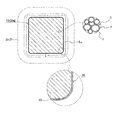
- FIG. 1 is a schematic cross-sectional view of a green compact according to an embodiment.
- FIG. 2 is a schematic perspective view illustrating an example of the electromagnetic component according to the embodiment.
- Patent Document 1 compresses a raw material powder containing a coated iron powder having an insulating coating and a lubricant, heat-treats the obtained compressed product in a nitrogen atmosphere, and then forms a sliding contact surface with a mold in the compressed product. It is disclosed that by performing acid treatment, eddy current loss can be particularly reduced, and iron loss, which is the sum of hysteresis loss and eddy current loss, is small, and a low-loss compacted product can be obtained.
- the heat treatment after compression contributes to the reduction of hysteresis loss, and the use of the coating powder as the raw material powder and the use of a lubricant contributes to the reduction of eddy current loss.
- the metal powder particles are plastically deformed at the time of demolding, so that the conductive portion between the metal powder particles generated on the sliding surface with the mold is immersed in concentrated hydrochloric acid. If divided, eddy current loss can be further reduced, and iron loss can be reduced.
- acid treatment is required, the number of steps is large, and improvement in manufacturability is desired. Further, if the acid treatment is performed only on a specific portion of the compressed product so as not to damage the sound insulation coating, the number of steps is further increased if a masking treatment or the like is performed before the acid treatment. If the acid treatment is omitted, a sufficient reduction in eddy current loss cannot be expected as shown in a test example described later.
- the heat treatment after compression is performed in a nitrogen atmosphere as shown in a test example described later.
- eddy current loss can be reduced as compared with a case where acid treatment is not performed after heat treatment (hereinafter, sometimes referred to as only nitrogen treatment).
- the iron loss in the case of air treatment is the case where acid treatment is performed after heat treatment in a nitrogen atmosphere (hereinafter, the case where nitrogen treatment and acid treatment are used together may be referred to as nitrogen treatment + acid treatment). Greater than iron loss. Therefore, the iron loss is small without performing acid treatment after the heat treatment to the above-mentioned compressed material.
- the iron loss is smaller than the case of only nitrogen treatment, preferably the iron loss is smaller than the case of atmospheric treatment. More preferably, a green compact with the same degree as that in the case of nitrogen treatment + acid treatment and further lower iron loss is desired.
- the green compact according to the present disclosure is a green compact in which a plurality of coated soft magnetic particles each including iron-based particles and an insulating coating covering the surface of the iron-based particles are assembled.
- An iron-based oxide film having a cross-sectional peripheral length of a magnetic path cross section when the powder compact is used as a magnetic core is greater than 20 mm, and at least part of the surface of the powder compact has an average thickness of 0.5 ⁇ m to 10.0 ⁇ m. Covered with.
- the ratio of the surface area to the volume of the green compact is surface area / volume, and the green compact is 100% by volume.
- the content of Fe 3 O 4 present in the iron-based oxide film is as follows (1) to (3) Satisfy any one of the following.
- the iron loss is smaller than that in the case of only the above nitrogen treatment, preferably smaller than that in the case of atmospheric treatment, for the following reason. More preferably, it is possible to construct a magnetic core with the same degree as in the case of nitrogen treatment + acid treatment, and further with a lower iron loss and a low loss.
- the above-mentioned compacting body can be manufactured by, for example, compressing a raw material powder mainly composed of a coating powder having an insulating coating on the surface of iron-based particles, and then subjecting the compact to a heat treatment under specific conditions (described later). (Refer to the manufacturing method of the green compact). Therefore, the above green compact can omit the acid treatment after the heat treatment and is excellent in manufacturability.
- the eddy current loss can be reduced
- the above-mentioned green compact has a size in which the cross-sectional circumference of the magnetic path cross section is larger than 20 mm and a relatively long eddy current loop corresponding to the cross-sectional circumference is easily formed. I can say that. It can be said that the above compacted compact tends to have large eddy current loss due to its size.
- the iron base particles are electrically insulated mainly by the insulating coating. Further, the iron base particles constituting at least a part of the surface of the green compact, particularly at least a part of the sliding contact surface with the mold where the conductive portion is likely to occur at the time of demolding, are made of iron base particles.
- the above-mentioned green compact has improved surface insulation by the insulating coating and the iron-based oxide film.
- the above-mentioned green compact has a sufficiently higher specific resistance than iron-based particles, the content of Fe 3 O 4 having a lower specific resistance as an insulating material is small, and is specified according to the surface area / volume. Meet the range.
- the above-mentioned green compact is more Fe 3 O 4 than in the case of the above-mentioned air treatment.
- the amount of Fe 3 O 4 is preferably smaller than that of the above-described nitrogen treatment + acid treatment. Therefore, the above-mentioned green compact can reduce eddy current loss.
- the increase in hysteresis loss can be suppressed, preferably the hysteresis loss can be reduced.
- the above-mentioned green compact is made of Fe 3 O 4 which is a ferromagnetic body and has a larger coercive force than pure iron in the iron-based oxide film. In the case where it is included, the content is in a specific range and tends to be smaller than that in the case of the air atmosphere. Therefore, the above-mentioned green compact can suppress an increase in hysteresis loss due to the inclusion of Fe 3 O 4 , and the hysteresis loss can be made equal to or less than that in the case of atmospheric treatment.
- the above green compact since a small amount of Fe 3 O 4 as the surface area / volume is small, the increase in hysteresis loss due to Fe 3 O 4 are present in excess on the surface of the green compact Hard to invite.
- the cross-sectional circumference is 40 mm or more and the surface area / volume is 0.60 mm ⁇ 1 or less.
- the above-mentioned form has a size in which the eddy current loop is likely to become longer according to the cross-sectional peripheral length, the insulating coating and the iron-based oxide film are excellent in insulation as described above, and a specific amount of Fe 3 O 4 is present. Therefore, a low-loss magnetic core can be constructed.
- the entire surface of the compacted body is covered with an iron-based oxide film, and the thickness of an arbitrary portion of the iron-based oxide film is 0.5 ⁇ m or more and 10.0 ⁇ m or less.
- an iron-based oxide film As an example of the above compacted body, the entire surface of the compacted body is covered with an iron-based oxide film, and the thickness of an arbitrary portion of the iron-based oxide film is 0.5 ⁇ m or more and 10.0 ⁇ m or less.
- One form is mentioned.
- the above-mentioned form has a small variation in the thickness of the iron-based oxide film, is uniformly present on the surface of the green compact, and the iron-based oxide film between the iron-based particles constituting the surface of the green compact is good It can be said that it can be insulated. Therefore, the above form has a higher surface insulation, makes it easier to reduce eddy current loss, and can suppress an increase in hysteresis loss due to the presence of locally thick portions, thus constructing a magnetic core with lower loss. it can. Moreover, the said form does not require the masking process for forming an iron-type oxide film only in a specific location, and is more excellent in productivity.
- the relative density of the compacted body is 90.0% or more and 99.0% or less.
- the compression of the manufacturing process is also high density, iron-based oxide film is hardly formed excessively, the Fe 3 O 4 can be contained properly during heat treatment.
- the above-mentioned form is not too high in density, it is not necessary to make the molding pressure very high during the manufacturing process, it is easy to prevent damage to the insulation coating due to excessive molding pressure, and a sound insulation coating is provided. Can do. Therefore, the said form can construct
- the electromagnetic component of the present disclosure includes a coil and a magnetic core on which the coil is disposed, and includes the powder compact according to any one of the above in at least a part of the magnetic core.
- the above-mentioned electromagnetic component has a low loss because at least a part, preferably all, of the magnetic core is composed of the above compacted body. Moreover, since said compacting body is excellent in manufacturability, said electromagnetic component is also excellent in manufacturability.
- the manufacturing method of the compacting body concerning this indication is provided with the following forming processes and a heat treatment process.
- (Molding step) A step of compressing raw material powder including iron-based particles and an insulating coating covering the surfaces of the iron-based particles and a lubricant to form a compressed product.
- (Heat treatment step) A step of subjecting the compressed product to a heat treatment to form a green compact having a cross-sectional circumference of a magnetic path cross section larger than 20 mm when used for a magnetic core.
- Lubricants include those whose decomposition start temperature is 170 ° C. or higher, and the content of the lubricant is 0.10% by mass or more and 0.60% by mass or less with the mass of the raw material powder being 100%.
- the heat treatment conditions are such that the oxygen concentration in the atmosphere is 0.01 vol% or more and 5.0 vol% or less, and the temperature is higher than 520 ° C and 700 ° C or lower.
- a green compact capable of constructing a low-loss magnetic core is obtained for the following reason. And according to the manufacturing method of said compacting body, said low-loss compacting body can be manufactured, without performing post-processing, such as an acid treatment, after heat processing.
- an iron-based oxide is generated by the combination of Fe in the iron-based particles constituting the compact and oxygen in the atmosphere,
- a compacting body in which at least a part of the surface of the compressed product is covered with an iron-based oxide film can be produced.
- This iron-based oxide film is an iron-based particle that constitutes at least a part of the surface of the compressed material where the insulating coating peels off and the iron-based particles are exposed, typically the surface of the compressed material in contact with the mold.
- the iron base particles are insulated from each other through the interposition.
- FIG. 1 is a cross-sectional view taken along the line (I)-(I) (the plane perpendicular to the magnetic flux) shown in FIG.
- the green compact 10 is a compact mainly composed of soft magnetic powder, and is manufactured by compressing a raw material powder mainly composed of soft magnetic powder into a predetermined shape, followed by heat treatment.
- the green compact 10 is used for at least a part of the magnetic core 3 provided in the electromagnetic component 1 as shown in FIG. 2 to form a magnetic path.
- FIG. 2 illustrates a case where a plurality of powder compacts 10 (core pieces 31m, 32) are combined to form an annular closed magnetic circuit.
- the green compact 10 has various shapes (see the section of electromagnetic parts described later).
- the green compact 10 is a collection of a plurality of coated soft magnetic particles each including iron-based particles 7 and an insulating coating 8 that covers the surface of the iron-based particles 7.
- the cross-sectional circumferential length L of the magnetic path cross section S 10 (hatched surface in FIG. 1) is relatively long.
- the compacting body 10 of embodiment is provided with the iron-type oxide film 13 of specific thickness as a coating layer which covers at least one part of the surface.
- the iron-based oxide film 13 has a specific component (Fe 3 O 4 ) content within a specific range.
- the green compact 10 has a specific size such that the cross-sectional circumferential length L is relatively long, the powder compact 10 includes an insulating coating and an iron-based oxide film 13 and has a low loss magnetic core 3 due to a small amount of Fe 3 O 4. Can be built.
- the green compact 10 will be described in more detail.
- the iron-based particles 7 constituting the coated soft magnetic particles 9 are made of an iron-based material mainly composed of Fe.
- the iron-based material include pure iron (purity 99% by mass or more, the balance being inevitable impurities), and an iron-based alloy containing more than 50% by mass of Fe.
- the iron-based alloy include an Fe—Si—Al alloy, an Fe—Si alloy, and an Fe—Al alloy.
- pure iron is preferable in that it has a high magnetic permeability and magnetic flux density, is excellent in plastic deformability, can easily increase the density and strength of the green compact 10, and can be reduced in hysteresis loss if it is high purity.
- the insulating coating 8 constituting the coated soft magnetic particles 9 is interposed between the iron-based particles 7 to increase the insulation and contribute to the reduction of eddy current loss.
- Examples of the insulating material constituting the insulating coating 8 include the following.
- the insulating coating 8 may be either a single layer structure or a multilayer structure composed of a plurality of different insulating materials.
- Metal salt compounds Metal phosphate compounds (typically iron phosphate, manganese phosphate, zinc phosphate, calcium phosphate, etc.), metal borate compounds, metal silicate compounds, metal titanate compounds (4) Resin: Polyamide resin (nylon 6, nylon 66, etc.), silicone resin, etc. (5) Higher fatty acid salt Phosphate metal salt compounds such as iron phosphate have excellent adhesion to iron. To have excellent deformability, hardly damaged and deformed following the deformation of the iron-based particles 7 at the time of molding. Therefore, the green compact 10 has a sound insulation coating 8 and can easily reduce eddy currents.
- the average thickness of the insulating coating 8 is, for example, 10 nm or more and 1 ⁇ m or less. If the average thickness is 10 nm or more, the iron base particles 7 can be well insulated. If the average thickness is 1 ⁇ m or less, there are not too many insulating coatings 8, and it is possible to suppress a decrease in the ratio of the magnetic component in the green compact 10 due to excessive insulation coatings 8 and to have desired magnetic properties. it can.
- the lower limit of the thickness (the total thickness in the case of a multilayer structure) can be 20 nm or more, 50 nm or more, and further greater than 100 nm, and the upper limit can be 500 nm or less, 300 nm or less, and further 250 nm or less. .
- the average thickness depends on the thickness of the insulating coating 88 of the coating powder used for the raw material and tends to be substantially equal. Therefore, the thickness of the insulating coating 8 may be adjusted to a desired value at the raw material stage.
- the specification [0041] of Patent Document 1 can be referred to.
- the average particle diameter of the covering soft magnetic particle 9 which comprises the compacting body 10 50 micrometers or more and 400 micrometers or less are mentioned, for example. If the average particle size is 50 ⁇ m or more, it is easy to obtain a high-density powder compact 10, and if it is 400 ⁇ m or less, it is easy to reduce eddy current loss and to provide a compact core 10 capable of constructing a low-loss magnetic core 3. be able to.
- the average particle diameter can be 50 ⁇ m or more and 150 ⁇ m or less, 50 ⁇ m or more and less than 100 ⁇ m, and further 50 ⁇ m or more and 80 ⁇ m or less.
- the average particle size depends on the size of the coating powder used for the raw material and tends to be substantially equal, the average particle size may be adjusted to a desired value in the raw material stage.
- a cross-section of the green compact 10 is taken, and each particle is extracted by analyzing the observation image of the cross-sectional scanning electron microscope with commercially available image analysis software.
- the diameter of the equivalent area circle is defined as the particle diameter, and an average of 1,000 or more particle diameters is taken.
- the green compact 10 is mainly composed of the above-mentioned coated soft magnetic particles 9 (90% by mass or more with the green compact 10 as 100%).
- the lubricants and additives used at the time of molding, those modified by heat treatment, and the inclusion of pores are allowed.
- the cross-sectional circumferential length L is the length of the contour line surrounding the cross section when the powder compact 10 is used in the magnetic core 3 and cut in a plane perpendicular to the magnetic flux, and is parallel to the magnetic flux in the powder compact 10. It is equal to the circumference of the outer peripheral surface to be arranged.
- the rectangular parallelepiped green compact 10 as shown in FIG. 2 (core pieces 31m), for the magnetic path cross section S 10 is rectangular (Fig. 1), the cross-sectional circumferential length L contour line of the rectangle Equal to the total length of
- the iron-based particles 7 constituting the surface arranged in parallel with the magnetic flux in the magnetic core 3 are in contact with each other and are in a conductive state, an eddy current loop corresponding to the cross-sectional circumferential length L is formed, and eddy current loss occurs. Tends to be large. Although it can be said that the green compact 10 having a relatively long cross-sectional peripheral length L tends to have large eddy current loss when attention is paid to its size, it is composed of the coated soft magnetic particles 9 and has a specific iron type as described above. Since a specific amount of the oxide film 13 is provided, eddy current loss can be reduced.
- the green compact 10 has a cross-sectional circumference L of 45 mm or more, 50 mm or more, and 100 mm or more as shown in a test example described later, the effect of reducing eddy current loss is more easily obtained.
- the upper limit of the cross-sectional circumferential length L is, for example, 300 mm or less, 250 mm or less, and further 200 mm or less from the viewpoint of manufacturing the green compact 10.
- One feature of the green compact 10 is that it includes an iron-based oxide film 13 that covers at least part of its surface.
- the iron-based oxide constituting the iron-based oxide film 13 is more excellent in electrical insulation than the iron-based particles 7.
- Such an iron-based oxide is present on the surface of the green compact 10 to enhance the insulation of the surface.
- the iron-based oxide is interposed between the iron-based particles 7 to enhance the insulation between the iron-based particles 7, and can block the eddy current path across the iron-based particles 7.
- the existence region of the iron-based oxide film 13 is an outer peripheral surface arranged parallel to the magnetic flux when used in the magnetic core 3 among the surfaces of the powder compact 10. It is preferable to include at least a part. In particular, it is preferable to provide an eddy current loop along the circumferential direction of the outer peripheral surface.
- the powder compact 10 having a rectangular parallelepiped shape shown in FIG. 2 includes an iron-based oxide film 13 extending from one end surface arranged orthogonal to the magnetic flux to the other end surface facing the one end surface. .
- an eddy current loop that can be generated on the surface of the green compact 10 can be shortened. Specifically, the length of the eddy current loop can be made less than the circumferential length L of the cross section, and eddy current loss can be reduced.
- the iron-based oxide film 13 covering substantially the entire outer peripheral surface is provided, the eddy current flowing through the outer peripheral surface can be sufficiently reduced, and the eddy current loss can be further reduced.
- the iron-based oxide film 13 covering substantially the entire surface of the green compact 10 is provided, the eddy current flowing on the surface of the green compact 10 can be reduced more effectively, and the eddy current loss can be further reduced. In this case, the productivity is excellent as described later.
- the iron-based oxide film 13 is Fe 3 O 4 (triiron tetroxide, magnetite) depending on the surface / volume of the green compact 10 when the ratio of the surface area to the volume of the green compact 10 is surface area / volume. ) Content is in a specific range.
- Fe 3 O 4 has a larger specific resistance than the iron-based particles 7, and interstitial between the iron-based particles 7 can enhance the insulation between the iron-based particles 7 and reduce eddy current loss.
- Fe 3 O 4 has a relatively low specific resistance as an insulating material, and if it contains a large amount of Fe 3 O 4 , it causes an increase in eddy current loss.
- Fe 3 O 4 which is a ferromagnetic material and has a coercive force larger than that of pure iron causes an increase in hysteresis loss.
- including Fe 3 O 4 can lead to an increase in iron loss.
- an increase in eddy current loss and hysteresis loss due to the inclusion of Fe 3 O 4 It was found that eddy current loss and hysteresis loss may be reduced depending on the content. Further, it was found that the smaller the surface area / volume, the more easily the eddy current loss is affected by the amount of Fe 3 O 4 .
- the content of Fe 3 O 4 in the green compact 10 is specified as follows according to the surface area / volume.
- the content of Fe 3 O 4 below is a ratio when the volume of the green compact 10 is 100%. (1) When the surface area / volume is 0.40 mm ⁇ 1 or less, less than 0.085% by volume (2) When the surface area / volume is larger than 0.40 mm ⁇ 1 and 0.60 mm ⁇ 1 or less, 0.12% by volume (3) 0.15% by volume or less when the surface area / volume is larger than 0.60 mm ⁇ 1
- the green compact 10 has a specific range even when Fe 3 O 4 is contained in the iron-based oxide film 13, so eddy current loss , And an increase in hysteresis loss can be suppressed, and a low-loss magnetic core 3 can be constructed.
- the hysteresis loss tends to increase as the content of Fe 3 O 4 increases, and the eddy current loss tends to increase as the content increases to some extent. Therefore, Fe 3 O 4 The content of is preferably smaller. Therefore, in any of the cases (1) to (3), the content of Fe 3 O 4 is 0% by volume.
- the green compact 10 of the above (1) and (2) having a cross-sectional peripheral length L of 40 mm or more and a surface area / volume of 0.60 mm ⁇ 1 or less has a longer cross-sectional peripheral length L, so Therefore, as the insulating material, it is preferable that the content of Fe 3 O 4 having a relatively small specific resistance is smaller and the thickness of the iron-based oxide film 13 is thinner.
- the iron-based oxide film 13 has a form substantially composed of Fe 3 O 4 and iron oxide other than Fe 3 O 4 , for example, ⁇ -Fe 2 O 3 , ⁇ -Fe 2 O 3 , FeO, insulating coating Examples include an oxide containing 8 constituent elements such as Fe 2 SiO 4 and Fe 2 PO 5 . From the viewpoint of reducing the iron loss, it is preferable that the content of Fe 3 O 4 is low and further not included. On the other hand, when Fe 3 O 4 is contained in the above range, an improvement in strength and an improvement in corrosion resistance can be expected, and a compact 10 having high strength and excellent corrosion resistance can be obtained. From these, the total content of iron oxides other than Fe 3 O 4 is 0% by mass or more and 100% by mass or less, and further 95% by mass or less, with the iron-based oxide film 13 being 100% by mass.
- the average thickness thereof is not less than 0.5 ⁇ m and not more than 10.0 ⁇ m. If the average thickness is 0.5 ⁇ m or more, the iron-based oxide film 13 excellent in insulation as described above is sufficiently present, and the effect of reducing the eddy current loss due to the provision of the iron-based oxide film 13 is good. can get. Since the effect of reducing eddy current loss is more easily obtained as the average thickness increases, the average thickness can be 0.6 ⁇ m or more, 0.7 ⁇ m or more, and further 1.0 ⁇ m or more.
- the average thickness is 10.0 ⁇ m or less, the content of Fe 3 O 4 tends to be small, and the effect of suppressing the increase in hysteresis loss and eddy current loss due to excessive Fe 3 O 4 content can be obtained satisfactorily.
- the thickness of an arbitrary portion in the iron-based oxide film 13 is 0.5 ⁇ m or more and 10.0 ⁇ m or less, the thickness variation is small, and the iron-based oxide film having a uniform thickness on the surface of the green compact 10. Therefore, the effect of reducing the eddy current loss due to the iron-based oxide film 13 and the effect of suppressing the increase in hysteresis loss due to excessive Fe 3 O 4 content can be obtained.
- the iron-based oxide film 13 has a small thickness variation as described above. This thickness can be 0.55 ⁇ m or more and 9.0 ⁇ m or less, and 0.6 ⁇ m or more and 8.0 ⁇ m or less.
- the relative density of the green compact 10 is 90.0% or more, the green compact 10 sufficiently contains the iron-based particles 7 and is dense and dense, and also has excellent magnetic properties.
- the compact in the manufacturing process can be said to have a high density, and a compacted molded body 10 capable of constructing a low-loss magnetic core 3 with the iron-based oxide film 13 while suppressing excessive formation of Fe 3 O 4 is provided. it can.
- the green compact 10 can be provided with a sound insulating coating 8 and excellent in insulating properties. From the viewpoint of preventing damage to the insulating coating 8, the relative density can be 98.5% or less, 98.0% or less, and further 97.5% or less.
- the compacting body 10 can construct a low-loss magnetic core 3. Moreover, since it can manufacture without performing acid treatment after heat processing by performing specific heat processing in a manufacture process, the compacting body 10 is excellent also in manufacturability. These effects will be specifically described in test examples to be described later.
- the electromagnetic component 1 includes a coil 2 formed by winding a winding 2w and a magnetic core 3 on which the coil 2 is disposed.
- the electromagnetic component 1 according to the embodiment includes the green compact 10 according to the embodiment on at least a part of the magnetic core 3.
- Examples of the electromagnetic component 1 include a reactor, a transformer, a motor, a choke coil, an antenna, a fuel injector, and an ignition coil.
- wire which equips the outer periphery of a conductor with an insulating layer
- the conductor include a wire such as a round wire and a flat wire made of a conductive material such as copper, copper alloy, aluminum, and aluminum alloy.
- the constituent material of the insulating layer include enamel, tetrafluoroethylene-hexafluoropropylene copolymer (FEP) resin, polytetrafluoroethylene (PTFE) resin, and silicone rubber.
- FEP tetrafluoroethylene-hexafluoropropylene copolymer
- PTFE polytetrafluoroethylene
- the electromagnetic component 1 in FIG. 2 includes a coil 2 having a pair of cylindrical winding portions 2a and 2b connected by a connecting portion 2r, and a pair of inner core portions 31 and 31 in which the winding portions 2a and 2b are arranged.
- positioned but protrudes from the coil 2 is illustrated.
- Each inner core portion 31 is arranged between a plurality of rectangular parallelepiped core pieces 31m mainly composed of a soft magnetic material, and adjacent core pieces 31m, 31m, and has a flat gap smaller in relative permeability than the core pieces 31m. Material 31g.
- the outer core portion 32 is a columnar core piece mainly composed of a soft magnetic material. Among the plurality of core pieces 31 m and 32, at least one core piece is constituted by the green compact 10. In the magnetic core 3 of this example, all the core pieces are composed of the green compact 10 and have a low loss. As a result, the electromagnetic component 1 (reactor in this example) also has a low loss.
- the magnetic core 3 has an integral form composed of only one core piece.
- the shape of each core piece in the combined form include an E shape, an I shape (bar shape), a T shape, and a [shape].
- an integrally formed annular body, C-shaped body, and the like can be given.
- all core pieces are composed of the green compact 10 (this example), core pieces other than the green compact 10, such as laminated cores of electromagnetic steel sheets, soft magnetic powder, It can be set as the form containing the core etc. of the composite material containing resin. In addition, it can be set as a form provided with an air gap instead of the gap material 31g, a form not provided with a magnetic gap in the above-described integrated form, and the like.
- the manufacturing method of the compacting body which concerns on embodiment is equipped with the shaping
- a specific size powder is manufactured using a specific raw material powder, heat treatment is performed under specific conditions, and acid treatment or the like is not performed after the heat treatment. Therefore, according to the manufacturing method of the compacting body of embodiment, the compacting body which can build a low-loss magnetic core can be manufactured, although there are few processes and it is excellent in manufacturability.
- each process will be described in detail.
- the prepared raw material powder is supplied to a mold having a predetermined shape, compressed, and demolded to obtain a compressed product.
- the raw material powder includes a coated soft magnetic powder comprising iron-based particles 7 made of the iron-based material described in the above-mentioned iron-based particles 7 and an insulating coating 8 that covers the surfaces of the iron-based particles 7, lubrication
- One of the features is to use an agent containing an agent.
- the coated soft magnetic powder can be obtained by forming the insulating coating 8 on the surface of the iron-based particles 7 using the insulating material described in the section of the insulating coating 8 described above. Known methods can be used to manufacture the iron-based particles 7 (iron-based powder) and to form the insulating coating 8. Commercially available coating powder can also be used.
- the constituent material of the insulating coating 8 provided in the green compact 10 after the heat treatment may be different because the insulating coating 8 at the raw material stage is modified during the heat treatment.
- the material of the insulating coating 8 at the raw material stage may be selected so that the constituent material of the insulating coating 8 after the heat treatment becomes a desired material.
- lubricant By including a lubricant in the raw material powder, it is possible to reduce damage to the insulating coating 8 by reducing friction between the coated powder particles at the time of molding and the like, and reducing friction between the coated powder particles and the mold at the time of demolding. .
- a lubricant having a decomposition start temperature in the atmosphere of 170 ° C. or higher it is easy to prevent excessive oxidation of the compressed product during the heat treatment, and the green compact is provided with the iron-based oxide film 13 containing a specific amount of Fe 3 O 4. It is easy to obtain the molded body 10.
- Such lubricants include ethylene bis-stearic acid amide, stearic acid amide, oleic acid amide, palmitic acid amide, behenic acid amide, erucic acid amide, zinc stearate, lithium stearate, calcium stearate, magnesium stearate, stearic acid Examples thereof include sodium and aluminum stearate.
- Lubricants other than those listed above, for example, metal soaps, fatty acid amides, higher fatty acid amides, inorganic substances, fatty acid metal salts and the like can be included. Note that the decomposition start temperature of the lubricant may vary depending on the atmosphere during the heat treatment.
- the atmosphere at the time of heat processing is performed in the specific low oxygen atmosphere whose oxygen concentration is lower than air (details are mentioned later). Since the decomposition start temperature in the atmosphere tends to be lower than the decomposition start temperature in a low-oxygen atmosphere, the decomposition start temperature in the atmosphere is used here.
- the total content of the lubricant including the lubricant having a decomposition start temperature of 170 ° C. or higher is set to 0.10% by mass or more and 0.60% by mass or less with the mass of the raw material powder being 100%. If the total content is 0.10% by mass or more, the above-described damage prevention effect of the insulating coating 8 due to the inclusion of the lubricant in the raw material powder can be obtained satisfactorily. Since the damage prevention effect of the insulating coating 8 is easily obtained as the total content increases, the total content is set to 0.15% by mass or more, 0.20% by mass or more, and further 0.30% by mass or more. be able to.
- the total content is 0.60% by mass or less, it is possible to reduce a decrease in density, a decrease in the proportion of magnetic components, an increase in removal time, etc. due to excessive inclusion of a lubricant, and a high-density compressed product with high productivity. Easy to get. If the total content is 0.55% by mass or less, 0.50% by mass or less, and further 0.45% by mass or less, the above-described insulating coating 8 can be satisfactorily prevented and the magnetic component can be added at a high density. It is easy to obtain a compact containing sufficient. Moreover, it is easy to suppress the above-mentioned progress of internal oxidation by making the said total content into the above-mentioned specific range.
- the shape and size of the cavity of the mold may be selected so that a compressed product having a desired shape (a green compact 10 after heat treatment) can be obtained.
- cross-sectional circumferential length L of the magnetic path cross section S 10 in the case of using the magnetic core 3 is molded 20mm greater compression product (green compact 10).
- the molding pressure can be appropriately selected according to the shape, size, density, and the like of the compressed product, and examples thereof include about 300 MPa to 2000 MPa.
- the molding pressure can be 400 MPa or more and 1800 MPa or less, and further 500 MPa or more and 1700 MPa or less.
- the raw material powder is mixed and the lubricant is uniformly dispersed.
- a lubricant can be applied to a portion of the mold that comes into contact with the raw material powder or the compressed material.
- the atmosphere at the time of molding includes an air atmosphere.
- the mold temperature at the time of molding includes normal temperature (for example, about 20 ° C.). Since the mold temperature can be increased by the processing heat, it may be appropriately adjusted.
- the Fe 3 O 4 content contained in the iron-based oxide film is in a specific range and the iron-based oxide film has a specific thickness (see the above-mentioned section of the green compact).
- One of the characteristics is to satisfy the above condition.
- the heat treatment is performed in such a manner that the atmosphere is a low oxygen atmosphere having an oxygen concentration of 0.01% by volume to 5.0% by volume, and the heating temperature is higher than 520 ° C. and 700 ° C. or lower.
- the formation region of the iron-based oxide film includes a conductive portion in which the iron base particles 7 are plastically deformed and exposed from the insulating coating 8 at the time of demolding, and the iron base particles 7 are in contact with each other. It is preferable. At the conduction point, Fe contained in the iron-based particles 7 and oxygen in the atmosphere are easily in contact with each other, and both are easily bonded to form an iron-based oxide film. This is because the formation of this iron-based oxide film can insulate the iron-based particles 7 and contribute to the reduction of eddy current loss.
- a masking process or the like can be performed in advance on a portion where the iron-based oxide film is not formed on the surface of the compressed product. In the case where an iron-based oxide film is formed on the entire surface of the compressed product, the above masking treatment is not necessary, and the productivity is excellent.
- coated soft magnetic particles 9 having a sound insulating coating 8 on the surface of the compressed material also exist. Since oxygen in the atmosphere can permeate the insulating coating 8, iron-based oxide films can be formed above and below the healthy insulating coating 8. In addition, since the iron-based oxide film can be formed on the coated soft magnetic particles 9 constituting the inside of the compressed material by using the gap formed by removing the lubricant as described above, excessive internal oxidation is performed. A specific heat treatment condition is set so as to suppress it.
- the oxygen concentration in the atmosphere is set to 0.01% by volume or more with the entire atmosphere as 100%, an iron-based oxide film having a specific content of Fe 3 O 4 can be formed.
- the higher the oxygen concentration the easier it is to produce Fe 3 O 4 , but it is easier to thicken the iron-based oxide film, and it is possible to manufacture the green compact 10 having an iron-based oxide film and excellent insulation. Therefore, the oxygen concentration can be 0.015% by volume or more, and further 0.02% by volume or more.
- the oxygen concentration is 5.0% by volume or less, excessive formation of Fe 3 O 4 and an iron-based oxide film can be suppressed, and the green compact 10 appropriately including an iron-based oxide film can be manufactured.
- the oxygen concentration may be made smaller as described above. It is preferable to adjust the oxygen concentration of the atmosphere to a desired amount within the specific range described above.
- This heat treatment can be performed using either a continuous process in which a target object (here, a compressed product) is continuously heat-treated or a batch process in which a predetermined amount of a target object is heat-treated at once.
- Continuous processing is suitable for industrial mass production.
- the batch processing can be performed with high accuracy in the atmosphere, and is therefore suitable when the above-described oxygen concentration is further lowered and further loss reduction is desired.
- a raw material powder in which a coated soft magnetic powder (coated powder) having the following two layers of insulating coating 8 and a lubricant are mixed is used.
- the coating powder is prepared as follows. A pure iron powder composed of pure iron (99% by mass or more of Fe, the remainder inevitable impurities) and having an average particle size of 53 ⁇ m was prepared. The average particle diameter is a 50% particle diameter (mass) measured using a commercially available laser diffraction / scattering particle diameter / particle size distribution measuring apparatus.
- an inner layer composed of iron phosphate on the surface of pure iron powder particles (iron-based particles 7) by bondage treatment
- Si and O (oxygen) as main components are formed on the inner layer by chemical conversion treatment.
- An outer layer is formed.
- the lubricant ethylenebisstearic acid amide having a decomposition start temperature in the air of 215 ° C. was prepared. Tables 1 to 4 show the lubricant content (% by mass) when the mass of the raw material powder is 100%.
- a plurality of columnar compacts such as a rectangular parallelepiped shape are prepared for each sample, heat treated to form a compacted body (core piece), and these compacted bodies are assembled in an annular shape.
- a magnetic core (see magnetic core 3 in FIG. 2) is constructed.
- the ratio of the surface area to the volume “surface area / volume (mm ⁇ 1 )” and the magnetic core of the powder compact forming the portion where the coil is arranged inner core portion 31 in the magnetic core 3 of FIG. 2).
- the mold is selected and molded so that the cross-sectional peripheral length (mm) of the magnetic path cross section when used in the above is the size shown in Tables 1 to 4.
- the surface area / volume is varied by changing the length of each side of the rectangular parallelepiped forming the green compact.
- the molding pressure is selected from the range of 700 MPa to 1500 MPa, and the density of the green compact is varied. Among the above ranges, the larger the molding pressure, the higher the density of the green compact.
- a compacted body having a relative density of 92.6% can be obtained by setting 981 MPa ( ⁇ 9 ton / cm 2 ).
- all samples are molded in an air atmosphere, and the mold temperature is set to room temperature.
- the heat-treated products are subjected to heat treatment at the atmospheres and temperatures shown in Tables 1 to 4.
- the rate of temperature rise to the heat treatment temperature is 5 ° C./min, and the heat treatment time is 15 minutes.
- the atmosphere was a nitrogen atmosphere (atmosphere substantially free of oxygen, oxygen concentration: less than 0.001% by volume), air atmosphere (oxygen concentration: about 21% by volume), and low oxygen atmosphere (oxygen concentration: Table 1).
- a compacted body in which a plurality of coated soft magnetic particles 9 including the iron-based particles 7 and the insulating coating 8 are aggregated is obtained for each sample.
- the atmosphere of the heat treatment is an air atmosphere or a low oxygen atmosphere
- the entire surface of the green compact is covered with a coating layer (here, an iron-based oxide film).
- the samples after heat treatment (hereinafter referred to as heat-treated materials) are subjected to acid treatment under the following conditions.
- the acid treatment is performed on the sliding contact surface with the mold among the surfaces of the compressed material before the heat treatment.
- a sample that has been heat-treated in an air atmosphere or a low-oxygen atmosphere is not acid-treated.
- a portion (sliding surface) of the surface of the heat treatment material is immersed for 20 minutes in a liquid tank containing concentrated hydrochloric acid having a pH of 1 and a temperature of 26 ° C. while stirring the concentrated hydrochloric acid.
- the width of the region subjected to the acid treatment in the heat treatment material is 7% with respect to the cross-sectional circumferential length L, and the height of the region subjected to the acid treatment is arranged in parallel to the magnetic flux direction when used in the magnetic core. Same as the height of the surface.
- Masking is performed on the region of the heat treatment material that is not subjected to acid treatment. After the above acid treatment, the object to be treated is washed with water, and then the masking is removed.
- the coating layer other than the insulating coating 8 was used in the sample heat-treated in an air atmosphere or a low oxygen atmosphere. It was confirmed that the In particular, in the surface of the green compact that is in sliding contact with the above-described mold, a coating layer is present at the location where the insulating coating 8 is peeled off and the iron-based particles 7 are exposed in the coated soft magnetic particles 9. It was. There were coating layers above and below the insulating coating 8 at locations other than the sliding contact locations.
- the coating layer was mainly an oxide containing Fe. From this, it is considered that the coating layer was formed by combining Fe of the iron-based particles 7 and oxygen in the atmosphere.
- this coating layer may be referred to as an iron-based oxide film.
- Table 1 shows the thickness ( ⁇ m) of the coating layer (iron-based oxide film) and the volume ratio (volume%) of the coating layer (iron-based oxide film) with respect to the powder-molded body for the obtained powder compacts of each sample.
- Table 4 shows.
- the thickness of the coating layer is obtained by taking a cross-section of the green compact of each sample, observing the cross-section with a laser microscope, selecting any 100 points on the coating layer in the observed image, examining the thickness, and averaging 100 points.
- Tables 1 to 4 Assuming that the coating layer has a uniform thickness over the entire surface of the compacted product, the volume ratio of the coating layer to the compacted product is the above-mentioned average thickness of 100 points as the thickness of the coating layer.
- the volume of the coating layer is determined, and the volume of the coating layer is determined by dividing the volume of the coating layer by the volume of the green compact.
- 10 visual fields were taken, and 10 measurement points were taken for each visual field to obtain 100 points.
- the insulating layer 8 may be included in the coating layer at the measurement point.
- the thickness including the insulating coating 8 is measured as the thickness of the coating layer.
- the relative density (%) was measured for the green compacts of each sample obtained, and the results are shown in Tables 1 to 4.
- the relative density is a value obtained by dividing the actual density of the green compact by the true density.
- the actual density is determined by measuring the volume of the green compact by the Archimedes method and dividing the mass of the green compact by the measured volume.
- the true density is obtained, for example, by using a measuring device such as a pycnometer or by performing component analysis and calculating from the mixing ratio of the constituent components. Alternatively, the true density of the raw material powder can be used.
- Sample No. 2 was subjected to heat treatment in an air atmosphere.
- 1-121 to 1-124 are sample Nos. Above. Although the eddy current loss can be reduced and the iron loss can be reduced as compared with 1-101 (no acid treatment) to 1-104 (no acid treatment), sample no. Eddy current loss tends to be larger than 1-101 (with acid treatment) to 1-104 (with acid treatment), and the iron loss cannot be said to be sufficiently low.
- Sample No. 1-121 to 1-124 are sample Nos. Above. Hysteresis loss tends to be larger than 1-101 to 1-104, and this tendency becomes more prominent as the surface area / volume increases. For these reasons, Sample No. It is conceivable that 1-12-1 to 1-124 have too much Fe 3 O 4 , particularly that the absolute amount of Fe 3 O 4 increases as the surface area / volume increases.
- Sample No. Nos. 1-1 to 1-20 are samples Nos. 1 to 1 that contain Fe 3 O 4 on the surface of the green compact but have been heat-treated in an air atmosphere.
- the eddy current loss is particularly small and the hysteresis loss tends to be smaller than that of 1-121 to 1-124. As a result, the iron loss is small.
- sample no. 1-1 to 1-20 are Sample Nos. It is conceivable that the content of Fe 3 O 4 is smaller than that of 1-121 to 1-124. Specifically, the Fe 3 O 4 content is 0.08% by volume or less (in this example, 0.07% by volume or less) when the surface area / volume is 0.40 mm ⁇ 1 or less, and the surface area / volume is 0.8%. for 0.60 mm -1 or less greater than 40 mm -1, 0.12% by volume or less (more or less 0.10 vol% in the example), if the surface area / volume is greater than 0.60, 0.15 vol% (In this example, it is further 0.14% by volume or less).
- sample No. 1-1 to 1-20 are provided with an iron-based oxide film having better insulation than the iron-based particles 7, thereby improving the insulation between the iron-based particles 7 even if the insulating coating 8 is damaged during the manufacturing process.
- Fe 3 O 4 having a relatively small specific resistance is obtained as Sample No. It may be less than 1-121 to 1-124.
- the resistivity of the iron-based oxide film is the sample No.
- the sample Nos. 1 to 121 to 124 are substantially the same as those in FIGS.
- the thickness of the iron-based oxide film of 1-1 to 1-20 is the same as that of sample no.
- sample No. 1-1 to 1-20 are ferromagnetic materials, and Fe 3 O 4 having a coercive force larger than that of pure iron is designated as Sample No. It may be less than 1-121 to 1-124.
- the surface area / volume is larger than 0.60 mm ⁇ 1 (Sample Nos. 1-16 to 1-20)
- the effect of reducing the hysteresis loss tends to be large.
- Sample No. with large surface area / volume Tends Many absolute amount of Fe 3 O 4 at 1-124, easily a ferromagnetic out greatly influences the coercive force is large Fe 3 O 4, the hysteresis loss is considered large.
- the absolute amount of Fe 3 O 4 is no. Less than 1-124, sample no. There are also samples in which the amount of Fe 3 O 4 of 1-124 is 60% or less, and even less than 40%, and it is considered that the effect of reducing the hysteresis loss is likely to appear.
- the sample No. Nos. 1-16 to 1-20 have a relatively short cross-sectional circumference (here, 40 mm or less). It is thought that the difference in eddy current loss from 1-124 was difficult to occur.
- Sample No. which can construct such a low-loss magnetic core.
- the compacted body of 1-1 to 1-20 can be obtained by compressing a raw material powder containing a coated soft magnetic powder and a specific lubricant, and then subjecting the compressed product to a heat treatment in a specific low oxygen atmosphere.
- the lower the oxygen concentration in the atmosphere in this example, less than 5.0% by volume, further less than 3.0% by volume, especially less than 1.0% by volume), the content of Fe 3 O 4 can be reduced, and the vortex It turns out that it is easy to reduce a current loss.
- the surface area / volume is 0.065% by volume or less, 0.05% by volume or less, further 0.045% by volume or less, particularly 0 .035% by volume or less, if the surface area / volume of greater 0.60 mm -1 or less than 0.40 mm -1, 0.09% by volume or less, further 0.085% by volume or less, particularly 0.07% or less by volume, the surface area
- the / volume is larger than 0.60, it can be said that it is easy to reduce eddy current loss when it is 0.14% by volume or less, further 0.13% by volume or less, particularly 0.12% by volume or less.
- Sample No. 1-1 to 1-20 the sample having a cross-sectional circumference of 40 mm or more and a surface area / volume of 0.6 mm ⁇ 1 or less includes sample No.
- sample Nos. With a cross-sectional circumference of 40 mm or more and a surface area / volume of 0.40 mm ⁇ 1 or less.
- 1-1 to 1-6 and 1-8 to 1-10 are sample Nos. Eddy current loss is sufficiently smaller than that of 1-101 (with acid treatment) and 1-102 (with acid treatment), and iron loss is also small.
- Fe 3 O 4 has a specific amount. It can be said that the effect of reducing the eddy current loss can be sufficiently obtained, and that a lower loss magnetic core equivalent to, preferably lower than, the case where the acid treatment is performed can be constructed without performing the acid treatment after the heat treatment in the nitrogen atmosphere. .
- samples having the same relative density (%) are compared.
- the sample No. 1-21, 1-22 are Sample Nos. Iron loss is smaller than 1-105 (with acid treatment) and 1-106 (with acid treatment).
- 1-23 to 1-25 are sample Nos. Compared with 1-107 (no acid treatment) to 1-109 (no acid treatment), the iron loss is smaller, and the higher the relative density, the smaller the iron loss.
- Nos. 1-21 to 1-24 are sample Nos. 1 and 2 that were heat-treated in an air atmosphere. 1-125 to 1-128 and Sample No.
- the sample No. 1 had a lubricant content of 0.10% by mass or more in the raw material powder.
- 1-26 and 1-27 are Sample Nos. 1-121 and sample no. Iron loss is small compared to 1-101 (with acid treatment, see Table 1). This is because the raw material powder contains a certain amount of lubricant, and the compressed product also contains a certain amount of lubricant, and the lubricant is removed as the temperature rises during heat treatment, but contains a certain amount of lubricant. This is considered to be because the internal oxidation of the compressed product hardly progressed and the excessive content of Fe 3 O 4 could be suppressed.
- the heat treatment temperature is preferably higher than 520 ° C. and not higher than 700 ° C., more preferably higher than 550 ° C. and not higher than 700 ° C.
- Electromagnetic component Coil 2w Winding
Abstract
圧粉成形体であって、圧粉成形体を磁心に用いたときの磁路断面の断面周長が20mmより大きく、圧粉成形体の表面の少なくとも一部は平均厚さ0.5μm以上10.0μm以下の鉄系酸化膜で覆われている。圧粉成形体の体積に対する表面積の割合を表面積/体積とし、圧粉成形体を100体積%として鉄系酸化膜中に存在するFe3O4の含有量が以下の(1)~(3)のいずれか一つを満たす。 (1)表面積/体積が0.40mm-1以下の場合、0.085体積%未満である。 (2)表面積/体積が0.40mm-1より大きく0.60mm-1以下の場合、0.12体積%以下である。 (3)表面積/体積が0.60mm-1より大きい場合、0.15体積%以下である。
Description
本開示は圧粉成形体、電磁部品、及び圧粉成形体の製造方法に関する。本出願は2015年11月10日出願の日本特許出願第2015-220076号に基づく優先権を主張し、前記日本特許出願に記載された全ての内容を援用する。また本出願の一部を構成するものとして特開2012-243912号公報の内容を援用する。
電磁部品などの磁心の一つに、軟磁性粉末が所定の形状に圧縮された圧粉成形体から構成されるものがある(例えば特許文献1)。
本開示にかかる圧粉成形体は、鉄基粒子と、鉄基粒子の表面を覆う絶縁被覆とを備える複数の被覆軟磁性粒子が集合された圧粉成形体である。圧粉成形体を磁心に用いたときの磁路断面の断面周長が20mmより大きく、圧粉成形体の表面の少なくとも一部は平均厚さ0.5μm以上10.0μm以下の鉄系酸化膜で覆われている。圧粉成形体の体積に対する表面積の割合を表面積/体積とし、圧粉成形体を100体積%として鉄系酸化膜中に存在するFe3O4の含有量が以下の(1)~(3)のいずれか一つを満たす。
(1)表面積/体積が0.40mm-1以下の場合、0.085体積%未満である。
(2)表面積/体積が0.40mm-1より大きく0.60mm-1以下の場合、0.12体積%以下である。
(3)表面積/体積が0.60mm-1より大きい場合、0.15体積%以下である。
(1)表面積/体積が0.40mm-1以下の場合、0.085体積%未満である。
(2)表面積/体積が0.40mm-1より大きく0.60mm-1以下の場合、0.12体積%以下である。
(3)表面積/体積が0.60mm-1より大きい場合、0.15体積%以下である。
本開示にかかる圧粉成形体の製造方法は、鉄基粒子と鉄基粒子の表面を覆う絶縁被覆とを備える被覆軟磁性粉末と、潤滑剤とを含む原料粉末を圧縮して、圧縮物を形成する工程と、圧縮物に熱処理を施して、磁心に用いたときの磁路断面の断面周長が20mmより大きい圧粉成形体を形成する工程とを備える。潤滑剤は、分解開始温度が170℃以上であるものを含み、潤滑剤の含有量を、原料粉末を100質量%として0.10質量%以上0.60質量%以下とする。熱処理の条件は、雰囲気の酸素濃度を0.01体積%以上5.0体積%以下とし、温度を520℃より高く700℃以下とする。
特許文献1は、絶縁被覆を有する被覆鉄粉と潤滑剤とを含む原料粉末を圧縮し、得られた圧縮物に窒素雰囲気で熱処理を施した後、圧縮物における金型との摺接面に酸処理を行うことで、特に渦電流損を低減できること、ひいてはヒステリシス損と渦電流損との和である鉄損が小さく、低損失な圧粉成形体が得られることを開示する。圧縮後の熱処理は、ヒステリシス損の低減に寄与し、原料粉末に被覆粉末を用いると共に潤滑剤を用いることは、渦電流損の低減に寄与する。特に、特許文献1に記載されるように、脱型時に金属粉末粒子の塑性変形によって、上述の金型との摺接面に生じる金属粉末粒子間の導通箇所を濃塩酸に浸漬する酸処理によって分断すれば、渦電流損を更に低減でき、鉄損を小さくできる。しかし、熱処理に加えて、酸処理が必要であり、工程数が多く、製造性の向上が望まれる。更に、健全な絶縁被覆を損傷しないように圧縮物の特定の箇所にのみ酸処理を施すために、酸処理前にマスキング処理などを行うと、工程数が更に増える。酸処理を省略すれば、後述する試験例に示すように、渦電流損の十分な低減が望めない。
上述の圧縮後の熱処理を窒素雰囲気ではなく、大気雰囲気とする場合(以下、大気処理の場合と呼ぶことがある)には、後述する試験例に示すように、圧縮後の熱処理を窒素雰囲気とし、かつ熱処理後に酸処理を行わない場合(以下、窒素処理のみの場合と呼ぶことがある)と比較して、渦電流損を低減できる。しかし、大気処理の場合の鉄損は、窒素雰囲気での熱処理後に酸処理を行う場合(以下、窒素処理と酸処理とを併用する場合を窒素処理+酸処理の場合と呼ぶことがある)の鉄損よりも大きい。従って、上述の圧縮物への熱処理後に酸処理などを行うことなく鉄損が小さいこと、詳しくは窒素処理のみの場合よりも鉄損が小さいこと、好ましくは大気処理の場合よりも鉄損が小さいこと、より好ましくは窒素処理+酸処理の場合と同等程度、更には鉄損がより小さい圧粉成形体が望まれる。
本開示にかかる圧粉成形体は、鉄基粒子と、鉄基粒子の表面を覆う絶縁被覆とを備える複数の被覆軟磁性粒子が集合された圧粉成形体である。圧粉成形体を磁心に用いたときの磁路断面の断面周長が20mmより大きく、圧粉成形体の表面の少なくとも一部は平均厚さ0.5μm以上10.0μm以下の鉄系酸化膜で覆われている。圧粉成形体の体積に対する表面積の割合を表面積/体積とし、圧粉成形体を100体積%として鉄系酸化膜中に存在するFe3O4の含有量が以下の(1)~(3)のいずれか一つを満たす。
(1)表面積/体積が0.40mm-1以下の場合、0.085体積%未満である。
(2)表面積/体積が0.40mm-1より大きく0.60mm-1以下の場合、0.12体積%以下である。
(3)表面積/体積が0.60mm-1より大きい場合、0.15体積%以下である。
(1)表面積/体積が0.40mm-1以下の場合、0.085体積%未満である。
(2)表面積/体積が0.40mm-1より大きく0.60mm-1以下の場合、0.12体積%以下である。
(3)表面積/体積が0.60mm-1より大きい場合、0.15体積%以下である。
上記の圧粉成形体は、電磁部品の磁心に用いられた場合に以下の理由によって、上述の窒素処理のみの場合よりも鉄損が小さく、好ましくは大気処理の場合よりも鉄損が小さく、より好ましくは窒素処理+酸処理の場合と同等程度、更には鉄損がより小さく、低損失な磁心を構築できる。かつ、上記の圧粉成形体は、例えば、鉄基粒子の表面に絶縁被覆を備える被覆粉末を主体とする原料粉末を圧縮後、圧縮物に特定の条件で熱処理を施すことで製造できる(後述の圧粉成形体の製造方法参照)。従って、上記の圧粉成形体は、熱処理後の酸処理を省略でき、製造性にも優れる。
(A)渦電流損を低減できる
上記の圧粉成形体は、磁路断面の断面周長が20mmより大きく、断面周長に応じた比較的長い渦電流ループが形成され易い大きさを有するといえる。上記の圧粉成形体は自身の大きさから渦電流損が大きくなり易いものといえる。しかし、上記の圧粉成形体では、鉄基粒子同士が主として絶縁被覆によって電気的に絶縁される。また、上記の圧粉成形体の表面の少なくとも一部、特に上述の脱型時に導通箇所が生じ易い金型との摺接面の少なくとも一部を構成する鉄基粒子同士が、鉄基粒子よりも電気絶縁性に優れる鉄系酸化膜によって電気的に絶縁される。上記の圧粉成形体は、絶縁被覆と鉄系酸化膜とによって表面の絶縁性が高められているといえる。かつ、上記の圧粉成形体は、鉄基粒子よりも比抵抗が十分に高いものの、絶縁材としては比抵抗が低めであるFe3O4の含有量が少なく、表面積/体積に応じて特定の範囲を満たす。後述する試験例に示すように製造条件にもよるが同じ大きさや密度のものを比較すれば、基本的には、上記の圧粉成形体は、上述の大気処理の場合よりもFe3O4が少なく、好ましくは上述の窒素処理+酸処理の場合よりもFe3O4が少ない。従って、上記の圧粉成形体は、渦電流損を低減できる。
上記の圧粉成形体は、磁路断面の断面周長が20mmより大きく、断面周長に応じた比較的長い渦電流ループが形成され易い大きさを有するといえる。上記の圧粉成形体は自身の大きさから渦電流損が大きくなり易いものといえる。しかし、上記の圧粉成形体では、鉄基粒子同士が主として絶縁被覆によって電気的に絶縁される。また、上記の圧粉成形体の表面の少なくとも一部、特に上述の脱型時に導通箇所が生じ易い金型との摺接面の少なくとも一部を構成する鉄基粒子同士が、鉄基粒子よりも電気絶縁性に優れる鉄系酸化膜によって電気的に絶縁される。上記の圧粉成形体は、絶縁被覆と鉄系酸化膜とによって表面の絶縁性が高められているといえる。かつ、上記の圧粉成形体は、鉄基粒子よりも比抵抗が十分に高いものの、絶縁材としては比抵抗が低めであるFe3O4の含有量が少なく、表面積/体積に応じて特定の範囲を満たす。後述する試験例に示すように製造条件にもよるが同じ大きさや密度のものを比較すれば、基本的には、上記の圧粉成形体は、上述の大気処理の場合よりもFe3O4が少なく、好ましくは上述の窒素処理+酸処理の場合よりもFe3O4が少ない。従って、上記の圧粉成形体は、渦電流損を低減できる。
(B)ヒステリシス損の増大を抑制できる、好ましくはヒステリシス損を低減できる
上記の圧粉成形体は、強磁性体であって純鉄よりも保磁力が大きいFe3O4を鉄系酸化膜中に含む場合にも、その含有量が特定の範囲であり、大気雰囲気の場合よりも少ない傾向にある。そのため、上記の圧粉成形体は、Fe3O4の含有によるヒステリシス損の増大を抑制でき、ヒステリシス損を大気処理の場合と同等程度以下にできる。特に、上記の圧粉成形体は、表面積/体積が小さいほどFe3O4の含有量が少ないため、圧粉成形体の表面にFe3O4が過剰に存在することによるヒステリシス損の増大を招き難い。
上記の圧粉成形体は、強磁性体であって純鉄よりも保磁力が大きいFe3O4を鉄系酸化膜中に含む場合にも、その含有量が特定の範囲であり、大気雰囲気の場合よりも少ない傾向にある。そのため、上記の圧粉成形体は、Fe3O4の含有によるヒステリシス損の増大を抑制でき、ヒステリシス損を大気処理の場合と同等程度以下にできる。特に、上記の圧粉成形体は、表面積/体積が小さいほどFe3O4の含有量が少ないため、圧粉成形体の表面にFe3O4が過剰に存在することによるヒステリシス損の増大を招き難い。
上記の圧粉成形体の一例として、断面周長が40mm以上、表面積/体積が0.60mm-1以下である形態が挙げられる。
上記形態は、断面周長に応じて渦電流ループがより長くなり易い大きさを有するものの、上述のように絶縁被覆と鉄系酸化膜とによって絶縁性に優れる上にFe3O4が特定量であるため、低損失な磁心を構築できる。
上記の圧粉成形体の一例として、圧粉成形体の表面の全てが鉄系酸化膜で覆われており、鉄系酸化膜の任意の箇所の厚さは0.5μm以上10.0μm以下である形態が挙げられる。
上記形態は、鉄系酸化膜の厚さのばらつきが小さく、圧粉成形体の表面に均一的に存在して、圧粉成形体の表面を構成する鉄基粒子間を鉄系酸化膜によって良好に絶縁できるといえる。従って、上記形態は、表面の絶縁性がより高く、渦電流損をより低減し易い上に、局所的に厚い箇所が存在することによるヒステリシス損の増大を抑制でき、より低損失な磁心を構築できる。また、上記形態は、特定の箇所にのみ鉄系酸化膜を形成するためのマスキング処理などが不要であり、製造性により優れる。
上記の圧粉成形体の一例として、圧粉成形体の相対密度が90.0%以上99.0%以下である形態が挙げられる。
上記形態は、高密度で気孔が少ないため、製造過程の圧縮物も高密度であり、熱処理時に鉄系酸化膜が過剰に形成され難く、Fe3O4を適切に含有できる。また、上記形態は、密度が高過ぎず、製造過程で成形圧力を非常に高くする必要が無く、過大な成形圧力にすることによる絶縁被覆の損傷を防止し易く、健全な絶縁被覆を備えることができる。従って、上記形態は、より低損失な磁心を構築できる。
本開示の電磁部品は、コイルと、コイルが配置される磁心とを備え、磁心の少なくとも一部に上記のいずれかに記載の圧粉成形体を備える。
上記の電磁部品は、磁心の少なくとも一部、好ましくは全部が上記の圧粉成形体によって構成されるため、低損失である。また、上記の圧粉成形体は製造性に優れるため、上記の電磁部品は製造性にも優れる。
本開示に係る圧粉成形体の製造方法は、以下の成形工程と、熱処理工程とを備える。
(成形工程)鉄基粒子と鉄基粒子の表面を覆う絶縁被覆とを備える被覆軟磁性粉末と、潤滑剤とを含む原料粉末を圧縮して、圧縮物を形成する工程。
(熱処理工程)上記圧縮物に熱処理を施して、磁心に用いたときの磁路断面の断面周長が20mmより大きい圧粉成形体を形成する工程。
潤滑剤は、分解開始温度が170℃以上であるものを含み、潤滑剤の含有量を原料粉末の質量を100%として0.10質量%以上0.60質量%以下とする。
熱処理の条件は、雰囲気の酸素濃度を0.01体積%以上5.0体積%以下とし、温度を520℃より高く700℃以下とする。
(成形工程)鉄基粒子と鉄基粒子の表面を覆う絶縁被覆とを備える被覆軟磁性粉末と、潤滑剤とを含む原料粉末を圧縮して、圧縮物を形成する工程。
(熱処理工程)上記圧縮物に熱処理を施して、磁心に用いたときの磁路断面の断面周長が20mmより大きい圧粉成形体を形成する工程。
潤滑剤は、分解開始温度が170℃以上であるものを含み、潤滑剤の含有量を原料粉末の質量を100%として0.10質量%以上0.60質量%以下とする。
熱処理の条件は、雰囲気の酸素濃度を0.01体積%以上5.0体積%以下とし、温度を520℃より高く700℃以下とする。
上記の圧粉成形体の製造方法によれば、以下の理由によって低損失な磁心を構築できる圧粉成形体が得られる。かつ、上記の圧粉成形体の製造方法によれば、熱処理後、酸処理などの後加工を行うことなく、上記の低損失な圧粉成形体を製造できる。
(A)渦電流損を低減できる
被覆軟磁性粉末を用いるため、鉄基粒子間に絶縁被覆が介在する圧粉成形体が得られる。特定の潤滑剤を利用するため、成形時などで被覆粉末粒子同士が擦れ合って絶縁被覆が損傷することも防止し易い。熱処理温度が高過ぎず、絶縁被覆の熱損傷も抑制できる。また、特定の低酸素雰囲気かつ特定の温度で圧縮物に熱処理を施すことで、圧縮物を構成する鉄基粒子中のFeと雰囲気中の酸素との結合により鉄系酸化物を生成して、圧縮物の表面の少なくとも一部が鉄系酸化膜に覆われた圧粉成形体を製造できる。この鉄系酸化膜は、圧縮物において絶縁被覆が剥離して鉄基粒子が露出した箇所、代表的には圧縮物の表面における金型との摺接面の少なくとも一部を構成する鉄基粒子間にも介在して鉄基粒子同士を絶縁する。更に、熱処理を特定の条件で行うため、上述のように比抵抗が比較的低いFe3O4を過剰に生成せず、その含有量を特定の範囲にすることができる(上記の圧粉成形体参照)。これらの点から絶縁性に優れる圧粉成形体が得られるからである。
被覆軟磁性粉末を用いるため、鉄基粒子間に絶縁被覆が介在する圧粉成形体が得られる。特定の潤滑剤を利用するため、成形時などで被覆粉末粒子同士が擦れ合って絶縁被覆が損傷することも防止し易い。熱処理温度が高過ぎず、絶縁被覆の熱損傷も抑制できる。また、特定の低酸素雰囲気かつ特定の温度で圧縮物に熱処理を施すことで、圧縮物を構成する鉄基粒子中のFeと雰囲気中の酸素との結合により鉄系酸化物を生成して、圧縮物の表面の少なくとも一部が鉄系酸化膜に覆われた圧粉成形体を製造できる。この鉄系酸化膜は、圧縮物において絶縁被覆が剥離して鉄基粒子が露出した箇所、代表的には圧縮物の表面における金型との摺接面の少なくとも一部を構成する鉄基粒子間にも介在して鉄基粒子同士を絶縁する。更に、熱処理を特定の条件で行うため、上述のように比抵抗が比較的低いFe3O4を過剰に生成せず、その含有量を特定の範囲にすることができる(上記の圧粉成形体参照)。これらの点から絶縁性に優れる圧粉成形体が得られるからである。
(B)ヒステリシス損の増大を抑制できる、好ましくはヒステリシス損を低減できる
低酸素雰囲気中の酸素濃度を特定の範囲とするため、強磁性体であるFe3O4を過剰に生成せず、上述のようにFe3O4の含有量を特定の範囲にすることができるからである。また、熱処理温度が比較的高く、成形工程で鉄基粒子に導入された歪みを十分に除去できつつ、絶縁被覆の熱損傷を防止できるからである。
低酸素雰囲気中の酸素濃度を特定の範囲とするため、強磁性体であるFe3O4を過剰に生成せず、上述のようにFe3O4の含有量を特定の範囲にすることができるからである。また、熱処理温度が比較的高く、成形工程で鉄基粒子に導入された歪みを十分に除去できつつ、絶縁被覆の熱損傷を防止できるからである。
[実施形態の詳細]
次に実施形態の詳細が説明される。まず、実施形態にかかる圧粉成形体、電磁部品、圧粉成形体の製造方法の順に説明される。
次に実施形態の詳細が説明される。まず、実施形態にかかる圧粉成形体、電磁部品、圧粉成形体の製造方法の順に説明される。
[1.圧粉成形体]
図1,図2を参照して実施形態に係る圧粉成形体10を説明する。図1は、図2に示す(I)-(I)切断線(磁束に直交する平面)で切断した断面図である。圧粉成形体10は、主として軟磁性粉末から構成される成形体であり、軟磁性粉末を主体とする原料粉末を所定の形状に圧縮した後、熱処理が施されて製造される。圧粉成形体10は、図2に示すような電磁部品1に備えられる磁心3の少なくとも一部に用いられて、磁路を形成する。図2は、複数の圧粉成形体10(コア片31m,32)を組み合わせて環状の閉磁路を形成する場合を例示する。圧粉成形体10は種々の形状をとる(後述の電磁部品の項参照)。
図1,図2を参照して実施形態に係る圧粉成形体10を説明する。図1は、図2に示す(I)-(I)切断線(磁束に直交する平面)で切断した断面図である。圧粉成形体10は、主として軟磁性粉末から構成される成形体であり、軟磁性粉末を主体とする原料粉末を所定の形状に圧縮した後、熱処理が施されて製造される。圧粉成形体10は、図2に示すような電磁部品1に備えられる磁心3の少なくとも一部に用いられて、磁路を形成する。図2は、複数の圧粉成形体10(コア片31m,32)を組み合わせて環状の閉磁路を形成する場合を例示する。圧粉成形体10は種々の形状をとる(後述の電磁部品の項参照)。
実施形態の圧粉成形体10は、鉄基粒子7と、鉄基粒子7の表面を覆う絶縁被覆8とを備える複数の被覆軟磁性粒子が集合されたものであり、磁心3に用いたときの磁路断面S10(図1ではハッチングを付した面)の断面周長Lが比較的長い。また、実施形態の圧粉成形体10は、その表面の少なくとも一部を覆う被覆層として、特定の厚さの鉄系酸化膜13を備える。鉄系酸化膜13は特定の成分(Fe3O4)の含有量を特定の範囲とする。圧粉成形体10は、断面周長Lが比較的長いという特定の大きさであるものの、絶縁被覆と鉄系酸化膜13とを備えると共に、Fe3O4が少ないことで低損失な磁心3を構築できる。以下、圧粉成形体10をより詳細に説明する。
[1.-1 被覆軟磁性粒子]
[1.-1-1 鉄基粒子]
被覆軟磁性粒子9を構成する鉄基粒子7は、Feを主体とする鉄基材料から構成される。鉄基材料は、純鉄(純度99質量%以上、残部が不可避的不純物)、Feを50質量%より多く含む鉄基合金が挙げられる。鉄基合金は、例えば、Fe-Si-Al系合金、Fe-Si系合金、Fe-Al系合金などが挙げられる。特に、純鉄は、透磁率及び磁束密度が高い、塑性変形性に優れて圧粉成形体10の密度や強度を高め易い、高純度であればヒステリシス損を低減できる、といった点で好ましい。
[1.-1-1 鉄基粒子]
被覆軟磁性粒子9を構成する鉄基粒子7は、Feを主体とする鉄基材料から構成される。鉄基材料は、純鉄(純度99質量%以上、残部が不可避的不純物)、Feを50質量%より多く含む鉄基合金が挙げられる。鉄基合金は、例えば、Fe-Si-Al系合金、Fe-Si系合金、Fe-Al系合金などが挙げられる。特に、純鉄は、透磁率及び磁束密度が高い、塑性変形性に優れて圧粉成形体10の密度や強度を高め易い、高純度であればヒステリシス損を低減できる、といった点で好ましい。
[1.-1-2 絶縁被覆]
被覆軟磁性粒子9を構成する絶縁被覆8は、鉄基粒子7間に介在して絶縁性を高め、渦電流損の低減に寄与する。絶縁被覆8を構成する絶縁材料は、例えば以下が挙げられる。絶縁被覆8は、単層構造、複数の異なる絶縁材料から構成される多層構造のいずれでもよい。
(1)金属元素を含む化合物:Fe,Al,Ca,Mn,Zn,Mg,V,Cr,Y,Ba,Sr,及び希土類元素(Yを除く)などから選択された1種以上の金属元素と、酸素、窒素、及び炭素から選択された1種以上とを含む金属酸化物、金属窒化物、金属炭化物など、その他、ジルコニウム化合物、アルミニウム化合物など
(2)非金属元素を含む化合物:燐化合物、珪素化合物など
(3)金属塩化合物:燐酸金属塩化合物(代表的には、燐酸鉄、燐酸マンガン、燐酸亜鉛、燐酸カルシウムなど)、硼酸金属塩化合物、珪酸金属塩化合物、チタン酸金属塩化合物など
(4)樹脂:ポリアミド系樹脂(ナイロン6、ナイロン66など)、シリコーン樹脂など(5)高級脂肪酸塩
燐酸鉄などの燐酸金属塩化合物は、鉄との密着性に優れる上に変形性に優れており、成形時に鉄基粒子7の変形に追従して変形して損傷し難い。そのため、圧粉成形体10は健全な絶縁被覆8を有して、渦電流を低減し易い。
絶縁被覆8の平均厚さは、例えば、10nm以上1μm以下が挙げられる。上記平均厚さが10nm以上であれば、鉄基粒子7間を良好に絶縁できる。上記平均厚さが1μm以下であれば、絶縁被覆8が多過ぎず、絶縁被覆8の過多による圧粉成形体10における磁性成分の割合の低下を抑制して、所望の磁気特性を有することができる。上記厚さ(多層構造の場合には合計厚さ)の下限を20nm以上、50nm以上、更に100nmより大きい、とすることができ、上限を500nm以下、300nm以下、更に250nm以下とすることができる。上記平均厚さは、原料に用いる被覆粉末の絶縁被覆88の厚さに依存し、実質的に等しい傾向にあることから、原料段階で絶縁被覆8の厚さを所望の値に調整するとよい。上記平均厚さの測定には、特許文献1の明細書[0041]を参照できる。
[1.-1-3 大きさ]
圧粉成形体10を構成する被覆軟磁性粒子9の平均粒径は、例えば、50μm以上400μm以下が挙げられる。上記平均粒径が50μm以上であれば、高密度な圧粉成形体10とし易く、400μm以下であれば、渦電流損を小さくし易く低損失な磁心3を構築できる圧粉成形体10とすることができる。上記平均粒径は、50μm以上150μm以下、50μm以上100μm未満、更に50μm以上80μm以下とすることができる。上記平均粒径は、原料に用いる被覆粉末の大きさに依存し、実質的に等しい傾向にあることから、原料段階で上記平均粒径を所望の値に調整するとよい。上記平均粒径を求めるには、圧粉成形体10の断面をとり、この断面の走査型電子顕微鏡の観察像などを市販の画像解析ソフトなどで解析して各粒子を抽出し、各粒子の等価面積円の直径を粒径とし、1000個以上の粒径の平均をとることが挙げられる。
圧粉成形体10を構成する被覆軟磁性粒子9の平均粒径は、例えば、50μm以上400μm以下が挙げられる。上記平均粒径が50μm以上であれば、高密度な圧粉成形体10とし易く、400μm以下であれば、渦電流損を小さくし易く低損失な磁心3を構築できる圧粉成形体10とすることができる。上記平均粒径は、50μm以上150μm以下、50μm以上100μm未満、更に50μm以上80μm以下とすることができる。上記平均粒径は、原料に用いる被覆粉末の大きさに依存し、実質的に等しい傾向にあることから、原料段階で上記平均粒径を所望の値に調整するとよい。上記平均粒径を求めるには、圧粉成形体10の断面をとり、この断面の走査型電子顕微鏡の観察像などを市販の画像解析ソフトなどで解析して各粒子を抽出し、各粒子の等価面積円の直径を粒径とし、1000個以上の粒径の平均をとることが挙げられる。
[1.-2 その他の含有物]
圧粉成形体10は、上述の被覆軟磁性粒子9を主体とする(圧粉成形体10を100%として90質量%以上)。その他、成形時に用いた潤滑剤や添加剤、又はこれらが熱処理によって変性されたものや、気孔の含有を許容するが、これらが少ないほど高密度な圧粉成形体10になり易く好ましい。
圧粉成形体10は、上述の被覆軟磁性粒子9を主体とする(圧粉成形体10を100%として90質量%以上)。その他、成形時に用いた潤滑剤や添加剤、又はこれらが熱処理によって変性されたものや、気孔の含有を許容するが、これらが少ないほど高密度な圧粉成形体10になり易く好ましい。
[1.-3 断面周長]
圧粉成形体10は断面周長Lが20mmより大きいことを特徴の一つとする。断面周長Lは、圧粉成形体10を磁心3に用いた場合に磁束に直交する平面で切断したときの断面を囲む輪郭線の長さであり、圧粉成形体10における磁束に平行に配置される外周面の周長に等しい。図1,図2に示すような直方体状の圧粉成形体10(コア片31m)では、磁路断面S10が長方形状となるため(図1)、断面周長Lはこの長方形の輪郭線の合計長さに等しい。
圧粉成形体10は断面周長Lが20mmより大きいことを特徴の一つとする。断面周長Lは、圧粉成形体10を磁心3に用いた場合に磁束に直交する平面で切断したときの断面を囲む輪郭線の長さであり、圧粉成形体10における磁束に平行に配置される外周面の周長に等しい。図1,図2に示すような直方体状の圧粉成形体10(コア片31m)では、磁路断面S10が長方形状となるため(図1)、断面周長Lはこの長方形の輪郭線の合計長さに等しい。
ここで、仮に磁心3における磁束に平行に配置される面を構成する鉄基粒子7同士が接触して導通状態であれば、断面周長Lに応じた渦電流ループが形成され、渦電流損が大きくなり易い。断面周長Lが比較的長い圧粉成形体10は、その大きさに着目すると渦電流損が大きくなり易いといえるものの、上述のように被覆軟磁性粒子9で構成されると共に特定の鉄系酸化膜13を特定量備えるため、渦電流損を低減できる。断面周長Lが長いほど渦電流損の低減効果を得易く、断面周長Lを30mm以上、35mm以上、更に40mm以上の圧粉成形体10とすることができる。断面周長Lが45mm以上、50mm以上、更に後述する試験例に示すように100mm以上の圧粉成形体10であると、渦電流損の低減効果をより得易い。断面周長Lの上限は圧粉成形体10の製造上の観点から、例えば300mm以下、250mm以下、更に200mm以下が挙げられる。
[1.-4 被覆層]
圧粉成形体10は、その表面の少なくとも一部を覆う鉄系酸化膜13を備えることを特徴の一つとする。鉄系酸化膜13を構成する鉄系酸化物は、鉄基粒子7よりも電気絶縁性に優れる。このような鉄系酸化物が圧粉成形体10の表面に存在して、この表面の絶縁性を高められる。鉄系酸化物は、特に鉄基粒子7間に介在して鉄基粒子7間の絶縁性を高められ、鉄基粒子7間を渡る渦電流パスを遮断できる。
圧粉成形体10は、その表面の少なくとも一部を覆う鉄系酸化膜13を備えることを特徴の一つとする。鉄系酸化膜13を構成する鉄系酸化物は、鉄基粒子7よりも電気絶縁性に優れる。このような鉄系酸化物が圧粉成形体10の表面に存在して、この表面の絶縁性を高められる。鉄系酸化物は、特に鉄基粒子7間に介在して鉄基粒子7間の絶縁性を高められ、鉄基粒子7間を渡る渦電流パスを遮断できる。
[1.-4-1 存在領域]
上述の渦電流パスの遮断の観点からは、鉄系酸化膜13の存在領域は、圧粉成形体10の表面のうち、磁心3に用いられた場合に磁束に平行に配置される外周面の少なくとも一部を含むことが好ましい。特に、上記外周面の周方向に沿った渦電流ループを分断するように設けられることが好ましい。例えば、図2に示す直方体状の圧粉成形体10として、磁束に直交に配置される一端面から、この一端面に対向する他端面に亘って、鉄系酸化膜13を備えることが挙げられる。上記外周面にこのような分断領域を備えることで、圧粉成形体10の表面に生じ得る渦電流ループを短くできる。具体的には渦電流ループの長さを断面周長L未満にすることができ、渦電流損を低減できる。上記外周面の実質的に全面を覆う鉄系酸化膜13を備えると、上記外周面に流れる渦電流を十分に小さくでき、渦電流損をより低減できる。圧粉成形体10の実質的に全面を覆う鉄系酸化膜13を備えると、圧粉成形体10の表面に流れる渦電流をより効果的に小さくでき、渦電流損を更に低減できる。また、この場合には、後述するように製造性にも優れる。
上述の渦電流パスの遮断の観点からは、鉄系酸化膜13の存在領域は、圧粉成形体10の表面のうち、磁心3に用いられた場合に磁束に平行に配置される外周面の少なくとも一部を含むことが好ましい。特に、上記外周面の周方向に沿った渦電流ループを分断するように設けられることが好ましい。例えば、図2に示す直方体状の圧粉成形体10として、磁束に直交に配置される一端面から、この一端面に対向する他端面に亘って、鉄系酸化膜13を備えることが挙げられる。上記外周面にこのような分断領域を備えることで、圧粉成形体10の表面に生じ得る渦電流ループを短くできる。具体的には渦電流ループの長さを断面周長L未満にすることができ、渦電流損を低減できる。上記外周面の実質的に全面を覆う鉄系酸化膜13を備えると、上記外周面に流れる渦電流を十分に小さくでき、渦電流損をより低減できる。圧粉成形体10の実質的に全面を覆う鉄系酸化膜13を備えると、圧粉成形体10の表面に流れる渦電流をより効果的に小さくでき、渦電流損を更に低減できる。また、この場合には、後述するように製造性にも優れる。
[1.4-2 Fe3O4の含有量]
鉄系酸化膜13は、圧粉成形体10の体積に対する表面積の割合を表面積/体積とするとき、圧粉成形体10の表面/体積に応じて、Fe3O4(四酸化三鉄、マグネタイト)の含有量が特定の範囲であることを特徴の一つとする。ここで、Fe3O4は鉄基粒子7よりも比抵抗が大きく、鉄基粒子7間に介在することで鉄基粒子7間の絶縁性を高められて渦電流損を低減できる。しかし、Fe3O4は絶縁材としては比抵抗が比較的小さく、Fe3O4を多く含むと渦電流損の増大を招く。また、強磁性体であって、純鉄よりも保磁力が大きいFe3O4を含むことはヒステリシス損の増大を招く。結果として、Fe3O4を含むことは鉄損の増大を招き得る。しかし、後述する試験例に示すように、圧粉成形体10の全体に対するFe3O4の含有量が特定の範囲内であれば、Fe3O4の含有による渦電流損の増大及びヒステリシス損の増大を実質的に招かず、含有量によっては渦電流損やヒステリシス損を低減できる場合があるとの知見を得た。また、表面積/体積が小さいほど、渦電流損は、Fe3O4の多寡の影響を受け易いとの知見を得た。上記知見に基づき、表面積/体積に応じて、圧粉成形体10におけるFe3O4の含有量を以下のように規定する。以下のFe3O4の含有量は、圧粉成形体10の体積を100%としたときの割合である。
(1)表面積/体積が0.40mm-1以下の場合、0.085体積%未満
(2)表面積/体積が0.40mm-1より大きく0.60mm-1以下の場合、0.12体積%以下
(3)表面積/体積が0.60mm-1より大きい場合、0.15体積%以下
上記(1)~(3)のいずれの場合も、圧粉成形体10は、鉄系酸化膜13中にFe3O4を含む場合でもその含有量が特定の範囲であるため、渦電流損を低減でき、かつヒステリシス損の増大を抑制できて、低損失な磁心3を構築できる。上記(1)~(3)のいずれの場合も、Fe3O4の含有量が多いほどヒステリシス損が増大し易い上に、ある程度多いと渦電流損も増大し易くなるため、Fe3O4の含有量は少ない方が好ましい。従って、上記(1)~(3)のいずれの場合も、Fe3O4の含有量が0体積%であることを含む。但し、Fe3O4を含んでいても(0体積%より大きくても)、後述する試験例に示すように特定の範囲であれば、鉄損が小さいことから、以下に列記する範囲を満たすことがより好ましい。
(1)表面積/体積が0.40mm-1以下の場合
0.005体積%以上0.08体積%以下、0.005体積%以上0.075体積%以下、0.01体積%以上0.07体積%以下、0.01体積%以上0.067体積%未満、0.01体積%以上0.06体積%以下、0.01体積%以上0.05体積%以下、更に0.01体積%以上0.045体積%以下
(2)表面積/体積が0.40mm-1より大きく0.60mm-1以下の場合
0.01体積%以上0.10体積%以下、0.015体積%以上0.095体積%以下、0.02体積%以上0.09体積%以下、更に0.02体積%以上0.08体積%以下(3)表面積/体積が0.60mm-1より大きい場合
0.03体積%以上0.145体積%以下、0.035体積%以上0.14体積%以下、0.04体積%以上0.13体積%以下、更に0.04体積%以上0.1体積%以下
特に、断面周長Lが40mm以上、かつ表面積/体積が0.60mm-1以下である上記(1)、(2)の圧粉成形体10は、断面周長Lがより長いため渦電流損が大きくなり易いことから、絶縁材としては比抵抗が比較的小さいFe3O4の含有量がより少なく、鉄系酸化膜13の厚さもより薄い方が好ましい。
鉄系酸化膜13は、実質的にFe3O4によって構成される形態の他、Fe3O4以外の酸化鉄、例えばα-Fe2O3、γ-Fe2O3、FeO、絶縁被覆8の構成元素も含む酸化物、例えばFe2SiO4、Fe2PO5などを含む形態が挙げられる。鉄損の低減の観点からは、Fe3O4の含有量が少ないこと、更には含まないことが好ましい。一方、Fe3O4を上述の範囲で含むと、強度の向上、耐食性の向上が期待でき、高強度で耐食性にも優れる圧粉成形体10とすることができる。これらのことから、Fe3O4以外の酸化鉄の合計含有量は、鉄系酸化膜13を100質量%として、0質量%以上100質量%以下、更に95質量%以下が挙げられる。
[1.-4-3 厚さ]
鉄系酸化膜13は、その平均厚さが0.5μm以上10.0μm以下であることを特徴の一つとする。上記平均厚さが0.5μm以上であれば、上述のように絶縁性に優れる鉄系酸化膜13が十分に存在して、鉄系酸化膜13の具備による渦電流損の低減効果を良好に得られる。上記平均厚さが厚いほど渦電流損の低減効果を得易いことから、上記平均厚さを0.6μm以上、0.7μm以上、更に1.0μm以上とすることができる。上記平均厚さが10.0μm以下であれば、Fe3O4の含有量も少なくなり易く、Fe3O4の過剰含有によるヒステリシス損や渦電流損の増大の抑制効果を良好に得られる。上記平均厚さが薄いほど上記の効果を得易いことから、上記平均厚さを9.0μm以下、8.0μm以下、7.5μm以下、更に7.0μm以下とすることができる。
鉄系酸化膜13は、その平均厚さが0.5μm以上10.0μm以下であることを特徴の一つとする。上記平均厚さが0.5μm以上であれば、上述のように絶縁性に優れる鉄系酸化膜13が十分に存在して、鉄系酸化膜13の具備による渦電流損の低減効果を良好に得られる。上記平均厚さが厚いほど渦電流損の低減効果を得易いことから、上記平均厚さを0.6μm以上、0.7μm以上、更に1.0μm以上とすることができる。上記平均厚さが10.0μm以下であれば、Fe3O4の含有量も少なくなり易く、Fe3O4の過剰含有によるヒステリシス損や渦電流損の増大の抑制効果を良好に得られる。上記平均厚さが薄いほど上記の効果を得易いことから、上記平均厚さを9.0μm以下、8.0μm以下、7.5μm以下、更に7.0μm以下とすることができる。
鉄系酸化膜13における任意の箇所の厚さが0.5μm以上10.0μm以下であると、厚さのばらつきが小さく、圧粉成形体10の表面に均一的な厚さの鉄系酸化膜13が存在して、鉄系酸化膜13の具備による渦電流損の低減効果や、Fe3O4の過剰含有によるヒステリシス損などの増大抑制効果を良好に得られる。特に、圧粉成形体10の表面の全面が鉄系酸化膜13で覆われている場合には、鉄系酸化膜13が上述のような厚さのばらつきが小さいものであることが好ましい。この厚さは、0.55μm以上9.0μm以下、0.6μm以上8.0μm以下とすることができる。
Fe3O4の含有量、鉄系酸化膜13の厚さなどを上述の特定の範囲とするには、製造条件(成形時の圧力(圧縮物の密度)、熱処理時の雰囲気中の酸素濃度、温度、時間など)を調整することなどが挙げられる。
[1.-5 相対密度]
圧粉成形体10は、その相対密度が90.0%以上であれば、鉄基粒子7を十分に含んで緻密で高密度である上に磁気特性に優れる。また、製造過程の圧縮物も高密度といえ、Fe3O4の過剰生成を抑制しつつ、鉄系酸化膜13の具備による低損失な磁心3を構築できる圧粉成形体10とすることができる。上記相対密度が大きいほど、緻密であり、製造過程でのFe3O4の過剰生成を抑制し易いため、上記相対密度を91.0%以上、92.0%以上、92.5%以上、更に93.0%以上とすることができる。上記相対密度が99.0%以下であれば、製造過程で成形圧力を過度に大きくする必要が無く、過大な成形圧力の負荷による被覆粉末粒子同士の過度の擦過に起因する絶縁被覆8の損傷を抑制して、健全な絶縁被覆8を備えて絶縁性に優れる圧粉成形体10とすることができる。絶縁被覆8の損傷防止の観点から、上記相対密度を98.5%以下、98.0%以下、更に97.5%以下とすることができる。
圧粉成形体10は、その相対密度が90.0%以上であれば、鉄基粒子7を十分に含んで緻密で高密度である上に磁気特性に優れる。また、製造過程の圧縮物も高密度といえ、Fe3O4の過剰生成を抑制しつつ、鉄系酸化膜13の具備による低損失な磁心3を構築できる圧粉成形体10とすることができる。上記相対密度が大きいほど、緻密であり、製造過程でのFe3O4の過剰生成を抑制し易いため、上記相対密度を91.0%以上、92.0%以上、92.5%以上、更に93.0%以上とすることができる。上記相対密度が99.0%以下であれば、製造過程で成形圧力を過度に大きくする必要が無く、過大な成形圧力の負荷による被覆粉末粒子同士の過度の擦過に起因する絶縁被覆8の損傷を抑制して、健全な絶縁被覆8を備えて絶縁性に優れる圧粉成形体10とすることができる。絶縁被覆8の損傷防止の観点から、上記相対密度を98.5%以下、98.0%以下、更に97.5%以下とすることができる。
圧粉成形体10は、低損失な磁心3を構築できる。また、製造過程で特定の熱処理を行うことで熱処理後に酸処理を行うことなく製造できるため、圧粉成形体10は製造性にも優れる。後述する試験例にてこれらの効果を具体的に説明する。
[2. 電磁部品]
図2を参照して実施形態に係る電磁部品1を説明する。電磁部品1は、巻線2wを巻回してなるコイル2と、コイル2が配置される磁心3とを備える。特に、実施形態の電磁部品1は、磁心3の少なくとも一部に実施形態の圧粉成形体10を備える。電磁部品1は、リアクトル、トランス、モータ、チョークコイル、アンテナ、燃料インジェクタ、点火コイルなどが挙げられる。
図2を参照して実施形態に係る電磁部品1を説明する。電磁部品1は、巻線2wを巻回してなるコイル2と、コイル2が配置される磁心3とを備える。特に、実施形態の電磁部品1は、磁心3の少なくとも一部に実施形態の圧粉成形体10を備える。電磁部品1は、リアクトル、トランス、モータ、チョークコイル、アンテナ、燃料インジェクタ、点火コイルなどが挙げられる。
巻線2wは、導体の外周に絶縁層を備える被覆線が挙げられる。導体は、銅、銅合金、アルミニウム、アルミニウム合金などの導電性材料から構成された丸線や平角線などの線材が挙げられる。絶縁層の構成材料は、エナメルや、テトラフルオロエチレン-ヘキサフルオロプロピレン共重合体(FEP)樹脂、ポリテトラフルオロエチレン(PTFE)樹脂、シリコーンゴムなどが挙げられる。巻線2wは公知のものを利用できる。
図2の電磁部品1は、連結部2rで接続される一対の筒状の巻回部2a,2bを有するコイル2と、各巻回部2a,2bが配置される一対の内側コア部31,31及びコイル2が配置されずコイル2から突出する一対の外側コア部32,32を含む環状の磁心3とを備えるリアクトルを例示する。各内側コア部31は、軟磁性材料を主体とする複数の直方体状のコア片31mと、隣り合うコア片31m,31m間に配置され、コア片31mよりも比透磁率が小さい平板状のギャップ材31gとを備える。外側コア部32は、軟磁性材料を主体とする柱状のコア片である。これら複数のコア片31m,32のうち、少なくとも一つのコア片が圧粉成形体10で構成される。この例の磁心3では全てのコア片が圧粉成形体10で構成されており、低損失である。その結果、電磁部品1(この例ではリアクトル)も低損失である。
磁心3は、複数のコア片を組み合わせる組合せ形態(本例)の他、一つのコア片のみで構成される一体形態がある。組合せ形態の各コア片の形状は、例えば、E字状、I字状(棒状)、T字状、[状などが挙げられる。一体形態では、一体成形された環状体、C字状体などが挙げられる。所望の形状の金型を用いることで、所望の形状の圧粉成形体10から構成されるコア片とすることができる。
上述の組合せ形態では、全てのコア片が圧粉成形体10から構成される形態(本例)の他、圧粉成形体10以外のコア片、例えば電磁鋼板の積層コアや、軟磁性粉末と樹脂とを含む複合材料のコアなどを含む形態とすることができる。その他、ギャップ材31gに代えてエアギャップを備える形態、上述の一体形態では磁気ギャップを備えない形態などとすることができる。
[3. 圧粉成形体の製造方法]
実施形態に係る圧粉成形体の製造方法は、原料粉末を圧縮して、圧縮物を形成する成形工程と、上記圧縮物に熱処理を施して、圧粉成形体を形成する熱処理工程とを備える。特に、この製造方法では、特定の原料粉末を用いて特定の大きさのものを製造すると共に、熱処理を特定の条件で行い、熱処理後に酸処理などを行わない。そのため、実施形態の圧粉成形体の製造方法によれば、工程数が少なく製造性に優れながら、低損失な磁心を構築できる圧粉成形体を製造できる。
以下、工程ごとに詳細に説明する。
実施形態に係る圧粉成形体の製造方法は、原料粉末を圧縮して、圧縮物を形成する成形工程と、上記圧縮物に熱処理を施して、圧粉成形体を形成する熱処理工程とを備える。特に、この製造方法では、特定の原料粉末を用いて特定の大きさのものを製造すると共に、熱処理を特定の条件で行い、熱処理後に酸処理などを行わない。そのため、実施形態の圧粉成形体の製造方法によれば、工程数が少なく製造性に優れながら、低損失な磁心を構築できる圧粉成形体を製造できる。
以下、工程ごとに詳細に説明する。
[3.-1 成形工程]
この工程では、用意した原料粉末を所定の形状の金型に供給して圧縮し、脱型して圧縮物を得る。原料粉末には、上述の鉄基粒子7の項で説明した鉄基材料から構成される鉄基粒子7とこの鉄基粒子7の表面を覆う絶縁被覆8とを備える被覆軟磁性粉末と、潤滑剤とを含むものを用いることを特徴の一つとする。
この工程では、用意した原料粉末を所定の形状の金型に供給して圧縮し、脱型して圧縮物を得る。原料粉末には、上述の鉄基粒子7の項で説明した鉄基材料から構成される鉄基粒子7とこの鉄基粒子7の表面を覆う絶縁被覆8とを備える被覆軟磁性粉末と、潤滑剤とを含むものを用いることを特徴の一つとする。
[3.-1-1 原料粉末の準備]
[被覆粉末]
被覆軟磁性粉末は、鉄基粒子7の表面に、上述の絶縁被覆8の項で説明した絶縁材料などによって絶縁被覆8を形成することで得られる。鉄基粒子7(鉄基粉末)の製造や絶縁被覆8の形成には、公知の手法が利用できる。市販の被覆粉末を利用することもできる。なお、原料段階の絶縁被覆8が熱処理時に変性されるなどして、熱処理後の圧粉成形体10に備える絶縁被覆8とは構成材料が異なる場合がある。熱処理後の絶縁被覆8の構成材料が所望の材料となるように原料段階の絶縁被覆8の材料を選択するとよい。
[被覆粉末]
被覆軟磁性粉末は、鉄基粒子7の表面に、上述の絶縁被覆8の項で説明した絶縁材料などによって絶縁被覆8を形成することで得られる。鉄基粒子7(鉄基粉末)の製造や絶縁被覆8の形成には、公知の手法が利用できる。市販の被覆粉末を利用することもできる。なお、原料段階の絶縁被覆8が熱処理時に変性されるなどして、熱処理後の圧粉成形体10に備える絶縁被覆8とは構成材料が異なる場合がある。熱処理後の絶縁被覆8の構成材料が所望の材料となるように原料段階の絶縁被覆8の材料を選択するとよい。
[潤滑剤]
原料粉末に潤滑剤を含むことで、成形時などで被覆粉末粒子同士の擦れ合い、脱型時の被覆粉末粒子と金型との擦れ合いなどを低減して、絶縁被覆8の損傷を低減できる。特に大気中での分解開始温度が170℃以上である潤滑剤を含むと、熱処理時における圧縮物の過剰酸化を防止し易く、Fe3O4を特定量含む鉄系酸化膜13を備える圧粉成形体10を得易い。熱処理時、圧縮物を加熱することで潤滑剤が気化などして除去されてできた空隙に雰囲気ガスが侵入すると内部酸化が進行する。分解開始温度が高ければ、十分に高温になってから上記空隙ができるため、内部酸化の進行を抑制できるからである。分解開始温度が180℃以上、190℃以上、更に200℃以上の潤滑剤を含むと、上記内部酸化の進行をより防止し易い。一方、分解開始温度が高過ぎると、熱処理時に除去し難くなることから、分解開始温度が500℃以下、475℃以下、更に450℃以下の潤滑剤が好ましい。このような潤滑剤として、エチレンビスステアリン酸アミド、ステアリン酸アミド、オレイン酸アミド、パルミチン酸アミド、ベヘン酸アミド、エルカ酸アミド、ステアリン酸亜鉛、ステアリン酸リチウム、ステアリン酸カルシウム、ステアリン酸マグネシウム、ステアリン酸ナトリウム、ステアリン酸アルミニウムなどが挙げられる。上記に列挙した以外の潤滑剤、例えば、金属石鹸、脂肪酸アミド、高級脂肪酸アミド、無機物、脂肪酸金属塩などを含むことができる。なお、潤滑剤の分解開始温度は、熱処理時の雰囲気によって変化することがある。実施形態の圧粉成形体の製造方法では、熱処理時の雰囲気を大気よりも酸素濃度が低い特定の低酸素雰囲気で行う(詳細は後述)。大気中での分解開始温度は、概ね低酸素雰囲気での分解開始温度よりも低い傾向にあることから、ここでは大気中での分解開始温度とする。
原料粉末に潤滑剤を含むことで、成形時などで被覆粉末粒子同士の擦れ合い、脱型時の被覆粉末粒子と金型との擦れ合いなどを低減して、絶縁被覆8の損傷を低減できる。特に大気中での分解開始温度が170℃以上である潤滑剤を含むと、熱処理時における圧縮物の過剰酸化を防止し易く、Fe3O4を特定量含む鉄系酸化膜13を備える圧粉成形体10を得易い。熱処理時、圧縮物を加熱することで潤滑剤が気化などして除去されてできた空隙に雰囲気ガスが侵入すると内部酸化が進行する。分解開始温度が高ければ、十分に高温になってから上記空隙ができるため、内部酸化の進行を抑制できるからである。分解開始温度が180℃以上、190℃以上、更に200℃以上の潤滑剤を含むと、上記内部酸化の進行をより防止し易い。一方、分解開始温度が高過ぎると、熱処理時に除去し難くなることから、分解開始温度が500℃以下、475℃以下、更に450℃以下の潤滑剤が好ましい。このような潤滑剤として、エチレンビスステアリン酸アミド、ステアリン酸アミド、オレイン酸アミド、パルミチン酸アミド、ベヘン酸アミド、エルカ酸アミド、ステアリン酸亜鉛、ステアリン酸リチウム、ステアリン酸カルシウム、ステアリン酸マグネシウム、ステアリン酸ナトリウム、ステアリン酸アルミニウムなどが挙げられる。上記に列挙した以外の潤滑剤、例えば、金属石鹸、脂肪酸アミド、高級脂肪酸アミド、無機物、脂肪酸金属塩などを含むことができる。なお、潤滑剤の分解開始温度は、熱処理時の雰囲気によって変化することがある。実施形態の圧粉成形体の製造方法では、熱処理時の雰囲気を大気よりも酸素濃度が低い特定の低酸素雰囲気で行う(詳細は後述)。大気中での分解開始温度は、概ね低酸素雰囲気での分解開始温度よりも低い傾向にあることから、ここでは大気中での分解開始温度とする。
分解開始温度が170℃以上の潤滑剤を含めた潤滑剤の合計含有量は、原料粉末の質量を100%として0.10質量%以上0.60質量%以下とする。上記合計含有量が0.10質量%以上であれば、原料粉末に潤滑剤を含有することによる上述の絶縁被覆8の損傷防止効果を良好に得られる。上記合計含有量が多いほど、上記絶縁被覆8の損傷防止効果を得易いことから、上記合計含有量を0.15質量%以上、0.20質量%以上、更に0.30質量%以上とすることができる。上記合計含有量が0.60質量%以下であれば、潤滑剤の過剰含有による密度の低下や磁性成分の割合の低下、除去時間の延長などを低減でき、高密度な圧縮物を生産性よく得易い。上記合計含有量を0.55質量%以下、0.50質量%以下、更に0.45質量%以下とすれば、上述の絶縁被覆8の損傷を良好に防止しながら、高密度で磁性成分を十分に含む圧縮物を得易い。また、上記合計含有量を上述の特定の範囲とすることで、上述の内部酸化の進行も抑制し易い。
[3.-1-2 成形]
所望の形状の圧縮物(熱処理後には圧粉成形体10)が得られるように、金型のキャビティの形状、大きさを選択するとよい。ここでは、特に、磁心3に用いたときの磁路断面S10の断面周長Lが20mmより大きい圧縮物(圧粉成形体10)を成形する。
所望の形状の圧縮物(熱処理後には圧粉成形体10)が得られるように、金型のキャビティの形状、大きさを選択するとよい。ここでは、特に、磁心3に用いたときの磁路断面S10の断面周長Lが20mmより大きい圧縮物(圧粉成形体10)を成形する。
成形圧力は、圧縮物の形状、大きさ、密度などに応じて適宜選択でき、例えば300MPa以上2000MPa以下程度が挙げられる。成形圧力が大きいほど緻密化し易く、小さいほど絶縁被覆8の損傷を抑制し易い。成形圧力を400MPa以上1800MPa以下、更に500MPa以上1700MPa以下とすることができる。
その他、原料粉末は、混合して潤滑剤が均一的に分散したものとすることが好ましい。
金型における原料粉末や圧縮物との接触箇所に潤滑剤を塗布することができる。成形時の雰囲気は大気雰囲気が挙げられる。成形時の金型温度は、常温(例えば20℃程度)が挙げられる。加工熱によって金型温度が上昇し得るため、適宜、調整するとよい。
金型における原料粉末や圧縮物との接触箇所に潤滑剤を塗布することができる。成形時の雰囲気は大気雰囲気が挙げられる。成形時の金型温度は、常温(例えば20℃程度)が挙げられる。加工熱によって金型温度が上昇し得るため、適宜、調整するとよい。
[3.-2 熱処理工程]
この工程では、成形工程で得られた圧縮物に熱処理を施して、成形時に鉄基粒子7に導入された歪を除去すると共に、圧縮物を構成する鉄基粒子7に含まれるFeと雰囲気中の酸素とを結合して、圧縮物の表面の少なくとも一部に鉄系酸化膜を形成する。また、上述のように潤滑剤の除去も行う。
この工程では、成形工程で得られた圧縮物に熱処理を施して、成形時に鉄基粒子7に導入された歪を除去すると共に、圧縮物を構成する鉄基粒子7に含まれるFeと雰囲気中の酸素とを結合して、圧縮物の表面の少なくとも一部に鉄系酸化膜を形成する。また、上述のように潤滑剤の除去も行う。
特に、鉄系酸化膜中に含まれるFe3O4の含有量が特定の範囲となり、かつ特定の厚さの鉄系酸化膜となるように(上述の圧粉成形体の項参照)、特定の条件とすることを特徴の一つとする。具体的な熱処理の条件は、雰囲気を、酸素濃度が0.01体積%以上5.0体積%以下である低酸素雰囲気とし、加熱温度を520℃より高く700℃以下とする。
鉄系酸化膜の形成領域は、熱処理前の圧縮物の表面のうち、脱型時に鉄基粒子7が塑性変形して絶縁被覆8から露出し、鉄基粒子7同士が接触した導通箇所を含むことが好ましい。上記導通箇所では、鉄基粒子7に含まれるFeと雰囲気中の酸素とが接触し易く、両者が結合して鉄系酸化膜を形成し易い。この鉄系酸化膜の形成によって鉄基粒子7同士を絶縁でき、渦電流損の低減に寄与できるからである。圧縮物の表面における鉄系酸化膜を形成しない箇所には、予めマスキング処理などを行うことができる。圧縮物の表面全体に鉄系酸化膜を形成する場合には、上記マスキング処理は不要であり、製造性により優れる。
なお、圧縮物の表面に健全な絶縁被覆8を備える被覆軟磁性粒子9も勿論存在する。雰囲気中の酸素は絶縁被覆8を透過し得るため、健全な絶縁被覆8の上下に鉄系酸化膜を形成できる。また、上述のように潤滑剤が除去されてできた隙間を利用して、圧縮物の内部を構成する被覆軟磁性粒子9にも鉄系酸化膜を形成し得ることから、過剰な内部酸化を抑制するように特定の熱処理条件とする。
雰囲気中の酸素濃度を、雰囲気全体を100%として0.01体積%以上とすれば、Fe3O4の含有量が特定の範囲である鉄系酸化膜を形成できる。上記酸素濃度が大きいほど、Fe3O4を生成し易いものの鉄系酸化膜を厚くし易く、鉄系酸化膜を確実に備えて絶縁性に優れる圧粉成形体10を製造できる。従って、上記酸素濃度を0.015体積%以上、更に0.02体積%以上とすることができる。
上記酸素濃度を5.0体積%以下とすれば、Fe3O4や鉄系酸化膜の過剰生成を抑制でき、鉄系酸化膜を適切に含む圧粉成形体10を製造できる。上記酸素濃度が小さいほどFe3O4の過剰生成や上述の内部酸化を抑制し易く、低損失で磁気特性に優れる磁心3を構築できる圧粉成形体10を製造できる。従って、上記酸素濃度を5.0体積%未満、4.5体積%以下、更に3.0体積%未満とすることができる。後述する試験例に示すように、上記酸素濃度を非常に小さくすると、具体的には1.0体積%未満、0.9体積%以下、0.5体積%以下、更に0.1体積%以下とすると、Fe3O4が非常に少ない鉄系酸化膜を形成できて、渦電流損を低減できる上に、ヒステリシス損をも低減できるとの知見を得た。更なる低損失化を望む場合には、上記酸素濃度を上述のようにより小さくするとよい。雰囲気の酸素濃度が上述の特定の範囲内で所望の量となるように調整するとよい。
この熱処理は、対象物(ここでは圧縮物)に連続的に熱処理を施す連続処理、所定量の対象物に一度に熱処理を施すバッチ処理のいずれも利用できる。連続処理は、工業的な大量生産に適する。バッチ処理は、雰囲気制御を高精度に行えるため、上述の酸素濃度をより低くして、更なる低損失化を望む場合に好適である。
[試験例1]
原料粉末に、鉄基粒子7と絶縁被覆8とを備える被覆軟磁性粉末を用いて種々の条件で種々の大きさの圧縮物を作製し、得られた圧縮物に種々の条件で熱処理を施して圧粉成形体を作製し、得られた圧粉成形体の損失を調べた。
原料粉末に、鉄基粒子7と絶縁被覆8とを備える被覆軟磁性粉末を用いて種々の条件で種々の大きさの圧縮物を作製し、得られた圧縮物に種々の条件で熱処理を施して圧粉成形体を作製し、得られた圧粉成形体の損失を調べた。
この試験例では、原料粉末に、以下の二層の絶縁被覆8を備える被覆軟磁性粉末(被覆粉末)と潤滑剤とを混合させたものを用いる。被覆粉末は、以下のように作製する。純鉄(Feが99質量%以上、残部不可避不純物)から構成され、平均粒径が53μmである純鉄粉を用意した。上記平均粒径は、市販のレーザ回折・散乱式粒子径・粒度分布測定装置を用いて測定した50%粒径(質量)である。純鉄粉の粒子(鉄基粒子7)の表面にボンデ処理によって燐酸鉄から構成される内層(厚さ約100nm)を形成した後、内層上に化成処理によってSi及びO(酸素)を主成分とする外層(厚さ約30nm)を形成する。潤滑剤には、大気中での分解開始温度が215℃であるエチレンビスステアリン酸アミドを用意した。原料粉末の質量を100%としたときの潤滑剤の含有量(質量%)を表1~表4に示す。
この試験では、試料ごとに直方体状などといった柱状の圧縮物を複数作製し、熱処理を施して圧粉成形体(コア片)とし、これらの圧粉成形体を環状に組み付けて、一つの環状の磁心(図2の磁心3参照)を構築する。この磁心のうち、コイルが配置される箇所(図2の磁心3では内側コア部31)を構成する圧粉成形体について、その体積に対する表面積の割合「表面積/体積(mm-1)」及び磁心に用いたときの磁路断面の断面周長(mm)がそれぞれ表1~表4に示す大きさとなるように、金型を選択して成形する。ここでは、表面積/体積は、圧粉成形体を構成する直方体の各辺の長さを変えることで異ならせる。
また、この試験では、成形圧力を700MPa~1500MPaの範囲から選択して、圧粉成形体の密度を異ならせる。上記の範囲のうち、成形圧力が大きいほど、密度が大きい圧粉成形体が得られる。この例では、981MPa(≒9ton/cm2)とすることで相対密度が92.6%の圧粉成形体が得られる。その他、いずれの試料も成形は大気雰囲気で行い、金型温度は常温とする。
作製した各試料の圧縮物に、表1~表4に示す雰囲気及び温度で熱処理を施す。いずれの試料についても、熱処理温度までの昇温速度は5℃/分、熱処理時間は15分間である。この試験では、雰囲気を窒素雰囲気(酸素を実質的に含まない雰囲気、酸素濃度:0.001体積%未満)、大気雰囲気(酸素濃度:約21体積%)、低酸素雰囲気(酸素濃度:表1~表4)のいずれかとする。この熱処理によって、いずれの試料も、鉄基粒子7と絶縁被覆8とを備える複数の被覆軟磁性粒子9が集合された圧粉成形体が得られる。熱処理の雰囲気を大気雰囲気又は低酸素雰囲気とする試料では、圧粉成形体の表面の全体が被覆層(ここでは鉄系酸化膜)で覆われている。
窒素雰囲気で熱処理を行った試料については、熱処理後の試料(以下、熱処理材と呼ぶ)に以下の条件で酸処理を行う。酸処理は、熱処理前の圧縮物の表面のうち、金型との摺接面について行う。大気雰囲気又は低酸素雰囲気で熱処理を行った試料には酸処理を行っていない。
(酸処理条件)
pH1で温度が26℃の濃塩酸が入った液槽に、濃塩酸を攪拌しながら、熱処理材の表面の一部(摺接面)を20分間浸ける。熱処理材における酸処理を施した領域の幅は、断面周長Lに対して7%であり、酸処理を施した領域の高さは、磁心に用いた場合に磁束方向に平行に配置される面の高さと同一とする。熱処理材における酸処理を施さない領域にはマスキングを施す。上述の酸処理後に処理対象を水で洗浄してから、マスキングを除去する。
pH1で温度が26℃の濃塩酸が入った液槽に、濃塩酸を攪拌しながら、熱処理材の表面の一部(摺接面)を20分間浸ける。熱処理材における酸処理を施した領域の幅は、断面周長Lに対して7%であり、酸処理を施した領域の高さは、磁心に用いた場合に磁束方向に平行に配置される面の高さと同一とする。熱処理材における酸処理を施さない領域にはマスキングを施す。上述の酸処理後に処理対象を水で洗浄してから、マスキングを除去する。
得られた各試料の圧粉成形体の断面をとり、断面における圧粉成形体の表面を顕微鏡観察したところ、大気雰囲気又は低酸素雰囲気で熱処理を行った試料では、絶縁被覆8以外の被覆層を有することが確認できた。特に、圧粉成形体の表面のうち、上述の金型との摺接箇所では、被覆軟磁性粒子9において絶縁被覆8が剥離して鉄基粒子7が露出した箇所に被覆層が存在していた。上記摺接箇所以外の箇所では、絶縁被覆8の上下に被覆層が存在していた。各試料の圧粉成形体の表面について、X線回折(XRD)を行って表面成分を定量分析したところ、上記被覆層は主としてFeを含む酸化物であることが確認できた。このことから、上記被覆層は、鉄基粒子7のFeと雰囲気中の酸素とが結合して形成されたと考えられる。以下、この被覆層を鉄系酸化膜と呼ぶことがある。
得られた各試料の圧粉成形体について、被覆層(鉄系酸化膜)の厚さ(μm)、圧粉成形体に対する被覆層(鉄系酸化膜)の体積割合(体積%)を表1~表4に示す。被覆層の厚さは、各試料の圧粉成形体の断面をとり、断面をレーザ顕微鏡で観察し、観察像における被覆層について任意の100点を選択して厚さを調べ、100点の平均を表1~表4に示す。圧粉成形体に対する被覆層の体積割合は、圧粉成形体の表面の全面に均一的な厚さで被覆層が存在すると仮定し、上述の100点の平均厚さを被覆層の厚さとして被覆層の体積を求め、被覆層の体積を圧粉成形体の体積で除することで求める。ここでは、10視野をとり、視野ごとに10点の測定点をとって、100点とした。なお、測定点の被覆層には、絶縁被覆8を含む場合がある。ここでは、絶縁被覆8が十分に薄いことから、絶縁被覆8を含めた厚さを被覆層の厚さとして測定する。
得られた各試料の圧粉成形体について、上述のX線回折による表面成分の定量分析を利用して、圧粉成形体に対するFe3O4の体積割合(体積%)を調べ、その結果を表1~表4に示す。X線回折の結果、Fe3O4のピークが得られた場合には、被覆層の体積に対するFe3O4の体積割合を求め、この結果と、上記の被覆層の体積割合とを用いて、圧粉成形体に対するFe3O4の含有量(体積%)を求める。
得られた各試料の圧粉成形体について、相対密度(%)を測定し、その結果を表1~表4に示す。上記相対密度は、圧粉成形体の実際の密度を真密度で除した値である。実際の密度は、アルキメデス法によって圧粉成形体の体積を測定し、圧粉成形体の質量を測定した体積で除することで求める。真密度は、例えば、ピクノメータなどの測定装置を用いたり、成分分析を行って構成成分の混合比から算出したりすることで求められる。又は、原料粉末の真密度を利用することが挙げられる。
得られた各試料の圧粉成形体について、以下のようにしてヒステリシス損、渦電流損、鉄損(ヒステリシス損と渦電流損との合計)を調べ、その結果を表1~表4に示す。この試験では、試料ごとに複数の圧粉成形体を組み付けて環状の磁心とし、銅線を巻回してなる一次巻きコイル(72ターン)、二次巻きコイル(20ターン)を上記磁心に配置したものを作製して、測定用部材とする。この測定用部材と、AC-BHカーブトレーサ(理研電子株式会社製 BHU-60)とを用いて、励起磁束密度Bmを0.1T(=1kG)とし、測定周波数を10kHzとしたときのヒステリシス損、渦電流損を求める。窒素雰囲気で熱処理を行った試料については、熱処理後に酸処理を行っていない圧粉成形体、及び熱処理後に酸処理も行った圧粉成形体のそれぞれについて損失を調べた。この試験では、基準試料の鉄損、ヒステリシス損、渦電流損をそれぞれ100%とし、基準試料に対する相対値を表1~表4に示す。相対値が小さいほど、損失低減効果が大きいといえる。


表1,表2に着目して、表面積/体積(mm-1)及び断面周長(mm)が同じである試料同士を比較する。表1,表2に示すように、窒素雰囲気で熱処理を行った試料No.1-101~1-104は、熱処理後に酸処理を行わないと、特に渦電流損が大きいために鉄損が大きく(酸処理無し参照)、熱処理後に酸処理を行うことで渦電流損を低減できて鉄損を小さくできることが分かる(酸有参照)。しかし、熱処理に加えて、酸処理が必要であり、工程数が多い。マスキングを行うことで、工程数が更に多い。
一方、表1,表2に示すように、大気雰囲気で熱処理を行った試料No.1-121~1-124は、上述の試料No.1-101(酸処理無し)~1-104(酸処理無し)よりも渦電流損を低減できて、鉄損を小さくできるものの、試料No.1-101(酸処理有り)~1-104(酸処理有り)よりも渦電流損が大きい傾向にあり、鉄損が十分に低いとはいえない。また、試料No.1-121~1-124は、上述の試料No.1-101~1-104よりもヒステリシス損が大きい傾向にあり、表面積/体積が大きいほど、この傾向が顕著である。これらの理由として、試料No.1-121~1-124は、Fe3O4が多過ぎること、特に表面積/体積が大きくなるとFe3O4の絶対量が多くなることなどが考えられる。
他方、表1,表2に示すように試料No.1-1~1-20は、圧粉成形体の表面にFe3O4を含むものの、大気雰囲気で熱処理を行った試料No.1-121~1-124よりも、渦電流損が特に小さい上にヒステリシス損も小さい傾向にあり、結果として鉄損が小さい。
この理由として、試料No.1-1~1-20は試料No.1-121~1-124よりもFe3O4の含有量が少ないことが考えられる。具体的なFe3O4の含有量は、表面積/体積が0.40mm-1以下の場合、0.08体積%以下(この例では更に0.07体積%以下)、表面積/体積が0.40mm-1より大きく0.60mm-1以下の場合、0.12体積%以下(この例では更に0.10体積%以下)、表面積/体積が0.60より大きい場合、0.15体積%以下(この例では更に0.14体積%以下)である。
渦電流損が小さい理由の一つとして、試料No.1-1~1-20は、鉄基粒子7よりも絶縁性に優れる鉄系酸化膜を備えることで、製造過程で絶縁被覆8を損傷していても鉄基粒子7間の絶縁性を高められると共に、比抵抗が比較的小さいFe3O4が試料No.1-121~1-124よりも少ないことが考えられる。また、鉄系酸化膜の比抵抗が試料No.1-121~1-124と実質的に同じで変化しない場合でも、この例では試料No.1-1~1-20の鉄系酸化膜の厚さが試料No.1-121~1-124よりも薄いことで鉄系酸化膜自体に渦電流が流れ難くなった、即ち電気抵抗が大きくなったことが考えられる。特に、断面周長Lが40mm以上、かつ表面積/体積が0.6mm-1以下の場合(試料No.1-1~1-15)、更には0.40mm-1以下の場合(試料No.1-1~1-10)は、試料No.1-121~1-124よりも渦電流損の低減効果が大きい傾向にある。この理由は、断面周長がより長いことで渦電流ループが長くなり易い大きさであり、表面積/体積が小さいことでFe3O4の影響を受け易いものの、試料No.1-1~1-15ではFe3O4が十分に少なく、試料No.1-1~1-10では更に少ないため、と考えられる。
ヒステリシス損が小さい理由の一つとして、試料No.1-1~1-20は、強磁性体であり、純鉄よりも保磁力が大きいFe3O4が試料No.1-121~1-124よりも少ないことが考えられる。特に表面積/体積が0.60mm-1より大きい場合(試料No.1-16~1-20)には、ヒステリシス損の低減効果が大きい傾向にある。表面積/体積が大きい試料No.1-124ではFe3O4の絶対量が多くなり易く、強磁性体であって保磁力が大きいFe3O4の影響が大きく出易く、ヒステリシス損が大きいと考えられる。これに対して、試料No.1-16~1-20は、Fe3O4の絶対量が試料No.1-124よりも少なく、試料No.1-124のFe3O4量の60%以下、更には40%未満の試料もあり、ヒステリシス損の低減効果が表われ易いと考えられる。なお、この例の試料No.1-16~1-20は断面周長が比較的短く(ここでは40mm以下)、試料No.1-124との渦電流損の差が出難かったと考えられる。
このような低損失な磁心を構築できる試料No.1-1~1-20の圧粉成形体は、被覆軟磁性粉末と特定の潤滑剤とを含む原料粉末を圧縮後、圧縮物に特定の低酸素雰囲気で熱処理を施すことで得られることが分かる。特に、雰囲気中の酸素濃度が低いほど(この例では5.0体積%未満、更に3.0体積%以下、とりわけ1.0体積%未満)、Fe3O4の含有量を低減でき、渦電流損を低減し易いことが分かる。この例では、Fe3O4の含有量が、表面積/体積が0.40mm-1以下の場合、0.065体積%以下、0.05体積%以下、更に0.045体積%以下、特に0.035体積%以下、表面積/体積が0.40mm-1より大きく0.60mm-1以下の場合、0.09体積%以下、更に0.085体積%以下、特に0.07体積%以下、表面積/体積が0.60より大きい場合、0.14体積%以下、更に0.13体積%以下、特に0.12体積%以下であると、渦電流損を低減し易いといえる。
試料No.1-1~1-20のうち、断面周長が40mm以上かつ表面積/体積が0.6mm-1以下で試料のなかには、試料No.1-101(酸処理有り)~1-104(酸処理有り)よりも渦電流損が小さい試料やヒステリシス損が小さい試料がある。特に、断面周長が40mm以上かつ表面積/体積が0.40mm-1以下の試料No.1-1~1-6,1-8~1-10は、試料No.1-101(酸処理有り),1-102(酸処理有り)よりも渦電流損が十分に小さく、鉄損も小さい。このことから、特に磁路断面の断面周長が40mm以上といった長い圧粉成形体、とりわけ表面積/体積が0.40mm-1以下の圧粉成形体は、Fe3O4が特定量であると、渦電流損の低減効果を十分に得られ、窒素雰囲気での熱処理後に酸処理を行うことなく、酸処理を行った場合と同等、好ましくはそれ以下のより低損失な磁心を構築できるといえる。
次に、表3に着目して、相対密度(%)が同じである試料同士を比較する。表3に示すように相対密度が比較的高い試料No.1-21,1-22は、試料No.1-105(酸処理有り),1-106(酸処理有り)に比較して鉄損が小さい。相対密度が比較的低い試料No.1-23~1-25は、試料No.1-107(酸処理無し)~1-109(酸処理無し)に比較して鉄損が小さく、相対密度が大きいほど鉄損が小さい。特に、相対密度が90.0%以上(ここでは更に90.5%以上)である試料No.1-21~1-24は、大気雰囲気で熱処理を行った試料No.1-125~1-128及び試料No.1-105(酸処理有り)~1-108(酸処理有り)に比較して鉄損が小さい。この理由は、相対密度がある程度高いことで、熱処理時に圧縮物の内部酸化が進行し難くなり、Fe3O4の過剰含有を抑制できたため(ここでは0.05体積%以下にできたため)と考えられる。相対密度が低い試料No.1-25は熱処理時に内部酸化が進行して、Fe3O4の含有量が試料No.1-24よりも多くなり、渦電流損、ヒステリシス損が大きくなり易くなったと考えられる。
表3に示すように原料粉末における潤滑剤の含有量を0.10質量%以上とした試料No.1-26,1-27は、試料No.1-121及び試料No.1-101(酸処理有り、表1参照)に比較して鉄損が小さい。この理由は、原料粉末に潤滑剤がある程度含まれるため、圧縮物にも潤滑剤がある程度含まれており、熱処理時、昇温に伴って潤滑剤が除去されるものの、潤滑剤をある程度含むことで圧縮物の内部酸化が進行し難くなり、Fe3O4の過剰含有を抑制できたためと考えられる。
次に、表4に着目して、熱処理温度の影響について述べる。表4に示すように、熱処理温度が高いほどヒステリシス損が低い。具体的には、熱処理温度を520℃より高くした試料No.1-28~1-35は、大気雰囲気で熱処理を行った試料No.1-130~1-132と比較して、温度を高めるほどヒステリシス損を低減できることが分かる。特に、熱処理温度を550℃より高く700℃以下とした試料No.1-28~1-32は、試料No.1-102(酸処理有り、表1参照)よりも鉄損(絶対値)が小さく、同じ温度で熱処理を行った試料No.1-110(酸処理有り)よりも、鉄損が小さい試料もある。この理由は、熱処理時の昇温過程で、圧縮物の内部酸化が進行するものの、温度がある程度高いと内部の酸化物が消滅し、表面にのみ酸化物が残存して、鉄系酸化膜を適切に含有できるためと考えられる。熱処理温度が550℃以下と低めである試料No.1-34,1-35は、上述のように内部の酸化物が消滅できずに酸化物が多く残存したことで、上述の熱処理温度が高い試料と比較して渦電流損やヒステリシス損が大きくなり易かったと考えられる。熱処理温度を700℃より高くした試料No.1-33は、ヒステリシス損が低いものの、渦電流損が大きい。この理由は、高温により絶縁被覆8が熱損傷を受けたためと考えられる。この試験から熱処理の温度は、520℃より高く700℃以下、更に550℃より高く700℃以下が好ましいといえる。
今回開示された実施の形態はすべての点で例示であって、どのような面からも制限的なものではないと理解されるべきである。本発明の範囲は上記した説明ではなく、請求の範囲によって規定され、請求の範囲と均等の意味および範囲内でのすべての変更が含まれることが意図される。例えば、試験例に示す鉄基粒子の組成や粒径、絶縁被覆の組成や厚さ、原料粉末の大きさ、圧粉成形体の密度などを適宜変更できる。
1 電磁部品
2 コイル
2w 巻線
2a,2b 巻回部
2r 連結部
3 磁心
7 鉄基粒子
8 絶縁被覆
9 被覆軟磁性粒子
10 圧粉成形体
13 鉄系酸化膜
31 内側コア部
31m コア片
31g ギャップ材
32 外側コア部(コア片)
S10 磁路断面
L 断面周長
2 コイル
2w 巻線
2a,2b 巻回部
2r 連結部
3 磁心
7 鉄基粒子
8 絶縁被覆
9 被覆軟磁性粒子
10 圧粉成形体
13 鉄系酸化膜
31 内側コア部
31m コア片
31g ギャップ材
32 外側コア部(コア片)
S10 磁路断面
L 断面周長
Claims (6)
- 鉄基粒子と、前記鉄基粒子の表面を覆う絶縁被覆とを備える複数の被覆軟磁性粒子が集合された圧粉成形体であって、
前記圧粉成形体を磁心に用いたときの磁路断面の断面周長が20mmより大きく、
前記圧粉成形体の表面の少なくとも一部は平均厚さ0.5μm以上10.0μm以下の鉄系酸化膜で覆われており、
前記圧粉成形体の体積に対する表面積の割合を表面積/体積とし、前記圧粉成形体を100体積%として前記鉄系酸化膜中に存在するFe3O4の含有量が以下の(1)~(3)のいずれか一つを満たす圧粉成形体。
(1)前記表面積/体積が0.40mm-1以下の場合、0.085体積%未満である。
(2)前記表面積/体積が0.40mm-1より大きく0.60mm-1以下の場合、0.12体積%以下である。
(3)前記表面積/体積が0.60mm-1より大きい場合、0.15体積%以下である。 - 前記断面周長が40mm以上、前記表面積/体積が0.60mm-1以下である請求項1に記載の圧粉成形体。
- 前記圧粉成形体の表面の全てが前記鉄系酸化膜で覆われており、前記鉄系酸化膜の任意の箇所の厚さは0.5μm以上10.0μm以下である、請求項1又は請求項2に記載の圧粉成形体。
- 前記圧粉成形体の相対密度が90.0%以上99.0%以下である請求項1~請求項3のいずれか1項に記載の圧粉成形体。
- コイルと、前記コイルが配置される磁心とを備える電磁部品であって、
前記磁心の少なくとも一部に請求項1~請求項4のいずれか1項に記載の圧粉成形体を備える電磁部品。 - 鉄基粒子と前記鉄基粒子の表面を覆う絶縁被覆とを備える被覆軟磁性粉末と、潤滑剤とを含む原料粉末を圧縮して、圧縮物を形成する工程と、
前記圧縮物に熱処理を施して、磁心に用いたときの磁路断面の断面周長が20mmより大きい圧粉成形体を形成する工程とを備え、
前記潤滑剤は、分解開始温度が170℃以上であるものを含み、前記潤滑剤の含有量を、前記原料粉末を100質量%として0.10質量%以上0.60質量%以下とし、
前記熱処理の条件は、雰囲気の酸素濃度を0.01体積%以上5.0体積%以下とし、温度を520℃より高く700℃以下とする、
圧粉成形体の製造方法。
Priority Applications (3)
| Application Number | Priority Date | Filing Date | Title |
|---|---|---|---|
| US15/765,767 US11101058B2 (en) | 2015-11-10 | 2016-10-24 | Compact, electromagnetic component, and method for producing compact |
| EP16863991.2A EP3376511B1 (en) | 2015-11-10 | 2016-10-24 | Pressed powder formed body production method |
| CN201680059261.8A CN108140472B (zh) | 2015-11-10 | 2016-10-24 | 成形体、电磁部件以及成形体的制造方法 |
Applications Claiming Priority (2)
| Application Number | Priority Date | Filing Date | Title |
|---|---|---|---|
| JP2015-220076 | 2015-11-10 | ||
| JP2015220076A JP2017092225A (ja) | 2015-11-10 | 2015-11-10 | 圧粉成形体、電磁部品、及び圧粉成形体の製造方法 |
Publications (1)
| Publication Number | Publication Date |
|---|---|
| WO2017082027A1 true WO2017082027A1 (ja) | 2017-05-18 |
Family
ID=58695009
Family Applications (1)
| Application Number | Title | Priority Date | Filing Date |
|---|---|---|---|
| PCT/JP2016/081412 WO2017082027A1 (ja) | 2015-11-10 | 2016-10-24 | 圧粉成形体、電磁部品、及び圧粉成形体の製造方法 |
Country Status (5)
| Country | Link |
|---|---|
| US (1) | US11101058B2 (ja) |
| EP (1) | EP3376511B1 (ja) |
| JP (1) | JP2017092225A (ja) |
| CN (1) | CN108140472B (ja) |
| WO (1) | WO2017082027A1 (ja) |
Cited By (1)
| Publication number | Priority date | Publication date | Assignee | Title |
|---|---|---|---|---|
| JP2019160945A (ja) * | 2018-03-09 | 2019-09-19 | Tdk株式会社 | 軟磁性金属粉末、圧粉磁心および磁性部品 |
Families Citing this family (2)
| Publication number | Priority date | Publication date | Assignee | Title |
|---|---|---|---|---|
| JP7377076B2 (ja) * | 2019-11-19 | 2023-11-09 | 株式会社タムラ製作所 | 圧粉磁心の製造方法 |
| JP7386694B2 (ja) | 2019-12-20 | 2023-11-27 | 住友電気工業株式会社 | ステータコア、ステータ、回転電機、及びステータコアの製造方法 |
Citations (5)
| Publication number | Priority date | Publication date | Assignee | Title |
|---|---|---|---|---|
| JP2009158802A (ja) * | 2007-12-27 | 2009-07-16 | Fuji Electric Device Technology Co Ltd | 圧粉磁心の製造方法 |
| WO2012001943A1 (ja) * | 2010-06-30 | 2012-01-05 | パナソニック株式会社 | 複合磁性体とその製造方法 |
| JP2012084803A (ja) * | 2010-10-14 | 2012-04-26 | Kobe Steel Ltd | 圧粉磁心の製造方法およびこの製造方法によって得られる圧粉磁心 |
| JP2012199513A (ja) * | 2011-03-04 | 2012-10-18 | Sumitomo Electric Ind Ltd | 圧粉成形体、圧粉成形体の製造方法、リアクトル、コンバータ、及び電力変換装置 |
| JP2015103719A (ja) * | 2013-11-26 | 2015-06-04 | 住友電気工業株式会社 | 圧粉磁心、コイル部品、及び圧粉磁心の製造方法 |
Family Cites Families (16)
| Publication number | Priority date | Publication date | Assignee | Title |
|---|---|---|---|---|
| JP2011094204A (ja) | 2009-10-30 | 2011-05-12 | Tdk Corp | 表面処理還元鉄粉及びその製造方法、並びに、圧粉磁芯 |
| US8723634B2 (en) * | 2010-04-30 | 2014-05-13 | Taiyo Yuden Co., Ltd. | Coil-type electronic component and its manufacturing method |
| EP2562771B1 (en) * | 2010-05-19 | 2018-10-17 | Sumitomo Electric Industries, Ltd. | Method of manufacturing a dust core |
| CN101996723B (zh) * | 2010-09-29 | 2012-07-25 | 清华大学 | 一种复合软磁磁粉芯及其制备方法 |
| US8362866B2 (en) * | 2011-01-20 | 2013-01-29 | Taiyo Yuden Co., Ltd. | Coil component |
| JP2012243912A (ja) | 2011-05-18 | 2012-12-10 | Sumitomo Electric Ind Ltd | 圧粉成形体の製造方法、および圧粉成形体 |
| JP2013062457A (ja) * | 2011-09-15 | 2013-04-04 | Sumitomo Electric Ind Ltd | 圧粉成形体及び電流センサ |
| JP6561314B2 (ja) * | 2013-08-07 | 2019-08-21 | パナソニックIpマネジメント株式会社 | 複合磁性材料とこれを用いたコイル部品ならびに電源装置 |
| CN104425093B (zh) * | 2013-08-20 | 2017-05-03 | 东睦新材料集团股份有限公司 | 一种铁基软磁复合材料及其制备方法 |
| WO2015100244A1 (en) * | 2013-12-26 | 2015-07-02 | Drexel University | Soft magnetic composites for electric motors |
| JP6519754B2 (ja) * | 2014-03-13 | 2019-05-29 | 日立金属株式会社 | 磁心、コイル部品および磁心の製造方法 |
| CN104157389B (zh) * | 2014-08-06 | 2017-01-18 | 江西磁姆新材料科技有限公司 | 一种高性能软磁复合材料的制备方法 |
| JPWO2017047764A1 (ja) * | 2015-09-16 | 2018-07-05 | 日立金属株式会社 | 圧粉磁心の製造方法 |
| JP6930722B2 (ja) * | 2017-06-26 | 2021-09-01 | 太陽誘電株式会社 | 磁性材料、電子部品及び磁性材料の製造方法 |
| US11270821B2 (en) * | 2017-07-05 | 2022-03-08 | Panasonic Intellectual Property Management Co., Ltd. | Soft magnetic powder, method for producing same, and dust core using soft magnetic powder |
| US20190322135A1 (en) * | 2018-04-20 | 2019-10-24 | Amsted Rail Company, Inc. | Lightweight axle |
-
2015
- 2015-11-10 JP JP2015220076A patent/JP2017092225A/ja active Pending
-
2016
- 2016-10-24 EP EP16863991.2A patent/EP3376511B1/en active Active
- 2016-10-24 WO PCT/JP2016/081412 patent/WO2017082027A1/ja active Application Filing
- 2016-10-24 US US15/765,767 patent/US11101058B2/en active Active
- 2016-10-24 CN CN201680059261.8A patent/CN108140472B/zh active Active
Patent Citations (5)
| Publication number | Priority date | Publication date | Assignee | Title |
|---|---|---|---|---|
| JP2009158802A (ja) * | 2007-12-27 | 2009-07-16 | Fuji Electric Device Technology Co Ltd | 圧粉磁心の製造方法 |
| WO2012001943A1 (ja) * | 2010-06-30 | 2012-01-05 | パナソニック株式会社 | 複合磁性体とその製造方法 |
| JP2012084803A (ja) * | 2010-10-14 | 2012-04-26 | Kobe Steel Ltd | 圧粉磁心の製造方法およびこの製造方法によって得られる圧粉磁心 |
| JP2012199513A (ja) * | 2011-03-04 | 2012-10-18 | Sumitomo Electric Ind Ltd | 圧粉成形体、圧粉成形体の製造方法、リアクトル、コンバータ、及び電力変換装置 |
| JP2015103719A (ja) * | 2013-11-26 | 2015-06-04 | 住友電気工業株式会社 | 圧粉磁心、コイル部品、及び圧粉磁心の製造方法 |
Non-Patent Citations (1)
| Title |
|---|
| See also references of EP3376511A4 * |
Cited By (1)
| Publication number | Priority date | Publication date | Assignee | Title |
|---|---|---|---|---|
| JP2019160945A (ja) * | 2018-03-09 | 2019-09-19 | Tdk株式会社 | 軟磁性金属粉末、圧粉磁心および磁性部品 |
Also Published As
| Publication number | Publication date |
|---|---|
| CN108140472A (zh) | 2018-06-08 |
| EP3376511B1 (en) | 2021-08-25 |
| CN108140472B (zh) | 2020-11-03 |
| EP3376511A1 (en) | 2018-09-19 |
| US20180294085A1 (en) | 2018-10-11 |
| EP3376511A4 (en) | 2018-11-07 |
| JP2017092225A (ja) | 2017-05-25 |
| US11101058B2 (en) | 2021-08-24 |
Similar Documents
| Publication | Publication Date | Title |
|---|---|---|
| JP6748647B2 (ja) | 圧粉磁心、電磁部品、及び圧粉磁心の製造方法 | |
| EP2680281B1 (en) | Composite soft magnetic material having low magnetic strain and high magnetic flux density, method for producing same, and electromagnetic circuit component | |
| US9251946B2 (en) | Compact | |
| JPWO2005096324A1 (ja) | 軟磁性材料および圧粉磁心 | |
| JP2009070914A (ja) | 軟磁性材料、圧粉磁心、軟磁性材料の製造方法、および圧粉磁心の製造方法 | |
| KR101672658B1 (ko) | 압분 자심용 분말 및 압분 자심 | |
| JP2012140679A (ja) | 圧粉磁心用鉄基軟磁性粉末およびその製造方法並びに圧粉磁心 | |
| WO2017082027A1 (ja) | 圧粉成形体、電磁部品、及び圧粉成形体の製造方法 | |
| JPWO2003038843A1 (ja) | 複合磁性材料の製造方法 | |
| KR101639960B1 (ko) | 압분자심용 철분 및 압분자심의 제조 방법 | |
| JP5078932B2 (ja) | 圧粉磁心用混合粉末、およびこの混合粉末を用いて圧粉磁心を製造する方法 | |
| JPWO2005013294A1 (ja) | 軟磁性材料、圧粉磁心、トランスコア、モータコアおよび圧粉磁心の製造方法 | |
| JP6423629B2 (ja) | 圧粉磁心、及びコイル部品 | |
| JP4305222B2 (ja) | 圧粉成形体の製造方法 | |
| JP7386832B2 (ja) | 圧粉成形体、及び電磁部品 | |
| JP6940674B2 (ja) | 圧粉成形体の製造方法 | |
| JP2010016290A (ja) | 鉄系金属磁性粒子、軟磁性材料、圧粉磁心及びそれらの製造方法 | |
| JP7219253B2 (ja) | 圧粉磁心、及び電磁部品 | |
| WO2019044467A1 (ja) | 圧粉磁心の製造方法、及び圧粉磁心用原料粉末 | |
| JP6174954B2 (ja) | 圧粉成形体の製造方法 | |
| JP5568983B2 (ja) | 圧粉コアの製造方法 | |
| WO2015045561A1 (ja) | 圧粉磁心、圧粉磁心の製造方法、及びコイル部品 | |
| JP2021036577A (ja) | 圧粉磁芯 | |
| JP6836106B2 (ja) | 鉄基軟磁性体の製造方法 | |
| JP2006135164A (ja) | 軟磁性材料およびその製造方法 |
Legal Events
| Date | Code | Title | Description |
|---|---|---|---|
| 121 | Ep: the epo has been informed by wipo that ep was designated in this application |
Ref document number: 16863991 Country of ref document: EP Kind code of ref document: A1 |
|
| WWE | Wipo information: entry into national phase |
Ref document number: 15765767 Country of ref document: US |
|
| NENP | Non-entry into the national phase |
Ref country code: DE |