WO2017077808A1 - 車両の制御装置 - Google Patents
車両の制御装置 Download PDFInfo
- Publication number
- WO2017077808A1 WO2017077808A1 PCT/JP2016/079720 JP2016079720W WO2017077808A1 WO 2017077808 A1 WO2017077808 A1 WO 2017077808A1 JP 2016079720 W JP2016079720 W JP 2016079720W WO 2017077808 A1 WO2017077808 A1 WO 2017077808A1
- Authority
- WO
- WIPO (PCT)
- Prior art keywords
- soc
- discharge
- vehicle
- behavior
- battery
- Prior art date
- Legal status (The legal status is an assumption and is not a legal conclusion. Google has not performed a legal analysis and makes no representation as to the accuracy of the status listed.)
- Ceased
Links
Images


Classifications
-
- B—PERFORMING OPERATIONS; TRANSPORTING
- B60—VEHICLES IN GENERAL
- B60L—PROPULSION OF ELECTRICALLY-PROPELLED VEHICLES; SUPPLYING ELECTRIC POWER FOR AUXILIARY EQUIPMENT OF ELECTRICALLY-PROPELLED VEHICLES; ELECTRODYNAMIC BRAKE SYSTEMS FOR VEHICLES IN GENERAL; MAGNETIC SUSPENSION OR LEVITATION FOR VEHICLES; MONITORING OPERATING VARIABLES OF ELECTRICALLY-PROPELLED VEHICLES; ELECTRIC SAFETY DEVICES FOR ELECTRICALLY-PROPELLED VEHICLES
- B60L58/00—Methods or circuit arrangements for monitoring or controlling batteries or fuel cells, specially adapted for electric vehicles
- B60L58/10—Methods or circuit arrangements for monitoring or controlling batteries or fuel cells, specially adapted for electric vehicles for monitoring or controlling batteries
- B60L58/12—Methods or circuit arrangements for monitoring or controlling batteries or fuel cells, specially adapted for electric vehicles for monitoring or controlling batteries responding to state of charge [SoC]
- B60L58/13—Maintaining the SoC within a determined range
-
- B—PERFORMING OPERATIONS; TRANSPORTING
- B60—VEHICLES IN GENERAL
- B60K—ARRANGEMENT OR MOUNTING OF PROPULSION UNITS OR OF TRANSMISSIONS IN VEHICLES; ARRANGEMENT OR MOUNTING OF PLURAL DIVERSE PRIME-MOVERS IN VEHICLES; AUXILIARY DRIVES FOR VEHICLES; INSTRUMENTATION OR DASHBOARDS FOR VEHICLES; ARRANGEMENTS IN CONNECTION WITH COOLING, AIR INTAKE, GAS EXHAUST OR FUEL SUPPLY OF PROPULSION UNITS IN VEHICLES
- B60K35/00—Instruments specially adapted for vehicles; Arrangement of instruments in or on vehicles
- B60K35/20—Output arrangements, i.e. from vehicle to user, associated with vehicle functions or specially adapted therefor
- B60K35/28—Output arrangements, i.e. from vehicle to user, associated with vehicle functions or specially adapted therefor characterised by the type of the output information, e.g. video entertainment or vehicle dynamics information; characterised by the purpose of the output information, e.g. for attracting the attention of the driver
-
- B—PERFORMING OPERATIONS; TRANSPORTING
- B60—VEHICLES IN GENERAL
- B60K—ARRANGEMENT OR MOUNTING OF PROPULSION UNITS OR OF TRANSMISSIONS IN VEHICLES; ARRANGEMENT OR MOUNTING OF PLURAL DIVERSE PRIME-MOVERS IN VEHICLES; AUXILIARY DRIVES FOR VEHICLES; INSTRUMENTATION OR DASHBOARDS FOR VEHICLES; ARRANGEMENTS IN CONNECTION WITH COOLING, AIR INTAKE, GAS EXHAUST OR FUEL SUPPLY OF PROPULSION UNITS IN VEHICLES
- B60K6/00—Arrangement or mounting of plural diverse prime-movers for mutual or common propulsion, e.g. hybrid propulsion systems comprising electric motors and internal combustion engines
- B60K6/20—Arrangement or mounting of plural diverse prime-movers for mutual or common propulsion, e.g. hybrid propulsion systems comprising electric motors and internal combustion engines the prime-movers consisting of electric motors and internal combustion engines, e.g. HEVs
- B60K6/42—Arrangement or mounting of plural diverse prime-movers for mutual or common propulsion, e.g. hybrid propulsion systems comprising electric motors and internal combustion engines the prime-movers consisting of electric motors and internal combustion engines, e.g. HEVs characterised by the architecture of the hybrid electric vehicle
- B60K6/44—Series-parallel type
- B60K6/442—Series-parallel switching type
-
- B—PERFORMING OPERATIONS; TRANSPORTING
- B60—VEHICLES IN GENERAL
- B60K—ARRANGEMENT OR MOUNTING OF PROPULSION UNITS OR OF TRANSMISSIONS IN VEHICLES; ARRANGEMENT OR MOUNTING OF PLURAL DIVERSE PRIME-MOVERS IN VEHICLES; AUXILIARY DRIVES FOR VEHICLES; INSTRUMENTATION OR DASHBOARDS FOR VEHICLES; ARRANGEMENTS IN CONNECTION WITH COOLING, AIR INTAKE, GAS EXHAUST OR FUEL SUPPLY OF PROPULSION UNITS IN VEHICLES
- B60K6/00—Arrangement or mounting of plural diverse prime-movers for mutual or common propulsion, e.g. hybrid propulsion systems comprising electric motors and internal combustion engines
- B60K6/20—Arrangement or mounting of plural diverse prime-movers for mutual or common propulsion, e.g. hybrid propulsion systems comprising electric motors and internal combustion engines the prime-movers consisting of electric motors and internal combustion engines, e.g. HEVs
- B60K6/42—Arrangement or mounting of plural diverse prime-movers for mutual or common propulsion, e.g. hybrid propulsion systems comprising electric motors and internal combustion engines the prime-movers consisting of electric motors and internal combustion engines, e.g. HEVs characterised by the architecture of the hybrid electric vehicle
- B60K6/44—Series-parallel type
- B60K6/445—Differential gearing distribution type
-
- B—PERFORMING OPERATIONS; TRANSPORTING
- B60—VEHICLES IN GENERAL
- B60K—ARRANGEMENT OR MOUNTING OF PROPULSION UNITS OR OF TRANSMISSIONS IN VEHICLES; ARRANGEMENT OR MOUNTING OF PLURAL DIVERSE PRIME-MOVERS IN VEHICLES; AUXILIARY DRIVES FOR VEHICLES; INSTRUMENTATION OR DASHBOARDS FOR VEHICLES; ARRANGEMENTS IN CONNECTION WITH COOLING, AIR INTAKE, GAS EXHAUST OR FUEL SUPPLY OF PROPULSION UNITS IN VEHICLES
- B60K6/00—Arrangement or mounting of plural diverse prime-movers for mutual or common propulsion, e.g. hybrid propulsion systems comprising electric motors and internal combustion engines
- B60K6/20—Arrangement or mounting of plural diverse prime-movers for mutual or common propulsion, e.g. hybrid propulsion systems comprising electric motors and internal combustion engines the prime-movers consisting of electric motors and internal combustion engines, e.g. HEVs
- B60K6/42—Arrangement or mounting of plural diverse prime-movers for mutual or common propulsion, e.g. hybrid propulsion systems comprising electric motors and internal combustion engines the prime-movers consisting of electric motors and internal combustion engines, e.g. HEVs characterised by the architecture of the hybrid electric vehicle
- B60K6/48—Parallel type
- B60K6/485—Motor-assist type
-
- B—PERFORMING OPERATIONS; TRANSPORTING
- B60—VEHICLES IN GENERAL
- B60K—ARRANGEMENT OR MOUNTING OF PROPULSION UNITS OR OF TRANSMISSIONS IN VEHICLES; ARRANGEMENT OR MOUNTING OF PLURAL DIVERSE PRIME-MOVERS IN VEHICLES; AUXILIARY DRIVES FOR VEHICLES; INSTRUMENTATION OR DASHBOARDS FOR VEHICLES; ARRANGEMENTS IN CONNECTION WITH COOLING, AIR INTAKE, GAS EXHAUST OR FUEL SUPPLY OF PROPULSION UNITS IN VEHICLES
- B60K6/00—Arrangement or mounting of plural diverse prime-movers for mutual or common propulsion, e.g. hybrid propulsion systems comprising electric motors and internal combustion engines
- B60K6/20—Arrangement or mounting of plural diverse prime-movers for mutual or common propulsion, e.g. hybrid propulsion systems comprising electric motors and internal combustion engines the prime-movers consisting of electric motors and internal combustion engines, e.g. HEVs
- B60K6/50—Architecture of the driveline characterised by arrangement or kind of transmission units
- B60K6/54—Transmission for changing ratio
-
- B—PERFORMING OPERATIONS; TRANSPORTING
- B60—VEHICLES IN GENERAL
- B60L—PROPULSION OF ELECTRICALLY-PROPELLED VEHICLES; SUPPLYING ELECTRIC POWER FOR AUXILIARY EQUIPMENT OF ELECTRICALLY-PROPELLED VEHICLES; ELECTRODYNAMIC BRAKE SYSTEMS FOR VEHICLES IN GENERAL; MAGNETIC SUSPENSION OR LEVITATION FOR VEHICLES; MONITORING OPERATING VARIABLES OF ELECTRICALLY-PROPELLED VEHICLES; ELECTRIC SAFETY DEVICES FOR ELECTRICALLY-PROPELLED VEHICLES
- B60L58/00—Methods or circuit arrangements for monitoring or controlling batteries or fuel cells, specially adapted for electric vehicles
- B60L58/10—Methods or circuit arrangements for monitoring or controlling batteries or fuel cells, specially adapted for electric vehicles for monitoring or controlling batteries
- B60L58/12—Methods or circuit arrangements for monitoring or controlling batteries or fuel cells, specially adapted for electric vehicles for monitoring or controlling batteries responding to state of charge [SoC]
- B60L58/15—Preventing overcharging
-
- B—PERFORMING OPERATIONS; TRANSPORTING
- B60—VEHICLES IN GENERAL
- B60L—PROPULSION OF ELECTRICALLY-PROPELLED VEHICLES; SUPPLYING ELECTRIC POWER FOR AUXILIARY EQUIPMENT OF ELECTRICALLY-PROPELLED VEHICLES; ELECTRODYNAMIC BRAKE SYSTEMS FOR VEHICLES IN GENERAL; MAGNETIC SUSPENSION OR LEVITATION FOR VEHICLES; MONITORING OPERATING VARIABLES OF ELECTRICALLY-PROPELLED VEHICLES; ELECTRIC SAFETY DEVICES FOR ELECTRICALLY-PROPELLED VEHICLES
- B60L58/00—Methods or circuit arrangements for monitoring or controlling batteries or fuel cells, specially adapted for electric vehicles
- B60L58/10—Methods or circuit arrangements for monitoring or controlling batteries or fuel cells, specially adapted for electric vehicles for monitoring or controlling batteries
- B60L58/16—Methods or circuit arrangements for monitoring or controlling batteries or fuel cells, specially adapted for electric vehicles for monitoring or controlling batteries responding to battery ageing, e.g. to the number of charging cycles or the state of health [SoH]
-
- B—PERFORMING OPERATIONS; TRANSPORTING
- B60—VEHICLES IN GENERAL
- B60W—CONJOINT CONTROL OF VEHICLE SUB-UNITS OF DIFFERENT TYPE OR DIFFERENT FUNCTION; CONTROL SYSTEMS SPECIALLY ADAPTED FOR HYBRID VEHICLES; ROAD VEHICLE DRIVE CONTROL SYSTEMS FOR PURPOSES NOT RELATED TO THE CONTROL OF A PARTICULAR SUB-UNIT
- B60W10/00—Conjoint control of vehicle sub-units of different type or different function
- B60W10/04—Conjoint control of vehicle sub-units of different type or different function including control of propulsion units
- B60W10/06—Conjoint control of vehicle sub-units of different type or different function including control of propulsion units including control of combustion engines
-
- B—PERFORMING OPERATIONS; TRANSPORTING
- B60—VEHICLES IN GENERAL
- B60W—CONJOINT CONTROL OF VEHICLE SUB-UNITS OF DIFFERENT TYPE OR DIFFERENT FUNCTION; CONTROL SYSTEMS SPECIALLY ADAPTED FOR HYBRID VEHICLES; ROAD VEHICLE DRIVE CONTROL SYSTEMS FOR PURPOSES NOT RELATED TO THE CONTROL OF A PARTICULAR SUB-UNIT
- B60W10/00—Conjoint control of vehicle sub-units of different type or different function
- B60W10/04—Conjoint control of vehicle sub-units of different type or different function including control of propulsion units
- B60W10/08—Conjoint control of vehicle sub-units of different type or different function including control of propulsion units including control of electric propulsion units, e.g. motors or generators
-
- B—PERFORMING OPERATIONS; TRANSPORTING
- B60—VEHICLES IN GENERAL
- B60W—CONJOINT CONTROL OF VEHICLE SUB-UNITS OF DIFFERENT TYPE OR DIFFERENT FUNCTION; CONTROL SYSTEMS SPECIALLY ADAPTED FOR HYBRID VEHICLES; ROAD VEHICLE DRIVE CONTROL SYSTEMS FOR PURPOSES NOT RELATED TO THE CONTROL OF A PARTICULAR SUB-UNIT
- B60W10/00—Conjoint control of vehicle sub-units of different type or different function
- B60W10/24—Conjoint control of vehicle sub-units of different type or different function including control of energy storage means
- B60W10/26—Conjoint control of vehicle sub-units of different type or different function including control of energy storage means for electrical energy, e.g. batteries or capacitors
-
- B—PERFORMING OPERATIONS; TRANSPORTING
- B60—VEHICLES IN GENERAL
- B60W—CONJOINT CONTROL OF VEHICLE SUB-UNITS OF DIFFERENT TYPE OR DIFFERENT FUNCTION; CONTROL SYSTEMS SPECIALLY ADAPTED FOR HYBRID VEHICLES; ROAD VEHICLE DRIVE CONTROL SYSTEMS FOR PURPOSES NOT RELATED TO THE CONTROL OF A PARTICULAR SUB-UNIT
- B60W20/00—Control systems specially adapted for hybrid vehicles
- B60W20/10—Controlling the power contribution of each of the prime movers to meet required power demand
- B60W20/11—Controlling the power contribution of each of the prime movers to meet required power demand using model predictive control [MPC] strategies, i.e. control methods based on models predicting performance
-
- B—PERFORMING OPERATIONS; TRANSPORTING
- B60—VEHICLES IN GENERAL
- B60W—CONJOINT CONTROL OF VEHICLE SUB-UNITS OF DIFFERENT TYPE OR DIFFERENT FUNCTION; CONTROL SYSTEMS SPECIALLY ADAPTED FOR HYBRID VEHICLES; ROAD VEHICLE DRIVE CONTROL SYSTEMS FOR PURPOSES NOT RELATED TO THE CONTROL OF A PARTICULAR SUB-UNIT
- B60W20/00—Control systems specially adapted for hybrid vehicles
- B60W20/10—Controlling the power contribution of each of the prime movers to meet required power demand
- B60W20/12—Controlling the power contribution of each of the prime movers to meet required power demand using control strategies taking into account route information
-
- B—PERFORMING OPERATIONS; TRANSPORTING
- B60—VEHICLES IN GENERAL
- B60W—CONJOINT CONTROL OF VEHICLE SUB-UNITS OF DIFFERENT TYPE OR DIFFERENT FUNCTION; CONTROL SYSTEMS SPECIALLY ADAPTED FOR HYBRID VEHICLES; ROAD VEHICLE DRIVE CONTROL SYSTEMS FOR PURPOSES NOT RELATED TO THE CONTROL OF A PARTICULAR SUB-UNIT
- B60W40/00—Estimation or calculation of non-directly measurable driving parameters for road vehicle drive control systems not related to the control of a particular sub unit, e.g. by using mathematical models
- B60W40/02—Estimation or calculation of non-directly measurable driving parameters for road vehicle drive control systems not related to the control of a particular sub unit, e.g. by using mathematical models related to ambient conditions
- B60W40/06—Road conditions
-
- B—PERFORMING OPERATIONS; TRANSPORTING
- B60—VEHICLES IN GENERAL
- B60W—CONJOINT CONTROL OF VEHICLE SUB-UNITS OF DIFFERENT TYPE OR DIFFERENT FUNCTION; CONTROL SYSTEMS SPECIALLY ADAPTED FOR HYBRID VEHICLES; ROAD VEHICLE DRIVE CONTROL SYSTEMS FOR PURPOSES NOT RELATED TO THE CONTROL OF A PARTICULAR SUB-UNIT
- B60W40/00—Estimation or calculation of non-directly measurable driving parameters for road vehicle drive control systems not related to the control of a particular sub unit, e.g. by using mathematical models
- B60W40/10—Estimation or calculation of non-directly measurable driving parameters for road vehicle drive control systems not related to the control of a particular sub unit, e.g. by using mathematical models related to vehicle motion
- B60W40/105—Speed
-
- G—PHYSICS
- G06—COMPUTING OR CALCULATING; COUNTING
- G06N—COMPUTING ARRANGEMENTS BASED ON SPECIFIC COMPUTATIONAL MODELS
- G06N5/00—Computing arrangements using knowledge-based models
- G06N5/02—Knowledge representation; Symbolic representation
- G06N5/022—Knowledge engineering; Knowledge acquisition
-
- B—PERFORMING OPERATIONS; TRANSPORTING
- B60—VEHICLES IN GENERAL
- B60K—ARRANGEMENT OR MOUNTING OF PROPULSION UNITS OR OF TRANSMISSIONS IN VEHICLES; ARRANGEMENT OR MOUNTING OF PLURAL DIVERSE PRIME-MOVERS IN VEHICLES; AUXILIARY DRIVES FOR VEHICLES; INSTRUMENTATION OR DASHBOARDS FOR VEHICLES; ARRANGEMENTS IN CONNECTION WITH COOLING, AIR INTAKE, GAS EXHAUST OR FUEL SUPPLY OF PROPULSION UNITS IN VEHICLES
- B60K2360/00—Indexing scheme associated with groups B60K35/00 or B60K37/00 relating to details of instruments or dashboards
- B60K2360/16—Type of output information
- B60K2360/169—Remaining operating distance or charge
-
- B—PERFORMING OPERATIONS; TRANSPORTING
- B60—VEHICLES IN GENERAL
- B60L—PROPULSION OF ELECTRICALLY-PROPELLED VEHICLES; SUPPLYING ELECTRIC POWER FOR AUXILIARY EQUIPMENT OF ELECTRICALLY-PROPELLED VEHICLES; ELECTRODYNAMIC BRAKE SYSTEMS FOR VEHICLES IN GENERAL; MAGNETIC SUSPENSION OR LEVITATION FOR VEHICLES; MONITORING OPERATING VARIABLES OF ELECTRICALLY-PROPELLED VEHICLES; ELECTRIC SAFETY DEVICES FOR ELECTRICALLY-PROPELLED VEHICLES
- B60L2240/00—Control parameters of input or output; Target parameters
- B60L2240/40—Drive Train control parameters
- B60L2240/54—Drive Train control parameters related to batteries
- B60L2240/545—Temperature
-
- B—PERFORMING OPERATIONS; TRANSPORTING
- B60—VEHICLES IN GENERAL
- B60L—PROPULSION OF ELECTRICALLY-PROPELLED VEHICLES; SUPPLYING ELECTRIC POWER FOR AUXILIARY EQUIPMENT OF ELECTRICALLY-PROPELLED VEHICLES; ELECTRODYNAMIC BRAKE SYSTEMS FOR VEHICLES IN GENERAL; MAGNETIC SUSPENSION OR LEVITATION FOR VEHICLES; MONITORING OPERATING VARIABLES OF ELECTRICALLY-PROPELLED VEHICLES; ELECTRIC SAFETY DEVICES FOR ELECTRICALLY-PROPELLED VEHICLES
- B60L2240/00—Control parameters of input or output; Target parameters
- B60L2240/60—Navigation input
- B60L2240/62—Vehicle position
- B60L2240/622—Vehicle position by satellite navigation
-
- B—PERFORMING OPERATIONS; TRANSPORTING
- B60—VEHICLES IN GENERAL
- B60L—PROPULSION OF ELECTRICALLY-PROPELLED VEHICLES; SUPPLYING ELECTRIC POWER FOR AUXILIARY EQUIPMENT OF ELECTRICALLY-PROPELLED VEHICLES; ELECTRODYNAMIC BRAKE SYSTEMS FOR VEHICLES IN GENERAL; MAGNETIC SUSPENSION OR LEVITATION FOR VEHICLES; MONITORING OPERATING VARIABLES OF ELECTRICALLY-PROPELLED VEHICLES; ELECTRIC SAFETY DEVICES FOR ELECTRICALLY-PROPELLED VEHICLES
- B60L2240/00—Control parameters of input or output; Target parameters
- B60L2240/60—Navigation input
- B60L2240/64—Road conditions
- B60L2240/642—Slope of road
-
- B—PERFORMING OPERATIONS; TRANSPORTING
- B60—VEHICLES IN GENERAL
- B60L—PROPULSION OF ELECTRICALLY-PROPELLED VEHICLES; SUPPLYING ELECTRIC POWER FOR AUXILIARY EQUIPMENT OF ELECTRICALLY-PROPELLED VEHICLES; ELECTRODYNAMIC BRAKE SYSTEMS FOR VEHICLES IN GENERAL; MAGNETIC SUSPENSION OR LEVITATION FOR VEHICLES; MONITORING OPERATING VARIABLES OF ELECTRICALLY-PROPELLED VEHICLES; ELECTRIC SAFETY DEVICES FOR ELECTRICALLY-PROPELLED VEHICLES
- B60L2240/00—Control parameters of input or output; Target parameters
- B60L2240/60—Navigation input
- B60L2240/64—Road conditions
- B60L2240/645—Type of road
-
- B—PERFORMING OPERATIONS; TRANSPORTING
- B60—VEHICLES IN GENERAL
- B60L—PROPULSION OF ELECTRICALLY-PROPELLED VEHICLES; SUPPLYING ELECTRIC POWER FOR AUXILIARY EQUIPMENT OF ELECTRICALLY-PROPELLED VEHICLES; ELECTRODYNAMIC BRAKE SYSTEMS FOR VEHICLES IN GENERAL; MAGNETIC SUSPENSION OR LEVITATION FOR VEHICLES; MONITORING OPERATING VARIABLES OF ELECTRICALLY-PROPELLED VEHICLES; ELECTRIC SAFETY DEVICES FOR ELECTRICALLY-PROPELLED VEHICLES
- B60L2240/00—Control parameters of input or output; Target parameters
- B60L2240/60—Navigation input
- B60L2240/64—Road conditions
- B60L2240/647—Surface situation of road, e.g. type of paving
-
- B—PERFORMING OPERATIONS; TRANSPORTING
- B60—VEHICLES IN GENERAL
- B60L—PROPULSION OF ELECTRICALLY-PROPELLED VEHICLES; SUPPLYING ELECTRIC POWER FOR AUXILIARY EQUIPMENT OF ELECTRICALLY-PROPELLED VEHICLES; ELECTRODYNAMIC BRAKE SYSTEMS FOR VEHICLES IN GENERAL; MAGNETIC SUSPENSION OR LEVITATION FOR VEHICLES; MONITORING OPERATING VARIABLES OF ELECTRICALLY-PROPELLED VEHICLES; ELECTRIC SAFETY DEVICES FOR ELECTRICALLY-PROPELLED VEHICLES
- B60L2240/00—Control parameters of input or output; Target parameters
- B60L2240/60—Navigation input
- B60L2240/66—Ambient conditions
- B60L2240/662—Temperature
-
- B—PERFORMING OPERATIONS; TRANSPORTING
- B60—VEHICLES IN GENERAL
- B60L—PROPULSION OF ELECTRICALLY-PROPELLED VEHICLES; SUPPLYING ELECTRIC POWER FOR AUXILIARY EQUIPMENT OF ELECTRICALLY-PROPELLED VEHICLES; ELECTRODYNAMIC BRAKE SYSTEMS FOR VEHICLES IN GENERAL; MAGNETIC SUSPENSION OR LEVITATION FOR VEHICLES; MONITORING OPERATING VARIABLES OF ELECTRICALLY-PROPELLED VEHICLES; ELECTRIC SAFETY DEVICES FOR ELECTRICALLY-PROPELLED VEHICLES
- B60L2260/00—Operating Modes
- B60L2260/40—Control modes
- B60L2260/50—Control modes by future state prediction
- B60L2260/54—Energy consumption estimation
-
- B—PERFORMING OPERATIONS; TRANSPORTING
- B60—VEHICLES IN GENERAL
- B60L—PROPULSION OF ELECTRICALLY-PROPELLED VEHICLES; SUPPLYING ELECTRIC POWER FOR AUXILIARY EQUIPMENT OF ELECTRICALLY-PROPELLED VEHICLES; ELECTRODYNAMIC BRAKE SYSTEMS FOR VEHICLES IN GENERAL; MAGNETIC SUSPENSION OR LEVITATION FOR VEHICLES; MONITORING OPERATING VARIABLES OF ELECTRICALLY-PROPELLED VEHICLES; ELECTRIC SAFETY DEVICES FOR ELECTRICALLY-PROPELLED VEHICLES
- B60L50/00—Electric propulsion with power supplied within the vehicle
- B60L50/10—Electric propulsion with power supplied within the vehicle using propulsion power supplied by engine-driven generators, e.g. generators driven by combustion engines
- B60L50/16—Electric propulsion with power supplied within the vehicle using propulsion power supplied by engine-driven generators, e.g. generators driven by combustion engines with provision for separate direct mechanical propulsion
-
- B—PERFORMING OPERATIONS; TRANSPORTING
- B60—VEHICLES IN GENERAL
- B60L—PROPULSION OF ELECTRICALLY-PROPELLED VEHICLES; SUPPLYING ELECTRIC POWER FOR AUXILIARY EQUIPMENT OF ELECTRICALLY-PROPELLED VEHICLES; ELECTRODYNAMIC BRAKE SYSTEMS FOR VEHICLES IN GENERAL; MAGNETIC SUSPENSION OR LEVITATION FOR VEHICLES; MONITORING OPERATING VARIABLES OF ELECTRICALLY-PROPELLED VEHICLES; ELECTRIC SAFETY DEVICES FOR ELECTRICALLY-PROPELLED VEHICLES
- B60L50/00—Electric propulsion with power supplied within the vehicle
- B60L50/50—Electric propulsion with power supplied within the vehicle using propulsion power supplied by batteries or fuel cells
- B60L50/60—Electric propulsion with power supplied within the vehicle using propulsion power supplied by batteries or fuel cells using power supplied by batteries
- B60L50/61—Electric propulsion with power supplied within the vehicle using propulsion power supplied by batteries or fuel cells using power supplied by batteries by batteries charged by engine-driven generators, e.g. series hybrid electric vehicles
-
- B—PERFORMING OPERATIONS; TRANSPORTING
- B60—VEHICLES IN GENERAL
- B60L—PROPULSION OF ELECTRICALLY-PROPELLED VEHICLES; SUPPLYING ELECTRIC POWER FOR AUXILIARY EQUIPMENT OF ELECTRICALLY-PROPELLED VEHICLES; ELECTRODYNAMIC BRAKE SYSTEMS FOR VEHICLES IN GENERAL; MAGNETIC SUSPENSION OR LEVITATION FOR VEHICLES; MONITORING OPERATING VARIABLES OF ELECTRICALLY-PROPELLED VEHICLES; ELECTRIC SAFETY DEVICES FOR ELECTRICALLY-PROPELLED VEHICLES
- B60L7/00—Electrodynamic brake systems for vehicles in general
- B60L7/10—Dynamic electric regenerative braking
-
- B—PERFORMING OPERATIONS; TRANSPORTING
- B60—VEHICLES IN GENERAL
- B60W—CONJOINT CONTROL OF VEHICLE SUB-UNITS OF DIFFERENT TYPE OR DIFFERENT FUNCTION; CONTROL SYSTEMS SPECIALLY ADAPTED FOR HYBRID VEHICLES; ROAD VEHICLE DRIVE CONTROL SYSTEMS FOR PURPOSES NOT RELATED TO THE CONTROL OF A PARTICULAR SUB-UNIT
- B60W2510/00—Input parameters relating to a particular sub-units
- B60W2510/24—Energy storage means
- B60W2510/242—Energy storage means for electrical energy
- B60W2510/244—Charge state
-
- B—PERFORMING OPERATIONS; TRANSPORTING
- B60—VEHICLES IN GENERAL
- B60W—CONJOINT CONTROL OF VEHICLE SUB-UNITS OF DIFFERENT TYPE OR DIFFERENT FUNCTION; CONTROL SYSTEMS SPECIALLY ADAPTED FOR HYBRID VEHICLES; ROAD VEHICLE DRIVE CONTROL SYSTEMS FOR PURPOSES NOT RELATED TO THE CONTROL OF A PARTICULAR SUB-UNIT
- B60W2554/00—Input parameters relating to objects
-
- B—PERFORMING OPERATIONS; TRANSPORTING
- B60—VEHICLES IN GENERAL
- B60W—CONJOINT CONTROL OF VEHICLE SUB-UNITS OF DIFFERENT TYPE OR DIFFERENT FUNCTION; CONTROL SYSTEMS SPECIALLY ADAPTED FOR HYBRID VEHICLES; ROAD VEHICLE DRIVE CONTROL SYSTEMS FOR PURPOSES NOT RELATED TO THE CONTROL OF A PARTICULAR SUB-UNIT
- B60W2556/00—Input parameters relating to data
- B60W2556/45—External transmission of data to or from the vehicle
- B60W2556/50—External transmission of data to or from the vehicle of positioning data, e.g. GPS [Global Positioning System] data
-
- Y—GENERAL TAGGING OF NEW TECHNOLOGICAL DEVELOPMENTS; GENERAL TAGGING OF CROSS-SECTIONAL TECHNOLOGIES SPANNING OVER SEVERAL SECTIONS OF THE IPC; TECHNICAL SUBJECTS COVERED BY FORMER USPC CROSS-REFERENCE ART COLLECTIONS [XRACs] AND DIGESTS
- Y02—TECHNOLOGIES OR APPLICATIONS FOR MITIGATION OR ADAPTATION AGAINST CLIMATE CHANGE
- Y02T—CLIMATE CHANGE MITIGATION TECHNOLOGIES RELATED TO TRANSPORTATION
- Y02T10/00—Road transport of goods or passengers
- Y02T10/60—Other road transportation technologies with climate change mitigation effect
- Y02T10/62—Hybrid vehicles
-
- Y—GENERAL TAGGING OF NEW TECHNOLOGICAL DEVELOPMENTS; GENERAL TAGGING OF CROSS-SECTIONAL TECHNOLOGIES SPANNING OVER SEVERAL SECTIONS OF THE IPC; TECHNICAL SUBJECTS COVERED BY FORMER USPC CROSS-REFERENCE ART COLLECTIONS [XRACs] AND DIGESTS
- Y02—TECHNOLOGIES OR APPLICATIONS FOR MITIGATION OR ADAPTATION AGAINST CLIMATE CHANGE
- Y02T—CLIMATE CHANGE MITIGATION TECHNOLOGIES RELATED TO TRANSPORTATION
- Y02T10/00—Road transport of goods or passengers
- Y02T10/60—Other road transportation technologies with climate change mitigation effect
- Y02T10/70—Energy storage systems for electromobility, e.g. batteries
-
- Y—GENERAL TAGGING OF NEW TECHNOLOGICAL DEVELOPMENTS; GENERAL TAGGING OF CROSS-SECTIONAL TECHNOLOGIES SPANNING OVER SEVERAL SECTIONS OF THE IPC; TECHNICAL SUBJECTS COVERED BY FORMER USPC CROSS-REFERENCE ART COLLECTIONS [XRACs] AND DIGESTS
- Y02—TECHNOLOGIES OR APPLICATIONS FOR MITIGATION OR ADAPTATION AGAINST CLIMATE CHANGE
- Y02T—CLIMATE CHANGE MITIGATION TECHNOLOGIES RELATED TO TRANSPORTATION
- Y02T10/00—Road transport of goods or passengers
- Y02T10/60—Other road transportation technologies with climate change mitigation effect
- Y02T10/7072—Electromobility specific charging systems or methods for batteries, ultracapacitors, supercapacitors or double-layer capacitors
-
- Y—GENERAL TAGGING OF NEW TECHNOLOGICAL DEVELOPMENTS; GENERAL TAGGING OF CROSS-SECTIONAL TECHNOLOGIES SPANNING OVER SEVERAL SECTIONS OF THE IPC; TECHNICAL SUBJECTS COVERED BY FORMER USPC CROSS-REFERENCE ART COLLECTIONS [XRACs] AND DIGESTS
- Y02—TECHNOLOGIES OR APPLICATIONS FOR MITIGATION OR ADAPTATION AGAINST CLIMATE CHANGE
- Y02T—CLIMATE CHANGE MITIGATION TECHNOLOGIES RELATED TO TRANSPORTATION
- Y02T10/00—Road transport of goods or passengers
- Y02T10/60—Other road transportation technologies with climate change mitigation effect
- Y02T10/72—Electric energy management in electromobility
-
- Y—GENERAL TAGGING OF NEW TECHNOLOGICAL DEVELOPMENTS; GENERAL TAGGING OF CROSS-SECTIONAL TECHNOLOGIES SPANNING OVER SEVERAL SECTIONS OF THE IPC; TECHNICAL SUBJECTS COVERED BY FORMER USPC CROSS-REFERENCE ART COLLECTIONS [XRACs] AND DIGESTS
- Y02—TECHNOLOGIES OR APPLICATIONS FOR MITIGATION OR ADAPTATION AGAINST CLIMATE CHANGE
- Y02T—CLIMATE CHANGE MITIGATION TECHNOLOGIES RELATED TO TRANSPORTATION
- Y02T90/00—Enabling technologies or technologies with a potential or indirect contribution to GHG emissions mitigation
- Y02T90/10—Technologies relating to charging of electric vehicles
- Y02T90/16—Information or communication technologies improving the operation of electric vehicles
-
- Y—GENERAL TAGGING OF NEW TECHNOLOGICAL DEVELOPMENTS; GENERAL TAGGING OF CROSS-SECTIONAL TECHNOLOGIES SPANNING OVER SEVERAL SECTIONS OF THE IPC; TECHNICAL SUBJECTS COVERED BY FORMER USPC CROSS-REFERENCE ART COLLECTIONS [XRACs] AND DIGESTS
- Y10—TECHNICAL SUBJECTS COVERED BY FORMER USPC
- Y10S—TECHNICAL SUBJECTS COVERED BY FORMER USPC CROSS-REFERENCE ART COLLECTIONS [XRACs] AND DIGESTS
- Y10S903/00—Hybrid electric vehicles, HEVS
- Y10S903/902—Prime movers comprising electrical and internal combustion motors
- Y10S903/903—Prime movers comprising electrical and internal combustion motors having energy storing means, e.g. battery, capacitor
- Y10S903/93—Conjoint control of different elements
Definitions
- the present disclosure relates to a vehicle control device including an engine and a motor generator which are power sources of the vehicle.
- the SOC indicating the remaining capacity of the battery may reach an upper limit value and the battery may be saturated such that the regenerative power cannot be charged.
- an SOC prediction unit that predicts an SOC that represents a remaining capacity of a battery in a planned travel route based on a prediction result of a road gradient and a vehicle speed in the planned travel route of the vehicle, and an SOC
- the discharge amount of the battery is increased in advance so that the battery is not saturated based on the predicted SOC.
- the discharge increase control is corrected based on the corrected predicted SOC, and the control is performed so that the SOC does not reach the upper limit value by the corrected discharge increase control, thereby preventing the battery from being saturated. Can do. Thereby, it is possible to reliably prevent the battery from becoming saturated, to effectively use the regenerative power generation, and to effectively improve the fuel consumption.
- FIG. 7 is a diagram illustrating a method of determining whether route prediction is difficult
- FIG. 8 is a diagram conceptually showing an example of a map of fuel consumption maximizing charge / discharge amount
- FIG. 9 is a diagram for explaining a method for determining whether or not the behavior of the predicted SOC is deviated from the actual behavior of the SOC.
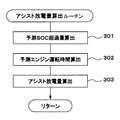
- FIG. 10 is a diagram illustrating a method for calculating the assist discharge amount.
- FIG. 11 is a diagram conceptually illustrating an example of a map of the assist discharge amount in a modification of the first embodiment.
- FIG. 12 is a diagram illustrating a schematic configuration of a control system for a hybrid vehicle according to a second embodiment.
- FIG. 13 is a diagram illustrating a schematic configuration of a control system for a hybrid vehicle according to a third embodiment.
- Example 1 of the present disclosure will be described with reference to FIGS.
- a hot water circuit 25 for heating is connected to a cooling water passage (water jacket) of the engine 11.
- the warm water circuit 25 is provided with a heater core 26 for heating and an electric water pump 27.
- This electric water pump 27 circulates cooling water (hot water) between the engine 11 and the heater core 26.
- a blower fan 28 that generates warm air is disposed in the vicinity of the heater core 26.
- the electric air conditioner 24 includes an electric compressor 29, an accumulator 30, an outdoor heat exchanger 31, an expansion valve 32, an indoor heat exchanger 33, and the like. Electric power is supplied from the high-voltage battery 20 to the electric compressor 29.
- the accelerator sensor 34 detects the amount of operation of the accelerator pedal, which is the accelerator opening.
- An operating position of the shift lever is detected by the shift switch 35.
- a brake operation (or a brake operation amount by a brake sensor) is detected by the brake switch 36.
- the vehicle speed is detected by the vehicle speed sensor 37.
- the temperature of the high voltage battery 20 is detected by the battery temperature sensor 38.
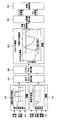
- the hybrid ECU 39 is a control device that comprehensively controls the entire vehicle, and detects the driving state of the vehicle by reading the output signals of the various sensors and switches described above.
- the hybrid ECU 39 transmits and receives control signals, data signals, and the like among the engine ECU 40, the AT-ECU 41, the MG-ECU 42, and the air conditioner ECU 43.
- the hybrid ECU 39 is a vehicle control device.
- the hybrid ECU 39 controls the engine 11, the transmission 14, the MGs 12 and 13, the DC-DC converter 21, the hot water heater 23, the electric air conditioner 24, and the like according to the driving state of the vehicle by the ECUs 40 to 43. Further, the hybrid ECU 39 transmits and receives control signals and data signals to and from the power supply ECU 44 that monitors the high-voltage battery 20 and the navigation device 45.
- the hybrid ECU 39 switches the travel mode between, for example, an engine travel mode, an assist travel mode, and an EV travel mode.
- engine running mode engine running is performed in which the vehicle 17 is driven by driving the wheels 17 only with the power of the engine 11.
- assist travel is performed in which the vehicle 17 travels by driving the wheels 17 with both the power of the engine 11 and the power of the second MG 13 or the MGs 12 and 13.
- EV traveling mode EV traveling is performed in which the vehicle is driven by driving the wheels 17 with only the power of the second MG 13 or the MGs 12 and 13.
- the hybrid ECU 39 switches the traveling mode to the regenerative power generation mode when braking the vehicle (for example, when generating a braking force when the accelerator is off or the brake is on).
- the second MG 13 or MG 12, 13 is driven by the power of the wheels 17, and regenerative power generation is performed to convert the kinetic energy of the vehicle into electric energy by the second MG 13 or MG 12, 13, which is the generated power.
- Regenerative power is charged to the high voltage battery 20.
- the SOC indicating the remaining capacity of the high-voltage battery 20 reaches an upper limit value, and there is a possibility that the high-voltage battery 20 is in a saturated state where regenerative power cannot be charged.
- the following control is performed by executing the routines of FIGS. 4 to 6 by the hybrid ECU 39. I do.
- the predicted SOC that is the SOC in the planned travel route is predicted based on the prediction result of the road gradient and the vehicle speed in the planned travel route of the vehicle.
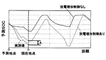
- the high voltage battery 20 is preliminarily set so that the high voltage battery 20 is not saturated based on the predicted SOC (that is, the SOC does not reach the upper limit value).
- Discharge increase control for increasing the discharge amount is executed. At that time, the discharge amount of the high-voltage battery 20 is increased by EV discharge so that the discharge of the high-voltage battery 20 is performed by assist discharge or EV traveling by assist travel.
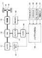
- the hybrid ECU 39 includes a road gradient prediction unit 46, a vehicle speed prediction unit 47, a travel output calculation unit 48, a battery output calculation unit 49, an SOC prediction unit 50, a discharge amount calculation unit 51, and a discharge control. Part 52.
- the vehicle speed prediction unit 47 travels based on own vehicle position information, travel route information, speed limit information from a navigation device, a locator, etc., traffic information from an advanced driving support system, weather information, surrounding information, etc. Predict the behavior of the vehicle speed up to a predetermined distance ahead on the planned route.
- the travel output calculation unit 48 calculates or predicts the behavior of the travel output up to a predetermined distance ahead on the planned travel route based on the prediction result of the road gradient and the vehicle speed on the planned travel route.
- the battery output calculation unit 49 calculates or predicts the behavior of charge / discharge power, which is the output of the high-voltage battery 20 up to a predetermined distance ahead in the planned travel route, based on the calculation result of the travel output in the planned travel route.
- a travel mode change pattern which is a travel pattern on the planned travel route, is predicted based on the behavior of the travel output on the planned travel route.
- the output of the high-voltage battery 20 is calculated based on the output (for example, generated power) of the MGs 12 and 13 during engine travel and the power consumption of the auxiliary device (for example, the electric compressor 29).
- the output of the high voltage battery 20 is calculated based on the outputs (for example, power consumption) of the MGs 12 and 13 during assist travel and the power consumption of the auxiliary machine.
- the output of the high voltage battery 20 is calculated based on the outputs (for example, power consumption) of the MGs 12 and 13 during EV travel, the power consumption of the auxiliary machine, and the like.
- the output of the high voltage battery 20 is calculated based on the outputs (for example, generated power) of the MGs 12 and 13 during the regenerative power generation and the power consumption of the auxiliary machine.
- the regenerative power generation amount exceeding the upper limit value based on the predicted SOC behavior (for example, the total value of the regenerative power amount predicted to be able to be charged if it is not saturated) ) Is calculated as the predicted SOC excess amount.
- the discharge amount calculation unit 51 based on the predicted SOC excess amount, the discharge amount of the high-voltage battery 20 by the assist discharge that is the assist discharge amount for the discharge increase control in the scheduled travel route or the EV discharge that is the EV discharge amount
- the amount of discharge of the high voltage battery 20 is calculated.
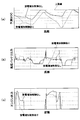
- the behavior of the predicted SOC when the discharge increase control is executed reaches the upper limit value based on the behavior of the first predicted SOC that is the predicted SOC when the discharge increase control is not executed.
- an assist discharge amount and an EV discharge amount for discharge increase control are set.
- the behavior of the output of the high-voltage battery 20 changes between when the discharge increase control is not executed and when the discharge increase control is executed, but the output of the engine 11 is set so that the traveling output is substantially the same. It ’s fine.
- the assist discharge amount and EV discharge amount are set so that the amount of electric power exceeding the predicted SOC excess amount is consumed in the assist discharge and EV discharge before the start of regenerative power generation that is predicted to reach the upper limit value first. You may make it do.
- the assist discharge amount or EV discharge amount may be set so that the amount of electric power exceeding the predicted SOC excess amount is consumed in the assist discharge or EV discharge. Further, the assist traveling period and the EV traveling period may be lengthened.
- the discharge controller 52 controls the engine 11, the MGs 12 and 13, etc. so as to realize the assist discharge amount and EV discharge amount for the discharge increase control in the planned travel route, thereby reducing the discharge amount of the high-voltage battery 20.
- the discharge increase control to be increased is executed.
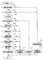
- the main control routine shown in FIG. 4 is repeatedly executed at a predetermined cycle during the power-on period of the hybrid ECU 39.
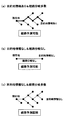
- this routine is started, first, at 101, it is determined whether it is difficult to predict the planned travel route. In this case, when the destination information of the vehicle is not obtained and the number of route branches in the traveling direction is greater than or equal to a predetermined value (for example, 1 or 2), it is determined that the predicted travel route is difficult to predict.
- a predetermined value for example, 1 or 2
- FIG. 7A if there is destination information, it is possible to predict a planned travel route even if there is a route branch in the traveling direction. Further, as shown in FIG. 7B, even if there is no destination information, the planned travel route can be predicted if there are no or few route branches in the traveling direction. Therefore, as shown in FIG. 7C, when the destination information is not obtained and the number of route branches in the traveling direction is equal to or greater than a predetermined value, it can be determined that it is difficult to predict the planned travel route.
- the charge amount (for example, charge) of the high voltage battery 20 is referred to with reference to the map of fuel consumption maximization charge / discharge amount shown in FIG. Power) or discharge amount (for example, discharge power) is set.
- the hybrid ECU 39 controls the engine 11, the MGs 12, 13 and the like so as to realize this charge amount or discharge amount.
- the process proceeds to 102.
- Whether or not the high voltage battery 20 has deteriorated is determined based on at least one of the temperature, voltage, internal resistance, etc. Judgment.
- the process proceeds to 112, and discharge increase control is prohibited.
- the processes 102 and 112 serve as a second prohibition unit. Thereafter, the process proceeds to 113, and the fuel consumption maximizing charge / discharge amount is set.
- the process proceeds to 103 and the actual SOC of the high voltage battery 20 is measured.
- the process proceeds to 114, where the charge amount (for example, charge power) of the high-voltage battery 20 is set to the sum of the power consumption of the auxiliary machines including the electric compressor 29. .
- the charge amount (for example, charge power) of the high-voltage battery 20 is set to the sum of the power consumption of the auxiliary machines including the electric compressor 29. .
- the power generation amount (for example, power generation power) of the first MG 12 or the MGs 12 and 13 is the total power consumption of the auxiliary machine including the electric compressor 29 that is the charge amount of the high-voltage battery 20.
- the processes 104 and 114 serve as an SOC reduction suppressing unit.
- the predicted SOC behavior deviates from the actual SOC behavior. It is determined whether or not.
- the processing proceeds to 106.
- a change in the travel route it is determined whether or not a change in the travel route has occurred.
- the travel route is changed, the road gradient, the vehicle speed, etc. change, and the change pattern of the travel mode, which is the travel output and travel pattern, changes, so the output of the high voltage battery 20 changes and the behavior of the SOC changes. To do. Therefore, the change of the travel route becomes a cause of SOC shift.
- the SOC deviation factor is vehicle control in which the predicted SOC behavior is expected to deviate from the actual SOC behavior.
- step 107 it is determined whether or not a change in the operating state of auxiliary equipment such as the electric air conditioner 24 and lights (for example, switch-on or switch-off) has occurred.
- auxiliary equipment such as the electric air conditioner 24 and lights (for example, switch-on or switch-off)
- the SOC deviation factor is vehicle control in which the predicted SOC behavior is expected to deviate from the actual SOC behavior.
- the process proceeds to 109.
- a change in road surface condition for example, road surface wetness due to rain, road surface snow accumulation due to snowfall, road surface freezing due to temperature drop, etc.
- the SOC deviation factor is an environmental change in which the behavior of the predicted SOC is expected to deviate from the actual behavior of the SOC.
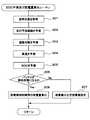
- the process proceeds to 203, and the behavior of the road gradient up to a predetermined distance ahead in the planned travel route is predicted based on the vehicle position information, the planned travel route, and the like. Thereafter, the process proceeds to 204, where the behavior of the vehicle speed up to a predetermined distance on the planned travel route is predicted based on the vehicle position information, the planned travel route, the speed limit information, the traffic information, the weather information, the peripheral information, and the like.
- the process 203 serves as a road gradient prediction unit
- the process 204 serves as a vehicle speed prediction unit.
- the process proceeds to 205, and the behavior of the travel output up to a predetermined distance ahead on the planned travel route is calculated based on the prediction result of the road gradient and the vehicle speed. Based on the calculation result of the travel output, the behavior of charge / discharge power, which is the output of the high voltage battery 20 up to a predetermined distance ahead in the planned travel route, is calculated. Based on the calculation result of the output of the high-voltage battery 20, the SOC behavior up to a predetermined distance ahead in the planned travel route is predicted. In the present embodiment, the process 205 serves as an SOC prediction unit.
- routine proceeds to 206, where it is determined whether or not the high voltage battery 20 is saturated so that the regenerative power cannot be charged, depending on whether or not the predicted SOC reaches the upper limit value.
- the routine proceeds to 207, where the fuel consumption maximizing charge / discharge amount setting (the same processing as 113 in FIG. 4) is performed. )I do.
- step 208 based on the predicted SOC excess amount, an assist discharge amount and an EV discharge amount for discharge increase control in the planned travel route are calculated. For example, when the discharge increase control is performed only by the assist discharge, the assist discharge amount calculation routine of FIG. 6 is executed at 208 to calculate the assist discharge amount for the discharge increase control.
- the processes 206 and 208 serve as a discharge control unit, and in the present embodiment, the processes 201 to 208 serve as a correction unit.
- the predicted SOC excess amount is calculated.
- the behavior of the predicted SOC excess amount up to a predetermined distance ahead in the planned travel route is calculated based on the behavior of the predicted SOC up to a predetermined distance ahead in the planned travel route.
- the process proceeds to 302 to calculate the predicted engine operation time.
- the behavior of the predicted engine operation time up to the predetermined distance ahead on the planned travel route is calculated based on the behavior of the predicted engine operation state up to the predetermined distance ahead on the planned travel route. .
- the process proceeds to 303 to calculate the assist discharge amount.
- the assist discharge amount is obtained by dividing the predicted SOC excess amount by the predicted engine operation time for each distance on the planned travel route, and the maximum value is determined as the final assist discharge amount.
- the command assist discharge amount is By controlling the engine 11 and the MGs 12 and 13 so as to realize this assist discharge amount, discharge increase control for increasing the discharge amount of the high-voltage battery 20 is executed.
- the SOC in the planned travel route is predicted based on the prediction result of the road gradient and the vehicle speed in the planned travel route of the vehicle.
- discharge increase control is executed to increase the discharge amount of the high voltage battery 20 in advance so that the high voltage battery 20 is not saturated based on the predicted SOC. . Accordingly, if the predicted SOC is correct, the high voltage battery 20 can be prevented from being saturated by controlling the SOC not to reach the upper limit value by the discharge increase control based on the predicted SOC.
- the discharge increase control it is determined whether or not the predicted SOC behavior is deviated from the actual SOC behavior or whether an SOC deviation factor has occurred.
- the prediction of the SOC on the planned travel route is performed again. Correct the discharge increase control. Thereby, even when the behavior of the predicted SOC is deviated from the actual behavior of the SOC, the predicted SOC can be corrected by performing the prediction of the SOC again.
- the discharge increase control is corrected based on the corrected predicted SOC, and the corrected discharge increase control is performed so that the SOC does not reach the upper limit value, thereby preventing the high voltage battery 20 from being saturated. can do. Thereby, it is possible to reliably prevent the high-voltage battery 20 from being saturated, to effectively use the regenerative power generation, and to effectively improve fuel efficiency.
- the SOC that is obtained by subtracting the increase in the amount of discharge due to the discharge increase control from the predicted time point of the predicted SOC to the current time from the predicted SOC of the current time when the discharge increase control is not executed is used as the discharge increase control. Obtained as the predicted SOC of the local point when executed.
- the difference between the predicted SOC at the local point when this discharge increase control is executed and the actual SOC at the local point is a predetermined value or more, the behavior of the predicted SOC is deviated from the actual SOC behavior. judge. In this way, it is possible to accurately determine that the behavior of the predicted SOC is deviated from the actual behavior of the SOC by comparing the predicted SOC when the discharge increase control is executed with the actual SOC. it can.
- the first MG 12 or MG 12, 13 when the actual SOC becomes a predetermined value or less, discharging of the high voltage battery 20 is prohibited, and the first MG 12 or MG 12, 13 is rotated by the power of the engine 11 to drive the first MG 12 or MG 12. , 13 generates electricity. If it does in this way, the excessive fall of SOC can be controlled.
- the discharge increase control is prohibited. Thereby, deterioration of the fuel consumption by the discharge increase control based on the uncertain predicted SOC can be prevented.
- the discharge increase control is prohibited when the high voltage battery 20 is deteriorated (that is, the deterioration state of the high voltage battery 20 is not less than a predetermined value).
- the discharge amount of the high voltage battery 20 is increased by the assist discharge for discharging the high voltage battery 20 by the assist traveling or the EV discharge for discharging the high voltage battery 20 by the EV traveling. Let If it does in this way, the amount of discharges of high voltage battery 20 can be increased, converting the electric power of high voltage battery 20 into the driving force of vehicles by assist discharge or EV discharge, and using effectively.
- the discharge amount of the high-voltage battery 20 may be increased by both the assist discharge and the EV discharge. However, the discharge amount of the high-voltage battery 20 by only one of the assist discharge and the EV discharge. May be increased.
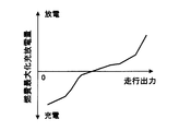
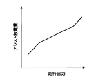
- the assist discharge amount corresponding to the travel output of the vehicle is calculated with reference to the assist discharge amount map shown in FIG.
- the assist discharge amount map is set so that the assist discharge amount increases as the traveling output of the vehicle increases, and the assist discharge amount decreases as the traveling output of the vehicle decreases.
- the engine 11 can be used in a region where the efficiency of the engine 11 is high without reducing the output of the engine 11 and the fuel efficiency is high. Can drive.
- the traveling output of the vehicle is large, even if the assist discharge power is increased, the output of the engine 11 can be increased and the engine can be operated in a region where the efficiency of the engine 11 is high.
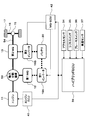
- Example 2 of the present disclosure will be described with reference to FIG.
- parts that are substantially the same as or similar to those in the first embodiment are denoted by the same reference numerals, and description thereof is omitted or simplified, and parts that are different from those in the first embodiment are mainly described.
- the clutch is not provided in the power transmission path from the engine 11 to the transmission 14, but the present invention is not limited to this.
- a clutch is provided between the engine 11 and the MG 12, or the MG 12 and the transmission are changed.
- a clutch may be provided between the machine 14 and the machine 14.
- a clutch may be built in the transmission 14. Further, the transmission 14 may be omitted.
- this indication is not limited to the hybrid vehicle of the structure shown to FIG.1, FIG.12, FIG.13, It can implement by applying to the hybrid vehicle of the various structures carrying an engine and MG as a motive power source of a vehicle.
- the method of determining whether or not the behavior of the predicted SOC is deviated from the actual behavior of the SOC is not limited to the method described in the above embodiment, and may be changed as appropriate.
- the difference between the current predicted SOC when the discharge increase control is not executed and the SOC obtained by adding the increase in discharge amount by the discharge increase control from the predicted time point of the predicted SOC to the current time to the actual SOC at the local point is a predetermined value. In the above case, it may be determined that the behavior of the predicted SOC is deviated from the actual behavior of the SOC.
- the present invention is not limited to this, and whether or not other vehicle control (unpredicted stopping, sudden acceleration, sudden deceleration, etc.) or environmental change (for example, change in temperature, atmospheric pressure, etc.) has occurred as a cause of SOC deviation. It may be determined.
- the function of generating electric power by rotating the MG with the power of the engine by prohibiting the discharge of the high voltage battery, and the discharge increase control when it is difficult to predict the planned travel route At least one of a function for prohibiting discharge and a function for prohibiting discharge increase control when the deterioration state of the battery is greater than or equal to a predetermined value may be omitted.
- the discharge amount of the high voltage battery is increased by assist discharge or EV discharge in the discharge increase control.
- the discharge amount of the high voltage battery may be increased by other methods. .
Landscapes
- Engineering & Computer Science (AREA)
- Transportation (AREA)
- Mechanical Engineering (AREA)
- Chemical & Material Sciences (AREA)
- Combustion & Propulsion (AREA)
- Life Sciences & Earth Sciences (AREA)
- Sustainable Development (AREA)
- Sustainable Energy (AREA)
- Power Engineering (AREA)
- Automation & Control Theory (AREA)
- Physics & Mathematics (AREA)
- Mathematical Physics (AREA)
- General Engineering & Computer Science (AREA)
- Theoretical Computer Science (AREA)
- Artificial Intelligence (AREA)
- Computational Linguistics (AREA)
- Data Mining & Analysis (AREA)
- Evolutionary Computation (AREA)
- Computing Systems (AREA)
- General Physics & Mathematics (AREA)
- Software Systems (AREA)
- Hybrid Electric Vehicles (AREA)
- Electric Propulsion And Braking For Vehicles (AREA)
Priority Applications (3)
| Application Number | Priority Date | Filing Date | Title |
|---|---|---|---|
| CN201680064401.0A CN108349486B (zh) | 2015-11-06 | 2016-10-06 | 车辆控制装置 |
| US15/765,158 US10946764B2 (en) | 2015-11-06 | 2016-10-06 | Controller for vehicle |
| DE112016005098.4T DE112016005098B4 (de) | 2015-11-06 | 2016-10-06 | Steuerungsvorrichtung für ein Fahrzeug |
Applications Claiming Priority (2)
| Application Number | Priority Date | Filing Date | Title |
|---|---|---|---|
| JP2015218983A JP6406215B2 (ja) | 2015-11-06 | 2015-11-06 | 車両の制御装置 |
| JP2015-218983 | 2015-11-06 |
Publications (1)
| Publication Number | Publication Date |
|---|---|
| WO2017077808A1 true WO2017077808A1 (ja) | 2017-05-11 |
Family
ID=58662393
Family Applications (1)
| Application Number | Title | Priority Date | Filing Date |
|---|---|---|---|
| PCT/JP2016/079720 Ceased WO2017077808A1 (ja) | 2015-11-06 | 2016-10-06 | 車両の制御装置 |
Country Status (5)
| Country | Link |
|---|---|
| US (1) | US10946764B2 (enExample) |
| JP (1) | JP6406215B2 (enExample) |
| CN (1) | CN108349486B (enExample) |
| DE (1) | DE112016005098B4 (enExample) |
| WO (1) | WO2017077808A1 (enExample) |
Cited By (4)
| Publication number | Priority date | Publication date | Assignee | Title |
|---|---|---|---|---|
| JP2019001351A (ja) * | 2017-06-16 | 2019-01-10 | 本田技研工業株式会社 | ハイブリッド車両 |
| JP2020171121A (ja) * | 2019-04-03 | 2020-10-15 | 三菱重工業株式会社 | 計画装置及び計画方法 |
| CN113942514A (zh) * | 2020-07-16 | 2022-01-18 | 上海汽车集团股份有限公司 | 能耗优化方法,装置及存储介质 |
| CN115648344A (zh) * | 2022-12-28 | 2023-01-31 | 成都普什信息自动化有限公司 | 一种rfid标签结构的模切方法及系统 |
Families Citing this family (28)
| Publication number | Priority date | Publication date | Assignee | Title |
|---|---|---|---|---|
| DE102015223588B4 (de) * | 2015-11-27 | 2025-10-23 | Bayerische Motoren Werke Aktiengesellschaft | Steuersystem mit mindestens einer elektronischen Steuereinheit zur Steuerung eines Verbrennungsmotors in einem Hybridfahrzeug |
| US10286899B2 (en) * | 2016-11-16 | 2019-05-14 | Ford Global Technologies, Llc | Operation of power electronics during battery communication loss |
| KR102443338B1 (ko) * | 2017-09-12 | 2022-09-15 | 현대자동차주식회사 | 배터리 충전 제어방법 및 시스템 |
| JP7013826B2 (ja) * | 2017-12-05 | 2022-02-01 | トヨタ自動車株式会社 | ハイブリッド自動車およびこれに搭載される制御装置 |
| JP7006311B2 (ja) | 2018-01-29 | 2022-01-24 | トヨタ自動車株式会社 | 電動車両及び電動車両の制御方法 |
| KR20200054512A (ko) * | 2018-11-12 | 2020-05-20 | 현대자동차주식회사 | 친환경 차량의 제동 제어 시스템 및 방법 |
| JP7119941B2 (ja) * | 2018-11-22 | 2022-08-17 | トヨタ自動車株式会社 | 車両の制御システム |
| JP7501250B2 (ja) * | 2019-11-12 | 2024-06-18 | トヨタ自動車株式会社 | 走行制御装置、方法およびプログラム |
| JP7238750B2 (ja) | 2019-12-11 | 2023-03-14 | トヨタ自動車株式会社 | 走行制御装置、方法、プログラムおよび車両 |
| CN111497821B (zh) * | 2020-04-08 | 2022-03-25 | 北京汽车股份有限公司 | 混动车辆的能量管理方法 |
| CN113968148B (zh) * | 2020-07-23 | 2025-04-22 | 厦门雅迅智联科技股份有限公司 | 一种增程式电动车的充电控制方法、系统和电动车 |
| JP7598235B2 (ja) * | 2020-12-07 | 2024-12-11 | 日産自動車株式会社 | 車両の制御方法及び車両の制御システム |
| CN112572404B (zh) * | 2020-12-24 | 2021-11-30 | 吉林大学 | 基于前方道路信息的重型商用车混合动力能量管理方法 |
| JP2022139826A (ja) * | 2021-03-12 | 2022-09-26 | 本田技研工業株式会社 | 車両の制御装置、車両の制御方法およびプログラム |
| CN112784824A (zh) * | 2021-03-18 | 2021-05-11 | 广州海格星航信息科技有限公司 | 一种智能驾驶深度学习模型管理方法、装置及系统 |
| US11708007B2 (en) * | 2021-08-02 | 2023-07-25 | Ford Global Technologies, Llc | Control systems and methods for modifying a battery state of charge signal |
| US12263754B2 (en) * | 2021-11-29 | 2025-04-01 | Caterpillar Inc. | Battery management for electric material- dispensing machine |
| US12038769B2 (en) | 2021-11-29 | 2024-07-16 | Caterpillar Global Mining Equipment Llc | Battery management for machine service operations |
| US12077065B2 (en) | 2021-11-29 | 2024-09-03 | Caterpillar Global Mining Equipment Llc | Brake control system for battery-powered machine |
| US12124266B2 (en) | 2021-11-29 | 2024-10-22 | Caterpillar Inc. | Battery support service vehicle |
| DE102022205065A1 (de) | 2022-05-20 | 2023-11-23 | Psa Automobiles Sa | Hybridantrieb für ein Kraftfahrzeug und Verfahren zum Betreiben desselben |
| US12236732B2 (en) * | 2022-07-06 | 2025-02-25 | International Engine Intellectual Property Company, Llc | Intelligent charge limit for high voltage batteries |
| CN115257407B (zh) * | 2022-08-16 | 2024-07-30 | 中联重科股份有限公司 | 增程式电动车辆的能量管理方法、终端及计算机存储介质 |
| JP7722302B2 (ja) * | 2022-09-06 | 2025-08-13 | トヨタ自動車株式会社 | 自動車 |
| CN116101255B (zh) * | 2023-02-10 | 2024-03-08 | 广州汽车集团股份有限公司 | 发动机的启停控制方法及装置、设备、介质 |
| EP4665603A1 (en) * | 2023-02-15 | 2025-12-24 | ABB Schweiz AG | Method of determining a road surface condition, road, surface condition monitoring system, for monitoring an industrial site, and computer program product |
| US20240425030A1 (en) * | 2023-06-26 | 2024-12-26 | Fca Us Llc | Intelligent optimized energy storage control for electrified vehicles |
| CN119975098B (zh) * | 2025-03-21 | 2025-10-24 | 潍柴动力股份有限公司 | 一种增程矿卡的soc规划方法及相关装置 |
Citations (5)
| Publication number | Priority date | Publication date | Assignee | Title |
|---|---|---|---|---|
| JP2007050888A (ja) * | 2006-09-25 | 2007-03-01 | Aisin Aw Co Ltd | ハイブリッド車両の駆動制御システム |
| JP2009001099A (ja) * | 2007-06-20 | 2009-01-08 | Denso Corp | 充放電管理装置および充放電管理装置用のプログラム |
| JP2009274610A (ja) * | 2008-05-15 | 2009-11-26 | Honda Motor Co Ltd | ハイブリッド車の制御装置 |
| JP2010125868A (ja) * | 2008-11-25 | 2010-06-10 | Denso Corp | 充放電計画装置 |
| JP2012050299A (ja) * | 2010-08-30 | 2012-03-08 | Denso Corp | 車両用充放電管理システム |
Family Cites Families (9)
| Publication number | Priority date | Publication date | Assignee | Title |
|---|---|---|---|---|
| DE10035027A1 (de) | 2000-07-19 | 2002-01-31 | Daimler Chrysler Ag | Verfahren zur Steuerung des Betriebsmodus von Fahrzeugen mit Hybridantrieben |
| JP3904388B2 (ja) | 2000-12-04 | 2007-04-11 | 松下電器産業株式会社 | ハイブリッド自動車の制御装置 |
| JP4442646B2 (ja) * | 2007-06-20 | 2010-03-31 | 株式会社デンソー | 車両用発電制御装置及び制御システム |
| US8190318B2 (en) * | 2008-04-15 | 2012-05-29 | The Uwm Research Foundation, Inc. | Power management systems and methods in a hybrid vehicle |
| WO2013018208A1 (ja) * | 2011-08-03 | 2013-02-07 | トヨタ自動車株式会社 | ハイブリッド車両およびその制御方法 |
| CN102765388B (zh) * | 2012-07-03 | 2014-09-10 | 清华大学 | 一种基于多信息融合的整车控制方法 |
| US10703219B2 (en) * | 2013-10-04 | 2020-07-07 | Ford Global Technologies, Llc | Vehicle battery charge setpoint control |
| JP2015218983A (ja) | 2014-05-20 | 2015-12-07 | 積水化学工業株式会社 | 採熱システムの施工方法 |
| CN104260724B (zh) * | 2014-09-22 | 2017-02-15 | 李治良 | 一种车辆智能预测控制系统及其方法 |
-
2015
- 2015-11-06 JP JP2015218983A patent/JP6406215B2/ja active Active
-
2016
- 2016-10-06 CN CN201680064401.0A patent/CN108349486B/zh active Active
- 2016-10-06 DE DE112016005098.4T patent/DE112016005098B4/de active Active
- 2016-10-06 WO PCT/JP2016/079720 patent/WO2017077808A1/ja not_active Ceased
- 2016-10-06 US US15/765,158 patent/US10946764B2/en active Active
Patent Citations (5)
| Publication number | Priority date | Publication date | Assignee | Title |
|---|---|---|---|---|
| JP2007050888A (ja) * | 2006-09-25 | 2007-03-01 | Aisin Aw Co Ltd | ハイブリッド車両の駆動制御システム |
| JP2009001099A (ja) * | 2007-06-20 | 2009-01-08 | Denso Corp | 充放電管理装置および充放電管理装置用のプログラム |
| JP2009274610A (ja) * | 2008-05-15 | 2009-11-26 | Honda Motor Co Ltd | ハイブリッド車の制御装置 |
| JP2010125868A (ja) * | 2008-11-25 | 2010-06-10 | Denso Corp | 充放電計画装置 |
| JP2012050299A (ja) * | 2010-08-30 | 2012-03-08 | Denso Corp | 車両用充放電管理システム |
Cited By (8)
| Publication number | Priority date | Publication date | Assignee | Title |
|---|---|---|---|---|
| JP2019001351A (ja) * | 2017-06-16 | 2019-01-10 | 本田技研工業株式会社 | ハイブリッド車両 |
| US11312358B2 (en) | 2017-06-16 | 2022-04-26 | Honda Motor Co., Ltd. | Hybrid vehicle |
| JP2020171121A (ja) * | 2019-04-03 | 2020-10-15 | 三菱重工業株式会社 | 計画装置及び計画方法 |
| JP7267814B2 (ja) | 2019-04-03 | 2023-05-02 | 三菱重工業株式会社 | 計画装置及び計画方法 |
| CN113942514A (zh) * | 2020-07-16 | 2022-01-18 | 上海汽车集团股份有限公司 | 能耗优化方法,装置及存储介质 |
| CN113942514B (zh) * | 2020-07-16 | 2023-04-14 | 上海汽车集团股份有限公司 | 能耗优化方法,装置及存储介质 |
| CN115648344A (zh) * | 2022-12-28 | 2023-01-31 | 成都普什信息自动化有限公司 | 一种rfid标签结构的模切方法及系统 |
| CN115648344B (zh) * | 2022-12-28 | 2023-03-21 | 成都普什信息自动化有限公司 | 一种rfid标签结构的模切方法及系统 |
Also Published As
| Publication number | Publication date |
|---|---|
| JP6406215B2 (ja) | 2018-10-17 |
| US10946764B2 (en) | 2021-03-16 |
| US20180273021A1 (en) | 2018-09-27 |
| DE112016005098B4 (de) | 2024-06-06 |
| JP2017087915A (ja) | 2017-05-25 |
| CN108349486B (zh) | 2021-11-30 |
| DE112016005098T5 (de) | 2018-08-02 |
| CN108349486A (zh) | 2018-07-31 |
Similar Documents
| Publication | Publication Date | Title |
|---|---|---|
| JP6406215B2 (ja) | 車両の制御装置 | |
| JP6436071B2 (ja) | 車両の制御装置 | |
| JP6507625B2 (ja) | ハイブリッド車の制御装置 | |
| JP6089887B2 (ja) | ハイブリッド車の制御装置 | |
| KR100906908B1 (ko) | 하이브리드 전기 차량의 배터리 충전량 제어 방법 | |
| KR101836250B1 (ko) | 구동 모터를 구비한 차량의 dc 컨버터의 출력 전압을 제어하는 방법 및 장치 | |
| JP6264258B2 (ja) | 車両の制御装置 | |
| JP2008150014A (ja) | ハイブリッド電気車両のアイドリング充電時の発電制御方法 | |
| US20150274022A1 (en) | Power generation control device | |
| KR20140079156A (ko) | 하이브리드 차량의 모터의 토크 결정 방법 및 시스템 | |
| US20120139481A1 (en) | Battery charge control apparatus | |
| JP6435789B2 (ja) | ハイブリッド駆動車両の出力制御装置 | |
| CN101772444A (zh) | 混合动力车辆、混合动力车辆的控制方法以及存储有用于使计算机执行该控制方法的程序的计算机能够读取的存储介质 | |
| KR101927180B1 (ko) | 구동 모터를 구비한 차량의 보조 배터리를 충전하는 방법 및 장치 | |
| KR20190056152A (ko) | 마일드 하이브리드 차량의 전력 제어 방법 및 장치 | |
| JP2012240566A (ja) | ハイブリッド車両の電気走行制御装置 | |
| WO2017135307A1 (ja) | 車両の空調装置 | |
| CN115871518A (zh) | 用于电能存储装置的热管理的方法和系统 | |
| JP6070531B2 (ja) | ハイブリッド車の制御装置 | |
| JP6032192B2 (ja) | ハイブリッド車の制御装置 | |
| JP2016120740A (ja) | ハイブリッド車両の制御装置 |
Legal Events
| Date | Code | Title | Description |
|---|---|---|---|
| 121 | Ep: the epo has been informed by wipo that ep was designated in this application |
Ref document number: 16861875 Country of ref document: EP Kind code of ref document: A1 |
|
| WWE | Wipo information: entry into national phase |
Ref document number: 15765158 Country of ref document: US |
|
| WWE | Wipo information: entry into national phase |
Ref document number: 112016005098 Country of ref document: DE |
|
| 122 | Ep: pct application non-entry in european phase |
Ref document number: 16861875 Country of ref document: EP Kind code of ref document: A1 |