WO2017073561A1 - レーザ処理装置整流装置およびレーザ処理装置 - Google Patents
レーザ処理装置整流装置およびレーザ処理装置 Download PDFInfo
- Publication number
- WO2017073561A1 WO2017073561A1 PCT/JP2016/081580 JP2016081580W WO2017073561A1 WO 2017073561 A1 WO2017073561 A1 WO 2017073561A1 JP 2016081580 W JP2016081580 W JP 2016081580W WO 2017073561 A1 WO2017073561 A1 WO 2017073561A1
- Authority
- WO
- WIPO (PCT)
- Prior art keywords
- gas
- laser processing
- transmission region
- processing apparatus
- gas supply
- Prior art date
- Legal status (The legal status is an assumption and is not a legal conclusion. Google has not performed a legal analysis and makes no representation as to the accuracy of the status listed.)
- Ceased
Links
Images



Classifications
-
- B—PERFORMING OPERATIONS; TRANSPORTING
- B23—MACHINE TOOLS; METAL-WORKING NOT OTHERWISE PROVIDED FOR
- B23K—SOLDERING OR UNSOLDERING; WELDING; CLADDING OR PLATING BY SOLDERING OR WELDING; CUTTING BY APPLYING HEAT LOCALLY, e.g. FLAME CUTTING; WORKING BY LASER BEAM
- B23K26/00—Working by laser beam, e.g. welding, cutting or boring
- B23K26/14—Working by laser beam, e.g. welding, cutting or boring using a fluid stream, e.g. a jet of gas, in conjunction with the laser beam; Nozzles therefor
- B23K26/142—Working by laser beam, e.g. welding, cutting or boring using a fluid stream, e.g. a jet of gas, in conjunction with the laser beam; Nozzles therefor for the removal of by-products
-
- H—ELECTRICITY
- H10—SEMICONDUCTOR DEVICES; ELECTRIC SOLID-STATE DEVICES NOT OTHERWISE PROVIDED FOR
- H10P—GENERIC PROCESSES OR APPARATUS FOR THE MANUFACTURE OR TREATMENT OF DEVICES COVERED BY CLASS H10
- H10P72/00—Handling or holding of wafers, substrates or devices during manufacture or treatment thereof
- H10P72/04—Apparatus for manufacture or treatment
- H10P72/0431—Apparatus for thermal treatment
- H10P72/0436—Apparatus for thermal treatment mainly by radiation
-
- B—PERFORMING OPERATIONS; TRANSPORTING
- B23—MACHINE TOOLS; METAL-WORKING NOT OTHERWISE PROVIDED FOR
- B23K—SOLDERING OR UNSOLDERING; WELDING; CLADDING OR PLATING BY SOLDERING OR WELDING; CUTTING BY APPLYING HEAT LOCALLY, e.g. FLAME CUTTING; WORKING BY LASER BEAM
- B23K26/00—Working by laser beam, e.g. welding, cutting or boring
- B23K26/02—Positioning or observing the workpiece, e.g. with respect to the point of impact; Aligning, aiming or focusing the laser beam
- B23K26/06—Shaping the laser beam, e.g. by masks or multi-focusing
- B23K26/062—Shaping the laser beam, e.g. by masks or multi-focusing by direct control of the laser beam
- B23K26/0622—Shaping the laser beam, e.g. by masks or multi-focusing by direct control of the laser beam by shaping pulses
-
- B—PERFORMING OPERATIONS; TRANSPORTING
- B23—MACHINE TOOLS; METAL-WORKING NOT OTHERWISE PROVIDED FOR
- B23K—SOLDERING OR UNSOLDERING; WELDING; CLADDING OR PLATING BY SOLDERING OR WELDING; CUTTING BY APPLYING HEAT LOCALLY, e.g. FLAME CUTTING; WORKING BY LASER BEAM
- B23K26/00—Working by laser beam, e.g. welding, cutting or boring
- B23K26/02—Positioning or observing the workpiece, e.g. with respect to the point of impact; Aligning, aiming or focusing the laser beam
- B23K26/06—Shaping the laser beam, e.g. by masks or multi-focusing
- B23K26/073—Shaping the laser spot
- B23K26/0738—Shaping the laser spot into a linear shape
-
- B—PERFORMING OPERATIONS; TRANSPORTING
- B23—MACHINE TOOLS; METAL-WORKING NOT OTHERWISE PROVIDED FOR
- B23K—SOLDERING OR UNSOLDERING; WELDING; CLADDING OR PLATING BY SOLDERING OR WELDING; CUTTING BY APPLYING HEAT LOCALLY, e.g. FLAME CUTTING; WORKING BY LASER BEAM
- B23K26/00—Working by laser beam, e.g. welding, cutting or boring
- B23K26/08—Devices involving relative movement between laser beam and workpiece
- B23K26/083—Devices involving movement of the workpiece in at least one axial direction
-
- B—PERFORMING OPERATIONS; TRANSPORTING
- B23—MACHINE TOOLS; METAL-WORKING NOT OTHERWISE PROVIDED FOR
- B23K—SOLDERING OR UNSOLDERING; WELDING; CLADDING OR PLATING BY SOLDERING OR WELDING; CUTTING BY APPLYING HEAT LOCALLY, e.g. FLAME CUTTING; WORKING BY LASER BEAM
- B23K26/00—Working by laser beam, e.g. welding, cutting or boring
- B23K26/14—Working by laser beam, e.g. welding, cutting or boring using a fluid stream, e.g. a jet of gas, in conjunction with the laser beam; Nozzles therefor
- B23K26/1462—Nozzles; Features related to nozzles
- B23K26/1464—Supply to, or discharge from, nozzles of media, e.g. gas, powder, wire
- B23K26/1476—Features inside the nozzle for feeding the fluid stream through the nozzle
-
- B—PERFORMING OPERATIONS; TRANSPORTING
- B23—MACHINE TOOLS; METAL-WORKING NOT OTHERWISE PROVIDED FOR
- B23K—SOLDERING OR UNSOLDERING; WELDING; CLADDING OR PLATING BY SOLDERING OR WELDING; CUTTING BY APPLYING HEAT LOCALLY, e.g. FLAME CUTTING; WORKING BY LASER BEAM
- B23K26/00—Working by laser beam, e.g. welding, cutting or boring
- B23K26/352—Working by laser beam, e.g. welding, cutting or boring for surface treatment
-
- B—PERFORMING OPERATIONS; TRANSPORTING
- B23—MACHINE TOOLS; METAL-WORKING NOT OTHERWISE PROVIDED FOR
- B23K—SOLDERING OR UNSOLDERING; WELDING; CLADDING OR PLATING BY SOLDERING OR WELDING; CUTTING BY APPLYING HEAT LOCALLY, e.g. FLAME CUTTING; WORKING BY LASER BEAM
- B23K26/00—Working by laser beam, e.g. welding, cutting or boring
- B23K26/352—Working by laser beam, e.g. welding, cutting or boring for surface treatment
- B23K26/354—Working by laser beam, e.g. welding, cutting or boring for surface treatment by melting
-
- C—CHEMISTRY; METALLURGY
- C03—GLASS; MINERAL OR SLAG WOOL
- C03B—MANUFACTURE, SHAPING, OR SUPPLEMENTARY PROCESSES
- C03B25/00—Annealing glass products
- C03B25/02—Annealing glass products in a discontinuous way
-
- C—CHEMISTRY; METALLURGY
- C03—GLASS; MINERAL OR SLAG WOOL
- C03B—MANUFACTURE, SHAPING, OR SUPPLEMENTARY PROCESSES
- C03B25/00—Annealing glass products
- C03B25/02—Annealing glass products in a discontinuous way
- C03B25/025—Glass sheets
-
- H—ELECTRICITY
- H10—SEMICONDUCTOR DEVICES; ELECTRIC SOLID-STATE DEVICES NOT OTHERWISE PROVIDED FOR
- H10P—GENERIC PROCESSES OR APPARATUS FOR THE MANUFACTURE OR TREATMENT OF DEVICES COVERED BY CLASS H10
- H10P14/00—Formation of materials, e.g. in the shape of layers or pillars
- H10P14/20—Formation of materials, e.g. in the shape of layers or pillars of semiconductor materials
- H10P14/34—Deposited materials, e.g. layers
- H10P14/3451—Structure
- H10P14/3452—Microstructure
- H10P14/3454—Amorphous
-
- H—ELECTRICITY
- H10—SEMICONDUCTOR DEVICES; ELECTRIC SOLID-STATE DEVICES NOT OTHERWISE PROVIDED FOR
- H10P—GENERIC PROCESSES OR APPARATUS FOR THE MANUFACTURE OR TREATMENT OF DEVICES COVERED BY CLASS H10
- H10P14/00—Formation of materials, e.g. in the shape of layers or pillars
- H10P14/20—Formation of materials, e.g. in the shape of layers or pillars of semiconductor materials
- H10P14/38—Formation of materials, e.g. in the shape of layers or pillars of semiconductor materials characterised by treatments done after the formation of the materials
- H10P14/3802—Crystallisation or recrystallisation of non-monocrystalline semiconductor materials, e.g. regrowth
- H10P14/3808—Crystallisation or recrystallisation of non-monocrystalline semiconductor materials, e.g. regrowth using laser beams
- H10P14/3816—Pulsed laser beam
-
- B—PERFORMING OPERATIONS; TRANSPORTING
- B23—MACHINE TOOLS; METAL-WORKING NOT OTHERWISE PROVIDED FOR
- B23K—SOLDERING OR UNSOLDERING; WELDING; CLADDING OR PLATING BY SOLDERING OR WELDING; CUTTING BY APPLYING HEAT LOCALLY, e.g. FLAME CUTTING; WORKING BY LASER BEAM
- B23K2101/00—Articles made by soldering, welding or cutting
- B23K2101/18—Sheet panels
-
- B—PERFORMING OPERATIONS; TRANSPORTING
- B23—MACHINE TOOLS; METAL-WORKING NOT OTHERWISE PROVIDED FOR
- B23K—SOLDERING OR UNSOLDERING; WELDING; CLADDING OR PLATING BY SOLDERING OR WELDING; CUTTING BY APPLYING HEAT LOCALLY, e.g. FLAME CUTTING; WORKING BY LASER BEAM
- B23K2101/00—Articles made by soldering, welding or cutting
- B23K2101/36—Electric or electronic devices
- B23K2101/40—Semiconductor devices
-
- B—PERFORMING OPERATIONS; TRANSPORTING
- B23—MACHINE TOOLS; METAL-WORKING NOT OTHERWISE PROVIDED FOR
- B23K—SOLDERING OR UNSOLDERING; WELDING; CLADDING OR PLATING BY SOLDERING OR WELDING; CUTTING BY APPLYING HEAT LOCALLY, e.g. FLAME CUTTING; WORKING BY LASER BEAM
- B23K2103/00—Materials to be soldered, welded or cut
- B23K2103/50—Inorganic materials other than metals or composite materials
-
- H—ELECTRICITY
- H10—SEMICONDUCTOR DEVICES; ELECTRIC SOLID-STATE DEVICES NOT OTHERWISE PROVIDED FOR
- H10P—GENERIC PROCESSES OR APPARATUS FOR THE MANUFACTURE OR TREATMENT OF DEVICES COVERED BY CLASS H10
- H10P14/00—Formation of materials, e.g. in the shape of layers or pillars
- H10P14/20—Formation of materials, e.g. in the shape of layers or pillars of semiconductor materials
- H10P14/34—Deposited materials, e.g. layers
- H10P14/3402—Deposited materials, e.g. layers characterised by the chemical composition
- H10P14/3404—Deposited materials, e.g. layers characterised by the chemical composition being Group IVA materials
- H10P14/3411—Silicon, silicon germanium or germanium
-
- H—ELECTRICITY
- H10—SEMICONDUCTOR DEVICES; ELECTRIC SOLID-STATE DEVICES NOT OTHERWISE PROVIDED FOR
- H10P—GENERIC PROCESSES OR APPARATUS FOR THE MANUFACTURE OR TREATMENT OF DEVICES COVERED BY CLASS H10
- H10P14/00—Formation of materials, e.g. in the shape of layers or pillars
- H10P14/20—Formation of materials, e.g. in the shape of layers or pillars of semiconductor materials
- H10P14/38—Formation of materials, e.g. in the shape of layers or pillars of semiconductor materials characterised by treatments done after the formation of the materials
- H10P14/3802—Crystallisation or recrystallisation of non-monocrystalline semiconductor materials, e.g. regrowth
- H10P14/382—Scanning of a beam
Definitions
- the present invention relates to a laser processing apparatus rectifier and a laser processing apparatus that can form a local gas atmosphere and perform processing by irradiating an object to be processed with laser light.
- An apparatus that performs annealing by irradiating a laser beam to a silicon semiconductor film or the like on a substrate to form a local gas atmosphere surrounding a region irradiated with laser light on the substrate is known. Yes.
- FIG. 6 is a front view showing a conventional related apparatus.
- a laser introduction window 52 is provided in a laser irradiation cylinder 51 that introduces a laser beam 50 and irradiates the substrate 70.
- Horizontal rectifying plates 53 and 54 are respectively provided on both lower sides of the laser irradiation cylinder 51, and the laser beam 50 is transmitted through the laser transmission hole 51 ⁇ / b> B between the rectifying plates 53 and 54.
- the substrate 70 is placed on a sample stage 60 that is positioned below the laser processing cylinder 51 and is movable in the horizontal direction. In this state, the current plates 53 and 54 and the substrate 70 have a predetermined distance.
- a gas supply hole 51A is formed in the gas irradiation cylinder 51, and a predetermined gas can be supplied into the gas irradiation cylinder 51 from the outside.
- the gas supplied into the gas irradiation cylinder 51 is blown downward through the laser beam transmitting hole 51B, collides with the substrate 70, and then flows outward through the gap between the rectifying plates 53 and 54 and the substrate 70 to be localized.
- a gas atmosphere is formed.
- atmosphere control means for enclosing a region irradiated with a laser beam, a plurality of gas supply means capable of supplying different gases into the atmosphere control means, and the atmosphere control supplied by the gas supply means
- a laser annealing apparatus having exhaust adjusting means for exhausting gas in the means from the annealing chamber.
- gas is continuously ejected from the vicinity of the optical path of laser light toward the substrate in order to form a gas atmosphere.
- a gas flow is jetted from above into the laser irradiation position, turbulence occurs at the laser irradiation position.
- the gas flow to be injected has been improved to be a laminar flow.
- attempts have been made to slow down the gas flow rate and reduce the turbulent flow, but it is difficult to form a uniform atmosphere that is the original purpose.
- the present invention has been made to solve the above-described problems of the prior art, and allows a uniform atmosphere to be formed by an arbitrary gas species by flowing a gas flow along the object to be processed. It is an object of the present invention to provide a rectifying device and a laser processing device.
- the first present invention is A rectifier provided in a laser processing apparatus that performs processing by irradiating a target object having a plate surface with laser light, A plate surface of the object to be processed is disposed on an end side of a transmission region through which laser light is transmitted and irradiated to the object to be processed held by the laser processing apparatus, and spaced from the object to be processed.
- a rectifying unit having a rectifying surface extending outward of the transmission region along the line;
- a gas supply unit that supplies gas to a gap between one side of the rectifying surface and the transmission region at a position separated from the transmission region in a state of being installed in the transmission region;
- the gas in the gap between the rectifying surface and the object to be processed on the one side and the other side sandwiching the transmission region at a position separated from the transmission region in a state of being installed in the transmission region.
- a gas discharge portion for discharging outside the gap.
- the gas is supplied and discharged at a position separated from the transmission region by being installed in the laser processing apparatus, a uniform flow velocity and pressure distribution is formed in the vicinity of the irradiation region, and a stable local gas is formed. An atmosphere is formed.
- the laser processing device rectifier according to the second aspect of the present invention is characterized in that, in the first aspect of the present invention, the rectifying portion has a shape extending outward with respect to the entire periphery of the transmission region.
- a stable local gas atmosphere can be obtained around the permeation region.
- the rectifying unit in the first or second aspect of the present invention, has a size in which the rectifying surface extends outside the gas discharge unit with respect to the transmission region.
- the gas discharge part has a gas suction part for sucking gas from the gap.
- the gas in the entire atmosphere can be sucked and cleaned from the outside of the suction position of the gas discharge portion.
- a laser processing apparatus is a laser processing apparatus for performing processing by irradiating a target object having a plate surface with laser light.
- a rectifying unit having a rectifying surface extending outward from the transmissive region along the plate surface of the object to be processed at an interval from the end side of the transmissive region;
- a gas supply unit that supplies gas to a gap between one side of the rectifying surface and the transmission region at a position separated from the transmission region;
- a gas discharge unit that discharges the gas in the gap between the rectifying surface and the object to be processed to the outside on the one side and the other side sandwiching the transmission area at a position separated from the transmission area; It is characterized by having.
- gas is supplied and discharged at a position separated from the permeation region, a uniform flow velocity and pressure distribution are formed in the vicinity of the irradiation region, and a stable local gas atmosphere is formed.
- a laser processing apparatus is the laser processing apparatus according to the fourth aspect, wherein the laser beam has a line beam shape on the object to be processed, and the transmission region is a short axis of the line beam shape. According to the direction and the major axis direction, each has a long shape having a minor axis and a major axis,
- the rectifying unit is characterized in that the rectifying surface extends outward of the transmission region on both the short axis side and the long axis side of the transmission region.
- a stable local gas atmosphere can be obtained on the outer side in the major axis direction and the outer side in the minor axis direction of the transmission region.
- the rectifying surface is outside in the major axis direction from the major axis end of the laser beam on the major axis end side of the transmission region. It is characterized by extending 20 mm or more.
- the extension distance is smaller than 20 mm, the laser beam is easily affected from the outside of the long axis end portion. It is more desirable that the extension distance is 50 mm or more.
- a laser processing apparatus is the laser processing apparatus according to any one of the fourth to sixth aspects of the present invention, wherein the gas flow generated by the gas supply and the gas discharge is generated by supplying and discharging the gas. Is provided so as to cover an irradiation region irradiated to the object to be processed.
- the present invention it is possible to cover the irradiation area where the laser beam is irradiated on the object to be processed by the laminar flow of gas and place it in a stable local gas atmosphere.
- the laser processing apparatus is the laser processing apparatus according to the seventh aspect, wherein the laser beam has a line beam shape on the object to be processed, and the transmission region is a short axis of the line beam shape.
- the transmission region is a short axis of the line beam shape.
- each has a long shape having a minor axis and a major axis,
- the gas supply unit and the gas discharge unit supply and discharge gas in a length range exceeding both ends of the major axis width of the laser beam on the irradiation surface with the transmission region interposed therebetween, respectively. .
- the irradiation region of the line beam-shaped laser beam can be reliably covered with the gas flow.
- the rectifying unit supplies gas by the gas supply unit on the one side with respect to the transmission region.
- the rectifying surface further extends to the outside of the position, and the rectifying surface extends to the gas discharge part on the other side.
- a laminar flow of gas can be generated outside the gas supply position to prevent gas inflow of the entire atmosphere.
- the laser processing apparatus is the laser processing apparatus according to any one of the fourth to ninth aspects of the present invention, wherein the rectifying unit has a gas discharge position by the gas discharge unit with the rectifying surface being based on the transmission region.
- the gas discharge part has a gas suction part for sucking gas from the gap.
- gas is efficiently discharged by the gas suction unit, and a more stable laminar flow is formed in the gap.
- the gas suction position the gas outside the region is sucked as a laminar flow and floated. Things can be excluded.
- the laser processing apparatus is the laser processing apparatus according to the tenth aspect, wherein the gas suction part communicates with the gap, and is a direction between a direction perpendicular to the rectifying surface and an outer direction of the gas discharge part. It has a gas discharge passage through which gas flows.
- the void gas can be sucked and discharged more efficiently.
- the length of the rectifying surface extending outside the gas supply position by the gas supply unit is the gas supply position. And a gap between the gas discharge position and the gas discharge position.
- the introduction of gas from the entire atmosphere can be surely eliminated by having the rectifying surface with a sufficient length outside the gas supply position.
- the extension length is equal to or shorter than the interval between the gas supply position and the gas discharge position, the above-described exclusion effect cannot be obtained sufficiently.
- the laser processing apparatus according to the twelfth aspect of the present invention, wherein the length of the rectifying surface extends outside the gas discharge position by the gas discharge portion is the gas supply position and the gas. It is characterized by being larger than the interval between the discharge positions.
- the rectifying surface by having the rectifying surface with a sufficient length outside the gas discharge position, it is possible to reliably perform gas suction from the entire atmosphere by a stable laminar flow.
- the extension length is equal to or smaller than the interval between the gas supply position and the gas discharge position, the suction effect cannot be stably obtained.
- the gas supply unit communicates with the gap, and is perpendicular to the rectifying surface and the gas supply unit. It has the gas supply path through which gas flows in the direction between the inner side direction.
- gas can be stably introduced into the gap, and a laminar flow of gas can be stably formed at an early stage.
- the laser processing apparatus according to any one of the fourth to fourteenth aspects, further comprising a moving device that moves the object to be processed.
- a moving device that moves the object to be processed.
- a floating gas or the like before the laser light irradiation, a floating gas or the like can be sent forward and discharged while forming a local gas atmosphere on the surface of the object to be processed, so that stable processing can be performed. become.
- the moving device can reciprocate, and the gas supply unit and the gas discharge unit can be switched according to the moving direction. It is characterized by being.
- gas can be supplied and discharged in the direction according to the moving direction when the object to be processed is reciprocated.
- the laser processing apparatus according to any one of the fourth to sixteenth aspects of the present invention, wherein the gas supply position by the gas supply section is 50 mm or more from the adjacent end portion side of the laser beam at the irradiation position. It is characterized by having the distance of.
- the gas supply position and the laser beam irradiation position are sufficiently separated, a laminar flow in which the gas flow is stable before and after the irradiation position can be formed.
- the flow can be reliably eliminated. If the distance does not satisfy the conditions, it becomes difficult to reliably obtain a stable laminar flow.
- the distance is more preferably 150 mm or more.
- the gas discharge position by the gas discharge section is 50 mm or more from the end portion side of the laser beam close to the irradiation position. It is characterized by having the distance of.
- the irradiation position of the laser beam and the gas discharge position are sufficiently separated, a laminar flow in which the gas flow is stable before and after the irradiation position can be formed.
- the flow can be reliably eliminated. If the distance does not satisfy the conditions, it becomes difficult to reliably obtain a stable laminar flow.
- the distance is more preferably 150 mm or more.
- the distance between the gas supply position and the irradiation position near the end of the laser beam, and the distance between the irradiation position near the end of the laser beam and the gas supply position have a distance of 20 mm or more. It is desirable that the thickness is 50 mm or more.
- the laser processing apparatus according to any one of the fourth to eighteenth aspects, wherein the distance between the rectifying surface and the object to be processed is in the range of 1 to 20 mm. .
- the gas flow can be made to be a stable laminar flow by appropriately setting the distance between the rectifying surface and the object to be processed.
- a laser processing apparatus is the laser processing apparatus according to any one of the fourth to nineteenth aspects of the present invention, wherein the object to be processed has a non-single-crystal semiconductor layer, and the processing with the laser beam is recrystallization. It is characterized by that.
- the gas in the region irradiated with the laser beam, the gas is not injected toward the object to be processed, so there is no factor that disturbs the laminar flow due to any gas, and the gas moves along the plate surface of the object to be processed.
- a uniform flow velocity and pressure distribution are formed, and a stable local gas atmosphere is formed.
- substances generated from the object to be processed such as vapor and fine particles, to be discharged in one direction, and can be quickly removed from the optical path of the laser.
- substances generated from the irradiated object such as vapor and fine particles, it can be dealt with by increasing the flow velocity.
- the rectifying plate for forming the laminar flow can be designed long without being bent, more rectified rectification can be formed.
- the laser processing apparatus 1 is configured such that a sample table 10 having a plane direction axis (X and Y) is installed on a moving table 11 ⁇ / b> A and can move in the illustrated left-right direction, illustrated depth, and forward direction.
- a long laser beam introduction window 15 is formed above the sample stage 10.
- the moving table 11A moves the sample table 10 by a driving device (not shown), and the moving table 11A and the driving device (not shown) constitute the moving device 11 of the present invention.
- a substrate 100 described later is placed on the sample stage 10.
- any object that can hold the object to be processed may be used, and the object to be processed is not limited to the object to be placed, and the object to be processed may be held by gripping or gas floating.
- the laser beam introduction window 15 is configured to be irradiated with a laser beam 2 output from a laser light source (not shown) and having a line beam shape through an optical system (not shown) and irradiated downward.
- a laser light source for example, an excimer laser light having a trade name “Vyper” having a wavelength of 308 nm and a pulse frequency of 600 Hz can be used.
- the type of laser light may be either continuous wave or pulsed light, and the frequency thereof is not particularly limited, and a plurality of laser lights may be used.
- the laser beam 2 has a shape having a minor axis in the X direction and a major axis in the Y direction.
- the minor axis width is 0.155 to 0.450 mm on the irradiated surface
- the major axis width is 370 to 1300 mm can be exemplified.
- the beam has a minor axis width of 0.4 mm, a major axis width of 750 mm, and a minor axis direction beam steepness of 70 ⁇ m on the irradiation surface.
- the present invention is not limited to the short axis width and the long axis width of the laser light, and the beam cross-sectional shape of the laser light is not limited to the line beam.
- the laser beam introduction window 15 corresponds to the transmission region of the present invention.
- the laser beam introduction window 15 has a long shape that matches the beam cross-sectional shape of the laser beam. When the laser beam is transmitted as it is, it is formed with a long width and a short axis width larger than the beam cross-sectional shape of the laser beam. Further, the shape of the laser light introduction window 15 may be determined so that one or both edges of the short axis and the long axis of the laser light are shielded by the laser light introduction window 15. In this embodiment, the size of the laser beam introduction window 15 in the major axis direction is 25 mm larger on both sides than the size of the laser beam 2 to be transmitted.
- the sample stage 10 is movable as described above, and by moving in the X direction, the laser beam 2 can be irradiated while relatively scanning the laser beam 2. Thereby, the laser beam 2 is scanned with respect to the substrate 100 in the direction opposite to the moving direction of the sample stage 10.
- the laser beam introduction window 15 is provided with a rectangular rectifying plate 20 around the window.
- a substrate 100 on which an amorphous silicon semiconductor thin film (not shown) having a thickness of 50 nm is formed is placed on the sample stage 10, and a rectifying surface 20A on the lower surface of the rectifying plate 20 is spaced apart from the semiconductor thin film in the X direction. Stretches along.
- the interval is desirably 1 to 20 mm, and is set to 5 mm in this embodiment. However, in the present invention, the interval is not particularly limited, and an appropriate interval can be set.
- the substrate 100 on which the semiconductor thin film is formed corresponds to the object to be processed of the present invention.
- the type of the object to be processed is not limited to the substrate on which the semiconductor thin film is formed, and can be applied to all objects that perform appropriate processing by laser light irradiation.
- the rectifying plate 20 has a width exceeding both ends of the major axis of the laser beam 2, and preferably has a width that extends 20 mm or more from both ends of the major axis of the laser beam 2.
- the laser beam 2 has a width extending 50 mm outward from the long axis end.
- the rectifying plate 20 has a gas supply hole 22B penetrating vertically at a position separated from the laser beam introduction window 15 on the ⁇ X direction side (the left side in the drawing), and on the + X direction side (the right side in the drawing). ) And a gas suction hole 23B penetrating vertically at a position separated from each other.
- the gas supply hole 22B and the gas suction hole 23B have an elongated shape according to the cross-sectional shape of the laser beam 2 on the irradiation surface, and the length exceeds the lengths of both ends of the laser beam 2 on the irradiation surface.
- the laser beam introduction window 15 has a length exceeding both ends of the major axis.
- the upper end side of the gas supply hole 22B communicates with a gas supply cylinder 22A provided above the rectifying plate 20.
- the gas supply cylinder 22A is sealed except for the gas inlet, and the gas inlet is connected to a gas supply source (not shown).
- the gas supply source can supply a gas having a single or two or more arbitrary mixing ratios, and the gas can be changed according to the type of the object to be processed and the content of the processing. You may enable it to change the kind of gas on the way.
- the gas supply flow rate in the gas supply hole 22B can be set to a fixed amount, or the flow rate can be changed during processing. An example of the gas supply flow rate is 50 L / min.
- the gas supply hole 22 ⁇ / b> B and the gas supply cylinder 22 ⁇ / b> A constitute a gas supply unit 22.
- the upper end side of the gas suction hole 23 ⁇ / b> B communicates with a gas suction cylinder 23 ⁇ / b> A provided above the rectifying plate 20.
- the gas suction cylinder 23A is sealed except for the gas outlet, and the gas outlet is connected to a gas suction device (not shown).
- the gas suction device can be operated in accordance with the gas supply, but may perform gas suction without matching the start of gas suction.
- the gas suction hole 23 ⁇ / b> B and the gas suction cylinder 23 ⁇ / b> A constitute a gas suction unit 23.
- the gas suction part 23 constitutes a gas discharge part.
- the amount of gas sucked in the gas suction hole 23B is adjusted in accordance with the gas supply amount.
- the pressure can be maintained by adjusting the amount of gas suction to the amount of gas supply. Furthermore, if there is air supply or suction with respect to the entire atmosphere, the gas supply amount and the gas suction amount are determined in consideration of this, and the overall air supply and suction can be combined.
- the rectifying plate 20 extends outward from the gas supply hole 22B and the gas suction hole 23B with reference to the laser beam introduction window 15, and the outer end portions of the rectifying plate 20 are the gas supply hole 22B and the gas suction hole, respectively. It has a length (> a) greater than the distance (a) between the gas supply hole 22B and the gas suction hole 23B from the outer end of 23B.
- the rectifying plate 20, the gas supply unit 22, and the gas suction unit 23 described above constitute the rectifying device of the present invention.
- the laser processing apparatus 1 has a processing chamber (not shown), and has a moving device 11, a sample stage 10, and a rectifier in the processing chamber.
- a laser beam output source and an optical system are located outside the processing chamber. Are illustrated.
- a substrate 100 on which an amorphous silicon semiconductor thin film is provided as an object to be processed is placed on the sample stage 10.
- the sample stage 10 is moved to the initial position in the XY direction by the moving device 11.
- the movement position in the Y direction of the sample stage 10 is determined so that a predetermined region in the Y direction of the substrate 100 overlaps the irradiation region of the laser light 2, and the tip of the substrate 100 is in the X direction.
- the gas supply unit 22 supplies a predetermined gas to the gas supply cylinder 22A and supplies a gas at a predetermined gas flow rate from the gas supply hole 22B.
- the gas suction unit 23 matches the gas supply amount. Perform gas suction.
- an inert gas such as nitrogen is used as the gas. Due to the supply and suction of the gas, turbulent flow is unlikely to occur in the irradiation region of the laser beam 2, and the local gas atmosphere is stabilized in a laminar flow state. Since the sample stage 10 is not located below the suction hole 23B in the initial stage of the process, the gas suction force is weakened. Therefore, the suction amount in the gas suction unit 23 may be increased in the initial stage of the process.
- the laser beam 2 oscillated in a pulsed manner passes through the optical system to become a linear beam (line beam), and passes through the laser beam introduction window 15 to form an amorphous silicon semiconductor on the substrate 100.
- the irradiation surface of the film is irradiated at an appropriate irradiation energy density (for example, 370 mJ ⁇ cm ⁇ 2 ).
- the sample stage 10 is moved in the + X direction at a predetermined speed by the moving device 11. Thereby, the laser beam 2 is irradiated onto the substrate 100 while being relatively scanned.
- the gas supplied from the gas supply hole 22B as described above generates a laminar flow of gas toward the gas suction hole 23B, and a stable local gas atmosphere is obtained. Furthermore, in the gas supply hole 22B, a laminar flow that flows outward along the rectifying surface 20A is formed, and air or the like in the entire atmosphere is prevented from flowing into the irradiation region from the outside. Further, even after the laser beam irradiation, the rectifying surface 20A is placed in a good local gas atmosphere for a while, so that the laser annealing action proceeds well and crystallization is performed with good quality.
- a gas flow also flows on both sides along the rectifying surface 20A, thereby preventing air or the like from flowing into the irradiation region from the outside.
- gas suction hole 23B gas is sucked from the outside, and suspended matter in the entire atmosphere can be sucked and eliminated before laser light irradiation.
- the amorphous silicon semiconductor film is scanned with the laser beam 2 by irradiating the laser beam 2 while moving in the + X direction at a constant speed by the sample stage 10 that moves in accordance with the pulse of the laser beam 2.
- the irradiated surface moves, and an arbitrary region of the amorphous silicon semiconductor film is recrystallized by the irradiated surface. Further, laser annealing can be favorably performed in a stable local gas atmosphere.
- the sample table 10 When the processing is completed in a predetermined region in the Y direction of the substrate 100, the sample table 10 is moved in the Y direction (+ Y direction in FIG. 2) by the moving device 11, and the same processing is performed in different regions in the Y direction. At this time, after the sample stage 10 is once moved in the ⁇ X direction and returned to the initial position, the same processing as described above may be performed, and the laser beam 2 while moving the sample stage 10 in the ⁇ X direction. May be irradiated. When moving in the opposite direction, the gas supply unit 22 and the gas suction unit 23 may be used as they are, and both of them are switched by switching the pipes of the gas supply unit 22 and the gas suction unit 23 and forward in the ⁇ X direction.
- the gas suction part may be located, and the gas supply part may be located behind.
- the sample stage 10 may be rotated 180 degrees to irradiate different regions in the Y direction of the substrate 100 with laser light.
- recrystallization is performed by irradiating the amorphous semiconductor film with laser light.
- the present invention can be widely applied to processing performed by irradiating laser light for other purposes.
- symbol is attached
- laser annealing is performed by irradiating the laser beam perpendicularly to the substrate 100. However, even if the laser beam is irradiated from an oblique direction on the surface of the substrate 100, Good.
- the substrate 100 is irradiated with laser light 2 ⁇ / b> A inclined obliquely forward with respect to the moving direction of the sample stage 10 in the X direction through the laser light introducing window 15.
- the laser annealing process can be performed in a stable local gas atmosphere.
- the gas suction unit has been described as an essential configuration, but the gas suction unit may not be provided.
- This Embodiment 3 is demonstrated based on FIG.
- symbol is attached
- a rectifying plate 21 with a reduced length on the gas discharge side is provided on the periphery of the laser light introduction window 15.
- the spacing between the rectifying surface 21A on the lower surface of the rectifying plate 21 and the substrate 100 is set to 5 mm, as in the above embodiment.
- the rectifying plate 21 has a width that exceeds both ends of the major axis width of the laser beam 2, and has a width that extends outward by 50 mm or more from the major axis end of the laser beam 2.
- the gas supply hole 22B has a long shape according to the cross-sectional shape of the laser beam 2 on the irradiation surface, and the length thereof exceeds the length of both ends of the laser beam 2 on the irradiation surface. Yes.
- the gas supply hole 22B has a distance of 250 mm from the short axis end of the laser beam 2 close to the irradiation surface, and on the other side, the length of the rectifying plate 21 is close to the laser light 2 on the irradiation surface. It is 250 mm from the short axis end. An end portion on the other side of the rectifying plate 21 constitutes a gas discharge portion 24 from which gas is discharged.
- the gas supply hole 22 ⁇ / b> B communicates with a gas supply cylinder 22 ⁇ / b> A provided above the rectifying plate 21.
- the rectifying plate 21 extends outward from the gas supply hole 22B with reference to the laser beam introduction window 15, and the outer end of the rectifying plate 21 extends from the outer end of the gas supply hole 22B to the gas supply hole 22B. It has a length larger than the distance from the end of the current plate 21 on the other side.
- the rectifying plate 21 and the gas supply unit 22 described above constitute the rectifying device of the present invention.
- the gas supplied from the gas supply unit 22 passes between the rectifying surface 21A and the substrate 100 and moves to the gas discharge unit 24 side to form a laminar flow, thereby forming a stable local gas atmosphere. Enabling good annealing. Furthermore, a laminar flow is generated outward from the gas supply position by the gas supply unit 22, and inflow of gas or the like from the entire external atmosphere is prevented.
- the gas supply is supplied from the upper side to the lower side of the substrate 100 in the vertical direction to perform the gas suction. May be sucked in an oblique direction.
- a laser processing apparatus 1C of this embodiment will be described with reference to FIG.
- symbol is attached
- a long laser beam introduction window 16 is formed above the sample stage 10.
- the laser beam introduction window 16 corresponds to the transmission region of the present invention.
- the laser beam introduction window 16 has an elongated shape that matches the beam cross-sectional shape of the laser beam.
- the laser beam introduction window 16 is provided with a rectangular rectifying plate 30 around it.
- the rectifying surface 30A on the lower surface of the rectifying plate 30 extends along the X direction with a distance of 5 mm from the amorphous silicon semiconductor film.
- the rectifying plate 30 has a width that exceeds both ends of the major axis width of the laser beam 2, and has a width that extends 50 mm outward from the major axis end of the laser beam 2.
- the rectifying plate 30 has a gas supply hole 22C that is vertically spaced apart from the laser beam introduction window 16 on the ⁇ X direction side (the left side in the drawing), and on the + X direction side (the right side in the drawing). And a gas suction hole 23C penetrating vertically.
- the gas supply hole 22C and the gas suction hole 23C have an elongated shape according to the cross-sectional shape of the laser beam 2 on the irradiation surface, and the length exceeds the lengths of both ends of the laser beam 2 on the irradiation surface.
- the gas supply hole 22C and the gas suction hole 23C have a distance of more than 150 mm from the short axis end of the laser beam 2 on the irradiation surface in the vicinity of the lower end side. In this embodiment, it has a distance of 250 mm.
- the gas supply hole 22C has an angle inclined so that the lower side approaches the laser light introduction window 16 side, and has an angle of more than 0 to 60 degrees as an angle ⁇ 1 with respect to the vertical direction of the rectifying plate 30. Is desirable.
- the gas suction hole 23C has an angle inclined so that the lower side approaches the laser beam introduction window 16 side, and has an angle of more than 0 to 60 degrees as an angle ⁇ 2 with respect to the vertical direction of the rectifying plate 30. It is desirable.
- the gas supply hole 22 ⁇ / b> C communicates with a gas supply cylinder 22 ⁇ / b> A provided above the rectifying plate 30, and the gas supply hole 22 ⁇ / b> C and the gas supply cylinder 22 ⁇ / b> A constitute a gas supply unit 22.
- the gas suction hole 23 ⁇ / b> C communicates with a gas suction cylinder 23 ⁇ / b> A provided above the rectifying plate 30, and the gas suction hole 23 ⁇ / b> C and the gas suction cylinder 23 ⁇ / b> A constitute a gas suction unit 23.
- the rectifying plate 30 extends outward from the gas supply hole 22C and the gas suction hole 23C with respect to the laser beam introduction window 16, and the outer end portions of the rectifying plate 30 are the gas supply hole 22C and the gas suction hole, respectively.
- the distance from the outer end of 23C is greater than the distance between the gas supply hole 22C and the gas suction hole 23C.
- the rectifying plate 30, the gas supply unit 22, and the gas suction unit 23 described above constitute the rectifying device of the present invention.
- gas is introduced obliquely forward by the gas supply hole 22 ⁇ / b> C, and a laminar flow is more smoothly formed between the rectifying surface 30 ⁇ / b> A and the glass substrate 100. Moreover, the gas which became the laminar flow is attracted
Landscapes
- Physics & Mathematics (AREA)
- Optics & Photonics (AREA)
- Engineering & Computer Science (AREA)
- Plasma & Fusion (AREA)
- Mechanical Engineering (AREA)
- Chemical & Material Sciences (AREA)
- Materials Engineering (AREA)
- Organic Chemistry (AREA)
- Recrystallisation Techniques (AREA)
- Laser Beam Processing (AREA)
- Health & Medical Sciences (AREA)
- Toxicology (AREA)
Abstract
板面を有する被処理体(100)にレーザ光(2)を照射して処理を行うレーザ処理装置(1)において、レーザ光(2)が透過してレーザ処理装置(1)に保持された被処理体(100)に照射される透過領域(15)と、透過領域端部側から、被処理体(100)と間隔を置いて被処理体(100)の板面に沿って透過領域外方に伸張する整流面(20A,30A)を有する整流部(20,30)と、透過領域から離隔した位置で整流面(20A,30A)の一側側と透過領域(15)との間の空隙にガスを供給するガス供給部(22)と、透過領域(15)から離隔した位置で、前記一側側と透過領域(15)を挟む他側側で整流面(20A,30A)と被処理体(100)の間の空隙にあるガスを前記空隙の外に排出するガス排出部(24)を有することで、安定した局所ガス雰囲気を形成する。
Description
この発明は、局所ガス雰囲気を形成して被処理体にレーザ光を照射して処理を行うことを可能にするレーザ処理装置整流装置およびレーザ処理装置に関する。
基板上のシリコン半導体膜などにレーザ光を照射してアニール処理を行う装置では、基板上で、レーザ光が照射される領域を囲む局所ガス雰囲気を形成してアニール処理を行う装置が知られている。
図6は、従来の関連する装置を示す正面図である。この装置では、レーザ光50を導入して基板70に照射するレーザ照射筒51に、レーザ導入窓52が設けられている。レーザ照射筒51の下方両側にそれぞれ水平な整流板53、54が設けられており、整流板53、54間の隙間のレーザ透過孔51Bをレーザ光50が透過する。
基板70は、レーザ処理筒51の下方側に位置して水平方向に移動可能な試料台60上に載置される。この状態で、整流板53、54と基板70とは所定の間隔を有している。ガス照射筒51には、ガス供給孔51Aが形成されており、外部からガス照射筒51内に所定のガスを供給することができる。ガス照射筒51内に供給されたガスは、レーザ光透過孔51Bを通して下方に吹き出され、基板70に衝突した後、整流板53、54と基板70との隙間を通って外側へと流れて局部ガス雰囲気を形成する。
基板70は、レーザ処理筒51の下方側に位置して水平方向に移動可能な試料台60上に載置される。この状態で、整流板53、54と基板70とは所定の間隔を有している。ガス照射筒51には、ガス供給孔51Aが形成されており、外部からガス照射筒51内に所定のガスを供給することができる。ガス照射筒51内に供給されたガスは、レーザ光透過孔51Bを通して下方に吹き出され、基板70に衝突した後、整流板53、54と基板70との隙間を通って外側へと流れて局部ガス雰囲気を形成する。
また、特許文献1では、レーザビームが照射される領域を囲う雰囲気制御手段と、雰囲気制御手段内に異なるガスを供給し得る複数のガス供給手段と、このガス供給手段により供給された前記雰囲気制御手段内のガスをアニールチャンバから排気する排気調整手段とを有するレーザアニール装置が提案されている。
特許文献1などの従来の装置では、ガス雰囲気を形成するために、レーザ光の光路付近から基板に向けてガスを継続して噴射している。しかし、レーザ照射位置にその上方からガス流を噴射するとレーザ照射位置において乱流が生じる。乱流を防ぐために、噴射するガス流を層流とする改良がなされているが、基板へのガス流衝突による乱流発生は避けられない。また、ガス流速を遅くし乱流を穏やかにすることも試みられているが、本来の目的である均一な雰囲気を形成することが困難になる。
ガスの乱流が生じるとガス圧力や温度の乱れが発生する。その結果、レーザ光に対する光屈折率の変化が生じレーザ照射位置におけるレーザ強度が不均一となってレーザ照射処理を均一に行えなくなる。また、レーザ光照射により、Si半導体膜などの基板からはSiの蒸気や微粒子が発生すると、レーザ光路上の光屈折率の変化をもたらしたりレーザ光を遮ったりする。乱流が生じている状態や流速が著しく小さい状態では、前述の蒸気や微粒子など、基板から発生する物質をレーザ光路上から排出することは困難である。
この発明は、上記のような従来のものの課題を解決するためになされたものであり、ガス流を被処理体に沿って流すことにより均一な雰囲気を任意のガス種により形成させることを可能にするレーザ処理装置整流装置およびレーザ処理装置を提供することを目的の一つとしている。
すなわち、本発明のレーザ処理装置整流装置のうち、第1の本発明は、
板面を有する被処理体にレーザ光を照射して処理を行うレーザ処理装置に設けられる整流装置であって、
レーザ光が透過して、前記レーザ処理装置に保持された前記被処理体に照射される透過領域の端部側に設置され、前記被処理体と間隔を置いて、前記被処理体の板面に沿って前記透過領域の外方に伸張する整流面を有する整流部と、
前記透過領域に設置された状態で前記透過領域から離隔した位置で前記整流面の一側側と前記透過領域との間の空隙にガスを供給するガス供給部と、
前記透過領域に設置された状態で前記透過領域から離隔した位置で、前記一側側と前記透過領域を挟む他側側で、前記整流面と前記被処理体の間の空隙にあるガスを前記空隙の外に排出するガス排出部と、を有することを特徴とする。
板面を有する被処理体にレーザ光を照射して処理を行うレーザ処理装置に設けられる整流装置であって、
レーザ光が透過して、前記レーザ処理装置に保持された前記被処理体に照射される透過領域の端部側に設置され、前記被処理体と間隔を置いて、前記被処理体の板面に沿って前記透過領域の外方に伸張する整流面を有する整流部と、
前記透過領域に設置された状態で前記透過領域から離隔した位置で前記整流面の一側側と前記透過領域との間の空隙にガスを供給するガス供給部と、
前記透過領域に設置された状態で前記透過領域から離隔した位置で、前記一側側と前記透過領域を挟む他側側で、前記整流面と前記被処理体の間の空隙にあるガスを前記空隙の外に排出するガス排出部と、を有することを特徴とする。
上記本発明によれば、レーザ処理装置に設置することで、透過領域と離隔した位置でガスの供給と排出とがなされ、照射領域付近で均一な流速と圧力分布が形成され、安定した局部ガス雰囲気が形成される。
第2の本発明のレーザ処理装置整流装置は、前記第1の本発明において、前記整流部は、前記透過領域周縁全体に対し外方に伸張する形状を有していることを特徴とする。
上記本発明によれば、透過領域の周囲において安定した局部ガス雰囲気を得ることができる。
第3の本発明のレーザ処理装置整流装置は、前記第1または第2の本発明において、前記整流部は、前記整流面が前記透過領域を基準にして前記ガス排出部の外側に伸張する大きさを有しており、前記ガス排出部は、前記空隙からガスを吸引するガス吸引部を有することを特徴とする。
上記本発明によれば、ガス排出部の吸引位置よりも外側から全体雰囲気のガスを吸引して清浄化することができる。
第4の本発明のレーザ処理装置は、板面を有する被処理体にレーザ光を照射して処理を行うレーザ処理装置において、
前記レーザ光が透過して該レーザ処理装置に保持された前記被処理体に照射される透過領域と、
前記透過領域の端部側から、前記被処理体と間隔を置いて前記被処理体の板面に沿って前記透過領域外方に伸張する整流面を有する整流部と、
前記透過領域から離隔した位置で前記整流面の一側側と前記透過領域との間の空隙にガスを供給するガス供給部と、
前記透過領域から離隔した位置で、前記一側側と前記透過領域を挟む他側側で前記整流面と前記被処理体の間の空隙にあるガスを前記空隙の外に排出するガス排出部と、を有することを特徴とする。
前記レーザ光が透過して該レーザ処理装置に保持された前記被処理体に照射される透過領域と、
前記透過領域の端部側から、前記被処理体と間隔を置いて前記被処理体の板面に沿って前記透過領域外方に伸張する整流面を有する整流部と、
前記透過領域から離隔した位置で前記整流面の一側側と前記透過領域との間の空隙にガスを供給するガス供給部と、
前記透過領域から離隔した位置で、前記一側側と前記透過領域を挟む他側側で前記整流面と前記被処理体の間の空隙にあるガスを前記空隙の外に排出するガス排出部と、を有することを特徴とする。
上記本発明によれば、透過領域と離隔した位置でガスの供給と排出とがなされ、照射領域付近で均一な流速と圧力分布が形成され、安定した局部ガス雰囲気が形成される。
第5の本発明のレーザ処理装置は、前記第4の本発明において、前記レーザ光が、前記被処理体上でラインビームの形状を有し、かつ前記透過領域が前記ラインビーム形状の短軸方向および長軸方向に合わせて、それぞれ短軸と長軸を有する長尺形状を有しており、
前記整流部は、前記整流面が前記透過領域の短軸側両側および長軸側両側で前記透過領域の外方に伸張していることを特徴とする。
前記整流部は、前記整流面が前記透過領域の短軸側両側および長軸側両側で前記透過領域の外方に伸張していることを特徴とする。
上記本発明によれば、透過領域の長軸方向外方および短軸方向外方において安定した局部ガス雰囲気を得ることができる。
第6の本発明のレーザ処理装置は、前記第4または第5の本発明において、前記整流面は、前記透過領域の長軸端部側においてレーザ光の長軸端部から長軸方向で外側に20mm以上伸張していることを特徴とする。
上記本発明によれば、レーザ光の長軸端部から長軸方向で外側に局部ガス雰囲気を形成して全体雰囲気の影響を排除することができる。上記伸張距離が20mmよりも小さくなると、レーザ光の長軸端部外側からの影響を受けやすくなる。なお、上記伸張距離を50mm以上とするのが一層望ましい。
第7の本発明のレーザ処理装置は、前記第4~第6の本発明のいずれかにおいて、前記ガス供給部と前記ガス排出部が、ガスの供給および排出によって生じるガス流が、前記レーザ光が前記被処理体に照射される照射領域を覆うように設けられていることを特徴とする。
上記本発明によれば、レーザ光が被処理体に照射される照射領域をガスの層流によって覆って安定した局部ガス雰囲気に置くことができる。
第8の本発明のレーザ処理装置は、前記第7の本発明において、前記レーザ光が、前記被処理体上でラインビームの形状を有し、かつ前記透過領域が前記ラインビーム形状の短軸方向および長軸方向に合わせて、それぞれ短軸と長軸を有する長尺形状を有しており、
前記ガス供給部と前記ガス排出部とが、前記透過領域を挟んで、それぞれ照射面上のレーザ光の長軸幅の両端を超える長さ範囲でガスの供給および排出を行うことを特徴とする。
前記ガス供給部と前記ガス排出部とが、前記透過領域を挟んで、それぞれ照射面上のレーザ光の長軸幅の両端を超える長さ範囲でガスの供給および排出を行うことを特徴とする。
上記本発明によれば、ラインビーム形状のレーザ光の照射領域を確実にガス流で覆うことができる。
第9の本発明のレーザ処理装置は、前記第4~第8の本発明のいずれかにおいて、前記整流部は、前記透過領域を基準にして、前記一側側で前記ガス供給部によるガス供給位置の外側にさらに前記整流面が伸張し、前記他側側で前記ガス排出部まで整流面が伸張していることを特徴とする。
上記本発明によれば、ガス供給位置の外側にガスの層流を生じさせて全体雰囲気のガス流入を防止することができる。なお、この形態では、整流面の他側側にガス吸引部を有するものであってもよい。
第10の本発明のレーザ処理装置は、前記第4~第9の本発明のいずれかにおいて、前記整流部は、前記整流面が前記透過領域を基準にして、前記ガス排出部によるガス排出位置の外側に伸張しており、前記ガス排出部は、前記空隙からガスを吸引するガス吸引部を有することを特徴とする。
上記本発明によれば、ガス吸引部によってガスの排出が効率的になされて、空隙に、より安定した層流が形成され、ガス吸引位置では、その外側のガスを層流として吸引し、浮遊物などを排除することができる。
第11の本発明のレーザ処理装置は、前記第10の本発明において、前記ガス吸引部は、前記空隙に連通し、前記整流面と垂直な方向と前記ガス排出部の外側方向と間の方向にガスが流れるガス排出路を有していることを特徴とする。
上記本発明によれば、空隙のガスを、より効率的に吸引して排出することができる。
第12の本発明のレーザ処理装置は、前記第10または第11の本発明において、前記整流面は、前記ガス供給部によるガス供給位置の外側に伸張している長さが、前記ガス供給位置と前記ガス排出位置との間の間隔よりも大きいことを特徴とする。
上記本発明によれば、ガス供給位置の外側に十分な長さで整流面を有することで、全体雰囲気からのガスの導入を確実に排除することができる。前記伸張長さが、ガス供給位置とガス排出位置との間の間隔以下の場合、上記排除効果が十分に得られない。
第13の本発明のレーザ処理装置は、前記第12の本発明において、前記整流面は、前記ガス排出部によるガス排出位置の外側に伸張している長さが、前記ガス供給位置と前記ガス排出位置との間の間隔よりも大きいことを特徴とする。
上記本発明によれば、ガス排出位置の外側に十分な長さで整流面を有することで、全体雰囲気からのガスの吸引を安定した層流によって確実に行うことができる。前記伸張長さが、ガス供給位置とガス排出位置との間の間隔以下の場合、上記吸引効果が安定して得られない。
第14の本発明のレーザ処理装置は、前記第4~第13の本発明のいずれかにおいて、前記ガス供給部は、前記空隙に連通し、前記整流面と垂直な方向と前記ガス供給部の内側方向と間の方向にガスが流れるガス供給路を有していることを特徴とする。
上記本発明によれば、ガスの導入を上記空隙に安定して行うことができ、ガスの層流を早い時期に安定して形成することができる。
第15の本発明のレーザ処理装置は、前記第4~第14の本発明のいずれかにおいて、前記被処理体の移動を行う移動装置を有し、
前記移動の方向を基準にして、移動方向後方側に前記ガス供給部によるガス供給位置を有し、移動方向前方側に前記ガス排出部によるガス排出位置を有していることを特徴とする。
前記移動の方向を基準にして、移動方向後方側に前記ガス供給部によるガス供給位置を有し、移動方向前方側に前記ガス排出部によるガス排出位置を有していることを特徴とする。
上記本発明によれば、レーザ光の照射前に、被処理体の表面に局部ガス雰囲気を形成しつつ、浮遊物などを前方に送り出して排出することができ、安定した処理を行うことが可能になる。
第16の本発明のレーザ処理装置は、前記第15の本発明において、前記移動装置が往復動可能になっており、移動方向に従って前記ガス供給部と前記ガス排出部の切替えが可能になっていることを特徴とする。
上記本発明によれば、被処理体の往復移動に際し、移動方向に従った方向で、ガスの供給と排出とを行うことができる。
第17の本発明のレーザ処理装置は、前記第4~第16の本発明のいずれかにおいて、前記ガス供給部によるガス供給位置が、照射位置における前記レーザ光の近接する端部側と50mm以上の距離を有していることを特徴とする。
上記本発明によれば、ガスの供給位置とレーザ光の照射位置とが十分に離隔していることで、照射位置前後でガスの流れが安定した層流を形成することができ、ガスの乱流を確実に排除できる。上記距離が条件を満たしていないと、安定した層流を確実に得ることが難しくなる。なお、上記距離は、さらに150mm以上とするのが一層望ましい。
第18の本発明のレーザ処理装置は、前記第4~第17の本発明のいずれかにおいて、前記ガス排出部によるガス排出位置が、照射位置における前記レーザ光の近接する端部側と50mm以上の距離を有していることを特徴とする。
上記本発明によれば、レーザ光の照射位置とガスの排出位置とが十分に離隔していることで、照射位置前後でガスの流れが安定した層流を形成することができ、ガスの乱流を確実に排除できる。上記距離が条件を満たしていないと、安定した層流を確実に得ることが難しくなる。なお、上記距離は、さらに150mm以上とするのが一層望ましい。
ガス供給位置と照射位置における前記レーザ光の近接する端部側の距離と、照射位置における前記レーザ光の近接する端部側の距離とガス供給位置との距離とは、20mm以上の距離を有しているのが望ましく、さらに、50mm以上とするのが一層望ましい。
ガス供給位置と照射位置における前記レーザ光の近接する端部側の距離と、照射位置における前記レーザ光の近接する端部側の距離とガス供給位置との距離とは、20mm以上の距離を有しているのが望ましく、さらに、50mm以上とするのが一層望ましい。
第19の本発明のレーザ処理装置は、前記第4~第18の本発明のいずれかにおいて、前記整流面と前記被処理体との間隔が1~20mmの範囲内にあることを特徴とする。
上記本発明によれば、整流面と前記被処理体との間隔を適正に設定することでガスの流れを安定した層流とすることができる。
第20の本発明のレーザ処理装置は、前記第4~第19の本発明のいずれかにおいて、前記被処理体に非単結晶半導体層を有し、前記レーザ光による処理が再結晶化であることを特徴とする。
本発明によれば、レーザ光が照射される領域において、ガスが被処理体に向けて噴射されないので任意のガスによる層流を乱す要因がなくなり、ガスが被処理体の板面に沿って移動して均一な流速と圧力分布が形成され、安定した局部ガス雰囲気が形成される。さらに、これにより蒸気や微粒子など、被処理体から発生する物質を一方向に向かって排出することができ、迅速にレーザの光路上から取り除くことができる。また、蒸気や微粒子などの被照射物から発生する物質が多い場合には、流速を上げることで対応することができる。
また、層流を形成させる整流板を折り曲げることなく長く設計できるので、より整った整流を形成できる。
また、層流を形成させる整流板を折り曲げることなく長く設計できるので、より整った整流を形成できる。
(実施形態1)
以下に、本発明の一実施形態のレーザ処理装置1を添付図面に基づいて説明する。
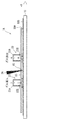
レーザ処理装置1は、図1、2に示すように、平面方向軸(X及びY)を有する試料台10が移動台11A上に設置されて図示左右方向および図示奥行き及び手前方向に移動可能に設置されており、試料台10の上方位置に長尺なレーザ光導入窓15が形成されている。移動台11Aは、図示しない駆動装置により試料台10を移動させるものであり、移動台11Aおよび図示しない駆動装置は本発明の移動装置11を構成する。
なお、本発明のレーザ処理装置1では、後述する基板100を試料台10上に載置している。しかし、本発明では、被処理体を保持できるものであればよく、載置などを行うものに限定されず、把持やガス浮上などによって、被処理体が保持されるものであってもよい。
以下に、本発明の一実施形態のレーザ処理装置1を添付図面に基づいて説明する。
レーザ処理装置1は、図1、2に示すように、平面方向軸(X及びY)を有する試料台10が移動台11A上に設置されて図示左右方向および図示奥行き及び手前方向に移動可能に設置されており、試料台10の上方位置に長尺なレーザ光導入窓15が形成されている。移動台11Aは、図示しない駆動装置により試料台10を移動させるものであり、移動台11Aおよび図示しない駆動装置は本発明の移動装置11を構成する。
なお、本発明のレーザ処理装置1では、後述する基板100を試料台10上に載置している。しかし、本発明では、被処理体を保持できるものであればよく、載置などを行うものに限定されず、把持やガス浮上などによって、被処理体が保持されるものであってもよい。
レーザ光導入窓15には、レーザ光源(図示しない)より出力されて光学系(図示しない)を経てラインビーム形状としたレーザ光2が入射されて、下方側に照射されるように構成されている。
レーザ光2としては、例えば、商品名「Vyper」のエキシマレーザ光で、波長308nm、パルス周波数600Hzのものを用いることができる。ただし、本発明としては、レーザ光の種別は連続波、パルス光のいずれであってもよく、その周波数なども特に限定されるものではなく、複数のレーザ光を用いるものであってもよい。
レーザ光2としては、例えば、商品名「Vyper」のエキシマレーザ光で、波長308nm、パルス周波数600Hzのものを用いることができる。ただし、本発明としては、レーザ光の種別は連続波、パルス光のいずれであってもよく、その周波数なども特に限定されるものではなく、複数のレーザ光を用いるものであってもよい。
レーザ光2は、上記したように、X方向に短軸、Y方向に長軸を有する形状を有しており、例えば、照射面上で短軸幅0.155~0.450mm、長軸幅370~1300mmを例示することができる。この実施形態では、照射面上で短軸幅0.4mm、長軸幅750mm、短軸方向ビームスティープネス70μmのビームとしている。ただし、本発明としては、レーザ光の短軸幅、長軸幅の大きさ等が限定されるものではなく、また、レーザ光のビーム断面形状がラインビームに限定されるものではない。
レーザ光導入窓15は、本発明の透過領域に相当する。レーザ光導入窓15は、レーザ光のビーム断面形状に合わせた長尺形状とされている。レーザ光をそのまま透過させる場合、レーザ光のビーム断面形状よりも大きい長尺幅および短軸幅で形成される。また、レーザ光の短軸と長軸の一方または両方の縁部をレーザ光導入窓15で遮蔽するようにレーザ光導入窓15の形状を定めるものであってもよい。この実施形態では、レーザ光導入窓15の長軸方向の大きさは、透過するレーザ光2のサイズに対し、両側でそれぞれ25mm大きくなっている。
試料台10は、上記したように移動可能であり、X方向に移動することでレーザ光2を相対的に走査しつつレーザ光2を照射することを可能にする。これにより、レーザ光2は、試料台10の移動方向とは逆の方向で基板100に対し走査される。
レーザ光導入窓15には、その周囲に矩形状の整流板20が設けられている。試料台10には、50nm厚の非晶質シリコン半導体薄膜(図示しない)を形成した基板100が設置され、整流板20の下面の整流面20Aは、前記半導体薄膜と間隔を有してX方向に沿って伸張している。その間隔は、1~20mmの間隔を有するのが望ましく、この実施形態では、5mmに設定されている。ただし、本発明としては、その間隔は特に限定されるものではなく、適宜の間隔を設定することも可能である。
半導体薄膜を形成した基板100は、本発明の被処理体に相当する。ただし、本発明としては、被処理体の種別が、半導体薄膜を形成した基板に限定されるものではなく、レーザ光の照射によって適宜の処理を行う全てのものに適用が可能である。
半導体薄膜を形成した基板100は、本発明の被処理体に相当する。ただし、本発明としては、被処理体の種別が、半導体薄膜を形成した基板に限定されるものではなく、レーザ光の照射によって適宜の処理を行う全てのものに適用が可能である。
整流板20は、レーザ光2の長軸幅両端を超える幅を有しており、レーザ光2の長軸両端からそれぞれ20mm以上伸張した幅を有しているのが望ましい。この実施形態では、レーザ光2の長軸端からそれぞれ外側に50mm伸張した幅を有している。
また、整流板20は、レーザ光導入窓15に対し、-X方向側(図示左方側)に離隔した位置で上下に貫通したガス供給孔22Bを有し、+X方向側(図示右方側)に離隔した位置で上下に貫通したガス吸引孔23Bを有している。ガス供給孔22Bおよびガス吸引孔23Bは、照射面上のレーザ光2の断面形状に従って長尺形状を有しており、その長さは、照射面上のレーザ光2の長軸両端を超える長さを有している。さらに、レーザ光導入窓15の長軸両端を超える長さを有している。
また、ガス供給孔22Bおよびガス吸引孔23Bは、照射面上のレーザ光2の近接する短軸端から50mmを超える距離bを有しているのが望ましい。この実施形態では、150mmの距離を有している。
また、整流板20は、レーザ光導入窓15に対し、-X方向側(図示左方側)に離隔した位置で上下に貫通したガス供給孔22Bを有し、+X方向側(図示右方側)に離隔した位置で上下に貫通したガス吸引孔23Bを有している。ガス供給孔22Bおよびガス吸引孔23Bは、照射面上のレーザ光2の断面形状に従って長尺形状を有しており、その長さは、照射面上のレーザ光2の長軸両端を超える長さを有している。さらに、レーザ光導入窓15の長軸両端を超える長さを有している。
また、ガス供給孔22Bおよびガス吸引孔23Bは、照射面上のレーザ光2の近接する短軸端から50mmを超える距離bを有しているのが望ましい。この実施形態では、150mmの距離を有している。
ガス供給孔22Bの上端側は、整流板20の上方に設けられたガス供給筒22Aに連通している。ガス供給筒22Aは、ガス入口を除いて封止されており、ガス入口には図示しないガス供給源に接続されている。ガス供給源では、単一あるいは2種類以上の任意の混合比からなるガスを供給することができ、被処理体の種類や処理の内容に応じてガスを変更できるようにしてもよく、処理の途中でガスの種類を変更できるようにしてもよい。
ガス供給孔22Bにおけるガスの供給流量は、一定量に定めることができ、また、処理中に流量を変更できるようにしてもよい。ガスの供給流量は、例えば50L/minを例示することができる。ガス供給孔22Bとガス供給筒22Aは、ガス供給部22を構成している。
ガス供給孔22Bにおけるガスの供給流量は、一定量に定めることができ、また、処理中に流量を変更できるようにしてもよい。ガスの供給流量は、例えば50L/minを例示することができる。ガス供給孔22Bとガス供給筒22Aは、ガス供給部22を構成している。
ガス吸引孔23Bの上端側は、整流板20の上方に設けられたガス吸引筒23Aに連通している。ガス吸引筒23Aは、ガス出口を除いて封止されており、ガス出口には図示しないガス吸引装置に接続されている。ガス吸引装置では、ガス供給に合わせて動作させることができるが、ガス吸引の開始に合わせることなくガス吸引を行うものであってもよい。
ガス吸引孔23Bとガス吸引筒23Aは、ガス吸引部23を構成している。この実施形態では、ガス吸引部23がガス排出部を構成する。
ガス吸引孔23Bにおけるガスの吸引量は、ガス供給量に合わせて行うのが望ましい。ガスの吸引量をガスの供給量に見合う量にすることで、圧力を維持することができる。さらに、全体雰囲気に対する給気や吸引があれば、これを考慮してガスの供給量とガスの吸引量を定めて、全体における給気と吸引を合わせることができる。
ガス吸引孔23Bとガス吸引筒23Aは、ガス吸引部23を構成している。この実施形態では、ガス吸引部23がガス排出部を構成する。
ガス吸引孔23Bにおけるガスの吸引量は、ガス供給量に合わせて行うのが望ましい。ガスの吸引量をガスの供給量に見合う量にすることで、圧力を維持することができる。さらに、全体雰囲気に対する給気や吸引があれば、これを考慮してガスの供給量とガスの吸引量を定めて、全体における給気と吸引を合わせることができる。
整流板20は、レーザ光導入窓15を基準にしてガス供給孔22Bおよびガス吸引孔23Bよりも外側に伸張しており、整流板20の外側端部は、それぞれガス供給孔22Bおよびガス吸引孔23Bの外側端部から、ガス供給孔22Bおよびガス吸引孔23Bの内側間の距離(a)よりも大きな長さ(>a)を有している。
上記した整流板20、ガス供給部22、ガス吸引部23は、本発明の整流装置を構成する。
上記した整流板20、ガス供給部22、ガス吸引部23は、本発明の整流装置を構成する。
なお、レーザ処理装置1は、図示しない処理室を有し、該処理室内に移動装置11、試料台10および整流装置を有し、処理室の外部にレーザ光の出力源や光学系を位置させたものが例示される。
次に、上記レーザ処理装置1の動作について説明する。
試料台10に被処理体として、非晶質シリコン半導体薄膜を上面に設けた基板100を載置する。
試料台10は、移動装置11によってX-Y方向において初期位置に移動させる。この際に、基板100のY方向における所定の領域が、レーザ光2の照射領域に重なるように、試料台10のY方向の移動位置を決定し、X方向で基板100の先端がレーザ光の照射位置にあるように移動させる。
この状態でガス供給部22では、ガス供給筒22Aに所定のガスを供給し、ガス供給孔22Bから所定のガス流量でガスを供給し、一方、ガス吸引部23では、ガス供給量に合わせてガスの吸引を行う。なお、この実施形態では、ガスとして窒素などの不活性ガスを用いている。ガスの供給と吸引によって、レーザ光2の照射領域では、乱流が生じにくく層流状態になって局部ガス雰囲気が安定する。なお、処理の初期では、吸引孔23Bの下方に試料台10が位置しないため、ガスの吸引力が弱くなるので、処理初期にはガス吸引部23における吸引量を多くするようにしてもよい。
試料台10に被処理体として、非晶質シリコン半導体薄膜を上面に設けた基板100を載置する。
試料台10は、移動装置11によってX-Y方向において初期位置に移動させる。この際に、基板100のY方向における所定の領域が、レーザ光2の照射領域に重なるように、試料台10のY方向の移動位置を決定し、X方向で基板100の先端がレーザ光の照射位置にあるように移動させる。
この状態でガス供給部22では、ガス供給筒22Aに所定のガスを供給し、ガス供給孔22Bから所定のガス流量でガスを供給し、一方、ガス吸引部23では、ガス供給量に合わせてガスの吸引を行う。なお、この実施形態では、ガスとして窒素などの不活性ガスを用いている。ガスの供給と吸引によって、レーザ光2の照射領域では、乱流が生じにくく層流状態になって局部ガス雰囲気が安定する。なお、処理の初期では、吸引孔23Bの下方に試料台10が位置しないため、ガスの吸引力が弱くなるので、処理初期にはガス吸引部23における吸引量を多くするようにしてもよい。
図示しないレーザ光源からは、パルス状に発振されたレーザ光2が光学系を通過して線状となったビーム(ラインビーム)となり、レーザ光導入窓15を通して基板100上の非晶質シリコン半導体膜の照射面上に適宜の照射エネルギー密度(例えば370mJ・cm-2)で照射される。
試料台10は、移動装置11によって、所定の速度で+X方向に移動する。これによりレーザ光2は、相対的に走査されつつ基板100に照射される。
試料台10は、移動装置11によって、所定の速度で+X方向に移動する。これによりレーザ光2は、相対的に走査されつつ基板100に照射される。
また、整流板20では、上記のようにガス供給孔22Bから供給されたガスがガス吸引孔23Bに向けてガスの層流が生じ、安定した局部ガス雰囲気が得られる。さらに、ガス供給孔22Bでは、整流面20Aに沿って外側に流れる層流が形成され、全体雰囲気における大気などが外方から照射領域に流入するのを防止する。さらに、レーザ光照射後も、しばらくの間は、整流面20Aによって良好な局所ガス雰囲気下に置かれるので、レーザアニールの作用が良好に進行して良質に結晶化がなされる。
また、ガス供給孔22Bでは、整流面20Aに沿って両側方にもガス流が流れ、外方から大気などが照射領域に流入するのを防止する。さらに、ガス吸引孔23Bでは、外方からガスが吸引され、全体雰囲気中の浮遊物などを吸引してレーザ光照射前に排除することができる。
また、ガス供給孔22Bでは、整流面20Aに沿って両側方にもガス流が流れ、外方から大気などが照射領域に流入するのを防止する。さらに、ガス吸引孔23Bでは、外方からガスが吸引され、全体雰囲気中の浮遊物などを吸引してレーザ光照射前に排除することができる。
非晶質シリコン半導体膜は、前記レーザ光2のパルスに合わせて移動する試料台10によって、一定の速度で+X方向に移動しながらレーザ光2を照射することによって、レーザ光2が走査されて照射面が移動し、照射面によって非晶質シリコン半導体膜の任意の領域が再結晶化される。また、安定した局所ガス雰囲気によりレーザアニールを良好に行うことができる。
基板100のY方向の所定の領域で処理を完了すると、移動装置11によって試料台10をY方向(図2では+Y方向)に移動させて、Y方向の異なる領域に、同様の処理を行う。この際に、試料台10を一旦、-X方向に移動させて初期位置に復帰させた後、上記と同様の処理を行ってもよく、-X方向に試料台10を移動しつつレーザ光2を照射してもよい。逆方向に移動させる場合、そのままガス供給部22とガス吸引部23を使用してもよく、ガス供給部22とガス吸引部23の配管の切替などによって両者を切り替えて、-X方向において前方にガス吸引部が位置し、後方にガス供給部が位置するようにしてもよい。また、基板100のY方向の所定の領域を処理した後、試料台10を180度回転させて基板100のY方向の異なる領域にレーザ光を照射するようにしてもよい。
なお、この実施形態では、非晶質半導体膜にレーザ光を照射して再結晶化を行ったが、他の目的でレーザ光を照射して処理を行うものに広く適用することができる。
(実施形態2)
次に、他の実施形態を図3に基づいて説明する。なお、上記実施形態と同一の構成については同一の符号を付してその説明を省略または簡略化する。
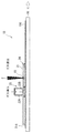
実施形態1では、レーザ光を基板100に対して垂直に照射をしてレーザアニール処理を行ったが、基板100の表面に対し、斜め方向からレーザ光を照射する構成を有するものであってもよい。
図3のレーザ処理装置1Aでは、試料台10のX方向での移動方向に対し、斜め前方に傾けたレーザ光2Aを、レーザ光導入窓15を通して基板100に照射する。この実施形態2においても、安定した局所ガス雰囲気において、レーザアニール処理を行うことができる。
次に、他の実施形態を図3に基づいて説明する。なお、上記実施形態と同一の構成については同一の符号を付してその説明を省略または簡略化する。
実施形態1では、レーザ光を基板100に対して垂直に照射をしてレーザアニール処理を行ったが、基板100の表面に対し、斜め方向からレーザ光を照射する構成を有するものであってもよい。
図3のレーザ処理装置1Aでは、試料台10のX方向での移動方向に対し、斜め前方に傾けたレーザ光2Aを、レーザ光導入窓15を通して基板100に照射する。この実施形態2においても、安定した局所ガス雰囲気において、レーザアニール処理を行うことができる。
(実施形態3)
上記各実施形態では、ガス吸引部を必須の構成として説明したが、ガス吸引部を有していないものとしてもよい。この実施形態3を図4に基づいて説明する。なお、上記実施形態と同一の構成については同一の符号を付してその説明を省略または簡略化する。
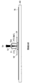
この実施形態のレーザ処理装置1Bでは、ガス排出側の長さを短くした整流板21がレーザ光導入窓15の周縁に設けられている。
上記各実施形態では、ガス吸引部を必須の構成として説明したが、ガス吸引部を有していないものとしてもよい。この実施形態3を図4に基づいて説明する。なお、上記実施形態と同一の構成については同一の符号を付してその説明を省略または簡略化する。
この実施形態のレーザ処理装置1Bでは、ガス排出側の長さを短くした整流板21がレーザ光導入窓15の周縁に設けられている。
整流板21の下面の整流面21Aは、前記実施形態と同様に、基板100との間の間隔が5mmに設定されている。また、整流板21は、レーザ光2の長軸幅両端を超える幅を有しており、レーザ光2の長軸端から50mm以上外側に伸張した幅を有している。
ガス供給孔22Bは、照射面上のレーザ光2の断面形状に従って長尺形状を有しており、その長さは、照射面上のレーザ光2の長軸両端を超える長さを有している。ガス供給孔22Bは照射面上のレーザ光2の近接する短軸端から250mmの距離を有しており、他側側では、整流板21における長さは、照射面上のレーザ光2の近接する短軸端から250mmとなっている。整流板21における他側側の端部は、ガスが排出されるガス排出部24を構成している。
ガス供給孔22Bは、照射面上のレーザ光2の断面形状に従って長尺形状を有しており、その長さは、照射面上のレーザ光2の長軸両端を超える長さを有している。ガス供給孔22Bは照射面上のレーザ光2の近接する短軸端から250mmの距離を有しており、他側側では、整流板21における長さは、照射面上のレーザ光2の近接する短軸端から250mmとなっている。整流板21における他側側の端部は、ガスが排出されるガス排出部24を構成している。
ガス供給孔22Bは、整流板21の上方に設けられたガス供給筒22Aに連通している。
整流板21は、レーザ光導入窓15を基準にしてガス供給孔22Bよりも外側に伸張しており、整流板21の外側端部は、ガス供給孔22Bの外側端部から、ガス供給孔22Bから他側側の整流板21の端部までの距離よりも大きな長さを有している。
上記した整流板21、ガス供給部22は、本発明の整流装置を構成する。
整流板21は、レーザ光導入窓15を基準にしてガス供給孔22Bよりも外側に伸張しており、整流板21の外側端部は、ガス供給孔22Bの外側端部から、ガス供給孔22Bから他側側の整流板21の端部までの距離よりも大きな長さを有している。
上記した整流板21、ガス供給部22は、本発明の整流装置を構成する。
この実施形態においても、ガス供給部22から供給されたガスは、整流面21Aと基板100との間を通ってガス排出部24側に移動して層流となり、安定した局所ガス雰囲気を形成して良好なアニール処理を可能にする。さらに、ガス供給部22によるガス供給位置よりも外側で、外側に向けた層流が生じ、外部の全体雰囲気からのガスなどの流入が防止される。
(実施形態4)
上記各実施形態では、ガス供給を基板100の上方から下方側に垂直に向けて供給し、ガス吸引を行う場合は、直上に吸引を行うものについて説明したが、基板100に対し斜め方向からガスを供給し、ガス吸引を行う場合は、斜め方向に吸引するようにしてもよい。
この実施形態のレーザ処理装置1Cを図5に基づいて説明する。なお、上記実施形態と同一の構成については同一の符号を付してその説明を省略または簡略化する。
上記各実施形態では、ガス供給を基板100の上方から下方側に垂直に向けて供給し、ガス吸引を行う場合は、直上に吸引を行うものについて説明したが、基板100に対し斜め方向からガスを供給し、ガス吸引を行う場合は、斜め方向に吸引するようにしてもよい。
この実施形態のレーザ処理装置1Cを図5に基づいて説明する。なお、上記実施形態と同一の構成については同一の符号を付してその説明を省略または簡略化する。
レーザ処理装置1Cでは、試料台10の上方側に長尺なレーザ光導入窓16が形成されている。レーザ光導入窓16は、本発明の透過領域に相当する。
レーザ光導入窓16は、レーザ光のビーム断面形状に合わせた長尺形状とされている。 レーザ光導入窓16は、その周囲に矩形状の整流板30が設けられている。整流板30の下面の整流面30Aは、前記非晶質シリコン半導体膜と5mmの間隔を有してX方向に沿って伸張している。
レーザ光導入窓16は、レーザ光のビーム断面形状に合わせた長尺形状とされている。 レーザ光導入窓16は、その周囲に矩形状の整流板30が設けられている。整流板30の下面の整流面30Aは、前記非晶質シリコン半導体膜と5mmの間隔を有してX方向に沿って伸張している。
整流板30は、レーザ光2の長軸幅両端を超える幅を有しており、レーザ光2の長軸端から外側に50mm伸張した幅を有している。
また、整流板30は、レーザ光導入窓16に対し、-X方向側(図示左方側)に離隔して上下に貫通したガス供給孔22Cを有し、+X方向側(図示右方側)に離隔して上下に貫通したガス吸引孔23Cを有している。ガス供給孔22Cおよびガス吸引孔23Cは、照射面上のレーザ光2の断面形状に従って長尺形状を有しており、その長さは、照射面上のレーザ光2の長軸両端を超える長さを有している。
また、整流板30は、レーザ光導入窓16に対し、-X方向側(図示左方側)に離隔して上下に貫通したガス供給孔22Cを有し、+X方向側(図示右方側)に離隔して上下に貫通したガス吸引孔23Cを有している。ガス供給孔22Cおよびガス吸引孔23Cは、照射面上のレーザ光2の断面形状に従って長尺形状を有しており、その長さは、照射面上のレーザ光2の長軸両端を超える長さを有している。
ガス供給孔22Cおよびガス吸引孔23Cは、下端側の位置で、照射面上のレーザ光2の近接する短軸端から150mmを超える距離を有しているのが望ましい。この実施形態では、250mmの距離を有している。
ガス供給孔22Cは、下方側がレーザ光導入窓16側に近づくように傾斜した角度を有しており、整流板30の鉛直方向に対する角度θ1として0超~60度の角度を有しているのが望ましい。
また、ガス吸引孔23Cは、下方側がレーザ光導入窓16側に近づくように傾斜した角度を有しており、整流板30の鉛直方向に対する角度θ2として0超~60度の角度を有しているのが望ましい。
ガス供給孔22Cは、下方側がレーザ光導入窓16側に近づくように傾斜した角度を有しており、整流板30の鉛直方向に対する角度θ1として0超~60度の角度を有しているのが望ましい。
また、ガス吸引孔23Cは、下方側がレーザ光導入窓16側に近づくように傾斜した角度を有しており、整流板30の鉛直方向に対する角度θ2として0超~60度の角度を有しているのが望ましい。
ガス供給孔22Cは、整流板30の上方に設けられたガス供給筒22Aに連通しており、ガス供給孔22Cとガス供給筒22Aは、ガス供給部22を構成している。
ガス吸引孔23Cは、整流板30の上方に設けられたガス吸引筒23Aに連通しており、ガス吸引孔23Cとガス吸引筒23Aは、ガス吸引部23を構成している。
ガス吸引孔23Cは、整流板30の上方に設けられたガス吸引筒23Aに連通しており、ガス吸引孔23Cとガス吸引筒23Aは、ガス吸引部23を構成している。
整流板30は、レーザ光導入窓16を基準にしてガス供給孔22Cおよびガス吸引孔23Cよりも外側に伸張しており、整流板30の外側端部は、それぞれガス供給孔22Cおよびガス吸引孔23Cの外側端部から、ガス供給孔22Cおよびガス吸引孔23Cの内側間の距離よりも大きな長さを有している。
上記した整流板30、ガス供給部22、ガス吸引部23は、本発明の整流装置を構成する。
上記した整流板30、ガス供給部22、ガス吸引部23は、本発明の整流装置を構成する。
この実施形態では、ガス供給孔22Cによってガスが斜め前方方向に導入され、整流面30Aとガラス基板100との間で、より円滑に層流が形成される。
また、層流となったガスは、ガス吸引孔23Cによって斜め上方側に吸引され、整流面30Aとガラス基板100との間のガスが円滑に排出される効果がある。
また、層流となったガスは、ガス吸引孔23Cによって斜め上方側に吸引され、整流面30Aとガラス基板100との間のガスが円滑に排出される効果がある。
以上、本発明について上記実施形態に基づいて説明を行ったが、本発明は上記実施形態の内容に限定されるものではなく、本発明の範囲を逸脱しない限りは上記実施形態に対する適宜の変更が可能である。
本願は、2015年10月26日に出願された日本国特許出願第2015-209516号の優先権の利益を主張し、この出願に記載された全ての内容を援用するものとする。
1 レーザ処理装置
1A レーザ処理装置
1B レーザ処理装置
1C レーザ処理装置
2 レーザ光
3 レーザ光
10 試料台
11A 移動台
11 移動装置
20 整流板
20A 整流面
21 整流板
21A 整流面
22 ガス供給部
22A ガス供給筒
22B ガス供給孔
22C ガス供給孔
23 ガス吸引部
23A ガス吸引筒
23B ガス吸引孔
23C ガス吸引孔
24 ガス排出部
30 整流板
30A 整流面
1A レーザ処理装置
1B レーザ処理装置
1C レーザ処理装置
2 レーザ光
3 レーザ光
10 試料台
11A 移動台
11 移動装置
20 整流板
20A 整流面
21 整流板
21A 整流面
22 ガス供給部
22A ガス供給筒
22B ガス供給孔
22C ガス供給孔
23 ガス吸引部
23A ガス吸引筒
23B ガス吸引孔
23C ガス吸引孔
24 ガス排出部
30 整流板
30A 整流面
Claims (20)
- 板面を有する被処理体にレーザ光を照射して処理を行うレーザ処理装置に設けられる整流装置であって、
レーザ光が透過して、前記レーザ処理装置に保持された前記被処理体に照射される透過領域の端部側に設置され、前記被処理体と間隔を置いて、前記被処理体の板面に沿って前記透過領域の外方に伸張する整流面を有する整流部と、
前記透過領域に設置された状態で前記透過領域から離隔した位置で前記整流面の一側側と前記透過領域との間の空隙にガスを供給するガス供給部と、
前記透過領域に設置された状態で前記透過領域から離隔した位置で、前記一側側と前記透過領域を挟む他側側で、前記整流面と前記被処理体の間の空隙にあるガスを前記空隙の外に排出するガス排出部と、を有することを特徴とするレーザ処理装置整流装置。 - 前記整流部は、前記透過領域周縁全体に対し外方に伸張する形状を有していることを特徴とする請求項1記載のレーザ処理装置整流装置。
- 前記整流部は、前記整流面が前記透過領域を基準にして前記ガス排出部の外側に伸張する大きさを有しており、前記ガス排出部は、前記空隙からガスを吸引するガス吸引部を有することを特徴とする請求項1または2に記載のレーザ処理装置整流装置。
- 板面を有する被処理体にレーザ光を照射して処理を行うレーザ処理装置において、
前記レーザ光が透過して該レーザ処理装置に保持された前記被処理体に照射される透過領域と、
前記透過領域の端部側から、前記被処理体と間隔を置いて前記被処理体の板面に沿って前記透過領域外方に伸張する整流面を有する整流部と、
前記透過領域から離隔した位置で前記整流面の一側側と前記透過領域との間の空隙にガスを供給するガス供給部と、
前記透過領域から離隔した位置で、前記一側側と前記透過領域を挟む他側側で前記整流面と前記被処理体の間の空隙にあるガスを前記空隙の外に排出するガス排出部と、を有することを特徴とするレーザ処理装置。 - 前記レーザ光が、前記被処理体上でラインビームの形状を有し、かつ前記透過領域が前記ラインビーム形状の短軸方向および長軸方向に合わせて、それぞれ短軸と長軸を有する長尺形状を有しており、
前記整流部は、前記整流面が前記透過領域の短軸側両側および長軸側両側で前記透過領域の外方に伸張していることを特徴とする請求項4記載のレーザ処理装置。 - 前記整流面は、前記透過領域の長軸端部側においてレーザ光の長軸端部から長軸方向で外側に20mm以上伸張していることを特徴とする請求項4または5に記載のレーザ処理装置。
- 前記ガス供給部と前記ガス排出部が、ガスの供給および排出によって生じるガス流が、前記レーザ光が前記被処理体に照射される照射領域を覆うように設けられていることを特徴とする請求項4~6のいずれかに記載のレーザ処理装置。
- 前記レーザ光が、前記被処理体上でラインビームの形状を有し、かつ前記透過領域が前記ラインビーム形状の短軸方向および長軸方向に合わせて、それぞれ短軸と長軸を有する長尺形状を有しており、
前記ガス供給部と前記ガス排出部とが、前記透過領域を挟んで、それぞれ照射面上のレーザ光の長軸幅の両端を超える長さ範囲でガスの供給および排出を行うことを特徴とする請求項7記載のレーザ処理装置。 - 前記整流部は、前記透過領域を基準にして、前記一側側で前記ガス供給部によるガス供給位置の外側にさらに前記整流面が伸張し、前記他側側で前記ガス排出部まで整流面が伸張していることを特徴とする請求項4~8のいずれか1項に記載のレーザ処理装置。
- 前記整流部は、前記整流面が前記透過領域を基準にして、前記ガス排出部によるガス排出位置の外側に伸張しており、前記ガス排出部は、前記空隙からガスを吸引するガス吸引部を有することを特徴とする請求項4~9のいずれか1項に記載のレーザ処理装置。
- 前記ガス吸引部は、前記空隙に連通し、前記整流面と垂直な方向と前記ガス排出部の外側方向と間の方向にガスが流れるガス排出路を有していることを特徴とする請求項10に記載のレーザ処理装置。
- 前記整流面は、前記ガス供給部によるガス供給位置の外側に伸張している長さが、前記ガス供給位置と前記ガス排出位置との間の間隔よりも大きいことを特徴とする請求項10または11に記載のレーザ処理装置。
- 前記整流面は、前記ガス排出部によるガス排出位置の外側に伸張している長さが、前記ガス供給位置と前記ガス排出位置との間の間隔よりも大きいことを特徴とする請求項12に記載のレーザ処理装置。
- 前記ガス供給部は、前記空隙に連通し、前記整流面と垂直な方向と前記ガス供給部の内側方向と間の方向にガスが流れるガス供給路を有していることを特徴とする請求項4~13のいずれか1項に記載のレーザ処理装置。
- 前記被処理体の移動を行う移動装置を有し、
前記移動の方向を基準にして、移動方向後方側に前記ガス供給部によるガス供給位置を有し、移動方向前方側に前記ガス排出部によるガス排出位置を有していることを特徴とする請求項4~14のいずれか1項に記載のレーザ処理装置。 - 前記移動装置が往復動可能になっており、移動方向に従って前記ガス供給部と前記ガス排出部の切替えが可能になっていることを特徴とする請求項15に記載のレーザ処理装置。
- 前記ガス供給部によるガス供給位置が、照射位置における前記レーザ光の近接する端部側と50mm以上の距離を有していることを特徴とする請求項4~16のいずれか1項に記載のレーザ処理装置。
- 前記ガス排出部によるガス排出位置が、照射位置における前記レーザ光の近接する端部側と150mm以上の距離を有していることを特徴とする請求項4~17のいずれか1項に記載のレーザ処理装置。
- 前記整流面と前記被処理体の板面との間隔が1~20mmの範囲内にあることを特徴とする請求項4~18のいずれか1項に記載のレーザ処理装置。
- 前記被処理体に非単結晶半導体層を有し、前記レーザ光による処理が再結晶化であることを特徴とする請求項4~19のいずれか1項に記載のレーザ処理装置。
Priority Applications (2)
| Application Number | Priority Date | Filing Date | Title |
|---|---|---|---|
| CN201680062525.5A CN108349044A (zh) | 2015-10-26 | 2016-10-25 | 激光处理装置整流装置及激光处理装置 |
| US15/769,721 US11355364B2 (en) | 2015-10-26 | 2016-10-25 | Laser treatment device rectifier device and laser treatment device |
Applications Claiming Priority (2)
| Application Number | Priority Date | Filing Date | Title |
|---|---|---|---|
| JP2015209516A JP6124425B1 (ja) | 2015-10-26 | 2015-10-26 | レーザ処理装置整流装置およびレーザ処理装置 |
| JP2015-209516 | 2015-10-26 |
Publications (1)
| Publication Number | Publication Date |
|---|---|
| WO2017073561A1 true WO2017073561A1 (ja) | 2017-05-04 |
Family
ID=58631708
Family Applications (1)
| Application Number | Title | Priority Date | Filing Date |
|---|---|---|---|
| PCT/JP2016/081580 Ceased WO2017073561A1 (ja) | 2015-10-26 | 2016-10-25 | レーザ処理装置整流装置およびレーザ処理装置 |
Country Status (5)
| Country | Link |
|---|---|
| US (1) | US11355364B2 (ja) |
| JP (1) | JP6124425B1 (ja) |
| CN (1) | CN108349044A (ja) |
| TW (1) | TWI695750B (ja) |
| WO (1) | WO2017073561A1 (ja) |
Cited By (1)
| Publication number | Priority date | Publication date | Assignee | Title |
|---|---|---|---|---|
| JP2020179407A (ja) * | 2019-04-25 | 2020-11-05 | 株式会社タマリ工業 | ノズル及びそのノズルを用いたレーザ加工装置 |
Families Citing this family (8)
| Publication number | Priority date | Publication date | Assignee | Title |
|---|---|---|---|---|
| KR102379215B1 (ko) * | 2017-10-31 | 2022-03-28 | 삼성디스플레이 주식회사 | 레이저 장치 |
| WO2020003421A1 (ja) * | 2018-06-27 | 2020-01-02 | ギガフォトン株式会社 | レーザ加工装置、レーザ加工システム、及びレーザ加工方法 |
| JP6852031B2 (ja) * | 2018-09-26 | 2021-03-31 | 株式会社東芝 | 溶接装置及びノズル装置 |
| DE102019103659B4 (de) * | 2019-02-13 | 2023-11-30 | Bystronic Laser Ag | Gasführung, Laserschneidkopf und Laserschneidmaschine |
| JP7306860B2 (ja) * | 2019-04-11 | 2023-07-11 | Jswアクティナシステム株式会社 | レーザ処理装置 |
| JP7014209B2 (ja) * | 2019-07-18 | 2022-02-01 | 株式会社豊田中央研究所 | 加工用治具、レーザ加工用装置、およびレーザ加工製品の製造方法 |
| WO2021065063A1 (ja) * | 2019-10-03 | 2021-04-08 | 三菱電機株式会社 | 溶接装置および溶接方法 |
| CN115958290A (zh) * | 2023-01-20 | 2023-04-14 | 通快(中国)有限公司 | 用于激光焊接的气体辅助装置和激光焊接系统 |
Citations (8)
| Publication number | Priority date | Publication date | Assignee | Title |
|---|---|---|---|---|
| JPS52114491U (ja) * | 1976-02-27 | 1977-08-31 | ||
| JPH01261292A (ja) * | 1988-04-13 | 1989-10-18 | Agency Of Ind Science & Technol | 半導体単結晶膜の製造方法 |
| JPH07503904A (ja) * | 1992-02-25 | 1995-04-27 | アルテック・エス・アール・エル | レーザ加工装置 |
| JP2002009435A (ja) * | 2000-06-20 | 2002-01-11 | Sumitomo Heavy Ind Ltd | 有機物基板におけるビア処理方法及びビア形成方法 |
| JP2002178174A (ja) * | 2000-12-12 | 2002-06-25 | Daido Steel Co Ltd | バットマーキング方法およびバットマーキング装置 |
| JP2002210582A (ja) * | 2001-01-19 | 2002-07-30 | Ricoh Microelectronics Co Ltd | ビーム加工装置 |
| US20040238504A1 (en) * | 2001-07-05 | 2004-12-02 | Pascal Aubry | Welding unit with miniaturised laser beam |
| JP2016087639A (ja) * | 2014-11-04 | 2016-05-23 | 株式会社ディスコ | レーザー加工装置 |
Family Cites Families (16)
| Publication number | Priority date | Publication date | Assignee | Title |
|---|---|---|---|---|
| IT1119679B (it) * | 1979-03-05 | 1986-03-10 | Fiat Auto Spa | Apparecchiatura per effettuare trattamenti su pezzi metallici mediante |
| US5293023A (en) * | 1992-03-13 | 1994-03-08 | Mitsui Petrochemical Industries, Ltd. | Laser irradiation nozzle and laser apparatus using the same |
| US6535535B1 (en) * | 1999-02-12 | 2003-03-18 | Semiconductor Energy Laboratory Co., Ltd. | Laser irradiation method, laser irradiation apparatus, and semiconductor device |
| JP2001118783A (ja) * | 1999-10-21 | 2001-04-27 | Nikon Corp | 露光方法及び装置、並びにデバイス製造方法 |
| KR100673073B1 (ko) * | 2000-10-21 | 2007-01-22 | 삼성전자주식회사 | 레이저 빔을 이용한 비금속 기판의 절단 방법 및 장치 |
| JP4845267B2 (ja) | 2001-01-15 | 2011-12-28 | 東芝モバイルディスプレイ株式会社 | レーザアニール装置およびレーザアニール方法 |
| JP3859543B2 (ja) * | 2002-05-22 | 2006-12-20 | レーザーフロントテクノロジーズ株式会社 | レーザ加工装置 |
| JP4459514B2 (ja) * | 2002-09-05 | 2010-04-28 | 株式会社半導体エネルギー研究所 | レーザーマーキング装置 |
| NL1022231C2 (nl) * | 2002-12-20 | 2004-06-22 | Fico Bv | Werkwijze en inrichting voor het met een laserstraal bewerken van een drager voor ten minste één elektronische component. |
| JP4130790B2 (ja) * | 2003-08-29 | 2008-08-06 | 住友重機械工業株式会社 | レーザ加工機 |
| JP4404085B2 (ja) * | 2006-11-02 | 2010-01-27 | ソニー株式会社 | レーザ加工装置、レーザ加工ヘッド及びレーザ加工方法 |
| US8057601B2 (en) * | 2007-05-09 | 2011-11-15 | Applied Materials, Inc. | Apparatus and method for supporting, positioning and rotating a substrate in a processing chamber |
| JP5540476B2 (ja) | 2008-06-30 | 2014-07-02 | 株式会社Ihi | レーザアニール装置 |
| US8986497B2 (en) * | 2009-12-07 | 2015-03-24 | Ipg Photonics Corporation | Laser lift off systems and methods |
| JP6222903B2 (ja) * | 2012-08-17 | 2017-11-01 | 株式会社ディスコ | レーザ加工装置 |
| WO2015038309A1 (en) * | 2013-09-16 | 2015-03-19 | Applied Materials, Inc. | Method of forming strain-relaxed buffer layers |
-
2015
- 2015-10-26 JP JP2015209516A patent/JP6124425B1/ja active Active
-
2016
- 2016-10-25 TW TW105134368A patent/TWI695750B/zh active
- 2016-10-25 WO PCT/JP2016/081580 patent/WO2017073561A1/ja not_active Ceased
- 2016-10-25 US US15/769,721 patent/US11355364B2/en active Active
- 2016-10-25 CN CN201680062525.5A patent/CN108349044A/zh active Pending
Patent Citations (8)
| Publication number | Priority date | Publication date | Assignee | Title |
|---|---|---|---|---|
| JPS52114491U (ja) * | 1976-02-27 | 1977-08-31 | ||
| JPH01261292A (ja) * | 1988-04-13 | 1989-10-18 | Agency Of Ind Science & Technol | 半導体単結晶膜の製造方法 |
| JPH07503904A (ja) * | 1992-02-25 | 1995-04-27 | アルテック・エス・アール・エル | レーザ加工装置 |
| JP2002009435A (ja) * | 2000-06-20 | 2002-01-11 | Sumitomo Heavy Ind Ltd | 有機物基板におけるビア処理方法及びビア形成方法 |
| JP2002178174A (ja) * | 2000-12-12 | 2002-06-25 | Daido Steel Co Ltd | バットマーキング方法およびバットマーキング装置 |
| JP2002210582A (ja) * | 2001-01-19 | 2002-07-30 | Ricoh Microelectronics Co Ltd | ビーム加工装置 |
| US20040238504A1 (en) * | 2001-07-05 | 2004-12-02 | Pascal Aubry | Welding unit with miniaturised laser beam |
| JP2016087639A (ja) * | 2014-11-04 | 2016-05-23 | 株式会社ディスコ | レーザー加工装置 |
Cited By (2)
| Publication number | Priority date | Publication date | Assignee | Title |
|---|---|---|---|---|
| JP2020179407A (ja) * | 2019-04-25 | 2020-11-05 | 株式会社タマリ工業 | ノズル及びそのノズルを用いたレーザ加工装置 |
| JP7330449B2 (ja) | 2019-04-25 | 2023-08-22 | 株式会社タマリ工業 | ノズル及びそのノズルを用いたレーザ加工装置 |
Also Published As
| Publication number | Publication date |
|---|---|
| JP2017080754A (ja) | 2017-05-18 |
| US20180315627A1 (en) | 2018-11-01 |
| US11355364B2 (en) | 2022-06-07 |
| TWI695750B (zh) | 2020-06-11 |
| TW201726288A (zh) | 2017-08-01 |
| JP6124425B1 (ja) | 2017-05-10 |
| CN108349044A (zh) | 2018-07-31 |
Similar Documents
| Publication | Publication Date | Title |
|---|---|---|
| JP6124425B1 (ja) | レーザ処理装置整流装置およびレーザ処理装置 | |
| US20240261893A1 (en) | Method for laser processing a transparent material | |
| CN104703933B (zh) | 切割装置 | |
| TWI477340B (zh) | Laser processing methods, laser processing and laser processing equipment | |
| WO2018074283A1 (ja) | レーザ処理装置およびレーザ処理方法 | |
| JP5717146B2 (ja) | レーザラインビーム改善装置およびレーザ処理装置 | |
| CN101001729A (zh) | 基板的垂直裂纹形成方法及垂直裂纹形成装置 | |
| CN113013073A (zh) | 气氛形成装置及上浮搬运方法 | |
| TW201600436A (zh) | 非接觸之用於抓取基板之裝置 | |
| TWI413564B (zh) | 切割基板的設備和使用其切割基板的方法 | |
| TW201706221A (zh) | 疊層基板之加工方法及利用雷射光之疊層基板之加工裝置 | |
| CN104972225A (zh) | 激光加工装置 | |
| JP5408678B2 (ja) | レーザ処理装置 | |
| CN105144344B (zh) | 激光遮挡构件、激光处理装置及激光照射方法 | |
| TW201939593A (zh) | 被加工物的雷射加工方法 | |
| JP2009099917A (ja) | レーザーアニール装置 | |
| KR102472644B1 (ko) | 취성 재료 기판의 분단 방법 그리고 분단 장치 | |
| CN107039260A (zh) | 晶片的加工方法 | |
| TW201313373A (zh) | 刀具頭 | |
| KR101183511B1 (ko) | 레이저 처리 장치 | |
| JP2018052814A (ja) | 脆性材料基板の改質層形成方法並びに改質層形成装置 | |
| JP5261532B2 (ja) | レーザスクライブ方法及びレーザ加工装置 | |
| JP6269876B2 (ja) | 割断装置 |
Legal Events
| Date | Code | Title | Description |
|---|---|---|---|
| 121 | Ep: the epo has been informed by wipo that ep was designated in this application |
Ref document number: 16859791 Country of ref document: EP Kind code of ref document: A1 |
|
| WWE | Wipo information: entry into national phase |
Ref document number: 15769721 Country of ref document: US |
|
| NENP | Non-entry into the national phase |
Ref country code: DE |
|
| 122 | Ep: pct application non-entry in european phase |
Ref document number: 16859791 Country of ref document: EP Kind code of ref document: A1 |