WO2017073454A1 - 医療用拡張器具 - Google Patents
医療用拡張器具 Download PDFInfo
- Publication number
- WO2017073454A1 WO2017073454A1 PCT/JP2016/081120 JP2016081120W WO2017073454A1 WO 2017073454 A1 WO2017073454 A1 WO 2017073454A1 JP 2016081120 W JP2016081120 W JP 2016081120W WO 2017073454 A1 WO2017073454 A1 WO 2017073454A1
- Authority
- WO
- WIPO (PCT)
- Prior art keywords
- dilator
- slider
- puncture needle
- tip
- case body
- Prior art date
- Legal status (The legal status is an assumption and is not a legal conclusion. Google has not performed a legal analysis and makes no representation as to the accuracy of the status listed.)
- Ceased
Links
Images


Classifications
-
- A—HUMAN NECESSITIES
- A61—MEDICAL OR VETERINARY SCIENCE; HYGIENE
- A61B—DIAGNOSIS; SURGERY; IDENTIFICATION
- A61B17/00—Surgical instruments, devices or methods
- A61B17/34—Trocars; Puncturing needles
Definitions
- the present invention relates to a medical expansion device that opens a puncture hole in a body wall and expands the puncture hole in order to insert another medical device from the puncture hole into a body cavity.
- gastrostomy has been performed as needed instead of nasal nutrition.
- This is a method of injecting nutrients directly from the catheter into the stomach through a gastrostomy, which is a hole formed between the abdominal wall and the stomach cavity.
- a gastrostomy which is a hole formed between the abdominal wall and the stomach cavity.
- the abdominal wall and the stomach wall are previously fixed with a suture thread, and a fistula (puncture hole) is opened in the abdominal wall and the stomach wall using a puncture needle, and this fistula is called a dilator.
- the catheter is inserted and placed after expansion using a medical expansion device.
- a medical dilator having a large diameter body portion is known.
- a cannula needle is configured by connecting the needle body and the guide portion, and a dilator is configured by connecting the guide portion and the body portion.
- a rod-shaped member having an obtuse tip, a puncture needle through which the rod-shaped member can be inserted a dilator that can be inserted through the puncture needle and has a tapered tapered tip
- a medical dilator comprising a sheath that allows the dilator to be inserted is also known.
- Such a medical dilator has a projecting / adjusting portion for projecting and retracting the rod-shaped member from the distal end portion of the puncture needle at the distal end portion of the rod-shaped member depending on the presence or absence of the urging force generated toward the proximal end side. It was.
- a mechanism for causing the catheter to protrude and retract from a housing, or a tissue sample inserted into a patient's body in the biopsy needle device for obtaining the above, a mechanism for allowing a cannula and a stylet to appear and disappear from a housing is also known.
- Patent Documents 3 and 4. Although these mechanisms seem to be similar to the protrusion / recess adjuster, they are technical fields different from those of the dilator, and have nothing to do with the configuration for expanding the puncture hole.
- the present invention has been made paying attention to the problems of the prior art as described above, and it is possible to easily perform an operation of opening a puncture hole and expanding the puncture hole, thereby improving usability.
- the purpose is to provide.
- a medical expansion device that opens a puncture hole in a body wall and expands the puncture hole in order to insert another medical device from the puncture hole into a body cavity
- a hollow puncture needle through which a guide wire can be inserted in the axial direction
- a cylindrical dilator that extends coaxially with the puncture needle and through which the puncture needle can be inserted, and supports the puncture needle and the dilator
- a case body The dilator is fixed in a state where the base end portion communicates with the inner cavity of the case body on the front side of the case body, and the distal end portion is formed in a tapered shape that gradually decreases in diameter toward the tip,
- the base end portion extends from the base end portion of the dilator to the lumen of the case body, and the puncture needle is inserted in the lumen
- the operation unit includes a knock rod that is coupled to the slider and protrudes from a rear side of the case body to perform a pushing operation.
- the locking portion is provided on the slider, and a locking claw that protrudes elastically toward the inner wall of the case body, and is provided on the case body, and the slider is punctured by a pushing operation of the knock rod.
- the unlocking portion is provided at a position of the case body facing the locked hole from the outside, and is elastically deformed so as to be fitted into the locked hole and release the snap fit engagement of the locking claw.
- a push button capable of supporting, and a biasing means for biasing the slider in a direction in which the tip of the puncture needle is immersed,
- the slider moves to a position where the tip of the puncture needle protrudes, where the locking claw is the locked hole.
- the push button is pressed, the snap fit engagement is released, and the slider is pulled back to the position where the tip of the puncture needle is retracted by the biasing force of the biasing means.
- a hollow puncture needle that can be inserted through the guide wire in the axial direction, a cylindrical first dilator that extends coaxially with the puncture needle and that can be inserted into the puncture needle, and coaxial with the first dilator
- a cylindrical second dilator that extends through the first dilator and can be inserted through the first dilator, and a case body that supports the puncture needle and the dilator, respectively.
- the second dilator is fixed in a state where the base end portion communicates with the inner cavity of the case body on the front side of the case body, and the distal end portion is formed in a tapered shape that gradually decreases in diameter toward the front.
- the first dilator is inserted into the second dilator and the base end portion extends from the base end portion of the second dilator to the inner cavity of the case body.
- the base end portion extends from the base end portion of the first dilator to the lumen of the case body, and the lumen of the case body Is fixed to a second slider which is arranged so as to be movable in the axial direction of the puncture needle, and the tip part protrudes and appears from the tip part of the first dilator as the second slider moves,
- a first lock portion that holds the tip portion of the first dilator in a protruding position; a second lock portion that holds the second slider in a position where the tip portion of the puncture needle protrudes; and the second lock portion.
- a second unlocking portion that releases the holding by the second position and returns the second slider to a position where the tip of the puncture needle is retracted, and that the holding by the second locking portion is released by the second unlocking portion.
- the first slider is disposed on the front side (distal side) and the second slider is disposed on the rear side (proximal end side) in the lumen of the case body.
- the first slider is provided with a through hole through which the puncture needle fixed to the second slider is inserted and guided to the inside of the first dilator fixed to the first slider.
- the operation part is connected to the second slider, and has a knock rod that protrudes from the rear side of the case body and allows a series of pushing operations.
- the first lock portion is provided on the first slider, and is provided with a first locking claw that elastically protrudes toward the inner wall of the case body, and is provided on the case body to push the knock rod.
- the second lock portion is provided on the second slider, and is provided with a second locking claw that protrudes elastically toward the inner wall of the case body.
- the second lock portion is provided on the case body and is operated to push the knock rod.
- the first unlocking portion is provided at a position of the case body so as to face the first locked hole from the outside, and is fitted into the first locked hole to engage the snap fitting of the first locking claw.
- a first push button that can be elastically deformed so as to release the engagement, and a first urging means that urges the first slider in a direction in which a tip portion of the first dilator is immersed,
- the second unlocking portion is provided at a position of the case body so as to face the second locked hole from the outside, and is fitted into the second locked hole to engage the snap fitting of the second locking claw.
- a second push button that can be elastically deformed so as to release the engagement, and a second urging means that urges the second slider in a direction in which the tip of the puncture needle is retracted,
- the second slider moves to a position where the tip of the puncture needle protrudes, and at the position, the second locking claw is moved. Is held in a snap-fit engagement with the second locked hole, and the first slider is pushed by the second slider and moves to a position where the tip of the first dilator protrudes.
- the first locking claw is snap-engaged and held in the first locked hole
- the second push button By pressing the second push button, the snap fit engagement between the second locking claw and the second locked hole is released, and the second slider is moved by the biasing force of the second biasing means.
- the tip of the puncture needle is pulled back to the position where it is retracted, and then the first push button is pressed to release the snap fit engagement between the first locking claw and the first locked hole,
- the medical expansion instrument according to [3], wherein the first slider is set so as to be pulled back to a position where the tip of the first dilator is retracted by the biasing force of the first biasing means. .
- the medical expansion instrument (10A) described in [1] is used, the medical expansion instrument (10A) is inserted into the inside of the tip of the dilator (40) that is fixed to the front side of the case body (11) and extends in the axial direction. The distal end portion of the puncture needle (20) is projected to the outside.
- the puncture needle (20) is inserted into the inside of the dilator (40), and the base end portion extends to the lumen of the case body (11).
- the puncture needle (20) is fixed to a slider (17) arranged to be movable in the axial direction (front-rear direction). Therefore, as the slider (17) moves back and forth, the puncture needle (20) appears and disappears from the tip of the dilator (30) fixed in place.
- the case body (11) has an operation part (50), and the operation part (50) can move the slider (17) in a direction in which the tip of the puncture needle (20) protrudes to the outside. Further, the case body (11) has a lock portion (70), and the lock portion (70) holds the slider (17) in a position where the tip of the puncture needle (20) protrudes to the outside. Can do.
- the body wall is punctured with the puncture needle (20) protruding outside from the tip of the dilator (40).
- the puncture needle (20) is projected and pushed forward to expand the puncture hole with the subsequent dilator (30)
- the tip of the puncture needle (20) may damage the body cavity. . Therefore, when the tip of the dilator (40) reaches the puncture hole, the puncture needle (20) may be retracted from the tip of the dilator (40) to the inside.
- the case body (11) has an unlocking part (75).
- the unlocking part (75) releases the holding by the locking part (70), and the slider (17) is moved to the puncture needle (20).
- the tip can be returned to the position where it is immersed. Thereafter, by pushing only the dilator (40) into the puncture hole, the puncture hole can be safely expanded without damaging the body cavity. Since the tip of the dilator (40) has a tapered shape, it can be smoothly inserted into the puncture hole.
- the puncture needle (20) does not need to puncture the entire length protruding from the tip of the dilator (40), for example, a patient with a narrow stomach
- the puncture needle (20) can be operated more safely by a procedure using a guide wire.
- a guide wire is inserted into the puncture needle (20).
- the puncture needle (20) is immersed in the dilator (40). After that, the puncture hole can be expanded more safely by pushing the dilator (40) along the guide wire.
- a procedure using a guide wire is possible as necessary, and an optimal usage pattern can be selected as appropriate.
- the operation part (50), the lock part (70), and the lock release part (75) provided in the case body (11) are relatively simple as described in [2] above, for example. It can be realized with a configuration. According to such a configuration, the slider (17) moves to a position where the tip of the puncture needle (20) protrudes only by pushing in the knock rod (51) of the operation section (50), and the lock section ( 70) the locking claw (71) is snap-fit engaged with the locked hole (72). Thereby, the puncture needle (20) is held in a protruding state as it is.
- the first dilator (30) inserted into the inner side from the distal end portion of the second dilator (40) serving as the outermost exterior.
- the distal end portion of the puncture needle (20) inserted inside the first dilator (30) is projected outward from the distal end portion of the first dilator (30).
- the first dilator (30) is inserted into the inside of the second dilator (40), and the base end portion extends to the inner cavity of the case body (11), and the case body (11) It is being fixed to the 1st slider (16) arrange
- the first slider (16) moves back and forth, the first dilator (30) appears and disappears from the tip of the second dilator (40) fixed at a fixed position.
- the puncture needle (20) is inserted into the inside of the first dilator (30), and the base end portion extends to the lumen of the case body (11). It is fixed to the second slider (17) arranged to be movable in the axial direction (front-rear direction) of the puncture needle (20) in the lumen. Accordingly, as the second slider (17) moves back and forth, the puncture needle (20) appears and disappears from the tip of the first dilator (30).
- the case body (11) has an operation portion (50). By a series of operations of the operation portion (50), the first slider (16) and the tip end portion of the first dilator (30) protrude to the outside.
- the second slider (17) can be moved in the direction in which the tip of the puncture needle (20) protrudes to the outside.
- the case body (11) has a first lock portion (60).
- the first lock portion (60) allows the first slider (16) to be connected to the tip of the first dilator (30). Can be held as it is at the position protruding.
- the case body (11) also has a second lock portion (70).
- the second lock portion (70) allows the second slider (17) and the tip of the puncture needle (20) to be exposed to the outside. The protruding position can be held as it is.
- the puncture needle (20) and the distal end portion of the first dilator (30) having a small diameter are punctured into the body wall in a state of projecting to the outside in two stages.
- the puncture needle (20) which is at the forefront, is projected and pushed forward to expand the puncture hole by the subsequent first dilator (30)
- the tip of the puncture needle (20) is damaged in the body cavity.
- the puncture needle (20) is retracted from the tip of the first dilator (30) to the state (initial state). good.
- the case body (11) has a second unlocking portion (75).
- the second unlocking portion (75) releases the holding by the second locking portion (70), and the second slider ( 17) can be returned to the position where the tip of the puncture needle (20) is immersed. Thereafter, by pushing the first dilator (30) into the puncture hole, the puncture hole can be safely expanded without damaging the body cavity with the puncture needle (20). If the tip of the first dilator (30) is also tapered like the tip of the second dilator (40) described later, as described in [5] above, the diameter and phase of the first dilator (30) will be reduced. As a result, it can be smoothly inserted into the puncture hole.
- the outer second dilator (40) is pushed forward, but the first dilator having a small diameter
- the inside of the body cavity may be accidentally damaged by the tip of (30). Therefore, when the tip of the second dilator (40) reaches the puncture hole, the first dilator (30) is now immersed inside the tip of the second dilator (40) (initial state). ).
- the case body (11) has a first unlocking portion (65), and the first unlocking is based on the assumption that the second unlocking portion (75) has released the holding by the second locking portion (70).
- the holding by the first lock part (60) is released by the part (65), and the first slider (16) can be automatically returned to the position where the tip of the second dilator (40) is immersed. . Thereafter, by pushing only the second dilator (40) into the puncture hole, the puncture hole can be safely expanded without damaging the body cavity.
- the puncture needle (20) is formed hollow so that a guide wire can be inserted in the axial direction, and the puncture or puncture hole is expanded. At the time of use, a procedure using a guide wire is possible if necessary, and an optimal use form can be selected as appropriate.
- the release unit (75) can also be realized with a relatively simple configuration as described in [4] above, for example.
- the second slider (17) can be moved to the puncture needle (20) simply by pushing the knock rod (51) of the operation portion (50) against the urging force of the second urging means (77). It moves to the position which makes the front-end
- the first slider (16) is arranged on the front side, and the second slider (17) connected to the knock rod (51) is arranged on the rear side, and the knock rod (51) is pushed in.
- the operating force is transmitted directly or indirectly through the second slider (17) to the first slider (16) that is coaxial.
- the puncture needle (20) fixed to the second slider (17) is inserted into the first slider (16), and the inside of the first dilator (30) fixed to the first slider (16). Since there is a through-hole (16a) to be guided to each other, the components can be arranged so as to be coaxially arranged, and the case body (11) can be configured compactly as a whole.
- the first slider (16) pushed by the second slider (17) moves to a position where the front end portion of the first dilator (30) protrudes, and the first lock portion (60) of the first lock portion (60) is moved to the position.
- One locking claw (61) is snap-fit engaged with the first locked hole (62).
- the first dilator (30) is also held in a protruding state.
- the snap fit engagement between the second locking claw (71) and the second locked hole (72) is released.
- the second slider (17) is automatically pulled back to the position where the tip of the puncture needle (20) is retracted by the urging force of the second urging means (77).
- the first push button (66) of the first unlocking portion (65) the snap fit engagement between the first locking claw (61) and the first locked hole (62) is also released.
- the first slider (16) is pulled back to the position where the tip of the first dilator (30) is retracted by the biasing force of the first biasing means (67).
- the operation for projecting the puncture needle (20) to the first dilator (30) in two stages can be performed only by a series of pushing operations on one knock rod (51). Further, the operation for immersing the puncture needle (20) to the first dilator (30) can be performed in two stages by operating the separate push buttons (66, 76). These operations can also be easily performed with only one hand holding the case body (11).
- the medical expansion instrument it is possible to easily perform an operation of opening a puncture hole and expanding the puncture hole, improving usability, and at the time of operation, if necessary, a guide wire Can be used, and an optimal usage pattern that does not damage the body cavity can be selected as appropriate, and the operation can be performed efficiently and safely.
- step 1 among the flow of the procedure of the gastrostoma construction using the medical expansion instrument which concerns on 1st Embodiment of this invention.
- step 2 among the flow of the procedure of the gastrostoma construction using the medical expansion instrument which concerns on 1st Embodiment of this invention.
- step 3 in the flow of the procedure of the gastrostoma construction using the medical expansion instrument which concerns on 1st Embodiment of this invention.
- step 4 among the flow of the procedure of the gastrostoma construction using the medical expansion instrument which concerns on 1st Embodiment of this invention.
- step 5 It is a schematic diagram explaining step 5 among the flow of the procedure of the gastrostoma construction using the medical expansion instrument which concerns on 1st Embodiment of this invention. It is a schematic diagram explaining step 1 among the flow of the procedure of the gastrostomy construction using the medical expansion instrument and guide wire which concern on 1st Embodiment of this invention. It is a schematic diagram explaining step 2 among the flow of the procedure of the gastrostoma construction using the medical expansion instrument and guide wire which concern on 1st Embodiment of this invention. It is a schematic diagram explaining step 3 among the flow of the procedure of the gastrostomy construction using the medical expansion instrument and guide wire which concern on 1st Embodiment of this invention.
- step 4 it is a schematic diagram explaining step 4 among the flow of the procedure of the gastrostomy construction using the medical expansion instrument and guide wire which concern on 1st Embodiment of this invention.
- step 5 among the flow of the procedure of the gastrostomy construction using the medical expansion instrument and guide wire which concern on 1st Embodiment of this invention.
- step 6 among the flow of the procedure of the gastrostomy construction using the medical expansion instrument and guide wire which concern on 1st Embodiment of this invention.
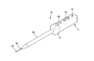
- the medical expansion device 10 opens a puncture hole in a body wall and expands the puncture hole so that another medical device (for example, a catheter or the like) can be inserted into the body cavity from the puncture hole. is there.
- another medical device for example, a catheter or the like
- gastrostomy the case where the medical expansion instrument 10 is used for gastrostomy is described as an example.
- the medical expansion device 10 includes a hollow puncture needle 20 that can be inserted through a guide wire A (see FIG. 16) in the axial direction, and the puncture needle 20 that extends coaxially with the puncture needle 20.
- a cylindrical first dilator 30 that can be inserted through the first dilator 30, a cylindrical second dilator 40 that extends coaxially with the first dilator 30 and can be inserted through the first dilator 30;
- the puncture needle 20 and the case body 11 for supporting the dilators 30 and 40 are provided.
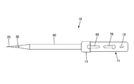
- the case body 11 constitutes a housing that unitizes the entire instrument, and as shown in the figure, the case body 11 has a substantially rectangular parallelepiped shape extending in the front-rear direction and is formed in a size that can be easily grasped with one hand.
- the front side of the case body 11 is a lid portion 12 that closes the front side opening of the lumen that is the internal space of the case body 11. With the lid 12 removed, the components can be housed and assembled in the inner cavity of the case body 11, and the lid 12 is fixed integrally after the housing.
- the case body 11 including the lid portion 12 may be molded from a synthetic resin such as ABS resin, polyacetal, polycarbonate, or the like.
- the lid portion 12 that forms the front side of the case body 11 is provided with a mounting portion 13 that is recessed in a cylindrical shape from the center to the inside, and a base end portion of a second dilator 40 described later is integrated with the mounting portion 13. It is fixed to.
- a guide hole 14 through which a later-described first dilator 30 is slidably penetrated is formed in the bottom of the attachment portion 13.
- a guide hole 15 through which a knock rod 51 of the operation unit 50 described later is slidably penetrated is formed in the rear wall portion of the case body 11.
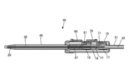
- a storage guide portion 18 for guiding the first slider 16 and the second slider 17 formed in a block shape so as to be movable in the front-rear direction in a state of being lined up in the front-rear direction.
- the storage guide portion 18 extends in the front-rear direction of the inner cavity of the case body 11 and is a portion surrounded by rib-like rail pieces projecting in parallel vertically along the inner walls on both sides. .
- each slider 16, 17 is slightly smaller than the interval between the upper and lower rail pieces, and the width in the horizontal direction of each slider 16, 17 is slightly smaller than the interval between the inner walls on both sides of the case body 11.
- the sliders 16 and 17 are formed in a size that can move smoothly in the front-rear direction (axial direction) along the storage guide portion 18.
- the first slider 16 has a base end portion of the first dilator 30 fixed integrally with the front end thereof, and supports the first dilator 30 in a state of extending from the front side of the case body 11.
- the second slider 17 is configured to support the puncture needle 20 in a state where the proximal end portion of the puncture needle 20 is integrally fixed to the front end thereof and extends from the front side of the case body 11.
- the puncture needle 20 is composed of a thin tube that extends linearly over the entire length of a predetermined length, and is formed of, for example, a metal such as stainless steel.
- a guide wire A (see FIG. 16) can be inserted into the hollow portion of the puncture needle 20.
- the hollow portion communicates in the axial direction from the distal end to the proximal end of the puncture needle 20 and serves as a passage for guiding the guide wire A.
- the tip of the puncture needle 20 has a blade surface for puncturing the skin.
- the first dilator 30 extends coaxially with the puncture needle 20 and has a cylindrical shape through which the puncture needle 20 can be inserted.
- the first dilator 30 is made of a synthetic resin such as polyethylene.
- the hollow portion of the first dilator 30 communicates in the axial direction from the distal end to the proximal end of the first dilator 30 and serves as a passage through which the puncture needle 20 is inserted.
- the inner diameter of the first dilator 30 is substantially equal to the outer diameter of the puncture needle 20 and is set so as not to cause an extra gap.
- the first dilator 30 is set to have a shorter overall length than the puncture needle 20. Therefore, the puncture needle 20 inserted inside the first dilator 30 always projects at least one of the front end portion and the rear end portion thereof to the outside of the first dilator 30. Moreover, the front-end
- the tapered tip may be set so that the tip of the second dilator 40 described below tapers at the same angle as the taper.
- the second dilator 40 extends coaxially with the first dilator 30 and has a cylindrical shape that allows the first dilator 30 to be inserted into the inside.
- the hollow portion of the second dilator 40 communicates in the axial direction from the distal end to the proximal end of the second dilator 40, and serves as a passage through which the first dilator 30 and the puncture needle 20 are inserted.
- the outer diameter of the second dilator 40 is appropriately determined according to a desired size for expanding the puncture hole.
- the inner diameter of the second dilator 40 is not a problem as long as the outer diameter of the first dilator 30 is within the range.
- the second dilator 40 is set to have a shorter overall length than the first dilator 30. Therefore, the first dilator 30 inserted into the inside of the second dilator 40 always protrudes to the outside of the second dilator 40 at least one of the front end portion and the rear end portion thereof.
- the tip of the second dilator 40 is formed in a tapered shape that gradually decreases in diameter toward the tip.
- at least the inner diameter of the tapered minimum diameter end at the distal end portion may be set to be substantially equal to the reference outer diameter excluding the tapered shape of the distal end portion of the first dilator 30.
- the base end portion of the second dilator 40 is integrally fixed to the mounting portion 13 of the lid portion 12 which is the front side of the case body 11 described above.
- the opening of the base end portion of the second dilator 40 communicates with the inner cavity of the case body 11 through the guide hole 14 in the attachment portion 13.
- the base end portion of the first dilator 30 extends from the base end portion of the second dilator 40 to the inner cavity of the case body 11.
- the base end portion of the first dilator 30 is fixed to the first slider 16.
- the first slider 16 is arranged to be movable in the front-rear direction (the axial direction of the first dilator 30) in the inner cavity of the case body 11 as described above. Therefore, the tip of the first dilator 30 appears and disappears from the tip of the second dilator 40 as the first slider 16 moves.
- the first slider 16 is provided with a through-hole 16a for penetrating the inside in the front-rear direction and for fitting and fixing the proximal end portion of the first dilator 30.
- the proximal end portion of the puncture needle 20 is fixed to the second slider 17.
- the second slider 17 is arranged to be movable in the front-rear direction (the axial direction of the puncture needle 20) on the rear side of the first slider 16 in the lumen of the case body 11 as described above.
- the puncture needle 20 extending from the front side of the second slider 17 passes through the through-hole 16a of the first slider 16 located in front of the second slider 17, is inserted into the first dilator 30, and is guided in the axial direction as it is.
- the tip of the puncture needle 20 appears and disappears from the tip of the first dilator 30 as the second slider 17 moves.
- the second slider 17 is provided with an attachment hole 17a that is drilled inside so as to extend in the front-rear direction, and is fitted and fixed to the proximal end portion of the puncture needle 20. Further, a knock rod 51 described later is connected to the rear end side of the second slider 17, and the knock rod 51 has an insertion hole 52 extending inward along its axis. The insertion hole 52 communicates with the attachment hole 17a in the axial direction, and the guide wire A inserted from the insertion hole 52 is guided to the inside of the puncture needle 20 fitted into the attachment hole 17a.
- the case body 11 is moved by a series of operations in the direction in which the distal ends of the puncture needle 20 and the first dilator 30 protrude to the outside.
- the operation unit 50 is provided.
- the operation unit 50 includes a knock rod 51 which is connected to the rear side of the second slider 17 and protrudes from the rear side of the case body 11 so that a series of pushing operations can be performed.
- the knock rod 51 is integrally formed so as to extend in the axial direction from the rear end side of the second slider 17.
- the knock rod 51 penetrates the guide hole 15 on the rear side of the case body 11 and protrudes to the outside, and the user performs a pushing operation.
- An entrance of an insertion hole 52 for inserting the guide wire A is opened at the proximal end of the knock rod 51.
- the inlet may be expanded in a mortar shape so that the tip of the guide wire A can be easily inserted.
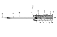
- the case body 11 includes a first lock portion 60 that holds the first slider 16 at a position where the tip end portion of the first dilator 30 protrudes, and the second slider 17 according to the pushing operation of the knock rod 51. And a second lock portion 70 that holds the tip of the puncture needle 20 at a position where the tip portion protrudes.
- the front end portion of the first dilator 30 is held by the first lock portion 60 so as to protrude from the front end portion of the second dilator 40 to the outside. Further, the second lock portion 70 holds the tip of the puncture needle 20 in a state of protruding further outward than the tip of the first dilator 30 protruding outward from the tip of the second dilator 40.
- the first locking portion 60 includes a first locking claw 61 provided on the first slider 16 and a first engaged member provided on the case body 11 and in which the first locking claw 61 is snap-fit engaged. And a stop hole 62.
- the first locking claw 61 extends from the front end to the rear end on the upper surface side of the first slider 16, and protrudes elastically toward the inner wall on the upper surface side of the case body 11. The distal end side of the first locking claw 61 can be elastically deformed up and down.
- the first locked hole 62 is formed in the shape of a narrow groove into which the front end side of the first locking claw 61 is fitted on the upper surface side of the case body 11.
- the first slider 16 is also moved forward by being pushed by the second slider 17 moving forward in the case body 11 together with this.
- the first locked hole 62 is disposed at a position where the first locking claw 61 is exactly matched and engaged. Has been.
- the first slider 16 is urged backward by a coil spring 67 to be described later, and the front end of the first dilator 30 is retracted.
- the front end side of the first engagement hole 62 is provided with a shape that prevents the first engagement hole 62 from being caught on the rear end of the inner edge.
- the front end side of the first locking claw 61 moves forward by the pushing operation of the knock rod 51, it gets over without being caught by the front end of the inner edge of the first locked hole 62, and the upper surface of the case body 11. It is set so that it smoothly contacts the side inner wall.
- the second lock portion 70 is also configured in substantially the same manner as the first lock portion 60, and is provided on the case body 11 with a second locking claw 71 provided on the second slider 17,
- the second locking claw 71 includes a second locked hole 72 for snap-fit engagement.
- the second locking claw 71 extends from the front end to the rear end on the upper surface side of the second slider 17 and protrudes elastically toward the inner wall on the upper surface side of the case body 11.
- the distal end side of the second locking claw 71 can also be elastically deformed up and down.
- the second locked hole 72 is formed in the shape of a narrow groove into which the front end side of the second locking claw 71 is fitted on the upper surface side of the case body 11.
- the second locked hole 72 is disposed at a position where the second locking claw 71 is exactly matched and engaged.
- the second locked hole 72 is located behind the first locked hole 62 on the upper surface side of the case body 11.
- the second slider 17 is also urged backward by a coil spring 77, which will be described later, so that the distal end side of the second locking claw 71 is moved only by the action of the urging force to the rear.
- the second locked hole 72 is provided in such a shape that it cannot be caught on the rear end of the inner edge.
- the front end side of the second locking claw 71 moves forward by the pushing operation of the knock rod 51, it gets over without being caught by the front end of the inner edge of the second locked hole 72, and the upper surface of the case body 11. It is set so that it smoothly contacts the side inner wall.
- the case body 11 has a second lock release portion 75 for releasing the holding by the second lock portion 70 and returning the second slider 17 to a position where the tip of the puncture needle 20 is retracted, and the second lock.
- a second lock release portion 75 for releasing the holding by the second lock portion 70 and returning the second slider 17 to a position where the tip of the puncture needle 20 is retracted, and the second lock.
- the first unlocking portion 65 includes a first push button 66 provided on the case body 11 and a first urging means for urging the first slider 16 to the rear where the tip of the first dilator 30 is immersed. And a coil spring 67.
- the first push button 66 is formed in a clip shape, and the base end side thereof is supported by the upper surface side outer wall of the case body 11 via a fixing portion, and extends rearward in parallel with the upper surface side outer wall.
- the front end side of the first push button 66 is disposed at a position where the protrusion on the back surface faces the inside of the first locked hole 62 from the outside.
- the projection on the back surface on the tip side is fitted into the first locked hole 62, and the snap-fit engagement of the first locking claw 61 is performed. Elastic deformation is possible so as to release
- the coil spring 67 is provided so as to wrap around the base end side of the first dilator 30 on the front side of the first slider 16 in the case body 11.
- the coil spring 67 extends between the inner side of the lid portion 12 of the case body 11 and the front side of the first slider 16 in such a length that the first slider 16 is usually positioned behind the first locked hole 62.
- the first unlocking portion 65 by pressing the first push button 66, the snap fit engagement between the first locking claw 61 and the first locked hole 62 is released, and the first slider 16 is moved by the coil spring 67. The tip of the first dilator 30 is pulled back to the position where it is immersed by the urging force. However, in a state where the second slider 17 is held by the second lock portion 70, the second slider 17 refuses to move the first slider 16 backward. The holding of the lock unit 60 is not released.
- the second unlocking portion 75 is also configured in substantially the same manner as the first unlocking portion 65, and the second push button 76 provided on the case body 11 and the second slider 17 are connected to the puncture needle 20.
- the coil spring 77 is a second urging means that urges the front end portion to immerse backward.
- the second push button 76 is also formed in a clip shape, and the base end side thereof is supported by the upper surface side outer wall of the case body 11 via a fixing portion, and extends forward in parallel with the upper surface side outer wall.
- the front end side of the second push button 76 is arranged at a position where the protrusion on the back surface faces the inside of the second locked hole 72 from the outside.
- the protrusion on the back surface on the tip side is fitted into the second locked hole 72, and the snap-fit engagement of the second locking claw 71 is performed. Elastic deformation is possible so as to release
- the coil spring 77 is provided to wrap around the proximal end side of the puncture needle 20 on the front side of the second slider 17 in the case body 11.
- the coil spring 77 can expand and contract between the front side of the second slider 17 and the rear side of the first slider 16, and contracts when the second slider 17 moves forward in accordance with the pushing operation of the knock rod 51.
- the first slider 16 is urged forward and moved, and contracted while the first slider 16 is held, the second slider 17 is urged rearward where the tip of the puncture needle 20 is retracted. Is set to
- the second lock release portion 75 by pressing the second push button 76, the snap fit engagement between the second locking claw 71 and the second locked hole 72 is released, and the second slider 17 is moved by the coil spring 77. The tip of the puncture needle 20 is pulled back to the position where it is immersed by the urging force. At this time, the second locking claw 71 is set to engage with the initial locked hole 19 in the case body 11. Further, as described above, the first lock release unit 65 can release the holding by the first lock unit 60 on the condition that the second lock release unit 75 releases the holding by the second lock unit 70. ing.
- the puncture needle 20 and the tip of the first dilator 30 may be stored inside the second dilator 40 as shown in FIGS. In this way, in the initial state where the tip of the puncture needle 20 and the first dilator 30 does not protrude to the outside, the tip of the puncture needle 20 and the first dilator 30 is damaged, or the tip itself Can be easily handled, and the medical extension device 10 can be easily handled.
- the distal end portion of the first dilator 30 having a small diameter on the inner side is moved outside from the distal end portion of the outermost second dilator 40 by a series of operations of the operation portion 50. Further, the distal end portion of the puncture needle 20 inside the first dilator 30 is also projected outward from the distal end portion of the first dilator 30.
- the tip of the puncture needle 20 and the first dilator 30 is inserted into the inside of the second dilator 40, respectively.
- a knock rod 51 protrudes from the rear side of the case body 11.
- the second slider 17 integrated with the knock rod 51 moves forward in the case body 11, and the puncture needle 20 supported by the second slider 17 also moves forward together.
- the second locking claw 71 on the second slider 17 moves away from the initial locked hole 19 in the case body 11 and moves forward while elastically sliding on the inner wall on the upper surface side of the case body 11. To do.
- the first slider 16 is also pushed forward and moved through the second slider 17 and the coil spring 77 on the front side thereof, and is supported by the first slider 16.
- the dilator 30 also moves forward together.
- the first locking claw 61 in the first slider 16 is disengaged from the second locked hole 72 in the case body 11 and moves forward while elastically sliding on the inner wall on the upper surface side of the case body 11. Moving.
- the knock rod 51 is pushed forward against the urging force of the two coil springs 67 and 77.
- the first locking claw 61 on the first slider 16 enters the first locked hole 62 on the case body 11. Mate and snap fit into engagement.
- the first lock portion 60 can hold the tip end portion of the first dilator 30 at the position protruding outside from the tip end portion of the second dilator 40.
- the second locking claw 71 on the second slider 17 is aligned with the second locked hole 72 on the case body 11. Then snap-fit engagement.
- the second lock portion 70 can hold the tip of the puncture needle 20 in a position that protrudes outward from the tip of the first dilator 30 as it is.
- the puncture hole is expanded with the first dilator 30 with a small diameter, and then the second dilator 40 with a larger diameter. It is possible to expand the puncture hole in two steps in a larger and smoother manner.
- the distal end portion of the first dilator 30 having a small diameter can also be smoothly inserted into the puncture hole in combination with the small diameter by forming a tapered shape.
- the puncture needle 20 that is at the forefront is protruded and pushed forward so as to expand the puncture hole by the first dilator 30, the body cavity may be damaged at the tip of the puncture needle 20. Therefore, when the distal end portion of the first dilator 30 reaches the puncture hole, the puncture needle 20 may be retracted from the distal end portion of the first dilator 30 into a state (initial state).
- the second lock release unit 75 releases the holding by the second lock unit 70 and automatically moves the second slider 17 to the position where the tip of the puncture needle 20 is retracted. Can be restored. Thereafter, by pushing the first dilator 30 into the puncture hole, the puncture hole can be safely expanded without damaging the body cavity with the puncture needle 20.
- the distal end of the first dilator 30 having a small diameter is projected and the second dilator 40 is pushed to expand the puncture hole, the distal end of the first dilator 30 may cause a mistake in the body cavity. There is also a risk of hurting. Therefore, when the tip end portion of the second dilator 40 reaches the puncture hole, the first dilator 30 may be retracted into the state where the tip portion of the second dilator 40 is immersed inside.
- the first lock release unit 65 releases the holding by the first lock unit 60, and the first slider 16 is moved.
- the tip of the second dilator 40 can be automatically returned to the position where it is immersed. Thereafter, by pushing only the second dilator 40 into the puncture hole, the puncture hole can be safely expanded without damaging the body cavity.
- the distal end side of the first push button 66 is pressed toward the case body 11 side. . Then, the first push button 66 is elastically deformed, and the protrusion on the back surface on the tip side is fitted into the first locked hole 62, and the snap fit engagement of the first locking claw 61 is released.
- the first slider 16 is pulled back to the initial position where the tip of the first dilator 30 is immersed by the biasing force of the coil spring 67.
- the first locking claw 61 engages with the second locked hole 72 and stops.
- the second slider 17 refuses to move the first slider 16 backward.
- the holding of the one lock unit 60 is not released. Therefore, even if the first push button 66 is pushed by mistake in the operation procedure, it can be operated safely without being activated.
- the operation for projecting the puncture needle 20 or the first dilator 30 can be performed only by a series of pushing operations with respect to one knock rod 51. Further, the operation for immersing the puncture needle 20 through the first dilator 30 can be performed in two stages by operating the separate push buttons 66 and 76. These operations can also be easily performed with only one hand holding the case body 11.
- FIG. 10 to FIG. 14 show the flow of a procedure in which a puncture hole is formed in the abdominal wall 1 and the stomach wall 2 without using the guide wire A with the medical expansion instrument 10 alone, and the puncture hole is expanded as a fistula.
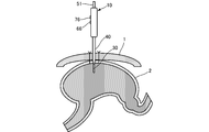
- step 1 shown in FIG. 10 the abdominal wall 1 and the stomach wall 2 are fixed in advance with sutures, and the medical dilator 10 is brought into a state where both the puncture needle 20 and the first dilator 30 protrude, and the abdominal wall 1 is punctured.
- the tip of the needle 20 is abutted and pushed forward, and puncture is performed until the tip of the puncture needle 20 or the first dilator 30 enters the stomach.
- the actual stomach is narrow, and if the puncture needle 20 is pushed further from the state shown in FIG.
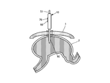
- step 2 shown in FIG. 11 the second push button 76 is pressed to house the puncture needle 20 inside the first dilator 30.
- the first dilator 30 is pushed out in a protruding state, and the puncture hole is opened by the first dilator 30 until the tip of the second dilator 40 enters the stomach as shown in step 3 in FIG. Expand.
- the first dilator 30 is pushed forward as it is, there is a risk that the distal wall of the first dilator 30 may puncture the posterior stomach wall.
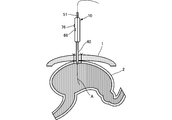
- step 4 shown in FIG. 13 when the distal end portion of the second dilator 40 is confirmed by the endoscope in the stomach, the first push button 66 is pressed, and the first dilator 30 is also inside the second dilator 40. Store in.
- the puncture hole is pushed further by the second dilator 40 in step 5 shown in FIG. It is expanded to the outer diameter.
- the puncture needle 20 does not have to puncture the entire length protruding from the distal end portion of the first dilator 30 into the stomach.
- the procedure using the guide wire A can be operated more safely.
- the guide wire A is inserted into the hollow portion of the puncture needle 20.
- the puncture needle 20 is immersed in the first dilator 30. Thereafter, by pushing the first dilator 30 along the guide wire A, the puncture hole can be expanded more safely.
- the balloon catheter which is another medical device, is inserted into the expanded puncture hole.
- the balloon is inflated with distilled water or the like.
- a fixing tool is applied to the portion exposed from the surface of the abdominal wall 1, and the balloon catheter is fixed to the stomach wall.
- FIGS. 15 to 20 show the flow of a procedure in which a puncture hole is opened in the abdominal wall 1 and the stomach wall 2 by the medical expansion instrument 10 using the guide wire A, and the puncture hole is expanded as a fistula.
- step 1 shown in FIG. 15 the abdominal wall 1 and the stomach wall 2 are fixed in advance with sutures, and the medical dilator 10 is brought into a state in which both the puncture needle 20 and the first dilator 30 protrude, and the abdominal wall 1 is punctured.
- the tip of the needle 20 is abutted and pushed forward, and puncture is performed until the tip of the puncture needle 20 enters the stomach.
- step 2 shown in FIG. 16 when the tip of the puncture needle 20 is confirmed by an endoscope in the stomach, the guide wire A is inserted from the entrance of the insertion hole 52 opened in the knock rod 51.
- the guide wire A inserted through the insertion hole 52 is directly guided to the inside of the puncture needle 20 through which the insertion hole 52 communicates.
- the actual stomach is narrow, and if the case body 11 is further pushed forward from the state shown in FIG. 16, there is a possibility that the distal end of the puncture needle 20 punctures the back stomach wall.
- step 3 shown in FIG. 17 after the guide wire A is sufficiently inserted into the stomach, the second push button 76 is pressed to store the puncture needle 20 inside the first dilator 30.
- the first dilator 30 is pushed along the guide wire A in a state where only the first dilator 30 protrudes.
- step 4 shown in FIG. 18 the puncture hole is expanded by the first dilator 30 until the distal end portion of the second dilator 40 enters the stomach.
- the first dilator 30 is pushed forward as it is, there is a risk that the distal wall of the first dilator 30 may puncture the posterior stomach wall.
- step 5 shown in FIG. 19 when the distal end portion of the second dilator 40 is confirmed by the endoscope in the stomach, the first push button 66 is pressed, and the first dilator 30 is also inside the second dilator 40.
- the second dilator 40 is further pushed forward as shown in step 6 of FIG. Expanded to 40 outer diameters. Note that the indwelling of the balloon catheter after expansion of the puncture hole is the same as the processing when the guide wire A is not used.
- the guide wire A can be inserted into the puncture needle 20, and the guide wire A can be inserted from the insertion hole 52 of the knock rod 51. Therefore, a procedure using the guide wire A is possible as necessary, and an optimal usage form can be selected as appropriate.
- the tip of the puncture needle 20 and the first dilator 30 can be protruded by only a series of operations of pushing the knock rod 51 of the operation unit 50.
- the first lock portion 60 and the second lock portion 70 can hold the puncture needle 20 and the distal end portion of the first dilator 30 as they are projected.
- the distal end portion of the puncture needle 20 can be sunk by simply pressing the second push button 76 of the second unlocking portion 75, and then the first push button 66 of the first unlocking portion 65 can be simply pushed.
- the tip of the first dilator 30 can also be immersed.
- the knock rod 51 and the push buttons 66 and 76 that need to be operated by the user can be easily operated with only one hand holding the case body 11, and the usability can be improved.
- the operation unit 50, the first lock unit 60, the second lock unit 70, and the first lock release unit 65 and the second lock release unit 75 can each be realized with a relatively simple configuration.
- the first slider 16 has a through hole 16a through which the puncture needle 20 fixed to the second slider 17 is inserted and guided to the inside of the first dilator 30 fixed to the first slider 16. Therefore, the components can be arranged so as to be aligned on the same axis, and the case body 11 can be configured to be compact overall. Further, since the case body 11 forms a housing that unitizes the entire apparatus, the convenience of handling and carrying can be further enhanced.
- a sheath 80 which is another medical device, may be extrapolated to the second dilator 40.
- the sheath 80 is a cylindrical member having a lumen through which the dilator (second dilator 40) can be inserted, and is attached to the outer periphery of the second dilator 40.
- a pair of blade pieces 81, 81 extending on both sides substantially orthogonal to the axial direction are provided at the proximal end portion of the sheath 80.
- the sheath 80 has a shorter overall length than the second dilator 40 and is set so that the opening of the tip is located at the start of the taper at the tip of the second dilator 40.
- the edge of the distal end opening of the sheath 80 is formed in a taper shape that tapers at the same angle as the tip end portion of the second dilator 40 tapers, and each Taber surface is smoothly continuous. .
- Such a sheath 80 is inserted into the puncture hole together with the second dilator 40 and then left in the puncture hole after the second dilator 40 is removed, so that the balloon catheter is inserted into the puncture hole via the sheath 80. Can be easily inserted into.
- the sheath 80 is held in a state where the pair of blade pieces 81 and 81 are in contact with the body wall surface.
- the sheath 80 is to be removed by breaking after the balloon catheter is placed in the puncture hole.
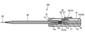
- the medical expansion device 10A according to the present embodiment is not the first dilator 30 having a small diameter, and is the first in that only the puncture needle 20 can be inserted inside the second dilator 40. This is different from the embodiment.
- symbol is attached
- the lock release unit 65 is also not provided.
- the lock portion 70 that holds the slider 17 that is the same as the second slider 17 at a position where the distal end portion of the puncture needle 20 protrudes outward from the distal end portion of the second dilator 40 is the same as the second lock portion 70. It is.
- the lock release unit 75 that releases the holding by the lock unit 70 and returns the slider 17 to the position where the tip of the puncture needle 20 is retracted is the same as the second lock release unit 75.
- the configuration of the lid 12 that closes the front opening of the case body 11 is slightly different. That is, on the opposite side (inner side) of the attachment portion 13 of the lid portion 12, a convex portion 12a that fits in front of the storage guide portion 18 is integrally provided, and puncture is performed so as to pass through the axial center of the convex portion 12a. An insertion hole 12b for guiding the needle 20 is formed.
- the puncture needle 20 is inserted by the unlocking portion 75, and then the second die.
- the puncture hole is expanded by the lator 40.
- the puncture hole cannot be expanded in two steps as in the first embodiment described above, but the configuration is simplified correspondingly, and the configuration can be made more compact and inexpensive.
- the urging means is constituted by a coil spring, but may be constituted by another elastically deformable member. Furthermore, if the taper-shaped spread angle of the tip portion of the first dilator 30 is set to the same angle as the taper-shaped spread angle of the tip portion of the second dilator 40, the second dilator 30 will be Since it spreads at a uniform angle to the outer diameter of the dilator 40, the puncture hole can be smoothly expanded to the size of the outer diameter of the second dilator 40.
- the medical expansion device according to the present invention is not limited to a dilator for inserting a medical device from a puncture hole opened in a body wall into a body cavity.
- the medical expansion device expands a urethra, an esophageal stenosis, a colon stenosis, or the like. It can also be used as a bougie.
Landscapes
- Health & Medical Sciences (AREA)
- Surgery (AREA)
- Life Sciences & Earth Sciences (AREA)
- Medical Informatics (AREA)
- Nuclear Medicine, Radiotherapy & Molecular Imaging (AREA)
- Engineering & Computer Science (AREA)
- Biomedical Technology (AREA)
- Heart & Thoracic Surgery (AREA)
- Pathology (AREA)
- Molecular Biology (AREA)
- Animal Behavior & Ethology (AREA)
- General Health & Medical Sciences (AREA)
- Public Health (AREA)
- Veterinary Medicine (AREA)
- Surgical Instruments (AREA)
- Media Introduction/Drainage Providing Device (AREA)
Applications Claiming Priority (2)
| Application Number | Priority Date | Filing Date | Title |
|---|---|---|---|
| JP2015214928A JP6412483B2 (ja) | 2015-10-30 | 2015-10-30 | 医療用拡張器具 |
| JP2015-214928 | 2015-10-30 |
Publications (1)
| Publication Number | Publication Date |
|---|---|
| WO2017073454A1 true WO2017073454A1 (ja) | 2017-05-04 |
Family
ID=58630167
Family Applications (1)
| Application Number | Title | Priority Date | Filing Date |
|---|---|---|---|
| PCT/JP2016/081120 Ceased WO2017073454A1 (ja) | 2015-10-30 | 2016-10-20 | 医療用拡張器具 |
Country Status (2)
| Country | Link |
|---|---|
| JP (1) | JP6412483B2 (https=) |
| WO (1) | WO2017073454A1 (https=) |
Cited By (5)
| Publication number | Priority date | Publication date | Assignee | Title |
|---|---|---|---|---|
| CN109984818A (zh) * | 2017-12-31 | 2019-07-09 | 江苏风和医疗器材股份有限公司 | 一种无芯穿刺器 |
| CN113397809A (zh) * | 2021-06-11 | 2021-09-17 | 北京奥京生物科技有限公司 | 青光眼微创手术推注器 |
| CN113797014A (zh) * | 2020-06-12 | 2021-12-17 | 上海交通大学医学院附属瑞金医院 | 一体化微型体腔温热治疗仪 |
| CN115461002A (zh) * | 2020-03-11 | 2022-12-09 | 苏州市立普医疗科技有限公司 | 穿刺支架及活检装置 |
| CN116492099A (zh) * | 2023-06-16 | 2023-07-28 | 昆明市第一人民医院 | 一种大鼠树鼩异种原位肝移植模型建立方法 |
Families Citing this family (1)
| Publication number | Priority date | Publication date | Assignee | Title |
|---|---|---|---|---|
| JP7618475B2 (ja) * | 2021-03-26 | 2025-01-21 | テルモ株式会社 | 医療用穿刺デバイス及びカテーテル組立体 |
Citations (5)
| Publication number | Priority date | Publication date | Assignee | Title |
|---|---|---|---|---|
| JPS56166007U (https=) * | 1980-05-15 | 1981-12-09 | ||
| US5242427A (en) * | 1990-11-06 | 1993-09-07 | Ethicon, Inc. | Surgical instrument forming a trocar |
| US20100036409A1 (en) * | 2002-02-28 | 2010-02-11 | Scheib Mark S | Retractable dilator needle |
| WO2013065292A1 (ja) * | 2011-10-31 | 2013-05-10 | 住友ベークライト株式会社 | 医療用拡張器および医療用拡張器セット |
| JP5632224B2 (ja) * | 2010-07-29 | 2014-11-26 | 住友ベークライト株式会社 | 胃瘻造設術用拡張器 |
Family Cites Families (2)
| Publication number | Priority date | Publication date | Assignee | Title |
|---|---|---|---|---|
| AU648135B2 (en) * | 1991-01-15 | 1994-04-14 | Ethicon Inc. | Knife for surgical trocar |
| JP3683954B2 (ja) * | 1995-11-14 | 2005-08-17 | オリンパス株式会社 | 気腹針 |
-
2015
- 2015-10-30 JP JP2015214928A patent/JP6412483B2/ja active Active
-
2016
- 2016-10-20 WO PCT/JP2016/081120 patent/WO2017073454A1/ja not_active Ceased
Patent Citations (5)
| Publication number | Priority date | Publication date | Assignee | Title |
|---|---|---|---|---|
| JPS56166007U (https=) * | 1980-05-15 | 1981-12-09 | ||
| US5242427A (en) * | 1990-11-06 | 1993-09-07 | Ethicon, Inc. | Surgical instrument forming a trocar |
| US20100036409A1 (en) * | 2002-02-28 | 2010-02-11 | Scheib Mark S | Retractable dilator needle |
| JP5632224B2 (ja) * | 2010-07-29 | 2014-11-26 | 住友ベークライト株式会社 | 胃瘻造設術用拡張器 |
| WO2013065292A1 (ja) * | 2011-10-31 | 2013-05-10 | 住友ベークライト株式会社 | 医療用拡張器および医療用拡張器セット |
Cited By (7)
| Publication number | Priority date | Publication date | Assignee | Title |
|---|---|---|---|---|
| CN109984818A (zh) * | 2017-12-31 | 2019-07-09 | 江苏风和医疗器材股份有限公司 | 一种无芯穿刺器 |
| CN109984818B (zh) * | 2017-12-31 | 2021-12-31 | 江苏风和医疗器材股份有限公司 | 一种无芯穿刺器 |
| CN115461002A (zh) * | 2020-03-11 | 2022-12-09 | 苏州市立普医疗科技有限公司 | 穿刺支架及活检装置 |
| CN113797014A (zh) * | 2020-06-12 | 2021-12-17 | 上海交通大学医学院附属瑞金医院 | 一体化微型体腔温热治疗仪 |
| CN113397809A (zh) * | 2021-06-11 | 2021-09-17 | 北京奥京生物科技有限公司 | 青光眼微创手术推注器 |
| CN116492099A (zh) * | 2023-06-16 | 2023-07-28 | 昆明市第一人民医院 | 一种大鼠树鼩异种原位肝移植模型建立方法 |
| CN116492099B (zh) * | 2023-06-16 | 2023-09-15 | 昆明市第一人民医院 | 一种用于大鼠树鼩异种原位肝移植的胆管穿刺器 |
Also Published As
| Publication number | Publication date |
|---|---|
| JP6412483B2 (ja) | 2018-10-24 |
| JP2017080316A (ja) | 2017-05-18 |
Similar Documents
| Publication | Publication Date | Title |
|---|---|---|
| JP6412483B2 (ja) | 医療用拡張器具 | |
| US11577054B2 (en) | Intravenous catheter insertion device and method of use | |
| JP5164769B2 (ja) | 縫合器 | |
| JP5086648B2 (ja) | 処置具 | |
| JP4435094B2 (ja) | 拡張可能なニードル縫合装置及び関連するハンドル・アセンブリー | |
| JP4481880B2 (ja) | ステント留置装置 | |
| JP5371610B2 (ja) | 縫合器 | |
| JP2005534436A (ja) | 安全なカテーテル | |
| US20110137252A1 (en) | Device for providing a percutaneous endoscopic gastrostomy | |
| US20200289788A1 (en) | Apparatus and methods for Loading Suture | |
| JPH08257131A (ja) | 針後退装置を備えたカテーテルと針導入器とのアセンブリ | |
| KR20140087032A (ko) | 의료용 확장기 및 의료용 확장기 세트 | |
| CN114246674A (zh) | 用于血管介入手术机器人的递送辅助装置及从端部分 | |
| JP2017164423A (ja) | カテーテル組立体 | |
| JP2009254812A (ja) | 縫合器 | |
| JP6562330B2 (ja) | 内視鏡用処置具 | |
| JP2011182986A (ja) | 臓器固定具用挿入補助具 | |
| CN109310857A (zh) | 插管装置 | |
| US5713868A (en) | Catheterization device with dilator | |
| JP2008295609A (ja) | 内視鏡用前方突出型処置具 | |
| JP2006304994A (ja) | ステント留置装置 | |
| JP5859612B2 (ja) | 臓器固定具用挿入補助具 | |
| JP2010012052A (ja) | 胃瘻用カテーテル及び胃瘻用カテーテルキット | |
| JP2010000276A (ja) | 留置針 | |
| JPS60227771A (ja) | 留置チユ−ブガイド装置 |
Legal Events
| Date | Code | Title | Description |
|---|---|---|---|
| 121 | Ep: the epo has been informed by wipo that ep was designated in this application |
Ref document number: 16859684 Country of ref document: EP Kind code of ref document: A1 |
|
| NENP | Non-entry into the national phase |
Ref country code: DE |
|
| 122 | Ep: pct application non-entry in european phase |
Ref document number: 16859684 Country of ref document: EP Kind code of ref document: A1 |