WO2017073178A1 - 電力変換装置 - Google Patents
電力変換装置 Download PDFInfo
- Publication number
- WO2017073178A1 WO2017073178A1 PCT/JP2016/076519 JP2016076519W WO2017073178A1 WO 2017073178 A1 WO2017073178 A1 WO 2017073178A1 JP 2016076519 W JP2016076519 W JP 2016076519W WO 2017073178 A1 WO2017073178 A1 WO 2017073178A1
- Authority
- WO
- WIPO (PCT)
- Prior art keywords
- power
- phase
- power supply
- line
- conversion module
- Prior art date
Links
Images

Classifications
-
- H—ELECTRICITY
- H02—GENERATION; CONVERSION OR DISTRIBUTION OF ELECTRIC POWER
- H02M—APPARATUS FOR CONVERSION BETWEEN AC AND AC, BETWEEN AC AND DC, OR BETWEEN DC AND DC, AND FOR USE WITH MAINS OR SIMILAR POWER SUPPLY SYSTEMS; CONVERSION OF DC OR AC INPUT POWER INTO SURGE OUTPUT POWER; CONTROL OR REGULATION THEREOF
- H02M7/00—Conversion of ac power input into dc power output; Conversion of dc power input into ac power output
- H02M7/02—Conversion of ac power input into dc power output without possibility of reversal
- H02M7/04—Conversion of ac power input into dc power output without possibility of reversal by static converters
- H02M7/12—Conversion of ac power input into dc power output without possibility of reversal by static converters using discharge tubes with control electrode or semiconductor devices with control electrode
- H02M7/21—Conversion of ac power input into dc power output without possibility of reversal by static converters using discharge tubes with control electrode or semiconductor devices with control electrode using devices of a triode or transistor type requiring continuous application of a control signal
- H02M7/217—Conversion of ac power input into dc power output without possibility of reversal by static converters using discharge tubes with control electrode or semiconductor devices with control electrode using devices of a triode or transistor type requiring continuous application of a control signal using semiconductor devices only
-
- H—ELECTRICITY
- H02—GENERATION; CONVERSION OR DISTRIBUTION OF ELECTRIC POWER
- H02M—APPARATUS FOR CONVERSION BETWEEN AC AND AC, BETWEEN AC AND DC, OR BETWEEN DC AND DC, AND FOR USE WITH MAINS OR SIMILAR POWER SUPPLY SYSTEMS; CONVERSION OF DC OR AC INPUT POWER INTO SURGE OUTPUT POWER; CONTROL OR REGULATION THEREOF
- H02M7/00—Conversion of ac power input into dc power output; Conversion of dc power input into ac power output
- H02M7/02—Conversion of ac power input into dc power output without possibility of reversal
- H02M7/04—Conversion of ac power input into dc power output without possibility of reversal by static converters
- H02M7/06—Conversion of ac power input into dc power output without possibility of reversal by static converters using discharge tubes without control electrode or semiconductor devices without control electrode
- H02M7/066—Conversion of ac power input into dc power output without possibility of reversal by static converters using discharge tubes without control electrode or semiconductor devices without control electrode particular circuits having a special characteristic
-
- H—ELECTRICITY
- H02—GENERATION; CONVERSION OR DISTRIBUTION OF ELECTRIC POWER
- H02M—APPARATUS FOR CONVERSION BETWEEN AC AND AC, BETWEEN AC AND DC, OR BETWEEN DC AND DC, AND FOR USE WITH MAINS OR SIMILAR POWER SUPPLY SYSTEMS; CONVERSION OF DC OR AC INPUT POWER INTO SURGE OUTPUT POWER; CONTROL OR REGULATION THEREOF
- H02M1/00—Details of apparatus for conversion
- H02M1/0003—Details of control, feedback or regulation circuits
- H02M1/0006—Arrangements for supplying an adequate voltage to the control circuit of converters
-
- H—ELECTRICITY
- H02—GENERATION; CONVERSION OR DISTRIBUTION OF ELECTRIC POWER
- H02M—APPARATUS FOR CONVERSION BETWEEN AC AND AC, BETWEEN AC AND DC, OR BETWEEN DC AND DC, AND FOR USE WITH MAINS OR SIMILAR POWER SUPPLY SYSTEMS; CONVERSION OF DC OR AC INPUT POWER INTO SURGE OUTPUT POWER; CONTROL OR REGULATION THEREOF
- H02M7/00—Conversion of ac power input into dc power output; Conversion of dc power input into ac power output
- H02M7/02—Conversion of ac power input into dc power output without possibility of reversal
- H02M7/04—Conversion of ac power input into dc power output without possibility of reversal by static converters
- H02M7/05—Capacitor coupled rectifiers
Definitions
- the present invention when power is supplied from the three-phase AC power source to the power supply unit of the power converter, a step-down circuit can be eliminated, a low withstand voltage element can be used, and noise elimination components can be reduced.
- the present invention relates to a power conversion device.
- a power converter such as a converter or an inverter is used.
- a power source for driving a switching element or the like is required.
- Patent Document 1 power is supplied through a power supply wiring connected to a neutral line of a three-phase four-wire AC power supply and any one of three-phase power lines of R phase, S phase, and T phase.
- An air conditioner having a power conversion device with a receiving power supply is described.
- Patent Document 2 describes an electric motor control device having a power supply unit that receives power supply from any two phases of R-phase, S-phase, and T-phase power lines as a power conversion device.
- the three-phase four-wire AC power source having a neutral wire is connected to the power converter of the air conditioner, so that noise generated in the power converter includes a neutral wire. Since all four lines leak out to the outside (power supply system), a noise removing component such as a noise filter for the four lines is required between the power conversion device and the power supply system.
- the device described in Patent Document 2 uses a neutral wire and does not use a neutral wire, but obtains power from any two of the three phases.
- the power supply unit of the motor control device must convert the three-phase line voltage to a desired power supply voltage, but generally the three-phase line voltage is 200V or 400V, which is a high voltage. Therefore, it is necessary to consider the insulation measures for the power supply unit, the withstand voltage of the elements of the power supply unit, and the addition of a step-down circuit.
- the present invention has been made in view of the above, and when power is supplied from a three-phase AC power source to a power supply unit of a power converter, a step-down circuit may be unnecessary or a low withstand voltage element may be used.
- An object of the present invention is to provide a power conversion device that can reduce noise reduction components.
- a power conversion device includes a power conversion module that converts input three-phase AC power into desired power and outputs the power, and the power conversion module.
- a power conversion device having a drive control unit that drives an active element to be generated and a power supply unit that generates a power supply voltage used by the drive control unit and outputs the power supply voltage to the drive control unit, the power conversion device being provided before the power conversion module
- a three-phase AC power line that outputs the three-phase AC power connected to the input side of the power conversion module to the power conversion module, one of the three-phase AC power lines, and the other one-phase power line
- the power conversion device includes a power conversion module that converts input three-phase AC power into desired power and outputs the power, a drive control unit that drives an active element included in the power conversion module, and the drive A power conversion device having a power supply unit that generates a power supply voltage used in the control unit and outputs the power supply voltage to the drive control unit, provided in a front stage of the power conversion module and connected to an input side of the power conversion module Any one of the three-phase AC power lines for outputting the three-phase AC power to the power conversion module, three filter capacitors star-connected between the three-phase AC power lines, and the three-phase AC power lines. A power supply line connected between the power line and the power supply unit and between the filter capacitor and the power supply unit to supply power to the power supply unit. And said that there were pictures.
- the line voltage of the power line is about half of the three-phase line voltage, eliminating the need for a step-down circuit.
- no neutral wires are used for the three-phase four-wire AC power supply, it is no longer necessary to use noise removing components for all four wires. Can be reduced.
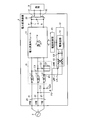
- FIG. 1 is a diagram showing a configuration of a power conversion device according to an embodiment of the present invention.
- FIG. 2 is a diagram showing a configuration of a modification of the power conversion device according to the embodiment of the present invention.
- FIG. 1 is a diagram showing a configuration of a power conversion device 1 according to an embodiment of the present invention.
- the power conversion device 1 includes a power conversion module 11 and a three-phase AC power line 20 including an R-phase power line 21, an S-phase power line 22, and a T-phase power line 23.
- the power converter 1 is supplied with three-phase AC power from an external three-phase AC power source 2.
- the supplied R-phase, S-phase, and T-phase power is supplied to the power conversion module 11 via the three-phase AC power line 20.
- the L-type filter 10 is provided in the three-phase AC power line 20.
- reactors L 1, L 2, and L 3 are respectively provided on the R-phase power line 21, the S-phase power line 22, and the T-phase power line 23, and between the R-phase power line 21, the S-phase power line 22, and the T-phase power line 23.
- filter capacitors C1, C2, and C3 are star-connected to each other.
- the L-type filter 10 is a low-pass filter and removes normal mode noise.
- the power conversion module 11 drives and controls the input three-phase AC power to the active element 11a such as a switching element, and converts it into desired power and outputs it.
- the active element 11a such as a switching element
- three-phase AC power is converted into DC power generated between PN.
- the power conversion module 11 functions as a converter.
- the power conversion module 11 may function as an AC-AC converter that converts three-phase AC power into AC power such as two-phase or three-phase.
- the power conversion module 11 may include a converter and an inverter.
- the power conversion module 11 may be a matrix converter.
- the DC power between PN output from the power conversion module 11 is supplied to a load 3 such as a DC motor provided outside via an output power line 30 including a P power line 31 and an N power line 32.
- the P power line 31 is provided with a reactor L.
- a capacitor C is provided between the P power line 31 and the N power line 32. Reactor L and capacitor C function as a low-pass filter.
- the drive control unit 15 drives and controls the active element 11a included in the power conversion module 11.
- the power supply unit 12 generates various control voltages necessary for drive control of the drive control unit 15 and supplies them to the drive control unit 15.
- the power supply line LN1 is wired between the point P1 on the T-phase power line 23 and the power supply unit 12.
- the point P1 may be on the R-phase power line 21 or on the S-phase power line 22.
- the power supply line LN2 is wired between the middle point P2 between the star-connected filter capacitors C1, C2, and C3 and the power supply unit 12.
- the power supply lines LN1 and LN2 are power supply lines LN that supply branch power obtained by branching a part of power from the three-phase AC power line 20 to the power supply unit 12.
- the power supply circuit 14 converts the input DC voltage into various control voltages necessary for drive control of the drive control unit 15 and supplies the converted control voltages to the drive control unit 15.
- the power supply circuit 14 is realized by, for example, a switching regulator.
- the voltage between the middle point P2 and each phase is 1 / ⁇ (3) of the line voltage of the three-phase AC power line 20. Therefore, the line voltage of the power supply line LN is 1 / ⁇ (3) of the line voltage of the three-phase AC power line 20.
- the line voltage of the power supply line LN is about 230V. Therefore, the breakdown voltage of the element in the power supply unit 12 can be reduced. Further, it is not necessary to take excessive insulation measures or provide a step-down circuit in the power supply unit 12. As a result, the power supply unit 12 can reduce the device scale and can be made inexpensive.
- the middle point P2 is between the star-connected filter capacitors constituting the existing L-type filter 10, the line of the three-phase AC power line 20 is the same as the neutral line of the three-phase four-wire AC power supply. A voltage about 1 / ⁇ (3) of the inter-voltage can be obtained. And since the neutral wire is not used, the structure for the noise countermeasure between the three-phase alternating current power supply 2 and the power converter device 1 becomes unnecessary for a neutral wire. For this reason, the noise removal component about a neutral line becomes unnecessary. Further, since the midpoint P2 is obtained by using the existing L-type filter 10, it is not necessary to add a special configuration and it is not necessary to increase the number of parts.
- the voltage (effective value) of the capacitor C3 was 226.4 V when C1 to C3 were 10 ⁇ F and the power used by the power supply unit 12 (power acquired from the T phase) was 31.1 W. Since the voltage (running value) when the acquired power from the T phase is zero is 230V, the voltage drop of the capacitor C3 is about 4V, and it has been found that the function of C3 as a filter is not impaired. .
- the midpoint P2 described above is a midpoint between the star-connected filter capacitors constituting the existing L-type filter 10.
- the present invention is not limited to this, and as shown in FIG. C23 may be provided to form the midpoint P3.
- the point P1 is provided on the T-phase power line 23, and two capacitors C22 and C23 connected in series are newly connected between the S-phase power line 22 and the T-phase power line 23.
- the midpoint P3 is the midpoint of the capacitors C22 and C23.
- the voltage at the midpoint P3 is 1 ⁇ 2 of the line voltage between the S-phase power line 22 and the T-phase power line 23.
- Capacitors C22 and C23 only need to be able to divide the line voltage of three-phase AC power line 20 into two, and when point P1 is provided on T-phase power line 23, between T-phase power line 23 and S-phase power line 22, or The T-phase power line 23 and the R-phase power line 21 are provided.
Landscapes
- Engineering & Computer Science (AREA)
- Power Engineering (AREA)
- Inverter Devices (AREA)
- Rectifiers (AREA)
- Power Conversion In General (AREA)
Priority Applications (3)
| Application Number | Priority Date | Filing Date | Title |
|---|---|---|---|
| CN201680062852.0A CN108377664B (zh) | 2015-10-30 | 2016-09-08 | 电力转换装置 |
| EP16859415.8A EP3370333B1 (de) | 2015-10-30 | 2016-09-08 | Stromwandlungsvorrichtung |
| AU2016345858A AU2016345858B2 (en) | 2015-10-30 | 2016-09-08 | Power converter |
Applications Claiming Priority (2)
| Application Number | Priority Date | Filing Date | Title |
|---|---|---|---|
| JP2015214497A JP6210102B2 (ja) | 2015-10-30 | 2015-10-30 | 電力変換装置 |
| JP2015-214497 | 2015-10-30 |
Publications (1)
| Publication Number | Publication Date |
|---|---|
| WO2017073178A1 true WO2017073178A1 (ja) | 2017-05-04 |
Family
ID=58630157
Family Applications (1)
| Application Number | Title | Priority Date | Filing Date |
|---|---|---|---|
| PCT/JP2016/076519 WO2017073178A1 (ja) | 2015-10-30 | 2016-09-08 | 電力変換装置 |
Country Status (5)
| Country | Link |
|---|---|
| EP (1) | EP3370333B1 (de) |
| JP (1) | JP6210102B2 (de) |
| CN (1) | CN108377664B (de) |
| AU (1) | AU2016345858B2 (de) |
| WO (1) | WO2017073178A1 (de) |
Citations (4)
| Publication number | Priority date | Publication date | Assignee | Title |
|---|---|---|---|---|
| JPH07198154A (ja) * | 1994-01-12 | 1995-08-01 | Sanyo Electric Co Ltd | 空気調和装置 |
| JP2005337563A (ja) * | 2004-05-26 | 2005-12-08 | Daikin Ind Ltd | 電気機器 |
| JP2007202369A (ja) * | 2006-01-30 | 2007-08-09 | Yaskawa Electric Corp | マトリクスコンバータ装置 |
| JP2010148259A (ja) * | 2008-12-19 | 2010-07-01 | Yaskawa Electric Corp | フィルタ装置および電力変換装置 |
Family Cites Families (6)
| Publication number | Priority date | Publication date | Assignee | Title |
|---|---|---|---|---|
| CN2116294U (zh) * | 1992-03-24 | 1992-09-16 | 黄笃之 | 节能自动断相保护器 |
| JPH09285138A (ja) * | 1996-04-05 | 1997-10-31 | Matsushita Electric Ind Co Ltd | 電動機制御装置 |
| JP2007068311A (ja) * | 2005-08-30 | 2007-03-15 | Yaskawa Electric Corp | ノイズフィルタおよびモータ駆動装置 |
| US7808219B2 (en) * | 2007-11-26 | 2010-10-05 | Honeywell International Inc. | Method and apparatus of capacitor divider based offline AC-DC converter |
| JP5490612B2 (ja) * | 2010-05-27 | 2014-05-14 | 三洋電機株式会社 | 空気調和装置 |
| JP5062347B1 (ja) * | 2011-05-02 | 2012-10-31 | ダイキン工業株式会社 | 電力変換回路及び空気調和装置 |
-
2015
- 2015-10-30 JP JP2015214497A patent/JP6210102B2/ja active Active
-
2016
- 2016-09-08 WO PCT/JP2016/076519 patent/WO2017073178A1/ja active Application Filing
- 2016-09-08 EP EP16859415.8A patent/EP3370333B1/de active Active
- 2016-09-08 CN CN201680062852.0A patent/CN108377664B/zh active Active
- 2016-09-08 AU AU2016345858A patent/AU2016345858B2/en active Active
Patent Citations (4)
| Publication number | Priority date | Publication date | Assignee | Title |
|---|---|---|---|---|
| JPH07198154A (ja) * | 1994-01-12 | 1995-08-01 | Sanyo Electric Co Ltd | 空気調和装置 |
| JP2005337563A (ja) * | 2004-05-26 | 2005-12-08 | Daikin Ind Ltd | 電気機器 |
| JP2007202369A (ja) * | 2006-01-30 | 2007-08-09 | Yaskawa Electric Corp | マトリクスコンバータ装置 |
| JP2010148259A (ja) * | 2008-12-19 | 2010-07-01 | Yaskawa Electric Corp | フィルタ装置および電力変換装置 |
Also Published As
| Publication number | Publication date |
|---|---|
| CN108377664A (zh) | 2018-08-07 |
| EP3370333B1 (de) | 2020-05-06 |
| JP2017085845A (ja) | 2017-05-18 |
| CN108377664B (zh) | 2020-05-29 |
| EP3370333A1 (de) | 2018-09-05 |
| AU2016345858A1 (en) | 2018-05-10 |
| AU2016345858B2 (en) | 2020-03-19 |
| EP3370333A4 (de) | 2019-04-10 |
| JP6210102B2 (ja) | 2017-10-11 |
Similar Documents
| Publication | Publication Date | Title |
|---|---|---|
| JP4669723B2 (ja) | 電動機制御装置 | |
| US20080013352A1 (en) | Active rectifier system with power factor correction | |
| US5668457A (en) | Variable-frequency AC induction motor controller | |
| US20170272006A1 (en) | Power conversion apparatus; motor driving apparatus, blower, and compressor, each including same; and air conditioner, refrigerator, and freezer, each including at least one of them | |
| WO2017183426A1 (ja) | モータ駆動装置 | |
| JP2013110836A (ja) | 電力供給装置 | |
| JP4277186B2 (ja) | 電力変換器の制御装置 | |
| KR102406435B1 (ko) | 그리드 유형에 무관한 효율적인 dc 링크 처리를 위한 장치 | |
| JP2004248430A (ja) | 交流−交流電力変換器の制御装置 | |
| JP4479292B2 (ja) | 交流交流電力変換器の制御装置 | |
| JP6492031B2 (ja) | 電圧補償装置 | |
| JP6282378B2 (ja) | モータ駆動制御装置及び空気調和機 | |
| JP6432650B2 (ja) | 電力変換装置 | |
| JP6210102B2 (ja) | 電力変換装置 | |
| JP6091405B2 (ja) | エレベーターかご給電装置 | |
| KR102416374B1 (ko) | 고압인버터 전력셀의 직류단 전압 제어장치 | |
| JP2010110179A (ja) | 整流回路 | |
| JP5378244B2 (ja) | 電力変換装置 | |
| JP2009153297A (ja) | 自励式変換器の制御装置 | |
| JP3399288B2 (ja) | サイリスタ変換装置 | |
| RU2488213C1 (ru) | Многопульсное выпрямительное устройство и автотрансформатор | |
| JP2008043096A (ja) | 電力変換装置 | |
| JP2010283989A (ja) | 電力変換装置 | |
| JP3912596B2 (ja) | 交流−交流電力変換器の制御装置 | |
| JP6264091B2 (ja) | 交流−直流電力変換装置 |
Legal Events
| Date | Code | Title | Description |
|---|---|---|---|
| 121 | Ep: the epo has been informed by wipo that ep was designated in this application |
Ref document number: 16859415 Country of ref document: EP Kind code of ref document: A1 |
|
| NENP | Non-entry into the national phase |
Ref country code: DE |
|
| ENP | Entry into the national phase |
Ref document number: 2016345858 Country of ref document: AU Date of ref document: 20160908 Kind code of ref document: A |
|
| WWE | Wipo information: entry into national phase |
Ref document number: 2016859415 Country of ref document: EP |