WO2017073178A1 - 電力変換装置 - Google Patents
電力変換装置 Download PDFInfo
- Publication number
- WO2017073178A1 WO2017073178A1 PCT/JP2016/076519 JP2016076519W WO2017073178A1 WO 2017073178 A1 WO2017073178 A1 WO 2017073178A1 JP 2016076519 W JP2016076519 W JP 2016076519W WO 2017073178 A1 WO2017073178 A1 WO 2017073178A1
- Authority
- WO
- WIPO (PCT)
- Prior art keywords
- power
- phase
- power supply
- line
- conversion module
- Prior art date
Links
Images

Classifications
-
- H—ELECTRICITY
- H02—GENERATION; CONVERSION OR DISTRIBUTION OF ELECTRIC POWER
- H02M—APPARATUS FOR CONVERSION BETWEEN AC AND AC, BETWEEN AC AND DC, OR BETWEEN DC AND DC, AND FOR USE WITH MAINS OR SIMILAR POWER SUPPLY SYSTEMS; CONVERSION OF DC OR AC INPUT POWER INTO SURGE OUTPUT POWER; CONTROL OR REGULATION THEREOF
- H02M7/00—Conversion of ac power input into dc power output; Conversion of dc power input into ac power output
- H02M7/02—Conversion of ac power input into dc power output without possibility of reversal
- H02M7/04—Conversion of ac power input into dc power output without possibility of reversal by static converters
- H02M7/12—Conversion of ac power input into dc power output without possibility of reversal by static converters using discharge tubes with control electrode or semiconductor devices with control electrode
- H02M7/21—Conversion of ac power input into dc power output without possibility of reversal by static converters using discharge tubes with control electrode or semiconductor devices with control electrode using devices of a triode or transistor type requiring continuous application of a control signal
- H02M7/217—Conversion of ac power input into dc power output without possibility of reversal by static converters using discharge tubes with control electrode or semiconductor devices with control electrode using devices of a triode or transistor type requiring continuous application of a control signal using semiconductor devices only
-
- H—ELECTRICITY
- H02—GENERATION; CONVERSION OR DISTRIBUTION OF ELECTRIC POWER
- H02M—APPARATUS FOR CONVERSION BETWEEN AC AND AC, BETWEEN AC AND DC, OR BETWEEN DC AND DC, AND FOR USE WITH MAINS OR SIMILAR POWER SUPPLY SYSTEMS; CONVERSION OF DC OR AC INPUT POWER INTO SURGE OUTPUT POWER; CONTROL OR REGULATION THEREOF
- H02M7/00—Conversion of ac power input into dc power output; Conversion of dc power input into ac power output
- H02M7/02—Conversion of ac power input into dc power output without possibility of reversal
- H02M7/04—Conversion of ac power input into dc power output without possibility of reversal by static converters
- H02M7/06—Conversion of ac power input into dc power output without possibility of reversal by static converters using discharge tubes without control electrode or semiconductor devices without control electrode
- H02M7/066—Conversion of ac power input into dc power output without possibility of reversal by static converters using discharge tubes without control electrode or semiconductor devices without control electrode particular circuits having a special characteristic
-
- H—ELECTRICITY
- H02—GENERATION; CONVERSION OR DISTRIBUTION OF ELECTRIC POWER
- H02M—APPARATUS FOR CONVERSION BETWEEN AC AND AC, BETWEEN AC AND DC, OR BETWEEN DC AND DC, AND FOR USE WITH MAINS OR SIMILAR POWER SUPPLY SYSTEMS; CONVERSION OF DC OR AC INPUT POWER INTO SURGE OUTPUT POWER; CONTROL OR REGULATION THEREOF
- H02M1/00—Details of apparatus for conversion
- H02M1/0003—Details of control, feedback or regulation circuits
- H02M1/0006—Arrangements for supplying an adequate voltage to the control circuit of converters
-
- H—ELECTRICITY
- H02—GENERATION; CONVERSION OR DISTRIBUTION OF ELECTRIC POWER
- H02M—APPARATUS FOR CONVERSION BETWEEN AC AND AC, BETWEEN AC AND DC, OR BETWEEN DC AND DC, AND FOR USE WITH MAINS OR SIMILAR POWER SUPPLY SYSTEMS; CONVERSION OF DC OR AC INPUT POWER INTO SURGE OUTPUT POWER; CONTROL OR REGULATION THEREOF
- H02M7/00—Conversion of ac power input into dc power output; Conversion of dc power input into ac power output
- H02M7/02—Conversion of ac power input into dc power output without possibility of reversal
- H02M7/04—Conversion of ac power input into dc power output without possibility of reversal by static converters
- H02M7/05—Capacitor coupled rectifiers
Definitions
- the present invention when power is supplied from the three-phase AC power source to the power supply unit of the power converter, a step-down circuit can be eliminated, a low withstand voltage element can be used, and noise elimination components can be reduced.
- the present invention relates to a power conversion device.
- a power converter such as a converter or an inverter is used.
- a power source for driving a switching element or the like is required.
- Patent Document 1 power is supplied through a power supply wiring connected to a neutral line of a three-phase four-wire AC power supply and any one of three-phase power lines of R phase, S phase, and T phase.
- An air conditioner having a power conversion device with a receiving power supply is described.
- Patent Document 2 describes an electric motor control device having a power supply unit that receives power supply from any two phases of R-phase, S-phase, and T-phase power lines as a power conversion device.
- the three-phase four-wire AC power source having a neutral wire is connected to the power converter of the air conditioner, so that noise generated in the power converter includes a neutral wire. Since all four lines leak out to the outside (power supply system), a noise removing component such as a noise filter for the four lines is required between the power conversion device and the power supply system.
- the device described in Patent Document 2 uses a neutral wire and does not use a neutral wire, but obtains power from any two of the three phases.
- the power supply unit of the motor control device must convert the three-phase line voltage to a desired power supply voltage, but generally the three-phase line voltage is 200V or 400V, which is a high voltage. Therefore, it is necessary to consider the insulation measures for the power supply unit, the withstand voltage of the elements of the power supply unit, and the addition of a step-down circuit.
- the present invention has been made in view of the above, and when power is supplied from a three-phase AC power source to a power supply unit of a power converter, a step-down circuit may be unnecessary or a low withstand voltage element may be used.
- An object of the present invention is to provide a power conversion device that can reduce noise reduction components.
- a power conversion device includes a power conversion module that converts input three-phase AC power into desired power and outputs the power, and the power conversion module.
- a power conversion device having a drive control unit that drives an active element to be generated and a power supply unit that generates a power supply voltage used by the drive control unit and outputs the power supply voltage to the drive control unit, the power conversion device being provided before the power conversion module
- a three-phase AC power line that outputs the three-phase AC power connected to the input side of the power conversion module to the power conversion module, one of the three-phase AC power lines, and the other one-phase power line
- the power conversion device includes a power conversion module that converts input three-phase AC power into desired power and outputs the power, a drive control unit that drives an active element included in the power conversion module, and the drive A power conversion device having a power supply unit that generates a power supply voltage used in the control unit and outputs the power supply voltage to the drive control unit, provided in a front stage of the power conversion module and connected to an input side of the power conversion module Any one of the three-phase AC power lines for outputting the three-phase AC power to the power conversion module, three filter capacitors star-connected between the three-phase AC power lines, and the three-phase AC power lines. A power supply line connected between the power line and the power supply unit and between the filter capacitor and the power supply unit to supply power to the power supply unit. And said that there were pictures.
- the line voltage of the power line is about half of the three-phase line voltage, eliminating the need for a step-down circuit.
- no neutral wires are used for the three-phase four-wire AC power supply, it is no longer necessary to use noise removing components for all four wires. Can be reduced.
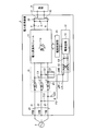
- FIG. 1 is a diagram showing a configuration of a power conversion device according to an embodiment of the present invention.
- FIG. 2 is a diagram showing a configuration of a modification of the power conversion device according to the embodiment of the present invention.
- FIG. 1 is a diagram showing a configuration of a power conversion device 1 according to an embodiment of the present invention.
- the power conversion device 1 includes a power conversion module 11 and a three-phase AC power line 20 including an R-phase power line 21, an S-phase power line 22, and a T-phase power line 23.
- the power converter 1 is supplied with three-phase AC power from an external three-phase AC power source 2.
- the supplied R-phase, S-phase, and T-phase power is supplied to the power conversion module 11 via the three-phase AC power line 20.
- the L-type filter 10 is provided in the three-phase AC power line 20.
- reactors L 1, L 2, and L 3 are respectively provided on the R-phase power line 21, the S-phase power line 22, and the T-phase power line 23, and between the R-phase power line 21, the S-phase power line 22, and the T-phase power line 23.
- filter capacitors C1, C2, and C3 are star-connected to each other.
- the L-type filter 10 is a low-pass filter and removes normal mode noise.
- the power conversion module 11 drives and controls the input three-phase AC power to the active element 11a such as a switching element, and converts it into desired power and outputs it.
- the active element 11a such as a switching element
- three-phase AC power is converted into DC power generated between PN.
- the power conversion module 11 functions as a converter.
- the power conversion module 11 may function as an AC-AC converter that converts three-phase AC power into AC power such as two-phase or three-phase.
- the power conversion module 11 may include a converter and an inverter.
- the power conversion module 11 may be a matrix converter.
- the DC power between PN output from the power conversion module 11 is supplied to a load 3 such as a DC motor provided outside via an output power line 30 including a P power line 31 and an N power line 32.
- the P power line 31 is provided with a reactor L.
- a capacitor C is provided between the P power line 31 and the N power line 32. Reactor L and capacitor C function as a low-pass filter.
- the drive control unit 15 drives and controls the active element 11a included in the power conversion module 11.
- the power supply unit 12 generates various control voltages necessary for drive control of the drive control unit 15 and supplies them to the drive control unit 15.
- the power supply line LN1 is wired between the point P1 on the T-phase power line 23 and the power supply unit 12.
- the point P1 may be on the R-phase power line 21 or on the S-phase power line 22.
- the power supply line LN2 is wired between the middle point P2 between the star-connected filter capacitors C1, C2, and C3 and the power supply unit 12.
- the power supply lines LN1 and LN2 are power supply lines LN that supply branch power obtained by branching a part of power from the three-phase AC power line 20 to the power supply unit 12.
- the power supply circuit 14 converts the input DC voltage into various control voltages necessary for drive control of the drive control unit 15 and supplies the converted control voltages to the drive control unit 15.
- the power supply circuit 14 is realized by, for example, a switching regulator.
- the voltage between the middle point P2 and each phase is 1 / ⁇ (3) of the line voltage of the three-phase AC power line 20. Therefore, the line voltage of the power supply line LN is 1 / ⁇ (3) of the line voltage of the three-phase AC power line 20.
- the line voltage of the power supply line LN is about 230V. Therefore, the breakdown voltage of the element in the power supply unit 12 can be reduced. Further, it is not necessary to take excessive insulation measures or provide a step-down circuit in the power supply unit 12. As a result, the power supply unit 12 can reduce the device scale and can be made inexpensive.
- the middle point P2 is between the star-connected filter capacitors constituting the existing L-type filter 10, the line of the three-phase AC power line 20 is the same as the neutral line of the three-phase four-wire AC power supply. A voltage about 1 / ⁇ (3) of the inter-voltage can be obtained. And since the neutral wire is not used, the structure for the noise countermeasure between the three-phase alternating current power supply 2 and the power converter device 1 becomes unnecessary for a neutral wire. For this reason, the noise removal component about a neutral line becomes unnecessary. Further, since the midpoint P2 is obtained by using the existing L-type filter 10, it is not necessary to add a special configuration and it is not necessary to increase the number of parts.
- the voltage (effective value) of the capacitor C3 was 226.4 V when C1 to C3 were 10 ⁇ F and the power used by the power supply unit 12 (power acquired from the T phase) was 31.1 W. Since the voltage (running value) when the acquired power from the T phase is zero is 230V, the voltage drop of the capacitor C3 is about 4V, and it has been found that the function of C3 as a filter is not impaired. .
- the midpoint P2 described above is a midpoint between the star-connected filter capacitors constituting the existing L-type filter 10.
- the present invention is not limited to this, and as shown in FIG. C23 may be provided to form the midpoint P3.
- the point P1 is provided on the T-phase power line 23, and two capacitors C22 and C23 connected in series are newly connected between the S-phase power line 22 and the T-phase power line 23.
- the midpoint P3 is the midpoint of the capacitors C22 and C23.
- the voltage at the midpoint P3 is 1 ⁇ 2 of the line voltage between the S-phase power line 22 and the T-phase power line 23.
- Capacitors C22 and C23 only need to be able to divide the line voltage of three-phase AC power line 20 into two, and when point P1 is provided on T-phase power line 23, between T-phase power line 23 and S-phase power line 22, or The T-phase power line 23 and the R-phase power line 21 are provided.
Landscapes
- Engineering & Computer Science (AREA)
- Power Engineering (AREA)
- Inverter Devices (AREA)
- Rectifiers (AREA)
- Power Conversion In General (AREA)
Abstract
入力された3相交流電力を所望電力出力状態に変換出力する電力変換モジュール(11)と電力変換モジュール(11)内のアクティブ素子(11a)を駆動する駆動制御部(15)と駆動制御部15で用いる電源電圧を生成して駆動制御部(15)に出力する電源部(12)とを有した電力変換装置(1)であって、入力された3相交流電力線(20)のT相電力線(23)と、3相交流電力線(20)にスター結線されたフィルタ用コンデンサ(C1)、(C2)、(C3)と、T相電力線(23)と電源部(12)との間およびフィルタ用コンデンサ(C1)、(C2)、(C3)間と電源部(12)との間にそれぞれ接続されて電源部(12)に電力供給する電源線(LN)を備える。
Description
本発明は、3相交流電源から電力変換装置の電源部に電力供給を受ける場合、降圧回路を不要にしたり、低い耐圧の素子を用いたりすることができると共に、ノイズ除去部品を減らすことができる電力変換装置に関する。
従来から、モータなどを負荷として運転制御する場合、コンバータやインバータなどの電力変換装置が用いられる。電力変換装置では、スイッチング素子などを駆動するための電源が必要となる。
特許文献1には、3相4線式交流電源の中性線とR相、S相、T相の3相の電力線のいずれか1つの相とに接続された電源配線を介して電力供給を受ける電源部を備えた電力変換装置を有する空気調和装置が記載されている。
また、特許文献2には、電力変換装置としてR相、S相、T相の3相の電力線のうちのいずれか2相から電力供給を受ける電源部を有する電動機制御装置が記載されている。
特許文献1に記載されたものは、中性線を有した3相4線式交流電源を空気調和装置の電力変換装置に接続するため、電力変換装置で発生したノイズが、中性線を含む4線すべてから外部(電源系統)へ漏れ出すため、電力変換装置と電源系統との間に、4線に対するノイズフィルタなどのノイズ除去部品が必要になる。
一方、特許文献2に記載されたものは、中性線を用いず、3相のうちのいずれか2相から電源を得るようにしている。ここで、電動機制御装置の電源部は、3相の線間電圧を所望の電源電圧に変換しなくてはならないが、一般に3相の線間電圧は200Vや400Vであり、高い電圧であるため、電源部の絶縁対策や電源部の素子の耐圧や降圧回路の付加などを考慮する必要がある。
本発明は、上記に鑑みてなされたものであって、3相交流電源から電力変換装置の電源部に電源供給を受ける場合、降圧回路を不要にしたり、低い耐圧の素子を用いたりすることができると共に、ノイズ除去部品を減らすことができる電力変換装置を提供することを目的とする。
上述した課題を解決し、目的を達成するために、本発明にかかる電力変換装置は、入力された3相交流電力を所望の電力に変換して出力する電力変換モジュールと前記電力変換モジュールに含まれるアクティブ素子を駆動する駆動制御部と前記駆動制御部で用いる電源電圧を生成して前記駆動制御部に出力する電源部とを有した電力変換装置であって、前記電力変換モジュールの前段に設けられ、前記電力変換モジュールの入力側に接続された3相交流電力を前記電力変換モジュールに出力する3相交流電力線と、前記3相交流電力線のうちのいずれか1相の電力線と他の1相の電力線との線間に直列接続された2つのコンデンサと、前記いずれか1相の電力線と前記電源部との間および前記2つのコンデンサ間と前記電源部との間にそれぞれ接続されて前記電源部に電力供給する電源線と、を備えたことを特徴とする。
また、本発明にかかる電力変換装置は、入力された3相交流電力を所望の電力に変換して出力する電力変換モジュールと前記電力変換モジュールに含まれるアクティブ素子を駆動する駆動制御部と前記駆動制御部で用いる電源電圧を生成して前記駆動制御部に出力する電源部とを有した電力変換装置であって、前記電力変換モジュールの前段に設けられ、前記電力変換モジュールの入力側に接続された3相交流電力を前記電力変換モジュールに出力する3相交流電力線と、前記3相交流電力線の間にスター結線された3つのフィルタ用コンデンサと、前記3相交流電力線のうちのいずれか1相の電力線と前記電源部との間および前記フィルタ用コンデンサ間と前記電源部との間にそれぞれ接続されて前記電源部に電力供給する電源線と、を備えたことを特徴とする。
本発明によれば、3相交流電源から電力変換装置の電源部に電源供給を受ける場合、電源線の線間電圧は3相の線間電圧の約半分の電圧となって降圧回路を不要にしたり、低い耐圧の素子を用いたりすることができ、しかも、3相4線式交流電源の中性線を用いていないので、4線全てにノイズ除去部品を用いる必要がなくなり、ノイズ除去部品を減らすることができる。
以下、添付図面を参照してこの発明を実施するための形態について説明する。
図1は、本発明の実施の形態である電力変換装置1の構成を示す図である。図1に示すように、電力変換装置1は、電力変換モジュール11とR相電力線21、S相電力線22、T相電力線23からなる3相交流電力線20とを備える。電力変換装置1には、外部の3相交流電源2から3相交流電力が供給される。供給されたR相、S相、T相の電力は、3相交流電力線20を経由して電力変換モジュール11に供給される。
3相交流電力線20には、L型フィルタ10が設けられている。L型フィルタ10は、R相電力線21、S相電力線22、T相電力線23に、それぞれリアクトルL1、L2、L3が設けられるとともに、R相電力線21、S相電力線22、T相電力線23の間にスター結線されたフィルタ用コンデンサC1、C2、C3が設けられる。L型フィルタ10は、ローパスフィルタであり、ノーマルモードノイズを除去する。
電力変換モジュール11は、入力される3相交流電力を、スイッチング素子などのアクティブ素子11aを駆動制御して所望の電力に変換して出力する。図1では、3相交流電力を、P-N間に発生する直流電力に変換している。図1では、電力変換モジュール11がコンバータとして機能しているが、3相交流電力を、2相あるいは3相などの交流電力に変換する交流―交流変換器として機能するものであってもよい。また、電力変換モジュール11は、コンバータとインバータとを含むものであってもよい。さらに、電力変換モジュール11は、マトリクスコンバータであってもよい。
電力変換モジュール11から出力されたP-N間の直流電力は、P電力線31とN電力線32とからなる出力電力線30を介して外部に設けられる直流モータなどの負荷3に供給される。なお、P電力線31にはリアクトルLが設けられる。また、P電力線31とN電力線32との線間にはコンデンサCが設けられる。リアクトルLとコンデンサCとは、ローパスフィルタとして機能する。
駆動制御部15は、電力変換モジュール11に含まれるアクティブ素子11aを駆動制御する。電源部12は、駆動制御部15の駆動制御に必要な各種の制御電圧を生成して駆動制御部15に供給する。
電源線LN1は、T相電力線23上の点P1と電源部12との間に配線される。なお、点P1は、R相電力線21上であってもよいし、S相電力線22上であってもよい。電源線LN2は、スター結線されたフィルタ用コンデンサC1、C2、C3間である中点P2と電源部12との間に配線される。電源線LN1、LN2は、3相交流電力線20から電力の一部を分岐した分岐電力を電源部12に供給する電源線LNである。
電源線LNを介して電源部12に供給された電力は交流であるため、全波整流回路13によって整流され、さらに、平滑コンデンサC4によって平滑され、直流電圧として電源回路14に入力される。電源回路14は、入力された直流電圧を、駆動制御部15の駆動制御に必要な各種の制御電圧に変換して駆動制御部15に供給する。電源回路14は、例えばスイッチングレギュレータなどによって実現される。
ここで、中点P2と各相の間の電圧は、3相交流電力線20の線間電圧の1/√(3)となる。したがって、電源線LNの線間電圧は3相交流電力線20の線間電圧の1/√(3)となる。例えば、3相交流電力線20の線間電圧が400V程度である場合、電源線LNの線間電圧は、230V程度となる。したがって、電源部12内の素子の耐圧を小さくすることができる。また、電源部12内に過度な絶縁対策を施したり、降圧回路を設けたりする必要がない。この結果、電源部12は、装置規模を小さくしたり、安価にすることができる。
また、中点P2は、既存のL型フィルタ10を構成するスター結線されたフィルタ用コンデンサ間であるため、3相4線式交流電源の中性線と同様に、3相交流電力線20の線間電圧の1/√(3)程度の電圧を得ることができる。しかも、中性線を用いていないので、3相交流電源2と電力変換装置1との間のノイズ対策のための構成が中性線には不要となる。このため、中性線についてのノイズ除去部品が不要となる。さらに、既存のL型フィルタ10を利用して中点P2を得るため、特別な構成を付加する必要がなく、部品を増やさずに済む。
中点P2として、既存のL型フィルタ10を構成するスター結線されたフィルタ用コンデンサの中点を利用した場合に、フィルタとしての機能が損なわれないことを確認するため、シミュレーションによる検証を行った。C1~C3を10μF、電源部12で使用する電力(T相から取得する電力)を31.1Wとしたとき、コンデンサC3の電圧(実効値)は226.4Vとなった。T相からの取得電力をゼロとしたときの電圧(実行値)が230Vであることから、コンデンサC3の電圧降下は4V程度であり、C3のフィルタとしての機能は損なわれていないことが分かった。
なお、上述した中点P2は、既存のL型フィルタ10を構成するスター結線されたフィルタ用コンデンサ間を中点としているが、これに限らず、図2に示すように、別途、コンデンサC22、C23を設けて中点P3を形成するようにしてもよい。図2では、図1と同様に、点P1をT相電力線23上に設けているとともに、直列接続した2つのコンデンサC22、C23をS相電力線22とT相電力線23との間に新たに接続し、中点P3をコンデンサC22とコンデンサC23の中点としている。この中点P3の電圧は、S相電力線22とT相電力線23との線間電圧の1/2となる。なお、コンデンサC22、C23は、3相交流電力線20の線間電圧を2分できればよく、点P1がT相電力線23に設けられた場合、T相電力線23とS相電力線22との間、または、T相電力線23とR相電力線21との間に設けられる。
なお、上述した点P1と中点P2、あるいは点P1と中点P3の位置から電源部12に必要な電源を供給しても、フィルタ用コンデンサC1、C2、C3の電圧波形に乱れはなく、フィルタ動作機能は損なわれていないことを確認している。
1 電力変換装置
2 3相交流電源
3 負荷
10 L型フィルタ
11 電力変換モジュール
11a アクティブ素子
12 電源部
13 全波整流回路
14 電源回路
15 駆動制御部
20 3相交流電力線
21 R相電力線
22 S相電力線
23 T相電力線
30 出力電力線
31 P電力線
32 N電力線
C,C22,C23 コンデンサ
C1 フィルタ用コンデンサ
C4 平滑コンデンサ
L,L1~L3 リアクトル
LN,LN1,LN2 電源線
P1 点
P2,P3 中点
2 3相交流電源
3 負荷
10 L型フィルタ
11 電力変換モジュール
11a アクティブ素子
12 電源部
13 全波整流回路
14 電源回路
15 駆動制御部
20 3相交流電力線
21 R相電力線
22 S相電力線
23 T相電力線
30 出力電力線
31 P電力線
32 N電力線
C,C22,C23 コンデンサ
C1 フィルタ用コンデンサ
C4 平滑コンデンサ
L,L1~L3 リアクトル
LN,LN1,LN2 電源線
P1 点
P2,P3 中点
Claims (2)
- 入力された3相交流電力を所望の電力に変換して出力する電力変換モジュールと前記電力変換モジュールに含まれるアクティブ素子を駆動する駆動制御部と前記駆動制御部で用いる電源電圧を生成して前記駆動制御部に出力する電源部とを有した電力変換装置であって、
前記電力変換モジュールの前段に設けられ、前記電力変換モジュールの入力側に接続された3相交流電力を前記電力変換モジュールに出力する3相交流電力線と、前記3相交流電力線のうちのいずれか1相の電力線と他の1相の電力線との線間に直列接続された2つのコンデンサと、
前記いずれか1相の電力線と前記電源部との間および前記2つのコンデンサ間と前記電源部との間にそれぞれ接続されて前記電源部に電力供給する電源線と、
を備えたことを特徴とする電力変換装置。 - 入力された3相交流電力を所望の電力に変換して出力する電力変換モジュールと前記電力変換モジュールに含まれるアクティブ素子を駆動する駆動制御部と前記駆動制御部で用いる電源電圧を生成して前記駆動制御部に出力する電源部とを有した電力変換装置であって、
前記電力変換モジュールの前段に設けられ、前記電力変換モジュールの入力側に接続された3相交流電力を前記電力変換モジュールに出力する3相交流電力線と、前記3相交流電力線の間にスター結線された3つのフィルタ用コンデンサと、
前記3相交流電力線のうちのいずれか1相の電力線と前記電源部との間および前記フィルタ用コンデンサ間と前記電源部との間にそれぞれ接続されて前記電源部に電力供給する電源線と、
を備えたことを特徴とする電力変換装置。
Priority Applications (3)
| Application Number | Priority Date | Filing Date | Title |
|---|---|---|---|
| CN201680062852.0A CN108377664B (zh) | 2015-10-30 | 2016-09-08 | 电力转换装置 |
| EP16859415.8A EP3370333B1 (en) | 2015-10-30 | 2016-09-08 | Power conversion device |
| AU2016345858A AU2016345858B2 (en) | 2015-10-30 | 2016-09-08 | Power converter |
Applications Claiming Priority (2)
| Application Number | Priority Date | Filing Date | Title |
|---|---|---|---|
| JP2015214497A JP6210102B2 (ja) | 2015-10-30 | 2015-10-30 | 電力変換装置 |
| JP2015-214497 | 2015-10-30 |
Publications (1)
| Publication Number | Publication Date |
|---|---|
| WO2017073178A1 true WO2017073178A1 (ja) | 2017-05-04 |
Family
ID=58630157
Family Applications (1)
| Application Number | Title | Priority Date | Filing Date |
|---|---|---|---|
| PCT/JP2016/076519 WO2017073178A1 (ja) | 2015-10-30 | 2016-09-08 | 電力変換装置 |
Country Status (5)
| Country | Link |
|---|---|
| EP (1) | EP3370333B1 (ja) |
| JP (1) | JP6210102B2 (ja) |
| CN (1) | CN108377664B (ja) |
| AU (1) | AU2016345858B2 (ja) |
| WO (1) | WO2017073178A1 (ja) |
Citations (4)
| Publication number | Priority date | Publication date | Assignee | Title |
|---|---|---|---|---|
| JPH07198154A (ja) * | 1994-01-12 | 1995-08-01 | Sanyo Electric Co Ltd | 空気調和装置 |
| JP2005337563A (ja) * | 2004-05-26 | 2005-12-08 | Daikin Ind Ltd | 電気機器 |
| JP2007202369A (ja) * | 2006-01-30 | 2007-08-09 | Yaskawa Electric Corp | マトリクスコンバータ装置 |
| JP2010148259A (ja) * | 2008-12-19 | 2010-07-01 | Yaskawa Electric Corp | フィルタ装置および電力変換装置 |
Family Cites Families (6)
| Publication number | Priority date | Publication date | Assignee | Title |
|---|---|---|---|---|
| CN2116294U (zh) * | 1992-03-24 | 1992-09-16 | 黄笃之 | 节能自动断相保护器 |
| JPH09285138A (ja) * | 1996-04-05 | 1997-10-31 | Matsushita Electric Ind Co Ltd | 電動機制御装置 |
| JP2007068311A (ja) * | 2005-08-30 | 2007-03-15 | Yaskawa Electric Corp | ノイズフィルタおよびモータ駆動装置 |
| US7808219B2 (en) * | 2007-11-26 | 2010-10-05 | Honeywell International Inc. | Method and apparatus of capacitor divider based offline AC-DC converter |
| JP5490612B2 (ja) * | 2010-05-27 | 2014-05-14 | 三洋電機株式会社 | 空気調和装置 |
| JP5062347B1 (ja) * | 2011-05-02 | 2012-10-31 | ダイキン工業株式会社 | 電力変換回路及び空気調和装置 |
-
2015
- 2015-10-30 JP JP2015214497A patent/JP6210102B2/ja active Active
-
2016
- 2016-09-08 WO PCT/JP2016/076519 patent/WO2017073178A1/ja active Application Filing
- 2016-09-08 EP EP16859415.8A patent/EP3370333B1/en active Active
- 2016-09-08 CN CN201680062852.0A patent/CN108377664B/zh active Active
- 2016-09-08 AU AU2016345858A patent/AU2016345858B2/en active Active
Patent Citations (4)
| Publication number | Priority date | Publication date | Assignee | Title |
|---|---|---|---|---|
| JPH07198154A (ja) * | 1994-01-12 | 1995-08-01 | Sanyo Electric Co Ltd | 空気調和装置 |
| JP2005337563A (ja) * | 2004-05-26 | 2005-12-08 | Daikin Ind Ltd | 電気機器 |
| JP2007202369A (ja) * | 2006-01-30 | 2007-08-09 | Yaskawa Electric Corp | マトリクスコンバータ装置 |
| JP2010148259A (ja) * | 2008-12-19 | 2010-07-01 | Yaskawa Electric Corp | フィルタ装置および電力変換装置 |
Also Published As
| Publication number | Publication date |
|---|---|
| CN108377664A (zh) | 2018-08-07 |
| EP3370333B1 (en) | 2020-05-06 |
| JP2017085845A (ja) | 2017-05-18 |
| CN108377664B (zh) | 2020-05-29 |
| EP3370333A1 (en) | 2018-09-05 |
| AU2016345858A1 (en) | 2018-05-10 |
| AU2016345858B2 (en) | 2020-03-19 |
| EP3370333A4 (en) | 2019-04-10 |
| JP6210102B2 (ja) | 2017-10-11 |
Similar Documents
| Publication | Publication Date | Title |
|---|---|---|
| JP4669723B2 (ja) | 電動機制御装置 | |
| US20080013352A1 (en) | Active rectifier system with power factor correction | |
| US5668457A (en) | Variable-frequency AC induction motor controller | |
| US20170272006A1 (en) | Power conversion apparatus; motor driving apparatus, blower, and compressor, each including same; and air conditioner, refrigerator, and freezer, each including at least one of them | |
| WO2017183426A1 (ja) | モータ駆動装置 | |
| JP2013110836A (ja) | 電力供給装置 | |
| JP4277186B2 (ja) | 電力変換器の制御装置 | |
| KR102406435B1 (ko) | 그리드 유형에 무관한 효율적인 dc 링크 처리를 위한 장치 | |
| JP2004248430A (ja) | 交流−交流電力変換器の制御装置 | |
| JP4479292B2 (ja) | 交流交流電力変換器の制御装置 | |
| JP6492031B2 (ja) | 電圧補償装置 | |
| JP6282378B2 (ja) | モータ駆動制御装置及び空気調和機 | |
| JP6432650B2 (ja) | 電力変換装置 | |
| JP6210102B2 (ja) | 電力変換装置 | |
| JP6091405B2 (ja) | エレベーターかご給電装置 | |
| KR102416374B1 (ko) | 고압인버터 전력셀의 직류단 전압 제어장치 | |
| JP2010110179A (ja) | 整流回路 | |
| JP5378244B2 (ja) | 電力変換装置 | |
| JP2009153297A (ja) | 自励式変換器の制御装置 | |
| JP3399288B2 (ja) | サイリスタ変換装置 | |
| RU2488213C1 (ru) | Многопульсное выпрямительное устройство и автотрансформатор | |
| JP2008043096A (ja) | 電力変換装置 | |
| JP2010283989A (ja) | 電力変換装置 | |
| JP3912596B2 (ja) | 交流−交流電力変換器の制御装置 | |
| JP6264091B2 (ja) | 交流−直流電力変換装置 |
Legal Events
| Date | Code | Title | Description |
|---|---|---|---|
| 121 | Ep: the epo has been informed by wipo that ep was designated in this application |
Ref document number: 16859415 Country of ref document: EP Kind code of ref document: A1 |
|
| NENP | Non-entry into the national phase |
Ref country code: DE |
|
| ENP | Entry into the national phase |
Ref document number: 2016345858 Country of ref document: AU Date of ref document: 20160908 Kind code of ref document: A |
|
| WWE | Wipo information: entry into national phase |
Ref document number: 2016859415 Country of ref document: EP |