WO2017073122A1 - 搬送システム - Google Patents
搬送システム Download PDFInfo
- Publication number
- WO2017073122A1 WO2017073122A1 PCT/JP2016/071243 JP2016071243W WO2017073122A1 WO 2017073122 A1 WO2017073122 A1 WO 2017073122A1 JP 2016071243 W JP2016071243 W JP 2016071243W WO 2017073122 A1 WO2017073122 A1 WO 2017073122A1
- Authority
- WO
- WIPO (PCT)
- Prior art keywords
- rack
- movable
- pinion
- teeth
- rack teeth
- Prior art date
- Legal status (The legal status is an assumption and is not a legal conclusion. Google has not performed a legal analysis and makes no representation as to the accuracy of the status listed.)
- Ceased
Links
Images


Classifications
-
- B—PERFORMING OPERATIONS; TRANSPORTING
- B61—RAILWAYS
- B61B—RAILWAY SYSTEMS; EQUIPMENT THEREFOR NOT OTHERWISE PROVIDED FOR
- B61B13/00—Other railway systems
- B61B13/02—Rack railways
-
- B—PERFORMING OPERATIONS; TRANSPORTING
- B61—RAILWAYS
- B61B—RAILWAY SYSTEMS; EQUIPMENT THEREFOR NOT OTHERWISE PROVIDED FOR
- B61B5/00—Elevated railway systems without suspended vehicles
-
- B—PERFORMING OPERATIONS; TRANSPORTING
- B62—LAND VEHICLES FOR TRAVELLING OTHERWISE THAN ON RAILS
- B62D—MOTOR VEHICLES; TRAILERS
- B62D65/00—Designing, manufacturing, e.g. assembling, facilitating disassembly, or structurally modifying motor vehicles or trailers, not otherwise provided for
- B62D65/02—Joining sub-units or components to, or positioning sub-units or components with respect to, body shell or other sub-units or components
- B62D65/18—Transportation, conveyor or haulage systems specially adapted for motor vehicle or trailer assembly lines
-
- B—PERFORMING OPERATIONS; TRANSPORTING
- B65—CONVEYING; PACKING; STORING; HANDLING THIN OR FILAMENTARY MATERIAL
- B65G—TRANSPORT OR STORAGE DEVICES, e.g. CONVEYORS FOR LOADING OR TIPPING, SHOP CONVEYOR SYSTEMS OR PNEUMATIC TUBE CONVEYORS
- B65G35/00—Mechanical conveyors not otherwise provided for
- B65G35/06—Mechanical conveyors not otherwise provided for comprising a load-carrier moving along a path, e.g. a closed path, and adapted to be engaged by any one of a series of traction elements spaced along the path
-
- B—PERFORMING OPERATIONS; TRANSPORTING
- B65—CONVEYING; PACKING; STORING; HANDLING THIN OR FILAMENTARY MATERIAL
- B65G—TRANSPORT OR STORAGE DEVICES, e.g. CONVEYORS FOR LOADING OR TIPPING, SHOP CONVEYOR SYSTEMS OR PNEUMATIC TUBE CONVEYORS
- B65G35/00—Mechanical conveyors not otherwise provided for
- B65G35/08—Mechanical conveyors not otherwise provided for comprising trains of unconnected load-carriers, e.g. belt sections, movable in a path, e.g. a closed path, adapted to contact each other and to be propelled by means arranged to engage each load-carrier in turn
-
- F—MECHANICAL ENGINEERING; LIGHTING; HEATING; WEAPONS; BLASTING
- F16—ENGINEERING ELEMENTS AND UNITS; GENERAL MEASURES FOR PRODUCING AND MAINTAINING EFFECTIVE FUNCTIONING OF MACHINES OR INSTALLATIONS; THERMAL INSULATION IN GENERAL
- F16H—GEARING
- F16H19/00—Gearings comprising essentially only toothed gears or friction members and not capable of conveying indefinitely-continuing rotary motion
- F16H19/02—Gearings comprising essentially only toothed gears or friction members and not capable of conveying indefinitely-continuing rotary motion for interconverting rotary or oscillating motion and reciprocating motion
- F16H19/04—Gearings comprising essentially only toothed gears or friction members and not capable of conveying indefinitely-continuing rotary motion for interconverting rotary or oscillating motion and reciprocating motion comprising a rack
-
- F—MECHANICAL ENGINEERING; LIGHTING; HEATING; WEAPONS; BLASTING
- F16—ENGINEERING ELEMENTS AND UNITS; GENERAL MEASURES FOR PRODUCING AND MAINTAINING EFFECTIVE FUNCTIONING OF MACHINES OR INSTALLATIONS; THERMAL INSULATION IN GENERAL
- F16H—GEARING
- F16H55/00—Elements with teeth or friction surfaces for conveying motion; Worms, pulleys or sheaves for gearing mechanisms
- F16H55/02—Toothed members; Worms
- F16H55/26—Racks
-
- F—MECHANICAL ENGINEERING; LIGHTING; HEATING; WEAPONS; BLASTING
- F16—ENGINEERING ELEMENTS AND UNITS; GENERAL MEASURES FOR PRODUCING AND MAINTAINING EFFECTIVE FUNCTIONING OF MACHINES OR INSTALLATIONS; THERMAL INSULATION IN GENERAL
- F16H—GEARING
- F16H19/00—Gearings comprising essentially only toothed gears or friction members and not capable of conveying indefinitely-continuing rotary motion
- F16H19/02—Gearings comprising essentially only toothed gears or friction members and not capable of conveying indefinitely-continuing rotary motion for interconverting rotary or oscillating motion and reciprocating motion
- F16H19/04—Gearings comprising essentially only toothed gears or friction members and not capable of conveying indefinitely-continuing rotary motion for interconverting rotary or oscillating motion and reciprocating motion comprising a rack
- F16H2019/046—Facilitating the engagement or stopping of racks
Definitions
- the present invention relates to a transport system in which a pinion is engaged with a rack provided on a moving body such as a transport cart and the mobile body such as a transport cart is moved by rotation of the pinion.
- a moving body is provided with a drive unit, a drive unit is provided on the transport path side, a plurality of moving bodies are connected and pulled, and travels.
- Various things, such as what makes a chain etc. engage / release, are well-known.
- a transport system that holds the automobile body etc. on a transport cart that is a moving body and transports various processes such as painting and drying together with the transport cart is provided with a rack on the transport cart.
- a transport system is known in which a pinion is arranged on the road side, the pinion is engaged with a rack provided on the transport cart, and the transport cart is moved by the rotation of the pinion (see, for example, Patent Document 1).
- the front end portion including the first teeth that first mesh with the pinion of the rack is a movable part (separate member), and the movable part (separate member) is supported swingably by a support shaft parallel to the rotation axis of the pinion.
- a conveyance system is known in which the support shaft is disposed behind the first teeth, and the movable portion (separate member) is swung to press the first teeth against the pinion (see, for example, Patent Document 3). .)
- the present invention solves these problems, and is configured only with a simple mechanical structure, and without causing malfunction, the phase and speed of adjacent pinions are different, or the phase of the pinion is changed due to a temperature change.
- a transport system is a transport system having a rack provided on a movable body and a pinion that engages with the rack and moves the movable body, and the rack includes a plurality of fixed rack teeth in the center. And a movable part provided with a movable rack tooth continuous to at least one end of the fixed rack tooth, and the movable part can swing around a support shaft part. The problem is solved by the support being provided and the support shaft portion being provided forward in the movement direction from the position where the movable rack teeth of the movable portion are present.
- a rack according to the present invention is a rack that engages with a pinion and moves by rotation of the pinion, and has a main body portion provided with a plurality of fixed rack teeth in the center, and at least one end portion of the fixed rack teeth.
- a movable portion having continuous movable rack teeth, and the movable portion is supported so as to be swingable about a support shaft portion, and the support shaft portion is located at a position where the movable rack teeth of the movable portion are present. The problem is solved by being provided forward in the movement direction.
- the support shaft portion is provided in front of the moving direction from the position where the movable rack teeth of the movable portion are present. Even if the phase and speed of the pinion teeth are different, the movable part is easily pushed upward by the rack teeth that first engage with the pinion tooth, and even if the moving speed of the rack is faster than the peripheral speed of the pinion, It is easily pushed upward without receiving a strong force and does not receive a strong pressing force in the moving direction.
- the movable part when the top of the tooth close to the support shaft is formed low, when the movable part is first pushed up by the rack tooth engaged with the pinion tooth, Since the angle can be reduced, the clearance above the movable portion can be reduced.
- the configuration of claim 3 when the movable part is provided at both front and rear ends in the moving direction of the main body part, when the peripheral speed of the front pinion is faster than the rear pinion, When the rack is engaged with the front pinion and the speed is increased, the movable part provided at the rear is pushed upward, so that the rack can be more reliably and sequentially engaged with and detached from the plurality of pinions. Become.
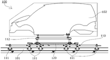
- the side view of the conveyance system which concerns on one Embodiment of this invention.
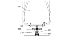
- the front view of the conveyance system which concerns on one Embodiment of this invention.
- the top view of a part of conveyance system concerning one embodiment of the present invention.
- the side view of the rack and pinion which concern on one Embodiment of this invention.
- the side view of the rack and pinion of the area which performs a continuous speed change.
- DESCRIPTION OF SYMBOLS 100 ... Transfer system 101 ... Rail 102 ... Automobile body (conveyed object) 110 ⁇ ⁇ ⁇ Transport cart (moving body) 111 ... Wheel 112 ... Car body support 120 ... Rack 121 ... Main body 122 ... Fixed rack teeth 123 ... Movable parts 124 ... Movable rack teeth 125 ... Support shaft parts 126 ... Movable part cover 130 ... Pinion 131 ... Pinion tooth 132 ... Rotating shaft
- a transport system 100 includes a car body 102 that is a transport object on a vehicle support base 112 that is provided above a transport cart 110 that is a moving body. Is configured to travel along the rail 101 by the wheels 111.
- a rack 120 extending in the moving direction is fixed to the transport carriage 110, and is engaged by engaging pinions (not shown) provided at predetermined intervals on the side of the rail 101 and rotating the pinions.
- the rack 120 to be driven is driven in the moving direction so that the transport carriage 110 moves.
- the structure of a conveyance trolley, a rail, and the support structure of a to-be-conveyed object may be what, for example, the structure in which a rail is provided upwards and a to-be-conveyed object is suspended with a conveyance truck may be sufficient.
- the transport mechanism of the transport carriage may be any type, such as a roller installed on the rail side that travels on the roller, or a magnetic levitation, air levitation, low friction surface sliding, etc. It may be.
- the transported object may be anything.
- the rack 120 has a main body portion 121 provided with a plurality of fixed rack teeth 122 at the center, and the front of the fixed rack teeth 122 in the moving direction (hereinafter simply referred to as “front”).
- a movable portion 123 provided with a movable rack tooth 124 continuous to the end portion, and a movable rack tooth 124b provided to the end portion of the fixed rack tooth 122 in the rearward movement direction (hereinafter simply referred to as “rearward”) are provided.
- a movable portion 123b is provided with a movable rack tooth 124 continuous to the end portion, and a movable rack tooth 124b provided to the end portion of the fixed rack tooth 122 in the rearward movement direction (hereinafter simply referred to as “rearward”) are provided.
- a movable portion 123b is provided with a movable rack tooth 124 continuous to the end portion, and a movable rack tooth 124b provided to the end portion of the fixed rack tooth 122 in the
- movable part covers 126 and 126b that also serve as a stopper function for restricting excessive jumping upward of the movable parts 123 and 123b are fixedly provided on the main body 121.
- the front movable portion 123 is supported to be swingable around a support shaft portion 125 provided on the front end portion side of the movable portion cover 126, and the rear movable portion 123b is supported on the main body 121 side of the movable portion cover 126b.
- the support shaft portion 125b is provided so as to be swingable around the support shaft portion 125b, and the support shaft portions 125 and 125b are both positioned in front of the positions where the movable rack teeth 124 and 124b of the movable portions 123 and 123b exist. Is configured to do. Further, the movable rack tooth 124 close to the support shaft portion 125 of the front movable portion 123 is formed with a low top portion.
- the front pinion 130 and the rear pinion 130 b have a distance between the rotation shafts 132 and 132 b at the forefront of the front movable portion 123.
- the distance between the top of the movable rack tooth 124 and the top of the rearmost movable rack tooth 124b of the movable part 123b is set substantially equal. For this reason, even when the phase of the foremost movable rack tooth 124 of the front movable part 123 and the pinion tooth 131 of the front pinion 130 is shifted, the front movable part 123 is pushed upward at the time of the first contact.
- the shock is relieved. After that, immediately after the engagement of the pinion teeth 131b of the rear pinion 130b and the rearmost movable rack teeth 124b of the rear movable portion 123b is released, the movable rack teeth 124 of the front movable portion 123 are moved to the pinion of the front pinion 130. Since it is in a position to engage with the teeth 131, the front and rear positions of the rack 120 are slightly shifted and the front movable portion 123 swings downward and engages accurately, and smoothly engages with the continuous fixed rack teeth 122. To do.
- a movable part cover 126 that also functions as a stopper that restricts excessive jumping upward of the movable part 123 is provided above the movable part 123. Colliding with various structures on the transfer line can be prevented. Further, the movable rack teeth 124 close to the support shaft portion 125 of the front movable portion 123 that first contacts the pinion teeth 131 of the front pinion 130 are formed with a low top, so that even if the phase is shifted, the amount of push-up is increased. , The height of the movable portion cover 126 is reduced, and the upper structure of the transport carriage 110 and various structures on the transport line are related to the mounting position of the rack 120 to the transport carriage 110 and the length of the rack 120. There are fewer restrictions due to things.
- the front pinion 130 and the rear pinion 130c are driven at different constant speeds.
- the speed is lowered, the movable rack teeth 124 of the front movable portion 123 abuts at a higher speed than the pinion teeth 131 of the front pinion 130, so that the speed of the transport carriage 110 is maintained while the speed is maintained.
- the front movable portion 123 is pushed upward without the rack teeth 124 and the pinion teeth 131 engaging.
- the speed of the transport carriage 110 decreases, and the movable rack tooth of the front movable part 123
- the speed and phase of 124 and the pinion teeth 131 of the front pinion 130 coincide with each other, and the front movable portion 123 swings downward and engages accurately.
- the front pinion 130 and the rear pinion 130 c are separated from each other by a distance between the rotation shafts 132 and 132 c so that the top and the rear of the frontmost movable rack tooth 124 of the front movable portion 123.
- the movable rack teeth 124 of the front movable portion 123 and the pinion teeth of the front pinion 130 are reduced.
- the movable rack teeth 124 of the front movable portion 123 abuts in a state where the speed is slower than the pinion teeth 131 of the front pinion 130. Therefore, depending on the timing, the movable rack teeth 124 and the pinion are at an early stage. The teeth 131 are engaged and the speed of the transport carriage 110 is increased. Even when the movable rack tooth 124b of the rear movable part 123b is engaged with the pinion tooth 131c of the rear pinion 130c when the speed of the transport carriage 110 is increased, the rear movable part 123b is not connected to the rear movable part cover.
- the support shaft portion 125b is swingably supported around the support shaft portion 125b provided on the main body portion 121 side of the 126b, and the support shaft portion 125b is positioned forward of the position where the movable rack teeth 124b of the rear movable portion 123b are present.
- the rear movable portion 123b is pushed upward to be disengaged, and the speed change of the transport carriage 110 can be smoothly performed.
- the distance between the front pinion 130d and the rear pinion 130e is the rear pinion.
- the front pinion teeth 131d are set to contact the fixed rack teeth 122 at the front end of the main body 121 of the rack 120. Yes.
- Such a section is a section in which it is required to accurately control the speed, transport direction, position, and the like of the transport carriage 110, and the speed and phase of the front pinion 130d and the rear pinion 130e are accurately controlled.
- the movable rack teeth 124 and 124b of the movable portions 123 and 123b at both ends do not need to operate, and the movable portion is always driven by the engagement of one of the pinion teeth 131d and 131e with the fixed rack teeth 122.
- Accurate speed, transport direction, position, and the like can be controlled without being affected by speed and position shifts associated with swinging of 123 and 123b.
- the present invention is not limited to the above-described embodiments, and various design changes can be made without departing from the present invention described in the claims. It is.
- the movable portions 123 and 123b that are engaged with the pinion 130 below the rack 120 and are pushed up are configured to return to their original positions due to gravity.
- the force to return to the original may be strengthened, or the pushing force may be lightened by energizing the reverse.
- the pinion may be engaged on the side or upper side of the rack. In that case, some biasing means for returning to the original position is essential.
- drive means other than the drive by the rack and pinion may be provided, and the drive means may be switched according to the necessary conveyance form. Furthermore, it is good also as a rack which provided the movable part only in the front or only back according to the aspect of conveyance.
- the shape of the rack teeth and pinion teeth may be any shape as long as they can be engaged and driven, and is a so-called “pin gear” in which the pinion is a sprocket and the pins are arranged at equal intervals on the rack side. There may be.
Landscapes
- Engineering & Computer Science (AREA)
- Mechanical Engineering (AREA)
- General Engineering & Computer Science (AREA)
- Transportation (AREA)
- Manufacturing & Machinery (AREA)
- Chemical & Material Sciences (AREA)
- Combustion & Propulsion (AREA)
- Transmission Devices (AREA)
- Automobile Manufacture Line, Endless Track Vehicle, Trailer (AREA)
- Types And Forms Of Lifts (AREA)
Priority Applications (4)
| Application Number | Priority Date | Filing Date | Title |
|---|---|---|---|
| MYPI2018000547A MY188583A (en) | 2015-10-29 | 2016-07-20 | Conveyance system |
| CN201680061344.0A CN108349660B (zh) | 2015-10-29 | 2016-07-20 | 搬运系统 |
| MX2018004726A MX2018004726A (es) | 2015-10-29 | 2016-07-20 | Sistema de transporte. |
| US15/956,872 US20180237034A1 (en) | 2015-10-29 | 2018-04-19 | Conveyance system |
Applications Claiming Priority (2)
| Application Number | Priority Date | Filing Date | Title |
|---|---|---|---|
| JP2015-212499 | 2015-10-29 | ||
| JP2015212499A JP6192240B2 (ja) | 2015-10-29 | 2015-10-29 | 搬送システム |
Related Child Applications (1)
| Application Number | Title | Priority Date | Filing Date |
|---|---|---|---|
| US15/956,872 Continuation US20180237034A1 (en) | 2015-10-29 | 2018-04-19 | Conveyance system |
Publications (1)
| Publication Number | Publication Date |
|---|---|
| WO2017073122A1 true WO2017073122A1 (ja) | 2017-05-04 |
Family
ID=58631443
Family Applications (1)
| Application Number | Title | Priority Date | Filing Date |
|---|---|---|---|
| PCT/JP2016/071243 Ceased WO2017073122A1 (ja) | 2015-10-29 | 2016-07-20 | 搬送システム |
Country Status (6)
| Country | Link |
|---|---|
| US (1) | US20180237034A1 (enExample) |
| JP (1) | JP6192240B2 (enExample) |
| CN (1) | CN108349660B (enExample) |
| MX (1) | MX2018004726A (enExample) |
| MY (1) | MY188583A (enExample) |
| WO (1) | WO2017073122A1 (enExample) |
Families Citing this family (9)
| Publication number | Priority date | Publication date | Assignee | Title |
|---|---|---|---|---|
| CN109761011A (zh) * | 2017-11-09 | 2019-05-17 | 中西金属工业株式会社 | 输送装置 |
| CN109677837B (zh) * | 2019-01-07 | 2020-06-26 | 安徽理工大学 | 一种可控磁电混合悬浮磁垫带式运输机及其控制电路 |
| CN111731993B (zh) * | 2019-03-25 | 2022-05-03 | 太原理工大学 | 一种轨道用复合驱动转换装置及其轨道系统 |
| CN110194234A (zh) * | 2019-05-05 | 2019-09-03 | 广州明珞汽车装备有限公司 | 往复式牵引机构 |
| CN110203596B (zh) * | 2019-05-05 | 2021-04-27 | 广州明珞汽车装备有限公司 | 夹具切换系统 |
| CN110439343B (zh) * | 2019-08-30 | 2024-05-21 | 中国人民解放军陆军工程大学 | 一种立体停车装置 |
| JP7712545B2 (ja) * | 2021-09-15 | 2025-07-24 | 伊藤 涼子 | 炭化油化処理装置 |
| CN116588620B (zh) * | 2022-02-07 | 2025-12-09 | 泰科电子(上海)有限公司 | 载具传输系统、传输系统和载具传输方法 |
| JP7453568B2 (ja) * | 2022-02-08 | 2024-03-21 | 株式会社椿本チエイン | 搬送システム |
Citations (4)
| Publication number | Priority date | Publication date | Assignee | Title |
|---|---|---|---|---|
| JPS4862446U (enExample) * | 1971-11-22 | 1973-08-08 | ||
| JPH0914375A (ja) * | 1995-06-29 | 1997-01-14 | Sharp Corp | 駆動力伝達装置 |
| JPH09266522A (ja) * | 1996-03-28 | 1997-10-07 | Seiko Epson Corp | 原稿装着装置 |
| JP2006038190A (ja) * | 2004-07-30 | 2006-02-09 | Sumitomo Electric Hardmetal Corp | ラックピニオン装置 |
Family Cites Families (10)
| Publication number | Priority date | Publication date | Assignee | Title |
|---|---|---|---|---|
| GB436082A (en) * | 1934-03-28 | 1935-09-30 | William Mackey Stavers | Improvements in rack and pinion mechanism |
| US2376161A (en) * | 1944-01-17 | 1945-05-15 | Selas Corp Of America | Tooth gearing |
| US2410643A (en) * | 1944-10-17 | 1946-11-05 | Fielding Charles Stuart | Rack and pinion mechanism |
| US3443449A (en) * | 1967-10-16 | 1969-05-13 | Ritter Pfaudler Corp | Gear engagement device |
| JPS52117531U (enExample) * | 1976-03-03 | 1977-09-06 | ||
| JP2509486Y2 (ja) * | 1989-07-31 | 1996-09-04 | 中西金属工業株式会社 | キャリヤ自走式コンベヤ |
| DE29801025U1 (de) * | 1998-01-26 | 1998-03-19 | C. Rob. Hammerstein GmbH & Co. KG, 42699 Solingen | Verstellvorrichtung für Fahrzeugsitze mit einem Verzahnungsteil und einem Antriebs- oder Abtriebsteil |
| US20040107787A1 (en) * | 2002-12-04 | 2004-06-10 | Bernard Petrillo | Backlash-free rack and pinion |
| US9487233B2 (en) * | 2014-07-14 | 2016-11-08 | Deere & Company | Steering gear pad |
| JP6429029B2 (ja) * | 2015-12-01 | 2018-11-28 | 株式会社ダイフク | ラックギヤ駆動可能な搬送装置 |
-
2015
- 2015-10-29 JP JP2015212499A patent/JP6192240B2/ja active Active
-
2016
- 2016-07-20 CN CN201680061344.0A patent/CN108349660B/zh active Active
- 2016-07-20 MY MYPI2018000547A patent/MY188583A/en unknown
- 2016-07-20 MX MX2018004726A patent/MX2018004726A/es unknown
- 2016-07-20 WO PCT/JP2016/071243 patent/WO2017073122A1/ja not_active Ceased
-
2018
- 2018-04-19 US US15/956,872 patent/US20180237034A1/en not_active Abandoned
Patent Citations (4)
| Publication number | Priority date | Publication date | Assignee | Title |
|---|---|---|---|---|
| JPS4862446U (enExample) * | 1971-11-22 | 1973-08-08 | ||
| JPH0914375A (ja) * | 1995-06-29 | 1997-01-14 | Sharp Corp | 駆動力伝達装置 |
| JPH09266522A (ja) * | 1996-03-28 | 1997-10-07 | Seiko Epson Corp | 原稿装着装置 |
| JP2006038190A (ja) * | 2004-07-30 | 2006-02-09 | Sumitomo Electric Hardmetal Corp | ラックピニオン装置 |
Also Published As
| Publication number | Publication date |
|---|---|
| CN108349660A (zh) | 2018-07-31 |
| MY188583A (en) | 2021-12-22 |
| JP2017081703A (ja) | 2017-05-18 |
| MX2018004726A (es) | 2018-07-06 |
| US20180237034A1 (en) | 2018-08-23 |
| JP6192240B2 (ja) | 2017-09-06 |
| CN108349660B (zh) | 2020-07-10 |
Similar Documents
| Publication | Publication Date | Title |
|---|---|---|
| JP6192240B2 (ja) | 搬送システム | |
| KR101980293B1 (ko) | 사이드 아암식 이재 장치 | |
| JP5828241B2 (ja) | コンベア装置 | |
| JP2017081703A5 (enExample) | ||
| JP6379982B2 (ja) | 搬送装置 | |
| DK3016894T3 (da) | Vippeskåltransportvogn og vippeskålsorteringsanlæg | |
| JP5745920B2 (ja) | 搬送装置および搬送方法 | |
| JP6332753B2 (ja) | 台車式搬送装置 | |
| TW201206796A (en) | Automated warehouse system and release braking means thereof | |
| JP2013107731A (ja) | コンベア装置 | |
| CN109368301A (zh) | 用于物料装车的推拉装置 | |
| CN105417046A (zh) | 一种双向轨道输送装置 | |
| US795124A (en) | Car-haul. | |
| CN102161425A (zh) | 输送机装置 | |
| US20170022014A1 (en) | Conveying-Traveling-Body-Utilizing Conveying Device | |
| SE510119C2 (sv) | Sätt och anordning för vändning av brädor | |
| JP2013159469A (ja) | 物品搬送仕分け装置 | |
| JP5467681B2 (ja) | 搬送装置 | |
| CA2915545C (en) | Safety chain for aisle pallets for transporting people and goods | |
| JP2000510802A (ja) | 棚状貯蔵システムの棚状チャンネル用搬送装置 | |
| JP5618696B2 (ja) | 乗客コンベア | |
| JP6206702B2 (ja) | 搬送装置 | |
| US20170088148A1 (en) | Transport device for transporting goods | |
| BE526055A (enExample) | ||
| US1098725A (en) | Power-ramp. |
Legal Events
| Date | Code | Title | Description |
|---|---|---|---|
| 121 | Ep: the epo has been informed by wipo that ep was designated in this application |
Ref document number: 16859359 Country of ref document: EP Kind code of ref document: A1 |
|
| WWE | Wipo information: entry into national phase |
Ref document number: MX/A/2018/004726 Country of ref document: MX |
|
| NENP | Non-entry into the national phase |
Ref country code: DE |
|
| 122 | Ep: pct application non-entry in european phase |
Ref document number: 16859359 Country of ref document: EP Kind code of ref document: A1 |