WO2017073122A1 - Conveyance system - Google Patents
Conveyance system Download PDFInfo
- Publication number
- WO2017073122A1 WO2017073122A1 PCT/JP2016/071243 JP2016071243W WO2017073122A1 WO 2017073122 A1 WO2017073122 A1 WO 2017073122A1 JP 2016071243 W JP2016071243 W JP 2016071243W WO 2017073122 A1 WO2017073122 A1 WO 2017073122A1
- Authority
- WO
- WIPO (PCT)
- Prior art keywords
- rack
- movable
- pinion
- teeth
- rack teeth
- Prior art date
Links
Images


Classifications
-
- B—PERFORMING OPERATIONS; TRANSPORTING
- B61—RAILWAYS
- B61B—RAILWAY SYSTEMS; EQUIPMENT THEREFOR NOT OTHERWISE PROVIDED FOR
- B61B13/00—Other railway systems
- B61B13/02—Rack railways
-
- B—PERFORMING OPERATIONS; TRANSPORTING
- B61—RAILWAYS
- B61B—RAILWAY SYSTEMS; EQUIPMENT THEREFOR NOT OTHERWISE PROVIDED FOR
- B61B5/00—Elevated railway systems without suspended vehicles
-
- B—PERFORMING OPERATIONS; TRANSPORTING
- B62—LAND VEHICLES FOR TRAVELLING OTHERWISE THAN ON RAILS
- B62D—MOTOR VEHICLES; TRAILERS
- B62D65/00—Designing, manufacturing, e.g. assembling, facilitating disassembly, or structurally modifying motor vehicles or trailers, not otherwise provided for
- B62D65/02—Joining sub-units or components to, or positioning sub-units or components with respect to, body shell or other sub-units or components
- B62D65/18—Transportation, conveyor or haulage systems specially adapted for motor vehicle or trailer assembly lines
-
- B—PERFORMING OPERATIONS; TRANSPORTING
- B65—CONVEYING; PACKING; STORING; HANDLING THIN OR FILAMENTARY MATERIAL
- B65G—TRANSPORT OR STORAGE DEVICES, e.g. CONVEYORS FOR LOADING OR TIPPING, SHOP CONVEYOR SYSTEMS OR PNEUMATIC TUBE CONVEYORS
- B65G35/00—Mechanical conveyors not otherwise provided for
- B65G35/06—Mechanical conveyors not otherwise provided for comprising a load-carrier moving along a path, e.g. a closed path, and adapted to be engaged by any one of a series of traction elements spaced along the path
-
- B—PERFORMING OPERATIONS; TRANSPORTING
- B65—CONVEYING; PACKING; STORING; HANDLING THIN OR FILAMENTARY MATERIAL
- B65G—TRANSPORT OR STORAGE DEVICES, e.g. CONVEYORS FOR LOADING OR TIPPING, SHOP CONVEYOR SYSTEMS OR PNEUMATIC TUBE CONVEYORS
- B65G35/00—Mechanical conveyors not otherwise provided for
- B65G35/08—Mechanical conveyors not otherwise provided for comprising trains of unconnected load-carriers, e.g. belt sections, movable in a path, e.g. a closed path, adapted to contact each other and to be propelled by means arranged to engage each load-carrier in turn
-
- F—MECHANICAL ENGINEERING; LIGHTING; HEATING; WEAPONS; BLASTING
- F16—ENGINEERING ELEMENTS AND UNITS; GENERAL MEASURES FOR PRODUCING AND MAINTAINING EFFECTIVE FUNCTIONING OF MACHINES OR INSTALLATIONS; THERMAL INSULATION IN GENERAL
- F16H—GEARING
- F16H19/00—Gearings comprising essentially only toothed gears or friction members and not capable of conveying indefinitely-continuing rotary motion
- F16H19/02—Gearings comprising essentially only toothed gears or friction members and not capable of conveying indefinitely-continuing rotary motion for interconverting rotary or oscillating motion and reciprocating motion
- F16H19/04—Gearings comprising essentially only toothed gears or friction members and not capable of conveying indefinitely-continuing rotary motion for interconverting rotary or oscillating motion and reciprocating motion comprising a rack
-
- F—MECHANICAL ENGINEERING; LIGHTING; HEATING; WEAPONS; BLASTING
- F16—ENGINEERING ELEMENTS AND UNITS; GENERAL MEASURES FOR PRODUCING AND MAINTAINING EFFECTIVE FUNCTIONING OF MACHINES OR INSTALLATIONS; THERMAL INSULATION IN GENERAL
- F16H—GEARING
- F16H55/00—Elements with teeth or friction surfaces for conveying motion; Worms, pulleys or sheaves for gearing mechanisms
- F16H55/02—Toothed members; Worms
- F16H55/26—Racks
-
- F—MECHANICAL ENGINEERING; LIGHTING; HEATING; WEAPONS; BLASTING
- F16—ENGINEERING ELEMENTS AND UNITS; GENERAL MEASURES FOR PRODUCING AND MAINTAINING EFFECTIVE FUNCTIONING OF MACHINES OR INSTALLATIONS; THERMAL INSULATION IN GENERAL
- F16H—GEARING
- F16H19/00—Gearings comprising essentially only toothed gears or friction members and not capable of conveying indefinitely-continuing rotary motion
- F16H19/02—Gearings comprising essentially only toothed gears or friction members and not capable of conveying indefinitely-continuing rotary motion for interconverting rotary or oscillating motion and reciprocating motion
- F16H19/04—Gearings comprising essentially only toothed gears or friction members and not capable of conveying indefinitely-continuing rotary motion for interconverting rotary or oscillating motion and reciprocating motion comprising a rack
- F16H2019/046—Facilitating the engagement or stopping of racks
Definitions
- the present invention relates to a transport system in which a pinion is engaged with a rack provided on a moving body such as a transport cart and the mobile body such as a transport cart is moved by rotation of the pinion.
- a moving body is provided with a drive unit, a drive unit is provided on the transport path side, a plurality of moving bodies are connected and pulled, and travels.
- Various things, such as what makes a chain etc. engage / release, are well-known.
- a transport system that holds the automobile body etc. on a transport cart that is a moving body and transports various processes such as painting and drying together with the transport cart is provided with a rack on the transport cart.
- a transport system is known in which a pinion is arranged on the road side, the pinion is engaged with a rack provided on the transport cart, and the transport cart is moved by the rotation of the pinion (see, for example, Patent Document 1).
- the front end portion including the first teeth that first mesh with the pinion of the rack is a movable part (separate member), and the movable part (separate member) is supported swingably by a support shaft parallel to the rotation axis of the pinion.
- a conveyance system is known in which the support shaft is disposed behind the first teeth, and the movable portion (separate member) is swung to press the first teeth against the pinion (see, for example, Patent Document 3). .)
- the present invention solves these problems, and is configured only with a simple mechanical structure, and without causing malfunction, the phase and speed of adjacent pinions are different, or the phase of the pinion is changed due to a temperature change.
- a transport system is a transport system having a rack provided on a movable body and a pinion that engages with the rack and moves the movable body, and the rack includes a plurality of fixed rack teeth in the center. And a movable part provided with a movable rack tooth continuous to at least one end of the fixed rack tooth, and the movable part can swing around a support shaft part. The problem is solved by the support being provided and the support shaft portion being provided forward in the movement direction from the position where the movable rack teeth of the movable portion are present.
- a rack according to the present invention is a rack that engages with a pinion and moves by rotation of the pinion, and has a main body portion provided with a plurality of fixed rack teeth in the center, and at least one end portion of the fixed rack teeth.
- a movable portion having continuous movable rack teeth, and the movable portion is supported so as to be swingable about a support shaft portion, and the support shaft portion is located at a position where the movable rack teeth of the movable portion are present. The problem is solved by being provided forward in the movement direction.
- the support shaft portion is provided in front of the moving direction from the position where the movable rack teeth of the movable portion are present. Even if the phase and speed of the pinion teeth are different, the movable part is easily pushed upward by the rack teeth that first engage with the pinion tooth, and even if the moving speed of the rack is faster than the peripheral speed of the pinion, It is easily pushed upward without receiving a strong force and does not receive a strong pressing force in the moving direction.
- the movable part when the top of the tooth close to the support shaft is formed low, when the movable part is first pushed up by the rack tooth engaged with the pinion tooth, Since the angle can be reduced, the clearance above the movable portion can be reduced.
- the configuration of claim 3 when the movable part is provided at both front and rear ends in the moving direction of the main body part, when the peripheral speed of the front pinion is faster than the rear pinion, When the rack is engaged with the front pinion and the speed is increased, the movable part provided at the rear is pushed upward, so that the rack can be more reliably and sequentially engaged with and detached from the plurality of pinions. Become.
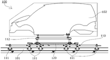
- the side view of the conveyance system which concerns on one Embodiment of this invention.
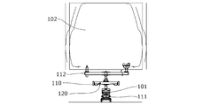
- the front view of the conveyance system which concerns on one Embodiment of this invention.
- the top view of a part of conveyance system concerning one embodiment of the present invention.
- the side view of the rack and pinion which concern on one Embodiment of this invention.
- the side view of the rack and pinion of the area which performs a continuous speed change.
- DESCRIPTION OF SYMBOLS 100 ... Transfer system 101 ... Rail 102 ... Automobile body (conveyed object) 110 ⁇ ⁇ ⁇ Transport cart (moving body) 111 ... Wheel 112 ... Car body support 120 ... Rack 121 ... Main body 122 ... Fixed rack teeth 123 ... Movable parts 124 ... Movable rack teeth 125 ... Support shaft parts 126 ... Movable part cover 130 ... Pinion 131 ... Pinion tooth 132 ... Rotating shaft
- a transport system 100 includes a car body 102 that is a transport object on a vehicle support base 112 that is provided above a transport cart 110 that is a moving body. Is configured to travel along the rail 101 by the wheels 111.
- a rack 120 extending in the moving direction is fixed to the transport carriage 110, and is engaged by engaging pinions (not shown) provided at predetermined intervals on the side of the rail 101 and rotating the pinions.
- the rack 120 to be driven is driven in the moving direction so that the transport carriage 110 moves.
- the structure of a conveyance trolley, a rail, and the support structure of a to-be-conveyed object may be what, for example, the structure in which a rail is provided upwards and a to-be-conveyed object is suspended with a conveyance truck may be sufficient.
- the transport mechanism of the transport carriage may be any type, such as a roller installed on the rail side that travels on the roller, or a magnetic levitation, air levitation, low friction surface sliding, etc. It may be.
- the transported object may be anything.
- the rack 120 has a main body portion 121 provided with a plurality of fixed rack teeth 122 at the center, and the front of the fixed rack teeth 122 in the moving direction (hereinafter simply referred to as “front”).
- a movable portion 123 provided with a movable rack tooth 124 continuous to the end portion, and a movable rack tooth 124b provided to the end portion of the fixed rack tooth 122 in the rearward movement direction (hereinafter simply referred to as “rearward”) are provided.
- a movable portion 123b is provided with a movable rack tooth 124 continuous to the end portion, and a movable rack tooth 124b provided to the end portion of the fixed rack tooth 122 in the rearward movement direction (hereinafter simply referred to as “rearward”) are provided.
- a movable portion 123b is provided with a movable rack tooth 124 continuous to the end portion, and a movable rack tooth 124b provided to the end portion of the fixed rack tooth 122 in the
- movable part covers 126 and 126b that also serve as a stopper function for restricting excessive jumping upward of the movable parts 123 and 123b are fixedly provided on the main body 121.
- the front movable portion 123 is supported to be swingable around a support shaft portion 125 provided on the front end portion side of the movable portion cover 126, and the rear movable portion 123b is supported on the main body 121 side of the movable portion cover 126b.
- the support shaft portion 125b is provided so as to be swingable around the support shaft portion 125b, and the support shaft portions 125 and 125b are both positioned in front of the positions where the movable rack teeth 124 and 124b of the movable portions 123 and 123b exist. Is configured to do. Further, the movable rack tooth 124 close to the support shaft portion 125 of the front movable portion 123 is formed with a low top portion.
- the front pinion 130 and the rear pinion 130 b have a distance between the rotation shafts 132 and 132 b at the forefront of the front movable portion 123.
- the distance between the top of the movable rack tooth 124 and the top of the rearmost movable rack tooth 124b of the movable part 123b is set substantially equal. For this reason, even when the phase of the foremost movable rack tooth 124 of the front movable part 123 and the pinion tooth 131 of the front pinion 130 is shifted, the front movable part 123 is pushed upward at the time of the first contact.
- the shock is relieved. After that, immediately after the engagement of the pinion teeth 131b of the rear pinion 130b and the rearmost movable rack teeth 124b of the rear movable portion 123b is released, the movable rack teeth 124 of the front movable portion 123 are moved to the pinion of the front pinion 130. Since it is in a position to engage with the teeth 131, the front and rear positions of the rack 120 are slightly shifted and the front movable portion 123 swings downward and engages accurately, and smoothly engages with the continuous fixed rack teeth 122. To do.
- a movable part cover 126 that also functions as a stopper that restricts excessive jumping upward of the movable part 123 is provided above the movable part 123. Colliding with various structures on the transfer line can be prevented. Further, the movable rack teeth 124 close to the support shaft portion 125 of the front movable portion 123 that first contacts the pinion teeth 131 of the front pinion 130 are formed with a low top, so that even if the phase is shifted, the amount of push-up is increased. , The height of the movable portion cover 126 is reduced, and the upper structure of the transport carriage 110 and various structures on the transport line are related to the mounting position of the rack 120 to the transport carriage 110 and the length of the rack 120. There are fewer restrictions due to things.
- the front pinion 130 and the rear pinion 130c are driven at different constant speeds.
- the speed is lowered, the movable rack teeth 124 of the front movable portion 123 abuts at a higher speed than the pinion teeth 131 of the front pinion 130, so that the speed of the transport carriage 110 is maintained while the speed is maintained.
- the front movable portion 123 is pushed upward without the rack teeth 124 and the pinion teeth 131 engaging.
- the speed of the transport carriage 110 decreases, and the movable rack tooth of the front movable part 123
- the speed and phase of 124 and the pinion teeth 131 of the front pinion 130 coincide with each other, and the front movable portion 123 swings downward and engages accurately.
- the front pinion 130 and the rear pinion 130 c are separated from each other by a distance between the rotation shafts 132 and 132 c so that the top and the rear of the frontmost movable rack tooth 124 of the front movable portion 123.
- the movable rack teeth 124 of the front movable portion 123 and the pinion teeth of the front pinion 130 are reduced.
- the movable rack teeth 124 of the front movable portion 123 abuts in a state where the speed is slower than the pinion teeth 131 of the front pinion 130. Therefore, depending on the timing, the movable rack teeth 124 and the pinion are at an early stage. The teeth 131 are engaged and the speed of the transport carriage 110 is increased. Even when the movable rack tooth 124b of the rear movable part 123b is engaged with the pinion tooth 131c of the rear pinion 130c when the speed of the transport carriage 110 is increased, the rear movable part 123b is not connected to the rear movable part cover.
- the support shaft portion 125b is swingably supported around the support shaft portion 125b provided on the main body portion 121 side of the 126b, and the support shaft portion 125b is positioned forward of the position where the movable rack teeth 124b of the rear movable portion 123b are present.
- the rear movable portion 123b is pushed upward to be disengaged, and the speed change of the transport carriage 110 can be smoothly performed.
- the distance between the front pinion 130d and the rear pinion 130e is the rear pinion.
- the front pinion teeth 131d are set to contact the fixed rack teeth 122 at the front end of the main body 121 of the rack 120. Yes.
- Such a section is a section in which it is required to accurately control the speed, transport direction, position, and the like of the transport carriage 110, and the speed and phase of the front pinion 130d and the rear pinion 130e are accurately controlled.
- the movable rack teeth 124 and 124b of the movable portions 123 and 123b at both ends do not need to operate, and the movable portion is always driven by the engagement of one of the pinion teeth 131d and 131e with the fixed rack teeth 122.
- Accurate speed, transport direction, position, and the like can be controlled without being affected by speed and position shifts associated with swinging of 123 and 123b.
- the present invention is not limited to the above-described embodiments, and various design changes can be made without departing from the present invention described in the claims. It is.
- the movable portions 123 and 123b that are engaged with the pinion 130 below the rack 120 and are pushed up are configured to return to their original positions due to gravity.
- the force to return to the original may be strengthened, or the pushing force may be lightened by energizing the reverse.
- the pinion may be engaged on the side or upper side of the rack. In that case, some biasing means for returning to the original position is essential.
- drive means other than the drive by the rack and pinion may be provided, and the drive means may be switched according to the necessary conveyance form. Furthermore, it is good also as a rack which provided the movable part only in the front or only back according to the aspect of conveyance.
- the shape of the rack teeth and pinion teeth may be any shape as long as they can be engaged and driven, and is a so-called “pin gear” in which the pinion is a sprocket and the pins are arranged at equal intervals on the rack side. There may be.
Landscapes
- Engineering & Computer Science (AREA)
- Mechanical Engineering (AREA)
- General Engineering & Computer Science (AREA)
- Transportation (AREA)
- Manufacturing & Machinery (AREA)
- Chemical & Material Sciences (AREA)
- Combustion & Propulsion (AREA)
- Transmission Devices (AREA)
- Automobile Manufacture Line, Endless Track Vehicle, Trailer (AREA)
- Types And Forms Of Lifts (AREA)
Abstract
The purpose of the present invention is to provide a conveyance system and a rack, the conveyance system being configured only by a simple mechanical structure and causing no malfunctions, and the rack being able to reliably and sequentially engage with/disengage from a plurality of pinions without being stopped or damaged, while shock, vibration, noise or the like is suppressed even if the pinions differ in phase and speed or are shifted in phase by temperature changes. The rack (120) comprises: a body portion (121) which is provided with a plurality of fixed rack teeth (122) in the center; and a movable portion (123) which is provided with movable rack teeth (124) that are continuous with at least one end of the fixed rack teeth (122). The movable portion (123) is supported so as to be rockable about a support shaft (125) which is provided further forward in the movement direction than the position where the movable rack teeth (124) of the movable portion (123) are located.
Description
本発明は、搬送台車等の移動体に設けられたラックにピニオンを係合させ、ピニオンの回転によって搬送台車等の移動体を移動させる搬送システムに関する。
The present invention relates to a transport system in which a pinion is engaged with a rack provided on a moving body such as a transport cart and the mobile body such as a transport cart is moved by rotation of the pinion.
搬送台車等の移動体を搬送する搬送システムでは、移動のための、移動体に駆動部を設けるもの、搬送路側に駆動部を設けるもの、複数の移動体を連結して牽引するもの、走行するチェーン等に係合離脱させるもの等、様々なものが公知である。
例えば、自動車ボディ等に塗装を施すため、自動車ボディ等を移動体である搬送台車に保持し、搬送台車ごと塗装、乾燥等の諸工程を搬送する搬送システムでは、搬送台車にラックを設け、搬送路側にピニオンを配置し、搬送台車に設けられたラックにピニオンを係合させ、ピニオンの回転によって搬送台車を移動させる搬送システムが公知である(例えば、特許文献1等参照。)。 In a transport system for transporting a moving body such as a transport carriage, a moving body is provided with a drive unit, a drive unit is provided on the transport path side, a plurality of moving bodies are connected and pulled, and travels. Various things, such as what makes a chain etc. engage / release, are well-known.
For example, in order to apply paint to an automobile body, etc., a transport system that holds the automobile body etc. on a transport cart that is a moving body and transports various processes such as painting and drying together with the transport cart is provided with a rack on the transport cart. A transport system is known in which a pinion is arranged on the road side, the pinion is engaged with a rack provided on the transport cart, and the transport cart is moved by the rotation of the pinion (see, for example, Patent Document 1).
このようなラック、ピニオンの係合を適用した搬送システムでは、搬送路側に複数のピニオンが配置され、搬送台車に設けられたラックが順次複数のピニオンと係合・離脱しながら所定の方向に搬送されることとなるため、係合する際にラック歯とピニオン歯の位相や速度にずれがあると、衝撃、振動、騒音等が発生するとともに発塵の虞もあり、最悪の場合、ラックやピニオンが破損したり、係合できずに停止してしまう虞があった。
特に、搬送システムを焼付、乾燥等の工程に使用する場合、ピニオンの設置の際にラック歯とピニオン歯の位相を合わせて据え付けても、高温のオーブン自体が大きな温度変化を受けて伸縮し、その伸縮に伴い据え付けたピニオンのピッチも伸縮し、位相のズレが不可避となる。
ラックの全長が長い場合や、ラック歯のピッチが小さい場合には、温度変化によるラック歯とピニオン歯の位相のズレの影響は大きく、上述した問題が発生する虞がさらに大きかった。
これに対処するため、ラックの位置やピニオンの回転位相を検出しつつ、ラック歯とピニオン歯の位相や速度が一致するように制御する搬送システムが公知である(例えば引用文献2等参照。)。
また、ラックのピニオンに最初に噛み合う第1歯を含む前端部分を可動部(別部材)とし、ピニオンの回転軸と平行な支軸でこの可動部(別部材)を揺動可能に支持し、この支軸を第1歯よりも後方に配置し、可動部(別部材)を揺動させて第1歯をピニオンに押し当てる構造にした搬送システムが公知である(例えば、特許文献3等参照。)。 In such a transport system to which rack and pinion engagement is applied, a plurality of pinions are arranged on the transport path side, and the rack provided on the transport carriage is transported in a predetermined direction while being sequentially engaged with and disengaged from the plurality of pinions. Therefore, if the rack teeth and pinion teeth are out of phase and speed when engaged, impact, vibration, noise, etc. may occur and dust may be generated. There is a possibility that the pinion may be broken or stop without being engaged.
In particular, when the transport system is used for processes such as baking and drying, even when the rack teeth and pinion teeth are placed in phase when the pinion is installed, the high-temperature oven itself is subject to a large temperature change and expands and contracts. Along with the expansion and contraction, the pitch of the pinion installed also expands and contracts, and a phase shift becomes inevitable.
When the total length of the rack is long or the pitch of the rack teeth is small, the influence of the phase shift between the rack teeth and the pinion teeth due to temperature change is large, and the above-described problem is more likely to occur.
In order to cope with this, a conveyance system that controls the rack teeth and the pinion teeth so that the phases and speeds coincide with each other while detecting the position of the rack and the rotation phase of the pinion is known (see, for example, cited document 2). .
In addition, the front end portion including the first teeth that first mesh with the pinion of the rack is a movable part (separate member), and the movable part (separate member) is supported swingably by a support shaft parallel to the rotation axis of the pinion. A conveyance system is known in which the support shaft is disposed behind the first teeth, and the movable portion (separate member) is swung to press the first teeth against the pinion (see, for example, Patent Document 3). .)
特許文献2で公知の搬送システムによれば、ラックが前方のピニオンと係合する際に位相と速度を一致させることで衝撃を抑えることが可能となる。
しかしながら、搬送路側に電気的な検出機構や制御機構等を配置する必要があり、構成が複雑化するとともに、誤作動を防止するためのメンテナンスも頻繁に行う必要がある。
そのため、搬送台車ごと塗装、乾燥等の諸工程を搬送する場合、搬送システムを塗料の噴霧環境や高温環境に設置することとなり、このような構成を採用することは困難であった。
特許文献3で公知の搬送システムによれば、ラック歯と前方のピニオン歯の位相のズレがあった場合、ラックが前方のピニオンと係合する際に、ピニオン歯がラック前端の可動部(別部材)を上方に押し上げ、可動部(別部材)が支軸を中心として揺動することで衝撃を抑え、後方のピニオン歯とラック歯との係合が解除されると、ラックが位相の合う方向に僅かにズレることで、可動部(別部材)が元の位置に戻りラック歯とピニオン歯が係合するように構成されている。
この特許文献3で公知の搬送システムは、機械的な構造のみで構成されるため、塗料の噴霧環境や高温環境に設置することも可能となる。 According to the transport system known in Patent Document 2, it is possible to suppress the impact by matching the phase and the speed when the rack is engaged with the front pinion.
However, it is necessary to arrange an electrical detection mechanism, a control mechanism, and the like on the conveyance path side, which complicates the configuration and requires frequent maintenance to prevent malfunctions.
For this reason, when transporting various processes such as painting and drying together with the transport carriage, the transport system is installed in a paint spraying environment or a high temperature environment, and it is difficult to adopt such a configuration.
According to the transport system known in Patent Document 3, when there is a phase shift between the rack teeth and the front pinion teeth, when the rack engages with the front pinion, the pinion teeth move to the movable portion (separate part). When the engagement of the rear pinion teeth and the rack teeth is released, the rack is in phase. By slightly shifting in the direction, the movable portion (separate member) returns to the original position, and the rack teeth and the pinion teeth are engaged.
Since the transport system known in Patent Document 3 is composed of only a mechanical structure, it can be installed in a paint spraying environment or a high-temperature environment.
しかしながら、可動部(別部材)の揺動中心が最初にピニオン歯と係合するラック歯よりも移動方向後方に位置することから、ラックの移動速度がピニオンの周速度より速い場合、ラックが前方のピニオンと係合する際に、ピニオン歯とラック歯の当接する位置によっては、移動方向に強い押圧力を受けて大きな摩擦力が発生し、可動部(別部材)を上方に押し上げる時に摩擦力に抗する大きな衝撃が発生したり、摩擦力が大きく押し上げ不能となりラックが停止したり破損が生じる可能性があるという問題があった。
また、ピニオン歯がラック前端の可動部(別部材)を上方に押し上げた後の位相のズレの収束が遅れた場合、揺動中心に近い位置でピニオン歯が可動部(別部材)をさらに上方に揺動させることとなり、可動部(別部材)が上方の構造に接触して大きな衝撃が発生したり、押し上げ不能となりラックが停止したり破損が生じる可能性があるという問題があった。
このことで、搬送速度を変更する際には、隣接するピニオンの速度を同期させる必要があった。 However, since the swing center of the movable part (separate member) is located behind the rack tooth that first engages with the pinion teeth, the rack moves forward when the rack moving speed is faster than the peripheral speed of the pinion. Depending on the position where the pinion teeth and rack teeth come into contact with each other, a large frictional force is generated due to a strong pressing force in the moving direction, and a frictional force is generated when the movable part (separate member) is pushed upward. There has been a problem that a large impact against the motor may be generated, or that the frictional force is so large that the rack cannot be pushed up and the rack stops or breaks.
In addition, when the convergence of the phase shift after the pinion teeth push up the movable part (separate member) at the front end of the rack is delayed, the pinion teeth further move up the movable part (separate member) at a position near the swing center. As a result, the movable part (separate member) comes into contact with the upper structure and a large impact is generated, or the rack cannot be pushed up and the rack may be stopped or damaged.
Thus, when changing the conveyance speed, it is necessary to synchronize the speeds of adjacent pinions.
本発明は、これらの課題を解決するものであり、簡単な機械的な構造のみで構成され、誤作動を起こすことなく、隣接するピニオンの位相や速度が異なっていたり、温度変化によりピニオンの位相がズレても、衝撃、振動、騒音等を抑制しつつ、停止したり破損することなく、確実にラックが順次複数のピニオンと係合・離脱することが可能な搬送システム及びラックを提供することを目的とするものである。
The present invention solves these problems, and is configured only with a simple mechanical structure, and without causing malfunction, the phase and speed of adjacent pinions are different, or the phase of the pinion is changed due to a temperature change. To provide a transport system and a rack capable of reliably engaging and disengaging a plurality of pinions sequentially without stopping or damaging even if the rack is displaced, while suppressing impact, vibration, noise, etc. It is intended.
本発明に係る搬送システムは、移動体に設けられたラックと、前記ラックに係合して移動体を移動させるピニオンとを有する搬送システムであって、前記ラックは、中央に複数の固定ラック歯が設けられた本体部と、前記固定ラック歯の少なくとも一方の端部に連続する可動ラック歯が設けられた可動部とを有し、前記可動部は、支持軸部を中心に揺動可能に支持され、前記支持軸部が、前記可動部の可動ラック歯の存在する位置より移動方向前方に設けられていることにより、前記課題を解決するものである。
本発明に係るラックは、ピニオンと係合し、ピニオンの回転により移動するラックであって、中央に複数の固定ラック歯が設けられた本体部と、前記固定ラック歯の少なくとも一方の端部に連続する可動ラック歯を有する可動部とを有し、前記可動部は、支持軸部を中心として揺動可能に支持され、前記支持軸部が、前記可動部の可動ラック歯の存在する位置より移動方向前方に設けられていることにより、前記課題を解決するものである。 A transport system according to the present invention is a transport system having a rack provided on a movable body and a pinion that engages with the rack and moves the movable body, and the rack includes a plurality of fixed rack teeth in the center. And a movable part provided with a movable rack tooth continuous to at least one end of the fixed rack tooth, and the movable part can swing around a support shaft part. The problem is solved by the support being provided and the support shaft portion being provided forward in the movement direction from the position where the movable rack teeth of the movable portion are present.
A rack according to the present invention is a rack that engages with a pinion and moves by rotation of the pinion, and has a main body portion provided with a plurality of fixed rack teeth in the center, and at least one end portion of the fixed rack teeth. A movable portion having continuous movable rack teeth, and the movable portion is supported so as to be swingable about a support shaft portion, and the support shaft portion is located at a position where the movable rack teeth of the movable portion are present. The problem is solved by being provided forward in the movement direction.
本請求項1に係る搬送システム及び本請求項4に係るラックによれば、支持軸部が、可動部の可動ラック歯の存在する位置より移動方向前方に設けられていることにより、ラック歯とピニオン歯の位相や速度が異なっても、最初にピニオン歯と係合するラック歯によって可動部が容易に上方に押し上げられるとともに、ラックの移動速度がピニオンの周速度より速い場合でも、可動部は強い力を受けることなく容易に上方に押し上げられ、移動方向に強い押圧力を受けることがない。
また、可動部を上方に押し上げた後のラック歯とピニオン歯の位相のズレの収束が遅れた場合でも、押し上げられるラック歯が順次支持軸部から遠い歯に移行するため、押し上げ量は徐々に小さくなる。
これらの結果、簡単な機械的な構造のみで、誤作動を起こすことなく、ラック歯とピニオン歯の位相や速度が異なっていたり、温度変化によりピニオンの位相がズレても、衝撃、振動、騒音等を抑制しつつ、ラックが停止したり破損することなく、確実にラックが順次複数のピニオンと係合・離脱することが可能となる。
そして、ラックの搬送速度を搬送区間ごとに異ならせる際にも、搬送区間ごとのピニオンを独立して速度設定するだけで、隣接するピニオンを同期させる必要がなく、複雑な制御機構が不要となる。 According to the transport system according to the first aspect and the rack according to the fourth aspect, the support shaft portion is provided in front of the moving direction from the position where the movable rack teeth of the movable portion are present. Even if the phase and speed of the pinion teeth are different, the movable part is easily pushed upward by the rack teeth that first engage with the pinion tooth, and even if the moving speed of the rack is faster than the peripheral speed of the pinion, It is easily pushed upward without receiving a strong force and does not receive a strong pressing force in the moving direction.
In addition, even if the convergence of the phase shift between the rack teeth and the pinion teeth after the movable part is pushed up is delayed, the pushed-up rack teeth gradually shift away from the support shaft part, so the push-up amount gradually increases. Get smaller.
As a result, shock, vibration, and noise can be avoided even if the phases and speeds of the rack teeth and pinion teeth are different or the pinion phase shifts due to temperature changes without causing malfunctions with a simple mechanical structure. It is possible to reliably engage and disengage the rack sequentially from the plurality of pinions without stopping or damaging the rack.
Even when the transport speed of the rack is varied for each transport section, it is not necessary to synchronize adjacent pinions by simply setting the speed of the pinion for each transport section, and a complicated control mechanism is not required. .
本請求項2に記載の構成によれば、支持軸部に近い歯の頂部が低く形成されていることにより、最初にピニオン歯と係合するラック歯によって可動部が押し上げられる場合、その揺動角度を小さくすることができるため、可動部の上方のクリアランスを小さくすることが可能となる。
本請求項3に記載の構成によれば、可動部が、前記本体部の移動方向の前方及び後方の両端に設けられていることにより、後方のピニオンより前方のピニオンの周速度が速い場合、ラックが前方のピニオンと係合し速度が上昇した際に、後方に設けられた可動部が上方に押し上げられることで、さらに確実にラックが順次複数のピニオンと係合・離脱することが可能となる。 According to the second aspect of the present invention, when the top of the tooth close to the support shaft is formed low, when the movable part is first pushed up by the rack tooth engaged with the pinion tooth, Since the angle can be reduced, the clearance above the movable portion can be reduced.
According to the configuration of claim 3, when the movable part is provided at both front and rear ends in the moving direction of the main body part, when the peripheral speed of the front pinion is faster than the rear pinion, When the rack is engaged with the front pinion and the speed is increased, the movable part provided at the rear is pushed upward, so that the rack can be more reliably and sequentially engaged with and detached from the plurality of pinions. Become.
100 ・・・ 搬送システム
101 ・・・ レール
102 ・・・ 自動車ボディ(被搬送物)
110 ・・・ 搬送台車(移動体)
111 ・・・ 車輪
112 ・・・ 車体支持台
120 ・・・ ラック
121 ・・・ 本体部
122 ・・・ 固定ラック歯
123 ・・・ 可動部
124 ・・・ 可動ラック歯
125 ・・・ 支持軸部
126 ・・・ 可動部カバー
130 ・・・ ピニオン
131 ・・・ ピニオン歯
132 ・・・ 回転軸 DESCRIPTION OFSYMBOLS 100 ... Transfer system 101 ... Rail 102 ... Automobile body (conveyed object)
110 ・ ・ ・ Transport cart (moving body)
111 ... Wheel 112 ...Car body support 120 ... Rack 121 ... Main body 122 ... Fixed rack teeth 123 ... Movable parts 124 ... Movable rack teeth 125 ... Support shaft parts 126 ... Movable part cover 130 ... Pinion 131 ... Pinion tooth 132 ... Rotating shaft
101 ・・・ レール
102 ・・・ 自動車ボディ(被搬送物)
110 ・・・ 搬送台車(移動体)
111 ・・・ 車輪
112 ・・・ 車体支持台
120 ・・・ ラック
121 ・・・ 本体部
122 ・・・ 固定ラック歯
123 ・・・ 可動部
124 ・・・ 可動ラック歯
125 ・・・ 支持軸部
126 ・・・ 可動部カバー
130 ・・・ ピニオン
131 ・・・ ピニオン歯
132 ・・・ 回転軸 DESCRIPTION OF
110 ・ ・ ・ Transport cart (moving body)
111 ... Wheel 112 ...
本発明の一実施形態に係る搬送システム100は、図1乃至図3に示すように、移動体である搬送台車110が、上方に設けられた車体支持台112に被搬送物である自動車ボディ102を載置し、車輪111によってレール101に沿って走行するように構成されている。
搬送台車110には移動方向に延びるラック120が固定されており、レール101の側方に所定の間隔で設けられたピニオン(図示せず)に係合し、ピニオンを回転駆動することで係合するラック120を移動方向に駆動し、搬送台車110が移動するように構成されている。
なお、搬送台車やレールの構造、被搬送物の支持構造はいかなるものであってもよく、例えば、レールが上方に設けられ搬送台車によって被搬送物を吊り下げる構造であってもよい。
また、搬送台車の走行機構も、いかなるものであってもよく、レール側にローラ等が設置されてローラ上を走行するものや、磁気浮上、空気浮上、低摩擦面の滑動等で走行するものであってもよい。
また、被搬送物もいかなるものであってもよい。 As shown in FIG. 1 to FIG. 3, atransport system 100 according to an embodiment of the present invention includes a car body 102 that is a transport object on a vehicle support base 112 that is provided above a transport cart 110 that is a moving body. Is configured to travel along the rail 101 by the wheels 111.
Arack 120 extending in the moving direction is fixed to the transport carriage 110, and is engaged by engaging pinions (not shown) provided at predetermined intervals on the side of the rail 101 and rotating the pinions. The rack 120 to be driven is driven in the moving direction so that the transport carriage 110 moves.
In addition, the structure of a conveyance trolley, a rail, and the support structure of a to-be-conveyed object may be what, for example, the structure in which a rail is provided upwards and a to-be-conveyed object is suspended with a conveyance truck may be sufficient.
In addition, the transport mechanism of the transport carriage may be any type, such as a roller installed on the rail side that travels on the roller, or a magnetic levitation, air levitation, low friction surface sliding, etc. It may be.
Further, the transported object may be anything.
搬送台車110には移動方向に延びるラック120が固定されており、レール101の側方に所定の間隔で設けられたピニオン(図示せず)に係合し、ピニオンを回転駆動することで係合するラック120を移動方向に駆動し、搬送台車110が移動するように構成されている。
なお、搬送台車やレールの構造、被搬送物の支持構造はいかなるものであってもよく、例えば、レールが上方に設けられ搬送台車によって被搬送物を吊り下げる構造であってもよい。
また、搬送台車の走行機構も、いかなるものであってもよく、レール側にローラ等が設置されてローラ上を走行するものや、磁気浮上、空気浮上、低摩擦面の滑動等で走行するものであってもよい。
また、被搬送物もいかなるものであってもよい。 As shown in FIG. 1 to FIG. 3, a
A
In addition, the structure of a conveyance trolley, a rail, and the support structure of a to-be-conveyed object may be what, for example, the structure in which a rail is provided upwards and a to-be-conveyed object is suspended with a conveyance truck may be sufficient.
In addition, the transport mechanism of the transport carriage may be any type, such as a roller installed on the rail side that travels on the roller, or a magnetic levitation, air levitation, low friction surface sliding, etc. It may be.
Further, the transported object may be anything.
ラック120は、図4乃至図6に示すように、中央に複数の固定ラック歯122が設けられた本体部121と、固定ラック歯122の移動方向前方(以下、単に「前方」という。)の端部に連続する可動ラック歯124が設けられた可動部123と、固定ラック歯122の移動方向後方(以下、単に「後方」という。)の端部に連続する可動ラック歯124bが設けられた可動部123bとを有している。
それぞれの可動部123、123bの上方には、可動部123、123bの上方への過剰な跳ね上がりを規制するストッパ機能を兼ねた可動部カバー126、126bが本体部121に固定的に設けられている。
前方の可動部123は、可動部カバー126の前方端部側に設けられた支持軸部125を中心に揺動可能に支持され、後方の可動部123bは、可動部カバー126bの本体部121側に設けられた支持軸部125bを中心に揺動可能に支持されており、いずれも支持軸部125、125bが、可動部123、123bの可動ラック歯124、124bの存在する位置より前方に位置するように構成されている。
また、前方の可動部123の支持軸部125に近い可動ラック歯124は、頂部が低く形成されている。 As shown in FIGS. 4 to 6, therack 120 has a main body portion 121 provided with a plurality of fixed rack teeth 122 at the center, and the front of the fixed rack teeth 122 in the moving direction (hereinafter simply referred to as “front”). A movable portion 123 provided with a movable rack tooth 124 continuous to the end portion, and a movable rack tooth 124b provided to the end portion of the fixed rack tooth 122 in the rearward movement direction (hereinafter simply referred to as “rearward”) are provided. And a movable portion 123b.
Above the respective movable parts 123 and 123b, movable part covers 126 and 126b that also serve as a stopper function for restricting excessive jumping upward of the movable parts 123 and 123b are fixedly provided on the main body 121. .
The frontmovable portion 123 is supported to be swingable around a support shaft portion 125 provided on the front end portion side of the movable portion cover 126, and the rear movable portion 123b is supported on the main body 121 side of the movable portion cover 126b. The support shaft portion 125b is provided so as to be swingable around the support shaft portion 125b, and the support shaft portions 125 and 125b are both positioned in front of the positions where the movable rack teeth 124 and 124b of the movable portions 123 and 123b exist. Is configured to do.
Further, themovable rack tooth 124 close to the support shaft portion 125 of the front movable portion 123 is formed with a low top portion.
それぞれの可動部123、123bの上方には、可動部123、123bの上方への過剰な跳ね上がりを規制するストッパ機能を兼ねた可動部カバー126、126bが本体部121に固定的に設けられている。
前方の可動部123は、可動部カバー126の前方端部側に設けられた支持軸部125を中心に揺動可能に支持され、後方の可動部123bは、可動部カバー126bの本体部121側に設けられた支持軸部125bを中心に揺動可能に支持されており、いずれも支持軸部125、125bが、可動部123、123bの可動ラック歯124、124bの存在する位置より前方に位置するように構成されている。
また、前方の可動部123の支持軸部125に近い可動ラック歯124は、頂部が低く形成されている。 As shown in FIGS. 4 to 6, the
Above the respective
The front
Further, the
以上のように構成された本実施形態の搬送システム100の動作について説明する。
搬送台車110が等速で搬送される区間では、図4に示すように、前方のピニオン130と後方のピニオン130bは、両者の回転軸132、132bの間隔が、前方の可動部123の最前方の可動ラック歯124の頂部と後方の可動部123bの最後方の可動ラック歯124bの頂部との間隔とほぼ等しく設定されている。
このため、前方の可動部123の最前方の可動ラック歯124と前方のピニオン130のピニオン歯131の位相がズレていた場合でも、最初の当接時に前方の可動部123が上方に押し上げられることで衝撃が緩和される。
その後、後方のピニオン130bのピニオン歯131bと後方の可動部123bの最後方の可動ラック歯124bの係合が外れた直後は、前方の可動部123の可動ラック歯124は前方のピニオン130のピニオン歯131と係合する位置にあるため、ラック120の前後位置が僅かにずれて前方の可動部123が下方に揺動して正確に係合し、連続する固定ラック歯122に円滑に係合する。 The operation of thetransport system 100 of the present embodiment configured as described above will be described.
In the section where thetransport carriage 110 is transported at a constant speed, as shown in FIG. 4, the front pinion 130 and the rear pinion 130 b have a distance between the rotation shafts 132 and 132 b at the forefront of the front movable portion 123. The distance between the top of the movable rack tooth 124 and the top of the rearmost movable rack tooth 124b of the movable part 123b is set substantially equal.
For this reason, even when the phase of the foremostmovable rack tooth 124 of the front movable part 123 and the pinion tooth 131 of the front pinion 130 is shifted, the front movable part 123 is pushed upward at the time of the first contact. The shock is relieved.
After that, immediately after the engagement of thepinion teeth 131b of the rear pinion 130b and the rearmost movable rack teeth 124b of the rear movable portion 123b is released, the movable rack teeth 124 of the front movable portion 123 are moved to the pinion of the front pinion 130. Since it is in a position to engage with the teeth 131, the front and rear positions of the rack 120 are slightly shifted and the front movable portion 123 swings downward and engages accurately, and smoothly engages with the continuous fixed rack teeth 122. To do.
搬送台車110が等速で搬送される区間では、図4に示すように、前方のピニオン130と後方のピニオン130bは、両者の回転軸132、132bの間隔が、前方の可動部123の最前方の可動ラック歯124の頂部と後方の可動部123bの最後方の可動ラック歯124bの頂部との間隔とほぼ等しく設定されている。
このため、前方の可動部123の最前方の可動ラック歯124と前方のピニオン130のピニオン歯131の位相がズレていた場合でも、最初の当接時に前方の可動部123が上方に押し上げられることで衝撃が緩和される。
その後、後方のピニオン130bのピニオン歯131bと後方の可動部123bの最後方の可動ラック歯124bの係合が外れた直後は、前方の可動部123の可動ラック歯124は前方のピニオン130のピニオン歯131と係合する位置にあるため、ラック120の前後位置が僅かにずれて前方の可動部123が下方に揺動して正確に係合し、連続する固定ラック歯122に円滑に係合する。 The operation of the
In the section where the
For this reason, even when the phase of the foremost
After that, immediately after the engagement of the
なお、可動部123の上方には、可動部123の上方への過剰な跳ね上がりを規制するストッパ機能を兼ねた可動部カバー126が設けられているため、可動部123が搬送台車110の上部構造や搬送ライン上の様々な構造物と衝突することを防止できる。
また、最初に前方のピニオン130のピニオン歯131と当接する前方の可動部123の支持軸部125に近い可動ラック歯124は頂部が低く形成されているため、位相がズレていた場合でも押し上げ量を少なくすることができ、可動部カバー126の高さを低くし、ラック120の搬送台車110への取付位置やラック120の長さに関して、搬送台車110の上部構造や搬送ライン上の様々な構造物等による制約が少なくなる。 Note that amovable part cover 126 that also functions as a stopper that restricts excessive jumping upward of the movable part 123 is provided above the movable part 123. Colliding with various structures on the transfer line can be prevented.
Further, themovable rack teeth 124 close to the support shaft portion 125 of the front movable portion 123 that first contacts the pinion teeth 131 of the front pinion 130 are formed with a low top, so that even if the phase is shifted, the amount of push-up is increased. , The height of the movable portion cover 126 is reduced, and the upper structure of the transport carriage 110 and various structures on the transport line are related to the mounting position of the rack 120 to the transport carriage 110 and the length of the rack 120. There are fewer restrictions due to things.
また、最初に前方のピニオン130のピニオン歯131と当接する前方の可動部123の支持軸部125に近い可動ラック歯124は頂部が低く形成されているため、位相がズレていた場合でも押し上げ量を少なくすることができ、可動部カバー126の高さを低くし、ラック120の搬送台車110への取付位置やラック120の長さに関して、搬送台車110の上部構造や搬送ライン上の様々な構造物等による制約が少なくなる。 Note that a
Further, the
搬送台車110の速度を変更する場合、図5に示すように、前方のピニオン130と後方のピニオン130cはそれぞれ異なる一定の速度で駆動される。
速度を低下させる場合には、前方の可動部123の可動ラック歯124は前方のピニオン130のピニオン歯131よりも速度が速い状態で当接するため、搬送台車110の速度が維持されたまま、可動ラック歯124とピニオン歯131が係合することなく、前方の可動部123が上方に押し上げられる。
そして、後方のピニオン130cのピニオン歯131cと後方の可動部123bの最後方の可動ラック歯124bの係合が外れた後に、搬送台車110の速度が低下し、前方の可動部123の可動ラック歯124と前方のピニオン130のピニオン歯131との速度、位相が一致して前方の可動部123が下方に揺動して正確に係合する。
この時、図5に示すように、前方のピニオン130と後方のピニオン130cを、両者の回転軸132、132cの間隔が、前方の可動部123の最前方の可動ラック歯124の頂部と後方の可動部123bの最後方の可動ラック歯124bの頂部との間隔より広く設定することで、搬送台車110の速度が低下し前方の可動部123の可動ラック歯124と前方のピニオン130のピニオン歯との速度、位相が一致するまでの時間的余裕を確保することができ、より大きな速度変化を円滑に行うことが可能となる。 When changing the speed of thetransport carriage 110, as shown in FIG. 5, the front pinion 130 and the rear pinion 130c are driven at different constant speeds.
When the speed is lowered, themovable rack teeth 124 of the front movable portion 123 abuts at a higher speed than the pinion teeth 131 of the front pinion 130, so that the speed of the transport carriage 110 is maintained while the speed is maintained. The front movable portion 123 is pushed upward without the rack teeth 124 and the pinion teeth 131 engaging.
Then, after the engagement between thepinion tooth 131c of the rear pinion 130c and the rearmost movable rack tooth 124b of the rear movable part 123b is disengaged, the speed of the transport carriage 110 decreases, and the movable rack tooth of the front movable part 123 The speed and phase of 124 and the pinion teeth 131 of the front pinion 130 coincide with each other, and the front movable portion 123 swings downward and engages accurately.
At this time, as shown in FIG. 5, thefront pinion 130 and the rear pinion 130 c are separated from each other by a distance between the rotation shafts 132 and 132 c so that the top and the rear of the frontmost movable rack tooth 124 of the front movable portion 123. By setting the distance wider than the distance between the rearmost movable rack teeth 124b of the movable portion 123b and the speed of the transport carriage 110, the movable rack teeth 124 of the front movable portion 123 and the pinion teeth of the front pinion 130 are reduced. Thus, it is possible to secure a time margin until the speed and phase coincide with each other, and it is possible to smoothly perform a larger speed change.
速度を低下させる場合には、前方の可動部123の可動ラック歯124は前方のピニオン130のピニオン歯131よりも速度が速い状態で当接するため、搬送台車110の速度が維持されたまま、可動ラック歯124とピニオン歯131が係合することなく、前方の可動部123が上方に押し上げられる。
そして、後方のピニオン130cのピニオン歯131cと後方の可動部123bの最後方の可動ラック歯124bの係合が外れた後に、搬送台車110の速度が低下し、前方の可動部123の可動ラック歯124と前方のピニオン130のピニオン歯131との速度、位相が一致して前方の可動部123が下方に揺動して正確に係合する。
この時、図5に示すように、前方のピニオン130と後方のピニオン130cを、両者の回転軸132、132cの間隔が、前方の可動部123の最前方の可動ラック歯124の頂部と後方の可動部123bの最後方の可動ラック歯124bの頂部との間隔より広く設定することで、搬送台車110の速度が低下し前方の可動部123の可動ラック歯124と前方のピニオン130のピニオン歯との速度、位相が一致するまでの時間的余裕を確保することができ、より大きな速度変化を円滑に行うことが可能となる。 When changing the speed of the
When the speed is lowered, the
Then, after the engagement between the
At this time, as shown in FIG. 5, the
速度を上昇させる場合には、前方の可動部123の可動ラック歯124は前方のピニオン130のピニオン歯131よりも速度が遅い状態で当接するため、タイミングによっては早い段階で可動ラック歯124とピニオン歯131が係合して搬送台車110の速度が上昇する。
搬送台車110の速度が上昇時に、後方の可動部123bの可動ラック歯124bが後方のピニオン130cのピニオン歯131cと係合した状態であっても、後方の可動部123bは、後方の可動部カバー126bの本体部121側に設けられた支持軸部125bを中心に揺動可能に支持されており、支持軸部125bが、後方の可動部123bの可動ラック歯124bの存在する位置より前方に位置するように構成されているため、後方の可動部123bが上方に押し上げられて係合が解除され、搬送台車110の速度変化を円滑に行うことが可能となる。 When increasing the speed, themovable rack teeth 124 of the front movable portion 123 abuts in a state where the speed is slower than the pinion teeth 131 of the front pinion 130. Therefore, depending on the timing, the movable rack teeth 124 and the pinion are at an early stage. The teeth 131 are engaged and the speed of the transport carriage 110 is increased.
Even when themovable rack tooth 124b of the rear movable part 123b is engaged with the pinion tooth 131c of the rear pinion 130c when the speed of the transport carriage 110 is increased, the rear movable part 123b is not connected to the rear movable part cover. The support shaft portion 125b is swingably supported around the support shaft portion 125b provided on the main body portion 121 side of the 126b, and the support shaft portion 125b is positioned forward of the position where the movable rack teeth 124b of the rear movable portion 123b are present. Thus, the rear movable portion 123b is pushed upward to be disengaged, and the speed change of the transport carriage 110 can be smoothly performed.
搬送台車110の速度が上昇時に、後方の可動部123bの可動ラック歯124bが後方のピニオン130cのピニオン歯131cと係合した状態であっても、後方の可動部123bは、後方の可動部カバー126bの本体部121側に設けられた支持軸部125bを中心に揺動可能に支持されており、支持軸部125bが、後方の可動部123bの可動ラック歯124bの存在する位置より前方に位置するように構成されているため、後方の可動部123bが上方に押し上げられて係合が解除され、搬送台車110の速度変化を円滑に行うことが可能となる。 When increasing the speed, the
Even when the
搬送方向を一旦逆転するような搬送を含む、連続的に搬送台車110の速度を変更する区間においては、図6に示すように、前方のピニオン130dと後方のピニオン130eの間隔が、後方のピニオン歯131eがラック120の本体部121の後方端の固定ラック歯122から離れる前に、前方のピニオン歯131dがラック120の本体部121の前方端の固定ラック歯122に当接するように設定されている。
このような区間は、搬送台車110の速度、搬送方向、位置等を正確に制御することが要求される区間であり、前方のピニオン130dと後方のピニオン130eは速度や位相を正確に制御されるため、両端の可動部123、123bの可動ラック歯124、124bが動作する必要はなく、常にいずれか一方のピニオン歯131d、131eが固定ラック歯122と係合して駆動することで、可動部123、123bの揺動に伴う速度や位置のずれの影響を受けることなく、正確な速度、搬送方向、位置等の制御を行うことが可能となる。 In a section in which the speed of thetransport carriage 110 is continuously changed, including transport that temporarily reverses the transport direction, as shown in FIG. 6, the distance between the front pinion 130d and the rear pinion 130e is the rear pinion. Before the teeth 131e are separated from the fixed rack teeth 122 at the rear end of the main body 121 of the rack 120, the front pinion teeth 131d are set to contact the fixed rack teeth 122 at the front end of the main body 121 of the rack 120. Yes.
Such a section is a section in which it is required to accurately control the speed, transport direction, position, and the like of thetransport carriage 110, and the speed and phase of the front pinion 130d and the rear pinion 130e are accurately controlled. Therefore, the movable rack teeth 124 and 124b of the movable portions 123 and 123b at both ends do not need to operate, and the movable portion is always driven by the engagement of one of the pinion teeth 131d and 131e with the fixed rack teeth 122. Accurate speed, transport direction, position, and the like can be controlled without being affected by speed and position shifts associated with swinging of 123 and 123b.
このような区間は、搬送台車110の速度、搬送方向、位置等を正確に制御することが要求される区間であり、前方のピニオン130dと後方のピニオン130eは速度や位相を正確に制御されるため、両端の可動部123、123bの可動ラック歯124、124bが動作する必要はなく、常にいずれか一方のピニオン歯131d、131eが固定ラック歯122と係合して駆動することで、可動部123、123bの揺動に伴う速度や位置のずれの影響を受けることなく、正確な速度、搬送方向、位置等の制御を行うことが可能となる。 In a section in which the speed of the
Such a section is a section in which it is required to accurately control the speed, transport direction, position, and the like of the
以上、本発明の実施形態を詳述したが、本発明は上記実施形態に限定されるものではなく、請求の範囲に記載された本発明を逸脱することなく種々の設計変更を行うことが可能である。
例えば、上述した実施形態では、ラック120の下方でピニオン130が係合し、押し上げられた可動部123、123bは、重力により元に戻るように構成されているが、バネ等の付勢手段で元に戻る力を強くしてもよく、逆に付勢して押し上げ力を軽くしてもよい。
また、搬送台車の形態に応じて、ラックの側方や上方でピニオンが係合するようにしてもよく、その場合、元に戻るための何らかの付勢手段が必須である。
また、ラックとピニオンによる駆動以外の駆動手段を併設し、必要な搬送形態に応じて駆動手段を切り替えてもよい。
さらに、搬送の態様に応じて、可動部を前方のみあるいは後方のみに設けたラックとしてもよい。
また、ラック歯、ピニオン歯の形状は、係合して駆動可能なものであればいかなるものであってもよく、ピニオンをスプロケットとし、ラック側にピンを等間隔に配列したいわゆる「ピンギア」であってもよい。 Although the embodiments of the present invention have been described in detail above, the present invention is not limited to the above-described embodiments, and various design changes can be made without departing from the present invention described in the claims. It is.
For example, in the above-described embodiment, the movable portions 123 and 123b that are engaged with the pinion 130 below the rack 120 and are pushed up are configured to return to their original positions due to gravity. The force to return to the original may be strengthened, or the pushing force may be lightened by energizing the reverse.
Further, depending on the form of the transport carriage, the pinion may be engaged on the side or upper side of the rack. In that case, some biasing means for returning to the original position is essential.
Further, drive means other than the drive by the rack and pinion may be provided, and the drive means may be switched according to the necessary conveyance form.
Furthermore, it is good also as a rack which provided the movable part only in the front or only back according to the aspect of conveyance.
The shape of the rack teeth and pinion teeth may be any shape as long as they can be engaged and driven, and is a so-called “pin gear” in which the pinion is a sprocket and the pins are arranged at equal intervals on the rack side. There may be.
例えば、上述した実施形態では、ラック120の下方でピニオン130が係合し、押し上げられた可動部123、123bは、重力により元に戻るように構成されているが、バネ等の付勢手段で元に戻る力を強くしてもよく、逆に付勢して押し上げ力を軽くしてもよい。
また、搬送台車の形態に応じて、ラックの側方や上方でピニオンが係合するようにしてもよく、その場合、元に戻るための何らかの付勢手段が必須である。
また、ラックとピニオンによる駆動以外の駆動手段を併設し、必要な搬送形態に応じて駆動手段を切り替えてもよい。
さらに、搬送の態様に応じて、可動部を前方のみあるいは後方のみに設けたラックとしてもよい。
また、ラック歯、ピニオン歯の形状は、係合して駆動可能なものであればいかなるものであってもよく、ピニオンをスプロケットとし、ラック側にピンを等間隔に配列したいわゆる「ピンギア」であってもよい。 Although the embodiments of the present invention have been described in detail above, the present invention is not limited to the above-described embodiments, and various design changes can be made without departing from the present invention described in the claims. It is.
For example, in the above-described embodiment, the
Further, depending on the form of the transport carriage, the pinion may be engaged on the side or upper side of the rack. In that case, some biasing means for returning to the original position is essential.
Further, drive means other than the drive by the rack and pinion may be provided, and the drive means may be switched according to the necessary conveyance form.
Furthermore, it is good also as a rack which provided the movable part only in the front or only back according to the aspect of conveyance.
The shape of the rack teeth and pinion teeth may be any shape as long as they can be engaged and driven, and is a so-called “pin gear” in which the pinion is a sprocket and the pins are arranged at equal intervals on the rack side. There may be.
Claims (4)
- 移動体に設けられたラックと、前記ラックに係合して移動体を移動させるピニオンとを有する搬送システムであって、
前記ラックは、中央に複数の固定ラック歯が設けられた本体部と、前記固定ラック歯の少なくとも一方の端部に連続する可動ラック歯が設けられた可動部とを有し、
前記可動部は、支持軸部を中心に揺動可能に支持され、
前記支持軸部が、前記可動部の可動ラック歯の存在する位置より移動方向前方に設けられていることを特徴とする搬送システム。 A transport system having a rack provided on a movable body and a pinion that engages with the rack and moves the movable body,
The rack has a main body portion provided with a plurality of fixed rack teeth in the center, and a movable portion provided with a movable rack tooth continuous to at least one end portion of the fixed rack teeth,
The movable part is supported so as to be swingable around a support shaft part,
The transport system according to claim 1, wherein the support shaft portion is provided in front of the moving direction from a position where the movable rack teeth of the movable portion are present. - 前記可動部は、前記支持軸部に近い歯の頂部が低く形成されていることを特徴とする請求項1に記載の搬送システム。 2. The transport system according to claim 1, wherein the movable portion is formed such that a top portion of a tooth close to the support shaft portion is low.
- 前記可動部が、前記本体部の移動方向の前方及び後方の両端に設けられていることを特徴とする請求項1又は請求項2に記載の搬送システム。 The transport system according to claim 1 or 2, wherein the movable part is provided at both front and rear ends in the moving direction of the main body part.
- ピニオンと係合し、ピニオンの回転により移動するラックであって、
中央に複数の固定ラック歯が設けられた本体部と、前記固定ラック歯の少なくとも一方の端部に連続する可動ラック歯を有する可動部とを有し、
前記可動部は、支持軸部を中心として揺動可能に支持され、
前記支持軸部が、前記可動部の可動ラック歯の存在する位置より移動方向前方に設けられていることを特徴とするラック。 A rack that engages with a pinion and moves by rotation of the pinion,
A main body portion provided with a plurality of fixed rack teeth in the center, and a movable portion having movable rack teeth continuous to at least one end of the fixed rack teeth;
The movable part is supported so as to be swingable around a support shaft part,
The rack, wherein the support shaft portion is provided in the moving direction forward from a position where the movable rack teeth of the movable portion are present.
Priority Applications (4)
| Application Number | Priority Date | Filing Date | Title |
|---|---|---|---|
| MYPI2018000547A MY188583A (en) | 2015-10-29 | 2016-07-20 | Conveyance system |
| CN201680061344.0A CN108349660B (en) | 2015-10-29 | 2016-07-20 | Conveying system |
| MX2018004726A MX2018004726A (en) | 2015-10-29 | 2016-07-20 | Conveyance system. |
| US15/956,872 US20180237034A1 (en) | 2015-10-29 | 2018-04-19 | Conveyance system |
Applications Claiming Priority (2)
| Application Number | Priority Date | Filing Date | Title |
|---|---|---|---|
| JP2015-212499 | 2015-10-29 | ||
| JP2015212499A JP6192240B2 (en) | 2015-10-29 | 2015-10-29 | Transport system |
Related Child Applications (1)
| Application Number | Title | Priority Date | Filing Date |
|---|---|---|---|
| US15/956,872 Continuation US20180237034A1 (en) | 2015-10-29 | 2018-04-19 | Conveyance system |
Publications (1)
| Publication Number | Publication Date |
|---|---|
| WO2017073122A1 true WO2017073122A1 (en) | 2017-05-04 |
Family
ID=58631443
Family Applications (1)
| Application Number | Title | Priority Date | Filing Date |
|---|---|---|---|
| PCT/JP2016/071243 WO2017073122A1 (en) | 2015-10-29 | 2016-07-20 | Conveyance system |
Country Status (6)
| Country | Link |
|---|---|
| US (1) | US20180237034A1 (en) |
| JP (1) | JP6192240B2 (en) |
| CN (1) | CN108349660B (en) |
| MX (1) | MX2018004726A (en) |
| MY (1) | MY188583A (en) |
| WO (1) | WO2017073122A1 (en) |
Families Citing this family (7)
| Publication number | Priority date | Publication date | Assignee | Title |
|---|---|---|---|---|
| CN109761011A (en) * | 2017-11-09 | 2019-05-17 | 中西金属工业株式会社 | Conveying device |
| CN109677837B (en) * | 2019-01-07 | 2020-06-26 | 安徽理工大学 | Controllable magnetoelectric hybrid suspension magnetic cushion belt conveyor and control circuit thereof |
| CN111731993B (en) * | 2019-03-25 | 2022-05-03 | 太原理工大学 | Compound drive conversion device for track and track system thereof |
| CN110194234A (en) * | 2019-05-05 | 2019-09-03 | 广州明珞汽车装备有限公司 | Reciprocating traction mechanism |
| CN110203596B (en) * | 2019-05-05 | 2021-04-27 | 广州明珞汽车装备有限公司 | Clamp switching system |
| CN110439343B (en) * | 2019-08-30 | 2024-05-21 | 中国人民解放军陆军工程大学 | Three-dimensional parking device |
| JP2023042793A (en) * | 2021-09-15 | 2023-03-28 | 株式会社ワンワールドジャパン | Carbonization and liquefaction apparatus |
Citations (4)
| Publication number | Priority date | Publication date | Assignee | Title |
|---|---|---|---|---|
| JPS4862446U (en) * | 1971-11-22 | 1973-08-08 | ||
| JPH0914375A (en) * | 1995-06-29 | 1997-01-14 | Sharp Corp | Driving force transmission device |
| JPH09266522A (en) * | 1996-03-28 | 1997-10-07 | Seiko Epson Corp | Document mount device |
| JP2006038190A (en) * | 2004-07-30 | 2006-02-09 | Sumitomo Electric Hardmetal Corp | Rack and pinion device |
Family Cites Families (10)
| Publication number | Priority date | Publication date | Assignee | Title |
|---|---|---|---|---|
| GB436082A (en) * | 1934-03-28 | 1935-09-30 | William Mackey Stavers | Improvements in rack and pinion mechanism |
| US2376161A (en) * | 1944-01-17 | 1945-05-15 | Selas Corp Of America | Tooth gearing |
| US2410643A (en) * | 1944-10-17 | 1946-11-05 | Fielding Charles Stuart | Rack and pinion mechanism |
| US3443449A (en) * | 1967-10-16 | 1969-05-13 | Ritter Pfaudler Corp | Gear engagement device |
| JPS52117531U (en) * | 1976-03-03 | 1977-09-06 | ||
| JP2509486Y2 (en) * | 1989-07-31 | 1996-09-04 | 中西金属工業株式会社 | Carrier self-propelled conveyor |
| DE29801025U1 (en) * | 1998-01-26 | 1998-03-19 | Hammerstein Gmbh C Rob | Adjustment device for vehicle seats with a toothing part and a drive or driven part |
| US20040107787A1 (en) * | 2002-12-04 | 2004-06-10 | Bernard Petrillo | Backlash-free rack and pinion |
| US9487233B2 (en) * | 2014-07-14 | 2016-11-08 | Deere & Company | Steering gear pad |
| JP6429029B2 (en) * | 2015-12-01 | 2018-11-28 | 株式会社ダイフク | Rack gear drive system |
-
2015
- 2015-10-29 JP JP2015212499A patent/JP6192240B2/en active Active
-
2016
- 2016-07-20 CN CN201680061344.0A patent/CN108349660B/en active Active
- 2016-07-20 MX MX2018004726A patent/MX2018004726A/en unknown
- 2016-07-20 WO PCT/JP2016/071243 patent/WO2017073122A1/en active Application Filing
- 2016-07-20 MY MYPI2018000547A patent/MY188583A/en unknown
-
2018
- 2018-04-19 US US15/956,872 patent/US20180237034A1/en not_active Abandoned
Patent Citations (4)
| Publication number | Priority date | Publication date | Assignee | Title |
|---|---|---|---|---|
| JPS4862446U (en) * | 1971-11-22 | 1973-08-08 | ||
| JPH0914375A (en) * | 1995-06-29 | 1997-01-14 | Sharp Corp | Driving force transmission device |
| JPH09266522A (en) * | 1996-03-28 | 1997-10-07 | Seiko Epson Corp | Document mount device |
| JP2006038190A (en) * | 2004-07-30 | 2006-02-09 | Sumitomo Electric Hardmetal Corp | Rack and pinion device |
Also Published As
| Publication number | Publication date |
|---|---|
| JP2017081703A (en) | 2017-05-18 |
| MY188583A (en) | 2021-12-22 |
| CN108349660A (en) | 2018-07-31 |
| MX2018004726A (en) | 2018-07-06 |
| US20180237034A1 (en) | 2018-08-23 |
| JP6192240B2 (en) | 2017-09-06 |
| CN108349660B (en) | 2020-07-10 |
Similar Documents
| Publication | Publication Date | Title |
|---|---|---|
| JP6192240B2 (en) | Transport system | |
| KR101980293B1 (en) | Side arm type transfer device | |
| JP2017081703A5 (en) | ||
| JP6379982B2 (en) | Transport device | |
| CN110371547B (en) | Shuttle system, goods pick-and-place mechanism thereof and goods turnover box suitable for shuttle system | |
| JP2009280134A (en) | Synchronous conveying apparatus and method of frame dress-up parts for vehicle body | |
| JP2013032113A (en) | Conveyor device | |
| WO2012011219A1 (en) | Automated warehouse system | |
| JP5862224B2 (en) | Conveyor device | |
| JP6332753B2 (en) | Cart type conveyor | |
| CN109368301A (en) | Push-pull device at fixed for material entrucking | |
| CN205441780U (en) | Two -way track conveyor | |
| CN102161425A (en) | Conveyor device | |
| US795124A (en) | Car-haul. | |
| JP2006076699A (en) | Article carrying vehicle | |
| CN105452144B (en) | For conveying people and the theft-resistant link chain of the channel tray of cargo | |
| JP5467681B2 (en) | Transport device | |
| JP2000510802A (en) | Conveyor for shelf channel of shelf storage system | |
| JP5530346B2 (en) | Conveying mechanism and vacuum processing apparatus including the same | |
| JP2016523786A (en) | Dispensing device for guiding containers between at least two conveyor belts and method for controlling the dispensing device | |
| US20170088148A1 (en) | Transport device for transporting goods | |
| JP5618696B2 (en) | Passenger conveyor | |
| JP5092807B2 (en) | Hanging trolley conveyor | |
| BE526055A (en) | ||
| JP6798301B2 (en) | Transport device |
Legal Events
| Date | Code | Title | Description |
|---|---|---|---|
| 121 | Ep: the epo has been informed by wipo that ep was designated in this application |
Ref document number: 16859359 Country of ref document: EP Kind code of ref document: A1 |
|
| WWE | Wipo information: entry into national phase |
Ref document number: MX/A/2018/004726 Country of ref document: MX |
|
| NENP | Non-entry into the national phase |
Ref country code: DE |
|
| 122 | Ep: pct application non-entry in european phase |
Ref document number: 16859359 Country of ref document: EP Kind code of ref document: A1 |