WO2017061473A1 - エンジン - Google Patents
エンジン Download PDFInfo
- Publication number
- WO2017061473A1 WO2017061473A1 PCT/JP2016/079633 JP2016079633W WO2017061473A1 WO 2017061473 A1 WO2017061473 A1 WO 2017061473A1 JP 2016079633 W JP2016079633 W JP 2016079633W WO 2017061473 A1 WO2017061473 A1 WO 2017061473A1
- Authority
- WO
- WIPO (PCT)
- Prior art keywords
- rotational speed
- engine
- fuel injection
- control device
- dither
- Prior art date
Links
Images

Classifications
-
- F—MECHANICAL ENGINEERING; LIGHTING; HEATING; WEAPONS; BLASTING
- F02—COMBUSTION ENGINES; HOT-GAS OR COMBUSTION-PRODUCT ENGINE PLANTS
- F02D—CONTROLLING COMBUSTION ENGINES
- F02D1/00—Controlling fuel-injection pumps, e.g. of high pressure injection type
- F02D1/02—Controlling fuel-injection pumps, e.g. of high pressure injection type not restricted to adjustment of injection timing, e.g. varying amount of fuel delivered
- F02D1/08—Transmission of control impulse to pump control, e.g. with power drive or power assistance
-
- F—MECHANICAL ENGINEERING; LIGHTING; HEATING; WEAPONS; BLASTING
- F02—COMBUSTION ENGINES; HOT-GAS OR COMBUSTION-PRODUCT ENGINE PLANTS
- F02D—CONTROLLING COMBUSTION ENGINES
- F02D41/00—Electrical control of supply of combustible mixture or its constituents
- F02D41/02—Circuit arrangements for generating control signals
- F02D41/04—Introducing corrections for particular operating conditions
-
- F—MECHANICAL ENGINEERING; LIGHTING; HEATING; WEAPONS; BLASTING
- F02—COMBUSTION ENGINES; HOT-GAS OR COMBUSTION-PRODUCT ENGINE PLANTS
- F02D—CONTROLLING COMBUSTION ENGINES
- F02D41/00—Electrical control of supply of combustible mixture or its constituents
- F02D41/02—Circuit arrangements for generating control signals
- F02D41/14—Introducing closed-loop corrections
- F02D41/1401—Introducing closed-loop corrections characterised by the control or regulation method
- F02D41/1408—Dithering techniques
-
- F—MECHANICAL ENGINEERING; LIGHTING; HEATING; WEAPONS; BLASTING
- F02—COMBUSTION ENGINES; HOT-GAS OR COMBUSTION-PRODUCT ENGINE PLANTS
- F02D—CONTROLLING COMBUSTION ENGINES
- F02D41/00—Electrical control of supply of combustible mixture or its constituents
- F02D41/02—Circuit arrangements for generating control signals
- F02D41/14—Introducing closed-loop corrections
- F02D41/1497—With detection of the mechanical response of the engine
- F02D41/1498—With detection of the mechanical response of the engine measuring engine roughness
-
- F—MECHANICAL ENGINEERING; LIGHTING; HEATING; WEAPONS; BLASTING
- F02—COMBUSTION ENGINES; HOT-GAS OR COMBUSTION-PRODUCT ENGINE PLANTS
- F02D—CONTROLLING COMBUSTION ENGINES
- F02D1/00—Controlling fuel-injection pumps, e.g. of high pressure injection type
- F02D1/02—Controlling fuel-injection pumps, e.g. of high pressure injection type not restricted to adjustment of injection timing, e.g. varying amount of fuel delivered
- F02D1/08—Transmission of control impulse to pump control, e.g. with power drive or power assistance
- F02D2001/082—Transmission of control impulse to pump control, e.g. with power drive or power assistance electric
- F02D2001/085—Transmission of control impulse to pump control, e.g. with power drive or power assistance electric using solenoids
-
- F—MECHANICAL ENGINEERING; LIGHTING; HEATING; WEAPONS; BLASTING
- F02—COMBUSTION ENGINES; HOT-GAS OR COMBUSTION-PRODUCT ENGINE PLANTS
- F02D—CONTROLLING COMBUSTION ENGINES
- F02D2200/00—Input parameters for engine control
- F02D2200/02—Input parameters for engine control the parameters being related to the engine
- F02D2200/10—Parameters related to the engine output, e.g. engine torque or engine speed
- F02D2200/101—Engine speed
-
- F—MECHANICAL ENGINEERING; LIGHTING; HEATING; WEAPONS; BLASTING
- F02—COMBUSTION ENGINES; HOT-GAS OR COMBUSTION-PRODUCT ENGINE PLANTS
- F02D—CONTROLLING COMBUSTION ENGINES
- F02D41/00—Electrical control of supply of combustible mixture or its constituents
- F02D41/20—Output circuits, e.g. for controlling currents in command coils
-
- F—MECHANICAL ENGINEERING; LIGHTING; HEATING; WEAPONS; BLASTING
- F02—COMBUSTION ENGINES; HOT-GAS OR COMBUSTION-PRODUCT ENGINE PLANTS
- F02M—SUPPLYING COMBUSTION ENGINES IN GENERAL WITH COMBUSTIBLE MIXTURES OR CONSTITUENTS THEREOF
- F02M59/00—Pumps specially adapted for fuel-injection and not provided for in groups F02M39/00 -F02M57/00, e.g. rotary cylinder-block type of pumps
- F02M59/02—Pumps specially adapted for fuel-injection and not provided for in groups F02M39/00 -F02M57/00, e.g. rotary cylinder-block type of pumps of reciprocating-piston or reciprocating-cylinder type
- F02M59/04—Pumps specially adapted for fuel-injection and not provided for in groups F02M39/00 -F02M57/00, e.g. rotary cylinder-block type of pumps of reciprocating-piston or reciprocating-cylinder type characterised by special arrangement of cylinders with respect to piston-driving shaft, e.g. arranged parallel to that shaft or swash-plate type pumps
-
- F—MECHANICAL ENGINEERING; LIGHTING; HEATING; WEAPONS; BLASTING
- F02—COMBUSTION ENGINES; HOT-GAS OR COMBUSTION-PRODUCT ENGINE PLANTS
- F02M—SUPPLYING COMBUSTION ENGINES IN GENERAL WITH COMBUSTIBLE MIXTURES OR CONSTITUENTS THEREOF
- F02M59/00—Pumps specially adapted for fuel-injection and not provided for in groups F02M39/00 -F02M57/00, e.g. rotary cylinder-block type of pumps
- F02M59/02—Pumps specially adapted for fuel-injection and not provided for in groups F02M39/00 -F02M57/00, e.g. rotary cylinder-block type of pumps of reciprocating-piston or reciprocating-cylinder type
- F02M59/10—Pumps specially adapted for fuel-injection and not provided for in groups F02M39/00 -F02M57/00, e.g. rotary cylinder-block type of pumps of reciprocating-piston or reciprocating-cylinder type characterised by the piston-drive
- F02M59/102—Mechanical drive, e.g. tappets or cams
-
- F—MECHANICAL ENGINEERING; LIGHTING; HEATING; WEAPONS; BLASTING
- F02—COMBUSTION ENGINES; HOT-GAS OR COMBUSTION-PRODUCT ENGINE PLANTS
- F02M—SUPPLYING COMBUSTION ENGINES IN GENERAL WITH COMBUSTIBLE MIXTURES OR CONSTITUENTS THEREOF
- F02M59/00—Pumps specially adapted for fuel-injection and not provided for in groups F02M39/00 -F02M57/00, e.g. rotary cylinder-block type of pumps
- F02M59/20—Varying fuel delivery in quantity or timing
- F02M59/24—Varying fuel delivery in quantity or timing with constant-length-stroke pistons having variable effective portion of stroke
- F02M59/26—Varying fuel delivery in quantity or timing with constant-length-stroke pistons having variable effective portion of stroke caused by movements of pistons relative to their cylinders
- F02M59/265—Varying fuel delivery in quantity or timing with constant-length-stroke pistons having variable effective portion of stroke caused by movements of pistons relative to their cylinders characterised by the arrangement or form of spill port of spill contour on the piston
Definitions
- the present invention relates to an engine.
- Patent Document 1 there is a diesel engine described in Patent Document 1.
- the diesel engine of Patent Literature 1 includes a control device and an electronic governor, and the electronic governor includes an electric actuator and a fuel metering rack.
- the control device controls the electric actuator so that the output portion of the electric actuator reciprocates.
- the fuel metering rack is slid back and forth with a predetermined stroke.
- the amount of fuel injected into the combustion chamber is adjusted by adjusting the position of the fuel metering rack in this way.
- dither control is performed in which the fuel metering rack is vibrated minutely by an electric actuator.
- the frictional force can be reduced by using the static friction of the movable part in the electric actuator and the fuel metering rack as the dynamic friction, and the control with improved responsiveness can be realized.
- the present inventor has found that the following problems may occur in an engine equipped with an electronic governor. Specifically, it has been found that when dither control is performed to excite the actuator at a specific frequency, periodic engine speed fluctuations may occur at a specific engine speed (ie, the rotational speed). And when this periodic fluctuation
- An object of the present invention is to provide an engine that can suppress periodic fluctuations in engine speed caused by dither control.
- the engine of the present invention is configured as follows.
- An engine includes a fuel injection device including a rack that adjusts an injection amount of fuel injected into a combustion chamber, an actuator that controls a position of the rack, and the fuel based on an indicated rotational speed.
- a control device that controls fuel injection by the injection device and dither-controls the actuator, and the control device provides information on a rotational speed variation region based on a relationship between a dither frequency and the engine speed in the dither control. And the at least one of the dither frequency and the indicated rotational speed is changed when it is determined that the indicated rotational speed is within the rotational speed fluctuation region.
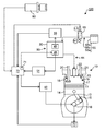
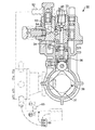
- the conceptual block diagram of the diesel engine concerning one embodiment of this invention The schematic cross section of the fuel injection pump in the engine of FIG. 2 is a schematic cross-sectional view in the axial direction of the camshaft in the fuel injection pump of FIG.
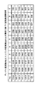
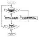
- a map showing the relationship between the dither frequency, the engine speed, and the presence or absence of periodic rotational fluctuations Control flowchart executed by the engine control apparatus of the present embodiment
- An engine includes a fuel injection device having a rack that adjusts an injection amount of fuel injected into a combustion chamber, an actuator that controls a position of the rack, and the fuel based on an indicated rotational speed.
- a control device that controls fuel injection by the injection device and dither-controls the actuator, and the control device provides information on a rotational speed variation region based on a relationship between a dither frequency and the engine speed in the dither control. And the at least one of the dither frequency and the indicated rotational speed is changed when it is determined that the indicated rotational speed is within the rotational speed fluctuation region.
- the rotational speed fluctuation region can be avoided, and the periodic fluctuation of the rotational speed caused by the dither control is suppressed. it can. Also, unpleasant audible sounds that may be caused by periodic fluctuations in the rotational speed can be suppressed.
- the engine according to a second aspect of the present invention is the engine according to the first aspect, wherein the control device rotates with respect to the indicated rotational speed when the controller determines that the indicated rotational speed is within the rotational speed fluctuation region.
- the number is increased or decreased to a corrected rotational speed outside the rotational speed fluctuation range, and fuel injection by the fuel injection device is controlled based on the corrected rotational speed.
- the engine according to a third aspect of the present invention is the engine according to the first aspect, wherein when the control device determines that the indicated rotational speed is within the rotational speed fluctuation region, the indicated rotational speed is set to the rotational speed.
- the dither frequency is changed so as to be outside the fluctuation region, and the actuator is dither controlled based on the changed dither frequency.
- An engine according to a fourth aspect of the present invention is the engine according to any one of the first to third aspects, wherein a rotational speed detection device that detects the rotational speed of the crankshaft, and a position detection device that detects the position of the rack.
- the control device further comprises at least one of information on a rotational speed detected by the rotational speed detection device, a position of the rack detected by the position detection device, and a fuel injection amount by the fuel injection device. Based on one piece of information, information on the rotation speed fluctuation region is created.
- the information on the rotational speed fluctuation region based on the relationship between the dither frequency and the engine speed is learned from the data acquired during operation of the engine, not the information input in advance by the control device. Can be created.
- FIG. 1 is a conceptual configuration diagram of a diesel engine according to an embodiment of the present invention.
- the diesel engine 100 includes an engine body 10, a fuel injection pump 30, a fuel supply unit 55, a starter 60, a shut-off valve 65, a control device 70, and the like. Is provided.
- the fuel injection pump 30 and the shutoff valve 65 constitute a fuel injection device 90.
- the engine main body 10 has a cylinder block 12 and a cylinder head 13, and the cylinder head 13 is disposed at the upper end of the cylinder block 12.
- a plurality of cylinders 11 are provided in the cylinder block 12.
- a piston 14 is fitted in each cylinder 11 so as to be able to reciprocate.
- the piston 14 is connected to the crankshaft 16 via a connecting rod 15.
- a combustion chamber 17 is formed between the upper end of the piston 14 and the lower end of the cylinder head 13.
- the cylinder head 13 has an air supply port 18 and an exhaust port 19.
- This engine includes an intake valve 20 and an exhaust valve 21.
- the intake valve 20 opens and closes the opening of the supply port 18 on the combustion chamber 17 side
- the exhaust valve 21 opens and closes the opening of the exhaust port 19 on the combustion chamber 17 side.
- the cylinder head 13 has a fuel injection nozzle 22. The tip of the fuel injection nozzle 22 protrudes into the combustion chamber 17.
- the fuel injection pump 30 supplies fuel to the fuel injection nozzle 22.
- FIG. 2 is a schematic cross-sectional view of the fuel injection pump 30.
- the fuel injection pump 30 has a hydraulic head 31 and a pump housing 32, and the pump housing 32 is joined to the lower part of the hydraulic head 31.
- a plunger barrel 33 is inserted into the hydraulic head 31 and a plunger 34 is inserted into the plunger barrel 33 so as to be slidable in the vertical direction.
- a plunger lead 34 a is provided on the outer peripheral side surface of the plunger 34.
- the plunger lead 34a is a spiral groove.
- a lower spring receiver 35 slidable in the vertical direction is disposed below the plunger 34 via a spring, and a lower end of the lower spring receiver 35 is rotatably supported by a roller-shaped tappet 36.
- a cam 37 is in contact with the tappet 36.
- the cam 37 is fixed to the camshaft 38, and the camshaft 38 is connected to the crankshaft 16 (see FIG. 1) of the engine body 10 via a gear (not shown).
- the camshaft 38 (cam 37) rotates, and as a result, the plunger 34 performs a stroke operation in the vertical direction.
- FIG. 3 is a schematic cross-sectional view of the fuel injection pump 30 in the axial direction of the cam shaft 38.
- the fuel supply unit 55 supplies fuel to the fuel injection pump 30.
- the plunger barrel 33 has a main port 39, and supplies the fuel pumped from the fuel supply unit 55 to the main port 39.
- the fuel supply unit 55 includes a pump (feed pump) 55a, a fuel tank 55b, and a fuel supply pipe 55c.
- the pump 55a is connected to the cam shaft 38 and is driven in accordance with the rotation of the cam shaft 38 (that is, the stroke operation of the plunger 34).
- the pump 55a is connected to the fuel tank 55b through a fuel supply pipe 55c.
- a pump 55 a is connected to the fuel gallery 54 via a pipe joint 52 and a fuel supply passage 53 provided at the upper part of the fuel injection pump 30, and the fuel gallery 54 is connected to the main port 39.
- the fuel in the fuel tank 55b pumped by driving the pump 55a is supplied to the main port 39 through the fuel supply pipe 55c, the pipe joint 52, the fuel supply passage 53, and the fuel gallery 54.
- the outer peripheral surface of the plunger 34 has a gear (not shown), and the gear meshes with a rack (that is, a fuel metering rack) 45.
- the rack 45 is supported by the pump housing 32 so as to reciprocate.
- the rack 45 is supported so as to be able to reciprocate between one side position and the other side position.
- a rack 45 is connected to a sliding shaft 48 a of an actuator (solenoid) 48 via a control lever 46 and a link lever 47.
- the electronic governor 58 includes a rack 45, an actuator 48, and the like.
- a governor spring 49 is provided between the sliding shaft 48 a of the actuator 48 and the link lever 47.
- the governor spring 49 urges the rack 45 to one side position via the link lever 47. Therefore, in a state where the actuator 48 is not energized, the rack 45 is located at one side position in the movable range, that is, the range between the one side position and the other side position (including the one side position and the other side position). Exists.
- the actuator 48 reciprocates the rack 45 via the link lever 47 and the control lever 46 by reciprocating the sliding shaft 48a. Then, when the rack 45 is reciprocated by the actuator 48, the plunger 34 rotates about its axis. By changing the rotation position of the plunger 34 by the actuator 48, the timing at which the plunger lead 34a communicates with the main port 39 when the plunger 34 is raised is changed. In this way, the fuel injection amount by the fuel injection pump 30 is changed.
- the position detection device 50 is connected to the rack 45, and the position of the rack 45 is detected by the position detection device 50.
- the output value detection device 51 is connected to the actuator 48, and the output value detection device 51 detects the output value of the actuator 48 (the current value flowing through the actuator 48). Further, the rotational speed detection device 73 detects the rotational speed of the crankshaft 16.
- the position detection device 50 outputs a signal representing the position of the rack 45 to the control device 70, and the output value detection device 51 outputs a signal representing the output value of the actuator 48 to the control device 70. Further, the rotational speed detection device 73 outputs a signal representing the rotational speed of the crankshaft 16 to the control device 70.
- the starter 60 has an electric motor and starts the engine.
- the shutoff valve 65 is provided in the fuel supply pipe 55c.
- the shutoff valve 65 is constituted by, for example, an electromagnetic valve, and switches the fuel flow path to the position L1 or the position M1 by sliding the spool to open and close the fuel supply pipe 55c.
- the shutoff valve 65 is composed of an electromagnetic valve, but other members that can open and close the fuel supply pipe may be employed instead of the shutoff valve.
- the control device 70 controls the operation of the actuator 48 and the starter 60.
- a key switch 80 is connected to the control device 70.
- the key switch 80 is an operation tool for starting and stopping the engine.
- the position of the key switch 80 can be changed to any one of an OFF position, an ON position, and a START position.
- the starter 60 and the control device 70 are not energized and are stopped.
- the key switch 80 is operated to the ON position, the actuator 48, the starter 60, and the control device 70 are energized and are in an operable state.
- the control device 70 operates the starter 60 and executes various control programs for starting the engine when the key switch 80 is operated from the ON position to the START position.
- control device 70 includes a memory and a processing circuit corresponding to a processor such as a CPU.
- a processor such as a CPU.
- Various determinations to be described later that are performed in the control device 70 may be configured such that, for example, a processor stores a program stored in a memory so that elements that perform these determinations function.
- the controller 70 may include an integrated circuit that allows these elements to function.
- the control device 70 is connected to the shutoff valve 65 and controls the operation of the shutoff valve 65.
- the control device 70 is connected to the starter 60 and operates the starter 60 to rotate the crankshaft 16 to cause the plunger 34 to perform a stroke operation.
- the control device 70 operates the starter 60 and rotates the crankshaft 16 to start the engine.
- the control device 70 is connected to the position detection device 50 and acquires information on the detection value of the position of the rack 45 from the position detection device 50.
- the control device 70 is connected to the output value detection device 51, and acquires information on the detection value of the output value of the actuator 48 from the output value detection device 51.
- the control device 70 is connected to the actuator 48, and operates the actuator 48 to change the position of the rack 45, thereby changing the rotation position of the plunger 34.
- the control device 70 adjusts the fuel injection amount by the fuel injection pump 30 by changing the rotation position of the plunger 34.
- the control device 70 also includes a signal representing the engine speed from the rotational speed detection device 73, a signal representing the position of the rack 45 from the position detection device 50, and an output value of the actuator 48 from the output value detection device 51.
- the engine speed can be adjusted by controlling the fuel injection pump 30 and the shutoff valve 65 on the basis of at least one of the two signals.
- control device 70 performs dither control, that is, control for exciting the movable part at a specific frequency in order to reduce the friction of the movable part of the actuator 48.
- dither control that is, control for exciting the movable part at a specific frequency in order to reduce the friction of the movable part of the actuator 48.
- the present inventor has found that when such dither control is performed, periodic engine speed fluctuations may occur at a specific engine speed. It has also been found that unpleasant sound (audible sound) that is attached to the ear may be generated due to this periodic fluctuation.
- FIG. 1 a map showing the relationship between the dither frequency and the engine speed and the presence or absence of periodic rotational fluctuations is shown in FIG.
- the leftmost column of the leftmost column indicates the dither frequency [Hz] of dither control
- the numbers in the columns of the other columns indicate the engine speed [min -1 (rpm)].
- the engine speed underlined is the engine speed within a range of ⁇ 20 [min ⁇ 1 ] of the engine speed, and the rotation in which periodic rotational fluctuation caused by dither control occurs. The number (that is, the dangerous rotational speed) is indicated.
- the engine speeds that are not underlined are those in the range of ⁇ 20 [min ⁇ 1 ] of the engine speeds, and periodic rotational fluctuations caused by dither control occur. Indicates the number of rotations that are not.
- the control device 70 has a storage unit 71 (see FIG. 1).
- the storage unit 71 has a map shown in FIG. 4, that is, a map showing the relationship between occurrence of periodic rotational fluctuations based on the relationship (combination) between the dither frequency and the engine speed in the dither control. Stored in advance.
- this map is an example of information on the rotational speed fluctuation region, and the critical rotational speed shown in the map and the rotational speed band of each critical rotational speed ⁇ 20 [min ⁇ 1 ] are as follows: It is a rotation speed fluctuation region.
- control device 70 accesses storage unit 71 to obtain a map (information on the rotational speed fluctuation region), and the indicated rotational speed is determined based on this map. It is determined whether the rotation speed is within the range.
- the rotational fluctuation region is an engine rotational speed region (for example, a critical rotational speed range of ⁇ 20 [min ⁇ 1 ]) that causes periodic rotational fluctuation due to dither control.
- the fluctuation region is determined for each dither frequency.
- the instruction rotational speed is a command value for the rotational speed of the engine 100 that is input to the control device 70 when the operator operates the accelerator in the engine 100. It may be a case where the control device 70 calculates the indicated rotational speed based on the accelerator opening signal.
- step S1 if the control device 70 determines that the indicated rotational speed is not the rotational speed within the rotational fluctuation region, the process proceeds to step S2.
- step S ⁇ b> 2 the control device 70 performs fuel injection control for the first predetermined time with the designated rotational speed as the rotational speed.
- the fuel injection control is performed by adjusting the engine speed. Specifically, the control device 70 outputs a signal indicating the engine speed from the rotation speed detection device 73, a signal indicating the position of the rack 45 from the position detection device 50, and the output value detection device 51 to the actuator 48.
- the fuel injection control is performed by controlling the fuel injection pump 30 and the shutoff valve 65 based on the signal representing the output value. Thereafter, the process proceeds to step S3.
- step S3 the control device 70 determines whether an engine stop signal has been received, in other words, whether the key switch 80 has been operated to the OFF position. If the control device 70 determines in step S3 that it has received an engine stop signal, the control is ended. On the other hand, if control device 70 determines that it has not received the engine stop signal, it returns to step S1.
- step S1 when the control device 70 determines in step S1 that the indicated rotational speed is the rotational speed within the rotational fluctuation region, the process proceeds to step S4.
- step S4 the control device 70 changes the command rotational speed to a rotational speed outside the rotational fluctuation region, and performs fuel injection control. Specifically, fuel injection control for a second predetermined time corresponding to the corrected rotational speed is performed using the rotational speed obtained by adding the predetermined rotational speed ⁇ to the indicated rotational speed within the rotational speed fluctuation region as the corrected rotational speed.
- the predetermined rotational speed ⁇ may be any positive rotational speed, but the indicated rotational speed within the rotational speed band of the dangerous rotational speed ⁇ 20 [min ⁇ 1 ] is out of the band by adding the predetermined rotational speed ⁇ . It is desirable to adopt a numerical value such that From this point of view, in the example of the present embodiment, for example, a value of about 20 [min ⁇ 1 ] is adopted as the predetermined rotation speed ⁇ .
- the control device 70 includes a signal indicating the engine speed from the rotation speed detection device 73, a signal indicating the position of the rack 45 from the position detection device 50, and a signal from the output value detection device 51 to the actuator 48. Based on the signal indicating the output value, the fuel injection pump 30 and the shutoff valve 65 are controlled to adjust the engine speed. Thereafter, the process proceeds to step S3.
- the second predetermined time may be the same time as the first predetermined time or a different time. However, when the fuel pressure is the same and the number of revolutions of the engine 100 is increased by performing fuel injection control for the second predetermined time, the second predetermined time is longer than the first predetermined time. It becomes.
- the control device 70 changes the engine speed (instructed engine speed) so as to avoid the engine speed fluctuation region in which the engine speed periodically fluctuates due to dither control. Therefore, it is possible to suppress occurrence of periodic fluctuations in the rotation speed while performing dither control. Therefore, unpleasant audible sounds can be suppressed.
- control device 70 avoids the rotation speed fluctuation region by controlling the fuel injection device 90, it is possible to suppress unpleasant audible sounds with a simple configuration.
- the control device 70 determines that the designated rotational speed is within the rotational speed fluctuation region, the control device 70 sets the rotational speed obtained by adding the predetermined rotational speed ⁇ to the designated rotational speed. The fuel injection control was performed at this corrected rotational speed.
- the control device determines that the commanded rotational speed is within the rotational speed fluctuation region, the control device sets the rotational speed obtained by subtracting the predetermined rotational speed ⁇ from the commanded rotational speed as the corrected rotational speed, The fuel injection control may be performed at this corrected rotational speed.
- the predetermined rotational speed ⁇ may be the same value as or different from the predetermined rotational speed ⁇ , but the indicated rotational speed within the rotational speed band of the critical rotational speed ⁇ 20 [min ⁇ 1 ] is the predetermined rotational speed ⁇ . It is desirable to adopt a numerical value that results in an out-of-band speed by subtracting.
- control device 70 determines that the commanded rotational speed is within the rotational speed fluctuation region, the control device 70 performs control to change only the dither frequency of the actuator 48, whereby the dither frequency, the engine rotational speed, and the like. These sets may be outside the rotation speed fluctuation region. Further, the control device 70 may change both the indicated rotational speed and the dither frequency so that the set of the dither frequency and the engine rotational speed is outside the rotational speed fluctuation region.
- the determination as to whether or not the set of the dither frequency and the engine speed is within the engine speed fluctuation region is limited to the case where the determination is made based on the map shown in FIG. Absent. Instead of such a case, for example, during the operation of the engine, the state and conditions of periodic rotational fluctuations that actually occurred are detected, and the control device learns to recognize the dangerous rotational speed and rotate it. A number variation area may be created, and the determination may be made based on the created rotation speed fluctuation area.
- the control device may create the rotation speed fluctuation region based on at least one of these pieces of information, that is, information on the rotation speed, the rack position, and the fuel injection amount.
- the engine of the present invention may be a diesel engine of any specification regardless of the number of cylinders.
- the engine of the present invention may be an engine other than a diesel engine.
- the engine of the present invention may be any engine that performs dither control of an actuator that controls the position of the rack.
Abstract
エンジンが、燃焼室へ噴射する燃料の噴射量を調整するラックと、ラックの位置を制御するアクチュエータとを有する燃料噴射装置と、指示回転数に基づいて燃料噴射装置による燃料噴射を制御するとともに、アクチュエータをディザー制御する制御装置と、を備え、制御装置は、ディザー制御におけるディザー周波数とエンジンの回転数との関係に基づく回転数変動領域の情報を有し、指示回転数が回転数変動領域内にあると判断した場合に、ディザー周波数および指示回転数の少なくとも一方を変更する。これにより、ディザー制御により引き起こされる周期的なエンジン速度の変動を抑制できるエンジンを提供する。
Description
本発明は、エンジンに関する。
従来、エンジンとしては、例えば、特許文献1に記載されたディーゼルエンジンがある。特許文献1のディーゼルエンジンは、制御装置と、電子ガバナとを備え、電子ガバナは、電動アクチュエータと燃料調量ラックとを有する。制御装置は、電動アクチュエータの出力部が往復作動するように電動アクチュエータを制御する。電動アクチュエータの出力部が往復作動することによって、燃料調量ラックを所定のストロークで往復摺動させるようになっている。このディーゼルエンジンでは、このように燃料調量ラックの位置を調整することにより、燃焼室に噴射する燃料の量を調整している。
また、特許文献1のディーゼルエンジンでは、電動アクチュエータにより燃料調量ラックを微小振動させるディザー制御が行われている。ディザー制御を行うことで、電動アクチュエータおよび燃料調量ラックにおける可動部の静摩擦を動摩擦として摩擦力を低減でき、応答性を高めた制御を実現できる。
本発明者は、電子ガバナを備えるエンジンに次の問題が生じる場合があることを見出した。具体的には、アクチュエータに対して特定周波数で励起させるディザー制御を行った場合、特定のエンジン速度(すなわち、回転数)において周期的なエンジン速度の変動が引き起こる場合があることを見出した。そして、この周期的な変動が生じた場合に、特定周波数で耳に付く不快な音(可聴音)が生じる場合があることを見出した。
本発明の目的は、ディザー制御により引き起こされる周期的なエンジン速度の変動を抑制できるエンジンを提供することにある。
上記目的を達成するために、本発明のエンジンは以下のように構成する。
本発明の一の態様にかかるエンジンは、燃焼室へ噴射する燃料の噴射量を調整するラックと、前記ラックの位置を制御するアクチュエータとを有する燃料噴射装置と、指示回転数に基づいて前記燃料噴射装置による燃料噴射を制御するとともに、前記アクチュエータをディザー制御する制御装置と、を備え、前記制御装置は、前記ディザー制御におけるディザー周波数とエンジンの回転数との関係に基づく回転数変動領域の情報を有し、前記指示回転数が前記回転数変動領域内にあると判断した場合に、前記ディザー周波数および前記指示回転数の少なくとも一方を変更する、ものである。
本発明のエンジンによれば、ディザー制御により引き起こされる周期的なエンジン速度の変動を抑制することができる。
本発明の第1態様にかかるエンジンは、燃焼室へ噴射する燃料の噴射量を調整するラックと、前記ラックの位置を制御するアクチュエータとを有する燃料噴射装置と、指示回転数に基づいて前記燃料噴射装置による燃料噴射を制御するとともに、前記アクチュエータをディザー制御する制御装置と、を備え、前記制御装置は、前記ディザー制御におけるディザー周波数とエンジンの回転数との関係に基づく回転数変動領域の情報を有し、前記指示回転数が前記回転数変動領域内にあると判断した場合に、前記ディザー周波数および前記指示回転数の少なくとも一方を変更する、ものである。
このような構成によれば、ディザー周波数および指示回転数の少なくともいずれか一方を変更することで、回転数変動領域を回避することができ、ディザー制御により引き起こされる回転数の周期的な変動を抑制できる。また、回転数の周期的な変動により生じる場合がある不快な可聴音を抑制できる。
本発明の第2態様にかかるエンジンは、第1態様のエンジンにおいて、前記制御装置は、前記指示回転数が前記回転数変動領域内にあると判断した場合に、前記指示回転数に対して回転数を増減して、前記回転数変動領域外にある補正回転数とし、前記補正回転数に基づいて、前記燃料噴射装置による燃料噴射を制御する、ものである。
本発明の第3態様にかかるエンジンは、第1態様のエンジンにおいて、前記制御装置は、前記指示回転数が前記回転数変動領域内にあると判断した場合に、前記指示回転数を前記回転数変動領域外とするように前記ディザー周波数を変更し、前記変更されたディザー周波数に基づいて、前記アクチュエータをディザー制御する、ものである。
本発明の第4態様にかかるエンジンは、第1から第3のいずれかの態様のエンジンにおいて、クランク軸の回転数を検出する回転数検出装置と、前記ラックの位置を検出する位置検出装置と、をさらに備え、前記制御装置は、前記回転数検出装置により検出された回転数、前記位置検出装置により検出された前記ラックの位置、および前記燃料噴射装置による燃料噴射量の情報のうちの少なくとも1つの情報に基づいて、前記回転数変動領域の情報を作成する、ものである。
このような構成によれば、ディザー周波数とエンジンの回転数との関係に基づく回転数変動領域の情報を、制御装置が予めインプットされた情報ではなく、エンジンの運転中に取得したデータから学習して作成することができる。
(実施の形態)
以下に、本開示にかかる実施の形態を図面に基づいて詳細に説明する。
以下に、本開示にかかる実施の形態を図面に基づいて詳細に説明する。
図1は、本発明の一の実施の形態にかかるディーゼルエンジンの概念構成図である。
図1に示すように、このディーゼルエンジン(以下、単にエンジンという)100は、エンジン本体10と、燃料噴射ポンプ30と、燃料供給部55と、スタータ60と、遮断弁65と、制御装置70とを備える。本実施の形態では、燃料噴射ポンプ30と、遮断弁65とは、燃料噴射装置90を構成する。
エンジン本体10は、シリンダブロック12と、シリンダヘッド13とを有し、シリンダヘッド13は、シリンダブロック12の上端に配置されている。シリンダブロック12には、複数の気筒11が設けられている。各気筒11内には、ピストン14が往復動可能に嵌挿されている。ピストン14は、コンロッド15を介してクランク軸16に連結している。ピストン14の上端と、シリンダヘッド13の下端との間に、燃焼室17を形成している。シリンダヘッド13は、給気ポート18と、排気ポート19とを有する。
このエンジンは、吸気弁20と、排気弁21とを備える。吸気弁20は、給気ポート18の燃焼室17側の開口を開閉し、排気弁21は、排気ポート19の燃焼室17側の開口を開閉する。シリンダヘッド13は、燃料噴射ノズル22を有する。燃料噴射ノズル22の先端部は、燃焼室17内に突出している。また、燃料噴射ポンプ30は、燃料噴射ノズル22へ燃料を供給する。
図2は、燃料噴射ポンプ30の模式断面図である。
燃料噴射ポンプ30は、ハイドロリックヘッド31と、ポンプハウジング32とを有し、ポンプハウジング32は、ハイドロリックヘッド31の下部に接合されている。ハイドロリックヘッド31にはプランジャバレル33が挿入配置され、プランジャバレル33内にはプランジャ34が上下方向に摺動自在に挿入配置されている。プランジャ34の外周側面にはプランジャリード34aが設けられている。プランジャリード34aは螺旋状の溝である。上下方向に摺動自在の下部バネ受け35を、プランジャ34の下方にバネを介して配置し、ローラ状のタペット36で下部バネ受け35の下端部を回転可能に軸支する。タペット36にはカム37が当接している。カム37はカム軸38に固定され、図示しない歯車を介してエンジン本体10のクランク軸16(図1参照)にカム軸38が接続されている。クランク軸16が回転することによって、カム軸38(カム37)が回転し、その結果、プランジャ34が上下方向にストローク動作する。
図3は、カム軸38の軸方向における燃料噴射ポンプ30の模式断面図である。
燃料供給部55は燃料噴射ポンプ30に燃料を供給する。図3に示すように、プランジャバレル33は、メインポート39を有し、燃料供給部55から圧送した燃料をメインポート39に供給する。
燃料供給部55は、ポンプ(フィードポンプ)55aと、燃料タンク55bと、燃料供給管55cとを有する。ポンプ55aは、カム軸38に接続され、カム軸38の回転(すなわち、プランジャ34のストローク動作)に伴って駆動する。ポンプ55aは、燃料供給管55cを介して燃料タンク55bに接続されている。燃料噴射ポンプ30の上部に設けられる管継手52と燃料供給通路53とを介して燃料ギャラリ54にポンプ55aが、接続され、燃料ギャラリ54がメインポート39に接続されている。ポンプ55aを駆動することによって圧送した燃料タンク55b内の燃料が、燃料供給管55c、管継手52、燃料供給通路53および燃料ギャラリ54を介してメインポート39に供給される。
図2および図3を参照して、プランジャ34が上下方向の可動範囲内における最下位置(下死点)に移動したとき、プランジャバレル33内の燃料圧室40とメインポート39とが連通し、燃料が燃料圧室40に導入される。一方、プランジャ34がカム37により押し上げられて上昇すると、プランジャ34の外壁がメインポート39の燃料圧室40への連通口を閉ざす。その結果、燃料圧室40内の燃料がプランジャ34の上昇に伴って圧縮されるとともに、分配ポート41を介して分配軸42に送られる。そして、圧送された燃料が分配軸42によってデリベリバルブ43へ分配された後、噴射管44を通ってエンジン本体10の燃料噴射ノズル22から噴射されて、燃焼室17(図1参照)内へ供給される。
また、図2および図3を参照して、プランジャ34が更に上昇すると、プランジャ34に形成されたプランジャリード34aとメインポート39とが連通するとともに、プランジャバレル33内とメインポート39とが連通する。そうすると、プランジャバレル33内の燃料がメインポート39の燃料供給部55側へ逆流し、燃料噴射ポンプ30による燃料の噴射が停止される。
図2を参照して、プランジャ34の外周面は、歯車(図示せず)を有し、その歯車は、ラック(すなわち、燃料調量ラック)45と噛合している。ラック45は、ポンプハウジング32により往復動可能に支持されている。ラック45は、一方側位置と他方側位置との間で往復動可能に支持されている。コントロールレバー46およびリンクレバー47を介してアクチュエータ(ソレノイド)48の摺動軸48aにラック45が接続されている。燃料噴射ポンプ30において、電子ガバナ58は、ラック45およびアクチュエータ48等により構成されている。
アクチュエータ48の摺動軸48aとリンクレバー47との間に、ガバナスプリング49が設けられている。ガバナスプリング49は、リンクレバー47を介してラック45を一方側位置へ付勢している。したがって、アクチュエータ48が通電されていない状態では、ラック45は、可動範囲、すなわち、一方側位置と他方側位置との間(一方側位置と他方側位置とを含む)の範囲における一方側位置に存在する。
摺動軸48aを往復動させることによって、アクチュエータ48は、リンクレバー47およびコントロールレバー46を介してラック45を往復動させる。そして、アクチュエータ48によりラック45が往復動されることによって、プランジャ34がその軸回りに回動する。アクチュエータ48によりプランジャ34の回動位置を変更することによって、プランジャ34の上昇時における、プランジャリード34aとメインポート39との連通するタイミングを変更する。このようにして、燃料噴射ポンプ30による燃料噴射量を変更する。
図1に示すように、位置検出装置50をラック45に接続し、位置検出装置50によりラック45の位置を検出する。また、出力値検出装置51をアクチュエータ48に接続し、出力値検出装置51によりアクチュエータ48の出力値(アクチュエータ48に流れる電流値)を検出する。また、回転数検出装置73は、クランク軸16の回転数を検出する。
位置検出装置50は、ラック45の位置を表す信号を制御装置70に出力し、出力値検出装置51は、アクチュエータ48の出力値を表す信号を制御装置70に出力する。また、回転数検出装置73は、クランク軸16の回転数を表す信号を制御装置70に出力する。
スタータ60は、電動モータを有し、エンジンを始動させる。また、遮断弁65は燃料供給管55cに設けられている。遮断弁65は、例えば、電磁弁で構成され、スプールを摺動させて燃料供給管55cを開閉することにより、燃料の流路を位置L1または位置M1に切り換える。
遮断弁65のスプールが、位置L1の状態(閉状態)にある場合には、燃料供給管55cが遮断され、燃料供給部55から燃料噴射ポンプ30に燃料が供給されない。その結果、燃料が燃料噴射ポンプ30から噴出不能な状態になり、燃料が燃料噴射ポンプ30から燃焼室17内へ供給不能な状態になる。
一方、遮断弁65のスプールが、位置M1の状態(開状態)にある場合には、燃料供給管55cが開放され、燃料供給部55から燃料噴射ポンプ30に燃料が供給される。その結果、燃料が燃料噴射ポンプ30から噴出可能な状態になり、燃料が燃料噴射ポンプ30から燃焼室17内へ供給可能な状態になる。なお、本実施の形態では遮断弁65を電磁弁で構成したが、遮断弁の代わりに燃料供給管を開閉可能な他の部材を採用してもよい。
制御装置70は、アクチュエータ48およびスタータ60の動作を制御する。図1に示すように、制御装置70にキースイッチ80を接続している。キースイッチ80は、エンジンの始動および停止を行うための操作具である。キースイッチ80の位置は、OFF位置、ON位置およびSTART位置のいずれかに変更可能である。キースイッチ80が前記OFF位置に操作されているときには、スタータ60および制御装置70が通電されておらず、停止している。キースイッチ80が前記ON位置に操作されているときには、アクチュエータ48、スタータ60および制御装置70が通電されており、作動可能な状態となっている。制御装置70は、キースイッチ80が前記ON位置から前記START位置に操作されたときに、スタータ60を作動させるとともに、エンジンを始動させるための各種制御プログラムを実行する。
また、制御装置70は、メモリと、CPUなどのプロセッサに対応する処理回路とを備える。制御装置70において行われる後述する各種判断は、例えば、メモリに記憶されたプログラムをプロセッサが実行することにより、これらの判断を行う要素を機能させるようししてもよい。あるいは、これらの要素を機能させる集積回路を制御装置70が備えてもよい。
制御装置70は、遮断弁65に接続されており、遮断弁65の動作を制御する。制御装置70は、スタータ60に接続されており、スタータ60を操作して、クランク軸16を回転させることによって、プランジャ34にストローク動作を行わせる。制御装置70は、スタータ60を操作して、クランク軸16を回転させることによって、エンジンを始動させる。
制御装置70は、位置検出装置50に接続され、位置検出装置50からラック45の位置の検出値の情報を取得する。また、制御装置70は、出力値検出装置51に接続され、出力値検出装置51からアクチュエータ48の出力値の検出値の情報を取得する。
制御装置70は、アクチュエータ48に接続されており、アクチュエータ48を操作して、ラック45の位置を変更することで、プランジャ34の回動位置を変更する。制御装置70は、プランジャ34の回動位置を変更することで、燃料噴射ポンプ30による燃料噴射量を調整する。また、制御装置70は、回転数検出装置73からのエンジンの回転数を表す信号と、位置検出装置50からのラック45の位置を表す信号と、出力値検出装置51からのアクチュエータ48の出力値を表す信号とのうちの少なくとも一つの信号に基づいて、燃料噴射ポンプ30および遮断弁65を制御することによって、エンジンの回転数の調整を行うことが可能になっている。
また、制御装置70は、アクチュエータ48の可動部の摩擦を低減するため、ディザー制御、すなわち、可動部を特定周波数で励起させる制御を行っている。このディザー制御で、アクチュエータ48の滑らかな摺動を実現して、燃料噴射の制御性を向上している。
本発明者は、このようなディザー制御を行った場合、特定のエンジンの速度において周期的なエンジン速度の変動が引き起こる場合があることを見出した。また、この周期的な変動により、耳に付く不快な音(可聴音)が生じる場合があることを見出した。
ここで、ディザー周波数およびエンジンの回転数と、周期的な回転変動の発生の有無との関係を示すマップを図4に示す。
図4において、最も左に示す左端の列のコラムは、ディザー制御のディザー周波数[Hz]を示し、それ以外の列(上端の行は除く)のコラム内の数字は、エンジンの回転数[min-1(rpm)]を示す。また、エンジンの回転数のうちで下線が引かれた回転数は、その回転数の±20[min-1]の範囲の回転数で、ディザー制御に起因する周期的な回転変動が発生した回転数(すなわち、危険回転数)を示す。一方、エンジンの回転数のうちで下線が引かれていない回転数は、その回転数の±20[min-1]の範囲の回転数で、ディザー制御に起因する周期的な回転変動が発生していない回転数を示す。
図4において、例えば、ディザー周波数が178.6[Hz]の場合、10716±20[min-1]、5358±20[min-1]、3572±20[min-1]および2679±20[min-1]の回転数の範囲では、ディザー制御に起因する周期的な回転変動が発生しなかったことを示す。また、図4において、例えば、ディザー周波数が178.6[Hz]の場合、2143±20[min-1]、1786±20[min-1]、1531±20[min-1]、1340±20[min-1]および1191±20[min-1]の回転数の範囲で、ディザー制御に起因する周期的な回転変動が発生したことを示す。
制御装置70は記憶部71(図1参照)を有する。この記憶部71には、図4に示すマップ、すなわち、ディザー制御におけるディザー周波数とエンジンの回転数との関係(組み合わせ)に基づく、周期的な回転変動の発生の有無との関係を示すマップが予め記憶されている。本実施の形態では、このマップが回転数変動領域の情報の一例となっており、マップに示されている危険回転数とそれぞれの危険回転数±20[min-1]の回転数帯域が、回転数変動領域となっている。
次に、制御装置70で実行される制御のフローチャートを図5に示す。
キースイッチ80を前記ON位置から前記START位置に操作することによって、エンジン100を始動させて、制御をスタートさせる。エンジン100が始動すると、ステップS1にて、制御装置70が記憶部71にアクセスすることによって、マップ(回転数変動領域の情報)を取得し、このマップに基づいて指示回転数が回転数変動領域内の回転数か否かを判断する。なお、回転変動領域とは、ディザー制御に起因して周期的な回転変動を起こすエンジンの回転数領域(例えば、危険回転数±20[min-1]の回転数帯域)のことであり、回転変動領域はディザー周波数毎に決定される。また、指示回転数とは、エンジン100において、オペレータがアクセルを操作する等して、制御装置70に対して入力されるエンジン100の回転数の指令値である。アクセルの開度信号に基づいて、制御装置70が指示回転数を算定するような場合であってもよい。
ステップS1にて、制御装置70が、指示回転数が回転変動領域内の回転数でないと判断するとステップS2に移行する。ステップS2で、制御装置70が、指示回転数を回転数として、第1所定時間の燃料噴射制御を行う。燃料噴射制御は、エンジンの回転数の調整を行うことによって行われる。具体的には、制御装置70が、回転数検出装置73からのエンジンの回転数を表す信号と、位置検出装置50からのラック45の位置を表す信号と、出力値検出装置51からアクチュエータ48の出力値を表す信号とに基づいて、燃料噴射ポンプ30および遮断弁65を制御することにより、燃料噴射制御が行われる。その後、ステップS3に移行する。
ステップS3では、制御装置70が、エンジン停止信号を受けたか、言い換えると、キースイッチ80がOFF位置に操作されたか否かを判断する。ステップS3で、制御装置70が、エンジン停止信号を受けたと判断すると、制御がエンドになる。一方、制御装置70が、エンジン停止信号を受けなかったと判断すると、ステップS1に戻る。
一方、ステップS1で、制御装置70が、指示回転数が回転変動領域内での回転数であると判断するとステップS4に移行する。そして、ステップS4で、制御装置70が、指示回転数を、回転変動領域外の回転数に変更して燃料噴射制御を行う。具体的には、回転数変動領域内にある指示回転数に、所定回転数αを加算した回転数を補正回転数として、この補正回転数に対応した第2所定時間の燃料噴射制御を行う。また、所定回転数αは、如何なる正の回転数でもよいが、危険回転数±20[min-1]の回転数帯域内に入っている指示回転数が、所定回転数αの加算により帯域外の回転数となるような数値を採用することが望ましい。このような観点から、本実施の形態の例では、所定回転数αは、例えば、20[min-1]程度の値が採用される。
燃料噴射制御は、制御装置70が、回転数検出装置73からのエンジンの回転数を表す信号と、位置検出装置50からのラック45の位置を表す信号と、出力値検出装置51からアクチュエータ48の出力値を表す信号とに基づいて、燃料噴射ポンプ30および遮断弁65を制御し、エンジンの回転数の調整を行うことによって行う。その後、ステップS3に移行する。なお、第2所定時間は、第1所定時間と同じ時間でもよく、異なる時間でもよい。ただし、燃料の圧力が同じ場合にあって、第2所定時間の燃料噴射制御を行うことで、エンジン100の回転数を増加させる場合には、第2所定時間は第1所定時間よりも長い時間となる。
本実施の形態によれば、制御装置70は、ディザー制御に起因して回転数の周期的な変動が生じる回転数変動領域を避けるように、エンジンの回転数(指示回転数)を変更する。よって、ディザー制御を実施しながら、回転数の周期的な変動が生じることが抑制できる。したがって、不快な可聴音を抑制できる。
また、制御装置70は、燃料噴射装置90を制御することにより回転数変動領域を回避しているため、簡便な構成で、不快な可聴音を抑制できる。
なお、上述の実施の形態の説明では、制御装置70が、指示回転数が回転数変動領域内にあると判断すると、制御装置70が、指示回転数に所定回転数αを加算した回転数を補正回転数とし、この補正回転数にて燃料噴射制御を行っていた。このような場合に代えて、制御装置が、指示回転数が回転数変動領域内にあると判断すると、制御装置が、指示回転数に所定回転数βを減算した回転数を補正回転数とし、この補正回転数にて燃料噴射制御を行ってもよい。なお、所定回転数βは、所定回転数αと同じ値でも異なる値でもよいが、危険回転数±20[min-1]の回転数帯域内に入っている指示回転数が、所定回転数βの減算により帯域外の回転数となるような数値を採用することが望ましい。
また、制御装置70が、指示回転数が回転数変動領域内にあると判断すると、制御装置70が、アクチュエータ48のディザー周波数のみを変更する制御を行うことにより、ディザー周波数とエンジンの回転数との組を、回転数変動領域外とするようにしてもよい。また、制御装置70が、指示回転数とディザー周波数との両方を変更することで、ディザー周波数とエンジンの回転数との組を、回転数変動領域外とするようにしてもよい。
また、ディザー周波数とエンジンの回転数との組が回転数変動領域内にあるか否かの判断は、予め記憶部71に記憶した図4に示すマップに基づいて判断するような場合に限られない。このような場合に代えて、例えば、エンジンの運転中に、実際に起こった周期的な回転変動の状態・条件を検出して、制御装置が学習することにより、危険回転数を認定して回転数変動領域を作成し、作成された回転数変動領域に基づいて判断を行うようにしてもよい。
制御装置は、例えば、回転数の変動幅(最大値から最小値をひいた値)が予め定められた値より大きく、かつ回転の変動に周期がある場合、ラック位置の変動幅(ラック位置が変動する場合のラックの存在する範囲)が予め定められた値より大きく、かつラック位置の変動に周期がある場合、および、燃料噴射量の変動幅(噴射量が変動する場合の一秒あたりの噴射量の最大値から一秒あたりの噴射量の最小値をひいた値)が予め定められた値より大きく、かつ噴射量の変動に周期がある場合、のうちの少なくとも1つを満足する場合に、ディザー制御に起因する周期的な回転変動が発生していると判断してもよい。制御装置は、これらの情報、すなわち、回転数、ラック位置、および燃料噴射量の情報のうちの少なくとも1つの情報に基づいて、回転数変動領域を作成してもよい。
なお、本発明のエンジンは、気筒数等によらず、如何なる仕様のディーゼルエンジンであってもよい。また、本発明のエンジンは、ディーゼルエンジン以外のエンジンであってもよい。本発明のエンジンは、ラックの位置を制御するアクチュエータのディザー制御を行うエンジンであれば如何なるエンジンであってもよい。
なお、上記様々な実施の形態のうちの任意の実施の形態を適宜組み合わせることにより、それぞれの有する効果を奏するようにすることができる。
本発明は、添付図面を参照しながら好ましい実施の形態に関連して充分に記載されているが、この技術の熟練した人々にとっては種々の変形や修正は明白である。そのような変形や修正は、添付した請求の範囲による本発明の範囲から外れない限りにおいて、その中に含まれると理解されるべきである。
16 クランク軸
17 燃焼室
30 燃料噴射ポンプ
45 ラック
48 アクチュエータ
50 位置検出装置
58 電子ガバナ
65 遮断弁
70 制御装置
71 記憶部
73 回転数検出装置
80 キースイッチ
90 燃料噴射装置
100 エンジン
17 燃焼室
30 燃料噴射ポンプ
45 ラック
48 アクチュエータ
50 位置検出装置
58 電子ガバナ
65 遮断弁
70 制御装置
71 記憶部
73 回転数検出装置
80 キースイッチ
90 燃料噴射装置
100 エンジン
Claims (4)
- 燃焼室へ噴射する燃料の噴射量を調整するラックと、前記ラックの位置を制御するアクチュエータとを有する燃料噴射装置と、
指示回転数に基づいて前記燃料噴射装置による燃料噴射を制御するとともに、前記アクチュエータをディザー制御する制御装置と、を備え、
前記制御装置は、前記ディザー制御におけるディザー周波数とエンジンの回転数との関係に基づく回転数変動領域の情報を有し、前記指示回転数が前記回転数変動領域内にあると判断した場合に、前記ディザー周波数および前記指示回転数の少なくとも一方を変更する、エンジン。 - 前記制御装置は、前記指示回転数が前記回転数変動領域内にあると判断した場合に、前記指示回転数に対して回転数を増減して、前記回転数変動領域外にある補正回転数とし、前記補正回転数に基づいて、前記燃料噴射装置による燃料噴射を制御する、請求項1に記載のエンジン。
- 前記制御装置は、前記指示回転数が前記回転数変動領域内にあると判断した場合に、前記指示回転数を前記回転数変動領域外とするように前記ディザー周波数を変更し、前記変更されたディザー周波数に基づいて、前記アクチュエータをディザー制御する、請求項1に記載のエンジン。
- クランク軸の回転数を検出する回転数検出装置と、
前記ラックの位置を検出する位置検出装置と、をさらに備え、
前記制御装置は、前記回転数検出装置により検出された回転数、前記位置検出装置により検出された前記ラックの位置、および前記燃料噴射装置による燃料噴射量の情報のうちの少なくとも1つの情報に基づいて、前記回転数変動領域の情報を作成する、請求項1から3のいずれか1つに記載のエンジン。
Priority Applications (3)
| Application Number | Priority Date | Filing Date | Title |
|---|---|---|---|
| EP16853627.4A EP3361076B1 (en) | 2015-10-07 | 2016-10-05 | Engine |
| CN201680053172.2A CN108138680B (zh) | 2015-10-07 | 2016-10-05 | 发动机 |
| US15/765,550 US10655544B2 (en) | 2015-10-07 | 2016-10-05 | Engine |
Applications Claiming Priority (2)
| Application Number | Priority Date | Filing Date | Title |
|---|---|---|---|
| JP2015-199454 | 2015-10-07 | ||
| JP2015199454A JP6464070B2 (ja) | 2015-10-07 | 2015-10-07 | エンジン |
Publications (1)
| Publication Number | Publication Date |
|---|---|
| WO2017061473A1 true WO2017061473A1 (ja) | 2017-04-13 |
Family
ID=58487750
Family Applications (1)
| Application Number | Title | Priority Date | Filing Date |
|---|---|---|---|
| PCT/JP2016/079633 WO2017061473A1 (ja) | 2015-10-07 | 2016-10-05 | エンジン |
Country Status (5)
| Country | Link |
|---|---|
| US (1) | US10655544B2 (ja) |
| EP (1) | EP3361076B1 (ja) |
| JP (1) | JP6464070B2 (ja) |
| CN (1) | CN108138680B (ja) |
| WO (1) | WO2017061473A1 (ja) |
Families Citing this family (1)
| Publication number | Priority date | Publication date | Assignee | Title |
|---|---|---|---|---|
| JP6965614B2 (ja) * | 2017-07-21 | 2021-11-10 | トヨタ自動車株式会社 | 内燃機関の制御装置 |
Citations (2)
| Publication number | Priority date | Publication date | Assignee | Title |
|---|---|---|---|---|
| JP2006207376A (ja) * | 2005-01-25 | 2006-08-10 | Kubota Corp | 電子ガバナ |
| JP2009085063A (ja) * | 2007-09-28 | 2009-04-23 | Kubota Corp | エンジンの電子ガバナ |
Family Cites Families (12)
| Publication number | Priority date | Publication date | Assignee | Title |
|---|---|---|---|---|
| US4493302A (en) * | 1982-02-01 | 1985-01-15 | Nissan Motor Company, Limited | Fuel injection timing control system for an internal combustion engine |
| JP3744036B2 (ja) * | 1995-10-31 | 2006-02-08 | 日産自動車株式会社 | ディーゼルエンジンの燃料性状検出装置および制御装置 |
| JP3572433B2 (ja) * | 1997-01-31 | 2004-10-06 | 日産自動車株式会社 | ディーゼルエンジン用燃料噴射ポンプの燃料噴射時期制御装置 |
| JP2004190628A (ja) * | 2002-12-13 | 2004-07-08 | Isuzu Motors Ltd | コモンレール式燃料噴射制御装置 |
| JP2006077581A (ja) * | 2004-09-07 | 2006-03-23 | Kubota Corp | 電子ガバナ |
| JP2006077580A (ja) * | 2004-09-07 | 2006-03-23 | Kubota Corp | 電子ガバナ |
| JP2007040361A (ja) * | 2005-08-02 | 2007-02-15 | Bosch Corp | 電磁弁駆動制御方法 |
| JP5092604B2 (ja) * | 2006-10-30 | 2012-12-05 | 日産自動車株式会社 | 振動低減装置 |
| JP2008215145A (ja) * | 2007-03-01 | 2008-09-18 | Yanmar Co Ltd | 電子制御ガバナ |
| US8176895B2 (en) * | 2007-03-01 | 2012-05-15 | Yanmar Co., Ltd. | Electronic control governor |
| JP2009085062A (ja) * | 2007-09-28 | 2009-04-23 | Kubota Corp | エンジンの電子ガバナ |
| JP5865219B2 (ja) | 2012-09-24 | 2016-02-17 | 株式会社クボタ | 電子ガバナ付きディーゼルエンジン |
-
2015
- 2015-10-07 JP JP2015199454A patent/JP6464070B2/ja active Active
-
2016
- 2016-10-05 WO PCT/JP2016/079633 patent/WO2017061473A1/ja active Application Filing
- 2016-10-05 EP EP16853627.4A patent/EP3361076B1/en active Active
- 2016-10-05 US US15/765,550 patent/US10655544B2/en active Active
- 2016-10-05 CN CN201680053172.2A patent/CN108138680B/zh not_active Expired - Fee Related
Patent Citations (2)
| Publication number | Priority date | Publication date | Assignee | Title |
|---|---|---|---|---|
| JP2006207376A (ja) * | 2005-01-25 | 2006-08-10 | Kubota Corp | 電子ガバナ |
| JP2009085063A (ja) * | 2007-09-28 | 2009-04-23 | Kubota Corp | エンジンの電子ガバナ |
Also Published As
| Publication number | Publication date |
|---|---|
| EP3361076A4 (en) | 2019-06-19 |
| US20180291821A1 (en) | 2018-10-11 |
| CN108138680A (zh) | 2018-06-08 |
| US10655544B2 (en) | 2020-05-19 |
| JP2017072075A (ja) | 2017-04-13 |
| EP3361076A1 (en) | 2018-08-15 |
| CN108138680B (zh) | 2021-05-11 |
| EP3361076B1 (en) | 2020-12-02 |
| JP6464070B2 (ja) | 2019-02-06 |
Similar Documents
| Publication | Publication Date | Title |
|---|---|---|
| US10760521B2 (en) | Control device and control method for fuel pump | |
| JP4535024B2 (ja) | 燃圧制御装置 | |
| JP2008534849A (ja) | 直接噴射式の火花点火機関に用いられる高圧ポンプの二点調整 | |
| JP4605129B2 (ja) | 燃圧制御装置 | |
| EP2038535A2 (en) | Fuel supply apparatus and fuel supply method of an internal combustion engine | |
| JP6079487B2 (ja) | 高圧ポンプの制御装置 | |
| JP2008045484A (ja) | 舶用内燃機関の制御方法及び制御装置 | |
| WO2017061473A1 (ja) | エンジン | |
| JP2015014221A (ja) | 高圧ポンプの制御装置 | |
| JP2009250051A (ja) | 車載内燃機関の燃料噴射制御装置及び燃料噴射制御システム | |
| JP5991268B2 (ja) | 内燃機関の燃料供給装置 | |
| JP2014145339A (ja) | 高圧ポンプの制御装置 | |
| JP2013181494A (ja) | 内燃機関の燃料噴射システム | |
| JP5692131B2 (ja) | 高圧ポンプの制御装置 | |
| JP2004132373A (ja) | 特に内燃機関の燃料噴射装置のための通流調整装置 | |
| JP2006112278A (ja) | 内燃機関の吸気量制御装置 | |
| JP2011196333A (ja) | エンジン回転数制御装置及びエンジン回転数の制御方法 | |
| JP2004100642A (ja) | 内燃機関の制御装置および制御方法 | |
| JP2013204503A (ja) | 燃料噴射ポンプ | |
| JP2010121586A (ja) | 燃料噴射制御装置 | |
| JP4957749B2 (ja) | 燃料噴射制御装置 | |
| JP7148283B2 (ja) | 内燃機関の制御装置 | |
| JP2007146777A (ja) | 内燃機関の制御装置 | |
| JP2010077849A (ja) | 内燃機関の制御装置 | |
| JP4329761B2 (ja) | 燃料噴射装置 |
Legal Events
| Date | Code | Title | Description |
|---|---|---|---|
| 121 | Ep: the epo has been informed by wipo that ep was designated in this application |
Ref document number: 16853627 Country of ref document: EP Kind code of ref document: A1 |
|
| WWE | Wipo information: entry into national phase |
Ref document number: 15765550 Country of ref document: US |
|
| NENP | Non-entry into the national phase |
Ref country code: DE |
|
| WWE | Wipo information: entry into national phase |
Ref document number: 2016853627 Country of ref document: EP |