WO2017061223A1 - 建設機械 - Google Patents
建設機械 Download PDFInfo
- Publication number
- WO2017061223A1 WO2017061223A1 PCT/JP2016/076312 JP2016076312W WO2017061223A1 WO 2017061223 A1 WO2017061223 A1 WO 2017061223A1 JP 2016076312 W JP2016076312 W JP 2016076312W WO 2017061223 A1 WO2017061223 A1 WO 2017061223A1
- Authority
- WO
- WIPO (PCT)
- Prior art keywords
- urea water
- engine
- support member
- injection valve
- pipe
- Prior art date
- Legal status (The legal status is an assumption and is not a legal conclusion. Google has not performed a legal analysis and makes no representation as to the accuracy of the status listed.)
- Ceased
Links
Images

Classifications
-
- E—FIXED CONSTRUCTIONS
- E02—HYDRAULIC ENGINEERING; FOUNDATIONS; SOIL SHIFTING
- E02F—DREDGING; SOIL-SHIFTING
- E02F9/00—Component parts of dredgers or soil-shifting machines, not restricted to one of the kinds covered by groups E02F3/00 - E02F7/00
- E02F9/08—Superstructures; Supports for superstructures
- E02F9/0858—Arrangement of component parts installed on superstructures not otherwise provided for, e.g. electric components, fenders, air-conditioning units
-
- F—MECHANICAL ENGINEERING; LIGHTING; HEATING; WEAPONS; BLASTING
- F01—MACHINES OR ENGINES IN GENERAL; ENGINE PLANTS IN GENERAL; STEAM ENGINES
- F01N—GAS-FLOW SILENCERS OR EXHAUST APPARATUS FOR MACHINES OR ENGINES IN GENERAL; GAS-FLOW SILENCERS OR EXHAUST APPARATUS FOR INTERNAL-COMBUSTION ENGINES
- F01N3/00—Exhaust or silencing apparatus having means for purifying, rendering innocuous, or otherwise treating exhaust
- F01N3/08—Exhaust or silencing apparatus having means for purifying, rendering innocuous, or otherwise treating exhaust for rendering innocuous
- F01N3/10—Exhaust or silencing apparatus having means for purifying, rendering innocuous, or otherwise treating exhaust for rendering innocuous by thermal or catalytic conversion of noxious components of exhaust
- F01N3/18—Exhaust or silencing apparatus having means for purifying, rendering innocuous, or otherwise treating exhaust for rendering innocuous by thermal or catalytic conversion of noxious components of exhaust characterised by methods of operation; Control
- F01N3/20—Exhaust or silencing apparatus having means for purifying, rendering innocuous, or otherwise treating exhaust for rendering innocuous by thermal or catalytic conversion of noxious components of exhaust characterised by methods of operation; Control specially adapted for catalytic conversion
- F01N3/206—Adding periodically or continuously substances to exhaust gases for promoting purification, e.g. catalytic material in liquid form, NOx reducing agents
- F01N3/2066—Selective catalytic reduction [SCR]
-
- B—PERFORMING OPERATIONS; TRANSPORTING
- B60—VEHICLES IN GENERAL
- B60K—ARRANGEMENT OR MOUNTING OF PROPULSION UNITS OR OF TRANSMISSIONS IN VEHICLES; ARRANGEMENT OR MOUNTING OF PLURAL DIVERSE PRIME-MOVERS IN VEHICLES; AUXILIARY DRIVES FOR VEHICLES; INSTRUMENTATION OR DASHBOARDS FOR VEHICLES; ARRANGEMENTS IN CONNECTION WITH COOLING, AIR INTAKE, GAS EXHAUST OR FUEL SUPPLY OF PROPULSION UNITS IN VEHICLES
- B60K11/00—Arrangement in connection with cooling of propulsion units
- B60K11/02—Arrangement in connection with cooling of propulsion units with liquid cooling
-
- B—PERFORMING OPERATIONS; TRANSPORTING
- B60—VEHICLES IN GENERAL
- B60K—ARRANGEMENT OR MOUNTING OF PROPULSION UNITS OR OF TRANSMISSIONS IN VEHICLES; ARRANGEMENT OR MOUNTING OF PLURAL DIVERSE PRIME-MOVERS IN VEHICLES; AUXILIARY DRIVES FOR VEHICLES; INSTRUMENTATION OR DASHBOARDS FOR VEHICLES; ARRANGEMENTS IN CONNECTION WITH COOLING, AIR INTAKE, GAS EXHAUST OR FUEL SUPPLY OF PROPULSION UNITS IN VEHICLES
- B60K13/00—Arrangement in connection with combustion air intake or gas exhaust of propulsion units
- B60K13/04—Arrangement in connection with combustion air intake or gas exhaust of propulsion units concerning exhaust
-
- E—FIXED CONSTRUCTIONS
- E02—HYDRAULIC ENGINEERING; FOUNDATIONS; SOIL SHIFTING
- E02F—DREDGING; SOIL-SHIFTING
- E02F3/00—Dredgers; Soil-shifting machines
- E02F3/04—Dredgers; Soil-shifting machines mechanically-driven
- E02F3/28—Dredgers; Soil-shifting machines mechanically-driven with digging tools mounted on a dipper- or bucket-arm, i.e. there is either one arm or a pair of arms, e.g. dippers, buckets
- E02F3/30—Dredgers; Soil-shifting machines mechanically-driven with digging tools mounted on a dipper- or bucket-arm, i.e. there is either one arm or a pair of arms, e.g. dippers, buckets with a dipper-arm pivoted on a cantilever beam, i.e. boom
- E02F3/32—Dredgers; Soil-shifting machines mechanically-driven with digging tools mounted on a dipper- or bucket-arm, i.e. there is either one arm or a pair of arms, e.g. dippers, buckets with a dipper-arm pivoted on a cantilever beam, i.e. boom working downwardly and towards the machine, e.g. with backhoes
-
- E—FIXED CONSTRUCTIONS
- E02—HYDRAULIC ENGINEERING; FOUNDATIONS; SOIL SHIFTING
- E02F—DREDGING; SOIL-SHIFTING
- E02F3/00—Dredgers; Soil-shifting machines
- E02F3/04—Dredgers; Soil-shifting machines mechanically-driven
- E02F3/28—Dredgers; Soil-shifting machines mechanically-driven with digging tools mounted on a dipper- or bucket-arm, i.e. there is either one arm or a pair of arms, e.g. dippers, buckets
- E02F3/30—Dredgers; Soil-shifting machines mechanically-driven with digging tools mounted on a dipper- or bucket-arm, i.e. there is either one arm or a pair of arms, e.g. dippers, buckets with a dipper-arm pivoted on a cantilever beam, i.e. boom
- E02F3/32—Dredgers; Soil-shifting machines mechanically-driven with digging tools mounted on a dipper- or bucket-arm, i.e. there is either one arm or a pair of arms, e.g. dippers, buckets with a dipper-arm pivoted on a cantilever beam, i.e. boom working downwardly and towards the machine, e.g. with backhoes
- E02F3/325—Backhoes of the miniature type
-
- E—FIXED CONSTRUCTIONS
- E02—HYDRAULIC ENGINEERING; FOUNDATIONS; SOIL SHIFTING
- E02F—DREDGING; SOIL-SHIFTING
- E02F9/00—Component parts of dredgers or soil-shifting machines, not restricted to one of the kinds covered by groups E02F3/00 - E02F7/00
-
- E—FIXED CONSTRUCTIONS
- E02—HYDRAULIC ENGINEERING; FOUNDATIONS; SOIL SHIFTING
- E02F—DREDGING; SOIL-SHIFTING
- E02F9/00—Component parts of dredgers or soil-shifting machines, not restricted to one of the kinds covered by groups E02F3/00 - E02F7/00
- E02F9/08—Superstructures; Supports for superstructures
- E02F9/0858—Arrangement of component parts installed on superstructures not otherwise provided for, e.g. electric components, fenders, air-conditioning units
- E02F9/0866—Engine compartment, e.g. heat exchangers, exhaust filters, cooling devices, silencers, mufflers, position of hydraulic pumps in the engine compartment
-
- E—FIXED CONSTRUCTIONS
- E02—HYDRAULIC ENGINEERING; FOUNDATIONS; SOIL SHIFTING
- E02F—DREDGING; SOIL-SHIFTING
- E02F9/00—Component parts of dredgers or soil-shifting machines, not restricted to one of the kinds covered by groups E02F3/00 - E02F7/00
- E02F9/08—Superstructures; Supports for superstructures
- E02F9/0858—Arrangement of component parts installed on superstructures not otherwise provided for, e.g. electric components, fenders, air-conditioning units
- E02F9/0883—Tanks, e.g. oil tank, urea tank, fuel tank
-
- E—FIXED CONSTRUCTIONS
- E02—HYDRAULIC ENGINEERING; FOUNDATIONS; SOIL SHIFTING
- E02F—DREDGING; SOIL-SHIFTING
- E02F9/00—Component parts of dredgers or soil-shifting machines, not restricted to one of the kinds covered by groups E02F3/00 - E02F7/00
- E02F9/08—Superstructures; Supports for superstructures
- E02F9/0858—Arrangement of component parts installed on superstructures not otherwise provided for, e.g. electric components, fenders, air-conditioning units
- E02F9/0891—Lids or bonnets or doors or details thereof
-
- E—FIXED CONSTRUCTIONS
- E02—HYDRAULIC ENGINEERING; FOUNDATIONS; SOIL SHIFTING
- E02F—DREDGING; SOIL-SHIFTING
- E02F9/00—Component parts of dredgers or soil-shifting machines, not restricted to one of the kinds covered by groups E02F3/00 - E02F7/00
- E02F9/18—Counterweights
-
- F—MECHANICAL ENGINEERING; LIGHTING; HEATING; WEAPONS; BLASTING
- F01—MACHINES OR ENGINES IN GENERAL; ENGINE PLANTS IN GENERAL; STEAM ENGINES
- F01N—GAS-FLOW SILENCERS OR EXHAUST APPARATUS FOR MACHINES OR ENGINES IN GENERAL; GAS-FLOW SILENCERS OR EXHAUST APPARATUS FOR INTERNAL-COMBUSTION ENGINES
- F01N3/00—Exhaust or silencing apparatus having means for purifying, rendering innocuous, or otherwise treating exhaust
- F01N3/08—Exhaust or silencing apparatus having means for purifying, rendering innocuous, or otherwise treating exhaust for rendering innocuous
-
- F—MECHANICAL ENGINEERING; LIGHTING; HEATING; WEAPONS; BLASTING
- F01—MACHINES OR ENGINES IN GENERAL; ENGINE PLANTS IN GENERAL; STEAM ENGINES
- F01P—COOLING OF MACHINES OR ENGINES IN GENERAL; COOLING OF INTERNAL-COMBUSTION ENGINES
- F01P1/00—Air cooling
- F01P1/06—Arrangements for cooling other engine or machine parts
-
- F—MECHANICAL ENGINEERING; LIGHTING; HEATING; WEAPONS; BLASTING
- F01—MACHINES OR ENGINES IN GENERAL; ENGINE PLANTS IN GENERAL; STEAM ENGINES
- F01P—COOLING OF MACHINES OR ENGINES IN GENERAL; COOLING OF INTERNAL-COMBUSTION ENGINES
- F01P5/00—Pumping cooling-air or liquid coolants
- F01P5/02—Pumping cooling-air; Arrangements of cooling-air pumps, e.g. fans or blowers
- F01P5/04—Pump-driving arrangements
-
- F—MECHANICAL ENGINEERING; LIGHTING; HEATING; WEAPONS; BLASTING
- F01—MACHINES OR ENGINES IN GENERAL; ENGINE PLANTS IN GENERAL; STEAM ENGINES
- F01N—GAS-FLOW SILENCERS OR EXHAUST APPARATUS FOR MACHINES OR ENGINES IN GENERAL; GAS-FLOW SILENCERS OR EXHAUST APPARATUS FOR INTERNAL-COMBUSTION ENGINES
- F01N2610/00—Adding substances to exhaust gases
- F01N2610/02—Adding substances to exhaust gases the substance being ammonia or urea
-
- F—MECHANICAL ENGINEERING; LIGHTING; HEATING; WEAPONS; BLASTING
- F01—MACHINES OR ENGINES IN GENERAL; ENGINE PLANTS IN GENERAL; STEAM ENGINES
- F01N—GAS-FLOW SILENCERS OR EXHAUST APPARATUS FOR MACHINES OR ENGINES IN GENERAL; GAS-FLOW SILENCERS OR EXHAUST APPARATUS FOR INTERNAL-COMBUSTION ENGINES
- F01N2610/00—Adding substances to exhaust gases
- F01N2610/14—Arrangements for the supply of substances, e.g. conduits
- F01N2610/1406—Storage means for substances, e.g. tanks or reservoirs
-
- F—MECHANICAL ENGINEERING; LIGHTING; HEATING; WEAPONS; BLASTING
- F01—MACHINES OR ENGINES IN GENERAL; ENGINE PLANTS IN GENERAL; STEAM ENGINES
- F01P—COOLING OF MACHINES OR ENGINES IN GENERAL; COOLING OF INTERNAL-COMBUSTION ENGINES
- F01P1/00—Air cooling
- F01P2001/005—Cooling engine rooms
-
- Y—GENERAL TAGGING OF NEW TECHNOLOGICAL DEVELOPMENTS; GENERAL TAGGING OF CROSS-SECTIONAL TECHNOLOGIES SPANNING OVER SEVERAL SECTIONS OF THE IPC; TECHNICAL SUBJECTS COVERED BY FORMER USPC CROSS-REFERENCE ART COLLECTIONS [XRACs] AND DIGESTS
- Y02—TECHNOLOGIES OR APPLICATIONS FOR MITIGATION OR ADAPTATION AGAINST CLIMATE CHANGE
- Y02A—TECHNOLOGIES FOR ADAPTATION TO CLIMATE CHANGE
- Y02A50/00—TECHNOLOGIES FOR ADAPTATION TO CLIMATE CHANGE in human health protection, e.g. against extreme weather
- Y02A50/20—Air quality improvement or preservation, e.g. vehicle emission control or emission reduction by using catalytic converters
Definitions
- the present invention relates to a construction machine such as a hydraulic excavator provided with an exhaust gas purification device that purifies nitrogen oxides in exhaust gas, for example.
- a hydraulic excavator as a construction machine is a self-propelled lower traveling body, an upper revolving body mounted on the lower traveling body so as to be able to swivel around the center of a swiveling device, and an upper revolving body. It is comprised by the working apparatus provided so that movement was possible.
- the upper swing body includes a swing frame that forms a support structure, a counterweight that is provided on the rear side of the swing frame and that balances the weight of the working device, and that is located on the front side of the counterweight and is located behind the swing frame.
- Engine mounted horizontally in the left and right direction, a cooling fan that rotates using the engine as a power source and sucks external air as cooling air, and upstream of the cooling fan in the flow direction of the cooling air
- a heat exchange device arranged on the side, and an exterior cover in which a machine room for housing equipment such as an engine and a heat exchange device is formed on a swivel frame.
- a diesel engine is used as an engine of a hydraulic excavator, and this diesel engine exhausts nitrogen oxides (hereinafter referred to as NOx) together with exhaust gas.
- NOx nitrogen oxides
- This exhaust gas purification device is provided in, for example, an exhaust pipe of an engine, and urea urea injection that injects a urea selective reduction catalyst that removes nitrogen oxides in exhaust gas and a urea aqueous solution as a reducing agent onto the urea selective reduction catalyst. It is constituted by a valve and decomposes NOx into harmless nitrogen gas and water.
- the hydraulic excavator is provided with a urea water tank for storing urea water as a reducing agent, and a urea water supply pipe for supplying urea water to the urea water injection valve.
- the urea water (for example, 32.5% urea water) used for purifying NOx can be used with its quality deteriorated in about one week when kept at a high temperature of about 60 ° C. The higher the temperature, the faster the quality degradation. Since the deteriorated urea water is highly corrosive, there is a problem that metal parts such as the urea water injection valve are corroded. For this reason, the urea water tank for storing the urea water and the urea water supply pipe through which the urea water circulates are required to be disposed in a place where the temperature is kept low and hardly affected by the heat from the engine.
- Patent Document 1 A technique for cooling is disclosed (Patent Document 1).
- a technique is disclosed in which a box-shaped or frame-shaped fixing member is fixed to the upper swing body, and a urea water tank is disposed inside the fixing member via a heat insulating material.
- the urea water supply line is laid out at a position away from the mounted equipment that becomes a heat source such as an engine or a hydraulic pump, or the urea water supply line is covered with a heat insulating material, whereby urea flowing through the urea water supply line An increase in the temperature of water can be suppressed.
- the urea water injection valve is arranged in the vicinity of the engine in order to inject urea water into the exhaust gas. For this reason, a part of the urea water supply pipe connecting the urea water tank and the fuel injection valve is routed (laid out) in the engine room in which the engine is arranged in the machine room.
- the injection amount of urea water is almost proportional to the fuel consumption.
- the hydraulic excavator with a smaller engine output and a lower fuel consumption has a slower flow of urea water flowing through the urea water supply pipe, and the time for the urea water to stay in the urea water supply pipe becomes longer.
- the urea water supply pipe routed in the engine room becomes long due to the layout of the mounted equipment arranged in the engine room, the urea water is circulated through the long urea water supply pipe line. The temperature of urea water will rise.
- the present invention has been made in view of the above-described problems of the prior art, and provides a construction machine capable of suppressing an increase in the temperature of urea water by shielding the urea water supply pipe from the heat of the engine. It is an object.
- the present invention includes a self-propelled lower traveling body and an upper revolving body that is rotatably mounted on the lower traveling body, and the upper revolving body includes a support structure.
- a swivel frame formed; a counterweight provided on the rear side of the swivel frame; and an engine provided in a horizontally placed state positioned on the front side of the counterweight and extending left and right on the swivel frame.
- a cooling fan which is provided on one side of the engine in the left and right directions and sucks external air as cooling air by rotating with the engine as a power source, and on the upstream side of the cooling fan in the flow direction of the cooling air
- a heat exchange device that is positioned to face the cooling fan and cools the fluid with cooling air, and includes a left side plate, a right side plate, and a top plate, and the engine on the swivel frame.
- An exterior cover that forms a machine room that houses the mounted equipment including the heat exchanger, and an exhaust gas purification device that includes a urea selective reduction catalyst that is provided in the exhaust pipe of the engine and removes nitrogen oxides in the exhaust gas.
- a urea water injection valve that is provided in the exhaust gas purification device and injects urea water as a reducing agent to the upstream side of the urea selective reduction catalyst; and a urea water tank that stores urea water supplied to the urea water injection valve;
- a construction machine comprising a urea water supply pipe that connects between the urea water tank and the urea water injection valve through the machine room and through which the urea water supplied to the urea water injection valve flows. Applied.
- the present invention is characterized in that the urea water supply is provided between a support member disposed on the front side of the counterweight and supporting the exterior cover, and the support member provided to the support member to shield heat from the engine.
- a heat shielding cover that forms a pipe housing space for housing the pipe is provided.
- the pipe housing space can be formed between the support member and the heat shield cover by attaching the heat shield cover using the support member that supports the exterior cover.
- part which receives the influence of the heat from an engine among the urea water supply pipes which pass along a machine room can be shielded from hot air with a support part seat and a heat shield cover. Therefore, it is possible to suppress the temperature of the urea water flowing through the urea water supply pipe from rising due to the heat from the engine. As a result, deterioration of urea water due to heat can be prevented, and the reliability of the exhaust gas purification apparatus including the urea selective reduction catalyst can be improved.
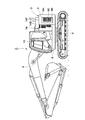
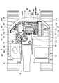
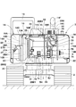
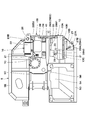
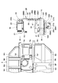
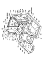
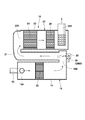
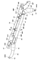
- FIG. 1 is a left side view showing a hydraulic excavator according to an embodiment of the present invention. It is the top view which looked at the excavator from the upper part in the state which omitted the exterior cover. It is the rear view which looked at the hydraulic shovel from the back in the state where a counterweight was omitted. It is a top view which shows the state which has arrange
- FIG. 5 is a partially broken exploded view showing a state in which a urea water tank, a urea water pump, a urea water supply pipe, a lateral support member, an exhaust gas purification device, and the like are removed from the swivel frame in FIG. 4.
- a hydraulic excavator 1 which is a typical example of a construction machine has a crawler type lower traveling body 2 capable of self-propelling and an upper revolving body 3 which is rotatably mounted on the lower traveling body 2. Yes.
- a working device 4 is provided on the front side of the upper swing body 3 so as to be able to move up and down. The working device 4 is used for excavating earth and sand.
- the swivel frame 5 forms a support structure that serves as a base for the upper swivel body 3.
- the revolving frame 5 is provided with a bottom plate 5A made of a thick steel plate or the like extending in the front and rear directions, and standing on the bottom plate 5A, with a predetermined interval in the left and right directions.
- the left vertical plate 5B, the right vertical plate 5C extending in the rearward direction, and the left side frame 5D extending in the front and rear directions with a space on the left side of the left vertical plate 5B, and the space on the right side of the right vertical plate 5C.
- It has a right side frame 5E which is disposed and extends rearward.
- the swivel frame 5 extends leftward from the bottom plate 5A and the left vertical plate 5B, a left extending beam 5F supporting the left side frame 5D at the leading end, and a right protruding from the bottom plate 5A and the right vertical plate 5C to the leading end. It has a right overhanging beam 5G that supports the right side frame 5E, and a rear plate 5H that extends left and right between the left side frame 5D and the rear end of the right side frame 5E.
- each engine bracket 5J On the other hand, on the rear side of the revolving frame 5, for example, four engine brackets 5J are provided between the left vertical plate 5B and the right vertical plate 5C.
- the engine 7 described later is attached to each engine bracket 5J.
- a counterweight 6 described later is attached to the rear ends of the left vertical plate 5B and the right vertical plate 5C.
- the counterweight 6 is provided on the rear side of the revolving frame 5 and balances the weight with the work device 4.
- the rear surface 6 ⁇ / b> A of the counterweight 6 is formed in an arc shape centering on the turning center of the upper swing body 3, and is configured to fit within the vehicle width of the lower traveling body 2 when the upper swing body 3 is turned.
- the engine 7 is located on the front side of the counterweight 6 and provided on the rear side of the turning frame 5.
- the engine 7 has four mounting legs 7A corresponding to the engine brackets 5J of the turning frame 5.
- Each attachment leg 7A is attached to each engine bracket 5J via an anti-vibration mount.
- the engine 7 is attached to the revolving frame 5 in a horizontally placed state in which a crankshaft (not shown) extends leftward and rightward.
- a pump mounting portion 7B is provided on the right side of the engine 7.
- a hydraulic pump 8 is attached to the pump attachment portion 7B, and an attachment base 17 of an exhaust gas purification device 16 to be described later is attached.
- a first exhaust gas aftertreatment device 18 of the exhaust gas purification device 16 is connected to the exhaust pipe 7C of the engine 7.
- the cooling fan 9 is attached to the left side of the engine 7.
- the cooling fan 9 rotates with the engine 7 as a power source, sucks external air as cooling air, and supplies this cooling air to the heat exchange device 10 described later. Cooling air from the cooling fan 9 passes through the heat exchange device 10 and flows to the engine 7 side.
- the heat exchanging device 10 is arranged upstream of the cooling fan 9 in the flow direction of the cooling air.
- the heat exchange device 10 is provided on the left rear side of the revolving frame 5 in a state of facing the cooling fan 9.
- the heat exchanging device 10 includes a support frame 10A standing on the revolving frame 5 and a radiator 10B, an oil cooler 10C, an intercooler 10D, and the like supported by the support frame 10A.
- the heat exchange device 10 cools various fluids whose temperature has risen by the cooling air supplied by the cooling fan 9. Further, the support frame 10A of the heat exchange device 10 supports the left end side of a lateral support member 34 described later at the upper position thereof.
- a hydraulic oil tank 11 and a fuel tank 12 are provided on the front side of the hydraulic pump 8 side by side in the left and right directions.
- the hydraulic oil tank 11 is formed as a rectangular parallelepiped container extending upward and downward, and stores hydraulic oil for driving various hydraulic actuators mounted on the excavator 1.
- the fuel tank 12 is disposed adjacent to the right side of the hydraulic oil tank 11.
- the fuel tank 12 is formed as a rectangular parallelepiped container extending upward and downward, and stores fuel supplied to the engine 7.
- the cab 13 is mounted on the left front side of the revolving frame 5.
- the cab 13 defines a cab in which an operator is boarded.
- a driver's seat on which an operator is seated, an operation lever for traveling, an operation lever for work, and the like (all not shown) are disposed.
- the exterior cover 14 is disposed between the counterweight 6 and the cab 13 and is provided on the revolving frame 5 in a state of extending in the left and right directions. As shown in FIG. 3, the exterior cover 14 has a left side plate 14A that covers the heat exchange device 10 and the like from the left side, a right side plate 14B that covers the hydraulic pump 8 and the like from the right side, a heat exchange device 10 and the hydraulic pump 8 and the like. 14C, an engine cover 14D, and a purification device cover 14E.
- the engine cover 14D protrudes upward from the upper surface plate 14C and covers the engine 7 and the like from above.
- the purification device cover 14E is disposed adjacent to the right side of the engine cover 14D and covers an exhaust gas purification device 16 described later.
- the purifier cover 14E is provided with a tail pipe 14F for discharging the exhaust gas to the outside so as to protrude upward.
- the machine room 15 is defined on the swivel frame 5 by the exterior cover 14, and accommodates the engine 7, the hydraulic pump 8, the cooling fan 9, the heat exchange device 10, the exhaust gas purification device 16, the urea water tank 27, and the like. is doing.
- the machine room 15 is located on the upstream side in the flow direction of the cooling air with respect to the heat exchange device 10, and on the downstream side in the flow direction of the cooling air with respect to the heat exchange device upstream chamber 15 ⁇ / b> A.
- the engine room 15B is roughly divided.
- the heat exchanger upstream chamber 15A is surrounded by the heat exchanger 10, the counterweight 6, the left side plate 14A and the top plate 14C of the outer cover 14.
- a urea water tank 27 and the like are arranged inside the heat exchange device upstream chamber 15A.
- the engine room 15B is surrounded by the heat exchange device 10, the counterweight 6, and the right side plate 14B and the top plate 14C of the exterior cover 14.
- An engine 7, a hydraulic pump 8, an exhaust gas purification device 16 and the like are disposed inside the engine chamber 15B. Cooling air from the cooling fan 9 flows from the heat exchanger upstream chamber 15A through the heat exchanger 10 to the engine chamber 15B. Therefore, the temperature in the heat exchange device upstream chamber 15A is kept lower than the temperature in the engine chamber 15B.
- the exhaust gas purification device 16 is connected to the exhaust side of the engine 7.
- the exhaust gas purification device 16 oxidizes and removes carbon monoxide (CO), hydrocarbons (HC), and the like contained in the exhaust gas discharged from the engine 7, and nitrogen oxide (NOx) contained in the exhaust gas. ) And further reduce the exhaust noise.
- the exhaust gas purification device 16 has a mounting base 17, and this mounting base 17 is mounted on the pump mounting portion 7 ⁇ / b> B of the engine 7 together with the hydraulic pump 8. As a result, the exhaust gas purification device 16 is disposed above the hydraulic pump 8.
- the exhaust gas purification device 16 includes a first exhaust gas aftertreatment device 18, a connecting pipe 21, a second exhaust gas aftertreatment device 22 and the like which will be described later.
- the first exhaust gas aftertreatment device 18 is connected to the outlet side of the exhaust pipe 7C of the engine 7.
- the first exhaust gas aftertreatment device 18 includes a cylindrical case 19 extending in the front and rear directions, and an oxidation catalyst 20 disposed in the cylindrical case 19.
- the cylindrical case 19 is formed as a cylindrical sealed container, and an air supply port 19A made of a tubular body is provided on the upstream side (front side portion) of the cylindrical case 19 so as to protrude in the radial direction.
- the outlet side of the exhaust pipe 7 ⁇ / b> C is connected to the protruding end side of the air supply port 19 ⁇ / b> A that protrudes outside the cylindrical case 19.
- An exhaust port 19 ⁇ / b> B that opens in the radial direction is provided on the downstream side (rear side portion) of the cylindrical case 19.
- the oxidation catalyst 20 is disposed in the cylindrical case 19.
- the oxidation catalyst 20 is made of, for example, a ceramic cell-shaped cylinder, and a large number of through holes are formed in the axial direction, and the inner surface is coated with a noble metal or the like.
- the oxidation catalyst 20 oxidizes and removes carbon monoxide (CO), hydrocarbons (HC), etc. contained in the exhaust gas by causing the exhaust gas to flow through each through-hole at a predetermined temperature. .
- the connecting pipe 21 connects between the first exhaust gas aftertreatment device 18 and the second exhaust gas aftertreatment device 22.
- the connecting pipe 21 is disposed on the outer peripheral side of the first exhaust gas aftertreatment device 18 and extends in the front and rear directions substantially parallel to the first exhaust gas aftertreatment device 18.
- the connection pipe 21 connects between the exhaust port 19B of the cylindrical case 19 and the air supply port 23A of the cylindrical case 23 constituting the second exhaust gas aftertreatment device 22.
- the connection pipe 21 guides the exhaust gas discharged from the first exhaust gas aftertreatment device 18 to the second exhaust gas aftertreatment device 22.
- the second exhaust gas aftertreatment device 22 is connected to the first exhaust gas aftertreatment device 18 via the connecting pipe 21.
- the second exhaust gas aftertreatment device 22 is disposed at a position overlapping the upper side of the first exhaust gas aftertreatment device 18 with the connecting pipe 21 interposed therebetween, and is substantially parallel to the first exhaust gas aftertreatment device 18. It extends in the rear direction.
- the second exhaust gas aftertreatment device 22 includes a cylindrical cylindrical case 23, a urea selective reduction catalyst 24 disposed in the cylindrical case 23, and an oxidation catalyst disposed on the downstream side of the urea selective reduction catalyst 24. 25.
- the cylindrical case 23 is formed as a sealed container by closing both ends of the cylindrical body.
- An air supply opening 23 ⁇ / b> A that opens in the radial direction is provided at a front side portion that is an upstream side of the cylindrical case 23.
- the outlet side of the connection pipe 21 is connected to the air supply port 23A.
- an exhaust port 23 ⁇ / b> B made of a tubular body is provided in the rear portion on the downstream side of the cylindrical case 23 so as to protrude radially inward from the inside of the cylindrical case 23 to the outside.
- the protruding end side of the exhaust port 23B that protrudes outside the cylindrical case 23 is connected to the tail tube 14F of the purifier cover 14E.
- a large number of through holes are provided below the exhaust port 23B disposed in the cylindrical case 23, and exhaust gas passes through each of the through holes, whereby exhaust noise is reduced (silenced).
- the urea selective reduction catalyst 24 is arranged on the upstream side of the cylindrical case 23.
- the urea selective reduction catalyst 24 is made of, for example, a ceramic cell-shaped cylindrical body, and a large number of through holes are formed in the axial direction, and the inner surface is coated with a noble metal.
- This urea selective reduction catalyst 24 selectively reduces the nitrogen oxides (NOx) contained in the exhaust gas discharged from the engine 7 with ammonia generated from the urea aqueous solution to harmless nitrogen gas and water. Decompose.
- the oxidation catalyst 25 is disposed on the downstream side of the cylindrical case 23.
- the oxidation catalyst 25 is made of a ceramic cell-like cylindrical body in substantially the same manner as the oxidation catalyst 20 described above. A large number of through holes are formed in the axial direction, and the inner surface is coated with a noble metal. As a result, the oxidation catalyst 25 oxidizes the residual ammonia remaining after the nitrogen oxides are reduced by the urea selective reduction catalyst 24 and separates it into nitrogen gas and water.
- the urea water injection valve 26 is provided in the connection pipe 21 of the exhaust gas purification device 16.
- the urea water injection valve 26 is connected to a urea water tank 27 via a urea water supply pipe 28 described later.
- the urea water injection valve 26 is disposed upstream of the urea selective reduction catalyst 24 and injects urea water (urea aqueous solution) as a reducing agent toward the exhaust gas flowing through the connection pipe 21.
- the urea water tank 27 is provided on the left rear side of the revolving frame 5. That is, the urea water tank 27 is located in the rear side of the cab 13 and is disposed in the heat exchange device upstream chamber 15A.
- the urea water tank 27 stores urea water as a reducing agent supplied to the urea water injection valve 26.
- the urea water tank 27 is arranged in the heat exchange device upstream chamber 15 ⁇ / b> A on the upstream side of the heat exchange device 10 in the flow direction of the cooling air supplied into the machine chamber 15 by the cooling fan 9. Thereby, it can suppress that the urea water in the urea water tank 27 rises in temperature by the heat which the engine 7 etc. generate
- a water supply port 27A is provided at a position corresponding to the maintenance opening 6C of the counterweight 6 on the rear side of the urea water tank 27, and urea water is supplied into the urea water tank 27 through the water supply port 27A. Further, a lid body 27B is provided on the upper side of the urea water tank 27, and one end side of a urea water supply pipe 28 to be described later is attached to the lid body 27B.
- the urea water supply pipe 28 is disposed through the machine room 15 and connects between the urea water tank 27 and the urea water injection valve 26.
- a urea water pump 31 to be described later is provided in the middle of the urea water supply pipe 28, and the urea water supply pipe 28 is a tank-side supply pipe 28 ⁇ / b> A that connects between the urea water tank 27 and the urea water pump 31.
- the urea water supply conduit 28 is formed using, for example, a flexible pressure hose, and is covered with a tubular heat insulating material 29 over the entire length thereof.
- the tubular heat insulating material 29 is formed into a cylindrical shape using, for example, a foamable resin material, and a urea water supply conduit 28 is inserted into the tubular heat insulating material 29. Thereby, the tubular heat insulating material 29 shields the urea water supply conduit 28 from heat.
- the tank side supply line 28A has a tank side downward line 28A1 and a tank side side line 28A2.
- the tank-side downward conduit 28A1 extends downward from the urea water tank 27 to the bottom plate 5A of the revolving frame 5.
- the tank side lateral pipe 28A2 extends laterally from the lower end of the tank side downward pipe 28A1 to the urea water pump 31 through the lower side of the heat exchange device 10.
- a portion of the tank side lateral pipe 28 ⁇ / b> A ⁇ b> 2 disposed in the engine chamber 15 ⁇ / b> B is formed by a large-diameter tubular heat insulating material 30 formed into a large-diameter cylindrical shape using a resin material thicker than the tubular heat insulating material 29. Covered. That is, a portion of the tank side lateral pipe 28 ⁇ / b> A ⁇ b> 2 that is disposed in the engine chamber 15 ⁇ / b> B is doubly covered with the tubular heat insulating material 29 and the large-diameter tubular heat insulating material 30. Thus, the urea water flowing through the tank side supply pipe 28A is shielded from heat so that the temperature does not rise due to heat generated by the engine 7 and the like.
- the injection valve side supply line 28B has an injection valve side backward line 28B1, an injection valve side upward line 28B2, and an injection valve side side line 28B3.
- the injection valve side rearward conduit 28B1 extends rearward from the urea water pump 31 to the rear plate 5H along the left vertical plate 5B of the swivel frame 5.
- the injection valve side upward pipe 28B2 extends upward along the front surface 6B of the counterweight 6 from the rear end of the injection valve side rear pipe 28B1.
- the injection valve side lateral pipe 28B3 extends rightward from the upper end of the injection valve side upward pipe 28B2 to the urea water injection valve 26 along the upper end of the counterweight 6.
- the injection valve side rearward conduit 28B1 and the injection valve side upward conduit 28B2 are further covered with a large-diameter tubular heat insulating material 30 disposed on the outer peripheral side of the tubular heat insulating material 29. That is, the injection valve side rearward pipe line 28B1 and the injection valve side upward pipe line 28B2 arranged in the engine chamber 15B are double-covered by the tubular heat insulating material 29 and the large-diameter tubular heat insulating material 30. Accordingly, the urea water flowing through the injection valve side supply pipe 28B is shielded from heat so that the temperature does not rise due to heat generated by the engine 7 and the like.
- the injection valve side lateral pipe 28B3 of the urea water supply pipe 28 is normally disposed in the upper region of the engine chamber 15B that becomes a dead space, thereby effectively making this dead space. Can be used. However, the heat generated by the engine 7, the hydraulic pump 8, etc. stays in the upper region of the engine chamber 15B. For this reason, the injection valve side lateral pipe 28B3 extending in the left and right directions along the upper end of the counterweight 6 is easily affected by heat from the engine 7 and the like.
- the injection valve side lateral pipe 28B3 of the injection valve side supply pipe 28B is in a pipe housing space 41 formed by a lateral support member 34 and a heat shield cover 38 which will be described later. Contained.
- the urea water pump 31 is located on the left side of the left vertical plate 5B of the revolving frame 5 and is disposed on the bottom plate 5A.
- the urea water pump 31 pumps the urea water stored in the urea water tank 27 toward the urea water injection valve 26.
- a tank-side supply line 28A (tank-side lateral line 28A2) is connected to the suction side of the urea water pump 31, and an injection valve-side supply line 28B (injection valve-side backward) is connected to the discharge side of the urea water pump 31.
- Pipe line 28B1) is connected.
- the support member 32 is disposed on the front side of the counterweight 6 and supports the exterior cover 14. As shown in FIGS. 3 and 6, the support member 32 includes a plurality of vertical support members 33 (only two are shown) whose lower ends are fixed to the rear plate 5H of the revolving frame 5 and which extend upward and downward, and horizontal supports.
- the member 34 is comprised.
- the horizontal support member 34 is connected to the upper position of the support frame 10 ⁇ / b> A of the heat exchange device 10 and the upper position of the vertical support member 33, and extends left and right along the upper end of the counterweight 6.
- the lateral support member 34 is formed using a steel plate material or the like bent into an inverted L shape. Specifically, the lateral support member 34 is bent forward from the front plate 34A extending in the left and right directions while facing the front surface 6B of the counterweight 6 with a gap in the front and rear directions, and the upper end of the front plate 34A. And an upper surface plate 34B. On both sides in the length direction (left and right directions) of the upper surface plate 34B, cutout portions 34C that are notched in a rectangular shape from the front edge of the upper surface plate 34B toward the front surface plate 34A are formed. A cover mounting plate 34D that is inclined obliquely downward from the front plate 34A toward the front is fixed to each of the notches 34C. The engine cover 14D is attached to each cover attachment plate 34D via a hinge member (not shown).
- a bracket 34E protruding to the left is integrally formed on the left end side of the front plate 34A, and two bolt insertion portions 34F are provided on the bracket 34E.
- a bolt insertion hole 34G is provided on the right end side of the upper surface plate 34B.
- the lateral support member 34 screws the bolt 35 inserted into the bolt insertion portion 34F of the bracket 34E into the upper position of the support frame 10A of the heat exchange device 10, and A bolt (not shown) inserted through the bolt insertion hole 34 ⁇ / b> G is screwed into the upper position of the vertical support member 33.
- the horizontal support member 34 is fixed between the support frame 10 ⁇ / b> A of the heat exchange device 10 and the vertical support member 33. Further, two bolt insertion holes 34H for attaching a heat shield cover 38 to be described later are provided between the notches 34C in the upper surface plate 34B.
- the opening 36 is provided in the front plate 34 ⁇ / b> A facing the front surface 6 ⁇ / b> B of the counterweight 6.
- the opening 36 is formed by a rectangular square hole extending in the left and right directions, and opens a duct housing space 41 described later to the outside air.
- the horizontal support member 34 is provided with a plurality of columnar heat insulating materials 37 located on the surface facing the front surface 6 ⁇ / b> B of the counterweight 6.
- the columnar heat insulating material 37 is formed in a quadrangular column shape using, for example, a foamable resin material, and is attached so as to surround the opening 36. As shown in FIG.
- each columnar heat insulating material 37 partitions between the engine compartment 15 ⁇ / b> B and the opening 36 by contacting the front surface 6 ⁇ / b> B of the counterweight 6. Thereby, hot air in the engine chamber 15 ⁇ / b> B is prevented from flowing into the pipe line accommodating space 41 through the opening 36.
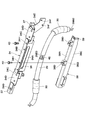
- the heat shield cover 38 is attached to the lateral support member 34, and forms a pipe accommodating space 41 described later between the thermal support cover 34 and the lateral support member 34. As shown in FIGS. 9 and 11, the heat shield cover 38 is formed by using a steel plate material or the like bent into a U shape, and extends left and right along the lateral support member 34.
- the heat shield cover 38 is an upper surface plate 38A that faces the upper surface plate 34B of the lateral support member 34 in the upward and downward directions, a front surface plate 38B that extends downward from the front end of the upper surface plate 38A, and a rear surface that extends rearward from the lower end of the front surface plate 38B.
- the front plate 38B faces the front plate 34A of the lateral support member 34 in the front and rear directions with a gap.
- the bottom plate 38C faces the top plate 38A in the upward and downward directions with a gap.
- Screw seats 38 ⁇ / b> D having female screw holes are fixed to two portions of the upper surface plate 38 ⁇ / b> A corresponding to the bolt insertion holes 34 ⁇ / b> H of the lateral support member 34 by means such as welding.
- a plate-like heat insulating material 39 formed in a thin plate shape using, for example, a foamable resin material is attached to the inner side surface of the heat shield cover 38 on the pipe housing space 41 side.
- the heat insulating cover 38 is fixed to the lateral support member 34 by screwing the bolts 40 inserted into the respective bolt insertion holes 34H of the lateral support member 34 into the respective screw seats 38D of the heat insulating cover 38.
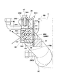
- a pipe housing space 41 having a quadrangular cross section is formed between the lateral support member 34 and the heat shield cover 38.
- a lateral pipe 28B3 is accommodated.
- the injection valve side lateral pipe 28B3 accommodated in the pipe accommodation space 41 is covered with a tubular heat insulating material 29, and the outer peripheral side of the tubular heat insulating material 29 is each plate-like attached to the inner side surface of the heat insulating cover 38. It is further covered with a heat insulating material 39. Therefore, the injection valve side lateral pipe 28 ⁇ / b> B ⁇ b> 3 housed in the pipe housing space 41 is double covered with the tubular heat insulating material 29 and the plate heat insulating material 39.
- the hot air B radiated from the engine 7 or the like toward the injection valve side supply pipe 28B can be blocked by the heat shield cover 38.
- the temperature rise of the urea water which flows through the injection valve side horizontal pipe line 28B3 accommodated in the pipe line accommodation space 41 can be suppressed.
- the pipe accommodation space 41 is always open to the outside air through the opening 36 provided in the lateral support member 34, the pipe accommodation space 41 does not become a closed cross-sectional space. Thereby, even if hot air is generated in the pipe accommodating space 41, it is possible to suppress the hot air from flowing into the pipe accommodating space 41 by releasing the hot air A into the outside air through the opening 36.
- a cooling water pipe 42 through which a part of the engine cooling water flows is arranged. Accordingly, for example, in cold districts, the injection valve side lateral pipe 28B3 can be warmed as necessary using engine cooling water flowing through the cooling water pipe 42, and urea flowing through the injection valve side horizontal pipe 28B3 can be used. The water can be prevented from freezing.
- the hydraulic excavator 1 has the above-described configuration, and the operation thereof will be described below.
- the hydraulic pump 8 When the operator who has boarded the cab 13 starts the engine 7, the hydraulic pump 8 is driven. Pressure oil from the hydraulic pump 8 is supplied to various hydraulic actuators mounted on the hydraulic excavator 1. In this state, the lower traveling body 2 can be moved forward or backward by the operator operating the operating lever for traveling. Moreover, when the operator operates the operation lever for work, excavation work of earth and sand can be performed using the work device 4 while turning the upper swing body 3.
- the oxidation catalyst 20 provided in the first exhaust gas aftertreatment device 18 has carbon monoxide (CO) and hydrocarbon (HC) in the exhaust gas discharged from the engine 7. Etc. are oxidized and removed.
- the urea selective reduction catalyst 24 provided in the second exhaust gas post-treatment device 22 harms nitrogen oxides (NOx) in the exhaust gas by injecting urea water from the urea water injection valve 26. Decomposes into nitrogen gas and water.
- the oxidation catalyst 25 provided in the second exhaust gas aftertreatment device 22 oxidizes and removes residual ammonia. In this way, the exhaust gas from the engine 7 is purified by the exhaust gas purification device 16. The purified exhaust gas is discharged into the atmosphere through the tail pipe 14F of the purification device cover 14E.
- the urea water tank 27 for storing urea water is disposed in the heat exchange device upstream chamber 15A on the upstream side of the heat exchange device 10 in the flow direction of the cooling air.
- the urea water tank 27 is not exposed to the heat from the engine 7 or the like, or the cooling air heated through the heat exchange device 10. Therefore, the temperature rise of the urea water stored in the urea water tank 27 can be suppressed, and the properties of the urea water can be kept appropriate.
- the injection valve side lateral pipe 28 ⁇ / b> B ⁇ b> 3 constituting the injection valve side supply pipe 28 ⁇ / b> B is the counterweight 6.
- the injection valve side lateral pipe 28B3 disposed in the upper region of the engine chamber 15B is easily affected by heat from the engine 7 or the like.
- the heat insulating cover 38 is attached to the existing lateral support member 34 provided in the upper region of the engine chamber 15B among the support members 32 that support the exterior cover 14. Thereby, a pipe accommodating space 41 is formed between the lateral support member 34 and the heat shield cover 38, and the injection valve side lateral pipe 28 ⁇ / b> B ⁇ b> 3 can be accommodated in the pipe accommodating space 41.
- the injection valve side side pipe 28B3 that is easily affected by heat from the engine 7 or the like is provided.
- the horizontal support member 34 and the heat shield cover 38 can shield from the hot air B.
- the opening 36 is provided in the lateral support member 34, the pipe space 41 is always open to the outside air through the opening 36. Therefore, it is possible to prevent the hot air from flowing inside the pipe housing space 41 as a closed cross-sectional space, and even if hot air A is generated in the pipe housing space 41, the hot air A passes through the opening 36 to the outside air. Released into. As a result, hot air does not flow in the pipe accommodating space 41, and the temperature rise of the urea water flowing through the injection valve side lateral pipe 28B3 can be reliably suppressed.
- the opening 36 of the lateral support member 34 opens at a portion facing the front surface 6B of the counterweight 6. As a result, rainwater, earth and sand, etc. can be prevented from entering the pipe accommodating space 41 through the opening 36.
- the injection valve side lateral pipe 28B3 accommodated in the pipe accommodation space 41 is covered with a tubular heat insulating material 29. Thereby, the injection valve side lateral pipe 28B3 can be further shielded from the heat of the engine 7, and the temperature rise of the urea water can be efficiently suppressed.
- the case where only the oxidation catalyst 20 is provided in the cylindrical case 19 of the first exhaust gas aftertreatment device 18 is illustrated.
- the present invention is not limited to this.
- a particulate matter removing filter Diesel Particulate Filter, It is good also as a structure which provides (it is also called DPF for short).
- the hydraulic excavator 1 including the crawler type lower traveling body 2 is described as an example of the construction machine.
- the present invention is not limited to this.
- the present invention may be applied to a hydraulic excavator provided with a wheel-type lower traveling body, and may be widely applied to other construction machines such as a hydraulic crane.
Landscapes
- Engineering & Computer Science (AREA)
- General Engineering & Computer Science (AREA)
- Mining & Mineral Resources (AREA)
- Civil Engineering (AREA)
- Structural Engineering (AREA)
- Mechanical Engineering (AREA)
- Chemical & Material Sciences (AREA)
- Combustion & Propulsion (AREA)
- Transportation (AREA)
- Chemical Kinetics & Catalysis (AREA)
- Health & Medical Sciences (AREA)
- Toxicology (AREA)
- Exhaust Gas After Treatment (AREA)
- Component Parts Of Construction Machinery (AREA)
Priority Applications (4)
| Application Number | Priority Date | Filing Date | Title |
|---|---|---|---|
| US15/757,235 US10323557B2 (en) | 2015-10-06 | 2016-09-07 | Construction machine |
| EP16853377.6A EP3361011B1 (en) | 2015-10-06 | 2016-09-07 | Construction machine with exhaust gas treatment system |
| KR1020187006480A KR102057634B1 (ko) | 2015-10-06 | 2016-09-07 | 건설기계 |
| CN201680050717.4A CN107923142B (zh) | 2015-10-06 | 2016-09-07 | 工程机械 |
Applications Claiming Priority (2)
| Application Number | Priority Date | Filing Date | Title |
|---|---|---|---|
| JP2015198415A JP6560587B2 (ja) | 2015-10-06 | 2015-10-06 | 建設機械 |
| JP2015-198415 | 2015-10-06 |
Publications (1)
| Publication Number | Publication Date |
|---|---|
| WO2017061223A1 true WO2017061223A1 (ja) | 2017-04-13 |
Family
ID=58487589
Family Applications (1)
| Application Number | Title | Priority Date | Filing Date |
|---|---|---|---|
| PCT/JP2016/076312 Ceased WO2017061223A1 (ja) | 2015-10-06 | 2016-09-07 | 建設機械 |
Country Status (6)
| Country | Link |
|---|---|
| US (1) | US10323557B2 (cg-RX-API-DMAC7.html) |
| EP (1) | EP3361011B1 (cg-RX-API-DMAC7.html) |
| JP (1) | JP6560587B2 (cg-RX-API-DMAC7.html) |
| KR (1) | KR102057634B1 (cg-RX-API-DMAC7.html) |
| CN (1) | CN107923142B (cg-RX-API-DMAC7.html) |
| WO (1) | WO2017061223A1 (cg-RX-API-DMAC7.html) |
Families Citing this family (15)
| Publication number | Priority date | Publication date | Assignee | Title |
|---|---|---|---|---|
| JP6414488B2 (ja) * | 2015-03-05 | 2018-10-31 | いすゞ自動車株式会社 | 排気浄化装置のメンテナンス用具、及びメンテナンス方法 |
| JP6497737B2 (ja) * | 2015-06-18 | 2019-04-10 | キャタピラー エス エー アール エル | 建設機械におけるカウンタウエイト支持構造 |
| CN107923141B (zh) * | 2016-03-10 | 2020-06-12 | 日立建机株式会社 | 工程机械 |
| JP6934439B2 (ja) * | 2018-03-19 | 2021-09-15 | 日立建機株式会社 | 建設機械 |
| JP7273619B2 (ja) * | 2018-06-01 | 2023-05-15 | マニタウォック クレイン カンパニーズ, エルエルシー | クレーン下部走行体上のエンジン排気後処理システムのための取り付け配設 |
| CN109056862B (zh) * | 2018-09-27 | 2021-05-07 | 景冲 | 一种挖掘机动臂 |
| CN108978745B (zh) * | 2018-09-28 | 2021-05-28 | 景冲 | 一种具有稳定油路的挖掘机 |
| USD986983S1 (en) * | 2018-12-12 | 2023-05-23 | Bruder Spielwaren Gmbh + Co. Kg | Toy |
| JP7039517B2 (ja) * | 2019-03-22 | 2022-03-22 | 株式会社日立建機ティエラ | 建設機械 |
| CN110344465A (zh) * | 2019-06-28 | 2019-10-18 | 三一重机有限公司 | 工程机械 |
| JP6922960B2 (ja) * | 2019-09-26 | 2021-08-18 | コベルコ建機株式会社 | 建設機械 |
| US12152521B2 (en) | 2020-01-22 | 2024-11-26 | Cnh Industrial America Llc | System for cooling a diesel exhaust fluid |
| JP7424736B2 (ja) * | 2020-03-06 | 2024-01-30 | キャタピラー エス エー アール エル | 機体および作業機械 |
| EP4286197A4 (en) * | 2021-06-30 | 2025-01-01 | Hitachi Construction Machinery Co., Ltd. | Construction machine |
| JP7710390B2 (ja) * | 2022-02-28 | 2025-07-18 | ヤンマーホールディングス株式会社 | 作業機械 |
Citations (4)
| Publication number | Priority date | Publication date | Assignee | Title |
|---|---|---|---|---|
| JP2010261373A (ja) * | 2009-05-08 | 2010-11-18 | Kobelco Contstruction Machinery Ltd | 作業機械 |
| WO2013128689A1 (ja) * | 2012-02-29 | 2013-09-06 | 株式会社小松製作所 | 作業機械 |
| JP2014080907A (ja) * | 2012-10-16 | 2014-05-08 | Komatsu Ltd | 油圧ショベル |
| JP2015001159A (ja) * | 2013-06-13 | 2015-01-05 | キャタピラー エス エー アール エル | 建設機械における還元剤用配管の配設構造 |
Family Cites Families (6)
| Publication number | Priority date | Publication date | Assignee | Title |
|---|---|---|---|---|
| JP4989999B2 (ja) * | 2007-03-28 | 2012-08-01 | 株式会社小松製作所 | 建設車両 |
| JP2009138526A (ja) | 2007-12-03 | 2009-06-25 | Hitachi Constr Mach Co Ltd | 建設機械 |
| JP5698543B2 (ja) | 2011-01-14 | 2015-04-08 | 日立建機株式会社 | 建設機械の尿素水タンク構造 |
| JP5449517B1 (ja) | 2012-12-20 | 2014-03-19 | 株式会社小松製作所 | 作業車両 |
| CN104185723B (zh) * | 2013-03-26 | 2015-11-25 | 株式会社小松制作所 | 作业车辆及轮式装载机 |
| JP2015021398A (ja) * | 2013-07-16 | 2015-02-02 | キャタピラー エス エー アール エル | 機体および作業機械 |
-
2015
- 2015-10-06 JP JP2015198415A patent/JP6560587B2/ja active Active
-
2016
- 2016-09-07 KR KR1020187006480A patent/KR102057634B1/ko active Active
- 2016-09-07 CN CN201680050717.4A patent/CN107923142B/zh active Active
- 2016-09-07 WO PCT/JP2016/076312 patent/WO2017061223A1/ja not_active Ceased
- 2016-09-07 EP EP16853377.6A patent/EP3361011B1/en active Active
- 2016-09-07 US US15/757,235 patent/US10323557B2/en active Active
Patent Citations (4)
| Publication number | Priority date | Publication date | Assignee | Title |
|---|---|---|---|---|
| JP2010261373A (ja) * | 2009-05-08 | 2010-11-18 | Kobelco Contstruction Machinery Ltd | 作業機械 |
| WO2013128689A1 (ja) * | 2012-02-29 | 2013-09-06 | 株式会社小松製作所 | 作業機械 |
| JP2014080907A (ja) * | 2012-10-16 | 2014-05-08 | Komatsu Ltd | 油圧ショベル |
| JP2015001159A (ja) * | 2013-06-13 | 2015-01-05 | キャタピラー エス エー アール エル | 建設機械における還元剤用配管の配設構造 |
Also Published As
| Publication number | Publication date |
|---|---|
| KR20180038497A (ko) | 2018-04-16 |
| JP6560587B2 (ja) | 2019-08-14 |
| EP3361011A4 (en) | 2019-05-01 |
| JP2017071927A (ja) | 2017-04-13 |
| EP3361011B1 (en) | 2020-08-19 |
| EP3361011A1 (en) | 2018-08-15 |
| KR102057634B1 (ko) | 2019-12-19 |
| CN107923142B (zh) | 2020-10-30 |
| US20180274423A1 (en) | 2018-09-27 |
| CN107923142A (zh) | 2018-04-17 |
| US10323557B2 (en) | 2019-06-18 |
Similar Documents
| Publication | Publication Date | Title |
|---|---|---|
| JP6560587B2 (ja) | 建設機械 | |
| JP5764725B1 (ja) | 油圧ショベル | |
| CN103890276B (zh) | 液压挖掘机 | |
| WO2017061207A1 (ja) | 建設機械 | |
| JPWO2014155510A1 (ja) | ホイールローダ | |
| KR101834979B1 (ko) | 건설 기계 | |
| JP6093983B2 (ja) | 建設機械 | |
| JP6071855B2 (ja) | 建設機械 | |
| JP5723493B1 (ja) | 油圧ショベル | |
| JP2019162925A (ja) | 建設機械 | |
| JPWO2016021047A1 (ja) | 油圧ショベル | |
| JP2020019402A (ja) | 建設機械 | |
| JP5723494B1 (ja) | 油圧ショベル | |
| JP7271745B2 (ja) | 建設機械 | |
| JP5782219B2 (ja) | エンジン装置 | |
| JP2016138370A (ja) | 建設機械 | |
| JP7594407B2 (ja) | 建設機械 | |
| JP7545859B2 (ja) | 建設機械 | |
| JP6549455B2 (ja) | ショベル | |
| JP2019163733A (ja) | 排気ガス浄化装置 | |
| JP6495196B2 (ja) | 建設機械 | |
| WO2025204331A1 (ja) | 建設機械 | |
| JP2017053330A (ja) | 建設機械 | |
| KR101578337B1 (ko) | 유압 셔블 |
Legal Events
| Date | Code | Title | Description |
|---|---|---|---|
| 121 | Ep: the epo has been informed by wipo that ep was designated in this application |
Ref document number: 16853377 Country of ref document: EP Kind code of ref document: A1 |
|
| WWE | Wipo information: entry into national phase |
Ref document number: 15757235 Country of ref document: US |
|
| ENP | Entry into the national phase |
Ref document number: 20187006480 Country of ref document: KR Kind code of ref document: A |
|
| NENP | Non-entry into the national phase |
Ref country code: DE |