WO2017061202A1 - 固定装置 - Google Patents
固定装置 Download PDFInfo
- Publication number
- WO2017061202A1 WO2017061202A1 PCT/JP2016/075932 JP2016075932W WO2017061202A1 WO 2017061202 A1 WO2017061202 A1 WO 2017061202A1 JP 2016075932 W JP2016075932 W JP 2016075932W WO 2017061202 A1 WO2017061202 A1 WO 2017061202A1
- Authority
- WO
- WIPO (PCT)
- Prior art keywords
- storage
- battery
- body case
- main body
- protrusion
- Prior art date
- Legal status (The legal status is an assumption and is not a legal conclusion. Google has not performed a legal analysis and makes no representation as to the accuracy of the status listed.)
- Ceased
Links
Images






Classifications
-
- H—ELECTRICITY
- H01—ELECTRIC ELEMENTS
- H01M—PROCESSES OR MEANS, e.g. BATTERIES, FOR THE DIRECT CONVERSION OF CHEMICAL ENERGY INTO ELECTRICAL ENERGY
- H01M50/00—Constructional details or processes of manufacture of the non-active parts of electrochemical cells other than fuel cells, e.g. hybrid cells
- H01M50/20—Mountings; Secondary casings or frames; Racks, modules or packs; Suspension devices; Shock absorbers; Transport or carrying devices; Holders
- H01M50/202—Casings or frames around the primary casing of a single cell or a single battery
-
- H—ELECTRICITY
- H01—ELECTRIC ELEMENTS
- H01M—PROCESSES OR MEANS, e.g. BATTERIES, FOR THE DIRECT CONVERSION OF CHEMICAL ENERGY INTO ELECTRICAL ENERGY
- H01M50/00—Constructional details or processes of manufacture of the non-active parts of electrochemical cells other than fuel cells, e.g. hybrid cells
- H01M50/20—Mountings; Secondary casings or frames; Racks, modules or packs; Suspension devices; Shock absorbers; Transport or carrying devices; Holders
- H01M50/271—Lids or covers for the racks or secondary casings
-
- H—ELECTRICITY
- H01—ELECTRIC ELEMENTS
- H01M—PROCESSES OR MEANS, e.g. BATTERIES, FOR THE DIRECT CONVERSION OF CHEMICAL ENERGY INTO ELECTRICAL ENERGY
- H01M50/00—Constructional details or processes of manufacture of the non-active parts of electrochemical cells other than fuel cells, e.g. hybrid cells
- H01M50/20—Mountings; Secondary casings or frames; Racks, modules or packs; Suspension devices; Shock absorbers; Transport or carrying devices; Holders
- H01M50/289—Mountings; Secondary casings or frames; Racks, modules or packs; Suspension devices; Shock absorbers; Transport or carrying devices; Holders characterised by spacing elements or positioning means within frames, racks or packs
- H01M50/291—Mountings; Secondary casings or frames; Racks, modules or packs; Suspension devices; Shock absorbers; Transport or carrying devices; Holders characterised by spacing elements or positioning means within frames, racks or packs characterised by their shape
Definitions
- This disclosure relates to a fixing device that fixes an object inside.
- the battery pack In devices having a battery pack such as a portable terminal and a camera, the battery pack is configured to be detachable.
- the battery pack is stored in a storage unit included in the main body case. And the battery pack is being fixed to the storage part so that the stored battery pack may not remove easily.
- a fixing structure for fixing the battery pack there is a structure in which the battery pack itself is held in the main body case to receive a force in the pop-out direction of the battery pack (see, for example, Patent Document 1). Further, there is a structure in which the battery pack is held by the lid instead of the main body case, and the lid is held by the main body case. In the structure in which the battery pack is held by the lid, the battery pack is prevented from popping out by the lid.
- a groove having an L-shaped cross section is provided in the main body case, and a protrusion provided on the battery pack or the lid is fitted into the L-shaped groove, so that the force in the protruding direction of the battery pack or the lid is perpendicular. is recieving.
- the battery pack fixing structure in the emergency call device needs to have impact resistance.
- the lid and the main body case can be firmly fastened by fastening the lid to the main body case with screws.
- fastening with a fastening member such as a screw increases the cost and deteriorates the workability of battery replacement in the vehicle.
- the lid is fixed to the case body by a snap fit.
- a groove or a pin is provided in the main body case, and a pin or a groove is provided in the battery pack. Then, the battery pack can be inserted into the main body case and then slid to have a fixing function. Further, when removing the battery pack, the battery pack can be removed by performing the reverse operation.
- the present disclosure has been made in view of the above points, and an object thereof is to provide a fixing device that can be miniaturized and can fix an object inside.
- the fixing device of the present disclosure includes a main body case in which a storage space for storing an object is formed, and a lid that contacts the main body case and covers the storage space in a state in which the target object is stored in the storage space.
- the main body case is formed with either a protrusion or a groove with which the protrusion engages. Either the projection or the groove is formed on the object.
- the groove has a storage portion that extends in the storage direction for storing the object in the storage space, and an installation portion that extends in the intersecting direction that intersects the storage direction.
- the installation portion extends in an intersecting direction from an end portion of the storage portion in the storage direction.
- the lid has a restricting portion that comes into contact with the object while covering the storage space. In the fixed state in which the object is fixed in the main body case, the protrusion is engaged with the installation portion. The displacement of the object in the direction opposite to the intersecting direction with respect to the main body case is restricted by the restricting portion.
- the protrusion in a fixed state in which the object is fixed in the main body case, the protrusion is engaged with the installation portion. This restricts the protrusion from being displaced in the storage direction and in the opposite direction. Further, in the fixed state, the displacement of the object in the direction opposite to the intersecting direction with respect to the main body case is restricted by the restriction part of the lid. As a result, the displacement of the object in the storage direction and the crossing direction is restricted, so that the object can be reliably fixed in the storage space.
- the position of the object in the storage space is adjusted so that the storage portion of the groove and the protrusion are engaged.
- the lid is arranged, the object is pushed by the lid regulating portion, and the protrusion is engaged with the installation portion extending in the crossing direction. Therefore, the object can be fixed simply by placing the object in the storage space and covering the object. This makes it possible to fix the object with a simple operation. Further, since there is no need for a knob or a pressing surface for placing the object on the installation portion, it is possible to reduce the size of the fixing device.
- FIG. 15 is a cross-sectional view seen from the section line XV in FIG. 14.
- An in-vehicle emergency call device 10 shown in FIG. 1 is a device for making an emergency call to an emergency call center as a report destination when an emergency such as a vehicle collision occurs.
- Examples of the emergency call device 10 for a vehicle include a communication module used for a telematics service such as DCM (Data Communication Module).
- the emergency call device 10 is supplied with power from the main battery and the backup battery 11.
- the main battery is a main power source that supplies electric power to each electric load (each electric device) of the vehicle, and can also be used as a power source that supplies electric power to the starter when the engine is started. Further, the main battery is also a main power source of the emergency notification device 10.
- the main battery is composed of a lead storage battery. It should be noted that the power supply from the main battery may be enabled when the accessory (ACC) power source of the vehicle is on.
- the backup battery 11 is a sub power source that supplies power to at least the emergency call device 10 as an alternative power source for the main battery.
- the backup battery 11 is used as a power source when the main battery itself is damaged due to, for example, a traffic accident or the power supply line from the main battery is disconnected, so that the power supply from the main battery becomes impossible. Function.
- the backup battery 11 is composed of a detachable secondary battery.
- a secondary battery that can operate in a temperature environment of about ⁇ 30 ° C. to + 85 ° C. and has a long life is used.
- a lithium ion secondary battery and a lithium ion polymer secondary battery are used.
- a lithium ion secondary battery or the like can be used at low temperatures because it uses an organic solvent having a melting point lower than that of water.
- lithium ion secondary batteries and the like have much better self-discharge characteristics and longer life than other secondary batteries such as nickel-cadmium batteries and nickel-metal hydride batteries.
- lithium ion secondary batteries and the like can be miniaturized and have few restrictions on mounting.
- the structure using secondary batteries other than lithium ion secondary batteries, such as a nickel hydride secondary battery, and a lithium ion polymer secondary battery as the backup battery 11 may be sufficient.
- Such a backup battery (hereinafter sometimes referred to as a battery) 11 is covered with a lid 13 after being attached to the main body case 12. As a result, the surface of the battery 11 is housed inside the main body case 12 without being exposed.
- the fixing device for the battery 11 in the emergency call device 10 in consideration of the restrictions (1) to (6) will be described.
- the fixing device includes a battery 11, a main body case 12, and a lid 13.
- the battery 11 is a longitudinal component having a rectangular parallelepiped outer shape, specifically, a flat upper surface and a semicircular lower surface.
- a storage space 12 b for storing the battery 11 is formed inside the main body case 12.
- the storage space 12b has a shape in which no gap is formed around the battery 11 in a state where the battery 11 is stored in the storage space 12b, or a small gap is formed. Yes.
- the lid 13 contacts the main body case 12 and covers the storage space 12b in a state where the battery 11 is stored in the storage space 12b.
- the direction in which the rectangular parallelepiped battery 11 extends is referred to as a longitudinal direction X.
- the direction in which the battery 11 is attached is the attachment direction X1
- the direction in which the battery 11 is removed is the removal direction X2. Therefore, the attachment direction X1 and the removal direction X2 are opposite directions.
- the direction that intersects the longitudinal direction X and is orthogonal in the present embodiment, and is the direction in which the battery 11 is mounted and removed is referred to as the up-down direction Z.
- the direction when the battery 11 is attached to the storage space 12b is the downward direction Z1
- the direction of removal from the storage space 12b is the upward direction Z2. Therefore, the downward direction Z1 and the upward direction Z2 are opposite directions.
- a direction orthogonal to the vertical direction Z and the longitudinal direction X is referred to as a width direction Y.
- the battery 11 has a pin 31 formed as a protrusion.
- the main body case 12 has a groove 22 with which the pin 31 engages.
- the pin 31 is a side surface of the battery 11, and a plurality of pins 31 are formed on the side surface extending in the longitudinal direction X, and four pins are formed in the longitudinal direction X in the present embodiment. Two pins 31 are formed on each side surface.
- the pin 31 has a cylindrical outer shape and is configured to be in line contact with the groove 22.
- the battery 11 is provided with a cord 33 at the end on the side of the mounting direction X1.
- a connector 34 is connected to the tip of the cord 33.
- a plurality of grooves 22 are formed at intervals in the longitudinal direction X on the side wall 23 forming the storage space 12b.
- four grooves 22 are formed, and each of two opposing side walls 23 has two grooves 22.
- the groove 22 has a storage portion 24 extending in the downward direction Z ⁇ b> 1, an inclined portion 25 extending in the inclined direction, and an installation portion 26 extending in the longitudinal direction X. Accordingly, the groove 22 is L-shaped when viewed from the side.
- the storage portion 24 of the groove 22 is wide open in the upward direction Z2, and is formed so that the interval becomes narrower as it proceeds in the downward direction Z1.
- a relief shape is formed at the entrance of the groove 22 so as not to interfere with the pin 31.
- the inclined portion 25 of the groove 22 extends from the lower end of the storage portion 24 so as to advance in the mounting direction X1 as it proceeds in the downward direction Z1.
- the inclined portion 25 extends so that the distance in the mounting direction (intersection direction) X1 between the lower end of the storage portion 24 and the inclined portion 25 becomes shorter in the downward direction (storage direction) Z1.
- the inclined portion 25 extends so that the distance in the longitudinal direction X between the lower end portion of the storage portion 24 and the inclined portion 25 becomes longer in the upward direction Z2.
- the direction in which the inclined portion 25 extends is the inclined direction.
- the inclined portion 25 connects the storage portion 24 and the installation portion 26.
- the installation portion 26 of the groove 22 extends from the end of the inclined portion 25 in the inclined direction in the mounting direction X1.
- at least a portion where the pins 31 are arranged in a fixed state is set to have the same vertical dimension Z as the outer shape of the pins 31 or a dimension capable of light press-fitting.
- Step portions 27 are formed in the two grooves 22 on the removal direction X2 side.
- the step portion 27 is formed in a part of the storage portion 24, and has a flat surface 27a extending in the longitudinal direction X and a regulating surface 27b that regulates displacement in the removal direction X2.
- the flat surface 27 a of the stepped portion 27 has a length that allows the pin 31 to be placed thereon.
- the interval in the longitudinal direction X of the storage portion 24 is widened.
- the interval in the longitudinal direction X of the storage portion 24 of the two grooves 22 on the mounting direction X1 side is set to be slightly larger than the outer shape of the pin 31.
- the storage portion 24 extending in the up-down direction Z on the attachment direction X1 side is set to be narrow enough to allow the pin 31 to pass through.
- the convex part 32 is formed in the side surface which is the removal direction X2 side among the batteries 11, and contains the up-down direction Z and the width direction Y.
- FIG. 5 the convex portion 32 is formed at the end portion on the side in the upward direction Z ⁇ b> 2 and protrudes in the removal direction X ⁇ b> 2.
- the main body case 12 is formed with the water stop rib 21 used as a support part.
- the convex portion 32 is positioned in the upward direction Z2 of the water blocking rib 21, as shown in FIG. In other words, the convex portion 32 is formed on the upper portion of the battery 11 so as to overlap the water stop rib 21.
- the inclined portion 25 of the groove 22 is positioned in a state where the convex portion 32 is hooked immediately above the water blocking rib 21 and when the battery 11 is in a horizontal posture, that is, in the state shown in FIG.
- the starting point of the inclined portion 25 is formed from the place where 31 is located. And in order to remove the battery 11, when displacing the side surface by the side of the attachment direction X1 to the upper direction Z2, the convex part 32 and the water stop rib 21 contact, and it becomes a fulcrum.
- the lid 13 is plate-shaped, has an engaging claw 41 at the end on the attachment direction X1 side, and has a snap fit portion 42 at the end on the removal direction X2 side.
- an engagement recess 28 that engages with the engagement claw 41 is provided at the end on the attachment direction X ⁇ b> 1 side.
- a receiving portion 29 to which the snap fit portion 42 engages is provided at the end portion on the removal direction X2 side.
- the engaging claw 41 can be inserted into the engaging recess 28 from an oblique direction inclined with respect to the vertical direction Z, and the displacement in the vertical direction Z is restricted in the inserted state.
- the lid 13 is rotated in the downward direction Z1 with the engagement claw 41 inserted into the engagement recess 28 and the engagement claw 41 side as a fulcrum, the snap fit portion 42 engages with the receiving portion 29.
- the snap fit portion 42 has a substantially U-shaped cross section and is configured to be elastically deformable.
- the shape of the receiving portion 29 is selected so as to support the snap fit portion 42 in a state of being elastically deformed. Accordingly, when the snap fit portion 42 is inserted into the receiving portion 29, the snap fit portion 42 is elastically deformed and inserted into the receiving portion 29, and is fixed to the receiving portion 29 by the elastic force of the snap fit portion 42.
- the snap fit portion 42 is formed with a lid claw 43 that protrudes in the removal direction X2.
- the receiving portion 29 is formed with an insertion hole 29a through which the lid claw 43 is inserted.
- the lid claw 43 In a state where the snap fit portion 42 is fixed to the receiving portion 29, the lid claw 43 is disposed inside the insertion hole 29a. Accordingly, the lid claw 43 cannot be removed from the insertion hole 29a unless it is elastically deformed so that the interval in the longitudinal direction X of the snap fit portion 42 becomes small. Therefore, in a state where the snap fit portion 42 is fixed to the receiving portion 29, the displacement in the vertical direction Z is restricted by the lid claw 43 and the insertion hole 29a.
- a water stop rib 21 extending in the upward direction Z2 is formed around the storage space 12b.
- the water blocking rib 21 is disposed so as to surround the storage space 12b when viewed in the downward direction Z1.
- the upper end of the water blocking rib 21 is located above the upper surface of the battery 11.
- a water stop groove 45 fitted to the water stop rib 21 is formed on the lower surface of the lid 13. When the lid 13 is attached, the water stop rib 21 is fitted into the water stop groove 45, and waterproofness is ensured.
- the lid 13 has a restriction portion 44 that comes into contact with the battery 11 in a state of covering the storage space 12b.
- the restricting portion 44 is formed on the lower surface of the lid 13 so as to protrude in the downward direction Z1.
- two restricting portions 44 are provided at intervals in the width direction Y.
- the restricting portion 44 is formed in a plate shape having a surface extending in the longitudinal direction X and the vertical direction Z.
- the restricting portion 44 has a tapered shape in which the dimension in the longitudinal direction X becomes smaller in the downward direction Z1.
- the tip of the restricting portion 44 is formed in, for example, an arc shape.
- the end portion 36 where the restricting portion 44 contacts the battery 11 is R-chamfered when viewed from the side.
- the restricting portion 44 since the restricting portion 44 comes into contact, it is smoothly pushed in the mounting direction X ⁇ b> 1 without being caught by the battery 11. Therefore, in the fixed state in which the battery 11 is fixed in the main body case 12, the pin 31 is engaged with the installation portion 26.
- the restricting portion 44 restricts the displacement of the battery 11 in the removal direction X ⁇ b> 2 with respect to the main body case 12.
- the lid 13 has a triangular rib 46 that comes into contact with the main body case 12 while covering the storage space 12b.
- the triangular ribs 46 are formed so as to protrude in the removing direction X2 side of the lid 13 and extend in the vertical direction Z.
- the triangular rib 46 is formed in a tapered shape so that the dimension in the width direction Y becomes smaller toward the removal direction X2 side.
- the cross-sectional shape of the triangular rib 46 viewed in the vertical direction Z is a triangular shape.
- Two triangular ribs 46 are provided at an interval in the width direction Y. In a state where the lid 13 is attached to the main body case 12, the triangular rib 46 is in line contact with the inner wall of the main body case 12.
- the operation at the time of fixing will be explained step by step as shown in FIG.
- the battery 11 is fixed, first, as shown in FIG. 2, the battery 11 is displaced from the upward direction Z2 of the storage space 12b to the downward direction Z1 that is the storage direction. Then, the pin 31 passes through the storage portion 24 of the groove 22 and is disposed on the inclined portion 25 as shown in FIG. Then, the pin 31 slides on the inclined portion 25 by the weight of the battery 11 and is disposed on the side of the installation portion 26 in the removal direction X2. In other words, simply by dropping the battery 11 into the groove 22, the battery 11 is disposed up to the entrance of the installation portion 26 at the back (bottom) of the groove 22 according to gravity. In this state, the connector 34 is connected to the connecting portion 30 as shown in FIG. From such a state, as shown in FIG. 5, it is necessary to displace the battery 11 in the mounting direction X1 as the next stage.
- the cover 13 is inserted into the engagement claw 41 of the cover 13 and the engagement recess 28 of the main body case 12, and the cover 13 is rotated in the downward direction Z1.
- the snap fit portion 42 enters the receiving portion 29 while being elastically deformed, and at the same time, the tip of the restricting portion 44 contacts the battery 11 in the arrangement state of FIG.
- the lid 13 is rotated in the downward direction Z1
- the battery 11 is pushed by the restricting portion 44
- the pin 31 is displaced along the installation portion 26 of the groove 22, and the pin 31 is located on the farthest side of the installation portion 26 ( It is arrange
- the snap fit portion 42 is fixed to the receiving portion 29. Therefore, the restricting portion 44 is also fixed in a state where the battery 11 is pressed in the attachment direction X1.
- the displacement of the battery 11 in the removal direction X ⁇ b> 2 is regulated by the regulation unit 44.
- the displacement in the vertical direction Z of the battery 11 is regulated by the installation portion 26.
- the storage space 12 b is also covered by the lid 13.
- the lid 13 is first removed.
- the snap fit portion 42 is elastically deformed and detached from the engaging claw 41 and the insertion hole 29 a. Then, since the fixation of the lid 13 is released, the lid 13 can be removed.
- the side surface 11a of the battery 11 in the attachment direction X1 side is pressed toward the removal direction X2.
- the pin 31 is displaced in the direction X ⁇ b> 2 to remove the installation portion 26 of the groove 22, and the pin 31 is arranged on the flat surface 27 a of the step portion 27. .
- the pin 31 on the mounting direction X1 side is disposed in the storage portion 24 of the groove 22 as shown in FIG.
- the pin 31 in the attachment direction X1 is slid in the removal direction X2 and the restriction in the vertical direction Z is released, the end 11b on the attachment direction X1 side of the battery 11 can be lifted in the upward direction Z2.
- the pin 31 in the attachment direction X1 can be positioned and a locus to be lifted can be drawn.
- the edge part 11b by the side of the attachment direction X1 of the battery 11 is lifted to the upper direction Z2, the front-end
- the battery 11 can be removed.
- the removal operation will be described step by step in FIG. 11.
- the pin 31 is press-fitted into the installation portion 26 of the groove 22 as shown in FIG. Is in a state. Therefore, when the side surface 11a of the battery 11 is pressed in the removal direction X2 as shown in FIGS. 11 (b) and 11 (c) and is slid in the removal direction X2, the pin 31 is moved as shown in FIG. 12 (d). Arranged in the stepped portion 27. Therefore, the operator simply removes the battery 11 and pushes it in the direction X ⁇ b> 2 using a fingertip or the like, so that the pin 31 is displaced along the inclined portion 25 and hits the regulating surface 27 b of the stepped portion 27.
- the pin 31 By arranging the pin 31 on the flat surface 27a of the stepped portion 27, the pin 31 can be stably held. In the state where the pin 31 is disposed in the step portion 27, the water blocking rib 21 and the convex portion 32 are close to each other in the vertical direction Z.
- a protruding portion 35 is formed on the side surface where the pin 31 is formed at a position close to the pin 31.
- two protrusions 35 are formed on each of two opposing side surfaces of the battery 11 with an interval in the longitudinal direction X, like the pin 31.
- the protruding portion 35 is formed so as to protrude outward from the side surface.
- the protrusion 35 is formed so as to extend in the upward direction Z2 from the pin 31.
- the protrusion 35 has a semicircular cross section when viewed downward. Therefore, the surface of the projecting portion 35 on the side in the attaching direction X1 is formed so that the projecting amount increases as the surface proceeds in the removing direction X2. Moreover, since it is semicircular, the protrusion part 35 and the side wall 23 will be in line contact.
- a taper 23a is formed on the side wall 23 as shown in FIG.
- the taper 23a is on the side of the mounting direction X1 of the groove 22, and is inclined so that the interval in the width direction Y of the storage space 12b decreases as it proceeds in the mounting direction X1. Accordingly, when the battery 11 is attached, when the battery 11 is displaced in the attachment direction X1, the protruding portion 35 enters so as to fill a gap between the side surface of the battery 11 and the side wall 23 of the storage space 12b.
- the tip of the protrusion 35 has an arc shape, the tip of the protrusion 35 and the side wall 23 are in line contact.
- the protruding portion 35 smoothly moves in the mounting direction X1 while making line contact with the side wall 23, and the battery 11 is lightly press-fitted into the storage space 12b.
- the distal end of the projecting portion 35 is in contact with the side wall 23, so that the displacement of the battery 11 in the width direction Y can be suppressed.
- the pin 31 is engaged with the installation portion 26 in the fixed state in which the battery 11 is fixed in the main body case 12. This restricts the pin 31 from being displaced in the vertical direction Z. Further, in the fixed state, the battery 11 is restricted from being displaced in the removal direction X ⁇ b> 2 with respect to the main body case 12 by the restriction portion 44 of the lid 13. As a result, the displacement in the vertical direction Z and the longitudinal direction X is regulated, so that the battery 11 can be reliably fixed to the storage space 12b.
- the battery 11 When the battery 11 is fixed, first, the position of the battery 11 in the storage space 12b is adjusted so that the storage portion 24 of the groove 22 and the pin 31 are engaged. When the lid 13 is disposed, the battery 11 is pushed by the restriction portion 44 of the lid 13, and the pin 31 engages with the installation portion 26 that extends in the attachment direction X ⁇ b> 1 (cross direction). Therefore, the battery 11 can be fixed simply by placing the battery 11 in the storage space 12b and putting the lid 13 on. Thereby, the battery 11 can be fixed by a simple operation. Further, since a knob or a pressing surface for arranging the battery 11 in the installation portion 26 is not necessary, the fixing device can be reduced in size.
- the battery 11 when the battery 11 is assembled, the battery 11 is simply inserted into the groove 22 of the main body case 12, and the battery 11 is inclined by the dead weight (gravity) of the battery 11 as shown by an arrow I in FIG. 5. It moves to the lower end, that is, the entrance of the installation portion 26. Then, simply by closing the lid 13, the battery 11 is pushed in the mounting direction X ⁇ b> 1 and moved to a predetermined fixed position as indicated by an arrow II in FIG. 5. Thereby, when the battery 11 is assembled, the battery 11 can be assembled and the lid 13 can be assembled in two stages: the battery 11 is inserted into the groove 22 and the lid 13 is attached to the main body case 12. When removing, the battery 11 can be lifted with one finger and removed. Furthermore, since the periphery of the battery 11 is fixed, it is possible to prevent both the battery 11 from jumping out due to an impact and the generation of abnormal noise due to rattling of the battery 11.
- the pin 31 is press-fitted into the installation portion 26, it is possible to prevent the battery 11 from being detached due to an impact in the vertical direction Z.
- the movement of the pin 31 in the attachment direction X1 is restricted by the blockage of the back of the installation portion 26 (the end of the attachment direction X1), and the removal direction X2 is restricted by the restriction portion 44. Therefore, it is possible to prevent the battery 11 from being detached due to the impact in the longitudinal direction X.
- the displacement of the vibration in the width direction Y is restricted by the protrusion 35 and the side wall 23, the battery 11 can be prevented from being detached.
- the lid 13 since the snap fit portion 42 is fixed to the receiving portion 29 by the elastic force, the lid 13 suppresses the lid 13 from being removed by the impact in the vertical direction Z by the elastic force of the snap fit portion 42. Furthermore, since the water stop rib 21 and the water stop groove 45 are fitted to the lid 13, displacement in the width direction Y and the longitudinal direction X is restricted. Therefore, the lid 13 is prevented from coming off due to an impact.
- the fixing device has a configuration in which the opening 12a of the battery 11 is provided on the upper surface of the main body case 12 which is the restriction (1), and the battery 11 is removed from the upper surface of the main body case 12 in the upward direction Z2.
- the fixing device has a configuration that does not require a knob or the like as in (2). Furthermore, the fixing device has a configuration in which there is no gap that allows a finger to enter the side surface of the battery 11 as in the restriction (3).
- the fixing device can be displaced by pressing only in the detaching direction X2 from the fixed state, as defined in (4). This can be removed. Further, the fixing device is provided with the water stop rib 21 as in the restriction (5). However, the battery 11 can be lifted by hooking and rotating the convex portion 32 of the battery 11 on the water stop rib 21. .
- the fixing device has a configuration in which the groove 31 and the pin 31 are in line contact since the pin 31 has a cylindrical shape as in the restriction (6). As a result, the friction can be reduced, and the battery 11 can be attached and detached smoothly.
- the groove 22 has an inclined portion 25.
- the pin 31 can be displaced along the inclined portion 25 to the entrance of the installation portion 26 by the gravity of the battery 11. This facilitates the positioning of the pin 31 at the entrance of the installation portion 26.
- a stepped portion 27 is formed in the storage portion 24.
- the convex part 32 is formed in the battery 11, and the convex part 32 is facing the water stop rib 21 in the position close
- the pin 31 is disposed at a stable position on the flat surface 27 a of the stepped portion 27, and is rotated from there so that the convex portion 32 is caught by the water stop rib 21 and becomes a fulcrum of rotation. Can do. This facilitates rotation and facilitates removal of the battery 11.
- a protruding portion 35 is formed on the side surface of the battery 11. In the fixed state, the protruding portion 35 contacts the side wall 23 that forms the storage space 12b. Thus, the protruding portion 35 can fill a gap between the side wall 23 of the storage space 12 b and the side surface of the battery 11. Therefore, the displacement in the width direction Y can be restricted. Further, the position where the protrusion 35 is formed is selected so that the protrusion 35 is located away from the side wall 23 of the storage space 12 b when the pin 31 is in the storage portion 24 of the groove 22. Thus, it is possible to suppress the protrusion 35 from coming into contact with the side wall 23 before the battery 11 is in a fixed state, thereby hindering the attachment and removal operations of the battery 11.
- the pin 31 has a cylindrical shape, but is not limited to a cylindrical shape, and may have another shape, for example, a polygonal shape, a conical shape, and a polygonal pyramid shape.
- the number of pins 31 and grooves 22 is four, but is not limited to four, and at least one is sufficient.
- the pin 31 is formed in the battery 11, and the groove 22 is formed in the side wall 23 of the storage space 12b.
- the configuration is not limited thereto. It is only necessary that the pin 31 is formed on one of the battery 11 and the side wall 23 and the groove 22 is formed on the other of the battery 11 and the side wall 23. Therefore, the groove
- the groove 22 has the inclined portion 25.
- the groove 22 may have a shape without the inclined portion 25, that is, the groove 22 may have a shape in which the storage portion 24 and the installation portion 26 are orthogonal to each other.
- the installation part 26 extends in the attachment direction X ⁇ b> 1 from the lower end of the storage part 24.
- the battery 11 is fixed to the emergency call device 10, but is not limited to the main body case 12 and the battery 11 of the emergency call device 10, and the structure that fixes the object in the main body case. If it is.
- the object may be an electronic device such as a circuit board or a mechanical part such as a gear box.
Landscapes
- Chemical & Material Sciences (AREA)
- Chemical Kinetics & Catalysis (AREA)
- Electrochemistry (AREA)
- General Chemical & Material Sciences (AREA)
- Battery Mounting, Suspending (AREA)
- Casings For Electric Apparatus (AREA)
Abstract
固定装置は、対象物(11)を収納する収納空間(12b)が内部に形成されている本体ケース(12)と、収納空間に対象物が収納されている状態で、本体ケースと接触して収納空間を覆う蓋(13)を備える。本体ケースには、突起(31)および突起が係合する溝(22)のいずれか一方が形成されている。対象物には、突起および溝のいずれか他方が形成されている。溝は、対象物を収納空間に収納する収納方向(Z1)に延びる収納部分(24)と、収納方向に交差する交差方向(X1)に延びる設置部分(26)を有している。設置部分は、収納部分における収納方向の端部から交差方向に延びている。蓋は、収納空間を覆っている状態で対象物と接触する規制部(44)を有している。本体ケース内に対象物が固定された固定状態では、突起が設置部分に係合している。対象物は、本体ケースに対して交差方向とは反対方向への変位が規制部によって規制されている。
Description
本出願は、当該開示内容が参照によって本出願に組み込まれた、2015年10月5日に出願された日本特許出願2015-197774号を基にしている。
本開示は、対象物を内部に固定する固定装置に関する。
携帯端末およびカメラなど電池パックを有する機器では、電池パックが着脱可能に構成されている。電池パックは、本体ケースが有する格納部に格納される。そして格納した電池パックが容易に外れないように格納部に電池パックが固定されている。
電池パックを固定する固定構造としては、電池パックそのものを本体ケースで保持することで電池パックの飛び出し方向の力を本体で受ける構造がある(たとえば特許文献1参照)。また、電池パックを本体ケースではなく蓋で抑えて、蓋を本体ケースで保持する構造がある。蓋で電池パックを抑える構造では、蓋によって電池パックが飛び出すことを防いでいる。
このような固定構造では、電池パックまたは蓋を本体ケースに組込んだ状態において、電池パックと本体ケースまたは蓋との接触角度が浅いと、電池パックと本体ケースまたは蓋との間で滑りが生じる恐れがある。従って、本体ケースが電池パックの飛出し方向の力を受ける向き、すなわち電池パックのストッパ部分が力を受ける向きは飛出し方向に対して垂直になっていることが望ましい。あるいは、接触角度が大きいことが望ましい。
上述した固定構造では、本体ケースに断面がL字型の溝を設け、電池パックもしくは蓋に設けた突起をL字型の溝に嵌めることで、電池パックまたは蓋の飛び出し方向の力を垂直に受けている。
例えば車載の緊急通報装置のバックアップバッテリなどおいて、車両搭載制約上、本体ケースの上方から電池パックを外し、蓋をしなければならない場合がある。さらに緊急通報装置では、車両に衝撃があった場合でも、電池パックが本体ケースから飛出すことを確実に防ぐ必要がある。したがって緊急通報装置における電池パックの固定構造は、耐衝撃性が必要である。
前述の従来技術のように、蓋で電池パックの飛出し方向の力を受ける構造の場合、蓋をネジで本体ケースに締結するなどにより蓋と本体ケースとを強固に締結することができる。しかしネジ等の締結部材による締結は、コストアップおよび車内での電池交換の作業性の悪化を招く。
そこで、前述の従来技術のように、電池パックを本体ケースに保持させ、蓋には力が作用しないようにする構造がある。したがって蓋はスナップフィットでケース本体に固定される。この場合は、電池パックを本体ケースに固定させるため、本体ケースに溝またはピンを設け、電池パックにピンまたは溝を設ける。そして電池パックを本体ケースへ入れ込み、その後、スライドさせることで固定機能を持たせることができる。また、電池パックの取り外し時は逆の操作を行ことで、電池パックの取り外しが可能である。
しかし、上述した構造では、電池パックを本体ケースに押しつけた後に、電池パックをスライドさせる必要がある。スライドさせるためには、電池パックにスライドさせるためのつまみが必要である。つまみを設けるスペースがない場合には、電池パックを押し込んだ後にスライドさせることが困難である。
本開示は上記点を鑑みてなされたものであり、小型化でき、対象物を内部に固定することができる固定装置を提供することを目的とする。
本開示の固定装置は、対象物を収納する収納空間が内部に形成されている本体ケースと、収納空間に対象物が収納されている状態で、本体ケースと接触して収納空間を覆う蓋を備える。本体ケースには、突起および突起が係合する溝のいずれか一方が形成されている。対象物には、突起および溝のいずれか他方が形成されている。溝は、対象物を収納空間に収納する収納方向に延びる収納部分と、収納方向に交差する交差方向に延びる設置部分を有している。設置部分は、収納部分における収納方向の端部から交差方向に延びている。蓋は、収納空間を覆っている状態で対象物と接触する規制部を有している。本体ケース内に対象物が固定された固定状態では、突起が設置部分に係合している。対象物は、本体ケースに対して交差方向とは反対方向への変位が規制部によって規制されている。
本開示によれば、本体ケース内に対象物が固定された固定状態では、突起が設置部分に係合している。これによって突起が収納方向およびその反対方向へ変位することが規制されている。さらに固定状態では、対象物は、本体ケースに対して交差方向とは反対方向への変位が、蓋の規制部によって規制されている。これによって収納方向および交差方向への対象物の変位が規制されるので、確実に対象物を収納空間に固定することができる。
また、対象物を固定する場合には、まず溝の収納部分と突起とが係合するように、収納空間における対象物の位置を調整する。次に、蓋を配置すると、蓋の規制部によって対象物が押されて、突起が交差方向に延びる設置部分に係合する。したがって対象物を収納空間に置き、蓋をするだけで対象物を固定することができる。これによって簡単な操作で対象物を固定することができる。また対象物を設置部分に配置するためのつまみや押下面などが必要ないので、固定装置の小型化を実現することができる。
本開示についての上記目的およびその他の目的、特徴や利点は、添付の図面を参照しながら下記の詳細な記述により、より明確になる。
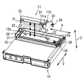
緊急通報装置を示す斜視図である。
バッテリを取り付ける前の状態を示す。
バッテリを収納空間に配置した状態を示す。
蓋を取り付ける前の状態を示す。
バッテリの取付け動作を説明するための図である。
蓋の組み付け動作を示す。
蓋の組み付け動作を示す。
緊急通報装置を拡大して示す斜視図である。
蓋の組み付け動作を示す。
バッテリの取外し動作を示す。
バッテリの取外し動作を示す。
バッテリの取外し動作を示す。
バッテリの取外し動作を示す。
ピンおよび溝を拡大して示す。
図14の切断面線XVから見て示す断面図である。
本開示の一実施形態に関して、図1から図15を用いて説明する。図1に示す車載の緊急通報装置10は、車両の衝突事故といった緊急事態発生時に、通報先である緊急通報センタに緊急通報を行うための装置である。車両用の緊急通報装置10としては、例えばDCM(Data Communication Module)等のテレマティクスサービスに用いられる通信モジュールなどがある。
緊急通報装置10は、メインバッテリおよびバックアップバッテリ11から電力が供給される。メインバッテリは、車両の各電気負荷(各電気機器)に電力を供給するメイン電源であり、エンジン始動時にはスターターに電力を供給する電源として使用することも可能である。さらに、メインバッテリは、緊急通報装置10のメイン電源でもある。例えばメインバッテリは、鉛蓄電池により構成される。なお、車両のアクセサリ(ACC)電源がオンのときにメインバッテリからの電力供給を可能としてもよい。
バックアップバッテリ11は、メインバッテリの代替電源として少なくとも緊急通報装置10に対して電力供給を行うサブ電源である。バックアップバッテリ11は、たとえば交通事故などにより、メインバッテリそのものが破損したり、メインバッテリからの電力供給ラインが断線したりすることによって、メインバッテリからの電力供給が不可能になった場合に電源として機能する。バックアップバッテリ11は、着脱可能な二次電池によって構成される。
バックアップバッテリ11としては、例えば-30℃程度から+85℃程度の温度環境下で動作可能であって、長寿命である二次電池が用いられる。バックアップバッテリ11は、たとえばリチウムイオン二次電池およびリチウムイオンポリマー二次電池が用いられる。リチウムイオン二次電池などは、水よりも融点の低い有機溶媒を用いるため低温でも使用可能である。さらにリチウムイオン二次電池などは、ニカド電池やニッケル水素充電池等の他の二次電池に比べて自己放電特性が格段によく、長寿命である。またリチウムイオン二次電池などは、小型化が可能であって搭載上の制約が小さい。なお、バックアップバッテリ11としてニッケル水素二次電池などのリチウムイオン二次電池およびリチウムイオンポリマー二次電池以外の二次電池を用いる構成であってもよい。
このようなバックアップバッテリ(以下、バッテリということがある)11は、本体ケース12に装着された後、蓋13によって覆われている。これによってバッテリ11の表面は露出せずに、本体ケース12の内部に収納される。
このような緊急通報装置10では、バッテリ11の着脱および固定に関して、製品固有の制約などがある。具体的な制約を、以下の(1)から(6)にて説明する。
(1)本体ケース12の上面にバッテリ11の開口部12aがあり、本体ケース12の上面から上方向にバッテリ11を取り外さなくてはならない。
(2)本体ケース12のサイズ制約のため、バッテリ11に上方向に持ち上げるための取手を設けることができない。したがって取手を摘まんでバッテリ11を持ち上げる取り外し方法は適用できない。
(3)バッテリ11を本体ケース12に組込んだ状態で、バッテリ11の側面から指でバッテリ11を摘まむために必要な隙間を設けることができない。したがってバッテリ11の外形を指で摘まんで、バッテリ11を上方向に持ち上げる方法は適用できない。
(4)バッテリ11を本体に組込んだ状態でバッテリ11を動かすには、直方体状のバッテリ11の4つの側面のうち、短辺の1面から、指で押す操作しかできない。したがってバッテリ11を長手方向にスライドさせることしかできない。
(5)本体ケース12に収納されているバッテリ11の周囲は、バッテリ11の収納空間12bへの水の流れ込みを防ぐために、バッテリ11より高い位置に止水リブ21を設ける必要がある。したがってバッテリ11をスライドさせるだけでは、バッテリ11を止水リブ21の高さより上に持ち上げる状態にはならない。(4)の制約によって、バッテリ11を指1本でスライドさせるだけで上下方向の拘束を解除すると共に、バッテリ11を上方向に押し上げ、そして指1本でバッテリ11を収納空間12bから起こすことができる構成が必要である。
(6)車載製品の場合、バッテリ11と本体ケース12とのガタをなくし異音を防止する必要がある。したがってバッテリ11側のピン31と本体ケース12との間には隙間がないか、摺動が可能な程度に隙間を有するように、バッテリ11を本体ケース12に軽圧入する必要がある。またバッテリ11側のピン31と本体ケース12との接触部分を面接触にすると摩擦が大きくなりバッテリ11をスライドさせることができない場合があるので、線接触が好ましい。
このような(1)から(6)の制約を考慮した緊急通報装置10におけるバッテリ11の固定装置に関して説明する。固定装置は、バッテリ11、本体ケース12および蓋13を含んでいる。図2に示すように、バッテリ11は、外形が直方体状、具体的には上面が平坦状であり、下面が半円状の長手状部品である。本体ケース12の内部には、バッテリ11を収納する収納空間12bが形成されている。図2および図3に示すように、収納空間12bは、バッテリ11が収納空間12bに収納された状態でバッテリ11の周囲に隙間が形成されないか、または小さな隙間が形成される形状を有している。また蓋13は、図1および図4に示すように、収納空間12bにバッテリ11が収納されている状態で、本体ケース12と接触して収納空間12bを覆う。
ここで直方体状のバッテリ11が延びている方向を、長手方向Xと称する。長手方向Xのうち、バッテリ11を装着する方向が取付方向X1であり、バッテリ11を外す方向が取外し方向X2である。したがって取付方向X1と取外し方向X2とは、反対方向である。また長手方向Xと交差、本実施形態では直交する方向であって、バッテリ11を装着および外す方向を上下方向Zと称する。上下方向Zのうち、バッテリ11を収納空間12bに取り付けるときの方向が下方向Z1であり、収納空間12bから取り外す方向が上方向Z2である。したがって下方向Z1と上方向Z2とは、反対方向である。上下方向Zおよび長手方向Xと直交する方向は、幅方向Yと称する。
図5に示すように、バッテリ11には、突起としてピン31が形成されている。そして本体ケース12には、ピン31が係合する溝22が形成されている。ピン31は、バッテリ11の側面であって、長手方向Xに延びる側面に複数、本実施形態では4つ、長手方向Xに間隔をあけて形成されている。ピン31は、各側面に2個ずつ形成されている。ピン31は、外形が円柱状であり、溝22と線接触するように構成されている。
バッテリ11には、取付方向X1側の端部にコード33が設けられている。コード33の先端には、コネクタ34が接続されている。コネクタ34は、本体ケース12に設けられる接続部30に接続されると、バッテリ11から緊急通報装置10に電力供給が可能となる。
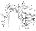
収納空間12bを形成する側壁23には、複数の溝22が長手方向Xに間隔をあけて形成されている。本実施形態では、4つの溝22が形成されており、対向する2つの側壁23のそれぞれが、2つの溝22を有している。溝22は、図5および図8に示すように、下方向Z1に延びる収納部分24と、傾斜方向に延びる傾斜部分25と、長手方向Xに延びる設置部分26とを有する。したがって溝22は、側面から見てL字状である。
溝22のうち収納部分24は、上方向Z2に広く開放されており、下方向Z1に進むにつれて間隔が狭くなるように形成されている。換言すると、溝22の入口には、ピン31と干渉しないように逃がし形状を形成している。これによってピン31を溝22の入口に導きやすく、またピン31を溝22の奥の方に容易に導くことができる。
溝22のうち傾斜部分25は、収納部分24における下方の端部から、下方向Z1に進むにつれて取付方向X1に進むように延びている。換言すれば、傾斜部分25は、収納部分24の下方の端部と傾斜部分25との取付方向(交差方向)X1の距離が、下方向(収納方向)Z1に向けて短くなるように延びている。つまり、傾斜部分25は、収納部分24の下方の端部と傾斜部分25との間の長手方向Xの距離が、上方向Z2に向かって長くなるように延びている。傾斜部分25が延びる方向を傾斜方向とする。傾斜部分25は、収納部分24と設置部分26とを繋いでいる。
溝22のうち設置部分26は、傾斜部分25における傾斜方向の端部から取付方向X1に延びる。設置部分26のうち、少なくとも固定状態にてピン31が配置される部分は、上下方向Zの間隔がピン31の外形と同じか軽圧入が可能な寸法に設定される。
取付方向X1側の2つの溝22の形状と、取外し方向X2側の2つの溝22の形状は互いに異なっている。取外し方向X2側の2つの溝22には、段差部27が形成されている。段差部27は、収納部分24の一部に形成されており、長手方向Xに延びる平面27aと取外し方向X2への変位を規制する規制面27bとを有する。段差部27の平面27aには、ピン31が載置することができる長さを有する。
取外し方向X2側の2つの溝22は、段差部27が形成されているので、収納部分24の長手方向Xの間隔が広がっている。これに対して、取付方向X1側の2つの溝22の収納部分24における長手方向Xの間隔は、ピン31の外形よりもやや大きく設定されている。換言すると、取付方向X1側の上下方向Zに延びる収納部分24は、ピン31がぎりぎり通過できる程度に間隔を狭く設定している。
またバッテリ11のうち、取外し方向X2側の側面であって、上下方向Zおよび幅方向Yを含む側面には、凸部32が形成されている。凸部32は、図5に示すように、当該側面の上方向Z2側の端部に形成されており、取外し方向X2に突出している。
そして図12の(d)の配置状態で示すように、本体ケース12には、支持部となる止水リブ21が形成されている。段差部27の平面27aにピン31が配置されている状態では、図12に示すように、凸部32が止水リブ21の上方向Z2に位置している。換言すると、バッテリ11の上部に1箇所、止水リブ21とオーバーラップする形で凸部32が形成されている。
溝22の傾斜部分25は、凸部32が止水リブ21の直ぐ上に引っかかる状態で位置し、かつバッテリ11が水平姿勢の状態のとき、すなわち図12の(e)の状態のとき、ピン31が位置する場所から傾斜部分25の起点が形成されている。そしてバッテリ11を取り外すために、取付方向X1側の側面を上方向Z2に変位させる場合、凸部32と止水リブ21とが接触して支点となる。
蓋13は、図4に示すように、板状であって、取付方向X1側の端部に係合爪41を有し、取外し方向X2側の端部にスナップフィット部42を有する。本体ケース12の蓋13によって覆われる部分のうち、取付方向X1側の端部には、係合爪41に係合する係合凹部28を有する。また本体ケース12の蓋13によって覆われる部分のうち、取外し方向X2側の端部には、スナップフィット部42が係合する受け部29を有する。
係合爪41は、上下方向Zに対して傾斜する斜め方向から係合凹部28に挿入可能であり、挿入された状態で、上下方向Zへの変位が規制されている。係合爪41を係合凹部28に挿入した状態で、係合爪41側を支点として、蓋13を下方向Z1に回転させると、スナップフィット部42が受け部29に係合する。
スナップフィット部42は、図6および図7に示すように、断面が略U字状に形成されており、弾性変形可能に構成されている。受け部29は、スナップフィット部42が弾性変形した状態で支持するように形状が選択されている。これによってスナップフィット部42を受け部29に挿入すると、スナップフィット部42は弾性変形して受け部29に挿入されて、スナップフィット部42の弾性力によって受け部29に固定される。
スナップフィット部42には、取外し方向X2に突出する蓋用爪43が形成されている。また受け部29には、蓋用爪43が挿通する挿通孔29aが形成されている。スナップフィット部42が受け部29に固定された状態では、蓋用爪43が挿通孔29aの内部に配置される。これによってスナップフィット部42の長手方向Xの間隔が小さくなるように弾性変形させないと、蓋用爪43が挿通孔29aから抜けない。したがってスナップフィット部42が受け部29に固定されている状態では、上下方向Zの変位が蓋用爪43および挿通孔29aによって規制されている。
収納空間12bの周囲には、上方向Z2に延びる止水リブ21が形成されている。止水リブ21は、下方向Z1に見て、収納空間12bを囲うように配置されている。図3に示すように、バッテリ11が収納空間12bに配置された状態では、止水リブ21における上方の端部はバッテリ11の上面よりも上方に位置する。また蓋13の下面には、止水リブ21に嵌合する止水溝45が形成されている。蓋13を装着すると、止水リブ21が止水溝45に嵌合し、防水性が確保される。
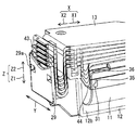
また蓋13には、図7および図8に示すように、収納空間12bを覆っている状態でバッテリ11と接触する規制部44を有する。規制部44は、蓋13の下面に下方向Z1に突出するように形成されている。また規制部44は、幅方向Yに間隔をあけて2つ設けられている。規制部44は、長手方向Xおよび上下方向Zに延びる表面を有する板状に形成されている。規制部44は、下方向Z1に向かうにつれて、長手方向Xの寸法が小さくなる先細り形状である。規制部44の先端は、たとえば円弧状に形成される。規制部44は、前述のように蓋13を下方向Z1に回転させると、先端がバッテリ11の取外し方向X2側の端部36に接触し、バッテリ11を取付方向X1側にスライド変位するように押圧することができる。
またバッテリ11には規制部44が接触する端部36は、側面に見て、R面取りが施されている。これによって規制部44が接触しても、バッテリ11に引っかかることなく、円滑に取付方向X1に押圧される。したがって本体ケース12内にバッテリ11が固定された固定状態では、ピン31が設置部分26に係合している。規制部44は、本体ケース12に対して取外し方向X2へのバッテリ11の変位を規制している。
また蓋13には,図8に示すように、収納空間12bを覆っている状態で本体ケース12に接触する三角リブ46を有する。三角リブ46は、蓋13の取外し方向X2側に突出し、上下方向Zに延びるように形成されている。三角リブ46は、取外し方向X2側に向かうにつれて幅方向Yの寸法が小さくなるように先細り形状に形成されている。具体的には、三角リブ46を上下方向Zに見た断面形状は、三角状である。また三角リブ46は、幅方向Yに間隔をあけて2つ設けられている。本体ケース12に蓋13が取り付けられた状態では、三角リブ46は、本体ケース12の内壁に線接触している。
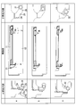
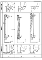
次に、固定する際の動作に関して、図9に示すように段階的に説明する。バッテリ11を固定する際は、まず図2に示すように、収納空間12bの上方向Z2からバッテリ11を収納方向である下方向Z1に変位させる。するとピン31が、図5に示すように、溝22の収納部分24を通過し、傾斜部分25に配置される。すると、ピン31はバッテリ11の自重によって傾斜部分25を滑り、設置部分26の取外し方向X2側に配置される。換言すると、バッテリ11を溝22に落とし込むだけで、バッテリ11は重力に従い溝22の奥(底部)の設置部分26の入口まで配置される。またこの状態で、図3に示すように、コネクタ34が接続部30に接続される。このような状態から、図5に示すように、次の段階としてバッテリ11を取付方向X1に変位させる必要がある。
そこで図9に段階的に示すように、蓋13の係合爪41と本体ケース12の係合凹部28に挿入して、蓋13を下方向Z1に回転させる。するとスナップフィット部42が受け部29に弾性変形しながら進入すると同時に、図9の(c)の配置状態で、規制部44の先端がバッテリ11に接触する。そしてそのまま蓋13を下方向Z1に回転させると、規制部44によってバッテリ11が押されて、ピン31が溝22の設置部分26に沿って変位し、ピン31が設置部分26の最も奥側(取付方向X1における端部側)の位置に配置される。
さらにこの状態で、スナップフィット部42が受け部29に固定される。したがって規制部44もバッテリ11を取付方向X1に押圧した状態で固定される。これによってバッテリ11は、取外し方向X2への変位が規制部44によって規制される。またバッテリ11の上下方向Zの変位は、設置部分26によって規制される。そして図1に示すように、蓋13によって収納空間12bも覆われる。
次に、バッテリ11を取り外す際の動作に関して、図10から図13を用いて説明する。バッテリ11を取り外す際には、先ず蓋13を取り外す。蓋13を取り外すためには、スナップフィット部42を弾性変形させて、係合爪41と挿通孔29aから離脱させる。すると蓋13の固定が解除されるので、蓋13を取り外すことができる。
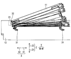
次に、バッテリ11の取付方向X1側の側面11aを、図3に示すように、取外し方向X2側に押圧する。すると、図10に示すように、蓋13の規制部44がないので、ピン31が溝22の設置部分26を取外し方向X2側に変位し、段差部27の平面27aにピン31が配置される。平面27aにピン31が配置されている状態では、取付方向X1側のピン31は、図12の(d)に示すように、溝22の収納部分24に配置されている。したがって取付方向X1のピン31は、取外し方向X2にスライドされて上下方向Zの拘束が解除されているので、バッテリ11の取付方向X1側の端部11bを上方向Z2に持ち上げることができる。換言すると、段差部27にピン31を配置することで、取付方向X1のピン31が位置決めされて、持ち上げる軌跡を描くことができる。そしてバッテリ11の取付方向X1側の端部11bを上方向Z2に持ち上げると、取外し方向X2側の止水リブ21の先端と凸部32とが支点となって、図10に示すように回転させることができ、バッテリ11を取り外すことができる。
図11にて取り外す動作を段階的に説明すると、固定状態において、蓋13を外した状態では、図11の(a)に示すように、ピン31が溝22の設置部分26に圧入されている状態にある。そこで図11の(b)および(c)のようにバッテリ11の側面11aを取外し方向X2に押圧して、取外し方向X2側にスライド変位させると、図12の(d)のようにピン31が段差部27に配置される。したがって作業者が指先などをつかってバッテリ11を取外し方向X2に押すだけで、ピン31が傾斜部分25に沿って変位して、段差部27の規制面27bに突き当たる。ピン31が段差部27の平面27aに配置されることで、ピン31を安定して保持することができる。また段差部27にピン31が配置された状態では、止水リブ21と凸部32とが上下方向Zに近接している。
次に、取付方向X1側の端部11bを図12の(e)のように持ち上げると、止水リブ21の先端に凸部32が引っかかって、支点となって、回転させることができる。これによって取付方向X1側に位置するピン31が溝22から徐々に図12の(f)のように離脱する。
さらに回転させて、図13の(g)、(h)、(i)のように変位して、バッテリ11の取付方向X1側の端部11bが収納空間12bから離脱するので、この状態になると、作業者はバッテリ11の全体を指でつかんで、取り外すことができる。
またピン31が形成されている側面には、図14に示すように、ピン31に近接した位置に突出部35が形成されている。突出部35は、図15に示すように、ピン31と同様に、長手方向Xに間隔をあけて、バッテリ11の対向する2つの側面のそれぞれに2個ずつ形成されている。突出部35は、側面から外側に突出するように形成されている。また突出部35は、ピン31から上方向Z2に延びるように形成されている。さらに突出部35は、図15に示すように、下方に見て断面が半円状に形成されている。したがって突出部35の取付方向X1側の表面は、取外し方向X2に進むにつれて、突出量が大きくなるように形成されている。また半円状であるので、突出部35と側壁23とは線接触となる。
そして、図11の(c)に示すように、ピン31が収納部分24と係合している状態では、突出部35は収納部分24に対向した位置にあり、溝22が形成されている側壁23に接触していない。また図11の(a)に示すように、ピン31が設置部分26に係合している固定状態では、突出部35は溝22が形成されている収納空間12bの側壁23に接触している。
また側壁23には、図15に示すように、テーパ23aが形成されている。テーパ23aは、溝22の取付方向X1側であって、取付方向X1に進むにつれて、収納空間12bの幅方向Yの間隔が小さくなるように傾斜している。これによってバッテリ11を取り付ける際に、取付方向X1にバッテリ11が変位すると、突出部35がバッテリ11の側面と収納空間12bの側壁23との隙間を埋めるように進入する。また突出部35の先端は円弧状であるので、突出部35の先端と側壁23とは線接触となる。これによって突出部35が側壁23と線接触しながら円滑に取付方向X1に移動し、バッテリ11が収納空間12bに軽圧入される。この結果、固定状態では、突出部35の先端が側壁23に接触しているので、バッテリ11の幅方向Yの変位を抑制することができる。
以上説明したように、本実施形態の固定装置は、本体ケース12内にバッテリ11が固定された固定状態では、ピン31が設置部分26に係合している。これによってピン31が上下方向Zへ変位することが規制されている。さらに固定状態では、バッテリ11は、本体ケース12に対して取外し方向X2への変位が蓋13の規制部44によって規制されている。これによって上下方向Zおよび長手方向Xへの変位が規制されるので、確実にバッテリ11を収納空間12bに固定することができる。
またバッテリ11を固定する場合には、まず、溝22の収納部分24とピン31とが係合するように、収納空間12bにおけるバッテリ11の位置を調整する。蓋13を配置すると、蓋13の規制部44によってバッテリ11が押されて、取付方向X1(交差方向)に延びる設置部分26にピン31が係合する。したがってバッテリ11を収納空間12bに配置し、蓋13をするだけで、バッテリ11を固定することができる。これによって簡単な操作でバッテリ11を固定することができる。またバッテリ11を設置部分26に配置するためのつまみや押下面などが必要ないので、固定装置を小型化することができる。
換言すると、バッテリ11の組付け時に、バッテリ11を本体ケース12の溝22に挿入するだけで、図5で矢印Iにて示すように、バッテリ11の自重(重力)によりバッテリ11が傾斜部分25の下端、すなわち設置部分26の入口まで移動する。そして、蓋13を閉めるだけで、バッテリ11が取付方向X1に押されて、図5で矢印IIにて示すように、所定の固定位置に移動する。これにより、バッテリ11の組付け時は、バッテリ11を溝22内に挿入し、本体ケース12に蓋13を取り付けるという2段階でバッテリ11の組付けと蓋13の組付けを行うことができる。また取り外し時は、指1本でバッテリ11を浮かせて、取り外すことができる。さらにバッテリ11は周囲を固定されているので、衝撃に伴うバッテリ11の飛び出しと、バッテリ11のガタツキによる異音の発生の双方を防止できる。
具体的には、ピン31が設置部分26に圧入されているので、上下方向Zの衝撃によりバッテリ11が離脱することを防ぐことができる。設置部分26の奥(取付方向X1の端部)の閉塞によってピン31の取付方向X1の移動が規制され、取外し方向X2は規制部44によって規制されている。したがって、長手方向Xの衝撃によりバッテリ11が離脱することを防ぐことができる。また幅方向Yの振動は、突出部35と側壁23によって変位が規制されているので、バッテリ11の離脱を防ぐことができる。
さらに蓋13は、スナップフィット部42が受け部29に弾性力によって固定されているので、蓋13が上下方向Zの衝撃によって外れることをスナップフィット部42の弾性力によって抑制している。さらに蓋13は、止水リブ21と止水溝45とが嵌合しているので、幅方向Yおよび長手方向Xの変位が規制されている。したがって蓋13が衝撃によって外れることを抑制している。
また本実施形態では、前述の(1)から(6)の制約を満たしている。具体的には、固定装置は、(1)の制約である本体ケース12の上面にバッテリ11の開口部12aがあり、本体ケース12の上面から上方向Z2にバッテリ11を取り外す構成である。
また固定装置は、(2)の制約のとおり、つまみなどが不要な構成である。さらに固定装置は、(3)の制約のとおり、バッテリ11の側面に指が入るような隙間がない構成である。
また固定装置は、(4)の制約のとおり、固定状態から取外し方向X2にだけ押圧によって変位させることができる。これによって取り外すことができる。また固定装置は、(5)の制約のとおり、止水リブ21が設けられているが、バッテリ11の凸部32を止水リブ21に引っかけて回転させることによって、バッテリ11を持ち上げることができる。
さらに固定装置は、(6)の制約のとおり、ピン31は円柱状であるので、溝22とピン31とが線接触する構成である。これによって摩擦を小さくすることができ、バッテリ11の取付および取外しを円滑に行うことができる。
さらに本実施形態では、溝22が傾斜部分25を有する。溝22の収納部分24にピン31を配置することによって、バッテリ11の重力によってピン31を設置部分26の入口まで傾斜部分25に沿って変位させることができる。これによって設置部分26の入口へのピン31の位置決めを容易にすることができる。
また本実施形態では、収納部分24には、段差部27が形成されている。そしてバッテリ11には、凸部32が形成されており、固定状態では凸部32は上下方向Zにおいて止水リブ21の先端と近接した位置で止水リブ21と対向している。これによってバッテリ11を取り外すときに、ピン31を段差部27の平面27aの安定した位置に配置し、そこから回転させることによって、凸部32が止水リブ21に引っかかって回転の支点にすることができる。これによって回転が容易となり、バッテリ11の取外し作業を容易にすることができる。
さらに本実施形態では、バッテリ11の側面には、突出部35が形成されている。突出部35は、固定状態では、収納空間12bを形成する側壁23に接触する。これによって突出部35は、収納空間12bの側壁23とバッテリ11の側面との隙間を埋めることができる。したがって幅方向Yの変位を規制することができる。また突出部35は、ピン31が溝22の収納部分24にあるときは、収納空間12bの側壁23とは離間した位置となるように、突出部35が形成される位置が選択されている。これによってバッテリ11が固定状態となる前に突出部35が側壁23と接触して、バッテリ11の取付および取外し操作の妨げになることを抑制することができる。
(その他の実施形態)
以上、本開示の好ましい実施形態について説明したが、本開示は上述した実施形態に何ら制限されることなく、本開示の主旨を逸脱しない範囲において種々変形して実施することが可能である。
以上、本開示の好ましい実施形態について説明したが、本開示は上述した実施形態に何ら制限されることなく、本開示の主旨を逸脱しない範囲において種々変形して実施することが可能である。
上述した実施形態の構造は、あくまで例示であって、本開示の範囲はこれらの記載の範囲に限定されるものではない。本開示の範囲は、本開示の記載の均等の意味及び範囲内での全ての変更を含むものである。
上述した実施形態では、ピン31は、円柱状であったが、円柱状に限るものではなく、他の形状、たとえば多角形状であってもよく、円錐状および多角錘状であってもよい。またピン31および溝22の数は、4つであったが、4つに限るものではなく、少なくとも1つあればよい。
上述した実施形態では、ピン31はバッテリ11に形成され、溝22が収納空間12bの側壁23に形成されているが、このような構成に限るものではない。バッテリ11と側壁23のいずれか一方にピン31が形成され、バッテリ11と側壁23のいずれか他方に溝22が形成されていればよい。したがってバッテリ11に溝22を形成し、ピン31を収納空間12bの側壁23に形成してもよい。
上述した実施形態では、溝22は傾斜部分25を有する構成であるが、傾斜部分25を有さない形状、すなわち溝22が収納部分24と設置部分26とが直交する形状であってもよい。このような溝22の場合は、設置部分26が収納部分24における下方の端部から取付方向X1に延びる。
上述した実施形態では、バッテリ11を緊急通報装置10に固定する固定装置であったが、緊急通報装置10の本体ケース12およびバッテリ11に限るものではなく、対象物を本体ケース内に固定する構造であればよい。したがって、たとえば対象物は、回路基板などの電子装置であってもよく、ギヤボックスなどの機械的部品であってもよい。
Claims (6)
- 本体ケース(12)内に対象物(11)を固定する固定装置であって、
前記対象物を収納する収納空間(12b)が内部に形成されている前記本体ケースと、
前記収納空間に収納される前記対象物と、
前記収納空間に前記対象物が収納されている状態で、前記本体ケースと接触して前記収納空間を覆う蓋(13)と、含み、
前記本体ケースには、突起(31)および前記突起が係合する溝(22)のいずれか一方が形成されており、
前記対象物には、前記突起および前記溝のいずれか他方が形成されており、
前記溝は、
前記対象物を前記収納空間に収納する収納方向(Z1)に延びる収納部分(24)と、
前記収納方向に交差する交差方向(X1)に延びる設置部分(26)と、を有し、
前記設置部分は、前記収納部分における前記収納方向の端部から前記交差方向に延び、
前記蓋は、前記収納空間を覆っている状態で前記対象物と接触する規制部(44)を有し、
前記本体ケース内に前記対象物が固定された固定状態では、前記突起が前記設置部分に係合しており、
前記対象物は、前記本体ケースに対して前記交差方向とは反対方向への変位が前記規制部によって規制されている固定装置。 - 前記収納部分は、傾斜部分(25)を有し、
前記傾斜部分は、前記収納方向に延びる前記収納部分の端部から、前記収納方向に進むにつれて前記交差方向に進むように傾斜する傾斜方向に延び、
前記設置部分は、前記傾斜部分における前記傾斜方向の端部から前記交差方向に延びる請求項1に記載の固定装置。 - 前記収納空間を形成する側壁(23)には、複数の前記溝が前記交差方向に間隔をあけて形成されており、
前記対象物の側面であって、前記収納方向および前記交差方向に延びる側面には、複数の前記突起が前記交差方向に間隔をあけて形成されており、
前記収納部分の一部には、前記交差方向に延びる平面(27a)と前記交差方向とは反対方向への変位を規制する規制面(27b)とを有する段差部(27)が形成されており、
前記対象物には、前記交差方向に交差する側面に凸部(32)が形成されており、
前記本体ケースには、前記収納方向とは反対方向に支持部(21)が形成されており、
前記段差部の前記平面に前記突起が配置されている状態では、
前記凸部が前記支持部の前記収納方向とは反対方向に位置しており、
前記凸部が形成されている側面とは反対側の側面を前記収納空間から前記収納方向とは反対方向に変位させる場合、前記凸部と前記支持部とが接触して支点となる請求項1または2に記載の固定装置。 - 前記収納空間を形成する側壁には、複数の前記溝が前記交差方向に間隔をあけて形成されており、
前記対象物の側面であって、前記収納方向および前記交差方向に延びる側面には、複数の前記突起が前記交差方向に間隔をあけて形成されており、
前記突起が形成された前記対象物の側面は突出部(35)を有し、
前記突出部は、
前記交差方向とは反対方向に進むにつれて、突出量が大きくなるように形成されており、
前記突起が前記収納部分と係合している状態では、前記収納部分に対向した位置あり、前記溝が形成されている側壁に接触しておらず、
前記固定状態では、前記収納空間の前記溝が形成されている側壁に接触している請求項1ないし3のいずれか1つに記載の固定装置。 - 前記突起は、円柱状である請求項1ないし4のいずれか1つに記載の固定装置。
- 対象物(11)を内部に固定する固定装置であって、
本体ケース(12)と、
前記本体ケースの内部に形成されて、前記対象物を収納する収納空間(12b)と、
前記収納空間に前記対象物が収納されている状態で、前記本体ケースと接触して前記収納空間を覆う蓋(13)と、含み、
前記本体ケースには、突起(31)および前記突起が係合する溝(22)のうち一方が形成されており、
前記対象物には、前記突起および前記溝のうち他方が形成されており、
前記溝は、
前記対象物を前記収納空間に収納する収納方向(Z1)に延びる収納部分(24)と、
前記収納方向に交差する交差方向(X1)に延びる設置部分(26)と、を有し、
前記設置部分は、前記収納部分における前記収納方向の端部から前記交差方向に延び、
前記蓋は、前記収納空間を覆っている状態で前記対象物と接触する規制部(44)を有し、
前記本体ケース内に前記対象物が固定された固定状態では、前記突起が前記設置部分に係合しており、
前記規制部は、前記本体ケースに対して前記交差方向とは反対方向への前記対象物の変位を規制する固定装置。
Priority Applications (3)
| Application Number | Priority Date | Filing Date | Title |
|---|---|---|---|
| US15/765,497 US10396324B2 (en) | 2015-10-05 | 2016-09-05 | Fixing device |
| CA2997411A CA2997411C (en) | 2015-10-05 | 2016-09-05 | Fixing device |
| DE112016004543.3T DE112016004543B4 (de) | 2015-10-05 | 2016-09-05 | Festlegungsvorrichtung |
Applications Claiming Priority (2)
| Application Number | Priority Date | Filing Date | Title |
|---|---|---|---|
| JP2015197774A JP6361623B2 (ja) | 2015-10-05 | 2015-10-05 | 固定装置 |
| JP2015-197774 | 2015-10-05 |
Publications (1)
| Publication Number | Publication Date |
|---|---|
| WO2017061202A1 true WO2017061202A1 (ja) | 2017-04-13 |
Family
ID=58487449
Family Applications (1)
| Application Number | Title | Priority Date | Filing Date |
|---|---|---|---|
| PCT/JP2016/075932 Ceased WO2017061202A1 (ja) | 2015-10-05 | 2016-09-05 | 固定装置 |
Country Status (5)
| Country | Link |
|---|---|
| US (1) | US10396324B2 (ja) |
| JP (1) | JP6361623B2 (ja) |
| CA (1) | CA2997411C (ja) |
| DE (1) | DE112016004543B4 (ja) |
| WO (1) | WO2017061202A1 (ja) |
Cited By (1)
| Publication number | Priority date | Publication date | Assignee | Title |
|---|---|---|---|---|
| CN109346635A (zh) * | 2018-09-29 | 2019-02-15 | 湖北华中光电科技有限公司 | 可快速拆装、锁紧、密封功能的电池盒装置及其使用方法 |
Families Citing this family (2)
| Publication number | Priority date | Publication date | Assignee | Title |
|---|---|---|---|---|
| JP6965820B2 (ja) * | 2018-04-23 | 2021-11-10 | トヨタ自動車株式会社 | 蓄電装置の搭載構造 |
| JP7139071B2 (ja) * | 2019-06-28 | 2022-09-20 | ダイハツ工業株式会社 | 車載用制御装置 |
Citations (3)
| Publication number | Priority date | Publication date | Assignee | Title |
|---|---|---|---|---|
| JPH08298104A (ja) * | 1995-04-27 | 1996-11-12 | Sony Corp | バッテリーパック |
| JPH08315863A (ja) * | 1995-05-17 | 1996-11-29 | Sanyo Electric Co Ltd | パック電池を電気機器に装着するアタッチメント |
| JP2006156348A (ja) * | 2005-10-04 | 2006-06-15 | Sony Computer Entertainment Inc | バッテリパックおよびこれを用いた電子機器 |
Family Cites Families (11)
| Publication number | Priority date | Publication date | Assignee | Title |
|---|---|---|---|---|
| JPH0737563A (ja) | 1993-07-22 | 1995-02-07 | Sony Corp | 機器用乾電池パック |
| JPH08162077A (ja) | 1994-12-01 | 1996-06-21 | Matsushita Electric Ind Co Ltd | 電池パック装置及びその装着方法 |
| JPH1040892A (ja) * | 1996-07-19 | 1998-02-13 | Omron Corp | 電子機器の電池収納ユニット |
| JP3667982B2 (ja) | 1998-03-19 | 2005-07-06 | Smk株式会社 | 小型電子機器の着脱装置 |
| WO2007072660A1 (ja) * | 2005-12-21 | 2007-06-28 | Nec Corporation | ケース入りフィルム外装電気デバイス |
| CN101873777B (zh) * | 2009-04-27 | 2014-11-05 | 鸿富锦精密工业(深圳)有限公司 | 机箱 |
| CN103201874B (zh) * | 2010-10-29 | 2016-02-17 | 日本电气株式会社 | 电池组锁定结构和电子设备 |
| US8716598B2 (en) * | 2012-08-23 | 2014-05-06 | Octo Products LLC | Case for housing and protecting an electronic device |
| WO2014053926A1 (en) * | 2012-10-02 | 2014-04-10 | Koninklijke Philips N.V. | Housing with releasable locking element |
| JP2015015579A (ja) | 2013-07-04 | 2015-01-22 | Necカシオモバイルコミュニケーションズ株式会社 | 電子機器 |
| JP6351338B2 (ja) | 2014-04-01 | 2018-07-04 | 日本無線株式会社 | 航行情報送信装置および航行情報判別装置 |
-
2015
- 2015-10-05 JP JP2015197774A patent/JP6361623B2/ja active Active
-
2016
- 2016-09-05 CA CA2997411A patent/CA2997411C/en active Active
- 2016-09-05 US US15/765,497 patent/US10396324B2/en active Active
- 2016-09-05 WO PCT/JP2016/075932 patent/WO2017061202A1/ja not_active Ceased
- 2016-09-05 DE DE112016004543.3T patent/DE112016004543B4/de active Active
Patent Citations (3)
| Publication number | Priority date | Publication date | Assignee | Title |
|---|---|---|---|---|
| JPH08298104A (ja) * | 1995-04-27 | 1996-11-12 | Sony Corp | バッテリーパック |
| JPH08315863A (ja) * | 1995-05-17 | 1996-11-29 | Sanyo Electric Co Ltd | パック電池を電気機器に装着するアタッチメント |
| JP2006156348A (ja) * | 2005-10-04 | 2006-06-15 | Sony Computer Entertainment Inc | バッテリパックおよびこれを用いた電子機器 |
Cited By (2)
| Publication number | Priority date | Publication date | Assignee | Title |
|---|---|---|---|---|
| CN109346635A (zh) * | 2018-09-29 | 2019-02-15 | 湖北华中光电科技有限公司 | 可快速拆装、锁紧、密封功能的电池盒装置及其使用方法 |
| CN109346635B (zh) * | 2018-09-29 | 2021-06-01 | 湖北华中光电科技有限公司 | 可快速拆装、锁紧、密封功能的电池盒装置及其使用方法 |
Also Published As
| Publication number | Publication date |
|---|---|
| US10396324B2 (en) | 2019-08-27 |
| CA2997411A1 (en) | 2017-04-13 |
| US20190074493A1 (en) | 2019-03-07 |
| CA2997411C (en) | 2019-11-05 |
| DE112016004543T5 (de) | 2018-06-14 |
| JP6361623B2 (ja) | 2018-07-25 |
| JP2017073219A (ja) | 2017-04-13 |
| DE112016004543B4 (de) | 2024-08-01 |
Similar Documents
| Publication | Publication Date | Title |
|---|---|---|
| US7867645B2 (en) | Latching mechanism for battery cover assembly | |
| CN103219554B (zh) | 蓄电装置 | |
| JP4812353B2 (ja) | 遮断回路組立体 | |
| US7989696B2 (en) | Housing assembly for electronic device | |
| US20150207261A1 (en) | Charge connector | |
| JP5634361B2 (ja) | 電気装置 | |
| KR101417806B1 (ko) | 전자기기의 배터리 탈착 조립체 및 이를 구비한 전자기기 | |
| JP6361623B2 (ja) | 固定装置 | |
| JP5924041B2 (ja) | 電動工具セット | |
| US20200350526A1 (en) | Battery case | |
| US8095183B2 (en) | Portable electronic device with detachable keypad module | |
| US9591779B2 (en) | Electronic apparatus capable of accommodating therein member including cable | |
| US11239673B2 (en) | Charging holder for electronic devices that contains a rotation block and a pocket | |
| JP2017134959A (ja) | プロテクタおよびバスバーモジュール | |
| JP6682255B2 (ja) | マガジン、電源装置、および、撮像装置 | |
| US20150146351A1 (en) | Electronic device | |
| JP3514662B2 (ja) | バッテリパックの着脱構造 | |
| JP2000278380A (ja) | 電話機ホルダー | |
| TW202030908A (zh) | 電池組集成 | |
| JP5180030B2 (ja) | 電池保持機構および該電池保持機構を備えた充電器 | |
| JP2013026112A (ja) | 基板の保護構造、電源装置、車両及び電装部品の組み立て方法 | |
| JP2009110749A (ja) | 携帯電子機器 | |
| JP2009201324A (ja) | 可搬型ガス警報器の充電器 | |
| WO2024128065A1 (ja) | 電気機器 | |
| JP2016082755A (ja) | 携帯端末の充電装置及び携帯端末システム |
Legal Events
| Date | Code | Title | Description |
|---|---|---|---|
| 121 | Ep: the epo has been informed by wipo that ep was designated in this application |
Ref document number: 16853356 Country of ref document: EP Kind code of ref document: A1 |
|
| ENP | Entry into the national phase |
Ref document number: 2997411 Country of ref document: CA |
|
| WWE | Wipo information: entry into national phase |
Ref document number: 112016004543 Country of ref document: DE |
|
| 122 | Ep: pct application non-entry in european phase |
Ref document number: 16853356 Country of ref document: EP Kind code of ref document: A1 |