WO2017056923A1 - 車両用内装部品およびその製造方法 - Google Patents
車両用内装部品およびその製造方法 Download PDFInfo
- Publication number
- WO2017056923A1 WO2017056923A1 PCT/JP2016/076618 JP2016076618W WO2017056923A1 WO 2017056923 A1 WO2017056923 A1 WO 2017056923A1 JP 2016076618 W JP2016076618 W JP 2016076618W WO 2017056923 A1 WO2017056923 A1 WO 2017056923A1
- Authority
- WO
- WIPO (PCT)
- Prior art keywords
- adhesive
- core material
- skin material
- skin
- vehicle
- Prior art date
Links
- 238000004519 manufacturing process Methods 0.000 title claims description 15
- 239000011162 core material Substances 0.000 claims abstract description 103
- 239000000463 material Substances 0.000 claims abstract description 78
- 239000000853 adhesive Substances 0.000 claims abstract description 71
- 230000001070 adhesive effect Effects 0.000 claims abstract description 63
- 238000000034 method Methods 0.000 claims description 15
- 239000011247 coating layer Substances 0.000 claims description 10
- 239000010410 layer Substances 0.000 claims description 9
- 230000000873 masking effect Effects 0.000 description 10
- 230000000694 effects Effects 0.000 description 5
- 238000000465 moulding Methods 0.000 description 5
- 239000002184 metal Substances 0.000 description 3
- 238000005034 decoration Methods 0.000 description 2
- 230000007547 defect Effects 0.000 description 2
- 238000002474 experimental method Methods 0.000 description 2
- 239000006260 foam Substances 0.000 description 2
- 238000010438 heat treatment Methods 0.000 description 2
- 238000012805 post-processing Methods 0.000 description 2
- 239000011347 resin Substances 0.000 description 2
- 229920005989 resin Polymers 0.000 description 2
- 238000001179 sorption measurement Methods 0.000 description 2
- 239000012790 adhesive layer Substances 0.000 description 1
- 239000011248 coating agent Substances 0.000 description 1
- 238000000576 coating method Methods 0.000 description 1
- 238000000748 compression moulding Methods 0.000 description 1
- 238000002788 crimping Methods 0.000 description 1
- 238000013461 design Methods 0.000 description 1
- 230000005764 inhibitory process Effects 0.000 description 1
- 238000012986 modification Methods 0.000 description 1
- 230000004048 modification Effects 0.000 description 1
- 230000002093 peripheral effect Effects 0.000 description 1
- 239000002356 single layer Substances 0.000 description 1
- 239000007921 spray Substances 0.000 description 1
- 238000012360 testing method Methods 0.000 description 1
- 238000013022 venting Methods 0.000 description 1
Images


Classifications
-
- B—PERFORMING OPERATIONS; TRANSPORTING
- B60—VEHICLES IN GENERAL
- B60K—ARRANGEMENT OR MOUNTING OF PROPULSION UNITS OR OF TRANSMISSIONS IN VEHICLES; ARRANGEMENT OR MOUNTING OF PLURAL DIVERSE PRIME-MOVERS IN VEHICLES; AUXILIARY DRIVES FOR VEHICLES; INSTRUMENTATION OR DASHBOARDS FOR VEHICLES; ARRANGEMENTS IN CONNECTION WITH COOLING, AIR INTAKE, GAS EXHAUST OR FUEL SUPPLY OF PROPULSION UNITS IN VEHICLES
- B60K37/00—Dashboards
-
- B—PERFORMING OPERATIONS; TRANSPORTING
- B29—WORKING OF PLASTICS; WORKING OF SUBSTANCES IN A PLASTIC STATE IN GENERAL
- B29C—SHAPING OR JOINING OF PLASTICS; SHAPING OF MATERIAL IN A PLASTIC STATE, NOT OTHERWISE PROVIDED FOR; AFTER-TREATMENT OF THE SHAPED PRODUCTS, e.g. REPAIRING
- B29C51/00—Shaping by thermoforming, i.e. shaping sheets or sheet like preforms after heating, e.g. shaping sheets in matched moulds or by deep-drawing; Apparatus therefor
- B29C51/12—Shaping by thermoforming, i.e. shaping sheets or sheet like preforms after heating, e.g. shaping sheets in matched moulds or by deep-drawing; Apparatus therefor of articles having inserts or reinforcements
-
- B—PERFORMING OPERATIONS; TRANSPORTING
- B32—LAYERED PRODUCTS
- B32B—LAYERED PRODUCTS, i.e. PRODUCTS BUILT-UP OF STRATA OF FLAT OR NON-FLAT, e.g. CELLULAR OR HONEYCOMB, FORM
- B32B1/00—Layered products having a non-planar shape
-
- B—PERFORMING OPERATIONS; TRANSPORTING
- B32—LAYERED PRODUCTS
- B32B—LAYERED PRODUCTS, i.e. PRODUCTS BUILT-UP OF STRATA OF FLAT OR NON-FLAT, e.g. CELLULAR OR HONEYCOMB, FORM
- B32B27/00—Layered products comprising a layer of synthetic resin
-
- B—PERFORMING OPERATIONS; TRANSPORTING
- B32—LAYERED PRODUCTS
- B32B—LAYERED PRODUCTS, i.e. PRODUCTS BUILT-UP OF STRATA OF FLAT OR NON-FLAT, e.g. CELLULAR OR HONEYCOMB, FORM
- B32B27/00—Layered products comprising a layer of synthetic resin
- B32B27/06—Layered products comprising a layer of synthetic resin as the main or only constituent of a layer, which is next to another layer of the same or of a different material
- B32B27/065—Layered products comprising a layer of synthetic resin as the main or only constituent of a layer, which is next to another layer of the same or of a different material of foam
-
- B—PERFORMING OPERATIONS; TRANSPORTING
- B32—LAYERED PRODUCTS
- B32B—LAYERED PRODUCTS, i.e. PRODUCTS BUILT-UP OF STRATA OF FLAT OR NON-FLAT, e.g. CELLULAR OR HONEYCOMB, FORM
- B32B3/00—Layered products comprising a layer with external or internal discontinuities or unevennesses, or a layer of non-planar shape; Layered products comprising a layer having particular features of form
- B32B3/02—Layered products comprising a layer with external or internal discontinuities or unevennesses, or a layer of non-planar shape; Layered products comprising a layer having particular features of form characterised by features of form at particular places, e.g. in edge regions
-
- B—PERFORMING OPERATIONS; TRANSPORTING
- B32—LAYERED PRODUCTS
- B32B—LAYERED PRODUCTS, i.e. PRODUCTS BUILT-UP OF STRATA OF FLAT OR NON-FLAT, e.g. CELLULAR OR HONEYCOMB, FORM
- B32B3/00—Layered products comprising a layer with external or internal discontinuities or unevennesses, or a layer of non-planar shape; Layered products comprising a layer having particular features of form
- B32B3/26—Layered products comprising a layer with external or internal discontinuities or unevennesses, or a layer of non-planar shape; Layered products comprising a layer having particular features of form characterised by a particular shape of the outline of the cross-section of a continuous layer; characterised by a layer with cavities or internal voids ; characterised by an apertured layer
- B32B3/266—Layered products comprising a layer with external or internal discontinuities or unevennesses, or a layer of non-planar shape; Layered products comprising a layer having particular features of form characterised by a particular shape of the outline of the cross-section of a continuous layer; characterised by a layer with cavities or internal voids ; characterised by an apertured layer characterised by an apertured layer, the apertures going through the whole thickness of the layer, e.g. expanded metal, perforated layer, slit layer regular cells B32B3/12
-
- B—PERFORMING OPERATIONS; TRANSPORTING
- B32—LAYERED PRODUCTS
- B32B—LAYERED PRODUCTS, i.e. PRODUCTS BUILT-UP OF STRATA OF FLAT OR NON-FLAT, e.g. CELLULAR OR HONEYCOMB, FORM
- B32B5/00—Layered products characterised by the non- homogeneity or physical structure, i.e. comprising a fibrous, filamentary, particulate or foam layer; Layered products characterised by having a layer differing constitutionally or physically in different parts
- B32B5/18—Layered products characterised by the non- homogeneity or physical structure, i.e. comprising a fibrous, filamentary, particulate or foam layer; Layered products characterised by having a layer differing constitutionally or physically in different parts characterised by features of a layer of foamed material
-
- B—PERFORMING OPERATIONS; TRANSPORTING
- B32—LAYERED PRODUCTS
- B32B—LAYERED PRODUCTS, i.e. PRODUCTS BUILT-UP OF STRATA OF FLAT OR NON-FLAT, e.g. CELLULAR OR HONEYCOMB, FORM
- B32B7/00—Layered products characterised by the relation between layers; Layered products characterised by the relative orientation of features between layers, or by the relative values of a measurable parameter between layers, i.e. products comprising layers having different physical, chemical or physicochemical properties; Layered products characterised by the interconnection of layers
- B32B7/04—Interconnection of layers
- B32B7/12—Interconnection of layers using interposed adhesives or interposed materials with bonding properties
-
- B—PERFORMING OPERATIONS; TRANSPORTING
- B60—VEHICLES IN GENERAL
- B60R—VEHICLES, VEHICLE FITTINGS, OR VEHICLE PARTS, NOT OTHERWISE PROVIDED FOR
- B60R13/00—Elements for body-finishing, identifying, or decorating; Arrangements or adaptations for advertising purposes
- B60R13/02—Internal Trim mouldings ; Internal Ledges; Wall liners for passenger compartments; Roof liners
- B60R13/0256—Dashboard liners
-
- B—PERFORMING OPERATIONS; TRANSPORTING
- B60—VEHICLES IN GENERAL
- B60R—VEHICLES, VEHICLE FITTINGS, OR VEHICLE PARTS, NOT OTHERWISE PROVIDED FOR
- B60R13/00—Elements for body-finishing, identifying, or decorating; Arrangements or adaptations for advertising purposes
- B60R13/02—Internal Trim mouldings ; Internal Ledges; Wall liners for passenger compartments; Roof liners
- B60R13/0262—Mid-console liners
-
- B—PERFORMING OPERATIONS; TRANSPORTING
- B29—WORKING OF PLASTICS; WORKING OF SUBSTANCES IN A PLASTIC STATE IN GENERAL
- B29C—SHAPING OR JOINING OF PLASTICS; SHAPING OF MATERIAL IN A PLASTIC STATE, NOT OTHERWISE PROVIDED FOR; AFTER-TREATMENT OF THE SHAPED PRODUCTS, e.g. REPAIRING
- B29C2791/00—Shaping characteristics in general
- B29C2791/004—Shaping under special conditions
- B29C2791/006—Using vacuum
-
- B—PERFORMING OPERATIONS; TRANSPORTING
- B29—WORKING OF PLASTICS; WORKING OF SUBSTANCES IN A PLASTIC STATE IN GENERAL
- B29C—SHAPING OR JOINING OF PLASTICS; SHAPING OF MATERIAL IN A PLASTIC STATE, NOT OTHERWISE PROVIDED FOR; AFTER-TREATMENT OF THE SHAPED PRODUCTS, e.g. REPAIRING
- B29C51/00—Shaping by thermoforming, i.e. shaping sheets or sheet like preforms after heating, e.g. shaping sheets in matched moulds or by deep-drawing; Apparatus therefor
- B29C51/10—Forming by pressure difference, e.g. vacuum
-
- B—PERFORMING OPERATIONS; TRANSPORTING
- B29—WORKING OF PLASTICS; WORKING OF SUBSTANCES IN A PLASTIC STATE IN GENERAL
- B29C—SHAPING OR JOINING OF PLASTICS; SHAPING OF MATERIAL IN A PLASTIC STATE, NOT OTHERWISE PROVIDED FOR; AFTER-TREATMENT OF THE SHAPED PRODUCTS, e.g. REPAIRING
- B29C51/00—Shaping by thermoforming, i.e. shaping sheets or sheet like preforms after heating, e.g. shaping sheets in matched moulds or by deep-drawing; Apparatus therefor
- B29C51/16—Lining or labelling
-
- B—PERFORMING OPERATIONS; TRANSPORTING
- B29—WORKING OF PLASTICS; WORKING OF SUBSTANCES IN A PLASTIC STATE IN GENERAL
- B29K—INDEXING SCHEME ASSOCIATED WITH SUBCLASSES B29B, B29C OR B29D, RELATING TO MOULDING MATERIALS OR TO MATERIALS FOR MOULDS, REINFORCEMENTS, FILLERS OR PREFORMED PARTS, e.g. INSERTS
- B29K2105/00—Condition, form or state of moulded material or of the material to be shaped
- B29K2105/0097—Glues or adhesives, e.g. hot melts or thermofusible adhesives
-
- B—PERFORMING OPERATIONS; TRANSPORTING
- B29—WORKING OF PLASTICS; WORKING OF SUBSTANCES IN A PLASTIC STATE IN GENERAL
- B29K—INDEXING SCHEME ASSOCIATED WITH SUBCLASSES B29B, B29C OR B29D, RELATING TO MOULDING MATERIALS OR TO MATERIALS FOR MOULDS, REINFORCEMENTS, FILLERS OR PREFORMED PARTS, e.g. INSERTS
- B29K2105/00—Condition, form or state of moulded material or of the material to be shaped
- B29K2105/04—Condition, form or state of moulded material or of the material to be shaped cellular or porous
-
- B—PERFORMING OPERATIONS; TRANSPORTING
- B29—WORKING OF PLASTICS; WORKING OF SUBSTANCES IN A PLASTIC STATE IN GENERAL
- B29L—INDEXING SCHEME ASSOCIATED WITH SUBCLASS B29C, RELATING TO PARTICULAR ARTICLES
- B29L2009/00—Layered products
-
- B—PERFORMING OPERATIONS; TRANSPORTING
- B29—WORKING OF PLASTICS; WORKING OF SUBSTANCES IN A PLASTIC STATE IN GENERAL
- B29L—INDEXING SCHEME ASSOCIATED WITH SUBCLASS B29C, RELATING TO PARTICULAR ARTICLES
- B29L2031/00—Other particular articles
- B29L2031/30—Vehicles, e.g. ships or aircraft, or body parts thereof
- B29L2031/3005—Body finishings
- B29L2031/3008—Instrument panels
-
- B—PERFORMING OPERATIONS; TRANSPORTING
- B32—LAYERED PRODUCTS
- B32B—LAYERED PRODUCTS, i.e. PRODUCTS BUILT-UP OF STRATA OF FLAT OR NON-FLAT, e.g. CELLULAR OR HONEYCOMB, FORM
- B32B2307/00—Properties of the layers or laminate
- B32B2307/50—Properties of the layers or laminate having particular mechanical properties
- B32B2307/544—Torsion strength; Torsion stiffness
-
- B—PERFORMING OPERATIONS; TRANSPORTING
- B32—LAYERED PRODUCTS
- B32B—LAYERED PRODUCTS, i.e. PRODUCTS BUILT-UP OF STRATA OF FLAT OR NON-FLAT, e.g. CELLULAR OR HONEYCOMB, FORM
- B32B2605/00—Vehicles
- B32B2605/003—Interior finishings
-
- B—PERFORMING OPERATIONS; TRANSPORTING
- B32—LAYERED PRODUCTS
- B32B—LAYERED PRODUCTS, i.e. PRODUCTS BUILT-UP OF STRATA OF FLAT OR NON-FLAT, e.g. CELLULAR OR HONEYCOMB, FORM
- B32B2605/00—Vehicles
- B32B2605/08—Cars
-
- B—PERFORMING OPERATIONS; TRANSPORTING
- B32—LAYERED PRODUCTS
- B32B—LAYERED PRODUCTS, i.e. PRODUCTS BUILT-UP OF STRATA OF FLAT OR NON-FLAT, e.g. CELLULAR OR HONEYCOMB, FORM
- B32B3/00—Layered products comprising a layer with external or internal discontinuities or unevennesses, or a layer of non-planar shape; Layered products comprising a layer having particular features of form
- B32B3/02—Layered products comprising a layer with external or internal discontinuities or unevennesses, or a layer of non-planar shape; Layered products comprising a layer having particular features of form characterised by features of form at particular places, e.g. in edge regions
- B32B3/06—Layered products comprising a layer with external or internal discontinuities or unevennesses, or a layer of non-planar shape; Layered products comprising a layer having particular features of form characterised by features of form at particular places, e.g. in edge regions for securing layers together; for attaching the product to another member, e.g. to a support, or to another product, e.g. groove/tongue, interlocking
Definitions
- This case relates to interior parts for vehicles and a method for manufacturing the same.
- interior parts such as instrument panels (vehicle interior parts) are installed in the front part of the vehicle interior.
- the skin material is stuck to the core material by superposing the heated skin material on the surface of the core material coated with adhesive and vacuum-adsorbing it (vacuum simultaneous crimping).
- vacuum simultaneous crimping For example, refer to Patent Document 1.
- Patent Document 1 the interior parts for vehicles and the manufacturing method thereof described in Patent Document 1 have the following problems.
- the main purpose of this case is to solve the above-mentioned problems.
- An adhesive coating layer is provided on one of the core material or the skin material, and the core material and the skin material are fixed in a state of being overlapped via the adhesive coating layer,
- the interior part for vehicles is characterized in that an adhesive non-applied portion where an adhesive is not applied partially is formed at a corner portion of the core material or skin material having the adhesive applied layer and the vicinity thereof.
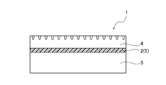
- FIG. 1 is an overall view of an interior part for a vehicle according to an embodiment. It is a side view which shows the cross-section of the vehicle interior component of FIG. It is a top view which shows the masked core material (figure which shows a masking process). It is explanatory drawing (figure which shows an adhesive agent application process) which shows the state which apply
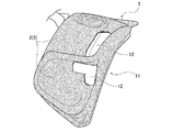
- vehicle interior parts 1 In vehicles such as automobiles, interior parts such as instrument panels (vehicle interior parts 1) as shown in FIG. 1 are installed in the front part of the vehicle interior.
- vehicle interior part 1 includes an adhesive coating layer 5 (or an adhesive layer) provided on one of the core material 3 and the skin material 4 and the core material 3 (heated).
- the skin material 4 is adhered to the core material 3 by being fixed by vacuum adsorption (vacuum simultaneous pressure molding) in a state where the skin material 4 is overlapped via the adhesive coating layer 5. .
- the vehicle interior part 1 is described as an example of an instrument panel, it is not limited to the instrument panel.
- the adhesive 2 an adhesive that is activated by heat is used.
- the said adhesive agent coating layer 5 of required thickness is formed by apply
- the core material 3 is formed of a hard resin.
- the skin material 4 is made of a soft resin.
- this embodiment has the following configuration.
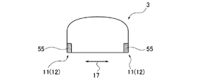
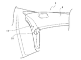
- the corner portion 11 of the core member 3 is formed at the boundary line portion between the upper surface and the front surface of the hand.
- the both side positions in the vehicle width direction 17 and the like in the boundary line portion are formed at the boundary line portion.
- the adhesive-unapplied portion 12 similar to the above may be formed not only on the corner portion 11 of the core material 3 but also on a portion where an extension or tear of the skin material 4 as will be described later is concerned. good.
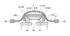
- the core material 3 has an air hole 21 at the position of the adhesive-unapplied portion 12.
- the air hole 21 is a through hole for venting air, and one or more air holes 21 may be provided with respect to the position of the adhesive non-applied portion 12 depending on the size and shape of the adhesive non-applied portion 12. it can.
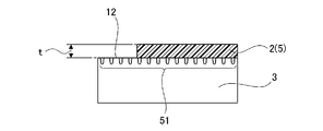
- the air holes 21 may be formed at the same time as the core material 3 is molded, or may be formed by post-processing after the core material 3 is molded and before the vacuum simultaneous press-molding. . Since the vacuum suction hole 25 is formed in the core material 3 in advance for simultaneous vacuum compression molding, the air hole 21 is preferably formed simultaneously with the vacuum suction hole 25. Alternatively, the air hole 21 may be used as a part of the vacuum suction hole 25. Further, as shown in FIG. 8, the air holes 21 are preferably provided whenever the film thickness t of the adhesive 2 (adhesive coating layer 5) is larger than about 75 ⁇ m.
- the core material 3 has fine uneven portions 31 for improving slipperiness in the adhesive-uncoated portion 12.
- the fine irregularities 31 have a large number of smooth irregularities with rounded tips.
- the depth of the unevenness of the fine unevenness portion 31 is approximately 0.3 mm or less and preferably 0.05 mm or more.
- the planar shape of the fine concavo-convex portion 31 can be the same as the concavo-convex portion for decoration 35 such as a texture pattern or a geometric pattern provided on the surface of the skin material 4 for decoration.
- the fine irregularities 31 may be provided on the entire surface of the core material 3, or may be partially provided on the surface of the core material 3 where the adhesive has not been applied 12 or its peripheral position. In this case, the fine irregularities 31 are provided on the entire surface of the core material 3.
- the fine irregularities 31 may be formed simultaneously with the molding of the core material 3, or may be formed by post-processing after the core material 3 is molded and before the vacuum simultaneous pressure-bonding molding. good.
- the skin material 4 has a multi-layer structure integrally having a foam layer 36 with poor slipperiness on the back side thereof.
- the adhesive 2 is applied to one of the core material 3 or the skin material 4 and the heated skin material 4 is superposed on the surface of the core material 3 and vacuum-adsorbed.
- the skin material 4 is adhered to the core material 3.
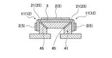
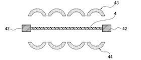
- the core material 3 to which the adhesive 2 in FIG. 5 is applied is set in a mold 41 (core material set mold) as shown in FIG.
- a mold 41 core material set mold
- both surfaces of the skin material 4 are heated by upper and lower heaters 43 and 44 while being sandwiched by clamps 42.
- the core material 3 and the skin material 4 are overlaid as shown in FIG.
- vacuum suction is performed by evacuating the metal mold
- vacuum suction holes 25 and 45 are respectively formed in advance.
- the adhesive 2 where the adhesive 2 is not applied is not applied to the corner 3 of the core material 3 or the skin material 4 applied with the adhesive 2 and the vicinity thereof.
- the portion 12 so that the core material 3 and the skin material 4 are not bonded to each other at the adhesive-uncoated portion 12, the local elongation of the skin material 4 at the adhesive-uncoated portion 12 is alleviated. The tear of the skin material 4 due to local elongation is prevented.
- the adhesive-unapplied portion 12 is formed by applying the adhesive 2 after applying the masking tape 55 to the corner portion 11 of the core material 3. Is done. As shown in FIG. 15, the masking tape 55 is peeled off after the adhesive 2 is applied.
- the tear due to local elongation of the skin material 4 does not form the adhesive non-applied portion 12, but pushes up the die 41 together with the core material 3 to bring the core material 3 into contact with the skin material 4.
- the slipperiness of the skin material 4 with respect to the core material 3 is hindered by the viscosity of the adhesive 2 applied to the core material 3.
- the one provided with the adhesive non-applied portion 12 is less likely to cause the above-described slipperiness inhibition, and as shown in FIG.
- an air hole 21 is provided at the position of the adhesive non-applied portion 12 of the core material 3 and is enclosed in the adhesive non-applied portion 12 when the core material 3 and the skin material 4 are adhered.
- the air that is to be (will be) is allowed to escape from the air holes 21.
- a fine uneven portion 31 is provided on the adhesive-unapplied portion 12 of the core material 3 so that the adhesive-applied portion 12 of the core material 3 is not applied (when the mold is pushed up or vacuumed). The slipperiness of the skin material 4 is improved.
- the interior parts manufacturing method for a vehicle first masks the corner 11 of the core material 3 with a masking jig or masking tape 55 (masking process) as shown in FIG.
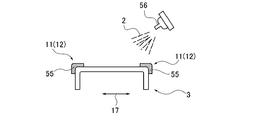
- the adhesive 2 is applied to the surface side of the core material 3
- the adhesive 2 layer is applied to the surface side of the core material 3.
- the layer 5) and the adhesive-unapplied portion 12 where the adhesive 2 is not applied are formed by masking.
- the adhesive 2 is sprayed onto the entire surface of the core material 3 using a spray nozzle 56 or the like.
- the adhesive-unapplied portion 12 is naturally formed by attaching a masking tape 55 to the surface of the core material 3 or attaching a mask member.
- the air holes 21 and the fine irregularities 31 are provided before the adhesive application step.
- the core material 3 is set in the mold 41 as shown in FIG. Further, in the skin heating process, as shown in FIG. 10, the skin material 4 sandwiched between the clamps 42 is heated by heaters 43 and 44 from above and below. Then, in the mold push-up step, as shown in FIG. 11, the heated skin material 4 is disposed above the core material 3 set in the mold 41, and the core material 3 is covered with the mold 41. Push up to material 4.
- the skin material 4 is vacuum-sucked into the core material 3 through the mold 41 and the core material 3 as shown in FIG.
- the skin material 4 is stuck on the core material 3, and the vehicle interior component 1 is molded.
- the vehicle interior part 1 has an adhesive coating layer 5 provided on one of the core material 3 and the skin material 4, and the core material 3 and the (heated) skin material 4, It is manufactured by being fixed by vacuum suction in a state of being overlapped (the skin material 4 is stuck to the core material 3).
- an adhesive-unapplied portion 12 to which the adhesive 2 was not partially applied was formed on the corner portion 11 of the core material 3 and the vicinity thereof. This prevents the core material 3 and the skin material 4 from being bonded to each other at the adhesive-unapplied portion 12 around the corner 11 of the core material 3 when the core material 3 and the skin material 4 are adhered.
- the local elongation of the skin material 4 in the adhesive-unapplied portion 12 can be relaxed, and the occurrence of tearing due to the local elongation of the skin material 4 can be prevented.
- the thickness of the skin material 4 that easily breaks was generally less than 1.5 mm. Therefore, when the skin material 4 having a thickness of less than 1.5 mm is used, it is preferable that the skin material 4 is adhered after the adhesive uncoated portion 12 is formed on the core material 3. Even in the case of the skin material 4 having a thickness of 1.5 mm or more, tearing may occur depending on the shape of the corner portion 11, and in this case, the adhesive-uncoated portion 12 is formed. Is desirable.
- the air holes 21 may be provided only when the film thickness t of the adhesive 2 is large.
- a fine uneven portion 31 was provided on the adhesive-uncoated portion 12 of the core material 3.
- the fine uneven portion 31 reduces the contact area between the adhesive-uncoated portion 12 and the skin material 4 (for example, a state close to point contact), so the adhesive-uncoated portion 12 and the skin material 4 The frictional resistance between the two is reduced, and the slipperiness can be improved accordingly. This is particularly effective in the case where the skin material 4 has a multilayer structure in which the back surface side has a foam layer 36 with poor slipperiness.
Landscapes
- Engineering & Computer Science (AREA)
- Mechanical Engineering (AREA)
- Chemical & Material Sciences (AREA)
- Combustion & Propulsion (AREA)
- Transportation (AREA)
- Vehicle Interior And Exterior Ornaments, Soundproofing, And Insulation (AREA)
- Instrument Panels (AREA)
- Laminated Bodies (AREA)
- Vehicle Step Arrangements And Article Storage (AREA)
Abstract
芯材に表皮材を貼着して成る車両用内装部品における角部の破れを防止し得るようにする。 芯材(3)または表皮材(4)の一方に接着剤塗布層(5)が設けられていると共に、芯材(3)と表皮材(4)とが、接着剤塗布層(5)を介して重ね合わせた状態で固定されている車両用内装部品(1)に関する。 上記芯材(3)の角部(11)およびその近傍に対して、部分的に接着剤(2)が塗布されない接着剤未塗布部(12)が形成されるようにしている。
Description
本件は、車両用内装部品およびその製造方法に関するものである。
自動車などの車両には、車室内の前部にインストルメントパネルなどの内装部品(車両用内装部品)が設置されている。このような内装部品には、接着剤が塗布された芯材の表面に、加熱された表皮材を重ね合わせて真空吸着することにより(真空同時圧着成形)、芯材に表皮材が貼着されて成るものが存在している(例えば、特許文献1参照)。
しかしながら、上記特許文献1に記載された車両用内装部品およびその製造方法には、以下のような問題があった。
即ち、芯材の表面に表皮材を真空吸着する際に、表皮材における、芯材の角部と接触している部分に局所的な伸びが発生して、表皮材の上記部分に破れが生じ、内装部品に外観不良を発生させてしまうおそれがある。
そこで、本件は、上記した問題点を解決することを、主な目的としている。
上記課題を解決するために、本件は、
芯材または表皮材の一方に接着剤塗布層が設けられていると共に、芯材と表皮材とが、接着剤塗布層を介して重ね合わせた状態で固定され、
前記接着剤塗布層を有する前記芯材または表皮材の角部およびその近傍に対して、部分的に接着剤が塗布されない接着剤未塗布部が形成されている車両用内装部品を特徴とする。
芯材または表皮材の一方に接着剤塗布層が設けられていると共に、芯材と表皮材とが、接着剤塗布層を介して重ね合わせた状態で固定され、
前記接着剤塗布層を有する前記芯材または表皮材の角部およびその近傍に対して、部分的に接着剤が塗布されない接着剤未塗布部が形成されている車両用内装部品を特徴とする。
本件によれば、上記した接着剤未塗布部によって、芯材に表皮材を貼着して成る内装部品における角部の破れを防止することができる。
以下、本実施の形態を、図面を用いて詳細に説明する。
図1~図19は、この実施の形態を説明するためのものである。
図1~図19は、この実施の形態を説明するためのものである。
<構成>以下、この実施例の構成について説明する。
自動車などの車両には、車室内の前部に、図1に示すようなインストルメントパネルなどの内装部品(車両用内装部品1)が設置されている。この車両用内装部品1として、図2に示すように、芯材3または表皮材4の一方に接着剤塗布層5(または接着剤層)が設けられていると共に、芯材3と(加熱された)表皮材4とを、接着剤塗布層5を介して重ね合わせた状態で真空吸着(真空同時圧着成形)により固定することで芯材3に表皮材4が貼着されたものを使用する。
ここで、車両用内装部品1は、インストルメントパネルの例として説明しているが、インストルメントパネルに限るものではない。接着剤2には、熱で活性化するものなどが使用される。そして、芯材3の表面または表皮材4の裏面に接着剤2が塗布されることによって所要厚さの上記接着剤塗布層5が形成される。芯材3は、硬質の樹脂によって形成される。また、表皮材4は軟質の樹脂によって形成される。
以上のような基本的な構成に対し、この実施例では、以下のような構成を備えるようにしている。
(1)この際、図3~図5に示すように、上記芯材3の角部11およびその近傍に対して、部分的に接着剤2が塗布されない接着剤未塗布部12(または非固定部)を形成する。
ここで、芯材3の角部11は、インストルメントパネルの場合、その上面と手前面との境界線部分に形成される。この場合には、特に、上記境界線部分における、車幅方向17の両側位置などとされる。
なお、上記と同様の接着剤未塗布部12は、芯材3の角部11以外にも、後述するような表皮材4の延びや破れが気になるような部位に対して形成しても良い。
(2)図6、図7に示すように、上記芯材3が、上記接着剤未塗布部12の位置に、空気孔21を有するものとされる。
ここで、空気孔21は、空気抜き用の貫通孔であり、接着剤未塗布部12の位置に対し、接着剤未塗布部12の大きさや形状などに応じて、1つまたはそれ以上設けることができる。空気孔21は、芯材3の成形時に同時に形成するようにしても良いし、或いは、芯材3の成形後、真空同時圧着成形を行う前までに、後加工で形成するようにしても良い。なお、芯材3には、真空同時圧着成形のために予め真空吸引用孔部25が形成されるので、空気孔21は、真空吸引用孔部25と同時に形成するのが好ましい。または、空気孔21を真空吸引用孔部25の一部として使用しても良い。更に、空気孔21は、図8に示すように、接着剤2(接着剤塗布層5)の膜厚tが概ね75μmよりも大きいような場合には、必ず設けるようにするのが好ましい。
(3)図9に示すように、上記芯材3が、上記接着剤未塗布部12に、滑り性向上のための微細凹凸部31を有するものとされる。
ここで、微細凹凸部31は、先端に丸みを帯びた滑らかな凹凸を多数有するものとするのが好ましい。微細凹凸部31の凹凸の深さは、概ね0.3mm以下で、0.05mm以上とするのが好ましい。微細凹凸部31の平面形状は、表皮材4の表面に加飾用などとして設けられているシボ模様や幾何学模様などの加飾用凹凸部35と同様のものとすることができる。微細凹凸部31は、芯材3の表面全面に設けても良いし、或いは、芯材3の接着剤未塗布部12またはその周辺の位置の表面に対して部分的に設けても良い。この場合には、微細凹凸部31は、芯材3の表面全面に設けるようにしている。微細凹凸部31は、芯材3の成形時に同時に形成するようにしても良いし、或いは、芯材3の成形後、真空同時圧着成形を行う前までに、後加工で形成するようにしても良い。
図の場合、表皮材4は、その裏面側に、滑り性の悪い発泡層36を一体に有する多層構造のものとされている。
以下、上記した車両用内装部品1の製造方法について説明する。
この車両用内装部品製造方法は、芯材3または表皮材4の一方に接着剤2を塗布すると共に、芯材3の表面に、加熱された表皮材4を重ね合わせて真空吸着することにより、芯材3に表皮材4を貼着するものである。
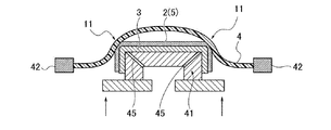
ここで、図5の接着剤2が塗布された芯材3は、図7のように金型41(芯材セット金型)にセットされる。表皮材4は、図10に示すように、クランプ42で挟んだ状態で上下のヒーター43,44によって両面を加熱される。その後、芯材3と表皮材4とは、図11に示すように、重ね合わされる。そして、芯材3ごと金型41を突き上げて芯材3を表皮材4に接触させた後に、図12に示すように、金型41を真空引きすることによって真空吸着が行われる。芯材3や金型41には、予め真空吸引用孔部25,45がそれぞれ形成されている。
(4)上記した車両用内装部品製造方法において、接着剤2が塗布された上記芯材3または表皮材4の角部11およびその近傍に、部分的に接着剤2が塗布されない接着剤未塗布部12を形成して、接着剤未塗布部12で上記芯材3と表皮材4とが接着されないようにすることで、接着剤未塗布部12における表皮材4の局部的な伸びを緩和し、表皮材4の局部的な伸びによる破れを防止する。
具体的には、図13、図14に示すように、接着剤未塗布部12は、芯材3の角部11にマスキングテープ55を貼り付けるなどしてから接着剤2を塗布することによって形成される。マスキングテープ55は、図15に示すように、接着剤2の塗布後に剥がされる。
表皮材4の局部的な伸びによる破れは、図16に示すように、接着剤未塗布部12を形成せずに、芯材3ごと金型41を突き上げて芯材3を表皮材4に接触させることで、芯材3に塗布された接着剤2の粘性によって、表皮材4の芯材3(の角部11)に対する滑り性が阻害されることによって、図17、図18に示すように引き起こされる(破れ部51)。これに対し、接着剤未塗布部12を設けたものは、上記した滑り性の阻害が生じ難く成るので、図19に示すように、破れのない良好なものとなる。
(5)この際、上記芯材3の上記接着剤未塗布部12の位置に空気孔21を設けて、芯材3と表皮材4との貼着時に上記接着剤未塗布部12内に封じ込められる(ことになる)空気が空気孔21から抜けられるようにする。
(6)更に、上記芯材3の上記接着剤未塗布部12に微細凹凸部31を設けて、(金型突き上げ時や、真空引き時に)上記芯材3の上記接着剤未塗布部12に対する上記表皮材4の滑り性を向上させるようにする。
より具体的な車両用内装部品製造方法は、まず、接着剤塗布工程として、図3に示すように、芯材3の角部11をマスキング治具やマスキングテープ55でマスキングし(マスキング工程)、この状態で、図4に示すように、芯材3の表面側に接着剤2を塗布することによって、図5に示すように、芯材3の表面側に接着剤2の層(接着剤塗布層5)と、マスキングによって接着剤2が塗布されていない接着剤未塗布部12とを形成する。
接着剤2は、噴霧ノズル56などを用いて芯材3の表面全体に対して噴射されるようにする。接着剤未塗布部12は、芯材3の表面にマスキングテープ55を貼ったり、マスク部材を取付けたりすることで自然に形成される。
なお、上記した空気孔21と微細凹凸部31とは、接着剤塗布工程の前までに設けておくようにする。
そして、このような芯材3を用いて、真空同時圧着成形を行わせる。
即ち、芯材セット工程で、図7に示すように、芯材3を金型41にセットする。また、表皮加熱工程で、図10に示すように、クランプ42で挟んだ表皮材4を、上下からヒーター43,44で加熱する。そして、金型突き上げ工程で、図11に示すように、金型41にセットされた芯材3の上方に、加熱された表皮材4を配設して、金型41ごと芯材3を表皮材4へ向けて突き上げる。
更に、真空引き工程で、図12に示すように、金型41および芯材3を介して表皮材4を芯材3に真空吸引する。以上により、芯材3に表皮材4が貼着されて車両用内装部品1が成形される。
<作用効果>この実施例によれば、以下のような作用効果を得ることができる。
(作用効果1)
車両用内装部品1は、芯材3または表皮材4の一方に接着剤塗布層5が設けられていると共に、芯材3と(加熱された)表皮材4とが、接着剤塗布層5を介して重ね合わせた状態で真空吸着により固定される(芯材3に表皮材4が貼着される)ことにより製造される。
車両用内装部品1は、芯材3または表皮材4の一方に接着剤塗布層5が設けられていると共に、芯材3と(加熱された)表皮材4とが、接着剤塗布層5を介して重ね合わせた状態で真空吸着により固定される(芯材3に表皮材4が貼着される)ことにより製造される。
この際、芯材3の角部11およびその近傍に対して、部分的に接着剤2が塗布されない接着剤未塗布部12を形成した。これにより、芯材3と表皮材4との貼着時に、芯材3の角部11周辺の接着剤未塗布部12で芯材3と表皮材4とが接着されてしまわないようにすることによって、接着剤未塗布部12における表皮材4の局部的な伸びを緩和し、表皮材4の局部的な伸びによる破れの発生を防止することができる。その結果、表皮材4の破れなどの外観不良をなくして、品質の高い車両用内装部品1を歩留まり良く製造することが可能となる。しかも、芯材3に対する接着剤塗布工程にマスキング工程を追加するだけで良いので、大きな工程の変化がなく、作業員の負担も少ない。
なお、各種の実験の結果、このような表皮材4の破れは、表皮材4が単層で薄いもののような場合に、特に生じ易いことが確認された。破れが生じ易い表皮材4の厚さは、概ね1.5mm未満であった。よって、厚さが1.5mm未満の表皮材4を使用する場合には、必ず芯材3に接着剤未塗布部12を形成してから表皮材4を貼り付けるようにするのが好ましい。なお、厚さが1.5mm以上の表皮材4であっても、角部11の形状などによっては破れが発生することがあるので、その場合には、接着剤未塗布部12を形成するのが望ましい。
(作用効果2)
芯材3における、接着剤未塗布部12の位置に空気孔21を設けた。この空気孔21により、芯材3と表皮材4との貼着時に接着剤未塗布部12の内部に閉じ込められることになる微量の空気を空気孔21から抜くことができるようになる。その結果、芯材3と表皮材4との貼着後に、例えば、接着剤未塗布部12の内部の僅かな隙間に残った微量の空気が熱膨張し、この空気の熱膨張によって表皮材4が伸びて、接着剤2の塗布部分と上記接着剤未塗布部12との間に境界線段差が生じるような不具合の発生を防止することができる。なお、接着剤未塗布部12の内部に残った微量の空気の熱膨張は、例えば、夏場の高温時や、車両用内装部品1の製造後の耐熱性試験の時などに生じ易い。
芯材3における、接着剤未塗布部12の位置に空気孔21を設けた。この空気孔21により、芯材3と表皮材4との貼着時に接着剤未塗布部12の内部に閉じ込められることになる微量の空気を空気孔21から抜くことができるようになる。その結果、芯材3と表皮材4との貼着後に、例えば、接着剤未塗布部12の内部の僅かな隙間に残った微量の空気が熱膨張し、この空気の熱膨張によって表皮材4が伸びて、接着剤2の塗布部分と上記接着剤未塗布部12との間に境界線段差が生じるような不具合の発生を防止することができる。なお、接着剤未塗布部12の内部に残った微量の空気の熱膨張は、例えば、夏場の高温時や、車両用内装部品1の製造後の耐熱性試験の時などに生じ易い。
各種の実験の結果、このような境界線段差は、接着剤2(接着剤塗布層5)の膜厚t(乾燥膜厚)が大きい場合に生じ易く、反対に、接着剤2の膜厚tが小さい場合には見られなかったので、空気孔21は、接着剤2の膜厚tが大きい場合にのみ設けるようにすれば良い。境界線段差が生じる接着剤2の膜厚tは、概ね75μm以上であった(図8参照)。よって、接着剤2の膜厚tが、75μm未満の場合には、空気孔21は、(設けても良いが)特に設けなくても良い。
(作用効果3)
芯材3の接着剤未塗布部12に、微細凹凸部31を設けた。この微細凹凸部31によって、接着剤未塗布部12と表皮材4との間の接触面積が小さくなるため(例えば、点接触に近い状態となるため)、接着剤未塗布部12と表皮材4との間の摩擦抵抗が減少し、その分、滑り性を向上することができる。このことは、特に、表皮材4が、その裏面側に、滑り性の悪い発泡層36を有するような多層構造の場合に有効である。
芯材3の接着剤未塗布部12に、微細凹凸部31を設けた。この微細凹凸部31によって、接着剤未塗布部12と表皮材4との間の接触面積が小さくなるため(例えば、点接触に近い状態となるため)、接着剤未塗布部12と表皮材4との間の摩擦抵抗が減少し、その分、滑り性を向上することができる。このことは、特に、表皮材4が、その裏面側に、滑り性の悪い発泡層36を有するような多層構造の場合に有効である。
以上、実施例を図面により詳述してきたが、実施例は例示にしか過ぎないものである。よって、実施例の構成にのみ限定されるものではなく、要旨を逸脱しない範囲の設計の変更等があっても本件に含まれることは勿論である。また、例えば、各実施例に複数の構成が含まれている場合には、特に記載がなくとも、これらの構成の可能な組合せが本件に含まれることは勿論である。また、複数の実施例や変形例が本件のものとして開示されている場合には、特に記載がなくとも、これらに跨がった構成の組合せのうちの可能なものが本件に含まれることは勿論である。また、図面に描かれている構成については、特に記載がなくとも、本件に含まれることは勿論である。更に、「等」の用語がある場合には、同等のものを含むという意味で用いられている。また、「ほぼ」「約」「程度」などの用語がある場合には、常識的に認められる範囲や精度のものを含むという意味で用いられている。
1 車両用内装部品
2 接着剤
3 芯材
4 表皮材
5 接着剤塗布層
11 角部
12 接着剤未塗布部
21 空気孔
31 微細凹凸部
51 破れ部
2 接着剤
3 芯材
4 表皮材
5 接着剤塗布層
11 角部
12 接着剤未塗布部
21 空気孔
31 微細凹凸部
51 破れ部
本出願は、2015年9月29日に、日本国特許庁に出願された特願2015-191569に基づいて優先権を主張し、その全ての開示は、完全に本明細書で参照により組み込まれる。
Claims (6)
- 芯材または表皮材の一方に接着剤塗布層が設けられていると共に、芯材と表皮材とが、接着剤塗布層を介して重ね合わせた状態で固定され、
前記接着剤塗布層を有する前記芯材または表皮材の角部およびその近傍に対して、部分的に接着剤が塗布されない接着剤未塗布部が形成されていることを特徴とする車両用内装部品。 - 請求項1に記載の車両用内装部品であって、
前記芯材が、前記接着剤未塗布部の位置に、空気孔を有していることを特徴とする車両用内装部品。 - 請求項1または請求項2に記載の車両用内装部品であって、
前記芯材が、前記接着剤未塗布部に、滑り性向上のための微細凹凸部を有していることを特徴とする車両用内装部品。 - 芯材または表皮材の一方に接着剤を塗布すると共に、芯材の表面に、加熱された表皮材を重ね合わせて真空吸着することにより、芯材に表皮材を貼着する車両用内装部品製造方法において、
前記接着剤が塗布された前記芯材または表皮材の角部およびその近傍に、部分的に接着剤が塗布されない接着剤未塗布部を形成して、接着剤未塗布部で前記芯材と表皮材とが接着されないようにすることで、接着剤未塗布部における表皮材の局部的な伸びを緩和し、表皮材の局部的な伸びによる破れを防止することを特徴とする車両用内装部品製造方法。 - 請求項4に記載の車両用内装部品製造方法であって、
前記芯材の前記接着剤未塗布部の位置に空気孔を設けて、芯材と表皮材との貼着時に前記接着剤未塗布部内に封じ込められる空気が空気孔から抜けられるようにすることを特徴とする車両用内装部品製造方法。 - 請求項4または請求項5に記載の車両用内装部品製造方法であって、
前記芯材の前記接着剤未塗布部に微細凹凸部を設けて、前記芯材の前記接着剤未塗布部に対する前記表皮材の滑り性を向上させることを特徴とする車両用内装部品製造方法。
Priority Applications (3)
| Application Number | Priority Date | Filing Date | Title |
|---|---|---|---|
| US15/764,640 US10518642B2 (en) | 2015-09-29 | 2016-09-09 | Vehicle interior component and method for producing same |
| EP16851097.2A EP3357758B1 (en) | 2015-09-29 | 2016-09-09 | Vehicle interior component and method for producing same |
| CN201680056077.8A CN108136971B (zh) | 2015-09-29 | 2016-09-09 | 车辆用内饰件及其制造方法 |
Applications Claiming Priority (2)
| Application Number | Priority Date | Filing Date | Title |
|---|---|---|---|
| JP2015191569A JP6293101B2 (ja) | 2015-09-29 | 2015-09-29 | 車両用内装部品およびその製造方法 |
| JP2015-191569 | 2015-09-29 |
Publications (1)
| Publication Number | Publication Date |
|---|---|
| WO2017056923A1 true WO2017056923A1 (ja) | 2017-04-06 |
Family
ID=58423340
Family Applications (1)
| Application Number | Title | Priority Date | Filing Date |
|---|---|---|---|
| PCT/JP2016/076618 WO2017056923A1 (ja) | 2015-09-29 | 2016-09-09 | 車両用内装部品およびその製造方法 |
Country Status (5)
| Country | Link |
|---|---|
| US (1) | US10518642B2 (ja) |
| EP (1) | EP3357758B1 (ja) |
| JP (1) | JP6293101B2 (ja) |
| CN (1) | CN108136971B (ja) |
| WO (1) | WO2017056923A1 (ja) |
Families Citing this family (3)
| Publication number | Priority date | Publication date | Assignee | Title |
|---|---|---|---|---|
| JP7020188B2 (ja) * | 2018-03-02 | 2022-02-16 | トヨタ自動車株式会社 | インストルメントパネル構造 |
| CN114474877A (zh) * | 2021-12-30 | 2022-05-13 | 上海通领汽车科技股份有限公司 | 覆膜内饰件生产方法及覆膜内饰件 |
| KR102522624B1 (ko) * | 2022-11-24 | 2023-04-18 | 유진에스엠알시오토모티브테크노 주식회사 | 스킨코어조립형 크래쉬패드 어셈블리 |
Citations (6)
| Publication number | Priority date | Publication date | Assignee | Title |
|---|---|---|---|---|
| JPS54169178U (ja) * | 1978-05-18 | 1979-11-29 | ||
| JPS5751417A (en) * | 1980-09-12 | 1982-03-26 | Tamura Plast Seihin Kk | Preparation of cover with leather sheet |
| JPS57150524A (en) * | 1981-03-12 | 1982-09-17 | Toyota Motor Corp | Manufacture of skin covered formed parts |
| JPS6034846A (ja) * | 1984-05-12 | 1985-02-22 | 河西工業株式会社 | 貼合せ成形品の表皮貼着方法 |
| JPH11286050A (ja) * | 1998-02-09 | 1999-10-19 | Honda Motor Co Ltd | 基材・シート材一体成形方法 |
| JP2000343594A (ja) * | 1999-06-04 | 2000-12-12 | Inoac Corp | 表皮の基材貼込み方法 |
Family Cites Families (6)
| Publication number | Priority date | Publication date | Assignee | Title |
|---|---|---|---|---|
| JPS62198443A (ja) * | 1986-02-26 | 1987-09-02 | Kojima Press Co Ltd | 真空成形による非通気性軟質シ−トの接着貼込み方法 |
| JP3011888B2 (ja) | 1996-07-19 | 2000-02-21 | 株式会社イノアックコーポレーション | インストルメントパネルのエアバッグドアの構造 |
| US6265044B1 (en) | 1998-02-05 | 2001-07-24 | Honda Giken Kogyo Kabushiki Kaisha | Method of covering a profiled surface of a base member with a sheet by using bonding under vacuum, and a sheet suitable for use in the method |
| CN201116093Y (zh) * | 2007-11-21 | 2008-09-17 | 比亚迪股份有限公司 | 一种车辆的内饰件结构 |
| JP4976315B2 (ja) * | 2008-01-18 | 2012-07-18 | タカタ株式会社 | エアバッグカバー、インストルメントパネル、エアバッグ装置、エアバッグ収容体 |
| CN201646592U (zh) * | 2010-05-04 | 2010-11-24 | 张清华 | 机动车的内饰面板 |
-
2015
- 2015-09-29 JP JP2015191569A patent/JP6293101B2/ja active Active
-
2016
- 2016-09-09 US US15/764,640 patent/US10518642B2/en active Active
- 2016-09-09 CN CN201680056077.8A patent/CN108136971B/zh active Active
- 2016-09-09 WO PCT/JP2016/076618 patent/WO2017056923A1/ja active Application Filing
- 2016-09-09 EP EP16851097.2A patent/EP3357758B1/en active Active
Patent Citations (6)
| Publication number | Priority date | Publication date | Assignee | Title |
|---|---|---|---|---|
| JPS54169178U (ja) * | 1978-05-18 | 1979-11-29 | ||
| JPS5751417A (en) * | 1980-09-12 | 1982-03-26 | Tamura Plast Seihin Kk | Preparation of cover with leather sheet |
| JPS57150524A (en) * | 1981-03-12 | 1982-09-17 | Toyota Motor Corp | Manufacture of skin covered formed parts |
| JPS6034846A (ja) * | 1984-05-12 | 1985-02-22 | 河西工業株式会社 | 貼合せ成形品の表皮貼着方法 |
| JPH11286050A (ja) * | 1998-02-09 | 1999-10-19 | Honda Motor Co Ltd | 基材・シート材一体成形方法 |
| JP2000343594A (ja) * | 1999-06-04 | 2000-12-12 | Inoac Corp | 表皮の基材貼込み方法 |
Non-Patent Citations (1)
| Title |
|---|
| See also references of EP3357758A4 * |
Also Published As
| Publication number | Publication date |
|---|---|
| CN108136971B (zh) | 2021-06-25 |
| US20180272868A1 (en) | 2018-09-27 |
| CN108136971A (zh) | 2018-06-08 |
| EP3357758B1 (en) | 2021-10-27 |
| JP6293101B2 (ja) | 2018-03-14 |
| EP3357758A1 (en) | 2018-08-08 |
| JP2017065369A (ja) | 2017-04-06 |
| EP3357758A4 (en) | 2018-10-03 |
| US10518642B2 (en) | 2019-12-31 |
Similar Documents
| Publication | Publication Date | Title |
|---|---|---|
| WO2017056923A1 (ja) | 車両用内装部品およびその製造方法 | |
| WO2009120738A9 (en) | Vehicular trim applications using film adhesive in lieu of stitching | |
| JP2007512163A5 (ja) | ||
| JP2022507277A (ja) | 自動車の製造のための方法及びそのために好適な器具 | |
| WO2020143822A1 (zh) | 贴膜方法 | |
| WO2018073140A3 (de) | Verfahren zur herstellung einer versiegelten falzverbindung | |
| US20130316121A1 (en) | Method for manufacturing an inner covering assembly on a member of a forming tool | |
| JP7084004B2 (ja) | 被着体の表面保護方法 | |
| CN111246682A (zh) | 一种盲槽底部焊线焊盘的软硬结合板的制作方法 | |
| TW201408491A (zh) | 泡棉組件及其製造方法及應用該泡棉組件的電子裝置 | |
| JP2017065369A5 (ja) | ||
| JP2016107974A (ja) | オープンコアクラッシュパッド及びその製造方法 | |
| JP4772018B2 (ja) | 内装品の真空成形機及び真空成形方法 | |
| JP2000085088A (ja) | 化粧シート貼り板材の製造装置及び製造方法 | |
| JP4847480B2 (ja) | 外皮および支持材を備える被着材とその製造方法 | |
| JP2006192797A (ja) | 真空成形方法および真空成形型 | |
| JP6453728B2 (ja) | 樹脂成形品の成形方法及び樹脂部材 | |
| JP6460369B2 (ja) | 加飾部品及び加飾部品の製造方法 | |
| JP2017094640A (ja) | 樹脂成形品製造方法および樹脂成形品 | |
| JPS63165119A (ja) | 表皮層張込み内装品の製造方法 | |
| KR200367014Y1 (ko) | 알루미늄 증착 테이프 | |
| JP2017030392A (ja) | 車両用パネルの外周部接合構造 | |
| JP2004322557A (ja) | 自動車内装部品の製造方法 | |
| US10632667B2 (en) | Manufacturing procedure for ceiling trims for vehicles | |
| JP6497729B2 (ja) | 木目込み部を有する自動車用内装材の製造方法 |
Legal Events
| Date | Code | Title | Description |
|---|---|---|---|
| 121 | Ep: the epo has been informed by wipo that ep was designated in this application |
Ref document number: 16851097 Country of ref document: EP Kind code of ref document: A1 |
|
| WWE | Wipo information: entry into national phase |
Ref document number: 15764640 Country of ref document: US |
|
| NENP | Non-entry into the national phase |
Ref country code: DE |
|
| WWE | Wipo information: entry into national phase |
Ref document number: 2016851097 Country of ref document: EP |