WO2017043337A1 - クラッチカバー組立体 - Google Patents
クラッチカバー組立体 Download PDFInfo
- Publication number
- WO2017043337A1 WO2017043337A1 PCT/JP2016/074974 JP2016074974W WO2017043337A1 WO 2017043337 A1 WO2017043337 A1 WO 2017043337A1 JP 2016074974 W JP2016074974 W JP 2016074974W WO 2017043337 A1 WO2017043337 A1 WO 2017043337A1
- Authority
- WO
- WIPO (PCT)
- Prior art keywords
- axial direction
- support portion
- cover assembly
- clutch cover
- support
- Prior art date
- Legal status (The legal status is an assumption and is not a legal conclusion. Google has not performed a legal analysis and makes no representation as to the accuracy of the status listed.)
- Ceased
Links
Images





Classifications
-
- F—MECHANICAL ENGINEERING; LIGHTING; HEATING; WEAPONS; BLASTING
- F16—ENGINEERING ELEMENTS AND UNITS; GENERAL MEASURES FOR PRODUCING AND MAINTAINING EFFECTIVE FUNCTIONING OF MACHINES OR INSTALLATIONS; THERMAL INSULATION IN GENERAL
- F16D—COUPLINGS FOR TRANSMITTING ROTATION; CLUTCHES; BRAKES
- F16D13/00—Friction clutches
- F16D13/22—Friction clutches with axially-movable clutching members
- F16D13/38—Friction clutches with axially-movable clutching members with flat clutching surfaces, e.g. discs
- F16D13/46—Friction clutches with axially-movable clutching members with flat clutching surfaces, e.g. discs in which two axially-movable members, of which one is attached to the driving side and the other to the driven side, are pressed from one side towards an axially-located member
-
- F—MECHANICAL ENGINEERING; LIGHTING; HEATING; WEAPONS; BLASTING
- F16—ENGINEERING ELEMENTS AND UNITS; GENERAL MEASURES FOR PRODUCING AND MAINTAINING EFFECTIVE FUNCTIONING OF MACHINES OR INSTALLATIONS; THERMAL INSULATION IN GENERAL
- F16D—COUPLINGS FOR TRANSMITTING ROTATION; CLUTCHES; BRAKES
- F16D13/00—Friction clutches
- F16D13/58—Details
- F16D13/60—Clutching elements
-
- F—MECHANICAL ENGINEERING; LIGHTING; HEATING; WEAPONS; BLASTING
- F16—ENGINEERING ELEMENTS AND UNITS; GENERAL MEASURES FOR PRODUCING AND MAINTAINING EFFECTIVE FUNCTIONING OF MACHINES OR INSTALLATIONS; THERMAL INSULATION IN GENERAL
- F16D—COUPLINGS FOR TRANSMITTING ROTATION; CLUTCHES; BRAKES
- F16D13/00—Friction clutches
- F16D13/58—Details
- F16D13/70—Pressure members, e.g. pressure plates, for clutch-plates or lamellae; Guiding arrangements for pressure members
- F16D13/71—Pressure members, e.g. pressure plates, for clutch-plates or lamellae; Guiding arrangements for pressure members in which the clutching pressure is produced by springs only
Definitions
- Embodiments of the present invention relate to a clutch cover assembly.
- a diaphragm spring Conventionally, a diaphragm spring, a first wall portion positioned on one side of the diaphragm spring in the axial direction, an axial direction of the diaphragm spring bent from the first wall portion toward the other side in the axial direction and radially outward
- a first support portion supporting the other side surface of the first support portion, and a second support portion projecting from the first wall portion toward the other side in the axial direction and supporting the one side surface of the diaphragm spring in the axial direction.
- the first support portion and the second support portion are arranged in the radial direction or the axial direction, the first support portion is the radial direction of the second support portion. Is bent from the inner root portion to the other side in the axial direction.
- the plate-like member is difficult to bend at a small acute angle, in such a configuration, there is a risk that the first support portion is relatively large and circumvents the radially inner side of the opening of the diaphragm spring. was there. That is, in this type of clutch cover assembly, for example, it is preferable if the first support portion can be configured more compactly.
- the clutch cover assembly of the embodiment includes, for example, a first surface facing one side in the axial direction of the rotation center and a second surface facing the other side in the axial direction, and at least a part thereof
- a diaphragm spring having an opening penetrating the first surface and the second surface, and being positioned on one side of the axial direction of the diaphragm spring and extending along a circumferential direction of the rotation center
- An annular first wall portion bent from the first wall portion toward the other side in the axial direction, extending along the axial direction, penetrating the opening portion, and the first portion of the opening portion.
- the second support portion is cut and raised from the first wall portion. Therefore, for example, the second support portion can be obtained relatively easily by the configuration cut and raised from the first wall portion.
- the second support portion is provided with a first fulcrum portion that is in contact with the first surface. Therefore, for example, the number of parts of the clutch cover assembly can be reduced as compared with a case where a member serving as a fulcrum is provided separately from the second support portion. Therefore, for example, labor and cost required for manufacturing the clutch cover assembly are likely to be reduced.
- the first support portion is provided with a second fulcrum portion that is in contact with the second surface. Therefore, for example, the number of parts of the clutch cover assembly can be reduced as compared with a case where a member serving as a fulcrum is provided separately from the first support portion. Therefore, for example, labor and cost required for manufacturing the clutch cover assembly are likely to be reduced.
- the clutch cover assembly of the embodiment has, for example, a first surface facing one side in the axial direction of the rotation center and a second surface facing the other side in the axial direction, and at least A diaphragm spring partially provided with an opening penetrating the first surface and the second surface, and positioned on one side of the axial direction of the diaphragm spring along the circumferential direction of the rotation center
- An annular first wall portion extending from the first wall portion, bent toward the other side in the axial direction, extending along the axial direction and penetrating the opening, and the opening of the opening
- a first support portion that is bent toward the outside in the radial direction of the rotation center on the side opposite to the first wall portion, and that supports the second surface; and the other axially extending from the first wall portion A second support portion cut and raised toward the side to support the first surface;
- the first support portion can be configured without greatly detouring radially inward of the opening by the configuration in which the second support portion is cut and raised from the first wall portion. Therefore, for example, the first support portion can be configured to be shorter, and thus, for example, the space around the first support portion can be used more effectively, or the clutch cover assembly can be configured to be lighter. obtain.
- FIG. 1 is an exemplary front view of the clutch cover assembly of the first embodiment.
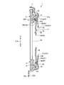
- FIG. 2 is an exemplary cross-sectional view of the clutch cover assembly of the first embodiment.
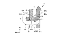
- 3 is a cross-sectional view taken along the line III-III in FIG. 4 is a cross-sectional view taken along the line IV-IV in FIG.
- FIG. 5 is an exemplary cross-sectional view of a portion of the clutch cover assembly of the second embodiment.
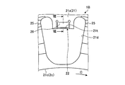
- FIG. 6 is an exemplary front view of a part of the cover member of the clutch cover assembly according to the third embodiment.
- 7 is a sectional view taken along line VII-VII in FIG.
- FIG. 8 is an exemplary cross-sectional view of a portion of the clutch cover assembly of the fourth embodiment.
- the clutch including the clutch cover assembly 1 shown in FIG. 2 is located, for example, between the engine and the transmission, and changes the transmission state of the driving force from the engine to the transmission.
- the clutch cover assembly 1 is attached to, for example, a flywheel at the rear stage of the engine, and covers the pressure plate 5, the clutch disk, and the like.
- the clutch including the clutch cover assembly 1 is not limited to be provided between the engine and the transmission, but can be provided between the other two rotating elements, for example, between the engine and the motor generator. It can also be applied to a manual transmission device.
- the clutch cover assembly 1 is provided so as to be rotatable around the rotation axis Ax shown in FIGS.
- the rotation axis Ax is an example of a rotation center.
- the rotation axis Ax substantially coincides with the output shaft of the engine and the input shaft of the transmission.
- the axial direction indicates the axial direction of the rotational axis Ax
- the radial direction indicates the radial direction of the rotational axis Ax
- the circumferential direction indicates the circumferential direction of the rotational axis Ax.
- the axial transmission side that is, the right side in FIG. 2 is defined as one axial direction
- the axial engine side that is, the left side in FIG.
- the other side in the axial direction is indicated by an arrow X
- the outer side in the radial direction is indicated by an arrow R
- one side in the circumferential direction is indicated by an arrow C.
- the clutch cover assembly 1 includes, for example, a cover member 2, a diaphragm spring 3, and a ring member 4.
- the diaphragm spring 3 is configured in, for example, an annular shape around the rotation axis Ax, and has a plate shape extending along the circumferential direction (C direction) and the radial direction (R direction). It is configured.
- the diaphragm spring 3 has a first surface 3a facing the one side in the axial direction (X direction), that is, the right side in FIG. 2, and a second surface 3b facing the other side in the axial direction.
- the diaphragm spring 3 is provided with an opening 3d penetrating the first surface 3a and the second surface 3b.
- the opening 3d includes, for example, a circular portion 3e positioned at the center of the diaphragm spring 3, and a plurality of openings extending radially outward from the circular portion 3e in the radial direction (R direction).
- Slit portions 3f, and cutout portions 3g extending along the circumferential direction (C direction) from the radially outer ends of the respective slit portions 3f.
- an annular and plate-like portion on the outer side in the radial direction from the notch portion 3 g in the diaphragm spring 3 is the base portion 31.
- the elongated triangular portion that is pointed inward in the radial direction between two slit portions 3 f adjacent in the circumferential direction is the lever portion 32.
- the diaphragm spring 3 can be made of, for example, a metal material.
- the cover member 2 includes, for example, a first wall portion 21, a second wall portion 23, a first support portion 22, and a second support portion 25. ing.
- the first wall portion 21 is formed in an annular shape around the rotation axis Ax, and has a plate shape extending along the circumferential direction (C direction) and the radial direction (R direction). It is configured.
- the first wall portion 21 is located on one side of the diaphragm spring 3 in the axial direction (X direction), that is, on the right side in FIG. 2, and covers at least a part of the first surface 3a.
- the first wall portion 21 has a surface 21a facing one side in the axial direction (X direction), a surface 21b facing the other side in the axial direction, and a surface facing the inner side in the radial direction (R direction). 21c. As shown in FIG. 1, the surface 21 c forms a circular opening 2 c positioned at the center of the cover member 2. Further, the first wall portion 21 is provided with a plurality of openings 21d spaced from each other in the circumferential direction (C direction). The opening 21d is, for example, a through hole that penetrates the surface 21a and the surface 21b. In this embodiment, the 1st support part 22 is provided in the edge part of the radial direction outer side of the opening part 21d.
- the first wall portion 21 can also be referred to as an end wall, a flange, a first cover portion, or the like.
- the second wall portion 23 protrudes from the outer end portion in the radial direction (R direction) of the first wall portion 21 to the other side in the axial direction (X direction), that is, the left side in FIG.
- the second wall portion 23 is generally formed in a substantially cylindrical shape around the rotation axis Ax.
- the second wall portion 23 is located radially outside the diaphragm spring 3 and the pressure plate 5 and covers at least a part of the diaphragm spring 3 and the pressure plate 5.
- the second wall portion 23 can also be referred to as an outer peripheral wall, a second cover portion, or the like.
- a flange portion 23c projecting outward in the radial direction (R direction) is provided on the other side of the second wall portion 23 in the axial direction (X direction), that is, on the left end in FIG.
- the flange portion 23c is provided with an opening 23d used for coupling with the flywheel.
- the flange portion 23c and the flywheel can be coupled to each other by a coupling tool (not shown) that penetrates each opening 23d in the axial direction. Therefore, the cover member 2 and the flywheel rotate integrally around the rotation axis Ax.
- the first support 22 protrudes from the edge of the opening 21d of the first wall 21 to the other side in the axial direction (X direction), that is, the left side in FIG.
- X direction axial direction
- the plurality of first support portions 22 are axially overlapped with each of the plurality of cutout portions 3 g at intervals in the circumferential direction (C direction). It is provided as follows.
- the first support portion 22 includes, for example, two bent portions 22a and 22c, two wall portions 22b and 22d, and the like.
- the wall portion 22b is connected to the first wall portion 21 via a bent portion 22a.
- the wall portion 22 b extends from the first wall portion 21 toward the other side in the axial direction, that is, the left side in FIG. 3, and penetrates the cutout portion 3 g of the diaphragm spring 3.
- the wall portion 22b can also be referred to as a protruding portion, a connecting portion, an insertion portion, or the like.
- the wall portion 22d is connected to the wall portion 22b via the bent portion 22c on the opposite side to the first wall portion 21 of the cutout portion 3g in the axial direction (X direction).
- the wall portion 22d extends from the wall portion 22b to the outside in the radial direction (R direction) and one side in the axial direction, that is, obliquely upward to the right in FIG.
- the wall portion 22d can be configured, for example, by bending the diaphragm spring 3 and the ring member 4 at a predetermined position outside the wall portion 22b in the radial direction.
- the wall portion 22 d can support the second surface 3 b of the diaphragm spring 3 via the ring member 4.
- the wall portion 22d can also be referred to as a protruding portion, a claw portion, a hooking portion, a caulking portion, or the like.
- the second support portion 25 protrudes from the first wall portion 21 to the other side in the axial direction (X direction), that is, the left side in FIG. As shown also in FIG. 4, in this embodiment, for example, by applying a process such as pressing to a part of the first wall portion 21, the second bent in a convex state on the other side in the axial direction.
- a support portion 25 is formed.
- the second support portion 25 is provided with a first fulcrum portion 25 a that comes into contact with the first surface 3 a of the diaphragm spring 3.
- the first fulcrum portion 25a is configured in a curved line in the line of sight shown in FIG.
- the 2nd support part 25 is provided ranging between the two opening parts 21d adjacent to the circumferential direction of the 1st wall part 21, for example. Yes. That is, the second support portion 25 is provided at a position shifted from the first support portion 22 of the first wall portion 21 in the circumferential direction (C direction). If the first support portion 22 is bent from the radially inner root portion of the second support portion 25 shown in FIG. 4 to the other side in the axial direction (X direction), the first support portion 22 is provided. However, there is a risk that the inner side of the cutout portion 3g in the radial direction is relatively large and circumvents it.
- the first support portion 22 can be provided at a position shifted from the second support portion 25 of the first wall portion 21 in the circumferential direction. 22 can be configured without greatly detouring to the inside in the radial direction of the cutout portion 3g. Therefore, for example, the first support portion 22 is easily configured to be shorter, and as a result, the space around the first support portion 22 can be used more effectively, or the clutch cover assembly 1 can be configured to be lighter. obtain.
- the cover member 2 can be made of a metal material, for example.
- the ring member 4 is configured, for example, by bending a metal wire having a circular cross section into an annular shape.
- the ring member 4 is, for example, an endless O-ring in which end portions in the longitudinal direction are coupled by welding or the like.
- the ring member 4 may be a C-ring with ends that are close to each other in the longitudinal direction.
- the ring member 4 can be made of, for example, a metal material.
- the ring member 4 can also be referred to as a pivot ring or the like.
- the diaphragm spring 3 is supported on the cover member 2 so as to be swingable with the ring member 4 and the first fulcrum portion 25 a of the second support portion 25 as fulcrums.
- the ring member 4 is positioned on the other side in the axial direction (X direction) of the base portion of the lever portion 32, that is, the connecting portion between the base portion 31 and the lever portion 32, and the first fulcrum portion 25 a It is located on one side in the axial direction of the root portion.
- the ring member 4 contacts the second surface 3b of the diaphragm spring 3 and receives a load from the diaphragm spring 3 to the other side in the axial direction.
- the first fulcrum portion 25 a abuts on the first surface 3 a of the diaphragm spring 3 and receives a load from the diaphragm spring 3 toward one side in the axial direction.
- FIG. 2 shows a connection state in which the rotation element on the engine side and the rotation element on the transmission side are connected.
- the diaphragm spring 3 pushes the pressure plate 5 toward the other side in the axial direction (X direction), that is, the left side in FIG. 2 with elastic deformation.
- the clutch disk is sandwiched between the pressure plate 5 and the flywheel by the load acting on the pressure plate 5 from the diaphragm spring 3, and the engine-side rotation element and the transmission-side rotation element are connected. That is, in the connected state of FIG. 2, the driving force is transmitted from the engine-side rotating element to the transmission-side rotating element.
- the diaphragm spring 3 is supported so as to be able to swing with the ring member 4 and the first fulcrum portion 25a as a fulcrum, for example, the diaphragm spring 3 swings with the two ring members 4 as fulcrums.
- the number of parts of the clutch cover assembly 1 can be reduced as compared with the case where it is supported. Therefore, for example, labor and cost required for manufacturing the clutch cover assembly 1 are likely to be reduced.
- the clutch cover assembly 1 includes the first surface 3a facing the one side in the axial direction (X direction) of the rotation axis Ax (center) and the other side in the axial direction.
- a diaphragm spring 3, and a diaphragm spring 3 having an opening 3d penetrating at least part of the first surface 3a and the second surface 3b.
- An annular first wall portion 21 located on one side in the axial direction and extending along the circumferential direction (C direction) of the rotation axis Ax, and bent from the first wall portion 21 toward the other side in the axial direction.
- the first support portion 22 that supports 3b and the first support portion 22 of the first wall portion 21 are circumferential.
- a second support portion 25 supporting the projected first surface 3a toward the other side in the axial direction from the position shifted toward had includes a cover member 2, the.
- the 1st support part 22 can be provided in the position shifted from the 2nd support part 25 of the 1st wall part 21 in the circumferential direction, for example, the 1st support part Compared to the case where the portion 22 is bent from the radially inner base portion of the second support portion 25 to the other side in the axial direction, the first support portion 22 is largely detoured to the radially inner side of the opening 3d. It can be configured without making it. Therefore, for example, the first support portion 22 is easily configured to be shorter, and as a result, for example, the space around the first support portion 22 can be used more effectively, or the clutch cover assembly 1 can be configured to be lighter. It can be done.
- the bending of the 1st support part 22 is easier and smoother.
- the second support portion 25 is provided with a first fulcrum portion 25a in contact with the first surface 3a. Therefore, according to the present embodiment, for example, the number of parts of the clutch cover assembly 1 can be reduced as compared with a case where a member serving as a fulcrum is provided separately from the second support portion 25. Therefore, for example, labor and cost required for manufacturing the clutch cover assembly 1 are likely to be reduced.
- the clutch cover assembly 1A of the embodiment shown in FIG. 5 has the same configuration as the clutch cover assembly 1 of the first embodiment. Therefore, also according to this embodiment, the same result (effect) based on the same configuration as that of the first embodiment can be obtained.
- the first wall portion 21 is provided with a second support portion 26.
- a slit-shaped opening 21 s is provided on the peripheral edge of the second support portion 26 of the first wall portion 21.
- the opening 21s may be formed in a substantially U shape that is open toward the outside in the radial direction (R direction) when viewed in the axial direction (X direction) (not shown).
- the second support portion 26 is cut and raised from the opening portion 21 s of the first wall portion 21 to the other side in the axial direction.
- the second support portion 26 is provided with a first fulcrum portion 26 a that comes into contact with the first surface 3 a of the diaphragm spring 3.
- the first fulcrum portion 26a is configured in a curved line in the line of sight shown in FIG.
- the first fulcrum portion 26a may be configured in a curved shape, for example, by performing processing such as polishing. Therefore, according to the present embodiment, for example, the second support portion 26 can be obtained relatively easily by the configuration cut and raised from the first wall portion 21.
- the curvature radius of the 1st fulcrum part 26a is small compared with the 2nd support part 25 comprised by bending a part of 1st wall part 21 on the other side of an axial direction. There is also an advantage that it is easy to become. Thereby, the contact area between the first fulcrum part 26a and the first surface 3a can be easily reduced, and the operating force of the diaphragm spring 3 can be reduced.
- the clutch cover assembly 1B of the embodiment shown in FIGS. 6 and 7 has the same configuration as the clutch cover assembly 1A of the second embodiment. Therefore, also according to this embodiment, the same result (effect) based on the same configuration as that of the first embodiment can be obtained.
- the second support portion 26 and the first support portion 22 are not displaced in the circumferential direction (C direction) in the radial direction or the axial direction. They are arranged side by side.
- the slit-shaped opening 21 t from which the second support portion 26 is cut and raised is provided across the first wall portion 21 and at least a part of the first support portion 22.
- the opening 21t is configured in a substantially U shape opened toward the outside in the radial direction (R direction) in the line of sight shown in FIG. And the 2nd support part 26 is cut and raised to the other side of the axial direction from the opening part 21t.
- the second support portion 25 is provided at a position shifted from the first support portion 22 of the first wall portion 21 in the circumferential direction (C direction).
- the first support portion 22 is in the radial direction of the second support portion 25.
- the first support portion 22 can be configured without greatly detouring to the inner side in the radial direction of the cutout portion 3g. Therefore, for example, the first support portion 22 is easily configured to be shorter, and thus, for example, the space around the first support portion 22 can be used more effectively, or the clutch cover assembly 1B is configured to be lighter. It can be done.
- the clutch cover assembly 1C of the embodiment shown in FIG. 8 has the same configuration as the clutch cover assembly 1B of the third embodiment. Therefore, according to this embodiment, the same result (effect) based on the same configuration as that of the third embodiment can be obtained.
- the first support portion 22 ⁇ / b> A is provided with a second fulcrum portion 22 s that contacts the second surface 3 b of the diaphragm spring 3.
- the second fulcrum portion 22s is provided, for example, at the radially outer end of one surface of the wall portion 22d in the axial direction (X direction).
- the second fulcrum part 22s is configured in a curved line in the line of sight shown in FIG.
- the second fulcrum portion 22s may be configured in a curved shape by performing processing such as polishing.
- the number of parts of the clutch cover assembly 1C can be reduced as compared with a case where a member serving as a fulcrum is provided separately from the first support portion 22A. Therefore, for example, the effort and cost required for manufacturing the clutch cover assembly 1C are likely to be reduced.
Landscapes
- Engineering & Computer Science (AREA)
- General Engineering & Computer Science (AREA)
- Mechanical Engineering (AREA)
- Mechanical Operated Clutches (AREA)
Abstract
実施形態のクラッチカバー組立体は、例えば、軸方向の一方側を向いた第一の面と、軸方向の他方側を向いた第二の面と、を有し、少なくとも一部に第一の面と第二の面とを貫通した開口部が設けられた、ダイヤフラムスプリングと、ダイヤフラムスプリングの軸方向の一方側に位置され周方向に沿って延びた環状の第一の壁部と、第一の壁部から軸方向の他方側に向けて屈曲され軸方向に沿って延びて開口部を貫通するとともに開口部の第一の壁部とは反対側で径方向の外側に向けて屈曲され第二の面を支持した第一の支持部と、第一の壁部の第一の支持部とは周方向にずれた位置から軸方向の他方側に向けて突出し第一の面を支持した第二の支持部と、を有した、カバー部材と、を備える。
Description
本発明の実施形態は、クラッチカバー組立体に関する。
従来、ダイヤフラムスプリングと、ダイヤフラムスプリングの軸方向の一方側に位置された第一の壁部、第一の壁部から軸方向の他方側かつ径方向の外側に向けて屈曲されダイヤフラムスプリングの軸方向の他方側の面を支持した第一の支持部、および第一の壁部から軸方向の他方側へ向けて突出しダイヤフラムスプリングの軸方向の一方側の面を支持した第二の支持部、を有したカバー部材と、を備えたクラッチカバー組立体が、知られている。
上記従来のクラッチカバー組立体では、第一の支持部と第二の支持部とが径方向または軸方向に並んで配置されているため、第一の支持部が第二の支持部の径方向の内側の根元部分から軸方向の他方側へ屈曲されている。一般に、板状部材は小さい鋭角で曲げることが難しいため、このような構成では、第一の支持部がダイヤフラムスプリングの開口部のより径方向の内側を比較的大きく迂回して大きくなってしまう虞があった。すなわち、この種のクラッチカバー組立体では、例えば、第一の支持部をよりコンパクトに構成できれば、好ましい。
実施形態のクラッチカバー組立体は、例えば、回転中心の軸方向の一方側を向いた第一の面と、上記軸方向の他方側を向いた第二の面と、を有し、少なくとも一部に上記第一の面と上記第二の面とを貫通した開口部が設けられた、ダイヤフラムスプリングと、上記ダイヤフラムスプリングの上記軸方向の一方側に位置され上記回転中心の周方向に沿って延びた環状の第一の壁部と、上記第一の壁部から上記軸方向の他方側に向けて屈曲され上記軸方向に沿って延びて上記開口部を貫通するとともに上記開口部の上記第一の壁部とは反対側で上記回転中心の径方向の外側に向けて屈曲され上記第二の面を支持した第一の支持部と、上記第一の壁部の上記第一の支持部とは上記周方向にずれた位置から上記軸方向の他方側に向けて突出し上記第一の面を支持した第二の支持部と、を有した、カバー部材と、を備える。よって、第一の支持部を第一の壁部の第二の支持部とは周方向にずれた位置に設けることができるため、例えば、第一の支持部が第二の支持部の径方向の内側の根元部分から軸方向の他方側へ屈曲された場合と比べて、第一の支持部を開口部の径方向の内側に大きく迂回させることなく構成することができる。よって、例えば、第一の支持部がより短く構成されやすくなり、ひいては、例えば、第一の支持部の周囲の空間をより有効に活用できたり、クラッチカバー組立体をより軽量に構成できたりし得る。
また、上記クラッチカバー組立体では、例えば、上記第二の支持部は、上記第一の壁部から切り起こされている。よって、例えば、第一の壁部から切り起こされた構成によって、第二の支持部が比較的容易に得られうる。
また、上記クラッチカバー組立体では、例えば、上記第二の支持部には、上記第一の面と接触した第一の支点部が設けられる。よって、例えば、第二の支持部とは別に支点となる部材が設けられた場合と比べて、クラッチカバー組立体の部品点数を減らすことができる。よって、例えば、クラッチカバー組立体の製造に要する手間や費用が減りやすい。
また、上記クラッチカバー組立体では、例えば、上記第一の支持部には、上記第二の面と接触した第二の支点部が設けられる。よって、例えば、第一の支持部とは別に支点となる部材が設けられた場合と比べて、クラッチカバー組立体の部品点数を減らすことができる。よって、例えば、クラッチカバー組立体の製造に要する手間や費用が減りやすい。
また、実施形態のクラッチカバー組立体は、例えば、回転中心の軸方向の一方側を向いた第一の面と、上記軸方向の他方側を向いた第二の面と、を有し、少なくとも一部に上記第一の面と上記第二の面とを貫通した開口部が設けられた、ダイヤフラムスプリングと、上記ダイヤフラムスプリングの上記軸方向の一方側に位置され上記回転中心の周方向に沿って延びた環状の第一の壁部と、上記第一の壁部から上記軸方向の他方側に向けて屈曲され上記軸方向に沿って延びて上記開口部を貫通するとともに上記開口部の上記第一の壁部とは反対側で上記回転中心の径方向の外側に向けて屈曲され上記第二の面を支持した第一の支持部と、上記第一の壁部から上記軸方向の他方側に向けて切り起こされて上記第一の面を支持した第二の支持部と、を有した、カバー部材と、を備える。よって、例えば、第二の支持部が第一の壁部から切り起こされた構成によって、第一の支持部を開口部の径方向の内側に大きく迂回させることなく構成することができる。よって、例えば、第一の支持部がより短く構成されやすくなり、ひいては、例えば、第一の支持部の周囲の空間をより有効に活用できたり、クラッチカバー組立体をより軽量に構成できたりし得る。
以下、本発明の例示的な実施形態が開示される。以下に示される実施形態の構成、ならびに当該構成によってもたらされる作用、結果、および効果は、あくまで一例である。本発明は、以下の実施形態に開示される構成以外によっても実現可能である。また、本発明によれば、構成によって得られる種々の効果のうち少なくとも一つを得ることが可能である。
また、以下に開示される複数の実施形態には、同様の構成要素が含まれる。よって、以下では、それら同様の構成要素には共通の符号が付与されるとともに、重複する説明が省略される。
<第1実施形態>
図2に示されるクラッチカバー組立体1を含むクラッチは、例えば、エンジンとトランスミッションとの間に位置され、エンジンからトランスミッションへの駆動力の伝達状態を変化させる。クラッチカバー組立体1は、例えば、エンジン後段のフライホイールに取り付けられ、プレッシャプレート5や、クラッチディスク等を覆う。なお、クラッチカバー組立体1を含むクラッチは、エンジンとトランスミッションとの間には限らず、他の二つの回転要素間、例えば、エンジンとモータジェネレータとの間に設けることが可能であるし、自動マニュアルトランスミッション装置に適用することも可能である。
図2に示されるクラッチカバー組立体1を含むクラッチは、例えば、エンジンとトランスミッションとの間に位置され、エンジンからトランスミッションへの駆動力の伝達状態を変化させる。クラッチカバー組立体1は、例えば、エンジン後段のフライホイールに取り付けられ、プレッシャプレート5や、クラッチディスク等を覆う。なお、クラッチカバー組立体1を含むクラッチは、エンジンとトランスミッションとの間には限らず、他の二つの回転要素間、例えば、エンジンとモータジェネレータとの間に設けることが可能であるし、自動マニュアルトランスミッション装置に適用することも可能である。
クラッチカバー組立体1は、図1,2に示される回転軸Ax回りに回転可能に設けられている。回転軸Axは、回転中心の一例である。回転軸Axは、例えば、エンジンの出力軸およびトランスミッションの入力軸と略一致している。なお、以下の説明では、軸方向は回転軸Axの軸方向、径方向は回転軸Axの径方向、周方向は回転軸Axの周方向を示す。また、以下の説明では、便宜上、軸方向のトランスミッション側、すなわち図2の右側を軸方向の一方側とし、軸方向のエンジン側、すなわち図2の左側を軸方向の他方側とする。また、図中、軸方向の他方側を矢印Xで示し、径方向の外側を矢印Rで示し、周方向の一方側を矢印Cで示す。
図2に示されるように、クラッチカバー組立体1は、例えば、カバー部材2と、ダイヤフラムスプリング3と、リング部材4と、を備える。
図1に示されるように、ダイヤフラムスプリング3は、例えば、回転軸Ax回りの円環状に構成されるとともに、周方向(C方向)および径方向(R方向)に沿って広がった板状に、構成されている。ダイヤフラムスプリング3は、軸方向(X方向)の一方側、すなわち図2の右側を向いた第一の面3aと、軸方向の他方側を向いた第二の面3bと、を有する。
また、ダイヤフラムスプリング3には、第一の面3aと第二の面3bとを貫通した開口部3dが設けられている。図1に示されるように、開口部3dは、例えば、ダイヤフラムスプリング3の中心部に位置された円形部分3eと、円形部分3eから径方向(R方向)の外側に向かって放射状に延びた複数のスリット部分3fと、各スリット部分3fの径方向の外側の端部から周方向(C方向)に沿って広がった切欠部分3gと、を有している。本実施形態では、ダイヤフラムスプリング3のうち、切欠部分3gよりも径方向の外側の円環状かつ板状の部分が、ベース部31である。また、ダイヤフラムスプリング3のうち、周方向に隣接した二つのスリット部分3fに挟まれて径方向の内側に向けて尖った細長い三角形状の部分が、レバー部32である。ダイヤフラムスプリング3は、例えば、金属材料で構成されうる。
図2に示されるように、カバー部材2は、例えば、第一の壁部21と、第二の壁部23と、第一の支持部22と、第二の支持部25と、を有している。図1にも示されるように、第一の壁部21は、回転軸Ax回りの円環状に構成されるとともに、周方向(C方向)および径方向(R方向)に沿って広がった板状に、構成されている。第一の壁部21は、ダイヤフラムスプリング3の軸方向(X方向)の一方側、すなわち図2の右側に位置され、第一の面3aの少なくとも一部を覆っている。
また、第一の壁部21は、軸方向(X方向)の一方側を向いた面21aと、軸方向の他方側を向いた面21bと、径方向(R方向)の内側を向いた面21cと、を有する。図1に示されるように、面21cは、カバー部材2の中心部に位置された円形状の開口部2cを構成している。また、第一の壁部21には、周方向(C方向)に互いに間隔をあけて複数の開口部21dが設けられている。開口部21dは、例えば、面21aと面21bとを貫通した貫通孔である。本実施形態では、開口部21dの径方向の外側の縁部に、第一の支持部22が設けられている。第一の壁部21は、端壁や、フランジ、第一の覆部等とも称されうる。
第二の壁部23は、第一の壁部21の径方向(R方向)の外側の端部から軸方向(X方向)の他方側、すなわち図2の左側に突出している。第二の壁部23は、全体としては回転軸Ax回りの略円筒状に構成されている。第二の壁部23は、ダイヤフラムスプリング3とプレッシャプレート5との径方向の外側に位置され、これらダイヤフラムスプリング3およびプレッシャプレート5の少なくとも一部を覆っている。第二の壁部23は、外周壁や、第二の覆部等とも称されうる。
また、第二の壁部23の軸方向(X方向)の他方側、すなわち図2の左側の端部には、径方向(R方向)の外側に張り出したフランジ部23cが設けられている。フランジ部23cには、フライホイールとの結合に用いられる開口部23dが設けられている。フランジ部23cとフライホイールとは、それぞれの開口部23dを軸方向に貫通する不図示の結合具によって互いに結合されうる。よって、カバー部材2とフライホイールとは、回転軸Ax回りに一体に回転する。
第一の支持部22は、第一の壁部21の開口部21dの縁部から軸方向(X方向)の他方側、すなわち図2の左側に突出している。図1に示されるように、本実施形態では、例えば、複数の第一の支持部22が、周方向(C方向)に互いに間隔をあけて、複数の切欠部分3gのそれぞれと軸方向に重なるように設けられている。
図3に示されるように、第一の支持部22は、例えば、二つの屈曲部22a,22cや、二つの壁部22b,22d等を有する。壁部22bは、第一の壁部21に屈曲部22aを介して接続されている。本実施形態では、壁部22bは、第一の壁部21から軸方向の他方側、すなわち図3の左側に向かって延び、ダイヤフラムスプリング3の切欠部分3gを貫通している。壁部22bは、突出部や、接続部、挿通部等とも称されうる。
また、壁部22dは、切欠部分3gの第一の壁部21とは軸方向(X方向)の反対側で、壁部22bに屈曲部22cを介して接続されている。本実施形態では、壁部22dは、壁部22bから径方向(R方向)の外側かつ軸方向の一方側、すなわち図3の右斜め上側に向かって延びている。壁部22dは、例えば、ダイヤフラムスプリング3とリング部材4とが壁部22bの径方向の外側の所定位置に配置された後、折り曲げ加工等されることによって構成されうる。本実施形態では、壁部22dは、リング部材4を介してダイヤフラムスプリング3の第二の面3bを支持することができる。壁部22dは、突出部や、爪部、引掛部、カシメ部等とも称されうる。
第二の支持部25は、第一の壁部21から軸方向(X方向)の他方側、すなわち図2の左側に突出している。図4にも示されるように、本実施形態では、例えば、第一の壁部21の一部にプレス等の加工を施すことによって、軸方向の他方側に凸の状態で曲がった第二の支持部25が形成されている。また、本実施形態では、第二の支持部25には、ダイヤフラムスプリング3の第一の面3aと接触する第一の支点部25aが設けられている。第一の支点部25aは、例えば、図4に示される視線では、曲線状に構成されている。
そして、図1に示されるように、本実施形態では、例えば、第二の支持部25は、第一の壁部21の周方向に隣接した二つの開口部21dの間に亘って設けられている。すなわち、第二の支持部25は、第一の壁部21の第一の支持部22とは周方向(C方向)にずれた位置に設けられている。仮に、第一の支持部22が図4に示される第二の支持部25の径方向の内側の根元部分から軸方向(X方向)の他方側へ屈曲された場合、第一の支持部22が切欠部分3gのより径方向の内側を比較的大きく迂回して大きくなってしまう虞がある。その点、本実施形態によれば、第一の支持部22を第一の壁部21の第二の支持部25とは周方向にずれた位置に設けることができるため、第一の支持部22を切欠部分3gの径方向の内側に大きく迂回させることなく構成することができる。よって、例えば、第一の支持部22がより短く構成されやすくなり、ひいては第一の支持部22の周囲の空間をより有効に活用できたり、クラッチカバー組立体1をより軽量に構成できたりし得る。カバー部材2は、例えば、金属材料で構成されうる。
リング部材4は、例えば、断面が円形の金属材料の線材が円環状に屈曲されて構成されている。本実施形態では、リング部材4は、例えば、長手方向の端部同士が溶接等によって結合された無端のOリングである。なお、リング部材4は、長手方向の端部同士が近接した有端のCリングでもよい。リング部材4は、例えば、金属材料で構成されうる。リング部材4は、ピボットリング等とも称されうる。
図4に示されるように、本実施形態では、例えば、ダイヤフラムスプリング3は、カバー部材2に、リング部材4および第二の支持部25の第一の支点部25aを支点として揺動可能に支持されている。リング部材4は、レバー部32の根元部分、すなわちベース部31とレバー部32との接続部分の軸方向(X方向)の他方側に位置され、第一の支点部25aは、レバー部32の根元部分の軸方向の一方側に位置されている。リング部材4は、ダイヤフラムスプリング3の第二の面3bに当接し、当該ダイヤフラムスプリング3から軸方向の他方側へ荷重を受ける。また、第一の支点部25aは、ダイヤフラムスプリング3の第一の面3aに当接し、当該ダイヤフラムスプリング3から軸方向の一方側へ荷重を受ける。
本実施形態では、例えば、図2に示されるカバー部材2やフライホイール等を含むエンジン側の回転要素と、クラッチディスク等を含むトランスミッション側の回転要素とが、プレッシャプレート5を介して接続可能に構成されている。図2には、エンジン側の回転要素とトランスミッション側の回転要素とが接続されている接続状態が示されている。この状態では、ダイヤフラムスプリング3は、弾性変形を伴って、プレッシャプレート5を軸方向(X方向)の他方側、すなわち図2の左側へ向けて押している。このダイヤフラムスプリング3からプレッシャプレート5に作用する荷重によって、クラッチディスクがプレッシャプレート5とフライホイールとの間に挟まれて、エンジン側の回転要素とトランスミッション側の回転要素とが接続される。すなわち、図2の接続状態では、エンジン側の回転要素からトランスミッション側の回転要素へ駆動力が伝達される。
一方、不図示のレリーズベアリングが軸方向(X方向)の他方側、すなわち図2の左側へ移動してレバー部32を軸方向の他方側へ押すと、レバー部32は図2の状態よりも軸方向の他方側へ変位するとともに、ベース部31は図2の状態よりも軸方向の一方側へ変位する。これにより、クラッチディスクがプレッシャプレート5とフライホイールとの間に挟まれた状態が解除され、エンジン側の回転要素とトランスミッション側の回転要素との間が遮断されて駆動力が伝達されない遮断状態となる。本実施形態によれば、ダイヤフラムスプリング3がリング部材4および第一の支点部25aを支点として揺動可能に支持されているため、例えば、ダイヤフラムスプリング3が二つのリング部材4を支点として揺動可能に支持された場合と比べて、クラッチカバー組立体1の部品点数を減らすことができる。よって、例えば、クラッチカバー組立体1の製造に要する手間や費用が減りやすい。
以上のように、本実施形態では、例えば、クラッチカバー組立体1は、回転軸Ax(中心)の軸方向(X方向)の一方側を向いた第一の面3aと、軸方向の他方側を向いた第二の面3bと、を有し、少なくとも一部に第一の面3aと第二の面3bとを貫通した開口部3dが設けられた、ダイヤフラムスプリング3と、ダイヤフラムスプリング3の軸方向の一方側に位置され回転軸Axの周方向(C方向)に沿って延びた環状の第一の壁部21と、第一の壁部21から軸方向の他方側に向けて屈曲され軸方向に沿って延びて開口部3dを貫通するとともに開口部3dの第一の壁部21とは反対側で回転軸Axの径方向(R方向)の外側に向けて屈曲され第二の面3bを支持した第一の支持部22と、第一の壁部21の第一の支持部22とは周方向にずれた位置から軸方向の他方側に向けて突出し第一の面3aを支持した第二の支持部25と、を有した、カバー部材2と、を備える。よって、本実施形態によれば、第一の支持部22を第一の壁部21の第二の支持部25とは周方向にずれた位置に設けることができるため、例えば、第一の支持部22が第二の支持部25の径方向の内側の根元部分から軸方向の他方側へ屈曲された場合と比べて、第一の支持部22を開口部3dの径方向の内側に大きく迂回させることなく構成することができる。よって、例えば、第一の支持部22がより短く構成されやすくなり、ひいては、例えば、第一の支持部22の周囲の空間をより有効に活用できたり、クラッチカバー組立体1をより軽量に構成できたりし得る。また、本実施形態によれば、第一の支持部22が第二の支持部25の根元部分に設けられた場合と比べて、第一の支持部22の曲げ成形がより容易に、より円滑に、あるいはより精度よく行われやすいという利点もある。
また、本実施形態では、例えば、第二の支持部25には、第一の面3aと接触した第一の支点部25aが設けられている。よって、本実施形態によれば、例えば、第二の支持部25とは別に支点となる部材が設けられた場合と比べて、クラッチカバー組立体1の部品点数を減らすことができる。よって、例えば、クラッチカバー組立体1の製造に要する手間や費用が減りやすい。
<第2実施形態>
図5に示される実施形態のクラッチカバー組立体1Aは、上記第1実施形態のクラッチカバー組立体1と同様の構成を備えている。よって、本実施形態によっても、上記第1実施形態と同様の構成に基づく同様の結果(効果)が得られる。
図5に示される実施形態のクラッチカバー組立体1Aは、上記第1実施形態のクラッチカバー組立体1と同様の構成を備えている。よって、本実施形態によっても、上記第1実施形態と同様の構成に基づく同様の結果(効果)が得られる。
ただし、本実施形態では、例えば、図5に示されるように、第一の壁部21には、第二の支持部26が設けられている。本実施形態では、第一の壁部21の第二の支持部26の周縁部には、スリット状の開口部21sが設けられている。開口部21sは、例えば、不図示の軸方向(X方向)の視線では、径方向(R方向)の外側に向けて開放された略U字状に構成されうる。そして、本実施形態では、第二の支持部26が、第一の壁部21の開口部21sから軸方向の他方側に切り起こされている。また、第二の支持部26には、ダイヤフラムスプリング3の第一の面3aと接触する第一の支点部26aが設けられている。第一の支点部26aは、例えば、図5に示される視線では、曲線状に構成されている。なお、第一の支点部26aは、例えば、研磨等の加工が施されることによって、曲線状に構成されてもよい。よって、本実施形態によれば、例えば、第一の壁部21から切り起こされた構成によって、第二の支持部26が比較的容易に得られうる。また、第一の壁部21の一部が軸方向の他方側に凸の状態で曲げられることにより構成された第二の支持部25と比べて、第一の支点部26aの曲率半径が小さくなりやすいという利点もある。これにより、第一の支点部26aと第一の面3aとの接触面積が減りやすくなり、ダイヤフラムスプリング3の操作力を低減させることができる。
<第3実施形態>
図6,7に示される実施形態のクラッチカバー組立体1Bは、上記第2実施形態のクラッチカバー組立体1Aと同様の構成を備えている。よって、本実施形態によっても、上記第1実施形態と同様の構成に基づく同様の結果(効果)が得られる。
図6,7に示される実施形態のクラッチカバー組立体1Bは、上記第2実施形態のクラッチカバー組立体1Aと同様の構成を備えている。よって、本実施形態によっても、上記第1実施形態と同様の構成に基づく同様の結果(効果)が得られる。
ただし、本実施形態では、例えば、図6,7に示されるように、第二の支持部26と第一の支持部22とが周方向(C方向)にずれずに径方向または軸方向に並んで配置されている。本実施形態では、第二の支持部26が切り起こされるスリット状の開口部21tは、第一の壁部21と第一の支持部22の少なくとも一部とに亘って設けられている。開口部21tは、例えば、図6に示される視線では、径方向(R方向)の外側に向けて開放された略U字状に構成されている。そして、第二の支持部26は、開口部21tから軸方向の他方側に切り起こされている。また、本実施形態では、第一の壁部21の第一の支持部22とは周方向(C方向)にずれた位置には、第二の支持部25が設けられている。このように、本実施形態によれば、第二の支持部26が第一の壁部21から切り起こされているため、例えば、第一の支持部22が第二の支持部25の径方向の内側の根元部分から軸方向の他方側に屈曲された場合と比べて、第一の支持部22を切欠部分3gの径方向の内側に大きく迂回させることなく構成することができる。よって、例えば、第一の支持部22がより短く構成されやすくなり、ひいては、例えば、第一の支持部22の周囲の空間をより有効に活用できたり、クラッチカバー組立体1Bをより軽量に構成できたりし得る。
<第4実施形態>
図8に示される実施形態のクラッチカバー組立体1Cは、上記第3実施形態のクラッチカバー組立体1Bと同様の構成を備えている。よって、本実施形態によっても、上記第3実施形態と同様の構成に基づく同様の結果(効果)が得られる。
図8に示される実施形態のクラッチカバー組立体1Cは、上記第3実施形態のクラッチカバー組立体1Bと同様の構成を備えている。よって、本実施形態によっても、上記第3実施形態と同様の構成に基づく同様の結果(効果)が得られる。
ただし、本実施形態では、例えば、図8に示されるように、第一の支持部22Aには、ダイヤフラムスプリング3の第二の面3bと接触する第二の支点部22sが設けられている。第二の支点部22sは、例えば、壁部22dの軸方向(X方向)の一方側の面の、径方向の外側の端部に設けられている。第二の支点部22sは、例えば、図8に示される視線では、曲線状に構成されている。なお、第二の支点部22sは、例えば、研磨等の加工が施されることによって、曲線状に構成されてもよい。よって、本実施形態によれば、例えば、第一の支持部22Aとは別に支点となる部材が設けられた場合と比べて、クラッチカバー組立体1Cの部品点数を減らすことができる。よって、例えば、クラッチカバー組立体1Cの製造に要する手間や費用が減りやすい。
以上、本発明の実施形態を例示したが、上記実施形態は一例であって、発明の範囲を限定することは意図していない。上記実施形態は、その他の様々な形態で実施されることが可能であり、発明の要旨を逸脱しない範囲で、種々の省略、置き換え、組み合わせ、変更を行うことができる。上記実施形態は、発明の範囲や要旨に含まれるとともに、請求の範囲に記載された発明とその均等の範囲に含まれる。本発明は、上記実施形態に開示される構成以外によっても実現可能であるとともに、基本的な構成(技術的特徴)によって得られる種々の効果(派生的な効果も含む)を得ることが可能である。また、各構成要素のスペック(構造や、種類、方向、形状、大きさ、長さ、幅、厚さ、高さ、数、配置、位置、材質等)は、適宜に変更して実施することができる。
1,1A,1B,1C…クラッチカバー組立体、2…カバー部材、3…ダイヤフラムスプリング、3a…第一の面、3b…第二の面、3d…開口部、21…第一の壁部、22,22A…第一の支持部、22s…第二の支点部、25,26…第二の支持部、25a,26a…第一の支点部、Ax…回転軸(回転中心)、C…周方向、R…径方向、X…軸方向。
Claims (7)
- 回転中心の軸方向の一方側を向いた第一の面と、前記軸方向の他方側を向いた第二の面と、を有し、少なくとも一部に前記第一の面と前記第二の面とを貫通した開口部が設けられた、ダイヤフラムスプリングと、
前記ダイヤフラムスプリングの前記軸方向の一方側に位置され前記回転中心の周方向に沿って延びた環状の第一の壁部と、前記第一の壁部から前記軸方向の他方側に向けて屈曲され前記軸方向に沿って延びて前記開口部を貫通するとともに前記開口部の前記第一の壁部とは反対側で前記回転中心の径方向の外側に向けて屈曲され前記第二の面を支持した第一の支持部と、前記第一の壁部の前記第一の支持部とは前記周方向にずれた位置から前記軸方向の他方側に向けて突出し前記第一の面を支持した第二の支持部と、を有した、カバー部材と、
を備えた、クラッチカバー組立体。 - 前記第二の支持部は、前記第一の壁部から切り起こされている、請求項1に記載のクラッチカバー組立体。
- 前記第二の支持部には、前記第一の面と接触した第一の支点部が設けられた、請求項1または2に記載のクラッチカバー組立体。
- 前記第一の支持部には、前記第二の面と接触した第二の支点部が設けられた、請求項1~3のうちいずれか一つに記載のクラッチカバー組立体。
- 回転中心の軸方向の一方側を向いた第一の面と、前記軸方向の他方側を向いた第二の面と、を有し、少なくとも一部に前記第一の面と前記第二の面とを貫通した開口部が設けられた、ダイヤフラムスプリングと、
前記ダイヤフラムスプリングの前記軸方向の一方側に位置され前記回転中心の周方向に沿って延びた環状の第一の壁部と、前記第一の壁部から前記軸方向の他方側に向けて屈曲され前記軸方向に沿って延びて前記開口部を貫通するとともに前記開口部の前記第一の壁部とは反対側で前記回転中心の径方向の外側に向けて屈曲され前記第二の面を支持した第一の支持部と、前記第一の壁部から前記軸方向の他方側に向けて切り起こされて前記第一の面を支持した第二の支持部と、を有した、カバー部材と、
を備えた、クラッチカバー組立体。 - 前記第二の支持部には、前記第一の面と接触した第一の支点部が設けられた、請求項5に記載のクラッチカバー組立体。
- 前記第一の支持部には、前記第二の面と接触した第二の支点部が設けられた、請求項5または6に記載のクラッチカバー組立体。
Applications Claiming Priority (2)
| Application Number | Priority Date | Filing Date | Title |
|---|---|---|---|
| JP2015178903A JP2017053462A (ja) | 2015-09-10 | 2015-09-10 | クラッチカバー組立体 |
| JP2015-178903 | 2015-09-10 |
Publications (1)
| Publication Number | Publication Date |
|---|---|
| WO2017043337A1 true WO2017043337A1 (ja) | 2017-03-16 |
Family
ID=58239473
Family Applications (1)
| Application Number | Title | Priority Date | Filing Date |
|---|---|---|---|
| PCT/JP2016/074974 Ceased WO2017043337A1 (ja) | 2015-09-10 | 2016-08-26 | クラッチカバー組立体 |
Country Status (2)
| Country | Link |
|---|---|
| JP (1) | JP2017053462A (ja) |
| WO (1) | WO2017043337A1 (ja) |
Citations (5)
| Publication number | Priority date | Publication date | Assignee | Title |
|---|---|---|---|---|
| JPS58146721A (ja) * | 1982-02-23 | 1983-09-01 | Aisin Seiki Co Ltd | クラツチカバ− |
| JPH03123124U (ja) * | 1990-03-27 | 1991-12-16 | ||
| JP2000046069A (ja) * | 1998-07-28 | 2000-02-15 | Aisin Seiki Co Ltd | クラッチカバー組立体 |
| JP2004278743A (ja) * | 2003-03-18 | 2004-10-07 | Exedy Corp | クラッチカバー組立体 |
| JP2014163507A (ja) * | 2013-02-27 | 2014-09-08 | Aisin Seiki Co Ltd | クラッチカバー組立体 |
-
2015
- 2015-09-10 JP JP2015178903A patent/JP2017053462A/ja active Pending
-
2016
- 2016-08-26 WO PCT/JP2016/074974 patent/WO2017043337A1/ja not_active Ceased
Patent Citations (5)
| Publication number | Priority date | Publication date | Assignee | Title |
|---|---|---|---|---|
| JPS58146721A (ja) * | 1982-02-23 | 1983-09-01 | Aisin Seiki Co Ltd | クラツチカバ− |
| JPH03123124U (ja) * | 1990-03-27 | 1991-12-16 | ||
| JP2000046069A (ja) * | 1998-07-28 | 2000-02-15 | Aisin Seiki Co Ltd | クラッチカバー組立体 |
| JP2004278743A (ja) * | 2003-03-18 | 2004-10-07 | Exedy Corp | クラッチカバー組立体 |
| JP2014163507A (ja) * | 2013-02-27 | 2014-09-08 | Aisin Seiki Co Ltd | クラッチカバー組立体 |
Also Published As
| Publication number | Publication date |
|---|---|
| JP2017053462A (ja) | 2017-03-16 |
Similar Documents
| Publication | Publication Date | Title |
|---|---|---|
| JP4634299B2 (ja) | リップ型シール | |
| EP3147525B2 (fr) | Disque de friction, notamment pour vehicule automobile | |
| KR20160119784A (ko) | 상시 결합식 클러치 장치 | |
| US10451143B2 (en) | Damper device | |
| JP6318746B2 (ja) | ダンパ装置 | |
| CN109196249A (zh) | 包括用于连接至发动机驱动板的延伸的叶轮壳的变矩器 | |
| JP2017053462A (ja) | クラッチカバー組立体 | |
| JP5631393B2 (ja) | 打抜き加工されたセンタリングディスク | |
| US2813607A (en) | Friction clutch with spring disc of the belleville type | |
| US9915311B2 (en) | Two piece torque limiting clutch brake | |
| JP6241044B2 (ja) | クラッチカバー組立体 | |
| JP6888438B2 (ja) | フライホイール装置 | |
| US20090110475A1 (en) | Modularity spacer for a damper | |
| KR101903882B1 (ko) | 더블클러치 어셈블리 | |
| WO2017047456A1 (ja) | クラッチカバー組立体 | |
| JP5935665B2 (ja) | クラッチカバー組立体 | |
| JP6136415B2 (ja) | ダンパ装置 | |
| JP2015518121A (ja) | 保持されるレリーズばねを備えるトランスミッションピストン | |
| JP7252711B2 (ja) | プレート、及びダンパーディスク組立体 | |
| WO2016042929A1 (ja) | 遠心式クラッチ装置 | |
| CN109210100A (zh) | 用于离合器结构的盖、离合器机构和组装所述机构的方法 | |
| JP5913497B2 (ja) | 遠心式クラッチ装置 | |
| US9476462B2 (en) | Clutch with wire pivot ring having straight sections | |
| JP6284498B2 (ja) | トルクコンバータ装置 | |
| EP3234404B1 (fr) | Dispositif de transmission de couple, notamment pour vehicule automobile |
Legal Events
| Date | Code | Title | Description |
|---|---|---|---|
| 121 | Ep: the epo has been informed by wipo that ep was designated in this application |
Ref document number: 16844200 Country of ref document: EP Kind code of ref document: A1 |
|
| NENP | Non-entry into the national phase |
Ref country code: DE |
|
| 122 | Ep: pct application non-entry in european phase |
Ref document number: 16844200 Country of ref document: EP Kind code of ref document: A1 |