WO2017038516A1 - 燃料噴射制御装置 - Google Patents
燃料噴射制御装置 Download PDFInfo
- Publication number
- WO2017038516A1 WO2017038516A1 PCT/JP2016/074311 JP2016074311W WO2017038516A1 WO 2017038516 A1 WO2017038516 A1 WO 2017038516A1 JP 2016074311 W JP2016074311 W JP 2016074311W WO 2017038516 A1 WO2017038516 A1 WO 2017038516A1
- Authority
- WO
- WIPO (PCT)
- Prior art keywords
- injection
- fuel
- rate
- fuel injection
- injection rate
- Prior art date
- Legal status (The legal status is an assumption and is not a legal conclusion. Google has not performed a legal analysis and makes no representation as to the accuracy of the status listed.)
- Ceased
Links
Images






Classifications
-
- F—MECHANICAL ENGINEERING; LIGHTING; HEATING; WEAPONS; BLASTING
- F02—COMBUSTION ENGINES; HOT-GAS OR COMBUSTION-PRODUCT ENGINE PLANTS
- F02D—CONTROLLING COMBUSTION ENGINES
- F02D41/00—Electrical control of supply of combustible mixture or its constituents
- F02D41/30—Controlling fuel injection
- F02D41/38—Controlling fuel injection of the high pressure type
- F02D41/40—Controlling fuel injection of the high pressure type with means for controlling injection timing or duration
-
- F—MECHANICAL ENGINEERING; LIGHTING; HEATING; WEAPONS; BLASTING
- F02—COMBUSTION ENGINES; HOT-GAS OR COMBUSTION-PRODUCT ENGINE PLANTS
- F02D—CONTROLLING COMBUSTION ENGINES
- F02D41/00—Electrical control of supply of combustible mixture or its constituents
- F02D41/02—Circuit arrangements for generating control signals
- F02D41/04—Introducing corrections for particular operating conditions
- F02D41/06—Introducing corrections for particular operating conditions for engine starting or warming up
-
- F—MECHANICAL ENGINEERING; LIGHTING; HEATING; WEAPONS; BLASTING
- F02—COMBUSTION ENGINES; HOT-GAS OR COMBUSTION-PRODUCT ENGINE PLANTS
- F02D—CONTROLLING COMBUSTION ENGINES
- F02D41/00—Electrical control of supply of combustible mixture or its constituents
- F02D41/30—Controlling fuel injection
- F02D41/38—Controlling fuel injection of the high pressure type
- F02D41/3809—Common rail control systems
- F02D41/3836—Controlling the fuel pressure
- F02D41/3863—Controlling the fuel pressure by controlling the flow out of the common rail, e.g. using pressure relief valves
-
- F—MECHANICAL ENGINEERING; LIGHTING; HEATING; WEAPONS; BLASTING
- F02—COMBUSTION ENGINES; HOT-GAS OR COMBUSTION-PRODUCT ENGINE PLANTS
- F02D—CONTROLLING COMBUSTION ENGINES
- F02D41/00—Electrical control of supply of combustible mixture or its constituents
- F02D41/30—Controlling fuel injection
- F02D41/38—Controlling fuel injection of the high pressure type
- F02D2041/389—Controlling fuel injection of the high pressure type for injecting directly into the cylinder
-
- F—MECHANICAL ENGINEERING; LIGHTING; HEATING; WEAPONS; BLASTING
- F02—COMBUSTION ENGINES; HOT-GAS OR COMBUSTION-PRODUCT ENGINE PLANTS
- F02D—CONTROLLING COMBUSTION ENGINES
- F02D2250/00—Engine control related to specific problems or objectives
- F02D2250/12—Timing of calculation, i.e. specific timing aspects when calculation or updating of engine parameter is performed
-
- F—MECHANICAL ENGINEERING; LIGHTING; HEATING; WEAPONS; BLASTING
- F02—COMBUSTION ENGINES; HOT-GAS OR COMBUSTION-PRODUCT ENGINE PLANTS
- F02D—CONTROLLING COMBUSTION ENGINES
- F02D2250/00—Engine control related to specific problems or objectives
- F02D2250/38—Control for minimising smoke emissions, e.g. by applying smoke limitations on the fuel injection amount
-
- Y—GENERAL TAGGING OF NEW TECHNOLOGICAL DEVELOPMENTS; GENERAL TAGGING OF CROSS-SECTIONAL TECHNOLOGIES SPANNING OVER SEVERAL SECTIONS OF THE IPC; TECHNICAL SUBJECTS COVERED BY FORMER USPC CROSS-REFERENCE ART COLLECTIONS [XRACs] AND DIGESTS
- Y02—TECHNOLOGIES OR APPLICATIONS FOR MITIGATION OR ADAPTATION AGAINST CLIMATE CHANGE
- Y02T—CLIMATE CHANGE MITIGATION TECHNOLOGIES RELATED TO TRANSPORTATION
- Y02T10/00—Road transport of goods or passengers
- Y02T10/10—Internal combustion engine [ICE] based vehicles
- Y02T10/40—Engine management systems
Definitions
- the present disclosure relates to a fuel injection control device applied to a diesel engine.
- the diesel engine causes the fuel injected from the fuel injection valve to self-ignite by compression of the combustion chamber, so that the compression ratio is higher than that of the gasoline engine, and the peak of the in-cylinder pressure in the combustion chamber generated by the combustion of the fuel becomes high.
- the peak of the in-cylinder pressure exceeds the allowable upper limit value, there is a concern that the reliability of the engine is lowered. For this reason, it is also conceivable to increase the allowable upper limit value by improving the strength of the engine. However, increasing the strength of the engine may increase the weight and cost of the engine.
- Patent Document 1 a fuel injection device that performs injection control so as to gradually increase an injection rate immediately after the start of fuel injection of a fuel injection valve is known. Thereby, the peak of in-cylinder pressure is reduced.
- This disclosure is intended to provide a fuel injection control device that can reduce smoke generated in a diesel engine.
- a fuel injection control device is applied to a diesel engine including a fuel injection valve that directly injects fuel spray into a combustion chamber, and the fuel spray and intake air at a self-ignition start position in the combustion chamber.
- a parameter having a correlation with the degree of mixing is defined as a spray characteristic value, a target value setting unit for setting a target value of the spray characteristic value based on an operating state of the engine, and an actual spray characteristic value.
- An injection rate setting unit for setting a starting injection rate at an injection start timing of the fuel injection valve to be the target value, and an injection rate time series for gradually increasing the injection rate of the fuel injection valve from the starting injection rate
- An injection control unit that performs injection control to control an actual injection rate to a command injection rate including
- a parameter having a correlation with the degree of mixing of fuel spray and intake air at the self-ignition start position in the combustion chamber is defined as a spray characteristic value.
- the target value of the spray characteristic value is set based on the operating state of the engine, and the starting injection rate at the injection start timing of the fuel injection valve is set so that the actual spray characteristic value becomes the target value. To do. Thereby, the fuel spray injected according to the start injection rate and the fuel spray injected according to the injection rate following the start injection rate can be sufficiently mixed with the intake air, and the smoke generated by fuel combustion is reduced. be able to.
- FIG. 1 is an overall configuration diagram of an in-vehicle engine system according to a first embodiment.
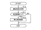
- FIG. 2 is a flowchart for determining the isobaric combustion mode.
- FIG. 3 is a block diagram of fuel injection control processing.
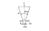
- FIG. 4 is a diagram showing the definition of the spray angle.
- FIG. 5 is a diagram showing a spray angle setting method.
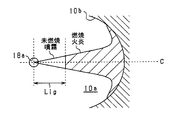
- FIG. 6 is a diagram illustrating a definition of a target moving distance.
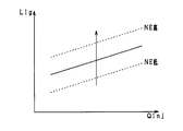
- FIG. 7 is a diagram illustrating a method for setting a target moving distance.
- FIG. 8 is a diagram illustrating a contraction coefficient setting method.
- FIG. 9 is a diagram illustrating a relationship between an injection rate and a heat generation rate.
- FIG. 10 is a diagram illustrating an injection rate setting method.
- FIG. 11 is a block diagram of a fuel injection control process according to the second embodiment.
- FIG. 12 is a diagram showing a method for setting a target equivalent ratio.
- the engine 10 shown in FIG. 1 is mounted on a vehicle as an in-vehicle main engine, and is a four-cycle engine including intake, compression, expansion, and exhaust strokes.
- an air flow meter 12 that detects the amount of intake air
- an intercooler 13 that cools intake air supercharged by a turbocharger 16 that will be described later
- a throttle valve device 14 Is provided.
- the throttle valve device 14 adjusts the opening degree of the throttle valve 14a by an actuator such as a DC motor.
- a combustion chamber 10 a of each cylinder of the engine 10 is connected to the downstream side of the throttle valve device 14 in the intake passage 11 via a surge tank 15.
- the combustion chamber 10 a is partitioned by a cylinder 10 b and a piston 17 of the engine 10.
- the engine 10 is provided with a fuel injection valve 18 having a tip projecting into the combustion chamber 10a.
- High pressure fuel (specifically, light oil) is supplied to the fuel injection valve 18 from a common rail 19 as a pressure accumulating container. Fuel is pumped from the fuel pump 20 to the common rail 19. In FIG. 1, only one cylinder is shown.
- the fuel injection valve 18 includes a needle and a body in which a plurality of circular injection holes for injecting fuel are formed at the tip, and the needle is accommodated therein. Between the inner surface of the body and the outer surface of the needle, an annular fuel passage that extends in the axial direction of the body and through which the fuel supplied from the common rail 19 passes is formed. A seating surface on which the tip of the needle is seated is formed on the inner surface of the body tip. In this configuration, when the needle is seated on the seating surface, the gap between the fuel passage and the injection hole is cut off, and fuel injection is stopped. On the other hand, the fuel passage and the injection hole are communicated with each other by separating the needle from the seating surface by the energization operation. As a result, the fuel in the fuel passage is directly supplied from the injection hole to the combustion chamber 10a.
- the fuel injection valve 18 is configured to freely control the injection rate.
- the fuel injection valve 18 is configured to be able to freely control the lift amount of the needle so as to freely control the injection rate.
- the intake port and the exhaust port of each cylinder of the engine 10 are opened and closed by the intake valve 21 and the exhaust valve 22, respectively.
- intake air cooled by the intercooler 13 by opening the intake valve 21 and external EGR gas described later are introduced into the combustion chamber 10a.
- fuel is injected from the fuel injection valve 18 into the combustion chamber 10a with intake air or the like introduced, the fuel self-ignites due to compression of the combustion chamber 10a, and energy is generated by combustion. This energy is taken out as rotational energy of the crankshaft 23 of the diesel engine 10 via the piston 17.
- the gas used for combustion is discharged as exhaust into the exhaust passage 24 by opening the exhaust valve 22.
- a crank angle sensor 25 that detects the rotation angle of the crankshaft 23 is provided in the vicinity of the crankshaft 23.
- the vehicle is provided with a turbocharger 16.
- the turbocharger 16 includes an intake air compressor 16a provided in the intake passage 11, an exhaust turbine 16b provided in the exhaust passage 24, and a rotating shaft 16c that connects these. Specifically, the exhaust turbine 16b is rotated by the energy of the exhaust gas flowing through the exhaust passage 24, and the rotational energy is transmitted to the intake compressor 16a via the rotary shaft 16c, and the intake air is compressed by the intake compressor 16a. That is, the intake air is supercharged by the turbocharger 16.
- the turbocharger 16 can adjust the supercharging pressure of intake air by an energization operation.
- a purification device 26 that purifies the exhaust gas is provided on the downstream side of the turbocharger 16 in the exhaust passage 24.
- Part of the exhaust discharged to the exhaust passage 24 is recirculated to the intake passage 11 via the EGR passage 27.
- the upstream side of the exhaust turbine 16 b in the exhaust passage 24 is connected to the surge tank 15 via the EGR passage 27.
- An EGR valve device 28 is provided in the EGR passage 27.
- the EGR valve device 28 adjusts the opening degree of the EGR valve 28a by an actuator such as a DC motor.
- a part of the exhaust discharged to the exhaust passage 24 is cooled by the EGR cooler 29 and then supplied to the surge tank 15 as external EGR gas.
- the ECU 30, which is an electronic control device that controls the engine system, is configured mainly by a microcomputer including a known CPU, ROM, RAM, and the like.
- the ECU 30 includes an intake pressure sensor 31, an intake air temperature sensor 32, an exhaust gas temperature sensor 33, an in-cylinder pressure sensor 34 as a pressure detection unit, a fuel pressure sensor 35, a water temperature sensor 36, an accelerator sensor 37, an air flow meter 12, and a crank angle sensor 25.
- the detected value is input.
- the intake pressure sensor 31 detects the gas pressure in the surge tank 15, and the intake temperature sensor 32 detects the gas temperature in the surge tank 15.
- the exhaust temperature sensor 33 detects the temperature of the exhaust discharged from the combustion chamber 10a, and the in-cylinder pressure sensor 34 detects an in-cylinder pressure that is a pressure in the combustion chamber 10a.
- the fuel pressure sensor 35 detects the fuel pressure in the common rail 19, and the water temperature sensor 36 detects the cooling water temperature of the engine 10.
- the accelerator sensor 37 detects the accelerator operation amount of the accelerator operation member of the driver, and specifically detects the depression amount of the accelerator pedal.
- the ECU 30 includes an engine including fuel injection control of the fuel injection valve 18, drive control of the fuel pump 20, drive control of the EGR valve device 28, and supercharging pressure control by the turbocharger 16 based on the detection values of the various sensors described above. 10 combustion control is performed.
- the ECU 30 performs fuel injection control for realizing isobaric combustion in the high load region of the engine 10. Isobaric combustion is such that the peak of in-cylinder pressure after the start of combustion is kept substantially constant.
- FIG. 2 shows the procedure of the fuel injection control process according to this embodiment. This process is repeatedly executed by the ECU 30 at a predetermined cycle, for example.
- step S10 the operating state of the engine 10 is acquired.
- the operating state includes the engine speed NE, the accelerator operation amount Acc detected by the accelerator sensor 37, the gas pressure Pim detected by the intake pressure sensor 31, and the gas temperature detected by the intake temperature sensor 32. Tim is included.
- the engine speed NE may be calculated based on the detected value of the crank angle sensor 25.
- step S11 it is determined whether or not the fuel injection control is performed in the isobaric combustion mode based on the operating state of the engine 10 acquired in step S10. Specifically, for example, it is determined whether or not the required output of the engine 10 ascertained from the operating state is equal to or higher than a predetermined output, or whether or not the required output of the engine 10 is a maximum output determined from the engine rotational speed NE. .
- step S11 When an affirmative determination is made in step S11, the process proceeds to step S12 to perform fuel injection control in the isobaric combustion mode.
- FIG. 3 shows a block diagram of the fuel injection control process in the isobaric combustion mode. The processing of each unit shown in FIG. 3 is executed by the ECU 30.
- the injection setting unit 40 sets the fuel injection amount Qinj, the injection start timing tinj of the fuel injection valve 18 and the fuel injection pressure Pinj of the fuel injection valve 18 based on the accelerator operation amount Acc and the engine speed NE.
- the fuel injection amount Qinj is a fuel injection amount that contributes to the output torque generation of the engine 10 required per combustion cycle.
- the gas density estimation unit 41 calculates the gas density ⁇ a in the combustion chamber 10a at the injection start timing tinj based on the gas pressure Pim and the gas temperature Tim. Specifically, the gas density ⁇ a is calculated based on the following equations (eq1) and (eq2).
- Mcyl represents the total gas amount [mg] sucked into the combustion chamber 10a in the intake stroke
- V (tinj) represents the volume [L] of the combustion chamber 10a at the injection start timing tinj [deg].
- R represents a gas constant [J / K / mol]
- Mail represents the molecular weight [mg / mol] of air
- V (tcls) represents the intake stroke end timing [deg], that is, The volume of the combustion chamber 10a at the fully closed timing of the intake valve 21 is shown.
- the volume V (tcls) is calculated based on the design value of the cylinder 10b and the fully closed timing of the intake valve 21, and the volume V (tinj) is calculated based on the design value of the cylinder 10b and the injection start timing tinj.
- the unit of Pim assumes [kPa]
- the unit of Tim assumes [K].
- the molecular weight considering the gas composition may be used instead of the molecular weight of air.
- the angle calculation unit 42 is based on the injection pressure Pinj set by the injection setting unit 40 and the gas density ⁇ a estimated by the gas density estimation unit 41, and the spray angle ⁇ sp of the fuel spray injected from the fuel injection valve 18. Is calculated.
- the spray angle ⁇ sp is defined as the spread angle of the fuel spray “A” with respect to the injection direction “C” from the injection hole 18 a of the fuel injection valve 18.
- the spray angle ⁇ sp is calculated based on the injection pressure Pinj and the gas density ⁇ a. Specifically, the spray angle ⁇ sp is calculated to be larger as the injection pressure Pinj is higher. This is because the higher the injection pressure Pinj, the larger the average momentum of the fuel injected from the nozzle hole 18a, and the larger the spray angle ⁇ sp. Further, the spray angle ⁇ sp is calculated to be larger as the gas density ⁇ a is larger. This is because the higher the gas density ⁇ a, the stronger the degree of diffusion of the fuel injected from the nozzle hole 18a against the gas in the combustion chamber 10a. Incidentally, the spray angle ⁇ sp may be calculated based on a map or an empirical formula in which the injection pressure Pinj, the gas density ⁇ a, and the spray angle ⁇ sp are related.
- the delay time setting unit 43 sets the ignition delay time td.
- the ignition delay time td is defined as the time from the injection start timing tinj until the injected fuel spray starts self-igniting.
- the ignition delay time td may be set to a constant value, or may be variably set based on a map or an empirical formula in which the operating state of the engine 10 and the ignition delay time td are related.
- the target value setting unit 44 sets the target moving distance Lig based on the fuel injection amount Qinj set by the injection setting unit 40 and the engine rotational speed NE.
- the target moving distance Lig is the distance between the tip of the fuel spray in the injection direction C and the injection hole 18a at the timing when the ignition delay time td has elapsed from the injection start timing tinj.
- FIG. 6 shows an unburned spray in which the fuel spray injected from the nozzle hole 18a has not yet burned, and a flame generated by the combustion of the injected fuel spray.
- the target moving distance Lig is a spray characteristic value set in order to reduce smoke generated by fuel combustion. That is, if the moving distance of the fuel spray from the injection hole 18a at the timing when the ignition delay time td elapses from the injection start timing tinj, mixing of the fuel spray and the intake air in the combustion chamber 10a may be insufficient. In this case, not only the smoke generated by the combustion of fuel at the initial stage of injection increases, but also the smoke generated by the combustion of fuel after the initial stage of injection increases.
- the moving distance from the nozzle hole 18 a at the tip of the fuel spray at the timing when the ignition delay time td has elapsed from the injection start timing tinj is set to an appropriate value according to the operating state of the engine 10. Thereby, the mixing degree of the fuel spray and the intake air at the self-ignition start position can be set to an appropriate mixing degree that can reduce smoke.
- the mixing degree has a positive correlation with the moving distance.
- the target moving distance Lig is set based on the fuel injection amount Qinj and the engine speed NE. Specifically, the target movement distance Lig is set larger as the fuel injection amount Qinj is larger or the engine speed NE is higher. This is because the larger the fuel injection amount Qinj or the higher the engine rotational speed NE, the larger the space in the injection direction “C” necessary to promote the mixing of the fuel spray and the intake air.
- the target moving distance Lig may be calculated based on a map or an empirical formula in which the fuel injection amount Qinj, the engine rotational speed NE, and the target moving distance Lig are related.
- the speed setting unit 45 calculates the gas density ⁇ a estimated by the gas density estimation unit 41, the ignition delay time td set by the delay time setting unit 43, the target moving distance Lig set by the target value setting unit 44, and angle calculation. Based on the spray angle ⁇ sp calculated by the unit 42, the injection speed Vini of the fuel spray from the nozzle hole 18a at the injection start timing tinj is set. In the present embodiment, the injection speed Vini is set based on the following equation (eq3).
- FIG. 8 is a map showing the relationship between the injection pressure Pinj and the contraction coefficient “c”, and is set in advance based on experiments or the like. As shown in FIG. 8, the higher the injection pressure Pinj, the smaller the contraction coefficient “c”.
- the above equation (eq3) is "Study on the reach of diesel engine fuel spray Yutaro Waguri and three others, Transactions of the Japan Society of Mechanical Engineers, 1959, Vol. 25, No. 156, pp. 820-826"
- the injection speed Vini can be expressed by the following equation (eq4) using the differential pressure ⁇ P between the injection hole 18a in the combustion chamber 10a and the position away from the injection hole 18a by the target movement distance Lig.
- the target moving distance Lig can be expressed as in the following equation (eq5).
- the first injection calculating unit 46 calculates a starting injection rate Qst that is an injection rate at the injection start timing tinj based on the injection speed Vini set by the speed setting unit 45.
- the starting injection rate Qst is calculated based on the following equation (eq7).
- Nh indicates the number of injection holes 18a of the fuel injection valve 18
- S indicates the total injection hole area of the fuel injection valve 18.
- the injection rate is the volume of fuel injected from the fuel injection valve 18 per unit time.
- the injection rate is the mass of fuel injected from the fuel injection valve 18 per unit time
- the right side of the above equation (eq7) may be multiplied by the fuel density ⁇ f.
- the first heat estimation unit 47 calculates the start-time heat generation rate Jst at the self-ignition start timing “tinj + td” based on the start-time injection rate Qst calculated by the first injection calculation unit 46. Specifically, the starting heat release rate Jst is calculated based on the following equation (eq8).
- FIG. 9 shows the start-time injection rate Qst at the injection start timing tinj and the start-time heat release rate Jst estimated based on the start-time injection rate Qst.
- the second heat estimation unit 48 calculates a rate of increase ⁇ HRR of the heat generation rate after the self-ignition start timing that maximizes the indicated mean effective pressure of the engine 10 on condition that the in-cylinder pressure is set to the threshold value Pmax or less.
- the threshold value Pmax is set to a value equal to or lower than the allowable upper limit value of the in-cylinder pressure that can maintain the reliability of the engine 10, for example.
- the second heat estimation unit 48 includes a heat generation rate estimation unit, an in-cylinder pressure estimation unit, and a thermal gradient calculation unit as a processing unit for calculating the ascending speed ⁇ HRR.
- the heat generation rate estimation unit starts from the self-ignition start timing “tinj + td” as shown in FIG.
- the heat generation rate for each period in the period until the heat generation rate reaches the total generation rate Jq is estimated.
- the total occurrence rate Jq is calculated based on the following equation (eq9) with the fuel injection amount Qinj as an input.
- the in-cylinder pressure estimation unit estimates the in-cylinder pressure Pcyl for each specified period based on the heat generation rate estimated by the heat generation rate estimation unit.
- the specified time is a period from the self-ignition start timing until the integrated value of the heat generation rate starting from this timing reaches the total generation rate Jq.
- the in-cylinder pressure Pcyl ( ⁇ r) at a certain crank angle ⁇ r may be calculated based on the function f shown in the following equation (eq10).
- ⁇ represents the crank angle interval for calculating the in-cylinder pressure
- V ( ⁇ r) represents the volume of the combustion chamber 10a at a certain crank angle ⁇ r
- HRR ( ⁇ r) represents the heat at a certain crank angle ⁇ r. Indicates the incidence.
- the function f shown in the above equation (eq10) is obtained by modifying the following equation (eq11) derived from the thermodynamic equation and the gas equation of state.
- Cv represents a constant volume specific heat [J / mol / K]
- R represents a gas constant [J / K / mol].
- the initial value of the in-cylinder pressure Pcyl that is, the in-cylinder pressure Pcyl immediately before the self-ignition timing may be set to, for example, the gas pressure Pim.
- the thermal gradient calculation unit sets the in-cylinder pressure Pcyl at a timing when the heat generation rate becomes the total generation rate Jq when the temporary setting value ⁇ Hm of the rising speed is set to various values, and the average illustrated
- the provisional set value ⁇ Hm that maximizes the effective pressure is calculated as the rising speed ⁇ HRR.
- the second injection calculation unit 49 calculates the rate of increase ⁇ inj of the injection rate after the start time injection rate Qst based on the start time injection rate Qst, the start time heat generation rate Jst, the injection start timing tinj, and the ignition delay time td. .
- the 2nd heat estimation part 48 and the 2nd injection calculation part 49 comprise a raise setting part.
- FIG. 10 (a) shows the transition of the in-cylinder pressure
- FIG. 10 (b) shows the transition of the heat generation rate
- FIG. 10 (c) shows the transition of the injection rate.
- the in-cylinder pressure waveform when the isobaric combustion is performed is indicated by a solid line
- the in-cylinder pressure waveform when the fuel is not burned in the combustion chamber 10a is indicated by a broken line.
- each waveform is shown with the ignition delay time td being zero.
- the heat generation rate Jmed at the specified timing tmed after the self-ignition start timing t1 is calculated based on the start-time heat generation rate Jst and the heat generation rate increase rate ⁇ HRR. Then, the calculated heat generation rate Jmed is converted into the injection rate Qmed using the calorific value Ju when the fuel per unit volume burns. Then, the injection rate increase rate ⁇ inj is calculated based on the starting injection rate Qst, the converted injection rate Qmed, the injection start timing tinj, and the specified timing tmed.
- the command injection rate includes a start injection rate Qst and a rising injection rate that increases at a constant rising speed ⁇ inj after the injection start timing tinj.
- the injection rate at the injection end timing is the maximum injection rate in one combustion cycle.
- FIG. 10C shows an example in which the period during which the ascending injection rate is set straddles TDC.
- the ECU 30 functions as an injection control unit that energizes the fuel injection valve 18 so as to control the injection rate of the fuel injection valve 18 to the command injection rate.
- the target moving distance Lig was set based on the operating state of the engine 10. Then, the injection rate Qst at the start for setting the moving distance from the injection hole 18a at the tip of the fuel spray at the timing when the ignition delay time td has elapsed from the injection start timing tinj is set. As a result, the fuel spray injected according to the start injection rate Qst and the fuel spray injected according to the injection rate following the start injection rate Qst can be sufficiently mixed with the intake air, and the smoke generated by the combustion of the fuel can be reduced. Can be reduced.
- the smoke generated by the combustion of the fuel spray injected according to the start injection rate Qst can be reduced, the injection rate after the start injection rate Qst can be increased, and the output torque of the engine 10 can be improved.
- the injection speed Vini was used to calculate the starting injection rate Qst. Thereby, in order to reduce smoke, the fuel injection control which considered the momentum of the fuel spray in self-ignition start timing can be performed.
- the injection rate increasing speed ⁇ inj after the start injection rate Qst that maximizes the indicated mean effective pressure of the engine 10 is set. Thereby, the output torque of the engine 10 can be improved without improving the strength of the engine.
- the injection rate is set using the target equivalent ratio ⁇ ig instead of the target moving distance Lig.
- the target equivalent ratio ⁇ ig is a target value of the equivalent ratio of the fuel spray and the intake air at the self-ignition start position of the fuel spray injected from the fuel injection valve 18 in the combustion chamber 10a.
- FIG. 11 shows a block diagram of the fuel injection control process in the isobaric combustion mode according to the present embodiment.
- the processing of each unit shown in FIG. 11 is executed by the ECU 30.
- the same processes as those shown in FIG. 3 are given the same reference numerals for the sake of convenience.
- the target value setting unit 50 sets the target equivalent ratio ⁇ ig based on the fuel injection amount Qinj and the engine rotation speed NE.
- the target equivalent ratio ⁇ ig is a spray characteristic value set to reduce smoke generated by the combustion of fuel.
- the target equivalent ratio ⁇ ig is set based on the fuel injection amount Qinj and the engine speed NE. Specifically, the target equivalence ratio ⁇ ig is set larger as the fuel injection amount Qinj is larger or the engine speed NE is lower.
- the speed setting unit 51 Based on the gas density ⁇ a, the ignition delay time td, the spray angle ⁇ sp, and the target equivalence ratio ⁇ ig set by the target value setting unit 50, the speed setting unit 51 performs fuel spray from the nozzle hole 18a at the injection start timing tinj.
- the injection speed Vini is set. In the present embodiment, the injection speed Vini is set based on the following equation (eq12).
- ⁇ th represents the theoretical equivalent ratio and is the reciprocal of the oxygen excess rate.
- the command injection rate is set by the same processing as in the first embodiment.
- the target equivalent ratio ⁇ ig is set based on the operating state of the engine 10. Then, an injection rate Qst at the start for setting the actual equivalent ratio at the self-ignition start position to be the target equivalent ratio ⁇ ig was set. Thereby, the same effects as those of the first embodiment can be obtained.
- the injection rate increase mode after the start injection rate Qst is the injection rate waveform that increases at a constant increase rate, but is not limited thereto.
- the increase rate of the injection rate after the starting injection rate Qst may be a waveform that increases stepwise or a waveform that increases in an arc shape. Even in this case, since the starting injection rate Qst is set to an appropriate value that can reduce smoke, smoke can be reduced.
- only one of the fuel injection amount Qinj and the engine rotation speed NE may be used for setting the target movement distance Lig.
- only one of the fuel injection amount Qinj and the engine rotational speed NE may be used for setting the target equivalent ratio ⁇ ig.
- the fuel injection valve that can freely set the injection rate is not limited to that described in the first embodiment.
- a fuel injection valve with a pressure increasing mechanism may be used.
Landscapes
- Engineering & Computer Science (AREA)
- Chemical & Material Sciences (AREA)
- Combustion & Propulsion (AREA)
- Mechanical Engineering (AREA)
- General Engineering & Computer Science (AREA)
- Electrical Control Of Air Or Fuel Supplied To Internal-Combustion Engine (AREA)
- Fuel-Injection Apparatus (AREA)
- Combined Controls Of Internal Combustion Engines (AREA)
Abstract
燃焼室内での自着火開始位置における燃料噴霧及び吸気の混合度合いと相関を有するパラメータを噴霧特性値と定義する。噴霧特性値は、例えば、燃料噴射弁の噴射開始タイミングから着火遅れ時間が経過するタイミングにおける燃料噴霧の先端と燃料噴射弁の噴孔との距離である。制御装置は、エンジンの運転状態に基づいて、噴霧特性値の目標値を設定する。制御装置は、実際の噴霧特性値を目標値とすべく燃料噴射弁の噴射開始タイミングにおける開始時噴射率を設定し、燃料噴射弁の噴射率を開始時噴射率から徐々に増加させる噴射制御を行う。
Description
本出願は、2015年9月1日に出願された日本特許出願番号2015-171804号に基づくもので、ここにその記載内容を援用する。
本開示は、ディーゼルエンジンに適用される燃料噴射制御装置に関する。
ディーゼルエンジンは、燃料噴射弁から噴射された燃料を燃焼室の圧縮により自着火させるため、ガソリンエンジンに比べて圧縮比が高く、燃料の燃焼により発生する燃焼室内の筒内圧のピークが高くなる。筒内圧のピークがその許容上限値を超えると、エンジンの信頼性が低下する懸念がある。このため、エンジンの強度を向上させることにより許容上限値を高くすることも考えられる。しかしながら、エンジンの強度を向上させると、エンジンの重量及びコストが増加する懸念がある。
特許文献1に開示されるように、燃料噴射弁の燃料噴射開始直後から噴射率を徐々に増加させるように噴射制御を行う燃料噴射装置が知られている。これにより、筒内圧のピークを低下させる。
しかし、特許文献1に記載された燃料噴射装置においては、燃料噴射弁の噴射初期に噴射された燃料の運動量が低いと、噴射燃料と吸気との混合が不十分となるおそれがある。この場合、燃料の燃焼により発生するスモークが増加するおそれがある。
本開示は、ディーゼルエンジンにおいて発生するスモークを低減できる燃料噴射制御装置を提供することを目的とする。
本開示の一態様によれば、燃料噴射制御装置は、燃焼室内に燃料噴霧を直接噴射する燃料噴射弁を備えるディーゼルエンジンに適用され、前記燃焼室内での自着火開始位置における前記燃料噴霧及び吸気の混合度合いと相関を有するパラメータが噴霧特性値と定義されており、前記エンジンの運転状態に基づいて、前記噴霧特性値の目標値を設定する目標値設定部と、実際の前記噴霧特性値を前記目標値とすべく前記燃料噴射弁の噴射開始タイミングにおける開始時噴射率を設定する噴射率設定部と、前記燃料噴射弁の噴射率を前記開始時噴射率から徐々に増加させる噴射率時系列を含む指令噴射率に実際の噴射率を制御する噴射制御を行う噴射制御部と、を備える。
燃料噴射弁から噴射された燃料噴霧と吸気との混合が不十分なまま燃料噴霧が自着火し始めると、燃料の燃焼により発生するスモークが増加する。ここで、燃焼室内での自着火開始位置における燃料噴霧及び吸気の混合度合いと相関を有するパラメータを噴霧特性値と定義する。噴霧特性値を、エンジンの運転状態に応じた適正な値とすることにより、燃料の燃焼により発生するスモークを低減することができる。
本開示の一態様では、エンジンの運転状態に基づいて、噴霧特性値の目標値を設定し、実際の噴霧特性値を目標値とすべく燃料噴射弁の噴射開始タイミングにおける開始時噴射率を設定する。これにより、開始時噴射率に従って噴射された燃料噴霧、及び開始時噴射率に続く噴射率に従って噴射された燃料噴霧を吸気と十分に混合させることができ、燃料の燃焼により発生するスモークを低減することができる。
本開示についての上記目的およびその他の目的、特徴や利点は、添付の図面を参照しながら下記の詳細な記述により、より明確になる。
図1は、第1実施形態に係る車載エンジンシステムの全体構成図。
図2は、等圧燃焼モードを判定するフローチャート。
図3は、燃料噴射制御処理のブロック図。
図4は、噴霧角の定義を示す図。
図5は、噴霧角の設定手法を示す図。
図6は、目標移動距離の定義を示す図。
図7は、目標移動距離の設定手法を示す図。
図8は、収縮係数の設定手法を示す図。
図9は、噴射率と熱発生率との関係を示す図。
図10は、噴射率の設定手法を示す図。
図11は、第2実施形態に係る燃料噴射制御処理のブロック図。
図12は、目標当量比の設定手法を示す図。
(第1実施形態)
以下、本開示に係る燃料噴射制御装置をコモンレール式燃料噴射装置が備えられる多気筒ディーゼルエンジンに適用した第1実施形態について、図面を参照しつつ説明する。
以下、本開示に係る燃料噴射制御装置をコモンレール式燃料噴射装置が備えられる多気筒ディーゼルエンジンに適用した第1実施形態について、図面を参照しつつ説明する。
本実施形態において、図1に示すエンジン10は、車載主機として車両に搭載されており、吸気、圧縮、膨張及び排気行程からなる4サイクルエンジンである。エンジン10の吸気通路11には、上流側から順に、吸入される空気量を検出するエアフローメータ12、後述するターボチャージャ16によって過給された吸気を冷却するインタークーラ13、更にはスロットルバルブ装置14が設けられている。スロットルバルブ装置14は、DCモータ等のアクチュエータにより、スロットルバルブ14aの開度を調節する。
吸気通路11においてスロットルバルブ装置14の下流側には、サージタンク15を介してエンジン10の各気筒の燃焼室10aが接続されている。燃焼室10aは、エンジン10のシリンダ10b及びピストン17にて区画されている。エンジン10には、燃焼室10a内に先端部が突出した燃料噴射弁18が設けられている。燃料噴射弁18には、蓄圧容器としてのコモンレール19から高圧の燃料(具体的には軽油)が供給される。コモンレール19には、燃料ポンプ20から燃料が圧送される。なお、図1では、1つの気筒のみを示している。
燃料噴射弁18は、ニードルと、燃料を噴射する円形の噴孔が先端部に複数形成され、内部にニードルが収容されるボディとを備えている。ボディの内面とニードルの外面との間には、ボディの軸方向に延びてかつコモンレール19から供給された燃料が通過する環状の燃料通路が形成されている。ボディ先端部の内面には、ニードルの先端部が着座する着座面が形成されている。この構成において、ニードルを着座面に着座させることにより、上記燃料通路と噴孔との間が遮断され、燃料噴射が停止される。一方、通電操作によってニードルを着座面から離座させることにより、上記燃料通路と噴孔との間が連通される。その結果、燃料通路の燃料は、噴孔から燃焼室10aへと直接噴射供給される。
燃料噴射弁18は、噴射率を自在に制御できる構成とされている。本実施形態において、燃料噴射弁18は、噴射率を自在に制御すべく、ニードルのリフト量を自在に制御できる構成とされている。
エンジン10の各気筒の吸気ポート及び排気ポートのそれぞれは、吸気バルブ21及び排気バルブ22のそれぞれにより開閉される。ここでは、吸気バルブ21の開弁によってインタークーラ13で冷却された吸気や、後述する外部EGRガスが燃焼室10aに導入される。吸気等が導入された状態で燃料噴射弁18から燃焼室10aに燃料が噴射されると、燃焼室10aの圧縮によって燃料が自己着火し、燃焼によってエネルギが発生する。このエネルギは、ピストン17を介して、ディーゼルエンジン10のクランク軸23の回転エネルギとして取り出される。燃焼に供されたガスは、排気バルブ22の開弁によって、排気通路24に排気として排出される。なお、クランク軸23付近には、クランク軸23の回転角度を検出するクランク角度センサ25が設けられている。
車両には、ターボチャージャ16が設けられている。ターボチャージャ16は、吸気通路11に設けられた吸気コンプレッサ16aと、排気通路24に設けられた排気タービン16bと、これらを連結する回転軸16cとを備えている。詳しくは、排気通路24を流れる排気のエネルギによって排気タービン16bが回転し、その回転エネルギが回転軸16cを介して吸気コンプレッサ16aに伝達され、吸気コンプレッサ16aによって吸気が圧縮される。すなわち、ターボチャージャ16によって吸気が過給される。なお本実施形態では、ターボチャージャ16として、通電操作によって吸気の過給圧を調節可能なものを想定している。
なお、排気通路24のうちターボチャージャ16の下流側には、排気を浄化する浄化装置26が設けられている。
排気通路24に排出された排気の一部は、EGR通路27を介して吸気通路11に還流される。詳しくは、排気通路24のうち排気タービン16bの上流側は、EGR通路27を介してサージタンク15に接続されている。EGR通路27には、EGRバルブ装置28が設けられている。EGRバルブ装置28は、DCモータ等のアクチュエータにより、EGRバルブ28aの開度を調節する。EGRバルブ28aの開度に応じて、排気通路24に排出された排気の一部が、EGRクーラ29によって冷却された後に外部EGRガスとしてサージタンク15に供給される。
エンジンシステムを制御対象とする電子制御装置であるECU30は、周知のCPU、ROM、RAM等よりなるマイクロコンピュータを主体として構成されている。ECU30には、吸気圧センサ31、吸気温センサ32、排気温センサ33、圧力検出部としての筒内圧センサ34、燃圧センサ35、水温センサ36、アクセルセンサ37、エアフローメータ12、及びクランク角度センサ25の検出値が入力される。吸気圧センサ31は、サージタンク15内のガス圧力を検出し、吸気温センサ32は、サージタンク15内のガス温度を検出する。排気温センサ33は、燃焼室10aから排出された排気の温度を検出し、筒内圧センサ34は、燃焼室10a内の圧力である筒内圧を検出する。燃圧センサ35は、コモンレール19内の燃料圧力を検出し、水温センサ36は、エンジン10の冷却水温を検出する。アクセルセンサ37は、ドライバのアクセル操作部材のアクセル操作量を検出し、具体的にはアクセルペダルの踏み込み量を検出する。
ECU30は、上述した各種センサの検出値に基づいて、燃料噴射弁18の燃料噴射制御、燃料ポンプ20の駆動制御、EGRバルブ装置28の駆動制御、及びターボチャージャ16による過給圧制御を含むエンジン10の燃焼制御を行う。
特にECU30は、エンジン10の高負荷領域において、等圧燃焼を実現するための燃料噴射制御を行う。等圧燃焼は、燃焼開始後における筒内圧のピークを略一定に保つようにしたものである。
図2に、本実施形態に係る燃料噴射制御処理の手順を示す。この処理は、ECU30によって例えば所定周期で繰り返し実行される。
この一連の処理では、まずステップS10において、エンジン10の運転状態を取得する。本実施形態において、運転状態には、エンジン回転速度NE、アクセルセンサ37によって検出されたアクセル操作量Acc、吸気圧センサ31によって検出されたガス圧力Pim、及び吸気温センサ32によって検出されたガス温度Timが含まれる。なお、エンジン回転速度NEは、クランク角度センサ25の検出値に基づいて算出されればよい。
続くステップS11では、ステップS10で取得したエンジン10の運転状態に基づいて、等圧燃焼モードで燃料噴射制御を行う状況であるか否かを判定する。具体的には例えば、運転状態から把握されるエンジン10の要求出力が所定出力以上であるか否か、又はエンジン10の要求出力がエンジン回転速度NEから定まる最高出力であるか否かを判定する。
ステップS11で肯定判定した場合には、ステップS12に進み、等圧燃焼モードで燃料噴射制御を行う。
図3に、等圧燃焼モードにおける燃料噴射制御処理のブロック図を示す。図3に示す各部の処理は、ECU30によって実行される。
噴射設定部40は、アクセル操作量Acc及びエンジン回転速度NEに基づいて、燃料噴射量Qinj、燃料噴射弁18の噴射開始タイミングtinj、及び燃料噴射弁18の燃料噴射圧Pinjを設定する。ここで、燃料噴射量Qinjは、1燃焼サイクルあたりに要求されるエンジン10の出力トルク生成に寄与する燃料噴射量である。
ガス密度推定部41は、ガス圧力Pim及びガス温度Timに基づいて、噴射開始タイミングtinjにおける燃焼室10a内のガス密度ρaを算出する。詳しくは、下式(eq1),(eq2)に基づいて、ガス密度ρaを算出する。


ちなみに、EGRガスの再循環を行っている場合等は、空気の分子量に代えてガスの組成を考慮した分子量を用いてもよい。
角度算出部42は、噴射設定部40で設定された噴射圧Pinjと、ガス密度推定部41で推定されたガス密度ρaとに基づいて、燃料噴射弁18から噴射された燃料噴霧の噴霧角θspを算出する。本実施形態では、図4に示すように、噴霧角θspは、燃料噴射弁18の噴孔18aからの噴射方向「C」に対する燃料噴霧「A」の広がり角として定義される。
本実施形態では、図5に示すように、噴射圧Pinj及びガス密度ρaに基づいて、噴霧角θspを算出する。詳しくは、噴射圧Pinjが高いほど、噴霧角θspを大きく算出する。これは、噴射圧Pinjが高いほど、噴孔18aから噴射される燃料の平均運動量が大きくなり、噴霧角θspが大きくなるためである。また、ガス密度ρaが大きいほど、噴霧角θspを大きく算出する。これは、ガス密度ρaが大きいほど、噴孔18aから噴射された燃料が燃焼室10a内のガスに当たって拡散する度合いが強くなるためである。ちなみに、噴霧角θspは、噴射圧Pinj及びガス密度ρaと噴霧角θspとが関係付けられたマップ又は実験式に基づいて算出されればよい。
遅れ時間設定部43は、着火遅れ時間tdを設定する。本実施形態において、着火遅れ時間tdは、噴射開始タイミングtinjから、噴射された燃料噴霧が自着火し始めるまでの時間として定義される。なお、着火遅れ時間tdは、一定値に設定されてもよいし、エンジン10の運転状態及び着火遅れ時間tdが関係付けられたマップ又は実験式に基づいて可変設定されてもよい。
目標値設定部44は、噴射設定部40で設定された燃料噴射量Qinjと、エンジン回転速度NEとに基づいて、目標移動距離Ligを設定する。本実施形態において、目標移動距離Ligは、図6に示すように、噴射開始タイミングtinjから着火遅れ時間tdが経過したタイミングにおける燃料噴霧の噴射方向Cの先端と、噴孔18aとの間の距離として定義される。なお図6に、噴孔18aから噴射された燃料噴霧が未だ燃焼していない未燃焼噴霧と、噴射された燃料噴霧の燃焼により生じた火炎とを示す。
目標移動距離Ligは、燃料の燃焼により発生するスモークを低減するために設定される噴霧特性値である。つまり、噴射開始タイミングtinjから着火遅れ時間tdが経過するタイミングにおける燃料噴霧の噴孔18aからの移動距離が短いと、燃焼室10a内における燃料噴霧と吸気との混合が不十分となり得る。この場合、噴射初期の燃料の燃焼により発生するスモークが増加するのみならず、噴射初期以降の燃料の燃焼により発生するスモークも増加する。ここで、噴射開始タイミングtinjから着火遅れ時間tdが経過したタイミングにおける燃料噴霧先端の噴孔18aからの移動距離を、エンジン10の運転状態に応じた適正な値とする。これにより、自着火開始位置における燃料噴霧及び吸気の混合度合いを、スモークを低減できる適正な混合度合いとすることができる。上記混合度合いは、上記移動距離と正の相関を有する。
本実施形態では、図7に示すように、燃料噴射量Qinj及びエンジン回転速度NEに基づいて、目標移動距離Ligを設定する。詳しくは、燃料噴射量Qinjが多かったり、エンジン回転速度NEが高かったりするほど、目標移動距離Ligを大きく設定する。これは、燃料噴射量Qinjが多かったり、エンジン回転速度NEが高かったりするほど、燃料噴霧と吸気との混合を促進させるために必要な噴射方向「C」の空間が大きくなるためである。ちなみに、目標移動距離Ligは、燃料噴射量Qinj及びエンジン回転速度NEと目標移動距離Ligとが関係付けられたマップ又は実験式に基づいて算出されればよい。
速度設定部45は、ガス密度推定部41で推定されたガス密度ρa、遅れ時間設定部43で設定された着火遅れ時間td、目標値設定部44で設定された目標移動距離Lig、及び角度算出部42で算出された噴霧角θspに基づいて、噴射開始タイミングtinjにおける噴孔18aからの燃料噴霧の噴射速度Viniを設定する。本実施形態では、下式(eq3)に基づいて噴射速度Viniを設定する。

ちなみに、上式(eq3)は、「ディーゼル機関燃料噴霧の到達距離に関する研究 和栗雄太郎、他3名、日本機械学会論文集、1959年、第25巻、第156号、p.820-826」の記載事項に基づいて導かれる。詳しくは、燃焼室10a内における噴孔18aと、噴孔18aから目標移動距離Lig離れた位置との差圧ΔPを用いて、噴射速度Viniを下式(eq4)のように表すことができる。



第1噴射算出部46は、速度設定部45で設定された噴射速度Viniに基づいて、噴射開始タイミングtinjにおける噴射率である開始時噴射率Qstを算出する。本実施形態では、下式(eq7)に基づいて、開始時噴射率Qstを算出する。
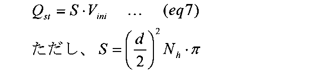
ちなみに本実施形態では、噴射率を、燃料噴射弁18から単位時間あたりに噴射される燃料の体積とした。噴射率を、燃料噴射弁18から単位時間あたりに噴射される燃料の質量とする場合、上式(eq7)の右辺に燃料密度ρfを乗算すればよい。
第1熱推定部47は、第1噴射算出部46で算出された開始時噴射率Qstに基づいて、自着火開始タイミング「tinj+td」における開始時熱発生率Jstを算出する。詳しくは、下式(eq8)に基づいて、開始時熱発生率Jstを算出する。

第2熱推定部48は、筒内圧をその閾値Pmax以下にすることを条件として、エンジン10の図示平均有効圧を最大とする自着火開始タイミング以降における熱発生率の上昇速度θHRRを算出する。なお、上記閾値Pmaxは、例えば、エンジン10の信頼性を維持可能な筒内圧の許容上限値以下の値に設定される。
本実施形態において、第2熱推定部48は、上昇速度θHRRを算出するための処理部として、熱発生率推定部と、筒内圧推定部と、熱勾配算出部とを含む。
熱発生率推定部は、開始時熱発生率Jstと、熱発生率の上昇速度の仮設定値θHmとに基づいて、図9(b)に示すように、自着火開始タイミング「tinj+td」から、熱発生率が総発生率Jqに到達するまでの期間における都度の熱発生率を推定する。ここで、総発生率Jqは、燃料噴射量Qinjを入力として、下式(eq9)に基づいて算出される。



熱勾配算出部は、上昇速度の仮設定値θHmを様々な値に設定した場合において、熱発生率が総発生率Jqとなるタイミングにおける筒内圧Pcylが閾値Pmax以下となって、かつ、図示平均有効圧が最大となる仮設定値θHmを上昇速度θHRRとして算出する。
第2噴射算出部49は、開始時噴射率Qst、開始時熱発生率Jst、噴射開始タイミングtinj及び着火遅れ時間tdに基づいて、開始時噴射率Qst以降における噴射率の上昇速度θinjを算出する。本実施形態において、第2熱推定部48及び第2噴射算出部49が上昇設定部を構成する。以下、図10を用いて、上昇速度θinjの算出手法について説明する。ここで、図10(a)は筒内圧の推移を示し、図10(b)は熱発生率の推移を示し、図10(c)は噴射率の推移を示す。なお図10(a)では、等圧燃焼が実施される場合の筒内圧波形を実線にて示し、燃焼室10a内で燃料の燃焼が行われない場合の筒内圧波形を破線にて示す。また図10では、便宜上、着火遅れ時間tdを0として各波形を記載している。
図10に示すように、自着火開始タイミングt1よりも後の規定タイミングtmedにおける熱発生率Jmedを、開始時熱発生率Jst及び熱発生率の上昇速度θHRRに基づいて算出する。そして、単位体積あたりの燃料が燃焼した時の発熱量Juを用いて、算出した熱発生率Jmedを噴射率Qmedに換算する。そして、開始時噴射率Qst、換算した噴射率Qmed、噴射開始タイミングtinj、及び規定タイミングtmedに基づいて、噴射率の上昇速度θinjを算出する。
上述した手法で算出された開始時噴射率Qst及び噴射率の上昇速度θinjに基づいて、図10(c)に示すような指令噴射率の時系列が設定される。指令噴射率は、開始時噴射率Qstと、噴射開始タイミングtinj以降において一定の上昇速度θinjで上昇する上昇噴射率とからなる。上昇噴射率のうち噴射終了タイミングの噴射率は、1燃焼サイクルにおいて最大の噴射率となる。図10(c)では、上昇噴射率が設定される期間がTDCを跨いでいる例を示した。ECU30は、燃料噴射弁18の噴射率を上記指令噴射率に制御するように燃料噴射弁18と通電操作する噴射制御部として機能する。
以上説明した本実施形態によれば、以下の効果を奏することができる。
エンジン10の運転状態に基づいて、目標移動距離Ligを設定した。そして、噴射開始タイミングtinjから着火遅れ時間tdが経過したタイミングにおける燃料噴霧先端の噴孔18aからの移動距離を目標移動距離Ligとするための開始時噴射率Qstを設定した。これにより、開始時噴射率Qstに従って噴射された燃料噴霧、及び開始時噴射率Qstに続く噴射率に従って噴射された燃料噴霧を吸気と十分に混合させることができ、燃料の燃焼により発生するスモークを低減することができる。
また、開始時噴射率Qstに従って噴射された燃料噴霧の燃焼により発生するスモークを低減できるため、開始時噴射率Qst以降の噴射率を大きくでき、エンジン10の出力トルクを向上できる。
開始時噴射率Qstの算出に噴射速度Viniを用いた。これにより、スモークを低減すべく、自着火開始タイミングにおける燃料噴霧の運動量を加味した燃料噴射制御を行うことができる。
筒内圧をその閾値Pmax以下にすることを条件として、エンジン10の図示平均有効圧を最大とする開始時噴射率Qst以降における噴射率の上昇速度θinjを設定した。これにより、エンジンの強度を向上させることなく、エンジン10の出力トルクを向上させることができる。
(第2実施形態)
以下、第2実施形態について、上記第1実施形態との相違点を中心に図面を参照しつつ説明する。本実施形態では、目標移動距離Ligに代えて、目標当量比φigを用いて噴射率を設定する。目標当量比φigは、燃焼室10a内において、燃料噴射弁18から噴射された燃料噴霧の自着火開始位置での燃料噴霧及び吸気の当量比の目標値である。
以下、第2実施形態について、上記第1実施形態との相違点を中心に図面を参照しつつ説明する。本実施形態では、目標移動距離Ligに代えて、目標当量比φigを用いて噴射率を設定する。目標当量比φigは、燃焼室10a内において、燃料噴射弁18から噴射された燃料噴霧の自着火開始位置での燃料噴霧及び吸気の当量比の目標値である。
図11に、本実施形態に係る等圧燃焼モードにおける燃料噴射制御処理のブロック図を示す。図11に示す各部の処理は、ECU30によって実行される。なお図11において、先の図3に示した処理と同一の処理については、便宜上、同一の符号を付している。
本実施形態に係る目標値設定部50は、燃料噴射量Qinjと、エンジン回転速度NEとに基づいて、目標当量比φigを設定する。目標当量比φigは、燃料の燃焼により発生するスモークを低減するために設定される噴霧特性値である。噴射開始タイミングtinjから着火遅れ時間tdが経過したタイミングにおける自着火開始位置における当量比を、エンジン10の運転状態に応じた適正な値とすることにより、燃料の燃焼により発生するスモークを低減することができる。自着火開始位置における当量比と、その位置における燃料噴霧及び吸気の混合度合いとは、負の相関を有する。この点に鑑み、目標値設定部50は、目標当量比φigを設定する。
本実施形態では、図12に示すように、燃料噴射量Qinj及びエンジン回転速度NEに基づいて、目標当量比φigを設定する。詳しくは、燃料噴射量Qinjが多かったり、エンジン回転速度NEが低かったりするほど、目標当量比φigを大きく設定する。
速度設定部51は、ガス密度ρa、着火遅れ時間td、噴霧角θsp、及び目標値設定部50で設定された目標当量比φigに基づいて、噴射開始タイミングtinjにおける噴孔18aからの燃料噴霧の噴射速度Viniを設定する。本実施形態では、下式(eq12)に基づいて噴射速度Viniを設定する。

ちなみに、上式(eq12)は、上述した「ディーゼル機関燃料噴霧の到達距離に関する研究」の記載事項に基づいて導かれる。詳しくは、この記載事項に基づいて、下式(eq13)が導かれる。

噴射速度Viniの算出の後、上記第1実施形態と同様の処理により、指令噴射率が設定される。このように本実施形態では、エンジン10の運転状態に基づいて、目標当量比φigを設定した。そして、自着火開始位置における実際の当量比を目標当量比φigとするための開始時噴射率Qstを設定した。これにより、上記第1実施形態と同様の効果を奏することができる。
(その他の実施形態)
なお、上記各実施形態を、以下のように変更して実施してもよい。
なお、上記各実施形態を、以下のように変更して実施してもよい。
上記各実施形態では、開始時噴射率Qst以降の噴射率の上昇態様を、一定の上昇速度で上昇する噴射率波形としたがこれに限らない。例えば、開始時噴射率Qst以降の噴射率の上昇態様を、段階的に上昇させる波形としたり、円弧状に上昇させる波形としてもよい。この場合であっても、開始時噴射率Qstがスモークを低減できる適正な値に設定されているため、スモークを低減できる。また、上記各実施形態において、一定の上昇速度で上昇する噴射率波形の後に続けて、噴射率が一定となる噴射率波形を含む指令噴射率を設定してもよい。
上記第1実施形態において、目標移動距離Ligの設定に、燃料噴射量Qinj及びエンジン回転速度NEのうちいずれか一方のみを用いてもよい。また、上記第2実施形態において、目標当量比φigの設定に、燃料噴射量Qinj及びエンジン回転速度NEのうちいずれか一方のみを用いてもよい。
噴射率を自在に設定可能な燃料噴射弁としては、上記第1実施形態で説明したものに限らない。例えば、特開2008-163799号公報に記載されているように、増圧機構付きの燃料噴射弁であってもよい。
本開示は、実施例に準拠して記述されたが、本開示は当該実施例や構造に限定されるものではないと理解される。本開示は、様々な変形例や均等範囲内の変形をも包含する。加えて、様々な組み合わせや形態、さらには、それらに一要素のみ、それ以上、あるいはそれ以下、を含む他の組み合わせや形態をも、本開示の範疇や思想範囲に入るものである。
Claims (11)
- 燃焼室(10a)内に燃料噴霧を直接噴射する燃料噴射弁(18)を備えるディーゼルエンジン(10)に適用され、
前記燃焼室内での自着火開始位置における前記燃料噴霧及び吸気の混合度合いと相関を有するパラメータが噴霧特性値と定義されており、
前記エンジンの運転状態に基づいて、前記噴霧特性値の目標値を設定する目標値設定部(44;50)と、
実際の前記噴霧特性値を前記目標値とすべく前記燃料噴射弁の噴射開始タイミングにおける開始時噴射率を設定する噴射率設定部(46)と、
前記燃料噴射弁の噴射率を前記開始時噴射率から徐々に増加させる噴射率時系列を含む指令噴射率に実際の噴射率を制御する噴射制御を行う噴射制御部(30)と、を備える燃料噴射制御装置。 - 前記燃料噴射弁の噴射開始タイミングから、噴射された燃料噴霧が自着火し始めるまでの時間が着火遅れ時間と定義されており、
前記噴霧特性値は、前記噴射開始タイミングから前記着火遅れ時間が経過するタイミングにおける前記燃料噴霧の先端と前記燃料噴射弁の噴孔(18a)との距離である請求項1に記載の燃料噴射制御装置。 - 前記噴射率設定部は、前記目標値が大きいほど、前記開始時噴射率を大きく設定する請求項2に記載の燃料噴射制御装置。
- 前記噴射率設定部は、前記目標値が大きいほど、前記噴射開始タイミングにおける前記燃料噴射弁の燃料噴射速度を高く設定する速度設定部(45)を含み、前記速度設定部により設定された前記燃料噴射速度が高いほど、前記開始時噴射率を大きく設定する請求項3に記載の燃料噴射制御装置。
- 前記噴霧特性値は、前記燃焼室内での自着火開始位置における前記燃料噴霧及び吸気の当量比である請求項1に記載の燃料噴射制御装置。
- 前記噴射率設定部は、前記目標値が小さいほど、前記開始時噴射率を大きく設定する請求項5に記載の燃料噴射制御装置。
- 前記噴射率設定部は、前記目標値が小さいほど、前記噴射開始タイミングにおける前記燃料噴射弁の燃料噴射速度を高く設定する速度設定部(51)を含み、前記速度設定部により設定された前記燃料噴射速度が高いほど、前記開始時噴射率を大きく設定する請求項6に記載の燃料噴射制御装置。
- 前記エンジンの1燃焼サイクルあたりに要求される燃料噴射量を設定する噴射量設定部(40)を備え、
前記目標値設定部は、前記噴射量設定部により設定された前記燃料噴射量が多いほど前記目標値を大きく設定する処理、及び前記エンジンの回転速度に基づいて前記目標値を設定する処理のうち少なくとも一方を行う請求項1~7のいずれか1項に記載の燃料噴射制御装置。 - 前記エンジンの1燃焼サイクルあたりに要求される燃料噴射量を設定する噴射量設定部(40)と、
前記燃焼室内の圧力をその閾値以下にすることを条件として、前記エンジンの1燃焼サイクルあたりに前記エンジンから出力する仕事を最大化する前記開始時噴射率以降における噴射率の上昇態様を設定する上昇設定部(48,49)と、を備え、
前記噴射制御部は、前記開始時噴射率と、前記上昇設定部により設定された前記上昇態様とに基づいて、前記指令噴射率を設定する請求項1~8のいずれか1項に記載の燃料噴射制御装置。 - 前記上昇設定部は、前記燃料噴射弁の噴射率に基づいて、熱発生率を推定する熱発生率推定部と、前記熱発生率推定部により推定された前記開始時噴射率に対応する熱発生率、及び前記燃料噴射量を熱発生率に換算した総発生率に基づいて、前記燃焼室内の圧力を推定する筒内圧推定部と、を含み、前記筒内圧推定部により推定された圧力を前記閾値以下にすることを条件として、前記開始時噴射率以降における噴射率の上昇速度を設定する請求項9に記載の燃料噴射制御装置。
- 前記噴射制御部は、前記燃料噴射弁の噴射率を前記開始時噴射率から一定の上昇速度で増加させるとともに、前記エンジンの1燃焼サイクルにおいて前記燃料噴射弁の噴射終了タイミングの噴射率が最大となる噴射率時系列を前記指令噴射率に設定する請求項1~10のいずれか1項に記載の燃料噴射制御装置。
Priority Applications (1)
| Application Number | Priority Date | Filing Date | Title |
|---|---|---|---|
| DE112016003972.7T DE112016003972B4 (de) | 2015-09-01 | 2016-08-22 | Kraftstoffeinspritzsteuervorrichtung |
Applications Claiming Priority (2)
| Application Number | Priority Date | Filing Date | Title |
|---|---|---|---|
| JP2015-171804 | 2015-09-01 | ||
| JP2015171804A JP6332203B2 (ja) | 2015-09-01 | 2015-09-01 | 燃料噴射制御装置 |
Publications (1)
| Publication Number | Publication Date |
|---|---|
| WO2017038516A1 true WO2017038516A1 (ja) | 2017-03-09 |
Family
ID=58187518
Family Applications (1)
| Application Number | Title | Priority Date | Filing Date |
|---|---|---|---|
| PCT/JP2016/074311 Ceased WO2017038516A1 (ja) | 2015-09-01 | 2016-08-22 | 燃料噴射制御装置 |
Country Status (3)
| Country | Link |
|---|---|
| JP (1) | JP6332203B2 (ja) |
| DE (1) | DE112016003972B4 (ja) |
| WO (1) | WO2017038516A1 (ja) |
Citations (7)
| Publication number | Priority date | Publication date | Assignee | Title |
|---|---|---|---|---|
| JP2002357152A (ja) * | 2001-05-30 | 2002-12-13 | Nissan Motor Co Ltd | ディーゼルエンジンの燃料噴射装置 |
| JP2005155603A (ja) * | 2003-11-04 | 2005-06-16 | Denso Corp | 内燃機関 |
| JP2007247625A (ja) * | 2006-03-20 | 2007-09-27 | Nissan Motor Co Ltd | 筒内直接噴射式内燃機関 |
| JP2009085117A (ja) * | 2007-10-01 | 2009-04-23 | Mazda Motor Corp | ディーゼルエンジンの制御装置 |
| JP2012241640A (ja) * | 2011-05-20 | 2012-12-10 | Nippon Soken Inc | 燃料噴射制御装置 |
| JP2015124623A (ja) * | 2013-12-25 | 2015-07-06 | 株式会社デンソー | 内燃機関の制御装置 |
| JP2015151950A (ja) * | 2014-02-17 | 2015-08-24 | 株式会社デンソー | 内燃機関の燃料噴射制御装置 |
Family Cites Families (7)
| Publication number | Priority date | Publication date | Assignee | Title |
|---|---|---|---|---|
| JP4188539B2 (ja) | 1999-09-22 | 2008-11-26 | 三菱ふそうトラック・バス株式会社 | 蓄圧式燃料噴射装置 |
| DE10329506A1 (de) | 2003-06-30 | 2005-01-20 | Daimlerchrysler Ag | Selbstzündende Brennkraftmaschine |
| DE102006015503A1 (de) | 2006-03-31 | 2007-10-04 | Fev Motorentechnik Gmbh | Einspritzverfahren und zugehörige Verbrennungskraftmaschine |
| JP2008163799A (ja) | 2006-12-27 | 2008-07-17 | Mitsubishi Fuso Truck & Bus Corp | 内燃機関の制御装置 |
| JP4623066B2 (ja) | 2007-08-31 | 2011-02-02 | 株式会社デンソー | 内燃機関の噴射制御装置 |
| JP2015171804A (ja) | 2014-03-12 | 2015-10-01 | セイコーインスツル株式会社 | ヘッドチップの製造方法、液体噴射ヘッド、液体噴射装置 |
| JP6406073B2 (ja) | 2015-03-10 | 2018-10-17 | 株式会社デンソー | 燃料噴射制御装置 |
-
2015
- 2015-09-01 JP JP2015171804A patent/JP6332203B2/ja not_active Expired - Fee Related
-
2016
- 2016-08-22 DE DE112016003972.7T patent/DE112016003972B4/de not_active Expired - Fee Related
- 2016-08-22 WO PCT/JP2016/074311 patent/WO2017038516A1/ja not_active Ceased
Patent Citations (7)
| Publication number | Priority date | Publication date | Assignee | Title |
|---|---|---|---|---|
| JP2002357152A (ja) * | 2001-05-30 | 2002-12-13 | Nissan Motor Co Ltd | ディーゼルエンジンの燃料噴射装置 |
| JP2005155603A (ja) * | 2003-11-04 | 2005-06-16 | Denso Corp | 内燃機関 |
| JP2007247625A (ja) * | 2006-03-20 | 2007-09-27 | Nissan Motor Co Ltd | 筒内直接噴射式内燃機関 |
| JP2009085117A (ja) * | 2007-10-01 | 2009-04-23 | Mazda Motor Corp | ディーゼルエンジンの制御装置 |
| JP2012241640A (ja) * | 2011-05-20 | 2012-12-10 | Nippon Soken Inc | 燃料噴射制御装置 |
| JP2015124623A (ja) * | 2013-12-25 | 2015-07-06 | 株式会社デンソー | 内燃機関の制御装置 |
| JP2015151950A (ja) * | 2014-02-17 | 2015-08-24 | 株式会社デンソー | 内燃機関の燃料噴射制御装置 |
Also Published As
| Publication number | Publication date |
|---|---|
| JP6332203B2 (ja) | 2018-05-30 |
| JP2017048708A (ja) | 2017-03-09 |
| DE112016003972B4 (de) | 2023-02-09 |
| DE112016003972T5 (de) | 2018-06-21 |
Similar Documents
| Publication | Publication Date | Title |
|---|---|---|
| JP5741352B2 (ja) | 圧縮自己着火式エンジンの始動制御装置 | |
| US7950369B2 (en) | Internal combustion engine controlling apparatus | |
| JP6332070B2 (ja) | 燃料噴射制御装置 | |
| JP2015113790A (ja) | 内燃機関の制御装置 | |
| JP4861915B2 (ja) | 内燃機関の制御装置 | |
| WO2011099405A1 (ja) | ディーゼルエンジンの燃料噴射制御装置および方法 | |
| JP5979126B2 (ja) | 機関制御装置 | |
| WO2012046312A1 (ja) | 内燃機関の着火遅れ期間推定装置及び着火時期制御装置 | |
| CN110462204B (zh) | 内燃机的控制装置 | |
| JP6225740B2 (ja) | 内燃機関の燃料噴射制御装置 | |
| JP2017020445A (ja) | 内燃機関の制御装置 | |
| JP6332203B2 (ja) | 燃料噴射制御装置 | |
| JP2016151254A (ja) | 過給機付き内燃機関の制御装置 | |
| JP5240417B2 (ja) | 内燃機関の拡散燃焼開始時期推定装置及び拡散燃焼開始時期制御装置 | |
| JP2013068134A (ja) | 燃焼制御装置 | |
| JP5888605B2 (ja) | 内燃機関の制御装置 | |
| WO2011118029A1 (ja) | 内燃機関の燃焼制御装置 | |
| JP5994769B2 (ja) | 未燃燃料排出量推定装置 | |
| JPWO2018212093A1 (ja) | エンジンユニット | |
| JP6866871B2 (ja) | エンジンの制御装置及び制御方法 | |
| JP6248670B2 (ja) | 燃料の燃焼性検出装置 | |
| JP5857829B2 (ja) | 圧縮自己着火式エンジンの始動制御装置 | |
| JP6354478B2 (ja) | 燃焼制御装置 | |
| JP5849648B2 (ja) | 圧縮自己着火式エンジンの始動制御装置 | |
| JP2017129047A (ja) | 内燃機関制御装置 |
Legal Events
| Date | Code | Title | Description |
|---|---|---|---|
| 121 | Ep: the epo has been informed by wipo that ep was designated in this application |
Ref document number: 16841548 Country of ref document: EP Kind code of ref document: A1 |
|
| WWE | Wipo information: entry into national phase |
Ref document number: 112016003972 Country of ref document: DE |
|
| 122 | Ep: pct application non-entry in european phase |
Ref document number: 16841548 Country of ref document: EP Kind code of ref document: A1 |