WO2017022653A1 - インク容器、印刷装置、及びインク供給方法 - Google Patents
インク容器、印刷装置、及びインク供給方法 Download PDFInfo
- Publication number
- WO2017022653A1 WO2017022653A1 PCT/JP2016/072273 JP2016072273W WO2017022653A1 WO 2017022653 A1 WO2017022653 A1 WO 2017022653A1 JP 2016072273 W JP2016072273 W JP 2016072273W WO 2017022653 A1 WO2017022653 A1 WO 2017022653A1
- Authority
- WO
- WIPO (PCT)
- Prior art keywords
- ink
- gas
- liquid separation
- ink container
- container
- Prior art date
- Legal status (The legal status is an assumption and is not a legal conclusion. Google has not performed a legal analysis and makes no representation as to the accuracy of the status listed.)
- Ceased
Links
Images




Classifications
-
- B—PERFORMING OPERATIONS; TRANSPORTING
- B41—PRINTING; LINING MACHINES; TYPEWRITERS; STAMPS
- B41J—TYPEWRITERS; SELECTIVE PRINTING MECHANISMS, i.e. MECHANISMS PRINTING OTHERWISE THAN FROM A FORME; CORRECTION OF TYPOGRAPHICAL ERRORS
- B41J2/00—Typewriters or selective printing mechanisms characterised by the printing or marking process for which they are designed
- B41J2/005—Typewriters or selective printing mechanisms characterised by the printing or marking process for which they are designed characterised by bringing liquid or particles selectively into contact with a printing material
- B41J2/01—Ink jet
- B41J2/17—Ink jet characterised by ink handling
- B41J2/175—Ink supply systems ; Circuit parts therefor
-
- B—PERFORMING OPERATIONS; TRANSPORTING
- B41—PRINTING; LINING MACHINES; TYPEWRITERS; STAMPS
- B41J—TYPEWRITERS; SELECTIVE PRINTING MECHANISMS, i.e. MECHANISMS PRINTING OTHERWISE THAN FROM A FORME; CORRECTION OF TYPOGRAPHICAL ERRORS
- B41J2/00—Typewriters or selective printing mechanisms characterised by the printing or marking process for which they are designed
- B41J2/005—Typewriters or selective printing mechanisms characterised by the printing or marking process for which they are designed characterised by bringing liquid or particles selectively into contact with a printing material
- B41J2/01—Ink jet
- B41J2/17—Ink jet characterised by ink handling
- B41J2/19—Ink jet characterised by ink handling for removing air bubbles
Definitions
- the present invention relates to an ink container, a printing apparatus, and an ink supply method.
- ink jet printers that perform printing by an ink jet method have been widely used.
- ink inkjet ink
- a method of degassing ink there is a method of degassing in advance so that the amount of dissolved gas becomes a certain amount or less in an ink manufacturing factory.
- a method for degassing non-deaerated ink prepared by the user a method is known in which deaeration is performed using a hollow fiber filter or a gas-liquid separation filter in the ink flow path of the ink jet printer ( Patent Document 1).
- a method of degassing ink for example, a method of degassing in advance at a factory can be considered.
- deaeration is performed in a factory that manufactures the ink so that the amount of dissolved gas in the ink becomes a certain amount or less.
- the degassed ink is filled (packed) into a bag (ink pack or the like) which is difficult to transmit gas.
- the ink flow path is configured so that the deaeration level does not decrease even if the ink stays in the ink flow path (supply path) in the inkjet printer.
- degassing may be performed in the ink flow path in an ink jet printer.
- degassing may be performed in the ink flow path in an ink jet printer.
- a hollow fiber deaeration device or the like using a hollow fiber filter in the middle of the ink flow path by being built in or externally attached to the ink jet printer.
- the intermediate tank is an ink storage section that stores ink in the middle of the ink flow path. Further, in this case, it is also necessary to detect the ink level in the intermediate tank and perform, for example, the adjustment control of the ink supply amount by switching between the on-state and the off-state of the pressurized liquid feeding pump. For this reason, the cost of the apparatus also increases. In addition, the cause of malfunction increases in the operation of supplying ink.
- the intermediate tank stores ink in a state where a part of the air is released. For this reason, when the ink is stored for a long time in a state where ink is stored in the intermediate tank, the deaeration level of the ink is lowered, and the ejection of ink droplets from the ink jet head may become unstable.
- a hollow fiber filter and a vacuum pump are used at a position adjacent to the pressure chamber of the inkjet head.
- a configuration for deaeration is also conceivable. If comprised in this way, deaeration can be performed in the vicinity of an inkjet head.
- an object of the present invention is to provide an ink container, a printing apparatus, and an ink supply method that can solve the above-described problems.
- the inventor of the present application conducted extensive research on a method for degassing ink for an ink jet printer. First, it is stored in an ink container such as an ink pack, not a method of deaeration in advance at a factory or a method of installing a mechanism for deaeration (such as a deaeration module) in the ink flow path. Considered degassing the ink. Further, the inventors of the present application have made further researches on gas-liquid separation in which a plurality of holes that do not allow ink to pass and allow air to pass are formed as a configuration for degassing the ink in the ink container. Considered using means. Further, it has been considered to use a configuration in which the volume of the ink storage portion that stores ink in the ink container changes according to the amount of ink stored therein.
- the ink container itself can have a deaeration function. Therefore, even when non-deaerated ink that has not been deaerated is filled in the ink container, the deaerated ink can be supplied to the inkjet head after a certain period of time. Thereby, the problem can be appropriately solved while maintaining the characteristics obtained when degassing is performed in the factory by the conventional method. Furthermore, the cause of the increase in the manufacturing cost of the ink, which has been a problem in the conventional method of providing a hollow fiber degassing device or the like in the ink flow path, is eliminated, and the ink is supplied more appropriately at a low manufacturing cost. Can do. That is, in order to solve the above problems, the present invention has the following configuration.
- Gas-liquid separation means having a plurality of holes of a size to be formed, and an ink outlet through which ink in the ink storage portion flows toward the inkjet head, and the gas-liquid separation means is formed in a bag shape.
- Pressure not disposed in the area surrounded by the liquid separation means, and the pressure in the area surrounded by the gas-liquid separation means is lower than the atmospheric pressure, with the outer surface being in contact with the ink. By doing so, the gas-liquid separating means degass the ink in the ink containing portion.
- the gas-liquid separation means being formed in a bag shape means, for example, being formed in a bag shape so as to surround the periphery of a preset region.
- the area surrounded by the gas-liquid separation means may be this preset area.
- the ink in the ink container can be deaerated, it is not necessary to deaerate the ink before shipping the ink. Therefore, the manufacturing cost of ink shipped from the factory can be reduced appropriately. Further, even when the ink jet printer has not been used for a long time, the ink can be appropriately deaerated before use. Furthermore, since it becomes possible to sufficiently deaerate immediately before use, the ink deaeration level is appropriate for the tubes and joints constituting the ink flow path without using expensive materials. Can be kept in.
- the ink when configured in this way, the ink is not configured to pass through the gas-liquid separation means (filter) along the ink flow path, so that the flow resistance is appropriately increased by the gas-liquid separation means. Can be prevented.
- the influence of the channel resistance can be greatly reduced as compared with the case where deaeration is performed using a hollow fiber filter. Therefore, it is possible to appropriately supply ink without using a strong pressurized liquid feeding pump or the like. Thereby, the cost of an apparatus can be reduced appropriately.
- the ink container is preferably a container whose volume changes according to the amount of ink accommodated therein.
- the ink container is preferably a container whose volume changes according to the amount of ink accommodated therein.
- the ink pressure in the ink storage portion is balanced with the atmospheric pressure, when ink is supplied by the water head value method, for example, to the inkjet head without using an intermediate tank or the like opened to the atmosphere.
- the ink can be appropriately supplied.
- the cost of the apparatus can be appropriately suppressed in this respect.
- the cause of malfunction can be reduced in the operation of supplying ink.
- the ink when configured in this way, the ink can be appropriately deaerated without deaeration at a position close to the ink jet head. Therefore, the configuration around the inkjet head does not increase in size.
- the deaeration level of ink can be appropriately increased before supplying ink to the inkjet head.
- This also makes it possible to appropriately improve the ink ejection stability in the ink jet head. Accordingly, the degassed ink can be supplied more appropriately to the inkjet head.
- the region surrounded by the gas-liquid separation means is decompressed by, for example, a decompression means that decompresses manually or electrically.
- the decompression unit may be included in the ink container.
- the decompression means may be disposed in a bag constituting the ink container. If comprised in this way, deaeration of an ink can be performed more appropriately using only the structure contained in an ink container.
- the decompression means may be prepared separately from the ink container. In this case, the pressure reducing means and the ink container may be connected when the ink container is attached to the ink jet printer.
- the ink is completely filled in the ink container and the pressure in the ink container can be kept constant, the volume of the ink container is not necessarily changed. Therefore, in such a case, it is conceivable to use an ink container having a constant volume. Even in such a configuration, the ink can be appropriately deaerated.
- the diameter of the hole in the gas-liquid separation means may be, for example, the diameter when the opening area of the hole is converted into a circle.
- the maximum diameter of the hole is preferably 10 ⁇ m or less, more preferably 5 ⁇ m or less.
- the diameter of the smallest hole (minimum hole diameter) is preferably 0.2 ⁇ m or more. That is, the diameter of the hole is preferably in the range of 0.2 to 20 ⁇ m, for example.
- the maximum diameter of the holes may be, for example, a diameter that is maximum within a range of variations in the diameters of the plurality of holes formed in the gas-liquid separation unit.
- the maximum diameter of the hole may be the maximum diameter excluding some abnormal holes as long as unintentional ink leakage or the like is not affected.
- the apparatus further includes decompression means for decompressing an area surrounded by the gas-liquid separation means. If comprised in this way, the area
- the decompression means is disposed at a position adjacent to the ink containing portion in a state of being connected to an area surrounded by the gas-liquid separation means.
- the decompression unit may be disposed in a state where it is always connected to the region surrounded by the gas-liquid separation unit.
- the decompression means may be installed in a removable state with respect to the ink storage unit.
- the decompression means is a means for performing decompression mechanically using the biasing force of the biasing means. If comprised in this way, deaeration of ink can be performed appropriately, without using the electric pump for pressure reduction, etc. by performing pressure reduction mechanically. Thereby, the cost of the apparatus in an inkjet printer can be reduced more appropriately.
- the decompression means is a space connected to a region surrounded by the gas-liquid separation means, and an air chamber in which at least a part of an inner wall constituting the space is movable or deformable, and air in the air chamber is externally provided. And a biasing means for biasing at least a part of the inner wall in a direction of expanding the volume of the air chamber. If comprised in this way, pressure reduction by a mechanical method can be performed more appropriately.
- a spring etc. can be used suitably as a biasing means.
- the biasing means such as a spring is deformed so that the air in the air chamber is discharged, and then the biasing force is maintained until the spring or the like returns. If comprised in this way, the state by which the air chamber was pressure-reduced can be maintained appropriately. Thereby, ink can be deaerated more appropriately over time.
- the gas-liquid separation means degass the ink stored in the ink storage unit. If comprised in this way, ink can be deaerated more appropriately over time.
- the deaeration when deaeration is performed using a hollow fiber filter or the like, the deaeration is usually performed on the ink flowing along the ink flow path.
- the ink can be degassed only for a short time during which the ink passes through the hollow fiber filter or the like.
- the time for which the ink is in contact with the gas-liquid separation means can be reduced by degassing the stored ink instead of the ink flowing through the flow path. It can be secured sufficiently. Accordingly, as described above, it is possible to degas the ink more appropriately over time.
- An ink supply port for supplying ink to the ink container is further provided. If comprised in this way, an ink container can be filled with ink as needed.
- the ink supply port may be closed only when ink is filled and opened only when ink is filled.
- the ink container may be used as an intermediate pack installed in the middle of the ink flow path. In this case, the ink container is supplied with ink from another ink container installed further upstream of the ink flow path via the ink supply port. In such a case, it may be possible to perform a printing operation with the ink supply port open.
- a printing apparatus that performs printing by an inkjet method, and includes an inkjet head that ejects ink droplets by an inkjet method, and an ink container holding unit that holds an ink container that stores ink to be supplied to the inkjet head.
- the ink container includes: an ink container that stores ink in the ink container; a gas-liquid separation unit that is formed with a plurality of holes that do not allow ink to pass through and that allows air to pass; and the ink in the ink container.
- the gas-liquid separation means is formed in a bag shape, does not put ink in the area surrounded by the gas-liquid separation means, and the outer surface side is in contact with the ink.
- the gas-liquid separation is performed by setting the atmospheric pressure in the region surrounded by the gas-liquid separation means to a pressure lower than the atmospheric pressure. Stage degassing ink in the ink containing portion. If comprised in this way, the effect similar to the structure 1 can be acquired.
- (Configuration 9) An ink supply method for supplying ink to an ink jet head that ejects ink droplets by an ink jet method, wherein the ink is supplied from an ink container that stores ink to the ink jet head, and the ink container
- An ink storage unit for storing, a gas-liquid separation unit formed with a plurality of holes of a size that does not allow ink to pass through and allows air to pass therethrough, and an ink outlet that allows ink in the ink storage unit to flow toward the inkjet head;
- the gas-liquid separating means is formed in a bag shape, and is disposed in the ink containing portion without putting ink into the region surrounded by the gas-liquid separating means and in a state where the outer surface side is in contact with the ink.
- the gas-liquid separation means removes the ink in the ink container by making the pressure in the region surrounded by the gas-liquid separation means lower than the atmospheric pressure. To. If comprised in this way, the effect similar to the
- An ink container includes an ink storage portion that stores ink, and a gas-liquid separation means provided in the ink storage portion, at least a part of which is water-repellent gas-liquid separation film.
- the gas in the ink can be degassed through the gas-liquid separation film by connecting the pressure reducing means to the connecting portion and reducing the space inside the gas-liquid separating means by the pressure reducing means.
- the gas-liquid separation membrane is a membrane having a large number of holes of a size that allows gas to pass but not ink. According to the present invention, since the gas-liquid separation membrane has water repellency, the possibility of ink passing through the gas-liquid separation membrane can be reduced.
- the gas-liquid separation membrane may be constituted by a polyethylene single layer membrane or a fluororesin. Further, the gas-liquid separation membrane may be constituted by a mesh subjected to super water-repellent treatment.
- the gas-liquid separation means may be filled with a porous film having a pore diameter larger than that of the gas-liquid separation film. Thereby, the mechanical strength of the gas-liquid separation membrane can be increased.
- the gas-liquid separation membrane may be covered with a non-porous film having a thickness that allows gas to pass through. If the non-porous film is thin enough, it can pass gas. By covering the gas-liquid separation membrane with a non-porous film, the risk of ink oozing into the gas-liquid separation means can be further reduced.
- the ink container may have a flexible structure. With this configuration, since the pressure of the ink in the ink storage portion and the atmospheric pressure are balanced, the ink can be appropriately supplied by the water head value method in the printing apparatus.
- the ink container of the present invention may include a decompression unit connected to the connection portion.
- the ink container provided with the decompression means can be used as an ink container for storing ink in the path of the printing apparatus.
- the ink container of the present invention may include a stirring unit that stirs the ink in the ink container. With this configuration, it is possible to effectively deaerate by stirring the ink near the gas-liquid separation unit and the ink at a place away from the gas-liquid separation unit.
- a printing apparatus is a printing apparatus that performs printing by an inkjet method, and includes an inkjet head that ejects ink droplets by an inkjet method, and an ink container that stores ink to be supplied to the inkjet head.
- the ink container is an ink container that contains ink, and a gas-liquid separation unit provided in the ink container, and at least a part of the bag is formed of a gas-liquid separation film having water repellency.
- the gas in the ink can be degassed through the gas-liquid separation film by connecting the pressure reducing means to the connecting portion and reducing the pressure inside the gas-liquid separating means by the pressure reducing means.
- the gas-liquid separation membrane since the gas-liquid separation membrane has water repellency, the possibility of ink passing through the gas-liquid separation membrane can be reduced.
- a printing apparatus is a printing apparatus that performs printing by an inkjet method, and holds an inkjet head that ejects ink droplets by an inkjet method and an ink container that stores ink to be supplied to the inkjet head.
- the gas in the ink can be degassed through the gas-liquid separation film by reducing the pressure inside the gas-liquid separation means by the pressure-reducing means.
- the gas-liquid separation membrane has water repellency, the possibility of ink passing through the gas-liquid separation membrane can be reduced.
- the gas-liquid separation means is inserted into the ink container held by the ink container holding unit, the deaeration can be performed, so that the deaeration can be performed even if the ink container is replaced.
- ink for an ink jet head can be degassed by a more appropriate method.
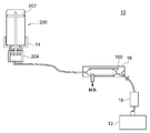
- FIG. 1 is a diagram illustrating an example of a configuration of a printing apparatus according to an embodiment of the present invention. It is a figure which shows an example of an ink container. It is a figure which shows the principle of a deaeration process. It is a figure explaining the characteristic of a gas-liquid separation means. It is a figure explaining the modification of a gas-liquid separation means. It is a figure explaining the structure of the printing apparatus of 2nd Embodiment. It is a figure explaining the structure of the printing apparatus of 3rd Embodiment. It is a figure explaining the structure of the printing apparatus of 4th Embodiment. It is a figure explaining the structure of the printing apparatus of 5th Embodiment. It is a figure explaining the structure of the printing apparatus concerning a modification. It is a figure explaining the structure of the printing apparatus concerning another modification.
- FIG. 1 shows an example of the configuration of a printing apparatus 10 according to an embodiment of the present invention.
- the printing apparatus 10 is an inkjet printer that performs printing by an inkjet method, and performs printing using the ink bottle 200 and the ink container 100.
- the ink bottle 200 is an ink storage unit that stores ink used for printing, and is installed in the printing apparatus 10 in a replaceable manner.
- the ink bottle 200 may store ink that has not been deaerated (non-deaerated ink).
- a known ink bottle can be suitably used.
- the ink bottle 200 supplies ink to the downstream side of the ink path by the water head value method using the ink head difference.
- the ink bottle 200 has a drop lid 202 that floats on the ink inside. If comprised in this way, the contact with the air of the ink in the ink bottle 200 can be decreased, and it can prevent appropriately a large amount of air melt
- the ink container 100 is an ink container (intermediate pack) that stores ink in the middle of the ink path in the printing apparatus 10.
- the ink container 100 for example, a container using a pack-like bag-like body can be suitably used.
- one end side (upstream side) of the ink container 100 is connected to the upstream container holding unit 14 and the ink bottle 200 via, for example, a tube. Accordingly, the ink container 100 receives the ink supplied from the ink bottle 200.
- the other end side (downstream side) of the ink container 100 is connected to the pressure regulator 18 and the inkjet head 12 via, for example, a tube.
- the ink container 100 supplies ink toward the inkjet head 12.
- the ink is deaerated in the ink container 100.
- the specific configuration of the ink container 100 will be described in more detail later.
- the printing apparatus 10 includes an inkjet head 12, an upstream container holding unit 14, an intermediate pack holding unit 16, and a pressure regulator 18.
- the inkjet head 12 is a print head that ejects ink droplets by an inkjet method.
- the inkjet head 12 has a plurality of nozzles that respectively eject ink droplets at a timing corresponding to an image to be printed.
- the inkjet head 12 for example, a known inkjet head can be suitably used.
- various known inks can be used.
- an ink an aqueous pigment ink, an aqueous dye ink, an aqueous latex ink, a UV (UltraViolet) curable ink, a solvent ink, or the like can be suitably used.
- the upstream container holding unit 14 is a holding unit that holds the ink bottle 200 in a replaceable manner on the upstream side of the ink flow path, and transfers the ink in the ink bottle 200 to the inkjet head 12 via the ink path. Supply towards. Further, in this example, the upstream container holding unit 14 includes an ink storage unit 204 that stores ink supplied from the ink bottle 200. With this configuration, ink can be more appropriately supplied from the ink bottle 200 to the inkjet head 12. The upstream container holding unit 14 has a drop lid in the ink storage unit 204. If comprised in this way, the contact with the air of the ink in the ink storage part 204 can be decreased, and it can prevent appropriately a large amount of air melt
- the intermediate pack holding part 16 is a part that holds the ink container 100, and holds the ink container 100 at a position between the upstream container holding part 14 and the inkjet head 12 in the ink path in the printing apparatus 10.
- the intermediate pack holding unit 16 is an example of an ink container holding unit.
- the intermediate pack holding unit 16 holds the ink container 100 at a position where it remains stationary even during the printing operation of the printing apparatus 10.
- the intermediate pack holder 16 preferably holds the ink container 100 at a position where it does not move with the inkjet head 12.
- the intermediate pack holding unit 16 holds the ink container 100 at a position where ink can be supplied to the inkjet head 12 by the water head value method. Thereby, the ink container 100 supplies ink to the inkjet head 12 by the water head value method.
- the water head value method is a method of supplying ink using gravity.
- the intermediate pack holding part 16 preferably has means for detecting the amount of ink in the ink container 100.
- the intermediate pack holding unit 16 preferably detects a decrease in the capacity of the ink container 100 or the end of ink.
- the amount of ink in the ink container 100 may be detected based on a change in the volume of the ink container that stores ink in the ink container 100.
- the ink is supplied to the ink container 100 while the ink is in the ink bottle 200. Therefore, by detecting a change in the volume of the ink container 100, it is possible to appropriately detect the timing at which the ink bottle 200 should be replaced or filled with ink.
- the pressure adjuster 18 is configured to adjust the pressure of ink supplied to the inkjet head 12, and is disposed between the ink container 100 and the inkjet head 12, whereby the pressure of ink supplied from the ink container 100 is set. Is adjusted and supplied to the inkjet head 12.
- the pressure adjuster 18 adjusts the pressure of the ink supplied to the nozzles of the inkjet head 12 to a pressure (negative pressure) in a predetermined range lower than the atmospheric pressure.
- the pressure adjuster 18 preferably adjusts the pressure at a position close to the inkjet head 12.
- the pressure regulator 18 is preferably held together with the inkjet head 12 by a member (for example, a carriage) that holds the inkjet head 12 in the printing apparatus 10.
- the pressure regulator 18 a known pressure regulator can be suitably used.
- various pressure dampers such as a mechanical pressure damper, a bag-type pressure damper, or a bellows-type damper can be used as the pressure regulator 18.
- the ink can be appropriately degassed by degassing the ink in the ink container 100.
- the printing apparatus 10 may have the same or similar configuration as a known inkjet printer.
- various known configurations necessary for the printing operation may be further included.
- the printing apparatus 10 may be a serial inkjet printer that causes the inkjet head 12 to perform a main scanning operation.
- the printing apparatus 10 may further include a main scanning drive unit that causes the inkjet head 12 to perform a main scanning operation of ejecting ink droplets while moving in a predetermined main scanning direction.
- the inkjet head 12 may further include a sub-scanning drive unit that moves the inkjet head 12 in the sub-scanning direction relative to the medium to be printed.
- the sub-scanning direction is, for example, a direction orthogonal to the main scanning direction.
- the inkjet head 12 may be a line head that performs printing without moving the main scanning operation or the like, for example.
- the printing apparatus 10 may perform printing using a plurality of colors of ink.
- the printing apparatus 10 may be provided for each color as necessary for the configuration of each unit.
- the printing apparatus 10 may perform printing using a plurality of ink bottles 200 and ink containers 100.
- the printing apparatus 10 may include a plurality of inkjet heads 12, an upstream container holding unit 14, an intermediate pack holding unit 16, and a pressure regulator 18 according to the number of colors used.
- the upstream container holding unit 14 is configured as a part of the printing apparatus 10.
- the upstream container holding unit 14 may be disposed in an ink supply device that can be separated from the main body portion of the printing apparatus 10, for example.
- the main body portion of the printing apparatus 10 is a portion including at least the inkjet head 12.
- the main body of the printing apparatus 10 may be a part that functions as an ink jet printer even when the ink supply device is separated.
- the intermediate pack holder 16 may hold an ink container (for example, an ink cartridge) that is not connected to the external ink bottle 200 or the like.
- an ink container having the same or similar configuration as the ink container 100 can be suitably used as the ink container except that it is not connected to the ink bottle 200.
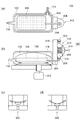
- FIG. 2A to 2D are views showing the ink container 100.
- FIG. 2A is a vertical sectional view showing the ink container 100
- FIG. 2B is a horizontal sectional view showing the ink container 100.
- FIG. 2C and FIG. 2D are diagrams illustrating the configuration of the valve 302 and the valve 306 in the ink container 100.
- the drawing is not a strict cross-sectional view or the like, but a drawing appropriately adjusted to make the configuration of the ink container 100 easy to understand.
- the ink container 100 includes an outer peripheral portion 102, an ink storage portion 104, a gas-liquid separation means 106, a decompression means 110, and a vibration stirring mechanism 112.
- the outer peripheral portion 102 is a casing portion of the ink container 100, and stores the ink storage portion 104, the gas-liquid separation means 106 (filter), and the like therein.
- the outer peripheral part 102 may be a fixed-shaped casing made of plastic or the like. More specifically, the outer peripheral portion 102 may be a housing portion of the cartridge-like ink container 100.
- the ink storage unit 104 is a part that stores ink in the ink container 100.
- the ink storage unit 104 is a bag-shaped pack member formed of a flexible film or the like, and stores ink in a state where it does not come into contact with air by changing the volume according to the amount of ink stored inside. To do.
- the term “not bringing the ink into contact with air” means that the ink is accommodated by design so that the ink is not intentionally brought into contact with the air.
- the ink containing portion 104 As a material for forming the ink containing portion 104, it is possible to use a flexible material whose volume changes according to a change in the internal volume of the ink and which does not dissolve or change in quality due to the ink.
- a flexible single layer or composite material, a film made of a plurality of materials, or the like can be suitably used.
- a plastic film such as polyester, polyethylene, nylon, or polypropylene can be suitably used.
- it is not restricted to a plastic film etc.
- the ink containing portion 104 does not necessarily have to be flexible as a whole, and at least a part of it may be flexible.
- the ink bottle 200 at a position higher than the ink container 100. If comprised in this way, supply of the ink from the ink bottle 200 to the ink container 100 can also be appropriately performed by the water head value method. Further, that the ink pressure in the ink container 104 in the ink container 100 and the atmospheric pressure are in balance is based on the difference in height between the ink level in the ink bottle 200 and the inkjet head 12. In the configuration in which ink is supplied by the water head value method, the pressure of the ink at the position of the ink container 100 may be an appropriate pressure.
- the ink is supplied from the ink bottle 200 to the ink container 100 using a pump or the like, and the liquid level of the ink in the ink container 100 and the height of the inkjet head 12. It is also conceivable to supply ink to the inkjet head 12 by the water head value method using the difference between the two. Even in such a configuration, by setting the ink pressure in the ink container 104 in the ink container 100 and the atmospheric pressure in a balanced state, the ink can be appropriately supplied by the water head value method.
- the gas-liquid separation means 106 is a gas-liquid separation means used for degassing ink in this example, and is disposed in the ink containing portion 104 in a state of being formed in a bag shape so as to surround a predetermined area. Established. In this case, the gas-liquid separation means 106 is formed in a bag shape, for example, when the region surrounded by the gas-liquid separation means 106 constitutes a space (air chamber 108) that can accommodate air. .
- the gas-liquid separation means 106 is a film-like gas-liquid separation means (for example, a filter) in which a large number of holes are formed. These holes in the gas-liquid separation means 106 are formed with a size that does not allow ink to pass and allows air to pass.
- the gas-liquid separating means 106 is placed in the ink containing section 104 so that the ink in the ink containing section 104 is in contact with the outer surface side and ink does not enter the area surrounded by the gas-liquid separating means 106. Arranged.
- the gas-liquid separation means 106 may be a mesh-like micro gas-liquid separation means.
- the gas-liquid separation means 106 can be formed of various materials that can form holes having a required hole diameter and that do not dissolve or change quality due to ink.
- the hole is formed by etching, it is conceivable to form the gas-liquid separation means 106 with various metals or the like subjected to SUS, nickel, chrome plating, or the like.
- a mesh-like gas-liquid separation means 106 formed of SUS, nickel or the like.
- the characteristics of the holes of the gas-liquid separation means 106 will be described in more detail later.
- the gas-liquid separation means 106 when the hole is formed by the laser beam, it is conceivable to form the gas-liquid separation means 106 with a metal or plastic film or the like.
- a plastic film for example, a film of polypropylene, parylene, fluororesin, nylon, polyethylene, polyester, or the like can be suitably used.
- the air chamber 108 is a space inside the gas-liquid separation means 106 formed in a bag shape.
- the air chamber 108 is surrounded by the gas-liquid separation means 106 in the ink containing portion 104, and becomes a space where only ink can enter without entering ink.
- the decompression unit 110 is a unit that decompresses the air chamber 108, and removes air in the ink in the ink storage unit 104 through the gas-liquid separation unit 106 by decompressing the air chamber 108. Accordingly, the decompression unit 110 functions as a decompression deaeration unit together with the gas-liquid separation unit 106 and degass the ink in the ink storage unit 104.
- the configuration and operation of the decompression unit 110 will be described in more detail later.
- the ink supply port 114 is a supply port for supplying ink to the ink storage unit 104.
- the ink supply port 114 is connected to the ink storage unit 204 (see FIG. 1) of the ink bottle 200 via the upstream container holding unit 14 (see FIG. 1). Accordingly, the ink supply port 114 receives ink supplied from the ink storage unit 204 of the ink bottle 200.
- the ink outlet 116 is a supply port that supplies ink toward the inkjet head 12.
- the ink outlet 116 is connected to the inkjet head 12 via the pressure regulator 18 (see FIG. 1).
- the vibration stirring mechanism 112 has a function of stirring the ink in the ink storage unit 104.
- the vibration stirring mechanism 112 stirs the ink in the vicinity of the gas-liquid separation unit 106 and the ink in a place away from the gas-liquid separation unit 106. As a result, deaeration of the entire ink in the ink container 104 is promoted.
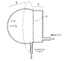
- FIG. 3 is a diagram showing the principle of the deaeration process.
- FIG. 3 is a view drawn for the purpose of illustrating the principle of the deaeration process, and the specific configuration is different from that of the ink container 100 shown in FIG.
- the gas-liquid separation membrane A has one surface in contact with the ink and the other surface in contact with the air.
- the constant pressure ink container portion B containing ink has a structure capable of keeping the pressure substantially constant. In the constant pressure ink container portion B, ink such as aqueous or solvent ink is placed.
- the deaeration process is performed by reducing the air in the decompression section C to about 4/5 of the atmospheric pressure with a decompression pump.
- the air in the decompression part C is decompressed, the gas dissolved or bubbled in the ink permeates from the gas-liquid separation membrane A into the decompression part C and is gasified.
- the ink since the ink has a liquid surface tension, the ink does not ooze out to the decompression portion through the fine holes of the gas-liquid separation membrane A. By this principle, ink can be deaerated.
- the pore size of the gas-liquid separation membrane that allows gas to permeate and does not allow liquid to pass through is theoretically determined. For example, when the shape of the hole is a circle, a liquid having a surface tension of 30 mN / m theoretically does not ooze out from a hole having a hole diameter of 1.2 ⁇ m or less under 1 atm.
- the average pore diameter is 5 ⁇ m or less, preferably 1 ⁇ m or less, more preferably 0.2 ⁇ m or less to 0.005 ⁇ m or more. The principle of the deaeration process has been described above.
- the printing operation is performed with the upstream container holding portion 14 open.
- the printing operation may be performed in a state where the ink supply port 114 is closed by plugging or the like.
- the decompression means 110 is a means for decompressing the inside of the gas-liquid separation means 106 (portion of the air chamber 108). By depressurizing the portion of the air chamber 108, the air in the ink in the ink storage unit 104 is removed via the gas-liquid separation unit 106.
- the decompression unit 110 is a unit that mechanically decompresses using the urging force of the urging unit, and includes a valve 302, a connection portion 304, a valve 306, a flexible member 308, an air chamber 310, a spring 312, and a pressure plate. 314.
- cost can be held down by making the decompression means 110 mechanical.
- the valve 302 is a valve that connects the air chamber 310 in the decompression means 110 and the outside of the decompression means 110. Further, in this example, as can be understood from the configuration shown in FIG. 2C, the valve 302 is closed when the pressure in the air chamber 310 is lower than the atmospheric pressure, and the air chamber 310 is in the atmospheric pressure. It opens and closes so as to open at the time of pressurization when the pressure is higher than that. Thereby, the valve 302 is opened when the air in the air chamber 310 is discharged to the outside.
- connection portion 304 is an air flow path that connects the air chamber 108 surrounded by the gas-liquid separation means 106 and the air chamber 310 of the decompression means 110.
- the connection unit 304 connects the air chamber 108 and the air chamber 310 via the valve 306.
- the valve 306 is a valve that connects the air chamber 108 and the air chamber 310 via the connection portion 304.
- the valve 306 opens at the time of decompression in which the pressure in the air chamber 310 is lower than that in the air chamber 108, and the air chamber 310 is in the air chamber. It opens and closes so that it closes at the time of pressurization in which the pressure is higher than that in the inside 108. Accordingly, the valve 306 is opened when the air in the air chamber 108 flows to the air chamber 310.
- the flexible member 308 is a member constituting at least a part of the wall surface of the air chamber 310, and moves at least a part of the inner wall of the air chamber 310 by covering at least a part of the space functioning as the air chamber 310. Alternatively, it is configured to be deformable. As the flexible member 308, for example, a non-breathable film or the like can be suitably used.
- the air chamber 310 is a closed space connected to the outside only through the valve 302 and the valve 306.
- a spring 312 and a pressure plate 314 are accommodated in the air chamber 310.
- One end of the spring 312 is fixed to the base 316 of the decompression means 110 and the other end is configured to press the flexible member 308 via the pressure plate 314.
- the spring 312 functions as a return spring that returns the flexible member 308 to its original state when the flexible member 308 is deformed in a predetermined direction.
- the pressure plate 314 is a member that receives the other end of the spring 312, and is disposed between the other end of the spring 312 and the flexible member 308, thereby applying the biasing force of the spring 312 to the flexible member 308. To communicate.
- the pressure reducing means 110 when the pressure is reduced by the pressure reducing means 110, first, the volume of the air chamber 310 is reduced by pressing the pressure plate 314 via the flexible member 308 by a manual operation of the user. The flexible member 308 is deformed.
- the valve 302 is opened. In addition, thereby, the air in the air chamber 310 is discharged so that the pressure in the air chamber 310 is balanced with the atmospheric pressure. In this case, since the valve 306 is closed, air does not flow into the air chamber 108 surrounded by the gas-liquid separation means 106.
- the flexible member 308 swells via the pressure plate 314 due to the returning operation of the spring 312 which was contracted at the time of pressing,
- the volume of the air chamber 310 is expanded. Due to this increase in volume, the pressure in the air chamber 310 changes to a negative pressure lower than the atmospheric pressure. The negative pressure is maintained before the spring 312 is fully extended.
- the spring 312 biases the flexible member 308 constituting at least a part of the inner wall of the air chamber 310 in the direction of expanding the volume of the air chamber 310. Accordingly, the spring 312 or the like operates as a negative pressure maintaining mechanism that maintains the negative pressure of the air chamber 310. In this case, the negative pressure generated by the spring 312 or the like can be adjusted to a desired pressure by the spring force of the spring 312 or the like.
- valve 302 is closed when the negative pressure in the air chamber 310 is maintained by the spring 312 or the like. Further, if air exists in the air chamber 108 surrounded by the gas-liquid separation means 106 and the pressure in the air chamber 108 is higher than that of the air chamber 310, the valve 306 is opened. Therefore, in this case, the air in the air chamber 108 is discharged to the air chamber 310 via the connection portion 304 and the valve 306. As a result, the pressure in the air chamber 108 is also adjusted to a negative pressure.
- the pressure of the ink stored in the ink storage unit 104 is in balance with the atmospheric pressure. Therefore, when the decompression by the decompression unit 110 is performed, a pressure difference occurs between the ink side and the air chamber 108 side in the gas-liquid separation unit 106. In this case, the air in the ink can be moved to the air chamber 108 to degas the ink. As described above, by depressurizing the air chamber 108 surrounded by the gas-liquid separation unit 106 by the decompression unit 110, the ink in the ink storage unit 104 can be appropriately deaerated.
- the ink can be appropriately deaerated without using a pressure reducing electric pump or the like by mechanically reducing the pressure with a configuration using the spring 312 or the like. Therefore, according to this example, it is possible to appropriately prevent the cost of the printing apparatus 10 from being increased by the deaeration device.
- the spring 312 is deformed so that the air in the air chamber 310 is exhausted, and then the spring 312 is flexed in the direction in which the air chamber 310 expands.
- the air chamber 310 can be maintained in a decompressed state. Thereby, in the ink container 100, ink can be deaerated more appropriately over time.
- the ink storage portion 104 that has a volume that changes according to the amount of ink. It can be said that. More specifically, for example, when a fixed configuration is used instead of a deformable configuration for the ink storage portion 104, if the air chamber 108 surrounded by the gas-liquid separation means is decompressed, the inside of the ink storage portion 104 The ink pressure is also reduced. As a result, there is a possibility that the supply of ink by the water head method may be hindered.
- the ink can be degassed by the ink container 100, for example, it is not necessary to degas the ink before shipping the ink. Therefore, the cost of ink shipped from the factory can be reduced appropriately. In addition, even when the printing apparatus 10 has not been used for a long time, the ink can be appropriately degassed before use. Furthermore, since it becomes possible to sufficiently deaerate immediately before use, the ink deaeration level is appropriate for the tubes and joints constituting the ink flow path without using expensive materials. Can be kept in.
- the pressure of the ink in the ink containing portion 104 is balanced with the atmospheric pressure, it is not necessary to use an intermediate tank or the like that is open to the atmosphere when supplying the ink by the head value method. As a result, even when printing is not performed for a long time, it is possible to appropriately suppress a decrease in the ink deaeration level.
- the cost of the apparatus can be appropriately suppressed in this respect.
- the cause of malfunction can be reduced in the operation of supplying ink. Further, the ink can be appropriately deaerated without deaeration at a position close to the inkjet head 12. Therefore, the configuration around the inkjet head 12 does not increase in size.
- the ink stored in the ink storage unit 104 can be degassed by the gas-liquid separation means 106.
- the gas-liquid separation means 106 can appropriately prevent the flow path resistance from increasing.
- the influence of the channel resistance can be greatly reduced compared to the case where deaeration is performed using a hollow fiber filter. Therefore, according to this example, it is possible to appropriately supply ink without using a strong pressurized liquid feeding pump or the like. Thereby, the cost of the apparatus can be reduced more appropriately.
- the stored ink is further deaerated to ensure a sufficient time for the ink to contact the gas-liquid separation means 106. This makes it possible to degas the ink more appropriately over time.
- the gas-liquid separation means 106 of this example degasses the ink by allowing only air in the ink to pass through instead of passing the ink as described above. Therefore, it is possible to realize a configuration in which the gas-liquid separation means is less likely to be clogged as compared with a hollow fiber filter or the like. In addition, it becomes easy to regenerate the gas-liquid separation means 106 by washing.
- the ink is degassed with a light work load. be able to.
- the negative pressure can be maintained by the elasticity of the flexible member 308 and the mechanical configuration using the spring 312 or the like, it is possible to prevent the ink deaeration level from being lowered for a long time. Therefore, according to this example, it is possible to appropriately perform long-term stable ink ejection by the inkjet head 12 without burdening the user with work.
- the volume of the air chamber 310 can be appropriately confirmed. Further, based on the change in volume of the air chamber 310, the reduced pressure state in the air chamber 310 can be appropriately confirmed.
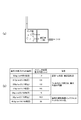
- FIG. 4 is a diagram for explaining the characteristics of the gas-liquid separation means 106.
- FIG. 4A is a diagram showing a simplified operation principle of the gas-liquid separation means 106 in this example.
- FIG. 4B is a table showing an example of the relationship between the magnitude of the differential pressure generated between both surfaces of the gas-liquid separation means 106 and the required maximum hole diameter of the mesh.
- the gas-liquid separation means 106 is formed so as to surround the air chamber 108, so that only one surface side is in contact with the ink. Therefore, when the state of the gas-liquid separation means 106 is schematically shown, as shown in FIG. 4A, the ink chamber and the decompression chamber (air chamber 108) are divided by the mesh-like gas-liquid separation means 106. It can be said that the decompression chamber is decompressed by the decompression means 110.
- whether or not the ink passes through the hole of the gas-liquid separation unit 106 depends on the size of the hole of the gas-liquid separation unit 106, the surface tension of the ink, and the pressure difference between both surfaces of the gas-liquid separation unit 106. It depends on (differential pressure).
- the surface tension of the ink is considered to be constant, a hole for allowing only air to pass without passing ink according to the differential pressure between both surfaces of the gas-liquid separating means 106 generated by reducing the pressure of the air chamber 108 is provided.
- the maximum diameter (the required maximum hole diameter of the mesh) will be determined.
- the surface tension of the ink is St
- the differential pressure between both surfaces of the gas-liquid separation unit 106 is Ms
- the maximum diameter at which the ink meniscus is not destroyed in the hole of the gas-liquid separation unit 106 is 2r (radius is r )
- the diameter 2r of the hole where the meniscus is not broken is about 1.2 ⁇ m.
- the ink meniscus generated in the hole of the gas-liquid separation means 106 is broken even when the air chamber 108 is decompressed to the maximum and the differential pressure Ms becomes 1 atm. There will be no. As a result, even in this state, it can be said that the ink can be deaerated without passing the ink through the gas-liquid separation means 106.
- the differential pressure Ms is made smaller than 1 atm.
- the smaller the hole of the gas-liquid separation means 106 the more difficult it is to process, and this causes a cost increase of the gas-liquid separation means 106. Therefore, regarding the size of the hole formed in the gas-liquid separation unit 106, the size of the differential pressure Ms generated between both surfaces of the gas-liquid separation unit 106, the ease of processing the hole of the gas-liquid separation unit 106, and the like are taken into consideration. Is preferably set.
- FIG. 4B is a table showing an example of the relationship between the magnitude of the differential pressure generated between both surfaces of the gas-liquid separation means 106 and the required maximum hole diameter of the mesh. This relationship is a relationship when the surface tension of the ink is 30 mN / m. As can be seen from this table, the required maximum hole diameter of the mesh increases as the differential pressure generated between both surfaces of the gas-liquid separation means 106 decreases. As a result, the processing of the gas-liquid separation means 106 becomes easier.
- the hole of the gas-liquid separation means 106 is smaller than, for example, the nozzle of the inkjet head.
- values such as 19.2 ⁇ m and 30 ⁇ m are the same as the nozzle diameter of a normal high-resolution inkjet head. Therefore, it is considered that when the hole of the gas-liquid separating means 106 is enlarged to such a degree, it becomes easier to pass ink for the ink jet printer. Therefore, it is considered preferable to make the holes of the gas-liquid separation means 106 equal to or less than these values.
- the hole of the gas-liquid separation means 106 is not necessarily strictly smaller than the nozzle. It is also possible to make it slightly larger than the nozzle. Therefore, when considered more generally, it is considered preferable to set the diameter of the hole of the gas-liquid separation means 106 to about 20 ⁇ m or less.
- the diameter of the hole is preferably 15 ⁇ m or less. That is, in the case shown in the table, it can be said that the range of the maximum hole diameter that can be suitably used as the gas-liquid separation means when the required maximum hole diameter of the mesh is 15 ⁇ m or less. If comprised in this way, deaeration of ink can be performed more appropriately by using the mesh-like gas-liquid separation means 106 and utilizing the surface tension of the ink.
- the diameter of the hole of the gas-liquid separation means 106 may be, for example, the diameter when the opening area of the hole is converted into a circle.
- the maximum diameter of the holes may be, for example, the maximum diameter in the range of the diameter variation of the plurality of holes formed in the gas-liquid separation unit.
- the maximum diameter of the hole may be the maximum diameter after removing some abnormal holes within a range in which, for example, the influence of unintended ink leakage does not occur.
- the maximum diameter of the hole is preferably 10 ⁇ m or less, more preferably 5 ⁇ m or less.
- the minimum diameter of the holes is preferably 0.2 ⁇ m or more. That is, the maximum diameter of the hole is preferably in the range of 0.2 to 20 ⁇ m, for example. Further, considering the ease of processing, it is preferable that the maximum diameter of the hole is, for example, about 12 ⁇ m or more.
- the decompression unit 110 is disposed at a position adjacent to the ink storage unit 104 while being always connected to the air chamber 108 surrounded by the gas-liquid separation unit 106.
- the decompression means 110 may be installed with a configuration different from that shown in FIG.
- the decompression unit 110 may be installed in a removable state at a position adjacent to the ink storage unit 104.
- the decompression unit 110 may be disposed so as to be accommodated in the outer peripheral portion 102. If comprised in this way, the structure by which all the structures for pressure reduction and deaeration were enclosed in the ink container 100 is realizable.
- the decompression unit 110 may be configured as a separate part attached to the ink container 100 instead of being included in the ink container 100. In these cases, the ink can be appropriately degassed as described above.
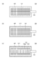
- FIG. 5A is a diagram for explaining a modification of the gas-liquid separation means 106.
- the gas-liquid separation means 106 according to the modification is formed by forming a water-repellent polyethylene single layer membrane 107 (gas-liquid separation membrane) into a bag shape.
- the polyethylene single layer membrane 107 has micropores having an average pore diameter of several nm to 0.1 ⁇ m. The micropores have a size that allows gas to pass but does not allow ink to pass.
- the gas-liquid separation means 106 is configured by the polyethylene single-layer membrane 107 is described, but it can also be configured by using a polyethylene membrane formed by a plurality of layers.
- a porous filter 109 having an average pore diameter of 100 ⁇ m or more is filled in a bag-like polyethylene single layer membrane 107.
- the pore diameter of the porous filter 109 is large enough to allow not only gas but also liquid to pass through.
- the reason why the porous filter 109 having such a pore diameter is provided inside the polyethylene single layer membrane 107 is to increase the mechanical strength of the gas-liquid separation means 106.
- the gas-liquid separation means 106 is manufactured by bonding a polyethylene single layer membrane 107 and a porous filter 109 together.
- the gas-liquid separating means 106 does not allow ink to enter the porous filter 109 portion because the bag-like polyethylene single-layer membrane 107 allows gas to pass therethrough but does not allow ink in the ink containing portion 104 to pass through. That is, gas exists in the porous filter 109 portion.
- the portion of the porous filter 109 corresponds to the decompression section C.
- the ink oozes into the gas-liquid separation means 106 because the polyethylene single-layer membrane 107 has water repellency. Risk can be reduced.
- FIG. 5B is a diagram illustrating a configuration of the gas-liquid separation unit 106 according to the second modification.
- a porous filter 109 having an average pore diameter of 100 ⁇ m or more is filled in a bag-like polyethylene single layer membrane 107.
- the non-porous film 1071 covers the outside of the polyethylene single layer membrane 107.
- the film thickness of the non-porous film 1071 is sufficiently thin to allow gas to pass through.
- the gas-liquid separation unit 106 according to Modification 1 includes the non-porous film 1071, and thus can further reduce the risk of ink oozing into the gas-liquid separation unit 106.
- FIG. 5C is a diagram illustrating a configuration of the gas-liquid separation unit 106 according to the third modification.
- the gas-liquid separation means 106 according to the modified example 3 includes a porous gas-liquid separation means 109a having an average pore diameter of 100 ⁇ m or more and a coarse pore gas-liquid having an average pore diameter of several hundreds ⁇ m or more in a bag-like polyethylene single layer membrane 107. Two kinds of porous filters 109 of the separating means 109b are filled. Further, the non-porous film 1071 covers the outside of the polyethylene single layer membrane 107. The film thickness of the non-porous film 1071 is sufficiently thin to allow gas to pass through.
- the gas-liquid separation means 106 according to the modified example 3 can further reduce the risk of ink oozing into the gas-liquid separation means 106 by providing the non-porous film 1071, and the coarse pore gas-liquid separation means 109b having a large pore diameter. By having it, the mechanical strength can be further increased.
- the polyethylene single-layer membrane 107 is used as the gas-liquid separation membrane, but the gas-liquid separation means 106 according to Modification 4 of the first embodiment is made of a fluororesin. Since the fluororesin has high water repellency, the possibility of ink entering the gas-liquid separation unit 106 can be reduced.
- Modification 5 of the first embodiment In the above-described modification, the polyethylene single-layer membrane 107 is used as the gas-liquid separation membrane, but the gas-liquid separation means 106 according to Modification 5 of the first embodiment is configured by a mesh subjected to super-water-repellent treatment. To do. With this configuration, the possibility of ink entering the gas-liquid separation unit 106 can be reduced, and a mesh can be configured using various materials.
- the decompression unit 110 is configured to be detachable from the ink containing portion 104. May be. Further, the decompression unit 110 may be a separate part attached to the ink container 100. As described above, by adopting a configuration in which the decompression unit 110 is removable from the ink storage unit 104, the ink storage unit 104 that stores the gas-liquid separation unit 106 can be replaced.
- a new ink container 100 (equipped with the ink storage unit 104) is attached to the decompression unit 110, thereby reducing the decompression unit 110.
- the ink container 100 can be used at a low cost.
- the gas-liquid separation unit 106 may be configured to be able to be taken out from or inserted into the ink storage unit 104. That is, the printing apparatus according to the modified example 7 of the present embodiment includes a bag-like gas-liquid separation unit configured by the inkjet head 12, the intermediate pack holding unit 16 that holds the ink container 100, and the polyethylene single layer membrane 107. 106 and a decompression unit 110 connected to the space inside the gas-liquid separation unit 106. The gas-liquid separation unit 106 is placed in the ink container 100 held by the intermediate pack holding unit 16 to perform deaeration. Do.
- the ink degassing process can be performed by inserting the gas-liquid separation means 106 into the ink container 104.
- the polyethylene single layer membrane 107 which is a gas-liquid separation membrane is formed in a bag shape and the gas-liquid separation means 106 is described as an example. It need not be a separation membrane.
- the gas-liquid separation means may be a gas-liquid separation film in which at least a part of the outer periphery has water repellency. If at least part of the gas-liquid separation film has water repellency, the gas in the ink can be taken into the gas-liquid separation means from that part.
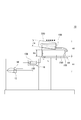
- FIG. 6 is a diagram illustrating a configuration of the ink container 100 according to the second embodiment.
- FIG. 6A is a vertical sectional view showing the configuration of the ink container 100 in the second embodiment
- FIG. 6B is a horizontal sectional view showing the configuration of the ink container 100 in the second embodiment.
- the basic configuration of the ink container 100 of the second embodiment is the same as that of the first embodiment, but the configuration of the decompression means 110 is different.
- the ink container 100 is means for reducing pressure by a configuration like a syringe, and includes a valve 302, a connection portion 304, a valve 306, an air chamber 310, a spring 312, a cylinder portion 320, a piston 322, And a stopper 324.
- valve 302, the connection portion 304, the valve 306, and the air chamber 310 correspond to the same numbered configurations of the respective components in FIG.
- the cylinder part 320 and the piston 322 are structures corresponding to the cylinder part and the piston in the syringe, and when the piston 322 is inserted into the cylinder part 320, as shown in FIG.
- An air chamber 310 is formed inside 320.
- the spring 312 biases the piston 322 in the direction in which the air chamber 310 expands.
- the stopper 324 is a stopper member for preventing the piston 322 from excessively moving, and stops the cylindrical portion 320 that moves in the upward direction in the drawing by the biasing force of the spring 312 at a preset position.
- the piston 322 when the ink is deaerated, for example, the piston 322 is pushed downward in FIG. 6A by the user's manual operation, and the air in the air chamber 310 is discharged from the valve 302 to the outside. Discharge. Thereafter, when the user releases his / her hand, the piston 322 moves upward in the drawing in accordance with the biasing force of the spring 312. In this case, the volume of the air chamber 310 is expanded, and the air chamber 310 has a negative pressure. As a result, the inside of the air chamber 108 surrounded by the gas-liquid separation means 106 is also decompressed via the connection portion 304 and the valve 306.
- the gas-liquid separation means 106 (for example, a filter) can appropriately degas the ink.
- the negative pressure in the air chamber 310 is maintained at least until the spring 312 is fully extended. Therefore, also in this modification, a negative pressure can be appropriately maintained for a long time by a mechanical configuration. This also makes it possible to degas the ink appropriately and sufficiently.
- the specific configuration of the decompression unit 110 is not limited to the above, and other configurations may be used.
- the pressure is not limited to a configuration in which the pressure is reduced by a user's manual operation, but may be reduced by an electric configuration or the like.
- the ink can be appropriately degassed by the gas-liquid separation means 106 inside the ink containing portion 104. Further, since the polyethylene single layer membrane 107 has water repellency, it is possible to reduce a risk that the ink penetrates into the gas-liquid separation means 106.
- the negative pressure in the air chamber 310 is maintained at least until the spring 312 is fully extended. Therefore, the negative pressure can be appropriately maintained for a long time by the mechanical configuration, and the ink can be appropriately deaerated. This also makes it possible to degas the ink appropriately and sufficiently.
- FIG. 7 is a diagram illustrating a configuration of the printing apparatus 10 according to the third embodiment.
- the basic configuration of the printing apparatus 10 according to the third embodiment is the same as that of the first embodiment, but the printing apparatus 10 according to the third embodiment is arranged in the ink bottle 200 shown in FIG. Instead, a replacement ink pack 220 is provided. Further, the upstream container holding unit 14 holds the replacement ink pack 220 with a configuration corresponding to the ink bottle 200. In the present embodiment, the upstream container holding part 14 is also an example of the ink container holding part.
- the printing apparatus 10 has a replacement ink pack 220 instead of the ink bottle 200 shown in FIG. Further, the upstream container holding unit 14 holds the replacement ink pack 220 with a configuration corresponding to the ink bottle 200.
- the upstream container holding unit 14 in the present embodiment is also an example of the ink container holding unit.
- the replacement ink pack 220 is, for example, a replacement large-capacity ink pack, and stores a larger volume of ink than the ink container 100.
- the replacement ink pack 220 further degass the ink inside the ink container 100 in the same manner as the ink container 100 described with reference to FIG.
- the replacement ink pack 220 has an outer peripheral portion 102, an ink storage portion 104, a gas-liquid separation means 106, a decompression means 110, an ink outlet 116, and the like, and will be described with reference to FIGS.
- Ink is deaerated in the same manner as the ink container 100 that has been used. Thereby, for example, ink can be deaerated in a container that stores a large volume of ink. In this case, the deaeration level of the ink can be increased by deaerating the ink in both the replacement ink pack 220 in the uppermost stream of the ink path and the ink container 100 in the middle.
- the ink container 100 at the intermediate position may not be degassed, but the ink may be degassed only by the replacement ink pack 220.
- the replacement ink pack 220 may be supplemented with ink.
- the replacement ink pack 220 is temporarily removed from the upstream container holding portion 14 and the ink is replenished from the plug portion connected to the upstream container holding portion 14. Thereby, a large volume of ink can be appropriately supplied.
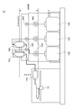
- FIG. 8 is a diagram illustrating a configuration of the printing apparatus 10 according to the fourth embodiment.
- the basic configuration of the printing apparatus 10 of the fourth embodiment is the same as that of the first embodiment, but the printing apparatus 10 of the fourth embodiment is arranged in the ink bottle 200 shown in FIG. Instead, the replacement ink pack 220 and the non-replacement ink pack 230 are held.
- the upstream container holding unit 14 holds the replacement ink pack 220 and the non-exchange ink pack 230. Also in this modified example, the upstream container holding part 14 is an example of an ink container holding part.
- the replacement ink pack 220 and the non-replacement ink pack 230 are used for the number of ink colors.
- the replacement ink pack 220 and the non-replacement ink pack 230 for each color are held side by side in the horizontal direction by the upstream container holding unit 14.
- the replacement ink pack 220 is a replacement ink container. Further, in this modification, the replacement ink pack 220 is a pack-like container whose volume changes according to the amount of ink inside, and is not replaced while being disposed at a position higher than the non-replacement ink pack 230. By being connected to the ink pack 230, ink is supplied to the non-exchangeable ink pack 230 by the water head value method.
- the non-replacement ink pack 230 is a permanent ink container that is not replaced, and supplies ink to the ink container 100 while storing ink received from the replacement ink pack 220 inside.
- the non-replaceable ink pack 230 is also a pack-like container whose volume changes in accordance with the amount of ink inside, and is disposed at a position higher than the ink container 100, so that it can be transferred to the ink container 100 by the head value method.
- Supply ink Also in this example, the ink container 100 is disposed at a position higher than the inkjet head 12 and supplies ink received from the non-exchange ink pack 230 to the inkjet head 12 by the water head value method.
- ink can be appropriately supplied to the inkjet head 12 by the water head value method. Further, by storing ink using the replacement ink pack 220 and the non-replacement ink pack 230 on the upstream side of the ink container 100 in the ink path, it is possible to store a large amount of ink more appropriately.
- the replacement ink pack 220 and the non-replacement ink pack 230 are connected in series, when the ink in the replacement ink pack 220 becomes empty, the non-replacement ink pack 230
- the replacement ink pack 220 can be replaced while supplying ink to the ink container 100. Therefore, with this configuration, it is possible to cause the printing apparatus 10 to perform a continuous operation for a long time more appropriately while appropriately replacing the replacement ink pack 220.
- this modification it is preferable to provide a detector that detects the start of ink decrease, the end of ink (ink end), and the like at the positions of the non-replaceable ink pack 230 and the ink container 100. If comprised in this way, the residual amount of ink etc. in each position can be detected appropriately. Thereby, it is possible to appropriately detect the timing at which the replacement ink pack 220 should be replaced. In this case, it is particularly preferable to provide a detector that detects a decrease in ink in the non-replaceable ink pack 230. With this configuration, it is possible to appropriately detect the ink end of the upstream replacement ink pack 220.
- the water head difference is the distance H1 + H2 shown in the figure.
- the minimum water head difference is H1 shown in the drawing. Therefore, in this modification, the water head difference of ink changes in the range of H1 to H1 + H2.
- the replacement ink pack 220 and the non-replacement ink pack 230 are preferably installed sideways so that the longitudinal direction is parallel or nearly parallel to the horizontal direction, as shown in the figure.
- the height H2 which is the change range of the water head difference
- the change range of the ink head difference can be appropriately suppressed by comparing the case where the longitudinal direction of the replacement ink pack 220 and the non-exchange ink pack 230 is directed in the vertical direction.
- the replacement ink pack 220 is preferably not tilted to the side, but tilted to some extent as shown in the figure. With this configuration, the ink in the replacement ink pack 220 can be supplied to the non-replacement ink pack 230 more appropriately.
- the capacity of the non-exchange ink pack 230 is larger than that of the replacement ink pack 220. More specifically, as shown in the drawing, when the longitudinal direction of the replacement ink pack 220 is L, the length of the non-exchange ink pack 230 in the longitudinal direction is preferably larger than L. With this configuration, the non-replaceable ink pack 230 that increases in weight due to a large capacity (for example, an ultra-large capacity) does not move, and only the lighter replacement ink pack 220 is replaced.
- the replacement ink pack 230 can be appropriately filled with ink. This also makes it possible for a weak worker or the like to easily replace the ink.
- the capacity of the non-replaceable ink pack 230 may be an integral multiple of the capacity of the replacement ink pack 220. If comprised in this way, a large capacity
- the capacity of the replacement ink pack 220 may be 2L, and the capacity of the non-replacement ink pack 230 may be 3L, 6L.
- the replacement ink pack 220 is sequentially replaced and attached three times, so that the downstream non-exchange ink pack 230 can be filled. After that, by mounting the fourth replacement ink pack 220, the replacement ink pack 220 and the non-replacement ink pack 230 can be combined to store 8 L of large-capacity ink.
- the replacement ink pack 220, the non-exchange ink pack 230, and the ink container 100 may be configured to be deaerated by the gas-liquid separation unit 106.
- the configuration capable of degassing by the gas-liquid separation means 106 is a configuration capable of degassing in the same or similar manner as the ink container 100 described with reference to FIGS. If constituted in this way, deaeration of ink can be performed appropriately, for example.
- the replacement ink pack 220, and the non-replacement ink pack 230 may be configured to be able to deaerate. .
- the gas-liquid separating means 106 can be used for a long time without being disposable. Therefore, with this configuration, the operation cost of the printing apparatus 10 can be more appropriately reduced.
- FIG. 9A is a diagram illustrating a configuration of the ink container 100 according to the fifth embodiment.
- the ink storage unit 104 includes a housing having two side surfaces 104b and 104c facing the bottom surface 104a, and a flexible film 104d that covers the top surface.
- the upper film 104d is lowered with a decrease in ink.
- An ink remaining amount detection unit 118 is provided on the film 104d. When the height of the ink remaining amount detection unit 118 becomes lower than a predetermined height, it is detected that the remaining amount of ink has decreased.
- the heights of the two side surfaces 104b and 104c of the ink containing portion 104 are different.
- a magnetic stirrer 120 that stirs the liquid using magnetic force is provided on the higher side surface 104c.
- the magnetic stirrer 120 includes a stirring blade 120a that stirs ink in the ink storage unit 104, and a drive unit 120b that rotates the stirring blade 120a with a magnetic force.
- the ink container 100 of the fifth embodiment has a connection portion 304 that connects the gas-liquid separation means 106 to a decompression means (not shown).
- the gas-liquid separation means 106 performs an ink deaeration process as in the above-described embodiment.
- FIG. 9B is a diagram showing a configuration of an ink container 100 according to a modification of the fifth embodiment.
- the basic configuration of the ink container 100 according to the modified example is the same as that of the above-described embodiment, except that the magnetic stirrer 120 is provided on the bottom surface 104 a of the ink containing unit 104.
- FIG. 10 is a diagram illustrating the configuration of the printing apparatus 10 according to the modification.
- a plurality of ink containers 130 are placed below.
- An external intermediate pack 132 and a main body intermediate pack 134 are disposed on the path between the ink container 130 and the inkjet head 12 in the printing apparatus 10.
- the main body intermediate pack 134 is disposed at a position higher than the inkjet head 12, and the external intermediate pack 132 is disposed at a position higher than the main body intermediate pack 134.
- ink flows from the external intermediate pack 132 to the main body intermediate pack 134 and from the main body intermediate pack 134 to the inkjet head 12 by the water head value method using the ink head difference.
- ink is pumped from the underlying ink container 130 to the external intermediate pack 132 using the ink pumping pump 136 with the valve 138 opened.
- the valve 138 is closed except when ink is pumped up.
- the deaeration mechanism is provided at one or a plurality of locations of the main body intermediate pack 134, the external intermediate pack 132, and the ink container 130.
- the configuration of the deaeration mechanism can be the same as that of the above-described embodiment.
- FIG. 11 is a diagram illustrating the configuration of the printing apparatus 10 according to another modification.
- a plurality of ink containers 140 are placed below, and this configuration is a bulk ink supply system that enables continuous printing for a long time.
- a bulk tank 142 and a cartridge 144 are provided on the path between the ink container 140 and the inkjet head 12 in the printing apparatus 10.
- the cartridge 144 is arranged at a position higher than the inkjet head 12, and the bulk tank 142 is arranged at a position higher than the cartridge 144.
- ink flows from the bulk tank 142 to the cartridge 144 and from the cartridge 144 to the inkjet head 12 by the water head value method using the water head difference of the ink.
- Ink is pumped from the ink container 140 placed below to the bulk tank 142 using the ink pumping pump 146 with the valve 148 opened.
- the valve 148 is closed except when ink is pumped up.
- a deaeration mechanism is provided in one or both of the cartridge 144 and the bulk tank 142.
- the configuration of the deaeration mechanism can be the same as that of the above-described embodiment.
- the decompression means 110 may be accommodated in the outer peripheral portion 102. With this configuration, it is possible to realize a configuration in which all the configurations for decompression and deaeration are enclosed in the ink container 100.
- the decompression means 110 is configured to perform decompression by manual operation.
- a configuration of automatic decompression by electric motor or the like may be employed.
- the pressure may be reduced using an intermittent drive pump or the like.
- the ink container 100 of Modifications 1 to 3 of the first embodiment is a gas-liquid separation in which a polyethylene single layer membrane 107 having water repellency is formed in a bag shape and a porous filter 109 is filled therein. Means 106 are provided. By depressurizing the inside of the gas-liquid separation unit 106 by the decompression unit 110, the gas in the ink can be degassed via the gas-liquid separation film 107. Since the gas-liquid separation film 107 has water repellency, the possibility of ink passing through the gas-liquid separation film 107 can be reduced.
- the gas-liquid separation means 106 of the ink container 100 according to the first to third modifications of the first embodiment includes a polyethylene single layer membrane 107 as a gas-liquid separation film.
- the inventor's experiment confirmed that the gas-liquid separation means 106 using the polyethylene single layer membrane 107 can appropriately perform the deaeration process of the ink.
- the gas-liquid separation film is made of a fluororesin. Since the fluororesin has high water repellency, it is preferable as a gas-liquid separation membrane of the gas-liquid separation means 106.
- the gas-liquid separation means 106 of the ink container 100 according to Modification 5 of the first embodiment is constituted by a mesh in which the gas-liquid separation film is subjected to super-water-repellent treatment.
- various materials can be used as the gas-liquid separation membrane.
- the gas-liquid separation means 106 is filled with a porous filter 109 having a pore diameter larger than that of the polyethylene single layer membrane 107. Strength can be increased.
- the polyethylene single layer membrane 107 is covered with a non-porous film 1071 having a film thickness that allows gas to pass therethrough.
- the ink container 100 of the present embodiment since the ink storage unit 104 has flexibility, the ink pressure inside the ink storage unit 104 and the atmospheric pressure are balanced, and in the printing apparatus 10, the water head value is determined. Ink supply according to the method can be appropriately performed.
- the ink container 100 includes the decompression unit 110 connected to the connection unit 304.
- the ink container 100 provided with the decompression unit 110 can be used as an ink container for storing ink on the path of the printing apparatus, for example.
- the ink container 100 according to the first embodiment includes the vibration stirring mechanism 112 that stirs ink, and includes the magnetic stirrer 120 that stirs ink according to the fifth embodiment. With this configuration, it is possible to effectively perform deaeration by stirring the ink in the ink storage unit 104.
- the printing apparatus 10 includes an ink jet head 12 that ejects ink droplets by an ink jet method, and an ink container 100 that stores ink to be supplied to the ink jet head 12.
- a connection unit 304 that connects the space inside the liquid separation unit 106 and the decompression unit 110 outside the ink storage unit 104 is provided.
- the gas in the ink can be degassed through the polyethylene single layer membrane 107 by reducing the pressure inside the gas-liquid separating means 106 by the pressure reducing means 110. Further, since the polyethylene single layer membrane 107 has water repellency, the possibility of ink passing through the polyethylene single layer membrane 107 can be reduced. Further, since the gas-liquid separation means 106 can degas, for example, even when printing is performed using ink that has not been degassed, the deaeration level of the ink can be appropriately increased before being supplied to the inkjet head 12. it can.
- the printing apparatus includes an inkjet head 12, an intermediate pack holding unit 16 that holds an ink container 100 disposed in the middle of an ink supply path, and a polyethylene single layer membrane 107.
- the air-liquid separation means 106 and the decompression means 110 connected to the space inside the gas-liquid separation means 106, and the gas-liquid in the ink container 100 held by the intermediate pack holding part 16. Separation means 106 is inserted to perform deaeration.
- the present invention can be suitably used for an ink container, for example.
Landscapes
- Ink Jet (AREA)
Abstract
【課題】インクジェットヘッド用のインクについて、より適切な方法で脱気を行う。 【解決手段】インクジェットヘッド12へ供給するインクを貯留するインク容器100であって、インク収容部104と、インクを通過させず、かつ、空気を通過させる大きさの穴が複数形成された気液分離手段106と、インク収容部104内のインクをインクジェットヘッド12へ向けて流すインク出口116とを備え、気液分離手段106は、空気室108の周囲を囲むように、袋状に形成されており、空気室108内にインクを入れず、かつ、外面側がインクと接する状態で、インク収容部104内に配設され、空気室108の気圧が大気圧より低い圧力にされることにより、気液分離手段106は、インク収容部104内のインクを脱気する。
Description
本発明は、インク容器、印刷装置、及びインク供給方法に関する。
従来、インクジェット方式で印刷を行うインクジェットプリンタが広く用いられている。また、インクジェットプリンタで用いるインク(インクジェットインク)について、インク中に気体が一定量以上溶解している場合や、気体が気泡として存在している場合には、インクジェットヘッドからのインク滴の吐出が不安定になることが知られている。そのため、従来、インクジェットプリンタでは、脱気されたインクをインクジェットヘッドに供給することが一般的である。
インクを脱気する方法として、インクの製造工場において、あらかじめ溶存気体量が一定量以下になるように脱気する方法がある。また、ユーザが準備した非脱気インクを脱気する方法としては、インクジェットプリンタのインクの流路中において、中空糸フィルタや気液分離フィルタを使って脱気を行う方法が知られている(特許文献1)。
インクを脱気する方法として、例えば、工場で予め脱気を行う方法が考えられる。この場合、インクを製造する工場において、インク中の溶存気体量が一定量以下になるように脱気を行う。また、その後、気体の透過し難い袋(インクパック等)に、脱気されたインクを充填(パッキング)する。
このようにして脱気を行った場合、インクの品質管理を容易に行うことができる。また、インクの使用時において、インクジェットプリンタの内部でもインクが空気にさらされない構造を用いることにより、インクの品質を安定させやすくなる。また、このようにすると、インクの供給経路の途中で脱気を行う必要がないため、インクを供給するためのポンプ等を用いないより簡単な構成でインクを供給することができる。具体的には、インクの水頭差を利用して自動的にインクを供給する水頭値方式でインクジェットヘッドへインクを供給することにより、低コストの構成をより適切に実現することができる。
しかし、工場でインクの脱気を行う場合、脱気のための工程を行うことや、そのための設備を設けることが必要になるため、インクの製造コストが上昇することになる。また、製造後、インクを使用するまでの期間が長期になった場合、インクの脱気レベルが低下するおそれもある。その結果、インクジェットヘッドから吐出されるインク滴の吐出が不安定になるおそれもある。更に、工場で脱気がされたインクを用いる場合、インクジェットプリンタにおけるインクの流路(供給路)でインクが滞留した場合にも脱気レベルの低下が生じないように、インクの流路を構成するチューブ(インク供給チューブ)やジョイント等について、気体の透過率の小さな材料で形成された部材を用いることが必要になる場合もある。その結果、インクジェットプリンタの装置コストの上昇要因にもなる。
また、インクを脱気する方法としては、例えば、インクジェットプリンタでのインクの流路中で脱気を行うことも考えられる。この場合、インクの流路の途中において、インクジェットプリンタに内蔵又は外付けにより、中空糸フィルタを使った中空糸脱気装置等を設けることが考えられる。
このように構成した場合、脱気がされていないインクや、空気にさらされた状態でインクを貯留するインク容器を用いることが可能になるため、インクボトル等のような大容量インク容器を使うことができる。これにより、インクの製造コストを低減することが容易になる。
しかし、インクの流路中で脱気を行う場合、通常、脱気のための減圧を行うために真空ポンプ等が必要になり、装置のコストが上昇することになる。また、例えば中空糸脱気装置等を用いる場合、中空糸フィルタの流体抵抗が大きいため、インク供給用の強い加圧送液ポンプ等も必要になる。その結果、装置のコストが大きく上昇する要因になる。
また、インクの流路中で脱気を行う場合、通常、インクの流路の途中に中間タンク等を設けることが必要になる。この場合、中間タンクとは、インクの流路の途中においてインクを貯留するインク貯留部のことである。また、この場合、中間タンクにおけるインクのレベルを検出し、例えば、加圧送液ポンプのオン状態とオフ状態とを切り替えて、インクの供給量の調節制御を行うこと等も必要になる。そのため、この点でも、装置のコストが上昇する要因になる。また、インクを供給する動作において、誤動作の要因も増えることになる。
更に、インクの供給圧力を調整するため、中間タンクは、一部が空気解放された状態でインクを貯留する。そのため、中間タンクにインクが貯留された状態で長時間放置された場合等に、インクの脱気レベルが低下し、インクジェットヘッドからのインク滴の吐出が不安定になる場合もある。
また、インクの流路中で脱気を行う具体的な構成としては、特許文献1に開示されているように、インクジェットヘッドの圧力室に隣接する位置において、中空糸フィルタと真空ポンプとを用いて脱気を行う構成等も考えられる。このように構成すれば、インクジェットヘッドの近傍で脱気を行うことができる。
しかし、このような構成を用いた場合、真空配管や脱気のための機構をインクジェットヘッド毎に設置することが必要になる。そのため、インクジェットヘッドの周囲の構成が大型化するという問題が生じることになる。特に、インクジェットヘッドが移動するシリアルプリンタにおいては、インクジェットヘッドの周囲の大型化は、好ましくない。更に、この場合、インクの脱気を行う脱気時間は、インクが流路を通過する短い時間に限られるため、長時間の連続印刷を行う場合等には、脱気不足が生じ、インクジェットヘッドからのインク滴の吐出が不安定になりやすい。
そのため、従来、より適切な方法でインクを脱気する構成が望まれていた。そこで、本発明は、上記の課題を解決できるインク容器、印刷装置、及びインク供給方法を提供することを目的とする。
本願の発明者は、インクジェットプリンタ用のインクを脱気する方法について、鋭意研究を行った。そして、先ず、工場で予め脱気する方法や、インクの流路中に脱気のための機構(脱気モジュール等)を設置する方法ではなく、インクパック等のインク容器内に貯留されているインクに対して脱気を行うことを考えた。また、本願の発明者は、更なる鋭意研究により、インク容器内のインクを脱気する構成として、インクを通過させず、かつ、空気を通過させる大きさの穴が複数形成された気液分離手段を用いることを考えた。また、インク容器においてインクを収容するインク収容部について、内部に収容するインクの量に応じて容積が変化する構成を用いることを考えた。
このように構成すれば、インク容器自体に脱気機能を持たせることができる。そのため、脱気されていない非脱気インクをインク容器に充填した場合にも一定時間後には、インクジェットヘッドへ脱気されたインクを供給することができる。これにより、従来の方法により工場で脱気を行う場合に得られる特長を維持しながら、その問題点を適切に解消することができる。更には、インクの流路中に中空糸脱気装置等を設ける従来の方法において問題となっていたインクの製造コスト上昇の原因等も解消し、低い製造コストでより適切にインクを供給することができる。すなわち、上記の課題を解決するために、本発明は、以下の構成を有する。
(構成1)インクジェット方式でインク滴を吐出するインクジェットヘッドへ供給するインクを貯留するインク容器であって、インク容器においてインクを収容するインク収容部と、インクを通過させず、かつ、空気を通過させる大きさの穴が複数形成された気液分離手段と、インク収容部内のインクをインクジェットヘッドへ向けて流すインク出口と、を備え、気液分離手段は、袋状に形成されており、気液分離手段に囲まれた領域内にインクを入れず、かつ、外面側がインクと接する状態で、インク収容部内に配設され、気液分離手段に囲まれた領域の気圧が大気圧より低い圧力にされることにより、気液分離手段は、インク収容部内のインクを脱気する。
気液分離手段について、袋状に形成されているとは、例えば、予め設定された領域の周囲を囲むように、袋状に形成されていることである。この場合、気液分離手段に囲まれた領域とは、この予め設定された領域であってよい。
このように構成した場合、インク容器内のインクを脱気することができるため、インクの出荷前にインクを脱気する必要はない。そのため、工場から出荷されるインクの製造コストを適切に低減できる。また、インクジェットプリンタを長期間使用しなかった場合等にも、使用前に適切にインクを脱気することができる。更には、使用の直前等に十分に脱気を行うことが可能になるため、インクの流路を構成するチューブやジョイント等について、高価な材料を用いなくても、インクの脱気レベルを適切に保つことができる。
また、このように構成した場合、インクが、当該インクの流路に沿って気液分離手段(フィルタ)を通過する構成ではないため、気液分離手段により流路抵抗が大きくなることを適切に防ぐことができる。特に、中空糸フィルタを用いて脱気を行う場合等と比べ、流路抵抗の影響を大幅に低減できる。そのため、強い加圧送液ポンプ等を用いなくても、インクを適切に供給することができる。これにより、装置のコストを適切に低減できる。
また、インク容器は、内部に収容するインクの量に応じて容積が変化する容器であることが好ましい。このように構成した場合、インク収容部内のインクの圧力と大気圧とが釣り合った状態を適切に維持できる。そのため、水頭値方式によりインクを供給する構成を適切に用いることができる。これにより、装置のコストを適切に低減できる。
更に、インク収容部内のインクの圧力と大気圧とが釣り合った状態であるため、水頭値方式でインクを供給する場合において、例えば、大気開放された中間タンク等を用いなくても、インクジェットヘッドへのインクの供給を適切に行うことができる。その結果、長時間印刷を行わない場合等にも、インクの脱気レベルの低下を適切に抑えることができる。また、中間タンクにおけるインクのレベルを検出してインクの供給量の調節制御等を行うことも不要になるため、この点でも、装置のコストを適切に抑えることができる。また、インクを供給する動作において、誤動作の要因を減らすこともできる。
また、このように構成した場合、インクジェットヘッドと近接した位置で脱気を行わなくても、インクの脱気を適切に行うことができる。そのため、インクジェットヘッドの周囲の構成が大型化することもない。
以上のように、インクジェットプリンタを使用する現場においてユーザ自身で実施できる脱気機能を持つインク供給システムを適切に実現することができる。そのため、例えば、インクボトルによりインクを供給する場合や、非脱気インクを収容するインクパックを用いる場合にも、インクジェットヘッドへインクを供給する前にインクの脱気レベルを適切に高めることができる。また、これにより、インクジェットヘッドにおけるインクの吐出安定性を適切に向上させることができる。従って、脱気されたインクをインクジェットヘッドへより適切に供給できる。
尚、この構成において、気液分離手段により囲まれた領域は、例えば、手動又は電動等で減圧を行う減圧手段により、減圧される。この場合、減圧手段は、インク容器に含まれる構成であってよい。例えば、減圧手段は、インク容器を構成する袋の中に配設されてよい。このように構成すれば、インク容器に含まれる構成のみを用いて、インクの脱気をより適切に行うことができる。また、減圧手段は、インク容器とは別に用意されてもよい。この場合、インクジェットプリンタへのインク容器の取り付け時等に、減圧手段とインク容器とを接続してもよい。また、インク容器内にインクが完全に充填された状態で、かつインク容器内の圧力を一定に保つことができれば、必ずしもインク容器の容積を変化させなくてもよい。そのため、このような場合、容積が一定のインク容器を用いることも考えられる。このように構成した場合も、インクの脱気を適切に行うことができる。
(構成2)気液分離手段に形成された複数の穴において、最大の直径は20μm以下である。このように構成すれば、気液分離手段において、インクを通過させず、かつ、空気を通過させる構成をより適切に実現できる。
尚、気液分離手段における穴の直径とは、例えば、穴の開口面積を円形に換算した場合の直径であってよい。また、穴の最大の直径(最大穴径)は、好ましくは10μm以下、更に好ましくは5μm以下である。また、気液分離手段において、穴の最少(最少穴径)の直径は、0.2μm以上であることが好ましい。すなわち、穴の直径は、例えば0.2~20μmの範囲であることが好ましい。
また、穴の最大の直径とは、例えば、気液分離手段に形成された複数の穴の直径のバラツキの範囲において最大となる直径のことであってよい。また、穴の最大の直径とは、意図しないインクの漏れ等の影響が生じない範囲で、一部の異常な穴を除いた中での最大の直径であってよい。
(構成3)気液分離手段に囲まれた領域を減圧する減圧手段を更に備える。このように構成すれば、気液分離手段に囲まれた領域を適切に減圧することができる。また、これにより、インクの脱気をより適切に行うことができる。
尚、減圧手段は、気液分離手段に囲まれた領域と接続された状態で、インク収容部と隣接した位置に配設される。この場合、減圧手段は、気液分離手段に囲まれた領域と常に接続されている状態で配設されてよい。また、減圧手段は、インク収容部に対し、取り外し可能な状態で設置されてもよい。
(構成4)減圧手段は、付勢手段の付勢力を用いて機械的に減圧を行う手段である。このように構成すれば、機械的に減圧を行うことにより、減圧用の電動ポンプ等を用いることなく、インクの脱気を適切に行うことができる。これにより、インクジェットプリンタにおける装置のコストをより適切に低減できる。
(構成5)減圧手段は、気液分離手段に囲まれた領域と繋がる空間であり、当該空間を構成する内壁の少なくとも一部が移動又は変形可能である空気室と、空気室内の空気を外部へ排出する場合に開くバルブと、空気室の体積を広げる方向へ内壁の少なくとも一部を付勢する付勢手段とを有する。このように構成すれば、機械的な方法による減圧をより適切に行うことができる。
尚、付勢手段としては、バネ等を好適に用いることができる。また、空気室内の空気を排出した状態になるようにバネ等の付勢手段を変形させ、その後、バネ等が元に戻るまでの間付勢力を維持させること等が考えられる。このように構成すれば、空気室が減圧された状態を適切に維持することができる。これにより、時間をかけてインクをより適切に脱気することができる。
(構成6)気液分離手段は、インク収容部内に貯留されているインクを脱気する。このように構成すれば、時間をかけてインクをより適切に脱気することができる。
尚、従来の構成において、中空糸フィルタ等を用いて脱気を行う場合、通常、インクの流路に沿って流れているインクに対し、脱気を行うことになる。そして、この場合、中空糸フィルタ等をインクが通過する短時間のみしか、インクを脱気できないことになる。
これに対し、構成6のように構成した場合、流路を流れているインクではなく、貯留されているインクに対して脱気を行うことにより、インクが気液分離手段に接している時間を十分に確保することができる。これにより、上記のように、時間をかけてインクをより適切に脱気することが可能になる。
(構成7)インク収容部へインクを供給するインク供給口を更に備える。このように構成すれば、必要に応じてインク容器にインクを充填することができる。
尚、インク供給口については、インクの充填時以外は閉じた状態にして、インクを充填する場合にのみ開くことが考えられる。また、インク容器については、インクの流路の途中に設置する中間パックとして用いること等も考えられる。この場合、このインク容器は、インクの流路の更に上流側に設置される別のインク容器から、インク供給口を介して、インクの供給を受ける。このような場合には、インク供給口を開いた状態のまま、印刷の動作を行うことも考えられる。
(構成8)インクジェット方式で印刷を行う印刷装置であって、インクジェット方式でインク滴を吐出するインクジェットヘッドと、インクジェットヘッドへ供給するインクを貯留するインク容器を保持するインク容器保持部と、を備え、インク容器は、インク容器においてインクを収容するインク収容部と、インクを通過させず、かつ、空気を通過させる大きさの穴が複数形成された気液分離手段と、インク収容部内のインクをインクジェットヘッドへ向けて流すインク出口とを有し、気液分離手段は、袋状に形成されており、気液分離手段に囲まれた領域内にインクを入れず、かつ、外面側がインクと接する状態で、インク収容部内に配設され、気液分離手段に囲まれた領域の気圧が大気圧より低い圧力にされることにより、気液分離手段は、インク収容部内のインクを脱気する。このように構成すれば、構成1と同様の効果を得ることができる。
(構成9)インクジェット方式でインク滴を吐出するインクジェットヘッドへインクを供給するインク供給方法であって、インクを貯留するインク容器からインクジェットヘッドへインクを供給し、インク容器は、インク容器においてインクを収容するインク収容部と、インクを通過させず、かつ、空気を通過させる大きさの穴が複数形成された気液分離手段と、インク収容部内のインクをインクジェットヘッドへ向けて流すインク出口と、を備え、気液分離手段は、袋状に形成されており、気液分離手段に囲まれた領域内にインクを入れず、かつ、外面側がインクと接する状態で、インク収容部内に配設され、気液分離手段に囲まれた領域の気圧が大気圧より低い圧力にされることにより、気液分離手段は、インク収容部内のインクを脱気する。このように構成すれば、構成1と同様の効果を得ることができる。
(構成10)本発明のインク容器は、インクを収容するインク収容部と、前記インク収容部内に設けられた気液分離手段であって、少なくとも一部が撥水性を有する気液分離膜によって構成された袋状の気液分離膜と、前記気液分離手段の内部の空間と前記インク収容部の外部の減圧手段とを接続する接続部とを備える。
この構成により、接続部に減圧手段を接続し、減圧手段によって気液分離手段の内部の空間を減圧することで、気液分離膜を介してインク中の気体を脱気することができる。ここで、気液分離膜は、気体は通過させるがインクは通過させない大きさの多数の孔を有する膜である。本発明は、気液分離膜が撥水性を有することにより、インクが気液分離膜を通過してしまう可能性を低減することができる。
(構成11)本発明のインク容器において、前記気液分離膜は、ポリエチレン単層メンブレンによって構成されていてもよいし、フッ素樹脂によって構成されていてもよい。また、前記気液分離膜は、超撥水処理したメッシュによって構成されていてもよい。
(構成12)本発明のインク容器において、前記気液分離手段の内部には、前記気液分離膜よりも孔径が大きい多孔フィルムが充填されていてもよい。これにより、気液分離膜の機械的な強度を高めることができる。
(構成13)本発明のインク容器は、前記気液分離膜が、気体を通す程度の膜厚の無孔フィルムによって覆われていてもよい。無孔フィルムは十分に薄ければ、気体を通すことができる。気液分離膜を無孔フィルムで覆うことによって、気液分離手段の内部にインクが滲み込むリスクをいっそう低減できる。
(構成14)本発明のインク容器において、前記インク収容部は、可撓性を有する構成でもよい。この構成により、インク収容部内のインクの圧力と大気圧とが釣り合うので、印刷装置において、水頭値方式によるインクの供給を適切に行うことができる。
(構成15)本発明のインク容器は、前記接続部に接続された減圧手段を備えてもよい。このように減圧手段を備えたインク容器は、印刷装置の経路において、インクを貯留するインク容器として用いることができる。
(構成16)本発明のインク容器は、前記インク収容部内のインクを攪拌する攪拌手段を備えてもよい。この構成により、気液分離手段の近くにあるインクと気液分離手段から離れた場所にあるインクを攪拌することで、効果的に脱気を行うことができる。
(構成17)本発明の印刷装置は、インクジェット方式で印刷を行う印刷装置であって、インクジェット方式でインク滴を吐出するインクジェットヘッドと、前記インクジェットヘッドへ供給するインクを貯留するインク容器とを備え、前記インク容器は、インクを収容するインク収容部と、前記インク収容部内に設けられた気液分離手段であって、少なくとも一部が撥水性を有する気液分離膜によって構成された袋状の気液分離手段と、前記気液分離手段の内部の空間と前記インク収容部の外部の減圧手段とを接続する接続部とを備える。
この構成により、接続部に減圧手段を接続し、減圧手段によって気液分離手段の内部を減圧することで、気液分離膜を介してインク中の気体を脱気することができる。また、気液分離膜が撥水性を有することにより、気液分離膜をインクが通過してしまう可能性を低減することができる。
(構成18)本発明の印刷装置は、インクジェット方式で印刷を行う印刷装置であって、インクジェット方式でインク滴を吐出するインクジェットヘッドと、前記インクジェットヘッドへ供給するインクを貯留するインク容器を保持するインク容器保持部と、少なくとも一部が撥水性を有する気液分離膜によって構成された袋状の気液分離手段と、前記気液分離手段の内部の空間に接続された減圧手段とを備え、前記インク容器保持部に保持されたインク容器の中に前記気液分離手段を入れて、脱気を行う。
この構成により、減圧手段によって気液分離手段の内部を減圧することで、気液分離膜を介してインク中の気体を脱気することができる。また、気液分離膜が撥水性を有することにより、気液分離膜をインクが通過してしまう可能性を低減することができる。また、インク容器保持部に保持されたインク容器に気液分離手段を入れることで脱気を行えるので、インク容器を入れ替えても脱気を行える。
本発明によれば、例えば、インクジェットヘッド用のインクについて、より適切な方法で脱気することができる。
[印刷装置の構成]
以下、本発明に係る実施形態を、図面を参照しながら説明する。図1は、本発明の一実施形態に係る印刷装置10の構成の一例を示す。本例において、印刷装置10は、インクジェット方式で印刷を行うインクジェットプリンタであり、インクボトル200及びインク容器100を用いて印刷を行う。
以下、本発明に係る実施形態を、図面を参照しながら説明する。図1は、本発明の一実施形態に係る印刷装置10の構成の一例を示す。本例において、印刷装置10は、インクジェット方式で印刷を行うインクジェットプリンタであり、インクボトル200及びインク容器100を用いて印刷を行う。
インクボトル200は、印刷に使用するインクを貯留するインク貯留部であり、印刷装置10に交換可能に設置される。インクボトル200は、脱気がされていないインク(非脱気インク)を貯留してよい。インクボトル200としては、公知のインクボトルを好適に用いることができる。また、本例において、インクボトル200は、インクの水頭差を利用する水頭値方式により、インクの経路の下流側へインクを供給する。また、インクボトル200は、内部のインクに浮かぶ落とし蓋202を有する。このように構成すれば、インクボトル200内のインクの空気への接触を少なくし、貯留中のインクに多量の空気が溶け込むことを適切に防ぐことができる。
また、インク容器100は、印刷装置10におけるインクの経路の途中においてインクを貯留するインク容器(中間パック)である。インク容器100としては、例えばパック状の袋状体を用いた容器等を好適に用いることができる。また、本例のインクの経路において、インク容器100の一端側(上流側)は、例えばチューブ等を介して、上流容器保持部14及びインクボトル200と接続される。また、これにより、インク容器100は、インクボトル200から供給されるインクを受け取る。また、インク容器100の他端側(下流側)は、例えばチューブ等を介して、圧力調整器18及びインクジェットヘッド12と接続される。これにより、インク容器100は、インクジェットヘッド12へ向けてインクを供給する。また、本例においては、インク容器100において、インクの脱気を行う。インク容器100の具体的な構成については、後に更に詳しく説明をする。
印刷装置10は、インクジェットヘッド12、上流容器保持部14、中間パック保持部16、及び圧力調整器18を備える。インクジェットヘッド12は、インクジェット方式でインク滴を吐出する印刷ヘッドである。本例において、インクジェットヘッド12は、印刷する画像に応じたタイミングでインク滴をそれぞれ吐出する複数のノズルを有する。
インクジェットヘッド12としては、例えば公知のインクジェットヘッドを好適に用いることができる。また、インクジェットヘッド12においては、各種の公知のインクを用いることができる。このようなインクとして、水性顔料インク、水性染料インク、水性ラテックスインク、UV(UltraViolet)硬化インク、ソルベントインク等を好適に用いることができる。
上流容器保持部14は、インクの流路の上流側でインクボトル200を交換可能な態様で保持する保持部であり、インクボトル200内のインクを、インクの経路を介して、インクジェットヘッド12へ向けて供給する。また、本例において、上流容器保持部14は、インクボトル200から供給されるインクを貯留するインク貯留部204を有している。このように構成すれば、インクボトル200からのインクジェットヘッド12へのインクの供給をより適切に行うことができる。また、上流容器保持部14は、インク貯留部204において、落とし蓋を有する。このように構成すれば、インク貯留部204内のインクの空気への接触を少なくし、貯留中のインクに多量の空気が溶け込むことを適切に防ぐことができる。
中間パック保持部16は、インク容器100を保持する部分であり、印刷装置10におけるインクの経路において、上流容器保持部14とインクジェットヘッド12との間の位置で、インク容器100を保持する。また、中間パック保持部16は、インク容器保持部の一例である。中間パック保持部16は、印刷装置10の印刷動作中も静止している位置において、インク容器100を保持する。中間パック保持部16は、インクジェットヘッド12と共に移動をしない位置でインク容器100を保持することが好ましい。
中間パック保持部16は、水頭値方式でインクジェットヘッド12へインクを供給できる位置において、インク容器100を保持する。これにより、インク容器100は、水頭値方式により、インクジェットヘッド12へインクを供給する。
尚、水頭値方式とは、重力を利用してインクを供給する方式である。中間パック保持部16は、インク容器100内のインクの量を検知する手段を有することが好ましい。例えば、中間パック保持部16は、インク容器100の容量減少や、インクの終了を検知することが好ましい。この場合、インク容器100においてインクを収容するインク収容部の体積変化に基づき、インク容器100内のインクの量を検知してよい。このように構成すれば、インクボトル200にインクが入っている間はインク容器100にインクが供給される。したがって、インク容器100の容積変化を検知することで、インクボトル200の交換またはインクの充填等を行うべきタイミングを適切に検知することができる。また、インク容器100からインクジェットヘッド12へインクを供給しつつインクボトル200の交換等を行うことが可能であるため、印刷動作の途中においても、印刷の動作を止めることなく、インクボトル200の交換等を適切に行うことができる。そのため、長時間連続してインクを供給可能な構成を適切に実現できる。
圧力調整器18は、インクジェットヘッド12へ供給するインクの圧力を調整する構成であり、インク容器100とインクジェットヘッド12との間に配設されることにより、インク容器100から供給されるインクの圧力を調整して、インクジェットヘッド12へ供給する。また、圧力調整器18は、インクジェットヘッド12のノズルへ供給されるインクの圧力について、大気圧よりも低い所定の範囲の圧力(負圧)に調整する。圧力調整器18は、インクジェットヘッド12に近い位置で圧力の調整を行うことが好ましい。例えば、圧力調整器18は、印刷装置10においてインクジェットヘッド12を保持する部材(例えばキャリッジ等)によりインクジェットヘッド12と共に保持されることが好ましい。
また、圧力調整器18としては、公知の圧力調整器を好適に用いることができる。例えば、圧力調整器18として、機械式の圧力ダンパ、袋方式の圧力ダンパ、又は蛇腹方式のダンパ等の各種の圧力ダンパを用いることができる。
以上の構成により、インクジェットヘッドによる印刷を適切に行うことができる。また、この場合、インク容器100においてインクを脱気することにより、インクの脱気を適切に行うことができる。
尚、図1においては、説明の便宜上、印刷装置10について、要部に着目して簡略化した構成のみを示している。しかし、上記及び以下に説明をする点を除き、印刷装置10は、公知のインクジェットプリンタと同一又は同様の構成を有してよい。また、上記に示した構成以外に、印刷動作に必要な公知の各種構成を更に有してよい。例えば、印刷装置10は、インクジェットヘッド12に主走査動作を行わせるシリアル方式のインクジェットプリンタであってよい。この場合、印刷装置10は、所定の主走査方向へ移動しつつインク滴を吐出する主走査動作をインクジェットヘッド12に行わせる主走査駆動部等を更に有してよい。また、印刷対象の媒体(メディア)に対して相対的に副走査方向へインクジェットヘッド12を移動させる副走査駆動部等を更に有してよい。この場合、副走査方向とは、例えば、主走査方向と直交する方向である。また、インクジェットヘッド12は、例えば、主走査動作等の移動をすることなく印刷を行うラインヘッドであってもよい。
また、印刷装置10は、複数色のインクを用いて印刷を行ってもよい。この場合、印刷装置10は、各部の構成について、必要に応じて、各色毎に備えてよい。印刷装置10は、複数のインクボトル200及びインク容器100を用いて印刷を行ってよい。また、印刷装置10は、使用する色数に応じて、それぞれ複数のインクジェットヘッド12、上流容器保持部14、中間パック保持部16、及び圧力調整器18を備えてよい。
また、図1に示した構成において、上流容器保持部14は、印刷装置10の一部として構成されている。しかし、上流容器保持部14は、例えば、印刷装置10における本体部分から分離可能なインク供給装置に配設されてもよい。この場合、印刷装置10の本体部とは、少なくともインクジェットヘッド12を備える部分である。また、この場合、印刷装置10の本体部は、インク供給装置が分離された単独の状態でもインクジェットプリンタとして機能する部分であってよい。また、印刷装置10の本体部が単独の状態で印刷を行う場合、中間パック保持部16において、外部のインクボトル200等には接続されないインク容器(例えば、インクカートリッジ等)を保持してよい。この場合、インク容器として、インクボトル200に接続しない以外の点ではインク容器100と同一又は同様の構成を有するインク容器等を好適に用いることができる。
[インク容器の構成]
続いて、インク容器100の構成について、更に詳しく説明をする。
図2(a)~図2(d)は、インク容器100を示す図である。図2(a)は、インク容器100を示す垂直断面図、図2(b)は、インク容器100を示す水平断面図である。図2(c)及び図2(d)は、インク容器100におけるバルブ302及びバルブ306の構成を示す図である。
尚、図2においては、図示の便宜上、厳密な断面図等ではなく、インク容器100の構成をわかりやすくするように適宜調整を行った図面を示している。
続いて、インク容器100の構成について、更に詳しく説明をする。
図2(a)~図2(d)は、インク容器100を示す図である。図2(a)は、インク容器100を示す垂直断面図、図2(b)は、インク容器100を示す水平断面図である。図2(c)及び図2(d)は、インク容器100におけるバルブ302及びバルブ306の構成を示す図である。
尚、図2においては、図示の便宜上、厳密な断面図等ではなく、インク容器100の構成をわかりやすくするように適宜調整を行った図面を示している。
本例において、インク容器100は、外周部102、インク収容部104、気液分離手段106、減圧手段110、及び、振動攪拌機構112を有する。外周部102は、インク容器100の筐体部分であり、内部にインク収容部104及び気液分離手段106(フィルタ)等を収容する。外周部102は、プラスチック等で形成された固定形状の筐体であってよい。より具体的に、外周部102は、カートリッジ状のインク容器100の筐体部分であってよい。
インク収容部104は、インク容器100においてインクを収容する部分である。インク収容部104は、可撓性のフィルム等で形成された袋状のパック部材であり、内部に収容するインクの量に応じて容積を変化させることにより、空気に接触させない状態でインクを収容する。この場合、インクを空気に接触させないとは、設計上、意図的にインクを空気に接触させることがないようにして、インクを収容することである。
なお、インク収容部104を形成する材料としては、インクの内容量変化に応じて体積が変わる可撓性の材料で、かつ、インクにより溶解や変質の起こらない各種の材料を用いることができる。例えば、可撓性の単層又は複合材料や、複数の材料からなるフィルム等を好適に用いることができる。このようなフィルムとして、例えば、ポリエステル、ポリエチレン、ナイロン、ポリプロピレン等のプラスチックフィルム等を好適に用いることができる。また、プラスチックフィルム等に限らず、例えば、気体透過率を低減できる金属や無機酸化物等の層を含む構成を用いてもよい。また、インク収容部104については、必ずしも全体が可撓性を有する必要はなく、少なくともその一部が可撓性を有していればよい。
このように構成すれば、インク収容部104内のインクの圧力と大気圧とが釣り合った状態を適切に維持できる。これにより、印刷装置10(図1参照)において、水頭値方式によるインクの供給を適切に行うことができる。
尚、図1に示した構成の印刷装置10においては、インクボトル200をインク容器100よりも高い位置へ設置することが考えられる。このように構成すれば、インクボトル200からインク容器100へのインクの供給についても、水頭値方式で適切に行うことができる。また、インク容器100におけるインク収容部104内のインクの圧力と大気圧とが釣り合った状態であるとは、インクボトル200におけるインクの液面とインクジェットヘッド12との高さの差を利用して水頭値方式でインクを供給する構成において、インク容器100の位置でのインクの圧力が適正な圧力になっていることであってよい。また、印刷装置10の構成の変形例においては、インクボトル200からインク容器100へのインクの供給についてはポンプ等を用いて行い、インク容器100におけるインクの液面とインクジェットヘッド12との高さの差を利用して水頭値方式でインクジェットヘッド12へインクを供給すること等も考えられる。このように構成した場合も、インク容器100におけるインク収容部104内のインクの圧力と大気圧とを釣り合った状態にすることにより、水頭値方式で適切にインクを供給できる。
気液分離手段106は、本例においてインクの脱気に用いる気液分離手段であり、予め設定された領域の周囲を囲むように袋状に形成された状態で、インク収容部104内に配設される。この場合、気液分離手段106が袋状に形成されるとは、例えば、気液分離手段106に囲まれた領域が空気を収容し得る空間(空気室108)を構成する状態のことである。気液分離手段106は、多数の穴が形成された膜状の気液分離手段(例えば、フィルタ)である。そして、気液分離手段106におけるこれらの穴は、インクを通過させず、かつ、空気を通過させる大きさで形成されている。これにより、気液分離手段106は、インク収容部104内のインクと外面側が接し、かつ、気液分離手段106により囲まれた領域にはインクが入らないようにして、インク収容部104内に配設される。
より具体的に、気液分離手段106は、メッシュ状のマイクロ気液分離手段であってよい。また、気液分離手段106としては、必要な穴径の穴が形成可能であり、かつ、インクにより溶解や変質の起こらない各種の材料で形成することができる。例えば、穴の形成をエッチングにより行う場合には、SUS、ニッケル、又はクロムメッキ等を施した各種金属等で気液分離手段106を形成することが考えられる。また、金属メッシュ状にする場合や、細線を編むことで網目を形成する場合には、SUSやニッケル等で形成された網状の気液分離手段106を用いることが考えられる。また、気液分離手段106の穴の特徴については、後に更に詳しく説明をする。
ここで、レーザ光線により穴を形成する場合には、金属やプラスチックのフィルム等で気液分離手段106を形成することが考えられる。この場合、プラスチックのフィルムとしては、例えば、ポリプロピレン、パリレン、フッ素樹脂、ナイロン、ポリエチレン、又はポリエステル等のフィルムを好適に用いることができる。
空気室108は、袋状に形成された気液分離手段106の内部の空間である。空気室108は、インク収容部104内で気液分離手段106に囲まれることにより、インクが入らず、かつ、空気のみが入り得る空間になる。減圧手段110は、空気室108を減圧する手段であり、空気室108を減圧することにより、気液分離手段106を介して、インク収容部104内のインク中の空気を取り除く。また、これにより、減圧手段110は、気液分離手段106と共に減圧脱気手段として機能し、インク収容部104内のインクを脱気する。減圧手段110の構成及び動作については、後に更に詳しく説明をする。
インク供給口114は、インク収容部104へインクを供給するための供給口である。本例において、インク供給口114は、上流容器保持部14(図1参照)を介して、インクボトル200のインク貯留部204(図1参照)と接続される。また、これにより、インク供給口114は、インクボトル200のインク貯留部204から供給されるインク受け取る。
インク出口116は、インクジェットヘッド12へ向けてインクを供給する供給口である。インク出口116は、圧力調整器18(図1参照)を介して、インクジェットヘッド12と接続される。
振動攪拌機構112は、インク収容部104内のインクを攪拌する機能を有する。後述する気液分離手段106を介して脱気が行われるときに、振動攪拌機構112は、気液分離手段106付近のインクと気液分離手段106から離れた場所にあるインクとを攪拌することによって、インク収容部104内のインク全体の脱気を促進する。
このように、インク容器100は、インクの脱気を行う機能を有する。図3は、脱気処理の原理を示す図である。図3は、脱気処理の原理を示す目的で描いた図であり、具体的な構成は、図2に示すインク容器100のものとは異なる。インク中の気体を分離して気体成分を脱気するための手段として、一面がインクに接し、他面が空気に接している気液分離膜Aを有する。インクを収容した定圧インク容器部Bは、圧力をほぼ一定に保つことができる構造を有する。定圧インク容器部Bには、水性やソルベントインクなどのインクが入れられている。
脱気処理は、減圧ポンプによって、減圧部Cの空気を大気圧の4/5程度まで減圧することによって行う。減圧部Cの空気を減圧すると、インク中に溶解または気泡化している気体が気液分離膜Aから減圧部Cに浸透し、気体化する。一方で、インクは、液体の表面張力があるため、気液分離膜Aの微細孔を通じて減圧部に滲み出さない。この原理によって、インクの脱気を行うことができる。
気体を浸透させ、かつ、液体を通さない気液分離膜の孔の大きさは、理論的に求まる。例えば、孔の形状が円であるとした場合、表面張力が30mN/mの液体は、理論上、1気圧下で1.2μm以下の孔径の孔から滲み出さない。気液分離膜の孔径としては、平均孔径が5μm以下、好ましくは1μm以下、より好ましくは、0.2μm以下から0.005μ以上である。以上、脱気処理の原理について説明した。
尚、本例のように、上流側の別の容器(インクボトル200)からインクの供給を受ける場合、上流容器保持部14を開いた状態のまま印刷の動作を行うこと考えられる。しかし、印刷装置10の構成によっては、例えば、ユーザによりインクの充填を行うインク充填時にのみインク供給口114を開くことも考えられる。この場合、閉栓等によりインク供給口114を閉じた状態で印刷の動作を行ってもよい。
図2に戻って説明する。減圧手段110は、気液分離手段106の内部(空気室108の部分)を減圧する手段である。空気室108の部分を減圧することにより、気液分離手段106を介して、インク収容部104内のインク中の空気を取り除く。
減圧手段110は、付勢手段の付勢力を用いて機械的に減圧を行う手段であり、バルブ302、接続部304、バルブ306、可撓性部材308、空気室310、バネ312、及び圧力板314を有する。このように、減圧手段110を機械的な構成とすることにより、コストを抑えることができる。
バルブ302は、減圧手段110における空気室310と減圧手段110の外部とを繋ぐバルブである。また、本例において、バルブ302は、図2(c)に示した構成から理解できるように、空気室310内が大気圧よりも低い圧力なっている減圧時に閉じ、空気室310内が大気圧よりも高い圧力になっている加圧時に開くように開閉する。また、これにより、バルブ302は、空気室310内の空気を外部へ排出する場合に開いた状態になる。
接続部304は、気液分離手段106に囲まれた空気室108と減圧手段110の空気室310とを繋ぐ空気の流路である。また、本例において、接続部304は、バルブ306を介して、空気室108と空気室310とを接続する。
バルブ306は、接続部304を介して空気室108と空気室310とを繋ぐバルブである。本例において、バルブ306は、図2(d)に示した構成から理解できるように、空気室310内が空気室108内よりも低い圧力なっている減圧時に開き、空気室310内が空気室108内よりも高い圧力になっている加圧時に閉じるように開閉する。また、これにより、バルブ306は、空気室108内の空気を空気室310へ流す場合に開いた状態になる。
可撓性部材308は、空気室310の壁面の少なくとも一部を構成する部材であり、空気室310として機能する空間の少なくとも一部を覆うことにより、空気室310の内壁の少なくとも一部を移動又は変形可能に構成する。可撓性部材308としては、例えば、非通気性のフィルム等を好適に用いることができる。
空気室310は、バルブ302及びバルブ306のみを介して外部と繋がる閉じた空間である。空気室310の内部にはバネ312及び圧力板314が収容されている。バネ312は、一端が減圧手段110の基台316に固定され、かつ、他端が圧力板314を介して可撓性部材308を押圧するように構成される。バネ312は、所定の方向へ可撓性部材308が変形した場合に可撓性部材308を元の状態に復帰させる復帰バネとして機能する。圧力板314は、バネ312の他端側を受ける部材であり、バネ312の他端と可撓性部材308との間に配設されることにより、バネ312の付勢力を可撓性部材308へ伝達する。
ここで、本例において、減圧手段110により減圧を行う場合、先ず、ユーザの手動動作により、可撓性部材308を介して圧力板314を押圧することにより、空気室310の体積が減少する方向へ可撓性部材308を変形させる。
この場合、体積の減少により空気室310内の圧力が高まるため、バルブ302が開いた状態になる。また、これにより、空気室310の圧力が大気圧と釣り合うように、空気室310内の空気が排出される。また、この場合、バルブ306は閉じた状態になるため、気液分離手段106に囲まれた空気室108に空気が流入することはない。
そして、その後、ユーザが圧力板314から手を離し、圧力板314の押圧をやめると、押圧時に縮められていたバネ312の復帰動作により、圧力板314を介して可撓性部材308が膨らみ、空気室310の体積が広がることになる。この体積の増大により、空気室310内の圧力は、大気圧よりも低い負圧に変化することになる。また、この負圧は、バネ312が伸びきる前の間、維持されることになる。
すなわち、バネ312は、空気室310の内壁の少なくとも一部を構成する可撓性部材308に対し、空気室310の体積を広げる方向へ付勢することになる。また、これにより、バネ312等は、空気室310の負圧を維持する負圧維持機構として動作する。また、この場合、バネ312等により発生させる負圧は、バネ312のバネ力等で所望の圧力に調整することができる。
また、バネ312等により空気室310内の負圧が維持されている状態において、バルブ302は閉じた状態になる。また、気液分離手段106に囲まれた空気室108内に空気が存在しており、空気室108内の圧力が空気室310よりも高ければ、バルブ306は開いた状態になる。そのため、この場合、空気室108内の空気は、接続部304及びバルブ306を介して、空気室310へ排出されることになる。また、その結果、空気室108の圧力も負圧に調整される。
一方、上記においても説明をしたように、インク収容部104に収容されているインクの圧力は、大気圧と釣り合った状態になっている。そのため、減圧手段110による減圧を行った場合、気液分離手段106においては、インク側と空気室108側との間で気圧差が生じることになる。そして、この場合、インク中の空気を空気室108へ移動させ、インクを脱気することができる。このように、気液分離手段106に囲まれた空気室108を減圧手段110により減圧することで、インク収容部104内のインクの脱気を適切に行うことができる。
また、この場合、バネ312等を用いた構成により機械的に減圧を行うことにより、減圧用の電動ポンプ等を用いることなく、インクの脱気を適切に行うことができる。そのため、本例によれば、脱気用の装置により印刷装置10のコストが上昇すること等を適切に防ぐこともできる。
また、本例の場合、上記においても説明をしたように、空気室310内の空気を排出した状態になるようにバネ312を変形させ、その後に空気室310が広がる方向へバネ312に可撓性部材308を付勢させ続けることにより、空気室310が減圧された状態を維持することができる。これにより、インク容器100では、時間をかけてインクをより適切に脱気することができる。
更に、本例においては、空気室108を減圧するのみではなく、インクの量に応じて容積が変化する構成のインク収容部104を用いることで、より適切に脱気をし得る構成を実現しているともいえる。より具体的に、例えば、インク収容部104について、変形可能な構成ではなく、固定形状の構成を用いた場合、気液分離手段に囲まれた空気室108を減圧すると、インク収容部104内のインクの圧力までも低下することになる。また、その結果、水頭値方式でのインクの供給に支障が生じるおそれもある。これに対し、本例においては、変形可能なインク収容部104を用いることにより、空気室108を減圧した場合にも、インク収容部104内のインクの圧力について、大気圧と釣り合った状態を適切に維持できる。また、これにより、水頭値方式でのインクの供給を可能にし、印刷装置10のコストを適切に抑えることができる。
また、本例においては、インク容器100によりインクを脱気することができるため、例えば、インクの出荷前にインクを脱気する必要はない。そのため、工場から出荷されるインクのコストを適切に低減できる。また、印刷装置10を長期間使用しなかった場合等にも、使用前に適切にインクを脱気することができる。更には、使用の直前等に十分に脱気を行うことが可能になるため、インクの流路を構成するチューブやジョイント等について、高価な材料を用いなくても、インクの脱気レベルを適切に保つことができる。
また、この場合、インク収容部104内のインクの圧力と大気圧とが釣り合った状態であるため、水頭値方式でインクを供給する場合において、大気開放された中間タンク等を用いる必要もない。その結果、長時間印刷を行わない場合等にも、インクの脱気レベルの低下を適切に抑えることができる。また、中間タンクにおけるインクのレベルを検出してインクの供給量の調節制御等を行うことも不要になるため、この点でも、装置のコストを適切に抑えることができる。また、インクを供給する動作において、誤動作の要因を減らすこともできる。また、インクジェットヘッド12と近接した位置で脱気を行わなくても、インクの脱気を適切に行うことができる。そのため、インクジェットヘッド12の周囲の構成が大型化することもない。
また、本例においては、気液分離手段106により、インク収容部104内に貯留されているインクを脱気することができる。そして、インクの流路に沿ってインクが気液分離手段を通過する構成ではないため、気液分離手段106により流路抵抗が大きくなることを適切に防ぐことができる。特に中空糸フィルタを用いて脱気を行う場合等と比べ、流路抵抗の影響を大幅に低減できる。そのため、本例によれば、強い加圧送液ポンプ等を用いなくても、インクを適切に供給することができる。また、これにより、装置のコストをより適切に低減できる。
また、この場合、更に、貯留されているインクに対して脱気を行うことにより、インクが気液分離手段106に接している時間を十分に確保することができる。これにより、時間をかけてインクをより適切に脱気することが可能になる。
また、本例の気液分離手段106は、上記のように、インクを通過させるのではなく、インク中の空気のみ穴を通過させることにより、インクを脱気する。そのため、中空糸フィルタ等と比べ、気液分離手段の詰まりが生じ難い構成を実現できる。また、洗浄により気液分離手段106を再生すること等も容易になる。
以上のように、本例によれば、印刷装置10を使用する現場においてユーザ自身で容易かつ適切に実行できる脱気機能を持つインク供給システムを適切に実現することができる。そのため、脱気されていないインクを用いて印刷を行う場合にも、インクジェットヘッド12への供給前にインクの脱気レベルを適切に高めることができる。また、これにより、インクジェットヘッド12におけるインクの吐出安定性を向上させ、印刷装置10の信頼性を大きく向上させることができる。
また、上記のように、本例においては、ユーザが可撓性部材308を介して圧力板314を押圧するのみでインクの脱気を行い得るため、軽微な作業負担でインクの脱気を行うことができる。また、可撓性部材308の弾性やバネ312等を用いた機械的な構成により負圧の維持が可能であるため、長時間にわたってインクの脱気レベルの低下を防ぐことができる。そのため、本例によれば、ユーザに作業の負担をかけることなく、インクジェットヘッド12による長時間のインクの安定吐出を適切に行うことができる。
また、可撓性部材308の変形量を観察することにより、空気室310の容積を適切に確認することができる。また、空気室310の容積変化に基づき、空気室310内の減圧の状態を適切に確認することができる。
続いて、気液分離手段106(例えば、フィルタ)の穴の特徴について、更に詳しく説明をする。図4は、気液分離手段106の特徴について説明をする図である。図4(a)は、本例における気液分離手段106の動作原理を簡略化して示す図である。図4(b)は、気液分離手段106の両面間に生じさせる差圧の大きさと、メッシュの必要最大穴径との関係の一例を示す表である。
上記において説明をしたように、気液分離手段106は、空気室108を囲むように形成されることにより、一方の面側のみがインクと接する状態で使用される。そのため、気液分離手段106の状態を模式的に示すと、図4(a)に示すように、インク室と減圧室(空気室108)との間をメッシュ状の気液分離手段106により分け、減圧室が減圧手段110により減圧される構成になるといえる。
そして、この場合、気液分離手段106の穴をインクが通過するか否かは、気液分離手段106の穴の大きさ、インクの表面張力、及び気液分離手段106の両面間の気圧差(差圧)に応じて決まることになる。また、インクの表面張力を一定と考えた場合、空気室108を減圧することで生じる気液分離手段106の両面間の差圧に応じて、インクを通過させずに空気のみを通過させる穴の最大の直径(メッシュの必要最大穴径)が決まることになる。
より具体的に、インクの表面張力をSt、気液分離手段106の両面間の差圧をMsとし、気液分離手段106の穴においてインクのメニスカスが破壊されない最大の直径を2r(半径をr)とした場合、これらのパラメータの間には、近似的に、Ms=St/4.9rの関係が成り立つ。例えば、インクの表面張力Stを30mN/mとし、差圧Msを1気圧(Ms=1033g/cm2)とした場合、メニスカスが破壊されない穴の直径2rは、約1.2μmになる。そのため、穴の直径を1.2μm以下にした場合、空気室108を最大限に減圧し、差圧Msが1気圧になった場合でも、気液分離手段106の穴に生じるインクのメニスカスは壊れないことになる。また、その結果、この状態でも、インクを気液分離手段106に通過させることなく、脱気をし得るといえる。
しかし、印刷装置10の実際の動作時において、差圧Msについては、1気圧よりも小さくすることが考えられる。また、気液分離手段106の穴は、小さくなるほど加工が難しくなり、気液分離手段106のコスト上昇要因になる。そのため、気液分離手段106に形成する穴の大きさについては、気液分離手段106の両面間に生じさせる差圧Msの大きさや、気液分離手段106の穴の加工容易性等を考慮して設定することが好ましい。
図4(b)は、気液分離手段106の両面間に生じさせる差圧の大きさと、メッシュの必要最大穴径との関係の一例を示す表である。この関係は、インクの表面張力を30mN/mとした場合の関係である。この表からわかるように、気液分離手段106の両面間に生じさせる差圧が小さくなる程、メッシュの必要最大穴径は大きくなる。また、その結果、気液分離手段106の加工はより容易になる。
ここで、インクジェットプリンタ用のインクの脱気を行うという目的を考えた場合、気液分離手段106の穴については、例えば、インクジェットヘッドのノズルよりも小さくすることが好ましいと考えられる。また、表中に示したメッシュの必要最大穴径の値のうち、19.2μmや30μmといった値は、通常の高解像度インクジェットヘッドのノズル径と同程度の値である。そのため、気液分離手段106の穴がこの程度に大きくなると、インクジェットプリンタ用のインクを通しやすくなると考えられる。従って、気液分離手段106の穴については、これらの値の同程度以下にすることが好ましいと考えられる。
尚、インクジェットヘッドのノズルにおいては、ピエゾ素子等の駆動素子を用いて、インク滴を吐出する。一方、気液分離手段106においてはピエゾ素子等を使用しないため、両者の条件について、厳密に同一であるとはいえないそのため、気液分離手段106の穴についても、必ずしも厳密にノズルよりも小さくすることはなく、ノズルよりもわずかに大きくすること等も考えられる。従って、より一般的に考えた場合、気液分離手段106の穴の直径については、20μm以下程度にすることが好ましいと考えられる。
また、この場合、気液分離手段106にインクが通ることをより確実に防ぐためには、例えば、穴の直径を15μm以下にすることが好ましいといえる。すなわち、表に示した場合においては、メッシュの必要最大穴径が15μm以下の場合について、気液分離手段として好適に使える最大穴径の範囲であるといえる。このように構成すれば、メッシュ状の気液分離手段106を用い、インクの表面張力を利用することにより、インクの脱気をより適切に行うことができる。
尚、本例において、気液分離手段106の穴の直径とは、例えば、穴の開口面積を円形に換算した場合の直径であってよい。また、穴の最大の直径とは、例えば、気液分離手段に形成された複数の穴の直径のバラツキの範囲において最大となる直径のことであってよい。また、穴の最大の直径とは、例えば、意図しないインクの漏れ等の影響が生じない範囲で、一部の異常な穴を除いた中での最大の直径であってよい。
また、穴の最大の直径(最大穴径)は、好ましくは10μm以下、更に好ましくは5μm以下である。また、気液分離手段において、穴の最少の直径は、0.2μm以上であることが好ましい。すなわち、穴の最大の直径は、例えば0.2~20μmの範囲であることが好ましい。また、加工の容易さを考えた場合、穴の最大の直径について、例えば12μm程度以上にすることが好ましい。
続いて、印刷装置10の構成の様々な変形例について、説明をする。図2に示した本例の構成において、減圧手段110は、気液分離手段106に囲まれた空気室108と常に接続された状態で、インク収容部104と隣接した位置に配設される。しかし、減圧手段110については、図2とは異なる構成で設置をすること等も考えられる。例えば、インク容器100の構成の変形例において、減圧手段110は、インク収容部104と隣接した位置に対し、取り外し可能な状態で設置されてもよい。
また、インク容器100の構成の更なる変形例においては、減圧手段110について、外周部102内に収容されるように配設すること等も考えられる。このように構成すれば、インク容器100内に減圧及び脱気のための構成が全て封入された構成を実現することができる。また、減圧手段110について、インク容器100に含まれる構成ではなく、インク容器100に取り付けられる別の部品として構成すること等も考えられる。これらの場合も、上記と同様に、インクの脱気を適切に行うことができる。
(第1の実施の形態の変形例1)
ここで、図5の(a)は、気液分離手段106の変形例を説明する図である。変形例にかかる気液分離手段106は、撥水性を有するポリエチレン単層メンブレン107(気液分離膜)を袋状にすることによって形成されている。ポリエチレン単層メンブレン107は平均孔径が数nm~0.1μmの微小孔を有する。微小孔は、気体を通過させるが、インクを通過させない大きさである。なお、本実施の形態では、気液分離手段106をポリエチレン単層メンブレン107によって構成する例について説明しているが、複数の層で形成されたポリエチレンメンブレンを用いて構成することもできる。
ここで、図5の(a)は、気液分離手段106の変形例を説明する図である。変形例にかかる気液分離手段106は、撥水性を有するポリエチレン単層メンブレン107(気液分離膜)を袋状にすることによって形成されている。ポリエチレン単層メンブレン107は平均孔径が数nm~0.1μmの微小孔を有する。微小孔は、気体を通過させるが、インクを通過させない大きさである。なお、本実施の形態では、気液分離手段106をポリエチレン単層メンブレン107によって構成する例について説明しているが、複数の層で形成されたポリエチレンメンブレンを用いて構成することもできる。
気液分離手段106は、袋状にしたポリエチレン単層メンブレン107の内部に、平均孔径の100μm以上の多孔フィルタ109が充填されている。多孔フィルタ109の孔径は、気体だけでなく液体も通す大きさである。このような孔径を有する多孔フィルタ109をポリエチレン単層メンブレン107の内部に設けているのは、気液分離手段106の機械強度を高めるためである。この気液分離手段106は、ポリエチレン単層メンブレン107と多孔フィルタ109とを貼り合わせることで製造される。
気液分離手段106は、袋状のポリエチレン単層メンブレン107が、気体を通過させる一方で、インク収容部104内のインクを内部へ通さないので、多孔フィルタ109の部分にはインクが入らない。つまり、多孔フィルタ109の部分には気体が存在する。図3で説明した原理図でいうと、多孔フィルタ109の部分が減圧部Cに相当する。多孔フィルタ109が充填された部分の気圧が低下すると、インク収容部104のインク中に溶解または気泡化した気体が多孔フィルタ109の方へ通過し、インクが脱気する。
上記した変形例1にかかるポリエチレン単層メンブレン107を用いた気液分離手段106の場合、ポリエチレン単層メンブレン107が撥水性を有することにより、インクが気液分離手段106の内部に滲み込んでしまうリスクを低減することができる。
(第1の実施の形態の変形例2)
図5(b)は、変形例2に係る気液分離手段106の構成を示す図である。変形例2に係る気液分離手段106は、袋状にしたポリエチレン単層メンブレン107の内部に、平均孔径の100μm以上の多孔フィルタ109が充填されている。また、ポリエチレン単層メンブレン107の外側を、無孔フィルム1071が覆っている。無孔フィルム1071の膜厚は、気体を通すことができる程度に十分に薄い。変形例1に係る気液分離手段106は、無孔フィルム1071を備えることで、気液分離手段106の内部にインクが滲み込むリスクをいっそう低減できる。
図5(b)は、変形例2に係る気液分離手段106の構成を示す図である。変形例2に係る気液分離手段106は、袋状にしたポリエチレン単層メンブレン107の内部に、平均孔径の100μm以上の多孔フィルタ109が充填されている。また、ポリエチレン単層メンブレン107の外側を、無孔フィルム1071が覆っている。無孔フィルム1071の膜厚は、気体を通すことができる程度に十分に薄い。変形例1に係る気液分離手段106は、無孔フィルム1071を備えることで、気液分離手段106の内部にインクが滲み込むリスクをいっそう低減できる。
(第1の実施の形態の変形例3)
図5(c)は、変形例3に係る気液分離手段106の構成を示す図である。変形例3に係る気液分離手段106は、袋状にしたポリエチレン単層メンブレン107の内部に、平均孔径の100μm以上の細孔気液分離手段109aと平均孔径が数100μm以上の粗孔気液分離手段109bの2種類の多孔フィルタ109が充填されている。また、ポリエチレン単層メンブレン107の外側を、無孔フィルム1071が覆っている。無孔フィルム1071の膜厚は、気体を通すことができる程度に十分に薄い。変形例3に係る気液分離手段106は、無孔フィルム1071を備えることで気液分離手段106の内部にインクが滲み込むリスクをいっそう低減できると共に、孔径の大きい粗孔気液分離手段109bを有することで機械強度をさらに高めることができる。
図5(c)は、変形例3に係る気液分離手段106の構成を示す図である。変形例3に係る気液分離手段106は、袋状にしたポリエチレン単層メンブレン107の内部に、平均孔径の100μm以上の細孔気液分離手段109aと平均孔径が数100μm以上の粗孔気液分離手段109bの2種類の多孔フィルタ109が充填されている。また、ポリエチレン単層メンブレン107の外側を、無孔フィルム1071が覆っている。無孔フィルム1071の膜厚は、気体を通すことができる程度に十分に薄い。変形例3に係る気液分離手段106は、無孔フィルム1071を備えることで気液分離手段106の内部にインクが滲み込むリスクをいっそう低減できると共に、孔径の大きい粗孔気液分離手段109bを有することで機械強度をさらに高めることができる。
(第1の実施の形態の変形例4)
上記した変形例では、気液分離膜としてポリエチレン単層メンブレン107を用いたが、第1の実施の形態の変形例4に係る気液分離手段106は、フッ素樹脂によって構成する。フッ素樹脂は、高い撥水性を有するので、気液分離手段106の内部にインクが入る可能性を低減できる。
上記した変形例では、気液分離膜としてポリエチレン単層メンブレン107を用いたが、第1の実施の形態の変形例4に係る気液分離手段106は、フッ素樹脂によって構成する。フッ素樹脂は、高い撥水性を有するので、気液分離手段106の内部にインクが入る可能性を低減できる。
(第1の実施の形態の変形例5)
上記した変形例では、気液分離膜としてポリエチレン単層メンブレン107を用いたが、第1の実施の形態の変形例5に係る気液分離手段106は、超撥水処理を行ったメッシュによって構成する。この構成により、気液分離手段106の内部にインクが入る可能性を低減できるとともに、種々の材料を用いてメッシュを構成することができる。
上記した変形例では、気液分離膜としてポリエチレン単層メンブレン107を用いたが、第1の実施の形態の変形例5に係る気液分離手段106は、超撥水処理を行ったメッシュによって構成する。この構成により、気液分離手段106の内部にインクが入る可能性を低減できるとともに、種々の材料を用いてメッシュを構成することができる。
(第1の実施の形態の変形例6)
上記した実施の形態において、減圧手段110が、気液分離手段106の内部(空気室108)と常に接続された例を挙げたが、減圧手段110は、インク収容部104と取り外し可能に構成してもよい。また、減圧手段110をインク容器100に取り付けられる別の部品としてもよい。このように減圧手段110をインク収容部104から取り外し可能な構成とすることで、気液分離手段106を収容したインク収容部104を取り替えることが可能となる。例えば、経時変化により、気液分離手段106を用いた脱気性能が低下した場合には、新しい(インク収容部104を備えた)インク容器100を減圧手段110に取り付けることにより、減圧手段110をそのまま使うことができ、低コストでインク容器100の取替えを行える。
上記した実施の形態において、減圧手段110が、気液分離手段106の内部(空気室108)と常に接続された例を挙げたが、減圧手段110は、インク収容部104と取り外し可能に構成してもよい。また、減圧手段110をインク容器100に取り付けられる別の部品としてもよい。このように減圧手段110をインク収容部104から取り外し可能な構成とすることで、気液分離手段106を収容したインク収容部104を取り替えることが可能となる。例えば、経時変化により、気液分離手段106を用いた脱気性能が低下した場合には、新しい(インク収容部104を備えた)インク容器100を減圧手段110に取り付けることにより、減圧手段110をそのまま使うことができ、低コストでインク容器100の取替えを行える。
(第1の実施の形態の変形例7)
上記した実施の形態において、気液分離手段106をインク収容部104の中から取り出したり、挿入したりすることができる構成としてもよい。すなわち、本実施の形態の変形例7にかかる印刷装置は、インクジェットヘッド12と、インク容器100を保持する中間パック保持部16と、ポリエチレン単層メンブレン107によって構成された袋状の気液分離手段106と、気液分離手段106の内部の空間に接続された減圧手段110とを備え、中間パック保持部16に保持されたインク容器100の中に気液分離手段106を入れて、脱気を行う。
上記した実施の形態において、気液分離手段106をインク収容部104の中から取り出したり、挿入したりすることができる構成としてもよい。すなわち、本実施の形態の変形例7にかかる印刷装置は、インクジェットヘッド12と、インク容器100を保持する中間パック保持部16と、ポリエチレン単層メンブレン107によって構成された袋状の気液分離手段106と、気液分離手段106の内部の空間に接続された減圧手段110とを備え、中間パック保持部16に保持されたインク容器100の中に気液分離手段106を入れて、脱気を行う。
この構成により、インク容器100自体は、脱気機構を有しないインク容器であっても、インク収容部104に気液分離手段106を入れることにより、インクの脱気処理を行うことができる。
上記した変形例においては、気液分離膜であるポリエチレン単層メンブレン107を袋状にして、気液分離手段106を構成する例を挙げて説明したが、気液分離手段の周囲全体が気液分離膜である必要はない。気液分離手段は、外周の少なくとも一部が撥水性を有する気液分離膜であればよい。少なくとも一部が撥水性を有する気液分離膜であれば、その部分からインク中の気体を気液分離手段の内部に取り込むことができる。
(第2の実施の形態)
また、減圧手段110の具体的な構成については、図2に示した構成に限らず、例えば、手動又は電動等で減圧を行う様々な構成を用いることができる。
図6は、第2の実施の形態のインク容器100の構成を示す図である。図6(a)は、第2の実施の形態におけるインク容器100の構成を示す垂直断面図、図6(b)は第2の実施の形態におけるインク容器100の構成を示す水平断面図である。第2の実施の形態のインク容器100の基本的な構成は、第1の実施の形態と同じであるが、減圧手段110の構成が異なる。
また、減圧手段110の具体的な構成については、図2に示した構成に限らず、例えば、手動又は電動等で減圧を行う様々な構成を用いることができる。
図6は、第2の実施の形態のインク容器100の構成を示す図である。図6(a)は、第2の実施の形態におけるインク容器100の構成を示す垂直断面図、図6(b)は第2の実施の形態におけるインク容器100の構成を示す水平断面図である。第2の実施の形態のインク容器100の基本的な構成は、第1の実施の形態と同じであるが、減圧手段110の構成が異なる。
第2の実施の形態において、インク容器100は、注射器のような構成により減圧を行う手段であり、バルブ302、接続部304、バルブ306、空気室310、バネ312、筒部320、ピストン322、及びストッパ324を有する。
また、これらの構成のうち、バルブ302、接続部304、バルブ306、及び空気室310は、図2における各構成の同じ番号の構成に対応する。また、筒部320及びピストン322は、注射器における筒部及びピストンに相当する構成であり、筒部320内にピストン322が挿入されることにより、図6の(a)に示すように、筒部320の内部に空気室310を形成する。また、バネ312は、空気室310が広がる方向へピストン322を付勢する。ストッパ324は、ピストン322の過度な移動を防ぐためのストッパ部材であり、バネ312の付勢力により図中の上側方向へ移動する筒部320を予め設定された位置で停止させる。
第2の実施の形態において、インクの脱気を行う場合、例えば、ユーザの手動操作でピストン322を図6の(a)における下側へ押し、空気室310内の空気をバルブ302から外部へ排出する。その後、ユーザが手を離すことにより、バネ312の付勢力に応じて、ピストン322が図中の上側へ移動する。この場合、空気室310の体積が拡がり、空気室310内は負圧になる。また、これにより、接続部304及びバルブ306を介して、気液分離手段106に囲まれた空気室108内も減圧される。
そのため、このように構成した場合も、気液分離手段106(例えば、フィルタ)により、インクの脱気を適切に行うことができる。また、この場合も、少なくともバネ312が伸びきるまでの間、空気室310内の負圧が維持されることになる。そのため、本変形例においても、機械的な構成により、負圧を長時間適切に維持することができる。また、これにより、インクの脱気を適切かつ十分に行うことができる。
尚、減圧手段110の具体的な構成としては、上記に限らず、更に他の構成を用いることも考えられる。例えば、上記においても説明をしたように、ユーザの手動操作によって減圧を行う構成に限らず、電動の構成等により減圧を行ってもよい。この場合、例えば、減圧が解除された状態を検出する手段を用い、減圧が所定のレベルに解除された状態になった場合に電動の構成により減圧を行うこと等が考えられる。また、この場合、例えば、間歇駆動ポンプ等を用いて減圧を行うこと等が考えられる。
ここで、前記した変形例1にかかる気液分離手段106を用いた場合、減圧手段110によって気液分離手段106の空気室108が減圧されると、ポリエチレン単層メンブレン107の内外の間、すなわち、インク側と気体側との間で気圧差が生じる。これにより、インク中の気体が気液分離手段106の内部へ移動し、インクの脱気を行える。
以上の構成により、インク収容部104の内部にある気液分離手段106により、インクの脱気を適切に行うことができる。また、ポリエチレン単層メンブレン107が撥水性を有することにより、インクが気液分離手段106の内部に滲み込んでしまうリスクを低減することができる。
よって、上記した変形例にかかる気液分離手段106を用いた場合においても、少なくともバネ312が伸びきるまでの間、空気室310内の負圧が維持されることになる。したがって、機械的な構成により、負圧を長時間適切に維持することができ、インクの脱気を適切に行うことができる。また、これにより、インクの脱気を適切かつ十分に行うことができる。
(第3の実施の形態)
図7は、第3の実施の形態の印刷装置10の構成を示す図である。第3の実施の形態の印刷装置10の基本的な構成は、第1の実施の形態と同じであるが、第3の実施の形態の印刷装置10は、図1に示したインクボトル200に代えて、交換インクパック220を有する。また、上流容器保持部14は、インクボトル200に対応する構成により、交換インクパック220を保持する。本実施の形態においては、上流容器保持部14も、インク容器保持部の一例である。
図7は、第3の実施の形態の印刷装置10の構成を示す図である。第3の実施の形態の印刷装置10の基本的な構成は、第1の実施の形態と同じであるが、第3の実施の形態の印刷装置10は、図1に示したインクボトル200に代えて、交換インクパック220を有する。また、上流容器保持部14は、インクボトル200に対応する構成により、交換インクパック220を保持する。本実施の形態においては、上流容器保持部14も、インク容器保持部の一例である。
第3の実施の形態において、印刷装置10は、図1に示したインクボトル200に代えて、交換インクパック220を有する。また、上流容器保持部14は、インクボトル200に対応する構成により、交換インクパック220を保持する。また、本実施の形態における上流容器保持部14も、インク容器保持部の一例である。
交換インクパック220は、例えば、交換用の大容量のインクパックであり、インク容器100よりも大容量のインクを貯留する。本実施の形態において、交換インクパック220は、更に、図2等を用いて説明をしたインク容器100と同様に、インク容器100の内部のインクを脱気する。
交換インクパック220は、外周部102、インク収容部104、気液分離手段106、減圧手段110、及ぶインク出口116等を有し、図2(a)~図2(d)を用いて説明をしたインク容器100と同様にして、インクの脱気を行う。これにより、例えば、大容量のインクを貯留する容器内でインクを脱気することができる。この場合、インクの経路の最上流にある交換インクパック220と、中間にあるインク容器100との両方でインクを脱気することにより、インクの脱気レベルを高めることができる。逆に、インクに求められる品質によっては、例えば、中間位置のインク容器100では脱気を行わず、交換インクパック220でのみインクの脱気を行ってもよい。
なお、印刷装置10の連続運転時等には、交換インクパック220を適宜交換することにより、大容量のインクを供給することができる。また、交換インクパック220自体を交換するのではなく、例えば、交換インクパック220へインクを補充してもよい。例えば、図中に示した構成の交換インクパック220の場合、上流容器保持部14から交換インクパック220を一旦取り外し、上流容器保持部14に接続されていた口栓部分からインクを補充する。これにより、大容量のインクを適切に供給できる。
この場合、インク容器100に代えて、脱気機能を有さない中間パック等を用いることが考えられる。このように構成した場合も、インクの脱気を適切に行うことができる。
この場合、インク容器100に代えて、脱気機能を有さない中間パック等を用いることが考えられる。このように構成した場合も、インクの脱気を適切に行うことができる。
(第4の実施の形態)
図8は、第4の実施の形態の印刷装置10の構成を示す図である。第4の実施の形態の印刷装置10の基本的な構成は、第1の実施の形態と同じであるが、第4の実施の形態の印刷装置10は、図1に示したインクボトル200に代えて、交換インクパック220及び非交換インクパック230を保持する。また、上流容器保持部14は、交換インクパック220及び非交換インクパック230を保持する。また、本変形例においても、上流容器保持部14は、インク容器保持部の一例である。尚、複数色のインクを用いて印刷を行う場合、交換インクパック220及び非交換インクパック230等についても、それぞれインクの色数分用いることが考えられる。この場合、各色用の交換インクパック220及び非交換インクパック230は、上流容器保持部14により、水平方向へ並べて保持される。
図8は、第4の実施の形態の印刷装置10の構成を示す図である。第4の実施の形態の印刷装置10の基本的な構成は、第1の実施の形態と同じであるが、第4の実施の形態の印刷装置10は、図1に示したインクボトル200に代えて、交換インクパック220及び非交換インクパック230を保持する。また、上流容器保持部14は、交換インクパック220及び非交換インクパック230を保持する。また、本変形例においても、上流容器保持部14は、インク容器保持部の一例である。尚、複数色のインクを用いて印刷を行う場合、交換インクパック220及び非交換インクパック230等についても、それぞれインクの色数分用いることが考えられる。この場合、各色用の交換インクパック220及び非交換インクパック230は、上流容器保持部14により、水平方向へ並べて保持される。
交換インクパック220は、交換用のインク容器である。また、本変形例において、交換インクパック220は、内部のインクの量に応じて容積が変化するパック状の容器であり、非交換インクパック230よりも高い位置に配設された状態で非交換インクパック230と接続されることにより、水頭値方式で非交換インクパック230へインクを供給する。
非交換インクパック230は、交換されない常設のインク容器であり、交換インクパック220から受け取るインクを内部に貯留しつつ、インク容器100へインクを供給する。また、非交換インクパック230も内部のインクの量に応じて容積が変化するパック状の容器であり、インク容器100よりも高い位置に配設されることにより、水頭値方式でインク容器100へインクを供給する。また、本例においても、インク容器100は、インクジェットヘッド12よりも高い位置へ配設されており、非交換インクパック230から受け取るインクを、水頭値方式でインクジェットヘッド12へ供給する。
このように構成すれば、インクジェットヘッド12へのインクの供給を水頭値方式で適切に行うことができる。また、インクの経路においてインク容器100よりも上流側で交換インクパック220及び非交換インクパック230を用いてインクを貯留することにより、大容量のインクをより適切に貯留することができる。
更には、交換インクパック220と非交換インクパック230とを直列に繋いだ複数段階の構成を用いることにより、交換インクパック220内のインクが空になった場合等に、非交換インクパック230からインク容器100へのインクを供給しつつ、交換インクパック220を交換することができる。そのため、このように構成すれば、交換インクパック220を適宜交換しつつ、印刷装置10に長時間の連続運転をより適切に行わせることができる。
ここで、本変形例におけるより好ましい構成等について、説明をする。本変形例においては、非交換インクパック230及びインク容器100の位置等において、インクの減少開始やインクの終了(インクエンド)等を検知する検知器を配設することが好ましい。このように構成すれば、各位置におけるインクの残量等を適切に検知できる。また、これにより、交換インクパック220を交換すべきタイミングを適切に検知できる。また、この場合、特に、非交換インクパック230のインクの減少を検知する検知器を設けることが好ましい。このように構成すれば、上流側の交換インクパック220のインクエンドを適切に検知できる。
また、交換インクパック220、非交換インクパック230、及びインク容器100を用いてインクジェットヘッド12までのインクの供給を水頭値方式で行う場合、インクの最上面とインクジェットヘッド12の位置との最大の水頭差は、図中に示した距離H1+H2になる。また、非交換インクパック230内のインクの残りが少なくなった場合、最小の水頭差は、図中に示したH1になる。そのため、本変形例において、インクの水頭差は、H1~H1+H2の範囲で変化することになる。
しかし、インクの水頭差の変化が大きくなると、インクジェットヘッド12へ供給されるインクの圧力変動が大きくなり、インク滴の吐出精度に影響が生じるおそれもある。そのため、インクの水頭差が変化する範囲は、できるだけ小さくすることが好ましい。そこで、交換インクパック220及び非交換インクパック230については、例えば図中に示すように、長手方向が水平方向と平行又は平行に近い状態になるように横向きに設置することが好ましい。このように構成した場合、例えば、水頭差の変化範囲である高さH2について、ほぼ、横向きにした状態での非交換インクパック230の高さWmと交換インクパック220の高さWとの和になる。そのため、交換インクパック220及び非交換インクパック230の長手方向を鉛直方向に向けた場合等を比べ、インクの水頭差の変化範囲を適切に抑えることができる。また、この場合、交換インクパック220については、完全に横向きにはせず、図中に示すように、ある程度傾けた状態にすることが好ましい。このように構成すれば、交換インクパック220内のインクをより適切に非交換インクパック230へ供給することができる。
また、交換インクパック220と非交換インクパック230の容量については、非交換インクパック230の容量を交換インクパック220よりも多くすることが好ましい。より具体的には、図中に示すように、交換インクパック220の長手方向をLとした場合、非交換インクパック230の長手方向の長さは、Lよりも大きくすることが好ましい。このように構成すれば、大容量(例えば超大容量)になることで重量が大きくなる非交換インクパック230を動かすことなく、より軽量な交換インクパック220のみを交換することで、大容量の非交換インクパック230へのインクの充填を適切に行うことができる。また、これにより、非力な作業者等でもインクの交換を容易に行うことができる。また、この場合、非交換インクパック230の容量について、交換インクパック220の容量の整数倍にすること等が考えられる。このように構成すれば、例えば、大容量のインクをより適切に貯留することができる。
より具体的には、交換インクパック220の容量を2Lとし、非交換インクパック230の容量をその3倍の6Lとすること等が考えられる。この場合、交換インクパック220を順次交換して3回装着することにより、下流の非交換インクパック230を満杯にすることができる。そして、その後、4個目の交換インクパック220を装着することにより、交換インクパック220と非交換インクパック230とを合わせて8Lの大容量のインクを貯留することができる。
また、本変形例においては、例えば、交換インクパック220、非交換インクパック230、インク容器100について、気液分離手段106による脱気が可能な構成にすることが考えられる。この場合、気液分離手段106による脱気が可能な構成とは、例えば、図1~7を用いて説明したインク容器100と同一又は同様にして脱気が可能な構成のことである。このように構成すれば、例えば、インクの脱気を適切に行うことができる。
また、この場合、必ずしもインク容器100、交換インクパック220、非交換インクパック230の全てにおいて脱気を行う必要はなく、これらのうちの少なくともいずれかについて、脱気が可能な構成にすればよい。また、この場合、非交換インクパック230において脱気を行うことが特に好ましい。このように構成すれば、最も大容量のインクを貯留する位置において、インクの脱気を適切に行うことができる。また、この場合、交換されない容器内に気液分離手段106等を配設することにより、気液分離手段106を使い捨てにすることなく、長期間利用することができる。そのため、このように構成すれば、印刷装置10の運用コストをより適切に低減できる。
(第5の実施の形態)
図9(a)は、第5の実施の形態のインク容器100の構成を示す図である。第5の実施の形態において、インク収容部104は、底面104aと対向する2つの側面104b、104cを有する筐体と、上面を覆う可撓性のフィルム104dを有している。上面のフィルム104dは、インクの減少と共に下がる。フィルム104dの上にインク残量検出部118が設けられており、インク残量検出部118の高さが所定の高さより低くなるとインクの残量が少なくなったことを検出する。
図9(a)は、第5の実施の形態のインク容器100の構成を示す図である。第5の実施の形態において、インク収容部104は、底面104aと対向する2つの側面104b、104cを有する筐体と、上面を覆う可撓性のフィルム104dを有している。上面のフィルム104dは、インクの減少と共に下がる。フィルム104dの上にインク残量検出部118が設けられており、インク残量検出部118の高さが所定の高さより低くなるとインクの残量が少なくなったことを検出する。
インク収容部104の2つの側面104b、104cは高さが異なっている。高い方の側面104cに、磁力を利用して液体を攪拌するマグネチックスターラ120が設けられている。マグネチックスターラ120は、インク収容部104の中でインクを攪拌する攪拌羽根120aと、攪拌羽根120aを磁力で回転させるドライブ部120bとを有している。
第5の実施の形態のインク容器100は、気液分離手段106を図示しない減圧手段に接続する接続部304を有している。気液分離手段106は、上記した実施の形態と同様に、インクの脱気処理を行う。
図9(b)は、第5の実施の形態の変形例にかかるインク容器100の構成を示す図である。変形例に係るインク容器100の基本的な構成は、上記した実施の形態と同じであるが、マグネチックスターラ120がインク収容部104の底面104aに設けられている点が異なる。
以上、本発明のインク容器および印刷装置について、実施の形態を挙げて詳細したが、本発明は上記した実施の形態に限定されるものではない。上記の実施の形態に、多様な変更又は改良を加えることが可能であることが当業者に明らかである。その様な変更又は改良を加えた形態も本発明の技術的範囲に含まれ得ることが、特許請求の範囲の記載から明らかである。
(変形例)
上記した実施の形態では、図1に示す印刷装置10において、中間パック保持部16に保持されたインク容器100に脱気機構を設ける例を挙げて説明したが、脱気機構を設ける場所は、印刷装置10の構成に応じて適宜に決めることができる。
上記した実施の形態では、図1に示す印刷装置10において、中間パック保持部16に保持されたインク容器100に脱気機構を設ける例を挙げて説明したが、脱気機構を設ける場所は、印刷装置10の構成に応じて適宜に決めることができる。
図10は、変形例にかかる印刷装置10の構成を説明する図である。
図10では、複数のインク容器130が下置きされている。印刷装置10におけるインク容器130とインクジェットヘッド12との経路上には、外付け中間パック132と本体中間パック134とが配置されている。本体中間パック134はインクジェットヘッド12よりも高い位置に配置され、外付け中間パック132は、本体中間パック134よりも高い位置に配置されている。これにより、外付け中間パック132から本体中間パック134、本体中間パック134からインクジェットヘッド12へは、インクの水頭差を利用する水頭値方式により、インクが流れる。なお、下置きされたインク容器130から外付け中間パック132へは、バルブ138を開いた状態で、インク汲み上げポンプ136を利用してインクを汲み上げる。インクの汲み上げ時以外には、バルブ138を閉じる。
図10では、複数のインク容器130が下置きされている。印刷装置10におけるインク容器130とインクジェットヘッド12との経路上には、外付け中間パック132と本体中間パック134とが配置されている。本体中間パック134はインクジェットヘッド12よりも高い位置に配置され、外付け中間パック132は、本体中間パック134よりも高い位置に配置されている。これにより、外付け中間パック132から本体中間パック134、本体中間パック134からインクジェットヘッド12へは、インクの水頭差を利用する水頭値方式により、インクが流れる。なお、下置きされたインク容器130から外付け中間パック132へは、バルブ138を開いた状態で、インク汲み上げポンプ136を利用してインクを汲み上げる。インクの汲み上げ時以外には、バルブ138を閉じる。
以上の構成を有する印刷装置10において、脱気機構は、本体中間パック134、外付け中間パック132、インク容器130の1箇所または複数個所に設ける。脱気機構の構成は、上記した実施の形態と同じ構成とすることができる。
次に、図11は、他の変形例にかかる印刷装置10の構成を説明する図である。
図11に示す印刷装置10では、複数のインク容器140が下置きされており、この構成は、長時間連続プリントを可能にするバルクインク供給システムである。印刷装置10におけるインク容器140とインクジェットヘッド12との経路上には、バルクタンク142とカートリッジ144とを有している。カートリッジ144はインクジェットヘッド12よりも高い位置に配置され、バルクタンク142は、カートリッジ144よりも高い位置に配置されている。これにより、バルクタンク142からカートリッジ144、カートリッジ144からインクジェットヘッド12へは、インクの水頭差を利用する水頭値方式により、インクが流れる。なお、下置きされたインク容器140からバルクタンク142へは、バルブ148を開いた状態で、インク汲み上げポンプ146を利用してインクを汲み上げる。インクの汲み上げ時以外には、バルブ148を閉じる。
図11に示す印刷装置10では、複数のインク容器140が下置きされており、この構成は、長時間連続プリントを可能にするバルクインク供給システムである。印刷装置10におけるインク容器140とインクジェットヘッド12との経路上には、バルクタンク142とカートリッジ144とを有している。カートリッジ144はインクジェットヘッド12よりも高い位置に配置され、バルクタンク142は、カートリッジ144よりも高い位置に配置されている。これにより、バルクタンク142からカートリッジ144、カートリッジ144からインクジェットヘッド12へは、インクの水頭差を利用する水頭値方式により、インクが流れる。なお、下置きされたインク容器140からバルクタンク142へは、バルブ148を開いた状態で、インク汲み上げポンプ146を利用してインクを汲み上げる。インクの汲み上げ時以外には、バルブ148を閉じる。
以上の構成を有する印刷装置10において、脱気機構を、カートリッジ144、バルクタンク142の一方または両方に設ける。脱気機構の構成は、上記した実施の形態と同じ構成とすることができる。
上記した実施の形態において、減圧手段110を外周部102内に収容してもよい。この構成により、インク容器100内に減圧及び脱気のための構成が全て封入された構成を実現することができる。
上記した実施の形態において、減圧手段110を、手動操作によって減圧を行う構成を挙げたが、電動等による自動減圧の構成を採用してもよい。例えば、減圧が解除された状態を検出する手段を用い、減圧が所定のレベルに解除された状態になった場合に自動的に減圧することも可能である。この場合に、間欠駆動ポンプ等を用いて減圧を行ってもよい。
(実施の形態に係る発明の構成の効果)
(1)第1の実施の形態の変形例1~3のインク容器100は、撥水性を有するポリエチレン単層メンブレン107を袋状にし、その内部に多孔フィルタ109を充填して構成した気液分離手段106を備える。減圧手段110によって気液分離手段106の内部を減圧することで、気液分離膜107を介してインク中の気体を脱気することができる。気液分離膜107が撥水性を有することにより、気液分離膜107をインクが通過してしまう可能性を低減することができる。
(1)第1の実施の形態の変形例1~3のインク容器100は、撥水性を有するポリエチレン単層メンブレン107を袋状にし、その内部に多孔フィルタ109を充填して構成した気液分離手段106を備える。減圧手段110によって気液分離手段106の内部を減圧することで、気液分離膜107を介してインク中の気体を脱気することができる。気液分離膜107が撥水性を有することにより、気液分離膜107をインクが通過してしまう可能性を低減することができる。
(2)第1の実施の形態の変形例1~3のインク容器100の気液分離手段106は、気液分離膜としてポリエチレン単層メンブレン107を有する。発明者の実験により、ポリエチレン単層メンブレン107を用いた気液分離手段106は、インクの脱気処理を適切に行えることが確認された。
(3)第1の実施の形態の変形例4のインク容器100の気液分離手段106は、気液分離膜がフッ素樹脂によって構成されている。フッ素樹脂は、高い撥水性を有するので、気液分離手段106の気液分離膜として好ましい。
(4)第1の実施の形態の変形例5のインク容器100の気液分離手段106は、気液分離膜が超撥水処理したメッシュによって構成されている。超撥水処理を行うことにより、気液分離膜として様々な材料を用いることが可能となる。
(5)本実施の形態のインク容器100において、気液分離手段106の内部には、ポリエチレン単層メンブレン107よりも孔径が大きい多孔フィルタ109が充填されているので、気液分離手段106の機械的な強度を高めることができる。
(6)第1の実施の形態の変形例2にかかるインク容器100は、気体を通す程度の膜厚の無孔フィルム1071によってポリエチレン単層メンブレン107が覆われている。この構成により、気液分離手段106の内部にインクが滲み込むリスクをいっそう低減できる。
(7)本実施の形態のインク容器100において、インク収容部104は、可撓性を有するので、インク収容部104の内部のインクの圧力と大気圧とが釣り合い、印刷装置10において、水頭値方式によるインクの供給を適切に行うことができる。
(8)本実施の形態のインク容器100は、接続部304に接続された減圧手段110を備える。このように減圧手段110を備えたインク容器100は、例えば、印刷装置の経路上において、インクを貯留するインク容器として利用することができる。
(9)第1の実施の形態のインク容器100はインクを攪拌する振動攪拌機構112を備え、第5の実施の形態のインクを攪拌するマグネチックスターラ120を備える。この構成により、インク収容部104内のインクを攪拌することで、効果的に脱気を行うことができる。
(10)本実施の形態の印刷装置10は、インクジェット方式でインク滴を吐出するインクジェットヘッド12と、インクジェットヘッド12へ供給するインクを貯留するインク容器100とを備え、インク容器100は、インクを収容するインク収容部104と、インク収容部104内に設けられた気液分離手段106であって、撥水性を有するポリエチレン単層メンブレン107によって構成された袋状の気液分離手段106と、気液分離手段106の内部の空間とインク収容部104の外部の減圧手段110とを接続する接続部304とを備える。この構成により、減圧手段110によって気液分離手段106の内部を減圧することで、ポリエチレン単層メンブレン107を介してインク中の気体を脱気することができる。また、ポリエチレン単層メンブレン107が撥水性を有することにより、ポリエチレン単層メンブレン107をインクが通過してしまう可能性を低減することができる。また、気液分離手段106によって脱気できるので、例えば、脱気されていないインクを用いて印刷を行う場合にも、インクジェットヘッド12への供給前にインクの脱気レベルを適切に高めることができる。
(11)本実施の形態の変形例7にかかる印刷装置は、インクジェットヘッド12と、インク供給経路の中間に配置されたインク容器100を保持する中間パック保持部16と、ポリエチレン単層メンブレン107によって構成された袋状の気液分離手段106と、気液分離手段106の内部の空間に接続された減圧手段110とを備え、中間パック保持部16に保持されたインク容器100の中に気液分離手段106を入れて、脱気を行う。
この構成により、上述した実施の形態と同様に、気液分離手段106の内部にインクが滲み込むリスクを低減しつつ、インクの脱気を行うことができる。また、中間パック保持部16に保持されたインク容器100に気液分離手段106を入れることで脱気を行えるので、インク容器100自体は気液分離手段106を有する必要はなく、インク容器100を取り替えても脱気を行える。
以上、本発明を実施形態を用いて説明したが、本発明の技術的範囲は上記実施形態に記載の範囲には限定されない。上記実施形態に、多様な変更又は改良を加えることが可能であることが当業者に明らかである。その様な変更又は改良を加えた形態も本発明の技術的範囲に含まれ得ることが、特許請求の範囲の記載から明らかである。
本発明は、例えば、インク容器に好適に用いることができる。
10 印刷装置
12 インクジェットヘッド
14 上流容器保持部
16 中間パック保持部(インク容器保持部)
18 圧力調整器
100 インク容器
102 外周部
104 インク収容部
106 気液分離手段
107 ポリエチレン単層メンブレン
1071 無孔フィルム
108 空気室
109 多孔フィルム
109a 細孔フィルム
109b 粗孔フィルム
110 減圧手段
112 振動攪拌機構(攪拌手段)
114 インク供給口
116 インク出口
118 インク残量検出部
120 マグネチックスターラ(攪拌手段)
120a 攪拌羽根
120b ドライブ部
130 インク容器
132 外付け中間パック
134 本体中間パック
136 インク汲み上げポンプ
138 バルブ
140 インク容器
142 バルクタンク
144 カードリッジ
146 インク汲み上げポンプ
148 バルブ
200 インクボトル
202 落とし蓋
204 インク貯留部
220 交換インクパック
302 バルブ
304 接続部
306 バルブ
308 可撓性部材
310 空気室
312 バネ
314 圧力板
320 筒部
322 ピストン
324 ストッパ
12 インクジェットヘッド
14 上流容器保持部
16 中間パック保持部(インク容器保持部)
18 圧力調整器
100 インク容器
102 外周部
104 インク収容部
106 気液分離手段
107 ポリエチレン単層メンブレン
1071 無孔フィルム
108 空気室
109 多孔フィルム
109a 細孔フィルム
109b 粗孔フィルム
110 減圧手段
112 振動攪拌機構(攪拌手段)
114 インク供給口
116 インク出口
118 インク残量検出部
120 マグネチックスターラ(攪拌手段)
120a 攪拌羽根
120b ドライブ部
130 インク容器
132 外付け中間パック
134 本体中間パック
136 インク汲み上げポンプ
138 バルブ
140 インク容器
142 バルクタンク
144 カードリッジ
146 インク汲み上げポンプ
148 バルブ
200 インクボトル
202 落とし蓋
204 インク貯留部
220 交換インクパック
302 バルブ
304 接続部
306 バルブ
308 可撓性部材
310 空気室
312 バネ
314 圧力板
320 筒部
322 ピストン
324 ストッパ
Claims (20)
- インクジェット方式でインク滴を吐出するインクジェットヘッドへ供給するインクを貯留するインク容器であって、
前記インク容器においてインクを収容するインク収容部と、
インクを通過させず、かつ、空気を通過させる大きさの穴が複数形成された気液分離手段と、
前記インク収容部内のインクを前記インクジェットヘッドへ向けて流すインク出口と、を備え、
前記気液分離手段は、袋状に形成されており、前記気液分離手段に囲まれた領域内にインクを入れず、かつ、外面側がインクと接する状態で、前記インク収容部内に配設され、
前記気液分離手段に囲まれた領域の気圧が大気圧より低い圧力にされることにより、前記気液分離手段は、前記インク収容部内のインクを脱気することを特徴とするインク容器。 - 前記気液分離手段に形成された複数の前記穴において、最大の直径は20μm以下であることを特徴とする請求項1に記載のインク容器。
- 前記気液分離手段に囲まれた領域を減圧する減圧手段を更に備えることを特徴とする請求項1又は2に記載のインク容器。
- 前記減圧手段は、付勢手段の付勢力を用いて機械的に減圧を行う手段であること特徴とする請求項3に記載のインク容器。
- 前記減圧手段は、
前記気液分離手段に囲まれた領域と繋がる空間であり、当該空間を構成する内壁の少なくとも一部が移動又は変形可能である空気室と、
前記空気室内の空気を外部へ排出する場合に開くバルブと、
前記空気室の体積を広げる方向へ前記内壁の少なくとも一部を付勢する前記付勢手段と、を有することを特徴とする請求項4に記載のインク容器。 - 前記気液分離手段は、前記インク収容部内に貯留されているインクを脱気することを特徴とする請求項1又は2に記載のインク容器。
- 前記インク収容部へインクを供給するインク供給口を更に備えることを特徴とする請求項1又は2に記載のインク容器。
- インクジェット方式で印刷を行う印刷装置であって、
インクジェット方式でインク滴を吐出するインクジェットヘッドと、
前記インクジェットヘッドへ供給するインクを貯留するインク容器を保持するインク容器保持部と、を備え、
前記インク容器は、
前記インク容器においてインクを収容するインク収容部と、
インクを通過させず、かつ、空気を通過させる大きさの穴が複数形成された気液分離手段と、
前記インク収容部内のインクを前記インクジェットヘッドへ向けて流すインク出口と、を有し、
前記気液分離手段は、袋状に形成されており、前記気液分離手段に囲まれた領域内にインクを入れず、かつ、外面側がインクと接する状態で、前記インク収容部内に配設され、
前記気液分離手段に囲まれた領域の気圧が大気圧より低い圧力にされることにより、前記気液分離手段は、前記インク収容部内のインクを脱気することを特徴とする印刷装置。 - インクジェット方式でインク滴を吐出するインクジェットヘッドへインクを供給するインク供給方法であって、
インクを貯留するインク容器から前記インクジェットヘッドへインクを供給し、
前記インク容器は、
前記インク容器においてインクを収容するインク収容部と、
インクを通過させず、かつ、空気を通過させる大きさの穴が複数形成された気液分離手段と、
前記インク収容部内のインクを前記インクジェットヘッドへ向けて流すインク出口と、を備え、
前記気液分離手段は、袋状に形成されており、前記気液分離手段に囲まれた領域内にインクを入れず、かつ、外面側がインクと接する状態で、前記インク収容部内に配設され、
前記気液分離手段に囲まれた領域の気圧が大気圧より低い圧力にされることにより、前記気液分離手段は、前記インク収容部内のインクを脱気することを特徴とするインク供給方法。 - インクを収容するインク収容部と、
前記インク収容部内に設けられた気液分離手段であって、少なくとも一部が撥水性を有する気液分離膜によって構成された袋状の気液分離手段と、
前記気液分離手段の内部の空間と前記インク収容部の外部の減圧手段とを接続する接続部と、
を備えるインク容器。 - 前記気液分離膜は、ポリエチレン単層メンブレンによって構成される請求項10に記載のインク容器。
- 前記気液分離膜は、フッ素樹脂によって構成される請求項10に記載のインク容器。
- 前記気液分離膜は、超撥水処理したメッシュによって構成される請求項10に記載のインク容器。
- 前記気液分離手段の内部には、前記気液分離膜の孔径よりも大きい孔径を有する多孔フィルムが充填されている請求項10乃至13のいずれかに記載のインク容器。
- 前記気液分離膜が、気体を通す程度の膜厚の無孔フィルムによって覆われている請求項10記載のインク容器。
- 前記インク収容部は、可撓性を有する請求項10記載のインク容器。
- 前記接続部に接続された減圧手段を備える請求項10に記載のインク容器。
- 前記インク収容部内のインクを攪拌する攪拌手段を備える請求項10に記載のインク容器。
- インクジェット方式で印刷を行う印刷装置であって、
インクジェット方式でインク滴を吐出するインクジェットヘッドと、
前記インクジェットヘッドへ供給するインクを貯留するインク容器と、を備え、
前記インク容器は、
インクを収容するインク収容部と、
前記インク収容部内に設けられた気液分離手段であって、少なくとも一部が撥水性を有する気液分離膜によって構成された袋状の気液分離手段と、
前記気液分離手段の内部の空間と前記インク収容部の外部の減圧手段とを接続する接続部と、
を備える印刷装置。 - インクジェット方式で印刷を行う印刷装置であって、
インクジェット方式でインク滴を吐出するインクジェットヘッドと、
前記インクジェットヘッドへ供給するインクを貯留するインク容器を保持するインク容器保持部と、
少なくとも一部が撥水性を有する気液分離膜によって構成された袋状の気液分離手段と、
前記気液分離手段の内部の空間に接続された減圧手段と、
を備え、
前記インク容器保持部に保持されたインク容器の中に前記気液分離手段を入れて、脱気を行う印刷装置。
Applications Claiming Priority (4)
| Application Number | Priority Date | Filing Date | Title |
|---|---|---|---|
| JP2015-153293 | 2015-08-03 | ||
| JP2015153293A JP2017030267A (ja) | 2015-08-03 | 2015-08-03 | インク容器、印刷装置、及びインク供給方法 |
| JP2016133302A JP6649851B2 (ja) | 2016-07-05 | 2016-07-05 | インク容器、及び、印刷装置 |
| JP2016-133302 | 2016-07-05 |
Publications (1)
| Publication Number | Publication Date |
|---|---|
| WO2017022653A1 true WO2017022653A1 (ja) | 2017-02-09 |
Family
ID=57943128
Family Applications (1)
| Application Number | Title | Priority Date | Filing Date |
|---|---|---|---|
| PCT/JP2016/072273 Ceased WO2017022653A1 (ja) | 2015-08-03 | 2016-07-29 | インク容器、印刷装置、及びインク供給方法 |
Country Status (1)
| Country | Link |
|---|---|
| WO (1) | WO2017022653A1 (ja) |
Cited By (3)
| Publication number | Priority date | Publication date | Assignee | Title |
|---|---|---|---|---|
| JP2019055530A (ja) * | 2017-09-21 | 2019-04-11 | コニカミノルタ株式会社 | 脱気装置およびインクジェット記録装置 |
| CN110774769A (zh) * | 2018-07-24 | 2020-02-11 | 精工爱普生株式会社 | 液体收纳体保持单元、液体供给装置以及液体喷射装置 |
| CN116118357A (zh) * | 2021-11-15 | 2023-05-16 | 精工爱普生株式会社 | 油墨袋、油墨袋的制造方法 |
Citations (12)
| Publication number | Priority date | Publication date | Assignee | Title |
|---|---|---|---|---|
| JPH01208145A (ja) * | 1988-02-16 | 1989-08-22 | Seiko Epson Corp | インクジェット記録用インク容器 |
| JPH07167521A (ja) * | 1993-12-15 | 1995-07-04 | Asahi Glass Co Ltd | 吸収式冷凍装置 |
| JP2003053985A (ja) * | 2001-08-09 | 2003-02-26 | Canon Inc | インクジェット記録装置 |
| JP2004148781A (ja) * | 2002-11-01 | 2004-05-27 | Canon Inc | 液体貯蔵容器 |
| JP2005169928A (ja) * | 2003-12-12 | 2005-06-30 | Ishii Hyoki Corp | インクジェットヘッド送液装置 |
| JP2005288770A (ja) * | 2004-03-31 | 2005-10-20 | Seiko Epson Corp | 液体噴射装置、液体噴射装置の制御方法 |
| JP2006181762A (ja) * | 2004-12-27 | 2006-07-13 | Seiko Epson Corp | 吸引装置、液滴吐出装置及びマイクロアレイの製造装置 |
| JP2010105387A (ja) * | 2008-10-01 | 2010-05-13 | Seiko Epson Corp | 液体噴射装置 |
| JP2010162821A (ja) * | 2009-01-19 | 2010-07-29 | Mimaki Engineering Co Ltd | 脱気装置、インクボトル、及び脱気方法 |
| JP2013010247A (ja) * | 2011-06-29 | 2013-01-17 | Fuji Xerox Co Ltd | 脱気装置及び画像形成装置 |
| JP2013136255A (ja) * | 2007-11-09 | 2013-07-11 | Seiko Epson Corp | 液体収容容器 |
| WO2015098220A1 (ja) * | 2013-12-26 | 2015-07-02 | コニカミノルタ株式会社 | インクジェット記録装置及びその制御方法 |
-
2016
- 2016-07-29 WO PCT/JP2016/072273 patent/WO2017022653A1/ja not_active Ceased
Patent Citations (12)
| Publication number | Priority date | Publication date | Assignee | Title |
|---|---|---|---|---|
| JPH01208145A (ja) * | 1988-02-16 | 1989-08-22 | Seiko Epson Corp | インクジェット記録用インク容器 |
| JPH07167521A (ja) * | 1993-12-15 | 1995-07-04 | Asahi Glass Co Ltd | 吸収式冷凍装置 |
| JP2003053985A (ja) * | 2001-08-09 | 2003-02-26 | Canon Inc | インクジェット記録装置 |
| JP2004148781A (ja) * | 2002-11-01 | 2004-05-27 | Canon Inc | 液体貯蔵容器 |
| JP2005169928A (ja) * | 2003-12-12 | 2005-06-30 | Ishii Hyoki Corp | インクジェットヘッド送液装置 |
| JP2005288770A (ja) * | 2004-03-31 | 2005-10-20 | Seiko Epson Corp | 液体噴射装置、液体噴射装置の制御方法 |
| JP2006181762A (ja) * | 2004-12-27 | 2006-07-13 | Seiko Epson Corp | 吸引装置、液滴吐出装置及びマイクロアレイの製造装置 |
| JP2013136255A (ja) * | 2007-11-09 | 2013-07-11 | Seiko Epson Corp | 液体収容容器 |
| JP2010105387A (ja) * | 2008-10-01 | 2010-05-13 | Seiko Epson Corp | 液体噴射装置 |
| JP2010162821A (ja) * | 2009-01-19 | 2010-07-29 | Mimaki Engineering Co Ltd | 脱気装置、インクボトル、及び脱気方法 |
| JP2013010247A (ja) * | 2011-06-29 | 2013-01-17 | Fuji Xerox Co Ltd | 脱気装置及び画像形成装置 |
| WO2015098220A1 (ja) * | 2013-12-26 | 2015-07-02 | コニカミノルタ株式会社 | インクジェット記録装置及びその制御方法 |
Cited By (3)
| Publication number | Priority date | Publication date | Assignee | Title |
|---|---|---|---|---|
| JP2019055530A (ja) * | 2017-09-21 | 2019-04-11 | コニカミノルタ株式会社 | 脱気装置およびインクジェット記録装置 |
| CN110774769A (zh) * | 2018-07-24 | 2020-02-11 | 精工爱普生株式会社 | 液体收纳体保持单元、液体供给装置以及液体喷射装置 |
| CN116118357A (zh) * | 2021-11-15 | 2023-05-16 | 精工爱普生株式会社 | 油墨袋、油墨袋的制造方法 |
Similar Documents
| Publication | Publication Date | Title |
|---|---|---|
| JP6610121B2 (ja) | 液体噴射装置、圧力調整装置 | |
| JP5676858B2 (ja) | 記録装置 | |
| JP5909317B2 (ja) | 液体噴射装置 | |
| JP5332407B2 (ja) | 液体噴射装置 | |
| JP2018058255A (ja) | 液体噴射装置及び液体噴射装置の流体排出方法 | |
| CN110871629B (zh) | 液体喷射装置以及液体喷射装置的维护方法 | |
| JP2010208188A (ja) | 気泡除去方法 | |
| JP2010208187A (ja) | 液体噴射装置 | |
| JP2019001053A (ja) | 液体噴射装置、液体噴射装置の充填方法 | |
| JP2010046820A (ja) | 液体噴射装置 | |
| JP5446176B2 (ja) | 液体噴射装置 | |
| JP5365170B2 (ja) | 液体供給装置及び液体噴射装置 | |
| WO2017022653A1 (ja) | インク容器、印刷装置、及びインク供給方法 | |
| WO2016136333A1 (ja) | 液体吐出装置及び中間貯留体 | |
| JP2019051635A (ja) | 液体噴射装置、液体噴射装置の液体排出方法 | |
| JP2017030267A (ja) | インク容器、印刷装置、及びインク供給方法 | |
| JP7363339B2 (ja) | 液体噴射装置、液体噴射装置のメンテナンス方法 | |
| JP2009023108A (ja) | 液体収納容器、記録ヘッドおよびインクジェット記録装置 | |
| JP6649851B2 (ja) | インク容器、及び、印刷装置 | |
| JP2010208186A (ja) | 脱泡機構及び液体噴射装置 | |
| JP4461728B2 (ja) | インクジェット記録装置及びインク供給装置 | |
| JP2018034378A (ja) | 液体供給装置及び液体噴射装置 | |
| JP2010105195A (ja) | インクジェット記録装置 | |
| JP5597324B2 (ja) | プリンタ装置 | |
| JP2008260267A (ja) | 圧力調整機構、及び、液体噴射装置 |
Legal Events
| Date | Code | Title | Description |
|---|---|---|---|
| 121 | Ep: the epo has been informed by wipo that ep was designated in this application |
Ref document number: 16832932 Country of ref document: EP Kind code of ref document: A1 |
|
| NENP | Non-entry into the national phase |
Ref country code: DE |
|
| 122 | Ep: pct application non-entry in european phase |
Ref document number: 16832932 Country of ref document: EP Kind code of ref document: A1 |