WO2017018492A1 - 隅肉アーク溶接継手及びその製造方法 - Google Patents
隅肉アーク溶接継手及びその製造方法 Download PDFInfo
- Publication number
- WO2017018492A1 WO2017018492A1 PCT/JP2016/072220 JP2016072220W WO2017018492A1 WO 2017018492 A1 WO2017018492 A1 WO 2017018492A1 JP 2016072220 W JP2016072220 W JP 2016072220W WO 2017018492 A1 WO2017018492 A1 WO 2017018492A1
- Authority
- WO
- WIPO (PCT)
- Prior art keywords
- metal member
- fillet arc
- depth
- welded joint
- remelted
- Prior art date
- Legal status (The legal status is an assumption and is not a legal conclusion. Google has not performed a legal analysis and makes no representation as to the accuracy of the status listed.)
- Ceased
Links
Images





Classifications
-
- B—PERFORMING OPERATIONS; TRANSPORTING
- B23—MACHINE TOOLS; METAL-WORKING NOT OTHERWISE PROVIDED FOR
- B23K—SOLDERING OR UNSOLDERING; WELDING; CLADDING OR PLATING BY SOLDERING OR WELDING; CUTTING BY APPLYING HEAT LOCALLY, e.g. FLAME CUTTING; WORKING BY LASER BEAM
- B23K26/00—Working by laser beam, e.g. welding, cutting or boring
- B23K26/352—Working by laser beam, e.g. welding, cutting or boring for surface treatment
- B23K26/354—Working by laser beam, e.g. welding, cutting or boring for surface treatment by melting
-
- B—PERFORMING OPERATIONS; TRANSPORTING
- B23—MACHINE TOOLS; METAL-WORKING NOT OTHERWISE PROVIDED FOR
- B23K—SOLDERING OR UNSOLDERING; WELDING; CLADDING OR PLATING BY SOLDERING OR WELDING; CUTTING BY APPLYING HEAT LOCALLY, e.g. FLAME CUTTING; WORKING BY LASER BEAM
- B23K26/00—Working by laser beam, e.g. welding, cutting or boring
- B23K26/60—Preliminary treatment
-
- B—PERFORMING OPERATIONS; TRANSPORTING
- B23—MACHINE TOOLS; METAL-WORKING NOT OTHERWISE PROVIDED FOR
- B23K—SOLDERING OR UNSOLDERING; WELDING; CLADDING OR PLATING BY SOLDERING OR WELDING; CUTTING BY APPLYING HEAT LOCALLY, e.g. FLAME CUTTING; WORKING BY LASER BEAM
- B23K35/00—Rods, electrodes, materials, or media, for use in soldering, welding, or cutting
- B23K35/22—Rods, electrodes, materials, or media, for use in soldering, welding, or cutting characterised by the composition or nature of the material
- B23K35/24—Selection of soldering or welding materials proper
- B23K35/30—Selection of soldering or welding materials proper with the principal constituent melting at less than 1550°C
-
- B—PERFORMING OPERATIONS; TRANSPORTING
- B23—MACHINE TOOLS; METAL-WORKING NOT OTHERWISE PROVIDED FOR
- B23K—SOLDERING OR UNSOLDERING; WELDING; CLADDING OR PLATING BY SOLDERING OR WELDING; CUTTING BY APPLYING HEAT LOCALLY, e.g. FLAME CUTTING; WORKING BY LASER BEAM
- B23K35/00—Rods, electrodes, materials, or media, for use in soldering, welding, or cutting
- B23K35/22—Rods, electrodes, materials, or media, for use in soldering, welding, or cutting characterised by the composition or nature of the material
- B23K35/24—Selection of soldering or welding materials proper
- B23K35/30—Selection of soldering or welding materials proper with the principal constituent melting at less than 1550°C
- B23K35/3053—Fe as the principal constituent
-
- B—PERFORMING OPERATIONS; TRANSPORTING
- B23—MACHINE TOOLS; METAL-WORKING NOT OTHERWISE PROVIDED FOR
- B23K—SOLDERING OR UNSOLDERING; WELDING; CLADDING OR PLATING BY SOLDERING OR WELDING; CUTTING BY APPLYING HEAT LOCALLY, e.g. FLAME CUTTING; WORKING BY LASER BEAM
- B23K35/00—Rods, electrodes, materials, or media, for use in soldering, welding, or cutting
- B23K35/22—Rods, electrodes, materials, or media, for use in soldering, welding, or cutting characterised by the composition or nature of the material
- B23K35/24—Selection of soldering or welding materials proper
- B23K35/30—Selection of soldering or welding materials proper with the principal constituent melting at less than 1550°C
- B23K35/3053—Fe as the principal constituent
- B23K35/308—Fe as the principal constituent with Cr as next major constituent
- B23K35/3086—Fe as the principal constituent with Cr as next major constituent containing Ni or Mn
-
- B—PERFORMING OPERATIONS; TRANSPORTING
- B23—MACHINE TOOLS; METAL-WORKING NOT OTHERWISE PROVIDED FOR
- B23K—SOLDERING OR UNSOLDERING; WELDING; CLADDING OR PLATING BY SOLDERING OR WELDING; CUTTING BY APPLYING HEAT LOCALLY, e.g. FLAME CUTTING; WORKING BY LASER BEAM
- B23K9/00—Arc welding or cutting
- B23K9/02—Seam welding; Backing means; Inserts
-
- B—PERFORMING OPERATIONS; TRANSPORTING
- B23—MACHINE TOOLS; METAL-WORKING NOT OTHERWISE PROVIDED FOR
- B23K—SOLDERING OR UNSOLDERING; WELDING; CLADDING OR PLATING BY SOLDERING OR WELDING; CUTTING BY APPLYING HEAT LOCALLY, e.g. FLAME CUTTING; WORKING BY LASER BEAM
- B23K9/00—Arc welding or cutting
- B23K9/02—Seam welding; Backing means; Inserts
- B23K9/025—Seam welding; Backing means; Inserts for rectilinear seams
-
- C—CHEMISTRY; METALLURGY
- C21—METALLURGY OF IRON
- C21D—MODIFYING THE PHYSICAL STRUCTURE OF FERROUS METALS; GENERAL DEVICES FOR HEAT TREATMENT OF FERROUS OR NON-FERROUS METALS OR ALLOYS; MAKING METAL MALLEABLE, e.g. BY DECARBURISATION OR TEMPERING
- C21D10/00—Modifying the physical properties by methods other than heat treatment or deformation
- C21D10/005—Modifying the physical properties by methods other than heat treatment or deformation by laser shock processing
-
- C—CHEMISTRY; METALLURGY
- C22—METALLURGY; FERROUS OR NON-FERROUS ALLOYS; TREATMENT OF ALLOYS OR NON-FERROUS METALS
- C22C—ALLOYS
- C22C38/00—Ferrous alloys, e.g. steel alloys
- C22C38/002—Ferrous alloys, e.g. steel alloys containing In, Mg, or other elements not provided for in one single group C22C38/001 - C22C38/60
-
- C—CHEMISTRY; METALLURGY
- C22—METALLURGY; FERROUS OR NON-FERROUS ALLOYS; TREATMENT OF ALLOYS OR NON-FERROUS METALS
- C22C—ALLOYS
- C22C38/00—Ferrous alloys, e.g. steel alloys
- C22C38/02—Ferrous alloys, e.g. steel alloys containing silicon
-
- C—CHEMISTRY; METALLURGY
- C22—METALLURGY; FERROUS OR NON-FERROUS ALLOYS; TREATMENT OF ALLOYS OR NON-FERROUS METALS
- C22C—ALLOYS
- C22C38/00—Ferrous alloys, e.g. steel alloys
- C22C38/06—Ferrous alloys, e.g. steel alloys containing aluminium
-
- C—CHEMISTRY; METALLURGY
- C22—METALLURGY; FERROUS OR NON-FERROUS ALLOYS; TREATMENT OF ALLOYS OR NON-FERROUS METALS
- C22C—ALLOYS
- C22C38/00—Ferrous alloys, e.g. steel alloys
- C22C38/18—Ferrous alloys, e.g. steel alloys containing chromium
- C22C38/40—Ferrous alloys, e.g. steel alloys containing chromium with nickel
- C22C38/42—Ferrous alloys, e.g. steel alloys containing chromium with nickel with copper
-
- C—CHEMISTRY; METALLURGY
- C22—METALLURGY; FERROUS OR NON-FERROUS ALLOYS; TREATMENT OF ALLOYS OR NON-FERROUS METALS
- C22C—ALLOYS
- C22C38/00—Ferrous alloys, e.g. steel alloys
- C22C38/18—Ferrous alloys, e.g. steel alloys containing chromium
- C22C38/40—Ferrous alloys, e.g. steel alloys containing chromium with nickel
- C22C38/44—Ferrous alloys, e.g. steel alloys containing chromium with nickel with molybdenum or tungsten
-
- C—CHEMISTRY; METALLURGY
- C22—METALLURGY; FERROUS OR NON-FERROUS ALLOYS; TREATMENT OF ALLOYS OR NON-FERROUS METALS
- C22C—ALLOYS
- C22C38/00—Ferrous alloys, e.g. steel alloys
- C22C38/18—Ferrous alloys, e.g. steel alloys containing chromium
- C22C38/40—Ferrous alloys, e.g. steel alloys containing chromium with nickel
- C22C38/46—Ferrous alloys, e.g. steel alloys containing chromium with nickel with vanadium
-
- C—CHEMISTRY; METALLURGY
- C22—METALLURGY; FERROUS OR NON-FERROUS ALLOYS; TREATMENT OF ALLOYS OR NON-FERROUS METALS
- C22C—ALLOYS
- C22C38/00—Ferrous alloys, e.g. steel alloys
- C22C38/18—Ferrous alloys, e.g. steel alloys containing chromium
- C22C38/40—Ferrous alloys, e.g. steel alloys containing chromium with nickel
- C22C38/48—Ferrous alloys, e.g. steel alloys containing chromium with nickel with niobium or tantalum
-
- C—CHEMISTRY; METALLURGY
- C22—METALLURGY; FERROUS OR NON-FERROUS ALLOYS; TREATMENT OF ALLOYS OR NON-FERROUS METALS
- C22C—ALLOYS
- C22C38/00—Ferrous alloys, e.g. steel alloys
- C22C38/18—Ferrous alloys, e.g. steel alloys containing chromium
- C22C38/40—Ferrous alloys, e.g. steel alloys containing chromium with nickel
- C22C38/50—Ferrous alloys, e.g. steel alloys containing chromium with nickel with titanium or zirconium
-
- C—CHEMISTRY; METALLURGY
- C22—METALLURGY; FERROUS OR NON-FERROUS ALLOYS; TREATMENT OF ALLOYS OR NON-FERROUS METALS
- C22C—ALLOYS
- C22C38/00—Ferrous alloys, e.g. steel alloys
- C22C38/18—Ferrous alloys, e.g. steel alloys containing chromium
- C22C38/40—Ferrous alloys, e.g. steel alloys containing chromium with nickel
- C22C38/58—Ferrous alloys, e.g. steel alloys containing chromium with nickel with more than 1.5% by weight of manganese
-
- B—PERFORMING OPERATIONS; TRANSPORTING
- B23—MACHINE TOOLS; METAL-WORKING NOT OTHERWISE PROVIDED FOR
- B23K—SOLDERING OR UNSOLDERING; WELDING; CLADDING OR PLATING BY SOLDERING OR WELDING; CUTTING BY APPLYING HEAT LOCALLY, e.g. FLAME CUTTING; WORKING BY LASER BEAM
- B23K2101/00—Articles made by soldering, welding or cutting
- B23K2101/006—Vehicles
-
- C—CHEMISTRY; METALLURGY
- C22—METALLURGY; FERROUS OR NON-FERROUS ALLOYS; TREATMENT OF ALLOYS OR NON-FERROUS METALS
- C22C—ALLOYS
- C22C38/00—Ferrous alloys, e.g. steel alloys
Definitions
- the present invention relates to a fillet arc welded joint and a manufacturing method thereof, and is particularly suitable for manufacturing a fillet arc welded joint of a thin steel plate such as an automobile steel plate.
- High fatigue strength is also required for high-strength steel sheets that reduce the weight of vehicle bodies.
- the fatigue strength of the welded portion is more important for suspension members such as suspension arms and subframes. Since there is stress concentration and residual stress in the welded portion, it is said that the fatigue strength does not increase even if the strength of the base material increases.
- Patent Documents 1 and 2 propose techniques for reducing stress concentration by remelting a weld bead with a TIG arc heat source or a plasma heat source and adjusting the shape.
- these techniques require skill, it is difficult to stably control the bead shape.
- the weld bead is remelted with a TIG arc heat source or a plasma heat source, the heat input is excessive in the thin plate member, so that there is a problem that the material of the HAZ deteriorates and the fatigue strength is lowered.
- Patent Document 3 uses a laser heat source to heat the weld toe portion to a temperature at which the weld metal does not melt, thereby hardening the weld metal side and reducing strain concentrated only on the weld metal.
- Technology is disclosed.
- Patent Document 4 discloses a technique for reducing residual stress by heating a weld toe portion to a temperature at which a steel plate does not melt using a laser heat source.
- the heating temperatures in Patent Documents 3 and 4 are temperatures below the melting point of the weld metal, and quenching becomes insufficient, so that there is a problem that a sufficient fatigue strength improvement effect cannot be obtained for the thin plate welded joint.
- the weld bead toe on the lower plate surface is the starting point of fatigue fracture, and the fatigue strength of the welded joint depends on its hardness. It is a technology that pays attention to change.
- This manufacturing method assumes the location where the toe portion of the lap fillet weld bead is formed, and the molten / solidified portion is formed in advance by irradiating the location with high energy by high energy irradiation means such as a TIG arc.
- the toe part aims at raising the weld bead toe hardness and improving the fatigue strength by overlapping fillet arc welding so that the toe part overlaps the molten / solidified part.
- the toe part may be softened by reheating at the time of overlapped fillet arc welding, and a sufficient fatigue strength improving effect can be obtained. It may not be obtained.
- Patent Document 6 discloses that a weld bead and a steel plate are remelted with plasma around a toe portion of a weld bead of a weld joint, so that the vicinity of the toe portion is gently formed, and stress due to repetitive stress is obtained. It discloses that concentration is suppressed. However, since the remelted portion and the metal structure in the vicinity thereof change before and after remelting, the fatigue characteristics may not be improved sufficiently.
- FIG. 1 is an enlarged cross-sectional view of a portion showing a crack generation position of a conventional lap fillet welded joint using an upper plate 1 and a lower plate 2. Since the weld bead 3 has tensile residual stress caused by stress concentration caused by the discontinuous shape and shrinkage of the weld metal, as shown in FIG. 1, the portion where the crack occurs is the weld toe 3b. Most of the cracks 4 propagate through the HAZ 5.
- Patent Documents 1 to 5 are not intended to suppress a decrease in fatigue strength due to HAZ material deterioration or to suppress crack growth in HAZ, and use high-strength steel sheets having a tensile strength of 780 MPa or more. A sufficient effect cannot be obtained to improve the fatigue strength of the arc welded joint.
- the fatigue life of welded joints is organized by the crack initiation life, but the crack initiation status in welded joints is judged by the penetration test and the amount of change in the strain gauge value.
- the fatigue strength is evaluated based on the life including crack propagation. For this reason, there is a possibility that the practical fatigue strength of the welded joint can be improved by suppressing the crack growth in the HAZ.
- the fatigue strength can be improved by suppressing the crack growth of the HAZ. It is thought that the effect is increased.
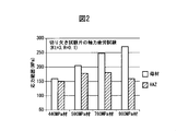
- the cause of the decrease in fatigue strength of the welded portion of the high-strength steel plate is considered to be an adverse effect on the fatigue strength of the welded portion due to HAZ material deterioration caused by fillet arc welding. Therefore, a thermal cycle during welding was applied to a steel sheet having a tensile strength of 440 to 980 Mp, and the fatigue strength of the base material and the fatigue strength of the weld heat affected zone were compared and investigated.
- the heat treatment conditions for reproducing the HAZ are a maximum attained temperature of 1200 ° C., and cooling rates at 1200 ° C. to 800 ° C., 800 ° C. to 500 ° C., 500 ° C.
- the fatigue test piece was provided with a notch with a stress concentration factor (Kt) of 3.
- Figure 2 shows the fatigue test results.
- the fatigue strength of HAZ is reduced in a high-strength steel plate compared to the base material.
- a fillet arc welded joint excellent in fatigue strength in which the heat-affected zone (HAZ) region in the plate thickness direction, which is the direction of crack propagation, is narrowed and crack propagation is suppressed, and a method for manufacturing the same are disclosed.
- the purpose is to provide.
- laser light is used for processing the toe portion of fillet arc welding.
- the region including the boundary between the weld toe and the heat-affected zone generated by the fillet arc welding is remelted with laser light and locally hardened and hardened ( Hereinafter, it is referred to as “local quenching by laser”).
- the present inventors suppress the crack from the fillet arc welding toe portion by the remelting using the laser beam, and the remelted region (remelting portion) that becomes the crack generation position after the laser irradiation. ) It was found that by narrowing the HAZ 6a at the melt boundary 6b of 6, it becomes possible to suppress the progress of the crack 4, and a significant improvement in weld fatigue strength can be achieved.
- the present invention has been made based on the above findings, and the gist thereof is as follows.
- the fillet arc welded joint of the present invention is a fillet arc welded joint formed by performing fillet arc welding of at least two metal members, and the weld toe of the fillet arc welding of at least one metal member. And a region including the boundary of the heat affected zone generated by the fillet arc welding on the surface of the metal member has a remelted portion by laser irradiation, the remelted portion from the surface of the metal member It is a range up to a depth of 1 ⁇ 2 or less of the plate thickness of the metal member, and is 0.1 mm in the plate thickness direction of the metal member from the remelt boundary portion which is the boundary of the remelt portion on the surface of the metal member.
- the average effective grain size of the prior austenite in the heat affected zone at the depth is 20 ⁇ m or less.
- the remelted portion may be in a range from the surface of the metal member to a depth of 1/3 or less of the plate thickness of the metal member.
- the weld metal of the remelted portion may have a Ceq value defined by the following formula (1) of 0.3 or more.
- Ceq C + Mn / 6 + Si / 24 + Ni / 40 + Cr / 5 + Mo / 4 + V / 14 Formula (1);
- C, Mn, Si, Ni, Cr, Mo, and V indicate element content (mass%), and 0 is substituted in the case of an additive-free element.
- the depth of the remelted portion in the thickness direction of the metal member is 1/5 or more of the thickness of the metal member from the surface of the metal member.
- the hardness of the boundary portion between the laser remelting portion and the heat affected zone at a position 0.1 mm below the steel sheet surface is 1.2 times or more of the hardness of the base material of the metal member, and the boundary portion
- the hardness of the metal member at a depth of 1/4 of the plate thickness of the metal member from the surface of the steel plate in the vertically downward direction may be 1.1 times or less of the hardness of the base material of the metal member.
- the metal member may be a steel plate having a thickness of 4.5 mm or less.
- a remelted portion may be formed in at least one location where a high stress obtained in advance is applied.
- the method for manufacturing a fillet arc welded joint according to the present invention includes fillet arc welding of at least two metal members, the weld toe of the fillet arc welding of at least one metal member, and the surface of the metal member. Remelting the region including the boundary of the heat affected zone caused by fillet arc welding by laser irradiation to form a remelted zone from the surface of the metal member to a depth of 1/2 or less of the plate thickness of the metal member.
- the average effective of prior austenite in the heat-affected zone at a depth of 0.1 mm from the remelt boundary in the thickness direction of the metal member may be 20 ⁇ m or less.
- the remelted region is in a range from the surface of the metal member to a depth of 1/3 or less of the plate thickness of the metal member. There may be.
- a Ceq value defined by the following formula (1) of the remelted metal member may be 0.3 or more.
- Ceq C + Mn / 6 + Si / 24 + Ni / 40 + Cr / 5 + Mo / 4 + V / 14 Formula (1);
- C, Mn, Si, Ni, Cr, Mo, and V indicate element content (mass%), and 0 is substituted in the case of an additive-free element.
- the depth of the remelted portion from the surface of the metal member is 1/5 or more of the plate thickness of the metal member, and the steel plate surface
- the hardness at the boundary between the laser remelted portion and the heat-affected zone at a position 0.1 mm below the plate thickness direction is 1.2 times or more the hardness of the base material of the metal member, and is perpendicular to the boundary.
- Laser irradiation may be performed so that the hardness at a depth of 1/4 of the thickness of the metal member from the steel plate surface in the downward direction is 1.1 times or less the hardness of the base material of the metal member.
- the metal member may be a steel plate having a thickness of 4.5 mm or less.
- At least one place where a high stress obtained in advance is applied may be remelted by laser irradiation.
- the laser irradiation has a ratio of a laser output (kJ / sec) to a moving speed (m / min) of 45 to 80 (kJ / m). It may be.
- the present invention it is possible to improve the fatigue strength of the weld toe portion of the high-tensile steel having a tensile strength of 980 MPa and to narrow the HAZ in the plate thickness direction. Therefore, the fatigue strength of arc welded joints of thin steel plates such as automobile steel plates can be increased.
- FIG. 5 is a graph showing the relationship between the number of repeated fatigue tests, the strain change rate, and the crack growth. It is the graph which produced the welding test piece which changed the remelting part depth, and calculated
- FIG. 6A shows the relationship between the average effective grain size of prior austenite and the fatigue strength improvement rate in the heat-affected zone, obtained by observing the metal structure of the weld toe or laser melting end of the test piece used in the experiment of FIG. 6A. It is a graph to show. It is a graph which shows the Vickers hardness of the plate thickness direction in the welding toe part of the conventional fillet arc welded joint and the fillet arc welded joint of this invention by laser irradiation. The Vickers hardness is expressed as a ratio to the Vickers hardness of the base material.
- FIG. 8 is an enlarged cross-sectional view showing a portion where the Vickers hardness shown in the graph of FIG. 7 is measured.
- FIG. 7A corresponds to the “conventional” graph of FIG. ".
- the present invention is a technique aimed at suppressing the progress of cracks by narrowing the HAZ in the plate thickness direction, the effect of improving the fatigue strength varies depending on the laser quenching conditions. Therefore, as a preliminary evaluation, the relationship between laser irradiation conditions and fatigue strength was investigated.
- the test material was a 980 MPa grade steel plate having a thickness of 2.3 mm
- the arc welding material was a welding material for 780 MPa grade steel (JIS Z3312 G78A4UMN5C1M3T).
- Arc welding with Parusumagu welding, the shielding gas and Ar + 20% CO 2
- the welding current 190A, arc voltage 24V the condition of the welding speed 80 cm / min.
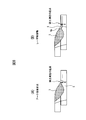
- Laser irradiation conditions for laser quenching were set at two levels of +10 mm defocus and +15 mm defocus, aiming at the toe part of fillet arc welding with a laser output of 3 kW and a moving speed of 3 m / min.
- FIG. 4 shows the cross-sectional melt shape of the welded part when quenched with (A) no laser irradiation, (B) +10 mm defocus, and (C) +15 mm defocus.
- the Vickers hardness at the melting boundary without laser quenching was 250 HV, but the hardness at the corresponding location increased to 382 HV by laser quenching.
- the remelted region (the region indicated by the arrows in FIGS. 4B and 4C and corresponding to the remelting portion 6 in FIG. 3) is obtained by cutting and polishing the sample. It can be observed by etching.
- Table 1 shows the fatigue life of the specimen after the local quenching.
- the fatigue life of the test piece was measured by performing a one-side bending test with a stress amplitude of 250 MPa on the weld toe of the test piece.
- condition C is slower in crack generation and the crack propagation speed is slower than the condition A.
- the growth path of cracks is not a HAZ but a base material composed of a fine grain structure.
- the heat input region is reduced as the melting region is reduced by the laser. This is probably because the tensile residual stress decreased as a result of the reduction.
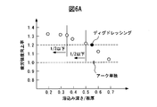
- a weld specimen having a remelted portion depth changed in the same manner as in FIG. 4 is prepared, and arc welding alone (ie, arc welding).
- the relationship between the remelted penetration depth and the improvement rate of joint fatigue strength was obtained experimentally.
- the result is shown in FIG. 6A.
- FIG. 6A when the crack generation depth becomes larger than 1 / 2t (1/2 thickness of the plate thickness t), the same effect as that when Tig dressing is performed is obtained.
- the penetration depth of the remelted portion is shallow, the surface of the remelted portion becomes uneven, so that the remelt depth is 1/5 or more and 1 / 2t or less, preferably 1/5 or more and 1 / 3t. It is as follows.
- the thickness of the steel sheet from the boundary between the remelted portion on the steel plate surface and the heat affected zone of the remelted portion (hereinafter referred to as “remelted boundary portion”).
- the metal structure at a depth of 0.1 mm in the direction was observed.
- the remelted portion at a depth of 0.1 mm in the plate thickness direction starting from the boundary between the weld metal and the heat affected zone on the steel plate surface was observed.
- EBSD analysis was performed on a metal structure in a range of 500 ⁇ m ⁇ 500 ⁇ m centering on the above-mentioned position, and the average effective crystal grain size of prior austenite was obtained from the crystal grain size when the crystal orientation difference was 15 °.
- Old austenite which is a target for measuring the effective crystal grain size, is not included in the remelted portion, but is included in the heat affected zone of the remelted portion by the laser irradiation.
- FIG. 6B shows the relationship between the average effective crystal grain size of the prior austenite in the heat-affected zone and the fatigue strength improvement rate.
- the fatigue strength of arc welding alone was set to 1.0.
- the fatigue strength increased with a decrease in penetration depth, but in FIG. 6B, it can be seen that the fatigue strength increases with a decrease in crystal grain size.
- the average effective crystal grain size of old austenite by arc welding alone was 37 ⁇ m
- the average effective crystal grain size of old austenite when TIG dressing was applied was 32 ⁇ m.
- the fatigue strength improvement rate more than Tig dressing can be obtained by making the average effective crystal grain size of prior austenite contained in the heat-affected zone of the remelted zone by laser treatment 20 ⁇ m or less. Was confirmed.
- TIG dressing has a fatigue strength improvement rate of 1.2 times despite the crystal grain size being relatively large, this is because the weld toe was remelted with a relatively large amount of heat. This is probably because the shape of the end became smooth and the stress concentration factor became a smaller value.
- the conventional TIG dressing and plasma processing techniques are characterized by an action mechanism that reduces stress concentration on the weld toe, which is a crack generating part, by smoothing the shape of the molten end.
- the present invention is characterized by an action mechanism in which the metal structure of the crack generation part is refined by laser processing to improve fatigue strength, and the technical idea is different from conventional techniques such as Tig dressing. It is.
- the laser irradiation is performed under irradiation conditions such as laser irradiation intensity, laser irradiation time, and irradiation range so as to satisfy the following (i) and (ii). It is preferable to adjust.
- the hardness of the fusion boundary newly formed by laser remelting at a position 0.1 mm below the surface of the steel sheet in the thickness direction is increased to 1.2 times or more of the hardness of the base material;
- the hardness at the depth position of about 1 ⁇ 4 of the steel sheet from the surface of the steel sheet in the vertical downward direction of the melting boundary at a position 0.1 mm below the surface of the steel sheet in the thickness direction is the hardness of the base material. 1.1 times or less.
- the conventional fillet arc welded joint has a hardness distribution in the region of 0.1 mm thickness, the hardness is not increased, and the region of 1/4 thickness. The hardness is not softened.
- the distribution of hardness in the thickness direction is a preferable distribution for crack suppression.
- FIG. 8A is an enlarged cross-sectional view of an arc welded portion where remelting by laser irradiation has not been performed
- FIG. 8B is an arc weld based on the fillet arc welded joint manufacturing method of the present invention. It is an expanded sectional view of the location where was performed.
- FIG. 8A the hardness distribution in the plate thickness direction was measured along the arrow direction starting from the boundary between the weld metal 3 and the heat affected zone 5 0.1 mm below the steel plate surface.
- FIG. 8A the hardness distribution in the plate thickness direction was measured along the arrow direction starting from the boundary between the weld metal 3 and the heat affected zone 5 0.1 mm below the steel plate surface.
- the hardness distribution in the thickness direction was measured along the arrow direction starting from the boundary between the laser remelting portion 6 and the heat-affected zone 6a 0.1 mm below the steel sheet surface.
- the base material hardness was measured at a location sufficiently away from the arrow line in FIGS. 8 (A) and 8 (B).
- the present invention locally quenches the weld toe portion by laser irradiation.
- a steel member having a composition in which the Ceq value defined by the formula (1) is 0.3 or more.
- Ceq C + Mn / 6 + Si / 24 + Ni / 40 + Cr / 5 + Mo / 4 + V / 14 Formula (1);
- C, Mn, Si, Ni, Cr, Mo, and V show element content (mass%).
- a welding material having a composition with a Ceq value defined by the above formula (1) of 0.3 or more is used. It is preferable.
- a melting part may be formed in a region where a fatigue crack first occurs when a repeated load assumed to be applied to a welded structural member to which an external load is directly applied is applied to the welded structural member.
- a melting part may be formed in a region where a fatigue crack first occurs when a repeated load assumed to be applied to a welded structural member to which an external load is directly applied is applied to the welded structural member.
- the remelted portion in the present invention may be formed at a weld location where the maximum principal stress is generated. As described above, it is effective to improve the fatigue strength to form the remelted portion in at least one place where the high stress obtained in advance is applied.
- test piece was prepared as follows, and the weld toe of the arc weld bead of the test piece was prepared as follows.
- the part was irradiated with a laser beam, and the Vickers hardness, fatigue strength, fatigue strength improvement rate, and average effective crystal grain size of prior austenite were measured for the test piece after laser irradiation.
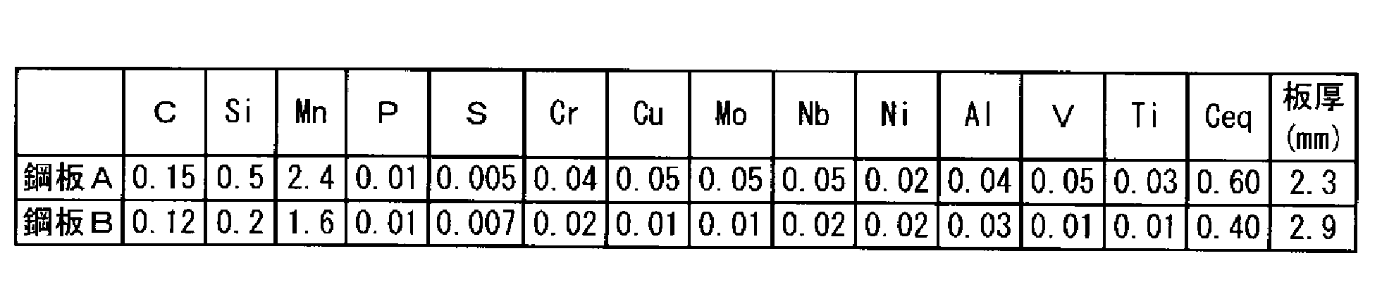
- Table 2-1 shows the components (mass%) of the test steel sheet.
- Steel plate A is a 980 MPa grade hot-rolled steel plate and steel plate B is a 780 MPa grade hot-rolled steel plate, both having a Ceq of 0.3 or more.
- the plate thickness of the steel plate A is 2.3 mm, and the plate thickness of the steel plate B is 2.9 mm.
- Table 2-2 shows the components of the welding wire.
- w1 is a welding wire for a 490 MPa class steel plate
- w2 is a welding wire for a 780 MPa class steel plate
- the Ceq of w1 is less than 0.3
- the Ceq of w2 is 0.3 or more.
- the outer diameter of each wire is 1.2 mm.
- a lap fillet joint was produced by pulse mag welding using these steel plates and welding wires.
- the welding conditions were welding current: 190 A, arc voltage: 24 V, welding speed: 0.8 m / min for a joint with a plate thickness of 2.3 mm, and welding speed: 0.6 m / min for a joint with a plate thickness of 2.9 mm. .
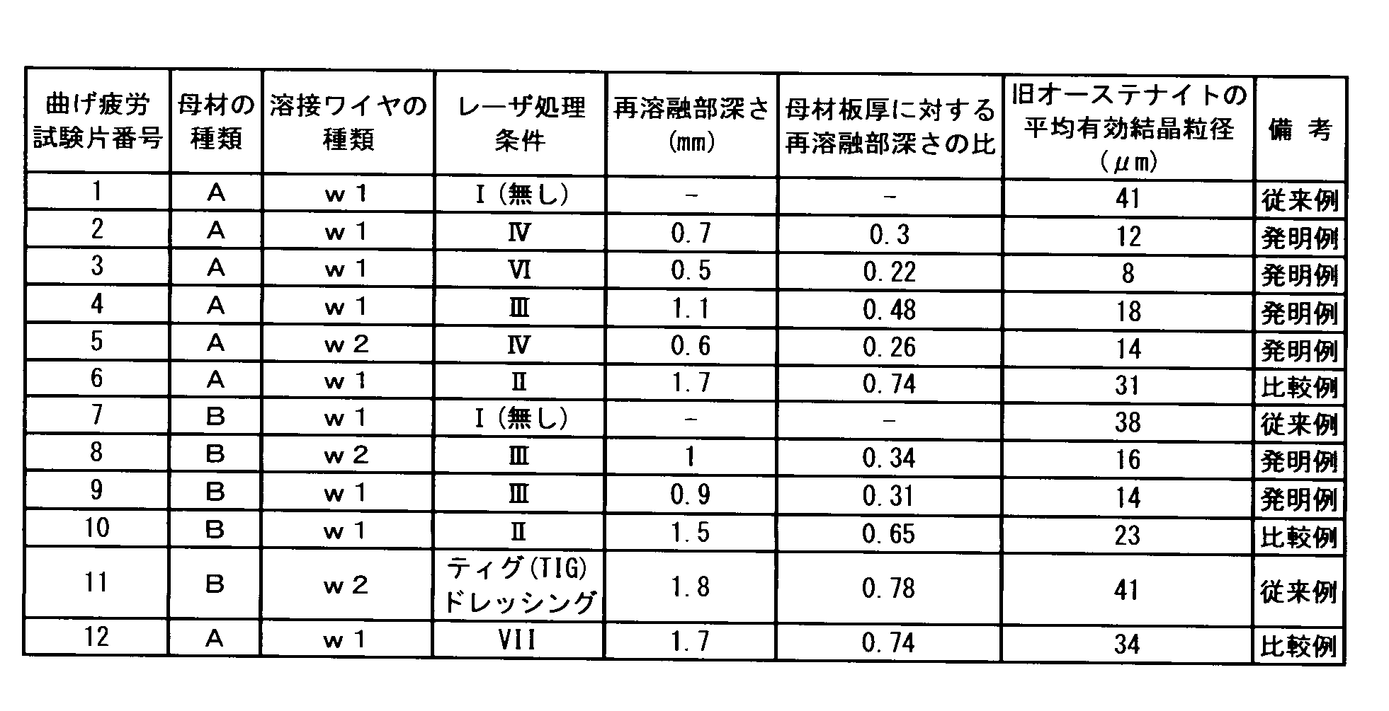
- Condition I is a case where no laser treatment is performed, conditions II to VI are YAG laser processing apparatus, laser output is 3 to 4 kW, defocus length is +5 to +15 mm, and moving speed is 3 to 4 m / min.
- the lens of the laser processing apparatus has a condensing diameter of 0.6 mm and a focal length of 200 mm.
- Condition III is about 1/2 the penetration depth, and Conditions IV to VI are about 1/3 the thickness. It was the penetration depth.
- Bending fatigue test specimen No. 1 was combined with the steel plate in Table 2-1, the welding wire in Table 2-2, and the laser processing conditions in Table 2-3 under the conditions in Table 3-1. 1 to 11 were prepared, and the fatigue strength and fatigue strength improvement rate were measured.
- fatigue test piece No. For each of 1 to 11, Vickers hardness, fatigue strength, fatigue strength improvement rate, and average effective crystal grain size of prior austenite of the metal structure near the welded portion were measured.
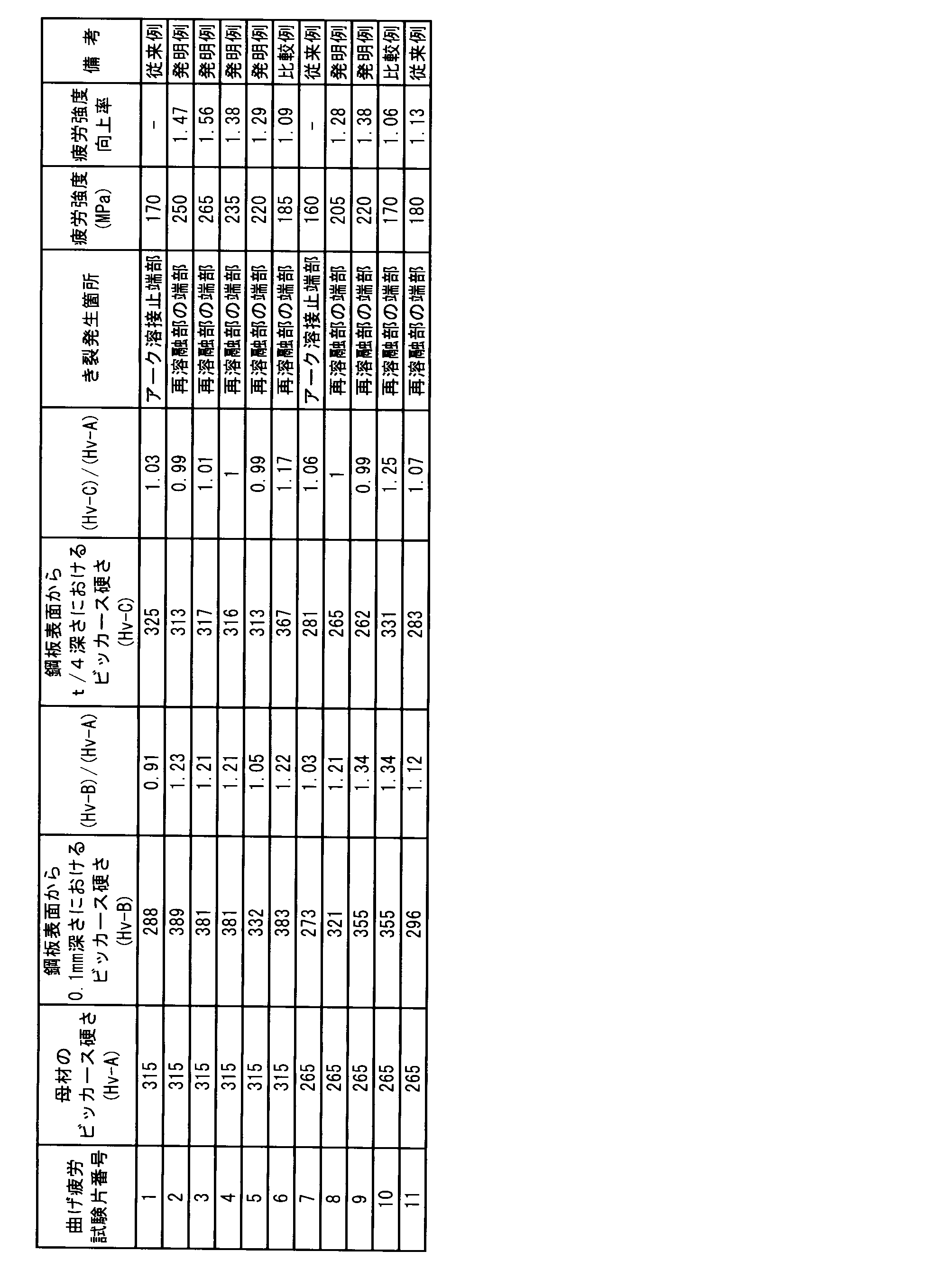
- the fatigue strength measurement test is performed with a single swing using a Schenck fatigue tester, and the number of repetitions is up to 2 million times. For each of the fatigue test pieces, the crack occurrence location and the 2 million times fatigue strength ( Stress amplitude) was measured. The results are shown in Table 3-2.
- Fatigue test piece No. No. 1 corresponds to a conventional lap fillet arc welded joint using a combination of a 980 MPa class hot rolled steel sheet A and a welding wire w1 for a 490 MPa class steel sheet, and its fatigue strength was 170 MPa.
- fatigue test piece No. 7 corresponds to a conventional lap fillet arc welded joint by a combination of a 780 MPa class hot rolled steel sheet B and a welding wire w1 for a 490 MPa class steel sheet, and its fatigue strength was 160 MPa.
- the base material used was a fatigue test piece no. No. 1 fatigue test piece No. 1 For 2-6, fatigue test specimen No.
- the fatigue strength improvement rate based on the fatigue strength of 1 was calculated.
- the base material used was fatigue test piece No. No. 7 same fatigue test piece No. For 8 to 11, fatigue test specimen No.
- the fatigue strength improvement rate based on the fatigue strength of 7 was calculated. From the result of the fatigue strength improvement rate of each fatigue test piece calculated in this way, the fatigue strength improvement effect by laser toe treatment was evaluated.
- the “Vickers hardness (Hv-A) of the base metal” in Table 3-2 is a measured value of the surface hardness of the steel plate before welding, welding by Tig dressing, and remelting by laser.
- the fatigue test pieces 2 and 3 satisfied the most suitable conditions of the present invention, and the best results were obtained in the fatigue strength or the fatigue strength improvement rate.
- the fatigue test piece 4 is better in both fatigue strength and fatigue strength improvement rate than the conventional example, but since the remelting depth by laser is more than 1/3 of the plate thickness, the crack is along the HAZ.
- the fatigue strength and the fatigue strength improvement rate are slightly inferior to those of the fatigue test pieces 2 and 3.
- the fatigue test piece 5 is also better than the conventional example in both fatigue strength and fatigue strength improvement rate, but because it was made using a welding wire having a Ceq of less than 0.3, it was 0.1 mm deep from the steel sheet surface. The local quenching in was insufficient. Therefore, compared with the fatigue test pieces 2 and 3, the fatigue strength and the fatigue strength improvement rate are slightly inferior.
- the fatigue test piece 8 is better in both fatigue strength and fatigue strength improvement rate than the fatigue test pieces 7 and 11 as the conventional examples and the fatigue test piece 10 as the comparative example.
- the fatigue test piece 11 corresponds to a conventional lap fillet arc welded joint manufactured using a conventional TIG dressing, and melts so that the remelting depth by laser exceeds 70% of the plate thickness. However, since the crack propagated in the HAZ, a sufficient fatigue strength improvement effect could not be obtained.
- the fatigue test piece 11 had a large penetration depth, that is, a large heat input, so that the HAZ was large and the fatigue strength was insufficient because the crack propagated only in the HAZ.
- the fatigue test piece 8 was produced using a welding wire having a Ceq of less than 0.3, the local quenching at a depth of 0.1 mm from the steel sheet surface was about 10% compared to the fatigue test piece 9. The strength is low.
- the fatigue test piece 9 is manufactured so that the remelting depth by laser is less than 1/3 of the plate thickness, and both the fatigue strength and the fatigue strength improvement rate are better than the fatigue test piece 8. Yes.
- Fatigue test piece 10 has the shortest defocus length, laser remelting depth has reached more than 1/2 the plate thickness, deep penetration, and cracks have propagated in the HAZ, resulting in sufficient fatigue strength improvement. The effect was not obtained.
- the present invention has high applicability in the welding industry using high-strength thin steel plates.
Landscapes
- Engineering & Computer Science (AREA)
- Chemical & Material Sciences (AREA)
- Mechanical Engineering (AREA)
- Materials Engineering (AREA)
- Metallurgy (AREA)
- Organic Chemistry (AREA)
- Physics & Mathematics (AREA)
- Plasma & Fusion (AREA)
- Optics & Photonics (AREA)
- Thermal Sciences (AREA)
- Crystallography & Structural Chemistry (AREA)
- Butt Welding And Welding Of Specific Article (AREA)
- Laser Beam Processing (AREA)
- Heat Treatment Of Articles (AREA)
Abstract
Description
また、TIGアーク熱源やプラズマ熱源で溶接ビードを再溶融すると、薄板部材では入熱過多となるためHAZの材質が劣化して疲労強度を低下させるという問題がある。
Ceq=C+Mn/6+Si/24+Ni/40+Cr/5+Mo/4+V/14・・・式(1);
但し、式(1)中、C、Mn、Si、Ni、Cr、Mo、Vは、元素の含有量(質量%)を示し、無添加の元素の場合、0が代入される。
Ceq=C+Mn/6+Si/24+Ni/40+Cr/5+Mo/4+V/14・・・式(1);
但し、式(1)中、C、Mn、Si、Ni、Cr、Mo、Vは、元素の含有量(質量%)を示し、無添加の元素の場合、0が代入される。
そこで、予備評価として、レーザ照射条件と疲労強度の関係を調査した。供試材は板厚2.3mmの980MPa級鋼板とし、アーク溶接材料には780MPa級鋼用の溶接材料(JIS Z3312 G78A4UMN5C1M3T)を使用した。アーク溶接は、パルスマグ溶接で、シールドガスをAr+20%CO2とし、溶接電流190A、アーク電圧24V、溶接速度80cm/minの条件とした。

このように、溶接止端部をレーザで溶融することによって当該止端部が焼き入れされて硬化し、溶接部分の疲労強度が上昇するが、レーザ照射条件、すなわち溶融形状の違いによっても大きな疲労強度差が生じることが分かる。
条件A:アーク溶接のみを行った場合;
条件B:レーザによる再溶融深さが板厚の1/2程度になるようにした場合;
条件C:レーザによる再溶融深さが板厚の1/3程度になるようにした場合
(i)鋼板の表面から板厚方向に0.1mm下の位置におけるレーザ再溶融によって新たに形成される溶融境界の硬度を母材の硬さの1.2倍以上に高める;
(ii)鋼板の表面から板厚方向に0.1mm下の位置における前記溶融境界の垂直下方向において、鋼板の表面から前記鋼板の約1/4の深さ位置における硬度を母材の硬度の1.1倍以下にする。
但し、母材硬さは、図8(A)、(B)中の矢印線から十分離れた箇所において測定した。
Ceq=C+Mn/6+Si/24+Ni/40+Cr/5+Mo/4+V/14・・・式(1);
但し、式(1)中、C、Mn、Si、Ni、Cr、Mo、Vは、元素の含有量(質量%)を示す。


疲労強度測定試験は、シェンク式疲労試験機を用いて完全片振りで実施し、繰返し数は200万回までとし、前記疲労試験片のそれぞれについて、亀裂の発生箇所と、200万回疲労強度(応力振幅)を測定した。その結果を表3-2に示す。
疲労試験片No.1は、980MPa級熱延鋼板Aと490MPa級鋼板用の溶接ワイヤw1の組み合わせによる従来の重ね隅肉アーク溶接継手に相当するものであり、その疲労強度は170MPaであった。また、疲労試験片No.7は、780MPa級の熱延鋼板Bと490MPa級鋼板用の溶接ワイヤw1の組み合わせによる従来の重ね隅肉アーク溶接継手に相当するものであり、その疲労強度は160MPaであった。使用した母材が疲労試験片No.1と同じ疲労試験片No.2~6に対しては、疲労試験片No.1の疲労強度を基準とした疲労強度向上率を算出した。また、使用した母材が疲労試験片No.7と同じ疲労試験片No.8~11に対しては、疲労試験片No.7の疲労強度を基準とした疲労強度向上率を算出した。このように算出された各疲労試験片の疲労強度向上率の結果から、レーザ止端処理による疲労強度向上効果を評価した。
条件II~VIでレーザ処理された試験片について、鋼板表面から板厚方向に0.1mm下の位置における再溶融境界部におけるビッカース硬さを測定した。尚、条件I或いはティグドレッシングによる溶接が行われた試験片について、鋼板表面における溶接金属と熱影響部の境界部を起点に板厚方向に0.1mm深さにおけるビッカース硬さを測定した。各試験片の測定値を表3-2の「鋼板表面から0.1mm深さにおけるビッカース硬さ(Hv-B)」の欄に示す。尚、熱影響部、溶接部及び再溶融部から十分離れた箇所における鋼板表面硬度を測定した。尚、表3-2の「母材のビッカース硬さ(Hv-A)」は、溶接、ティグドレッシングによる溶接及びレーザによる再溶融が行われる前の鋼板の表面硬度の測定値である。
条件II~VIでレーザ処理された試験片について、鋼板表面上の再溶融境界部から鋼板の板厚方向に0.1mmの深さにおける金属組織を観察した。条件I或いはティグドレッシングによる溶接が行われた試験片について、鋼板表面における溶接金属と熱影響部の境界部を起点に板厚方向に0.1mm深さにおける金属組織を観察した。前述した位置を中心に500μm×500μmの範囲の金属組織をEBSD解析し、結晶方位差15°で区切ったときの結晶粒サイズから旧オーステナイトの平均有効結晶粒径を求めた。この測定結果を、表3-2の項目「旧オーステナイトの平均有効結晶粒径(μm)」の欄に示す。
疲労試験片2、3は本発明の最も好適な条件を満足しており、疲労強度或いは疲労強度向上率が最も良好な結果が得られた。疲労試験片4は疲労強度及び疲労強度向上率とも従来例に比べて良好であるが、レーザによる再溶融深さが板厚の1/3超と溶け込みが深いために、き裂がHAZに沿って進展する傾向を示し、疲労試験片2、3に比べると疲労強度及び疲労強度向上率が若干劣る。また、疲労試験片5も疲労強度及び疲労強度向上率とも従来例に比べて良好であるが、Ceqが0.3未満の溶接ワイヤを用いて作製されたために、鋼板表面から0.1mm深さにおける前記局所焼き入れが不十分となった。そのため、疲労試験片2、3に比べると疲労強度及び疲労強度向上率が若干劣る。
曲げ疲労試験片6は、デフォーカス長さが最も短く、レーザによる再溶融深さが板厚の1/2超に達していたため、き裂がHAZ内を進展した。その結果、疲労強度が向上せず十分な疲労強度向上効果が得られなかった。
疲労試験片8は、疲労強度及び疲労強度向上率とも、従来例としての疲労試験片7、11及び比較例としての疲労試験片10に比べて良好である。尚、疲労試験片11は従来技術のティグドレッシングを用いて作製された従来の重ね隅肉アーク溶接継手に相当するものであり、レーザによる再溶融深さが板厚の70%を超える程度に溶け込みが深く、き裂がHAZ内を進展したため、十分な疲労強度向上効果が得られなかった。疲労試験片11は、溶け込み深さが大きい、すなわち、入熱が大きいため、HAZが大きくなり、き裂がHAZ内のみを進展するために疲労強度が不十分となった。
疲労試験片10はデフォーカス長さが最も短く、レーザによる再溶融深さが板厚の1/2超に達しており、溶け込みが深く、き裂がHAZ内を進展したため、十分な疲労強度向上効果が得られなかった。
2 下板
3 溶接ビード
4 亀裂
5 HAZ(熱影響部)
6 レーザ再溶融部
6a レーザ溶融によるHAZ
Claims (14)
- 少なくとも2つの金属部材を隅肉アーク溶接することにより形成された隅肉アーク溶接継手であって、
少なくとも一つの金属部材の前記隅肉アーク溶接の溶接止端部と、当該金属部材の表面の前記隅肉アーク溶接によって生じた熱影響部の境界を含める領域に、レーザ照射による再溶融部を有し、
前記再溶融部は、前記金属部材の表面から当該金属部材の板厚の1/2以下の深さまでの範囲であって、
前記金属部材の表面における前記再溶融部の境界である再溶融境界部から前記金属部材の板厚方向に0.1mmの深さでの熱影響部における旧オーステナイトの平均有効結晶粒径は、20μm以下であることを特徴とする隅肉アーク溶接継手。
- 前記再溶融部が、前記金属部材の表面から当該金属部材の板厚の1/3以下の深さまでの範囲であることを特徴とする請求項1に記載の隅肉アーク溶接継手。
- 前記再溶融部の溶接金属は、以下の式(1)で定義されるCeq値が0.3以上であることを特徴とする請求項1又は2に記載の隅肉アーク溶接継手。
Ceq=C+Mn/6+Si/24+Ni/40+Cr/5+Mo/4+V/14・・・式(1);
但し、式(1)中、C、Mn、Si、Ni、Cr、Mo、Vは、元素の含有量(質量%)を示す。
- 前記再溶融部の前記金属部材の板厚方向の深さは、前記金属部材の表面から前記金属部材の板厚の1/5以上であり、
鋼板表面から0.1mm下の位置におけるレーザ再溶融部と熱影響部との境界部の硬度が、前記金属部材の母材の硬度の1.2倍以上であって、前記境界部の垂直下方向において鋼板表面から前記金属部材の板厚の1/4深さにおける前記金属部材の硬度が、前記金属部材の母材の硬度の1.1倍以下であることを特徴とする請求項1~3のうちいずれか1項に記載の隅肉アーク溶接継手。
- 前記金属部材は、板厚が4.5mm以下の鋼板であることを特徴とする請求項1~4のうちいずれか1項に記載の隅肉アーク溶接継手。
- 予め求めた高い応力が負荷される箇所の少なくとも1つの箇所に、再溶融部が形成されていることを特徴とする請求項1~5のうちいずれか1項に記載の隅肉アーク溶接継手。
- 少なくとも2つの金属部材を隅肉アーク溶接し、
少なくとも一つの金属部材の前記隅肉アーク溶接の溶接止端部と、当該金属部材の表面の前記隅肉アーク溶接によって生じた熱影響部の境界を含める領域をレーザ照射により再溶融し、前記金属部材の表面から金属部材の板厚の1/2以下の深さまで再溶融部を形成することを特徴とする隅肉アーク溶接継手の製造方法。
- 前記再溶融境界部から前記金属部材の板厚方向に0.1mmの深さでの熱影響部における旧オーステナイトの平均有効結晶粒径が、20μm以下であることを特徴とする請求項7に記載の隅肉アーク溶接継手の製造方法。
- 前記再溶融された領域が、前記金属部材の表面から前記金属部材の板厚の1/3以下の深さまでの範囲であることを特徴とする請求項7又は8に記載の隅肉アーク溶接継手の製造方法。
- 前記再溶融されている金属部材は、以下の式(1)で定義されるCeq値が0.3以上であることを特徴とする請求項7~9のうちいずれか1項に記載の隅肉アーク溶接継手の製造方法。
Ceq=C+Mn/6+Si/24+Ni/40+Cr/5+Mo/4+V/14・・・式(1);
但し、式(1)中、C、Mn、Si、Ni、Cr、Mo、Vは、元素の含有量(質量%)を示す。
- 前記再溶融部の前記金属部材の表面からの深さは前記金属部材の板厚の1/5以上であり、
鋼板表面から板厚方向に0.1mm下の位置におけるレーザ再溶融部と熱影響部との境界部における硬度が、前記金属部材の母材の硬度の1.2倍以上であって、前記境界部の垂直下方向において鋼板表面から前記金属部材の板厚の1/4深さにおける硬度が、前記金属部材の母材の硬度の1.1倍以下になるように、レーザ照射を行うことを特徴とする請求項7~10のうちいずれか1項に記載の隅肉アーク溶接継手の製造方法。
- 前記金属部材は、板厚が4.5mm以下の鋼板であることを特徴とする請求項7~11のうちいずれか1項に記載の隅肉アーク溶接継手の製造方法。
- 予め求めた高い応力が負荷される箇所の少なくとも1つの箇所を、レーザ照射により再溶融することを特徴とする請求項7~12のうちいずれか1項に記載の隅肉アーク溶接継手の製造方法。
- 前記レーザ照射は、移動速度(m/min)に対するレーザ出力(kJ/sec)の比が45~80(kJ/m)であることを特徴とする請求項7~13のうちいずれか1項に記載の隅肉アーク溶接継手の製造方法。
Priority Applications (5)
| Application Number | Priority Date | Filing Date | Title |
|---|---|---|---|
| US15/748,059 US10786873B2 (en) | 2015-07-28 | 2016-07-28 | Fillet arc welded joint and method for producing same |
| CN201680044108.8A CN108025401B (zh) | 2015-07-28 | 2016-07-28 | 电弧角焊接头及其制造方法 |
| JP2017530928A JP6515299B2 (ja) | 2015-07-28 | 2016-07-28 | 隅肉アーク溶接継手及びその製造方法 |
| MX2018001077A MX2018001077A (es) | 2015-07-28 | 2016-07-28 | Junta soldada por arco en angulo y metodo para producir la misma. |
| KR1020187001820A KR102020927B1 (ko) | 2015-07-28 | 2016-07-28 | 필릿 아크 용접 조인트 및 그 제조 방법 |
Applications Claiming Priority (2)
| Application Number | Priority Date | Filing Date | Title |
|---|---|---|---|
| JP2015-148634 | 2015-07-28 | ||
| JP2015148634 | 2015-07-28 |
Publications (1)
| Publication Number | Publication Date |
|---|---|
| WO2017018492A1 true WO2017018492A1 (ja) | 2017-02-02 |
Family
ID=57884510
Family Applications (1)
| Application Number | Title | Priority Date | Filing Date |
|---|---|---|---|
| PCT/JP2016/072220 Ceased WO2017018492A1 (ja) | 2015-07-28 | 2016-07-28 | 隅肉アーク溶接継手及びその製造方法 |
Country Status (6)
| Country | Link |
|---|---|
| US (1) | US10786873B2 (ja) |
| JP (1) | JP6515299B2 (ja) |
| KR (1) | KR102020927B1 (ja) |
| CN (1) | CN108025401B (ja) |
| MX (1) | MX2018001077A (ja) |
| WO (1) | WO2017018492A1 (ja) |
Cited By (8)
| Publication number | Priority date | Publication date | Assignee | Title |
|---|---|---|---|---|
| WO2018159719A1 (ja) | 2017-02-28 | 2018-09-07 | 新日鐵住金株式会社 | 隅肉溶接継手及びその製造方法 |
| WO2018203513A1 (ja) * | 2017-05-01 | 2018-11-08 | 株式会社神戸製鋼所 | アーク溶接方法及び溶接ワイヤ |
| JP2019084544A (ja) * | 2017-11-02 | 2019-06-06 | 日産自動車株式会社 | 溶接構造体、および溶接構造体の製造方法 |
| JP2019516556A (ja) * | 2016-06-01 | 2019-06-20 | ポスコPosco | 疲労特性が優秀な溶接継手およびその製造方法 |
| WO2019124871A1 (ko) * | 2017-12-20 | 2019-06-27 | 주식회사 포스코 | 피로특성이 우수한 초고강도 열연강재의 용접이음부 및 그 제조방법 |
| KR20190110110A (ko) * | 2017-02-28 | 2019-09-27 | 제이에프이 스틸 가부시키가이샤 | 겹치기 필렛 아크 용접 이음매 및 그 제조 방법 |
| JP2021074740A (ja) * | 2019-11-07 | 2021-05-20 | 日本製鉄株式会社 | 溶接継手、及び自動車部品 |
| CN116135398A (zh) * | 2021-11-16 | 2023-05-19 | 通快(中国)有限公司 | 改善方法、焊接方法、加工系统、控制装置、程序产品 |
Families Citing this family (6)
| Publication number | Priority date | Publication date | Assignee | Title |
|---|---|---|---|---|
| JP7119960B2 (ja) * | 2018-12-03 | 2022-08-17 | 日本軽金属株式会社 | 接合方法 |
| DE102019208337A1 (de) * | 2019-06-07 | 2020-12-10 | MTU Aero Engines AG | Gasturbinen-Impulskörpermodul |
| CN110773894B (zh) * | 2019-10-09 | 2021-07-09 | 东方电气集团东方汽轮机有限公司 | 一种大拘束度结构组件的焊接热影响区再热裂纹控制方法 |
| KR102872957B1 (ko) | 2020-03-31 | 2025-10-17 | 현대자동차주식회사 | T형 용접 이음매의 접합 구조 |
| JP7328181B2 (ja) | 2020-07-15 | 2023-08-16 | 株式会社神戸製鋼所 | 重ねすみ肉溶接継手及びその製造方法並びに閉断面部材 |
| CN117754130A (zh) * | 2024-01-22 | 2024-03-26 | 中煤北京煤矿机械有限责任公司 | 一种采用激光进行mag焊缝焊趾重熔的方法 |
Citations (2)
| Publication number | Priority date | Publication date | Assignee | Title |
|---|---|---|---|---|
| JP4477707B2 (ja) * | 1999-03-10 | 2010-06-09 | 新日本製鐵株式会社 | 低温靱性に優れた超高強度鋼管およびその製造方法 |
| JP2014004609A (ja) * | 2012-06-25 | 2014-01-16 | Jfe Steel Corp | 溶接継手およびその形成方法 |
Family Cites Families (17)
| Publication number | Priority date | Publication date | Assignee | Title |
|---|---|---|---|---|
| US3773500A (en) * | 1970-03-26 | 1973-11-20 | Nippon Steel Corp | High tensile steel for large heat-input automatic welding and production process therefor |
| JPS5190946A (en) | 1975-02-06 | 1976-08-10 | Purazumashorinyoru yosetsutsugiteno hirokyodokojoho | |
| JPS59110490A (ja) | 1982-12-16 | 1984-06-26 | Kawasaki Heavy Ind Ltd | 溶接継手部の疲労強度の向上方法 |
| JPH07118757A (ja) | 1993-10-25 | 1995-05-09 | Nippon Steel Corp | 継手疲労強度の優れた構造用鋼のレーザ加熱方法 |
| JP3362624B2 (ja) | 1997-01-10 | 2003-01-07 | 日本鋼管株式会社 | 重ね溶接継手の疲労特性向上方法 |
| JP2003065068A (ja) * | 2001-08-29 | 2003-03-05 | Mitsubishi Heavy Ind Ltd | ガスタービン翼頂部の加工孔閉塞方法 |
| JP2003171731A (ja) | 2001-12-06 | 2003-06-20 | Nippon Steel Corp | 溶接継手の疲労強度に優れた溶接構造用高張力鋼板および溶接継手 |
| JP3968011B2 (ja) * | 2002-05-27 | 2007-08-29 | 新日本製鐵株式会社 | 低温靱性および溶接熱影響部靱性に優れた高強度鋼とその製造方法および高強度鋼管の製造方法 |
| CN1267241C (zh) * | 2004-04-23 | 2006-08-02 | 沪东重机股份有限公司 | 超厚板之间的角对接焊接方法 |
| DE102004055083B4 (de) * | 2004-11-15 | 2008-01-17 | Trw Automotive Electronics & Components Gmbh & Co. Kg | Schweißteil für das Verschweißen mittels einer Kehlnaht und elektrische Baueinheit |
| KR101318227B1 (ko) * | 2008-05-23 | 2013-10-15 | 한국기계연구원 | 구리를 함유한 복합 베이나이트계 강재 및 그 제조방법 |
| JP2011062718A (ja) | 2009-09-16 | 2011-03-31 | Nippon Steel Corp | 薄鋼板の重ねすみ肉アーク溶接継手およびその製造方法 |
| CN202317463U (zh) * | 2011-09-21 | 2012-07-11 | 天津赛瑞机器设备有限公司 | 一种辅助电极与自耗电极的焊接接口结构 |
| CN105209650B (zh) * | 2013-05-14 | 2017-11-07 | 新日铁住金株式会社 | 热轧钢板及其制造方法 |
| KR101657828B1 (ko) * | 2014-12-24 | 2016-10-04 | 주식회사 포스코 | Pwht 후 인성이 우수한 고강도 압력용기용 강재 및 그 제조방법 |
| EP3228722B1 (en) * | 2015-02-17 | 2019-03-20 | JFE Steel Corporation | High-strength, cold-rolled, thin steel sheet and method for manufacturing the same |
| MX394289B (es) * | 2015-02-27 | 2025-03-21 | Jfe Steel Corp | Lámina de acero laminada en frío de alta resistencia y método para fabricar la misma. |
-
2016
- 2016-07-28 CN CN201680044108.8A patent/CN108025401B/zh active Active
- 2016-07-28 MX MX2018001077A patent/MX2018001077A/es unknown
- 2016-07-28 WO PCT/JP2016/072220 patent/WO2017018492A1/ja not_active Ceased
- 2016-07-28 JP JP2017530928A patent/JP6515299B2/ja active Active
- 2016-07-28 US US15/748,059 patent/US10786873B2/en active Active
- 2016-07-28 KR KR1020187001820A patent/KR102020927B1/ko active Active
Patent Citations (2)
| Publication number | Priority date | Publication date | Assignee | Title |
|---|---|---|---|---|
| JP4477707B2 (ja) * | 1999-03-10 | 2010-06-09 | 新日本製鐵株式会社 | 低温靱性に優れた超高強度鋼管およびその製造方法 |
| JP2014004609A (ja) * | 2012-06-25 | 2014-01-16 | Jfe Steel Corp | 溶接継手およびその形成方法 |
Cited By (19)
| Publication number | Priority date | Publication date | Assignee | Title |
|---|---|---|---|---|
| JP2019516556A (ja) * | 2016-06-01 | 2019-06-20 | ポスコPosco | 疲労特性が優秀な溶接継手およびその製造方法 |
| KR102266643B1 (ko) * | 2017-02-28 | 2021-06-17 | 제이에프이 스틸 가부시키가이샤 | 겹치기 필렛 아크 용접 이음매 및 그 제조 방법 |
| US11235415B2 (en) | 2017-02-28 | 2022-02-01 | Nippon Steel Corporation | Fillet welded joint and method of manufacturing thereof |
| JP6432716B1 (ja) * | 2017-02-28 | 2018-12-05 | 新日鐵住金株式会社 | 隅肉溶接継手及びその製造方法 |
| KR20190103244A (ko) | 2017-02-28 | 2019-09-04 | 닛폰세이테츠 가부시키가이샤 | 필릿 용접 조인트 및 그의 제조 방법 |
| KR20190110110A (ko) * | 2017-02-28 | 2019-09-27 | 제이에프이 스틸 가부시키가이샤 | 겹치기 필렛 아크 용접 이음매 및 그 제조 방법 |
| WO2018159719A1 (ja) | 2017-02-28 | 2018-09-07 | 新日鐵住金株式会社 | 隅肉溶接継手及びその製造方法 |
| WO2018203513A1 (ja) * | 2017-05-01 | 2018-11-08 | 株式会社神戸製鋼所 | アーク溶接方法及び溶接ワイヤ |
| CN110520243A (zh) * | 2017-05-01 | 2019-11-29 | 株式会社神户制钢所 | 电弧焊方法和焊丝 |
| JP2018187640A (ja) * | 2017-05-01 | 2018-11-29 | 株式会社神戸製鋼所 | アーク溶接方法及び溶接ワイヤ |
| EP3620256A4 (en) * | 2017-05-01 | 2020-12-30 | Kabushiki Kaisha Kobe Seiko Sho (Kobe Steel, Ltd.) | ARC AND WIRE WELDING PROCESS |
| JP2019084544A (ja) * | 2017-11-02 | 2019-06-06 | 日産自動車株式会社 | 溶接構造体、および溶接構造体の製造方法 |
| JP7035458B2 (ja) | 2017-11-02 | 2022-03-15 | 日産自動車株式会社 | 溶接構造体、および溶接構造体の製造方法 |
| WO2019124871A1 (ko) * | 2017-12-20 | 2019-06-27 | 주식회사 포스코 | 피로특성이 우수한 초고강도 열연강재의 용접이음부 및 그 제조방법 |
| JP2021074740A (ja) * | 2019-11-07 | 2021-05-20 | 日本製鉄株式会社 | 溶接継手、及び自動車部品 |
| JP7376779B2 (ja) | 2019-11-07 | 2023-11-09 | 日本製鉄株式会社 | 溶接継手、及び自動車部品 |
| CN116135398A (zh) * | 2021-11-16 | 2023-05-19 | 通快(中国)有限公司 | 改善方法、焊接方法、加工系统、控制装置、程序产品 |
| JP2024543514A (ja) * | 2021-11-16 | 2024-11-21 | トルンプフ (チャイナ) カンパニー リミテッド | 電池箔スタックのレーザ溶接用の改良溶接法、溶接法、レーザ処理システム、関連するコンピュータプログラム製品 |
| JP7711323B2 (ja) | 2021-11-16 | 2025-07-22 | トルンプフ (チャイナ) カンパニー リミテッド | 電池箔スタックのレーザ溶接用の改良溶接法、溶接法、レーザ処理システム、関連するコンピュータプログラム製品 |
Also Published As
| Publication number | Publication date |
|---|---|
| US10786873B2 (en) | 2020-09-29 |
| MX2018001077A (es) | 2018-05-17 |
| KR102020927B1 (ko) | 2019-09-11 |
| JPWO2017018492A1 (ja) | 2018-06-21 |
| CN108025401B (zh) | 2020-08-04 |
| KR20180019214A (ko) | 2018-02-23 |
| US20180207751A1 (en) | 2018-07-26 |
| JP6515299B2 (ja) | 2019-05-22 |
| CN108025401A (zh) | 2018-05-11 |
Similar Documents
| Publication | Publication Date | Title |
|---|---|---|
| JP6515299B2 (ja) | 隅肉アーク溶接継手及びその製造方法 | |
| JP6690540B2 (ja) | レーザ溶接継手及びレーザ溶接方法 | |
| KR101860128B1 (ko) | 경화가능한 강으로 만들어진 하나 이상의 피용접재를 맞대기 이음으로 레이저 용접하기 위한 방법 | |
| Falodun et al. | A comprehensive review of residual stresses in carbon steel welding: formation mechanisms, mitigation strategies, and advanced post-weld heat treatment techniques | |
| JP6435122B2 (ja) | 冷間プレス成形角形鋼管用厚鋼板、冷間プレス成形角形鋼管、及び溶接方法 | |
| JP4719297B2 (ja) | 耐疲労特性に優れた溶接継手及びその製造方法 | |
| JP5630373B2 (ja) | 耐遅れ破壊特性に優れた鋼板溶接部の製造方法およびその溶接部を有する鋼構造物 | |
| MX2013000376A (es) | Metodo de soldeo hibrido con arco electrico/laser para partes de acero aluminizado utilizando elementos gammagenos y un gas que contiene mendo del 10% de nitrogeno u oxigeno. | |
| CN112743228B (zh) | 激光焊接接头及汽车用骨架零件 | |
| JP2011067853A (ja) | 高強度鋼板のスポット溶接方法 | |
| WO2018062544A1 (ja) | フェライト系耐熱鋼溶接構造体の製造方法及びフェライト系耐熱鋼溶接構造体 | |
| Fanton et al. | Heat treatment and Yb-fiber laser welding of a maraging steel | |
| CN112135706A (zh) | 搭接激光焊接接头、搭接激光焊接接头的制造方法和汽车用骨架部件 | |
| WO1997030184A1 (fr) | Joint de soudure a haute resistance a la fatigue | |
| JP4267183B2 (ja) | 疲労強度特性に優れたレーザーまたは電子ビーム溶接継ぎ手を備えた構造物及びそれらの製造法 | |
| JP6794641B2 (ja) | 溶接構造体の製造方法 | |
| JP2002224835A (ja) | 溶接熱影響部靭性に優れた高靱性高張力鋼の溶接方法 | |
| Magadum et al. | Study on Effect of Gouge depth on the microstructure and Tensile properties of 18% Ni Maraging Steel Welds made through hot wire GTA welding | |
| JP2005288504A (ja) | 疲労強度に優れた溶接継手およびその溶接方法 | |
| CN113573838B (zh) | 搭接激光焊接接头及其制造方法以及汽车车身用结构部件 | |
| JPH08253821A (ja) | 優れた疲労強度を有する溶接継手の製造方法 | |
| Tunçel et al. | Effect of Laser Power on Mechanical and Microstructure Properties of Pulsed Nd: YAG Laser Welded Dissimilar DP600-DP1000 Steel Sheets | |
| Codd | Seam Welding and Cooling-Control Heat-Treatment of Martensitic Stainless Steel | |
| Dahmen et al. | In-situ laser heat treatment during laser beam welding of dual-phase steels | |
| JP6874609B2 (ja) | フェライト系ステンレス溶接部材 |
Legal Events
| Date | Code | Title | Description |
|---|---|---|---|
| 121 | Ep: the epo has been informed by wipo that ep was designated in this application |
Ref document number: 16830597 Country of ref document: EP Kind code of ref document: A1 |
|
| ENP | Entry into the national phase |
Ref document number: 2017530928 Country of ref document: JP Kind code of ref document: A |
|
| ENP | Entry into the national phase |
Ref document number: 20187001820 Country of ref document: KR Kind code of ref document: A |
|
| WWE | Wipo information: entry into national phase |
Ref document number: MX/A/2018/001077 Country of ref document: MX |
|
| WWE | Wipo information: entry into national phase |
Ref document number: 15748059 Country of ref document: US |
|
| NENP | Non-entry into the national phase |
Ref country code: DE |
|
| 122 | Ep: pct application non-entry in european phase |
Ref document number: 16830597 Country of ref document: EP Kind code of ref document: A1 |