WO2017018392A1 - 樹脂組成物、膜、波長変換部材、及び膜の形成方法 - Google Patents
樹脂組成物、膜、波長変換部材、及び膜の形成方法 Download PDFInfo
- Publication number
- WO2017018392A1 WO2017018392A1 PCT/JP2016/071779 JP2016071779W WO2017018392A1 WO 2017018392 A1 WO2017018392 A1 WO 2017018392A1 JP 2016071779 W JP2016071779 W JP 2016071779W WO 2017018392 A1 WO2017018392 A1 WO 2017018392A1
- Authority
- WO
- WIPO (PCT)
- Prior art keywords
- compound
- resin composition
- film
- wavelength conversion
- group
- Prior art date
- Legal status (The legal status is an assumption and is not a legal conclusion. Google has not performed a legal analysis and makes no representation as to the accuracy of the status listed.)
- Ceased
Links
Images

Classifications
-
- C—CHEMISTRY; METALLURGY
- C08—ORGANIC MACROMOLECULAR COMPOUNDS; THEIR PREPARATION OR CHEMICAL WORKING-UP; COMPOSITIONS BASED THEREON
- C08K—Use of inorganic or non-macromolecular organic substances as compounding ingredients
- C08K3/00—Use of inorganic substances as compounding ingredients
- C08K3/10—Metal compounds
-
- C—CHEMISTRY; METALLURGY
- C08—ORGANIC MACROMOLECULAR COMPOUNDS; THEIR PREPARATION OR CHEMICAL WORKING-UP; COMPOSITIONS BASED THEREON
- C08K—Use of inorganic or non-macromolecular organic substances as compounding ingredients
- C08K5/00—Use of organic ingredients
- C08K5/36—Sulfur-, selenium-, or tellurium-containing compounds
- C08K5/37—Thiols
- C08K5/372—Sulfides, e.g. R-(S)x-R'
-
- C—CHEMISTRY; METALLURGY
- C08—ORGANIC MACROMOLECULAR COMPOUNDS; THEIR PREPARATION OR CHEMICAL WORKING-UP; COMPOSITIONS BASED THEREON
- C08K—Use of inorganic or non-macromolecular organic substances as compounding ingredients
- C08K5/00—Use of organic ingredients
- C08K5/49—Phosphorus-containing compounds
- C08K5/51—Phosphorus bound to oxygen
- C08K5/52—Phosphorus bound to oxygen only
- C08K5/524—Esters of phosphorous acids, e.g. of H3PO3
-
- C—CHEMISTRY; METALLURGY
- C08—ORGANIC MACROMOLECULAR COMPOUNDS; THEIR PREPARATION OR CHEMICAL WORKING-UP; COMPOSITIONS BASED THEREON
- C08K—Use of inorganic or non-macromolecular organic substances as compounding ingredients
- C08K5/00—Use of organic ingredients
- C08K5/49—Phosphorus-containing compounds
- C08K5/51—Phosphorus bound to oxygen
- C08K5/53—Phosphorus bound to oxygen bound to oxygen and to carbon only
- C08K5/5313—Phosphinic compounds, e.g. R2=P(:O)OR'
-
- C—CHEMISTRY; METALLURGY
- C08—ORGANIC MACROMOLECULAR COMPOUNDS; THEIR PREPARATION OR CHEMICAL WORKING-UP; COMPOSITIONS BASED THEREON
- C08K—Use of inorganic or non-macromolecular organic substances as compounding ingredients
- C08K9/00—Use of pretreated ingredients
- C08K9/02—Ingredients treated with inorganic substances
-
- C—CHEMISTRY; METALLURGY
- C08—ORGANIC MACROMOLECULAR COMPOUNDS; THEIR PREPARATION OR CHEMICAL WORKING-UP; COMPOSITIONS BASED THEREON
- C08L—COMPOSITIONS OF MACROMOLECULAR COMPOUNDS
- C08L101/00—Compositions of unspecified macromolecular compounds
-
- C—CHEMISTRY; METALLURGY
- C08—ORGANIC MACROMOLECULAR COMPOUNDS; THEIR PREPARATION OR CHEMICAL WORKING-UP; COMPOSITIONS BASED THEREON
- C08L—COMPOSITIONS OF MACROMOLECULAR COMPOUNDS
- C08L101/00—Compositions of unspecified macromolecular compounds
- C08L101/12—Compositions of unspecified macromolecular compounds characterised by physical features, e.g. anisotropy, viscosity or electrical conductivity
- C08L101/14—Compositions of unspecified macromolecular compounds characterised by physical features, e.g. anisotropy, viscosity or electrical conductivity the macromolecular compounds being water soluble or water swellable, e.g. aqueous gels
-
- G—PHYSICS
- G02—OPTICS
- G02B—OPTICAL ELEMENTS, SYSTEMS OR APPARATUS
- G02B5/00—Optical elements other than lenses
- G02B5/20—Filters
-
- G—PHYSICS
- G03—PHOTOGRAPHY; CINEMATOGRAPHY; ANALOGOUS TECHNIQUES USING WAVES OTHER THAN OPTICAL WAVES; ELECTROGRAPHY; HOLOGRAPHY
- G03F—PHOTOMECHANICAL PRODUCTION OF TEXTURED OR PATTERNED SURFACES, e.g. FOR PRINTING, FOR PROCESSING OF SEMICONDUCTOR DEVICES; MATERIALS THEREFOR; ORIGINALS THEREFOR; APPARATUS SPECIALLY ADAPTED THEREFOR
- G03F7/00—Photomechanical, e.g. photolithographic, production of textured or patterned surfaces, e.g. printing surfaces; Materials therefor, e.g. comprising photoresists; Apparatus specially adapted therefor
- G03F7/004—Photosensitive materials
-
- G—PHYSICS
- G03—PHOTOGRAPHY; CINEMATOGRAPHY; ANALOGOUS TECHNIQUES USING WAVES OTHER THAN OPTICAL WAVES; ELECTROGRAPHY; HOLOGRAPHY
- G03F—PHOTOMECHANICAL PRODUCTION OF TEXTURED OR PATTERNED SURFACES, e.g. FOR PRINTING, FOR PROCESSING OF SEMICONDUCTOR DEVICES; MATERIALS THEREFOR; ORIGINALS THEREFOR; APPARATUS SPECIALLY ADAPTED THEREFOR
- G03F7/00—Photomechanical, e.g. photolithographic, production of textured or patterned surfaces, e.g. printing surfaces; Materials therefor, e.g. comprising photoresists; Apparatus specially adapted therefor
- G03F7/004—Photosensitive materials
- G03F7/027—Non-macromolecular photopolymerisable compounds having carbon-to-carbon double bonds, e.g. ethylenic compounds
- G03F7/032—Non-macromolecular photopolymerisable compounds having carbon-to-carbon double bonds, e.g. ethylenic compounds with binders
- G03F7/033—Non-macromolecular photopolymerisable compounds having carbon-to-carbon double bonds, e.g. ethylenic compounds with binders the binders being polymers obtained by reactions only involving carbon-to-carbon unsaturated bonds, e.g. vinyl polymers
Definitions
- the present invention relates to a resin composition, a film, a wavelength conversion member, and a film forming method.
- QD semiconductor quantum dots
- CdS cadmium sulfide
- CdTe cadmium telluride
- a blue light emitting organic EL element a semiconductor quantum dot (hereinafter also referred to as “G-QD”) that emits green fluorescence when excited by light from the blue light emitting organic EL element, and a blue light emitting organic EL element
- G-QD semiconductor quantum dot
- R-QD semiconductor quantum dot
- the G-QD layer functions as a wavelength conversion layer that converts blue light into green light
- the R-QD layer functions as a wavelength conversion layer that converts blue light into red light.
- various combinations of green fluorescence from the G-QD layer, red fluorescence from the R-QD layer, and unconverted blue light emitted from the blue light-emitting organic EL element are used. Reproduce the light of a simple hue.
- the layer containing QD such as the G-QD layer and the R-QD layer is formed by forming a coating film on one surface side of the substrate with a radiation sensitive resin composition containing QD, for example, and patterning it by a photolithography process. It is obtained by curing the patterned coating film by heat treatment.
- the film containing QD can be applied to a wavelength conversion film used as, for example, a solar cell sealing sheet, an agricultural film, a lighting part, etc., in addition to the above-described display use.
- a film can be obtained by, for example, applying a resin composition containing QD on a substrate and then heat-treating the obtained coating film.
- QD generates free radicals due to the influence of oxygen or the like in the heating atmosphere during the heat treatment of the patterned coating film (hereinafter also referred to as “post-bake”).
- the structure may change and the QD fluorescence quantum yield may decrease.
- the intensity of green fluorescence from G-QD and the intensity of red fluorescence from R-QD are reduced with respect to the intensity of blue light from the blue light emitting organic EL element. This may reduce the color reproducibility of the display.
- QD also decreases the fluorescence quantum yield when heat treatment is applied to the coating film applied on the substrate or when heat is applied in the process of manufacturing an electronic device using the obtained film.
- wavelength conversion efficiency such as the above-mentioned sheet
- the present invention has been made based on the above-described circumstances, and the object thereof is a resin composition capable of suppressing a decrease in the fluorescence quantum yield of QD after heat treatment, a film obtained from the resin composition, and the film
- the object is to provide a wavelength conversion member using, and a method for forming a film using the resin composition.
- the invention made to solve the above problems has a binder resin (hereinafter also referred to as “[A] binder resin”), a semiconductor quantum dot (hereinafter also referred to as “[B] QD”), and a phenylphosphine structure.
- a binder resin hereinafter also referred to as “[A] binder resin”
- a semiconductor quantum dot hereinafter also referred to as “[B] QD”
- a phenylphosphine structure At least one compound selected from the group consisting of a compound, a compound having a cycloalkylphosphine structure, a compound having a thiobisphenol structure, a compound having a dialkylthiodipropionate structure, and a compound having a benzothiazole structure (hereinafter referred to as “[C ] Is also referred to as a “compound”.
- this invention includes a wavelength conversion member provided with the film
- this invention includes the 1st formation method of the film
- this invention develops the said coating film after the process of forming a coating film in the one surface side of a board
- a second forming method of the film comprising a step and a step of heating the coating film after development.
- a resin composition capable of suppressing a decrease in the fluorescence quantum yield of QD after heat treatment, a film obtained from the resin composition, a wavelength conversion member comprising a film obtained from the resin composition, and the A method for forming a film can be provided.
- FIG. 1 is a cross-sectional view schematically showing a light-emitting display element according to an embodiment of the present invention.
- the resin composition contains [A] a binder resin, [B] QD, and [C] compound.
- [C] The compound is selected from the group consisting of a compound having a phenylphosphine structure, a compound having a cycloalkylphosphine structure, a compound having a thiobisphenol structure, a compound having a dialkylthiodipropionate structure, and a compound having a benzothiazole structure. It is considered that it is at least one and functions as an antioxidant as described later. Moreover, the said resin composition may contain antioxidant other than a [C] compound.
- the antioxidant other than the [C] compound examples include a peroxide decomposer that does not correspond to the [C] compound (hereinafter, also referred to as “[X] peroxide decomposer”), and a radical that does not correspond to the [C] compound.
- examples include scavengers (hereinafter also referred to as “[D] radical scavengers”).
- the resin composition contains a polymerizable compound (hereinafter also referred to as “[E] polymerizable compound”), a radiation sensitive compound (hereinafter also referred to as “[F] radiation sensitive compound”) and / or a solvent ( Hereinafter, it may contain “[G] solvent”).
- the said resin composition may contain 2 or more types of the said component, respectively.
- the said resin composition can suppress the fall of the fluorescence quantum yield of [B] QD after heat processing by having the said structure.
- the reason why the resin composition has the above-described configuration provides the above-mentioned effect is not necessarily clear, but is presumed as follows, for example. That is, the [C] compound used in the resin composition is, for example, a peroxide decomposition function that prevents the chain initiation reaction by decomposing hydroperoxide (ROOH) produced during the oxidation reaction into a stable compound. Therefore, it is considered that the generation of free radicals that cause a decrease in the fluorescence quantum yield of [B] QD can be effectively suppressed.
- ROOH hydroperoxide
- the peroxide that is a free radical generation source is decomposed by the [C] compound. It is considered that the decrease in the fluorescence quantum yield of QD can be suppressed.
- binder resin is not particularly limited, and any resin may be used as long as it can serve as a base material for the film.
- [A] Use of a binder resin having an alicyclic structure in the side chain is preferable because deterioration of the fluorescence quantum yield of [B] QD over time can be suppressed.
- the reason why the above effect is achieved by using a binder resin having an alicyclic structure in the side chain is not necessarily clear, but is presumed as follows, for example. That is, the hydrophobicity of the alicyclic structure can suppress the adhesion of moisture that may cause deterioration of the fluorescence quantum yield over time to the surface of [B] QD. It is thought that deterioration over time can be suppressed.
- the [A] binder resin having an alicyclic structure in the side chain can be obtained, for example, by polymerizing using an unsaturated compound having an alicyclic structure as a monomer.
- the alicyclic structure includes a monocyclic cycloalkane structure such as a cyclopropane structure, a cyclobutane structure, a cyclopentane structure, a cyclohexane structure, a cyclooctane structure, and a cyclodecane structure; a monocycle such as a cyclopentene structure, a cyclohexene structure, and a cyclopentadiene structure And a polycyclic cycloalkene structure such as a norbornane structure, an adamantane structure, a tricyclodecane structure, and a tetracyclododecane structure; a polycyclic cycloalkene structure such as a norbornene structure and a
- alicyclic structure a cyclohexane structure, a cyclooctane structure, a cyclodecane structure and a tricyclodecane structure are preferable, and a cyclohexane structure and a tricyclodecane structure are more preferable.
- the specific structure it is possible to further suppress deterioration with time of the fluorescence quantum yield of [B] QD.
- the [A] binder resin having an alicyclic structure in the side chain is, for example, selected from the group consisting of 3,4-epoxycyclohexyl methacrylate, cyclic alkyl esters of methacrylic acid, cyclic alkyl esters of acrylic acid, and N-cyclohexylmaleimide described later.
- [A '] alkali-soluble resin which is illustrated below may be used as a [A] binder resin. preferable.
- the alkali-soluble resin is a resin that is soluble in an alkaline solution.
- a resin obtained by radical polymerization using an unsaturated compound containing a carboxy group as a monomer hereinafter also referred to as “[a] resin”
- polyimide, polysiloxane, novolak resin , Alkali-soluble polyolefins, resins having a cardo skeleton, and combinations thereof are preferred.
- each of [a] resin, polyimide, polysiloxane, novolak resin, alkali-soluble polyolefin, and resin having a cardo skeleton will be described in detail.
- the resin has a structural unit containing a carboxy group. Moreover, you may have a structural unit containing a polymeric group for a sensitivity improvement.
- the structural unit containing a polymerizable group is preferably a structural unit containing an epoxy group, a structural unit containing a (meth) acryloyl group, or a structural unit containing a vinyl group.
- the structural unit containing the carboxy group is, for example, an unsaturated monocarboxylic acid, an unsaturated dicarboxylic acid, a carboxylic acid unsaturated compound such as a mono [(meth) acryloyloxyalkyl] ester of a polyvalent carboxylic acid, as a monomer, It can be formed by radical polymerization with other monomers as appropriate.
- Examples of the unsaturated monocarboxylic acid include acrylic acid, methacrylic acid, and crotonic acid.
- Examples of the unsaturated dicarboxylic acid include maleic acid and fumaric acid.
- Examples of the mono [(meth) acryloyloxyalkyl] ester of the polyvalent carboxylic acid include mono [2- (meth) acryloyloxyethyl] succinate, mono [2- (meth) acryloyloxyethyl] phthalate and the like. It is done.
- carboxylic acid unsaturated compounds acrylic acid, methacrylic acid and succinic acid mono [2- (meth) acryloyloxyethyl] are preferable from the viewpoint of polymerizability.
- carboxylic unsaturated compounds may be used alone or in combination of two or more.
- [A] As a minimum of the content rate of the structural unit containing the carboxyl group in resin, 1 mol% is preferable with respect to all the structural units which comprise [a] resin, 5 mol% is more preferable, 10 mol% Is more preferable. Moreover, as an upper limit of the content rate of the said structural unit, 80 mol% is preferable, 70 mol% is more preferable, and 60 mol% is further more preferable. When the content ratio of the structural unit containing a carboxy group is within the above range, the solubility in an alkali developer can be further improved.
- the structural unit containing an epoxy group can be formed, for example, by using an epoxy group-containing unsaturated compound as a monomer and appropriately performing radical polymerization with another monomer.
- the epoxy group-containing unsaturated compound include unsaturated compounds containing an oxiranyl group (1,2-epoxy structure), an oxetanyl group (1,3-epoxy structure), and the like.
- Examples of the unsaturated compound having an oxiranyl group include glycidyl methacrylate, 2-methylglycidyl methacrylate, 3,4-epoxybutyl methacrylate, 3,4-epoxycyclohexyl methacrylate, o-vinylbenzyl glycidyl ether, and the like. Is mentioned.
- Examples of the unsaturated compound having an oxetanyl group include 3- (methacryloyloxymethyl) oxetane, 3- (methacryloyloxymethyl) -2-methyloxetane, 3- (methacryloyloxymethyl) -3-ethyloxetane, 3- ( Methacryloyloxymethyl) -2-phenyloxetane, 3- (2-methacryloyloxyethyl) oxetane, 3- (2-methacryloyloxyethyl) -2-ethyloxetane, 3- (2-methacryloyloxyethyl) -3-ethyloxetane And methacrylic acid esters.
- epoxy group-containing unsaturated compounds glycidyl methacrylate, 3,4-epoxycyclohexyl methacrylate and 3- (methacryloyloxymethyl) -3-ethyloxetane are preferable from the viewpoint of polymerizability.
- epoxy group-containing unsaturated compounds may be used alone or in combination of two or more.
- the lower limit of the content ratio of the structural unit is preferably 1 mol% with respect to all structural units constituting the resin [a], and 5 mol%. More preferred is 10 mol%.
- the content ratio of the structural unit containing an epoxy group is in the above range, a film having higher hardness and excellent solvent resistance can be formed.
- the structural unit containing the (meth) acryloyl group is, for example, a method of reacting a polymer having an epoxy group with (meth) acrylic acid, a polymer having a carboxy group and a (meth) acrylic acid ester having an epoxy group. It can be formed by a method, a method of reacting a polymer having a hydroxyl group with a (meth) acrylic acid ester having an isocyanate group, a method of reacting a polymer having an acid anhydride group and (meth) acrylic acid, or the like.
- Examples of the monomer that gives other structural units include (meth) acrylic acid chain alkyl ester, (meth) acrylic acid cyclic alkyl ester, (meth) acrylic acid aryl ester, unsaturated dicarboxylic acid diester, maleimide compound, unsaturated Aromatic compounds, conjugated dienes, unsaturated compounds having a tetrahydrofuran skeleton, hydroxyl group-containing unsaturated compounds, other unsaturated compounds, and the like can be mentioned.
- Examples of the (meth) acrylic acid chain alkyl ester include methyl methacrylate, ethyl methacrylate, n-butyl methacrylate, sec-butyl methacrylate, t-butyl methacrylate, 2-ethylhexyl methacrylate, ethyl acrylate, Examples thereof include n-butyl acrylate, sec-butyl acrylate, t-butyl acrylate, and 2-ethylhexyl acrylate.
- Examples of the (meth) acrylic acid cyclic alkyl ester include cyclohexyl methacrylate, 2-methylcyclohexyl methacrylate, tricyclodecanyl methacrylate, isobornyl methacrylate, cyclohexyl acrylate, 2-methylcyclohexyl acrylate, and tricycloacrylate.
- Examples of the (meth) acrylic acid aryl ester include phenyl methacrylate, benzyl methacrylate, and benzyl acrylate.
- maleimide compound examples include N-phenylmaleimide, N-cyclohexylmaleimide, N-benzylmaleimide, N- (4-hydroxyphenyl) maleimide, N- (4-hydroxybenzyl) maleimide and the like.
- Examples of the unsaturated aromatic compound include styrene, ⁇ -methylstyrene, o-methylstyrene, m-methylstyrene, p-methylstyrene, and p-methoxystyrene.
- Examples of the unsaturated compound having a tetrahydrofuran skeleton include tetrahydrofurfuryl methacrylate.
- hydroxyl group-containing unsaturated compound examples include 2-hydroxyethyl methacrylate, 3-hydroxypropyl methacrylate, 4-hydroxyphenyl acrylate, 4-hydroxyphenyl methacrylate, p-hydroxystyrene, ⁇ -methyl-p-hydroxystyrene. Etc.
- Examples of the other unsaturated compounds include acrylonitrile.
- styrene methyl methacrylate, 2-ethylhexyl methacrylate, cyclohexyl methacrylate, t-butyl methacrylate, n-lauryl methacrylate, benzyl methacrylate, methacryl
- tricyclodecanyl acid p-methoxystyrene, 2-methylcyclohexyl acrylate, N-phenylmaleimide, N-cyclohexylmaleimide, tetrahydrofurfuryl methacrylate and 2-hydroxyethyl methacrylate.
- the monomers that give other structural units may be used alone or in combination of two or more.
- the lower limit of the content ratio of the structural units is preferably 1 mol%, more preferably 5 mol% with respect to all structural units constituting the resin [a]. 10 mol% is more preferable. Moreover, as an upper limit of the said content rate, 80 mol% is preferable and 70 mol% is more preferable. When the said content rate is in the said range, the molecular weight etc. of [a] resin can be adjusted, for example, without preventing the effect mentioned above.
- the lower limit of the weight average molecular weight (Mw) of the resin is preferably 1,000, more preferably 2,000, and still more preferably 3,000.
- the upper limit of Mw is preferably 30,000, more preferably 20,000, and further preferably 15,000.
- the lower limit of the ratio of Mw to [a] number average molecular weight (Mn) of the resin that is, the molecular weight distribution (Mw / Mn) is usually 1, preferably 1.2, more preferably 1.5. preferable.
- the upper limit of Mw / Mn is preferably 5, more preferably 4, and even more preferably 3. [A] By setting Mw / Mn of the resin within the above range, the storage stability and sensitivity can be further improved.
- Mw and Mn in this specification are values measured by gel permeation chromatography (GPC).
- the method for synthesizing the resin is not particularly limited, and a known method can be adopted. For example, it can be synthesized by polymerizing the above-described monomers in a solvent in the presence of a polymerization initiator.
- the polyimide used in the resin composition is not particularly limited as long as it is a polymer compound containing an imide bond in the repeating unit, but from the viewpoint of alkali solubility, a carboxy group, a phenolic hydroxyl group, a sulfo group, a thiol group in the structural unit. Or a polyimide containing a combination thereof.
- the polyimide can be provided with alkali developability (alkali solubility) by including these alkali-soluble groups in the structural unit, and as a result, the occurrence of scum in the exposed portion can be suppressed during alkali development.
- the polyimide can be synthesized by a method described in, for example, JP-A-2006-199945, JP-A-2008-163107, JP-A-2011-42701, and the like.
- the polysiloxane used in the resin composition is not particularly limited, and examples thereof include those described in International Publication WO2009 / 028360, International Publication WO2011 / 155382, and JP2010-152302A.
- the novolak resin used in the resin composition is not particularly limited, and examples thereof include a resin having a phenol novolac structure and a resin having a resole novolak structure.
- the novolac resin is obtained by reacting a phenol compound and an aldehyde compound.
- Specific examples of the novolak resin include those described in, for example, JP-A Nos. 2003-114531, 2012-137741, and 2013-127518.
- alkali-soluble polyolefin used in the resin composition is not particularly limited, but a cyclic olefin polymer having a protic polar group is preferable from the viewpoint of alkali solubility.
- the protic polar group means a group in which a hydrogen atom is directly bonded to an atom belonging to Group 15 or Group 16 of the periodic table.
- the protic polar group a group in which a hydrogen atom is directly bonded to an oxygen atom, a group in which a hydrogen atom is directly bonded to a nitrogen atom, and a group in which a hydrogen atom is directly bonded to a sulfur atom are preferable, A group in which a hydrogen atom is directly bonded to an oxygen atom is more preferable.
- the alkali-soluble polyolefin include those described in JP2012-211988A.
- the resin having a cardo skeleton used in the resin composition is not particularly limited.
- the cardo skeleton refers to a skeleton structure in which another two cyclic structures are bonded to a ring carbon atom constituting the cyclic structure.
- two aromatic rings for example, a nine-position carbon atom of a fluorene ring
- a structure in which a benzene ring is bonded are bonded.
- Specific examples of the resin having a cardo skeleton include those described in Japanese Patent No. 5181725, Japanese Patent No. 5327345, and the like.
- an alkali-insoluble [A] binder resin When the resin composition is not applied to a photosensitive resin composition that can be patterned with an alkali developer, an alkali-insoluble [A] binder resin can be used.
- alkali-insoluble [A] binder resin include alkali-insoluble polyolefin.
- the alkali-insoluble polyolefin used in the resin composition is not particularly limited, but the polyolefin having no protic polar group is preferable.
- Specific examples of the alkali-insoluble polyolefin include, for example, a polymer using an alkene having 1 to 10 carbon atoms as a monomer, and a polymer using a substituted or unsubstituted cycloalkene having 3 to 20 carbon atoms as a monomer (cyclic olefin weight).
- Examples of the alkene include ethylene, propylene, and butene.
- Examples of the cycloalkene include monocyclic cycloalkenes such as cyclopentene and cyclohexene, and polycyclic cycloalkenes such as norbornane, tricyclodecene, and tetracyclododecene.
- Examples of the substituent of the cycloalkene include, for example, an alkyl group having 1 to 5 carbon atoms, a group in which this alkyl group is combined with at least one selected from the group consisting of —CO— and —O—, and the like. A methyl group and a methoxycarbonyl group are preferred.
- the alkali-insoluble polyolefin is preferably a cyclic olefin polymer, more preferably a polymer having a substituted or unsubstituted cycloalkene as a monomer, and a polymer having norbornane and a substituted or unsubstituted tetracyclododecene as a monomer. Further preferred. Specific examples of the alkali-insoluble polyolefin include, for example, those described in JP-A-2015-127733.
- the lower limit of the content of [A] binder resin in the resin composition is preferably 1% by mass, and more preferably 5% by mass. Moreover, as an upper limit of the said content, 50 mass% is preferable and 40 mass% is more preferable. [A] By setting the content of the binder resin to the above lower limit or more, it is possible to form a film having higher hardness and higher solvent resistance while improving sensitivity. On the other hand, storage stability can be improved more by making the said content below into the said upper limit.
- the QD is not particularly limited, but a semiconductor quantum dot made of a safe material composed of, for example, In (indium) or Si (silicon) without using Cd or Pb as a constituent element is preferable.
- QD is a group consisting of a group 2 element, a group 11 element, a group 12 element, a group 13 element, a group 14 element, a group 15 element and a group 16 element from the viewpoint of improving fluorescence characteristics such as a fluorescence quantum yield. Those containing at least two kinds of elements selected from are preferred.
- the element examples include Be (beryllium), Mg (magnesium), Ca (calcium), Sr (strontium), Ba (barium), Cu (copper), Ag (silver), gold (Au), and zinc (Zn).
- B boron), Al (aluminum), Ga (gallium), In (indium), Tl (thallium), C (carbon), Si (silicon), Ge (germanium), Sn (tin), N (nitrogen) , P (phosphorus), As (arsenic), Sb (antimony), Bi (bismuth), O (oxygen), S (sulfur), Se (selenium), Te (tellurium), Po (polonium), etc. In is preferred from the viewpoint of improving the fluorescence characteristics.
- the containing In [B] QD semiconductor quantum dots having a core-shell structure type to be described later, the semiconductor quantum dots of AgInS 2, and semiconductor quantum dots of Zn-doped AgInS 2 is preferred.
- [B] QD is also preferably a Si-based semiconductor quantum dot such as a semiconductor quantum dot made of Si or a semiconductor quantum dot made of a compound of Si and another element.
- a resin composition for forming a wavelength conversion layer of a light-emitting display element that displays an image using visible light when QD includes the compound (A) and / or the compound (B) having the above-described fluorescence characteristics
- the resin composition can be applied.
- [B] QD may be a homogeneous structure type composed of one kind of compound or a core-shell structure type composed of two or more kinds of compounds.
- [B] QD of the core-shell structure type is formed by forming a core structure with one type of compound and coating the core structure with another type of compound. For example, by covering the core semiconductor with a semiconductor having a larger band gap, excitons (electron-hole pairs) generated by photoexcitation are confined in the core. As a result, the probability of non-radiative transition on the [B] QD surface is reduced, and the fluorescence quantum yield is improved.
- the core-shell structure type [B] QD is preferably one containing In as a core constituent element from the viewpoint of improving fluorescence characteristics.
- InP / ZnS, InP / ZnSe, InP / ZnSe / ZnS, InP / ZnSSe, (InP / ZnSSe) solid solution / ZnS, CuInS 2 / ZnS, and (ZnS / AgInS 2 ) solid solution / ZnS are preferred.
- the InP / ZnS is a semiconductor quantum dot having InP as a core and ZnS as a shell. The same applies to other core-shell structure type semiconductor quantum dots.
- the lower limit of the average particle diameter of QD is preferably 0.5 nm, and more preferably 1.0 nm. Moreover, as an upper limit of the said average particle diameter, 20 nm is preferable and 10 nm is more preferable. When the average particle size is less than the above lower limit, the fluorescence characteristics of [B] QD may become unstable. On the other hand, when the average particle size of [B] QD exceeds the above upper limit, the quantum confinement effect may not be obtained, and the desired fluorescence characteristics may not be obtained.
- the average particle diameter of [B] QD is determined by observing with a transmission electron microscope after drying the sample, and averaging the longest width of each of the arbitrary 10 [B] QDs included in the field of view. Is required.
- the wavelength region of the fluorescence of [B] QD can be controlled by appropriately selecting the constituent material and average particle diameter of [B] QD.
- the shape of the QD is not particularly limited, and may be, for example, a spherical shape, a rod shape, a disk shape, or other shapes.
- Information on the shape, dispersion state, and the like of the QD can be obtained with a transmission electron microscope.
- [B] As a method of obtaining QD, for example, a known method of thermally decomposing an organometallic compound in a coordinating organic solvent can be used.
- the core-shell structure type [B] QD for example, forms a homogeneous core structure by reaction, and then adds a precursor for forming a shell on the core surface in the reaction system to form a shell on the core surface. The reaction is then stopped and separated from the solvent.
- a method of controlling the average particle diameter of QD for example, a method of adjusting the reaction temperature, reaction time and the like can be mentioned. A commercially available product can also be used.
- InP / ZnS which is a core-shell structure semiconductor quantum dot
- CuInS 2 / ZnS which is a core-shell structure type semiconductor quantum dot
- Si-based semiconductor quantum dots can be synthesized with reference to a method described in the technical document “Journal of American Chemical Society. 2010, 132, 248-253”, for example.
- the lower limit of the content of [B] QD in the resin composition is preferably 1 part by mass and more preferably 10 parts by mass with respect to 100 parts by mass of [A] binder resin. Moreover, as an upper limit of the said content, 150 mass parts is preferable with respect to 100 mass parts of [A] binder resin, and 100 mass parts is more preferable. [B] By setting the QD content in the above range, a film (wavelength conversion layer) having excellent fluorescence characteristics can be formed.
- [[C] Compound] The compound is selected from the group consisting of a compound having a phenylphosphine structure, a compound having a cycloalkylphosphine structure, a compound having a thiobisphenol structure, a compound having a dialkylthiodipropionate structure, and a compound having a benzothiazole structure. At least one compound.
- the compound [C] has an excellent peroxide decomposition function that prevents the chain initiation reaction by, for example, decomposing hydroperoxide (ROOH) produced during the oxidation reaction into a stable compound. It is considered that the generation of free radicals that cause a decrease in the fluorescence quantum yield of QD can be effectively suppressed. Therefore, it is thought that the said resin composition can suppress the fall of the fluorescence quantum yield of QD after heat processing by containing a [C] compound.
- ROOH hydroperoxide
- the compound having a phenylphosphine structure is a compound represented by the general formula: P- (R 2 ) 3 .
- R 2 is a hydrogen atom or a monovalent organic group. Three R 2 may be the same or different. However, at least one R 2 is a substituted or unsubstituted phenyl group. Examples of the substituent of the phenyl group include an alkyl group having 1 to 5 carbon atoms and an alkenyl group having 2 to 5 carbon atoms.
- a compound having a triphenylphosphine structure in which all three R 2 in the above general formula is a substituted or unsubstituted phenyl group is preferable.
- Examples of the compound having a phenylphosphine structure include tri-o-tolylphosphine, tri-m-tolylphosphine, tri-p-tolylphosphine, tri-2,5-xylylphosphine, and tri-3,5-xylylphosphine. , Triphenylphosphine, diphenyl (p-vinylphenyl) phosphine, tris (2,4,6-trimethylphenyl) phosphine, and the like.
- Examples of the compound having a phenylphosphine structure include tri-o-tolylphosphine and tri-m-tolyl from the viewpoint of more effectively suppressing the generation of free radicals that cause a decrease in the fluorescence quantum yield of [B] QD.
- Preferred are phosphine, tri-p-tolylphosphine, tri-2,5-xylylphosphine, diphenyl (p-vinylphenyl) phosphine, triphenylphosphine and tris (2,4,6-trimethylphenyl) phosphine.
- -Tolylphosphine, tri-m-tolylphosphine, tri-p-tolylphosphine and tris (2,4,6-trimethylphenyl) phosphine are more preferred.
- the compound having a cycloalkylphosphine structure is a compound represented by the general formula: P- (R 3 ) 3 .
- R 3 is a hydrogen atom or a monovalent organic group. Three R 3 may be the same or different. However, at least one R 3 is a substituted or unsubstituted cycloalkyl group.
- the cycloalkyl group include a cyclopentyl group and a cyclohexyl group.
- the substituent for the cycloalkyl group include an alkyl group having 1 to 5 carbon atoms and an alkenyl group having 2 to 5 carbon atoms.
- a compound having a tricycloalkylphosphine structure in which all three R 3 in the above general formula are substituted or unsubstituted cycloalkyl groups is preferable.
- the compound having a cycloalkylphosphine structure is preferably tricyclohexylphosphine.
- the compound having a thiobisphenol structure is a compound represented by the general formula: S- (R 4 ) 2 .
- R 4 is a substituted or unsubstituted hydroxyphenyl group.
- Two R 4 may be the same or different.
- the substituent for the hydroxyphenyl group include an alkyl group having 1 to 5 carbon atoms.
- the substituted hydroxyphenyl group preferably does not have 2 or more alkyl groups having 3 or more carbon atoms.
- the compound having a dialkylthiodipropionate structure is a compound represented by the general formula: S— (CH 2 —CH 2 —COO—R 5 ) 2 .
- R 5 is an alkyl group. Two R 5 may be the same or different.
- the alkyl group is preferably a linear alkyl group having 10 to 20 carbon atoms.
- Examples of the compound having a dialkylthiodipropionate structure include dilauryl thiodipropionate, ditridecyl thiodipropionate, dimyristyl thiodipropionate, and distearyl thiodipropionate.
- dilaurylthiodipropionate and distearyl are used from the viewpoint of more effectively suppressing the generation of free radicals that cause a decrease in the fluorescence quantum yield of [B] QD.
- Thiodipropionate is preferred.
- the compound having a benzothiazole structure is a substituted or unsubstituted benzothiazole.
- substituent of benzothiazole include an alkyl group having 1 to 10 carbon atoms, a hydroxy group, a thioether group, and the like, and among these, a thioether group is preferable.
- Examples of the compound having a benzothiazole structure include benzothiazole and 2-mercaptobenzothiazole. Of these, 2-mercaptobenzothiazole is preferred.
- a compound having a phenylphosphine structure and a compound having a cycloalkylphosphine structure are preferable, and a compound having a phenylphosphine structure is more preferable.
- the content of the [C] compound in the said resin composition 0.1 mass part is preferable with respect to 100 mass parts of [A] binder resin, 1 mass part is more preferable, and 2 mass parts is further more preferable.
- the upper limit of the content is preferably 15 parts by mass, more preferably 10 parts by mass, and still more preferably 8 parts by mass with respect to 100 parts by mass of [A] binder resin.
- a peroxide decomposer is an antioxidant that does not fall under the [C] compound and has a peroxide decomposition function.
- a peroxide decomposer is an antioxidant that does not fall under the [C] compound and has a peroxide decomposition function.
- Examples of the peroxide decomposer include phosphorus compounds, sulfur compounds, compounds containing phosphorus atoms and sulfur atoms, and the like.
- compounds having a phosphite structure compounds having a thioether structure ( However, a compound having a thiobisphenol structure and a compound having a dialkylthiodipropionate structure are excluded), a compound having a benzotriazole structure, a compound having a thiophosphite structure, and the like.
- Examples of the compound having a phosphite structure include tris (nonylphenyl) phosphite, tris (pt-octylphenyl) phosphite, tris [2,4,6-tris ( ⁇ -phenylethyl)] phosphite, Tris (p-2-butenylphenyl) phosphite, bis (p-nonylphenyl) cyclohexyl phosphite, tris (2,4-di-t-butylphenyl) phosphite, 3,9-bis (octadecyloxy)- 2,4,8,10-tetraoxa-3,9-diphosphaspiro [5.5] undecane, triphenyl phosphite, 3,9-bis (2,6-di-tert-butyl-4-methylphenoxy) -2 4,8,10-tetraox
- Examples of commercially available compounds having a phosphite structure include, for example, JP-A No. 2003-26715, JP-A No. 2009-97010, JP-A No. 2012-211975, JP-A No. 2014-126811, and JP-A No. 2014-134763. And the like, and the like.
- Examples of the compound having a thioether structure include pentaerythritol tetrakis (3-lauryl thiopropionate), pentaerythritol tetrakis (3-octadecyl thiopropionate), pentaerythritol tetrakis (3-myristyl thiopropionate), pentaerythritol. And tetrakis (3-stearyl thiopropionate).
- Examples of commercially available compounds having a thioether structure include compounds described in JP2014-44828A, JP2014-134763A, and the like.
- Examples of the compound having a benzotriazole structure include 2- (2-hydroxy-5-methylphenyl) benzotriazole, 2- [2′-hydroxy-5 ′-(meth) acryloyloxymethylphenyl] -2H-benzotriazole 2- [2′-hydroxy-3′-tert-butyl-5 ′-(meth) acryloyloxyethylphenyl] -2H-benzotriazole, and the like.
- Examples of commercially available compounds having a benzotriazole structure include compounds described in JP2003-26715A, JP2009-97010A, JP2012-211975A, and the like.
- Compound having thiophosphite structure examples include trilauryl trithiophosphite, tributyl trithiophosphite, triphenyl trithiophosphite and the like.
- the resin composition may further contain a [D] radical scavenger.
- the radical scavenger is an antioxidant that does not correspond to the [C] compound, and acts to prevent oxidation by trapping highly active chain propagators (ROO. And R.) and stopping the chain reaction.
- ROO. And R. highly active chain propagators
- Free radicals are generated in the film during heat treatment when forming a film (wavelength conversion layer) with the resin composition, or when excessive heat is applied to the film in the manufacturing process of the electronic device. There is. In this way, when free radicals are generated in the film, these free radicals are chemically unstable, so that they can easily react with other compounds to create new free radicals and further degrade QD in a chained manner.
- the radical scavenger includes those having a function of decomposing peroxide. Moreover, in this specification, what has a function which decomposes
- the radical scavenger is not particularly limited as long as it can scavenge free radicals and deactivate radicals.
- phenols and aromatic amines can be used, and a hindered phenol structure can be used. And compounds having a hindered amine structure are preferred.
- free radicals can be trapped more reliably.
- Examples of the hindered phenol structure include a structure having a hydroxyphenyl group substituted with 2 or more monovalent organic groups having 3 to 10 carbon atoms.
- Examples of the compound having a hindered phenol structure include pentaerythritol tetrakis [3- (3,5-di-t-butyl-4-hydroxyphenyl) propionate], 2,2′-thiodiethylenebis [3- (3 , 5-di-t-butyl-4-hydroxyphenyl) propionate], octadecyl-3- (3,5-di-t-butyl-4-hydroxyphenyl) propionate, tris (3,5-di-t-butyl) -4-hydroxybenzyl) isocyanurate, 1,3,5-trimethyl-2,4,6-tris (3,5-di-t-butyl-4-hydroxybenzyl) benzene, 3,9-bis [1, 1-dimethyl
- Examples of commercially available compounds having a hindered phenol structure include compounds described in JP 2011-227106 A, JP 2013-164471 A, and the like.
- Examples of the compound having a hindered amine structure include bis (2,2,6,6-tetramethyl-4-piperidyl) sebacate, bis (2,2,6,6-tetramethyl-4-piperidyl) succinate, bis ( 1,2,2,6,6-pentamethyl-4-piperidyl) sebacate, bis (N-octoxy-2,2,6,6-tetramethyl-4-piperidyl) sebacate, bis (N-benzyloxy-2, 2,6,6-tetramethyl-4-piperidyl) sebacate, N, N ′, N ′′, N ′′ ′-tetrakis- [4,6-bis- [butyl- (N-methyl-2,2, 6,6-tetramethylpiperidin-4-yl) amino] -triazin-2-yl] -4,7-diazadecane-1,10-diamine and other low molecular compounds, and the piperidine ring is bonded via
- Examples of commercially available compounds having a hindered amine structure include compounds described in JP2011-112823A, JP2014-134763A, and the like.
- the radical scavenger is preferably a compound having a hindered phenol structure from the viewpoint of capturing free radicals more reliably.
- 4,8,10-tetraoxaspiro [5,5] -undecane is more preferred.
- the lower limit of the content of the [D] radical scavenger is preferably 0.1 parts by mass with respect to 100 parts by mass of the [A] binder resin, 1 part by mass is more preferable, and 2 parts by mass is more preferable.
- the upper limit of said content 10 mass parts is preferable with respect to 100 mass parts of [A] binder resin, and 5 mass parts is more preferable.
- the resin composition may further contain [E] a polymerizable compound.
- the curing reaction of the resin composition can be promoted.
- the polymerizable compound is not particularly limited as long as it is a compound that is polymerized by irradiation or heating, but a compound having a (meth) acryloyl group, an epoxy group, a vinyl group, or a combination thereof is preferable from the viewpoint of improving sensitivity. A compound having two or more (meth) acryloyl groups in the molecule is more preferable.
- Examples of the [E] polymerizable compound having two or more (meth) acryloyl groups in the molecule include diethylene glycol diacrylate, triethylene glycol diacrylate, tetraethylene glycol diacrylate, diethylene glycol dimethacrylate, triethylene glycol dimethacrylate, Tetraethylene glycol dimethacrylate, trimethylolpropane diacrylate, trimethylolpropane triacrylate, trimethylolpropane dimethacrylate, trimethylolpropane trimethacrylate, 1,3-butanediol diacrylate, 1,3-butanediol dimethacrylate, neopentyl Glycol diacrylate, 1,4-butanediol diacrylate, 1,4-butanediol dimethacrylate 1,6-hexanediol diacrylate, 1,9-nonanediol dimethacrylate, 1,10-decanediol dimeth
- a polymerizable compound having three or more (meth) acryloyl groups is preferable, and a polymerizable compound having four or more (meth) acryloyl groups is more preferable, pentaerythritol tetraacrylate, ditrimethylol. More preferred are propanetetraacrylate, dipentaerythritol pentaacrylate, dipentaerythritol hexaacrylate, tripentaerythritol heptaacrylate and tripentaerythritol octaacrylate.
- the said resin composition contains a [E] polymeric compound
- a [E] polymeric compound as a minimum of content of [E] polymeric compound with respect to 100 mass parts of [A] binder resin, 1 mass part is preferable and 10 mass parts is more. 20 parts by mass is preferable.
- 200 mass parts is preferable, 150 mass parts is more preferable, and 120 mass parts is further more preferable.
- the resin composition may further contain a [F] radiation sensitive compound.
- a [F] radiation sensitive compound In this case, radiation sensitivity can be imparted to the resin composition.
- a radiation sensitive compound may be used independently and may be used in combination of 2 or more type.
- Examples of the radiation sensitive compound include a radiation sensitive radical polymerization initiator, a quinonediazide compound, and combinations thereof.
- the radiation sensitive radical polymerization initiator can further accelerate the curing reaction of the resin composition by radiation.
- the radiation-sensitive radical polymerization initiator for example, active species capable of initiating a radical polymerization reaction of the [E] polymerizable compound are generated by exposure to radiation such as visible light, ultraviolet light, far ultraviolet light, electron beam, and X-ray. And the like.
- the radiation-sensitive radical polymerization initiator include, for example, Ethanone, 1- [9-ethyl-6- (2-methyl-5-tetrahydrofuranylbenzoyl) -9H-carbazol-3-yl]-, 1- (O-acetyloxime), ethanone, 1- [9-ethyl -6- ⁇ 2-methyl-4- (2,2-dimethyl-1,3-dioxolanyl) methoxybenzoyl ⁇ -9H-carbazol-3-yl]-, 1- (O-acetyloxime), ethanone, 1- [9-ethyl-6- (2-methyl-4-tetrahydrofuranylmethoxybenzoyl) -9H-carbazol-3-yl]-, 1- (O-acetyloxime), 1,2-octanedione-1- [4 -(Phenylthio) -2- (O-benzoyloxime)], ethanone, 1- [9-ethyl
- etanone 1- [9-ethyl-6- (2-methylbenzoyl) -9H-carbazol-3-yl]-
- 1- (O-acetyloxime) 1,2-octanedione-1- [4- (phenylthio) -2- (O-benzoyloxime)]
- the quinonediazide compound is suitable for a radiation-sensitive compound when the resin composition is used as a positive radiation-sensitive composition.
- a 1,2-quinonediazide compound that generates a carboxylic acid upon irradiation with radiation can be used.
- a condensate of a phenolic compound or an alcoholic compound and 1,2-naphthoquinonediazidesulfonic acid halide can be used.
- Examples of the quinonediazide compound include: 1,2-naphthoquinone diazide sulfonic acid ester such as 2,3,4-trihydroxybenzophenone-1,2-naphthoquinone azido-4-sulfonic acid ester; 4,4 ′-[1- [4- [1- [4-hydroxyphenyl] -1-methylethyl] phenyl] ethylidene] bisphenol-1,2-naphthoquinonediazide-4-sulfonic acid ester, 4,4′- [1- [4- [1- [4-Hydroxyphenyl] -1-methylethyl] phenyl] ethylidene] bisphenol-1,2-naphthoquinonediazide-5-sulfonic acid ester, bis (2,5-dimethyl-4- And 1,2-naphthoquinone diazide sulfonic acid esters of (polyhydroxy
- the quinonediazide compound is preferably 1,2-naphthoquinonediazidesulfonic acid ester of (polyhydroxyphenyl) alkane, from the viewpoint of increasing the radiation sensitivity of the resin composition, and 4,4 ′-[1- [4- [1 -[4-Hydroxyphenyl] -1-methylethyl] phenyl] ethylidene] bisphenol-1,2-naphthoquinonediazide-5-sulfonic acid ester is more preferred.
- the said resin composition contains a [F] radiation sensitive compound
- a [F] radiation sensitive compound as a minimum of content of a [F] radiation sensitive compound, 1 mass part is preferable with respect to 100 mass parts of [A] binder resin, 10 Part by mass is more preferable.
- 150 mass parts is preferable with respect to 100 mass parts of [A] binder resin, and 100 mass parts is more preferable.
- the radiation sensitivity of the said resin composition can be raised more by making the said content into the said range.
- the resin composition may further contain a [G] solvent.
- paintability will improve.
- the solvent is not particularly limited as long as the above-described components can be dissolved or dispersed, and examples thereof include a solvent used when synthesizing the resin such as the above-described [a] resin.
- a [G] solvent may be used independently and may be used in combination of 2 or more type.
- the resin composition may contain [H] other components such as a thermal polymerization initiator, a storage stabilizer, and an adhesion assistant as long as the effects of the present invention are not impaired.
- [H] Other components may be used alone or in combination of two or more.
- the said resin composition contains [H] other components, as an upper limit of the content, 10 mass parts is preferable with respect to 100 mass parts of [A] binder resin, and 1 mass part is more preferable.
- the resin composition can be prepared by an appropriate method.
- concentration of solid content in the composition at the time of mixing 5 mass% is preferred and 10 mass% is more preferred.
- concentration 80 mass% is preferable and 70 mass% is more preferable.
- the film is obtained from the resin composition. Since the said film
- membrane as a wavelength conversion layer which has high color reproducibility can be provided.
- the film may or may not be patterned. However, if the film is patterned, the film can be applied to a wavelength conversion layer useful as a subpixel.
- the film is usually subjected to heat treatment to remove volatile components and promote various chemical reactions so that the film can be suitably used as a wavelength conversion layer.
- the film may be a film using a crosslinked resin as a base material (hereinafter also referred to as “cured film”) or a film using a non-crosslinked resin as a base material.
- the cured film can be obtained, for example, by using the resin composition having curability.
- a method for imparting curability to the resin composition include [A] a method using a curable resin such as a thermosetting resin as a binder resin, and [E] a polymerizable compound or other crosslinking agent. The method etc. are mentioned.
- membrane is suitable as a wavelength conversion layer with which wavelength conversion members, such as a light emitting display element and a wavelength conversion film, are equipped.
- wavelength conversion members such as a light emitting display element and a wavelength conversion film
- a wavelength conversion film and a light emitting display element will be described as examples.
- the wavelength conversion film which is one Embodiment of the said wavelength conversion member is suitable as a wavelength conversion member used for the sheet
- the average thickness of the wavelength conversion layer in the wavelength conversion film may be, for example, 1 ⁇ m or more and 1,000 ⁇ m or less.
- the said wavelength conversion film may be a single layer film comprised only by the said film
- FIG. 1 is a cross-sectional view schematically showing a light emitting display element 100 according to an embodiment.
- the light emitting display element 100 includes a wavelength conversion substrate 11 configured by providing a wavelength conversion layer 13 (13a, 13b, 13c) and a black matrix 14 on a first base material 12, and an adhesive layer 15 on the wavelength conversion substrate 11. And the light source substrate 18 bonded together.
- the first substrate 12 is made of glass, quartz, transparent resin, or the like.
- transparent resin include transparent polyimide, polyethylene naphthalate, polyethylene terephthalate, and cyclic olefin resins.
- the wavelength conversion layer 13 of the wavelength conversion substrate 11 is formed by patterning using the resin composition described above. Since the wavelength conversion layer 13 is formed using the resin composition, it is possible to suppress a decrease in QD fluorescence quantum yield after the heat treatment.
- the wavelength conversion substrate 11 converts the wavelength of the excitation light from the light source 17 of the light source substrate 18 by the QD contained in each of the wavelength conversion layers 13, and emits fluorescence having a desired wavelength.
- the first wavelength conversion layer 13a, the second wavelength conversion layer 13b, and the third wavelength conversion layer 13c are configured to include different QDs, and can emit different fluorescence.
- the first wavelength conversion layer 13a converts the excitation light into red light
- the second wavelength conversion layer 13b converts the excitation light into green light
- the third wavelength conversion layer 13c becomes the excitation light.
- the QDs to be contained are selected so that each of the wavelength conversion layers 13a, 13b, and 13c has a desired fluorescence characteristic. Therefore, in the formation of the wavelength conversion layers 13a, 13b, and 13c of the wavelength conversion substrate 11, for example, three types of resin compositions containing QDs having different light emission characteristics are prepared.
- the lower limit of the average thickness of the wavelength conversion layer 13 of the wavelength conversion substrate 11 is preferably 100 nm, and more preferably 1 ⁇ m. Moreover, as an upper limit of the said average thickness, 100 micrometers is preferable. If the average thickness is less than the lower limit, excitation light cannot be sufficiently absorbed, and light conversion efficiency is lowered, so that there is a possibility that the luminance of the light emitting display element cannot be sufficiently secured.
- a black matrix 14 is disposed between the wavelength conversion layers 13 on the first substrate 12.
- the black matrix 14 can be formed by using a known light-shielding material and patterning it according to a known method. Note that the black matrix 14 is not an essential component in the wavelength conversion substrate 11, and the wavelength conversion substrate 11 may be configured without the black matrix 14.
- the adhesive layer 15 is formed using a known adhesive that transmits ultraviolet light or blue light described later. As shown in FIG. 1, the adhesive layer 15 does not have to be provided on the first base 12 so as to cover the entire surface of each wavelength conversion layer 13, and may be provided only on the outer edge of the wavelength conversion substrate 11. Is possible.
- the light source substrate 18 includes a second base material 16 and a light source 17 disposed on the wavelength conversion substrate 11 side of the second base material 16. From the light source 17, ultraviolet light or blue light is emitted as excitation light, respectively.
- the light source 17 (17a, 17b, 17c) is not particularly limited, and an ultraviolet light emitting organic EL element, a blue light emitting organic EL element, or the like having a known structure can be used, and is manufactured by a known manufacturing method. It is possible.
- the ultraviolet light the main emission peak is preferably 360 nm or more and 435 nm or less, and as the blue light, the main emission peak is preferably more than 435 nm and not more than 480 nm. It is preferable that the light source 17 has directivity so that each emitted light irradiates the wavelength conversion layer 13 which opposes.
- the light emitting display element 100 converts the wavelength of the excitation light from the first light source 17a by the QD of the first wavelength conversion layer 13a of the wavelength conversion substrate 11. Similarly, the wavelength of the excitation light from the second light source 17b is converted by the QD of the second wavelength conversion layer 13b of the wavelength conversion substrate 11, and the excitation light from the third light source 17c is converted to the third wavelength conversion layer 13c of the wavelength conversion substrate 11. The wavelength is converted by QD. In this way, the excitation light from each light source 17 is converted into visible light having a desired wavelength and used for display.
- the portion provided with the first wavelength conversion layer 13a constitutes a sub-pixel that performs red display. That is, the first wavelength conversion layer 13a of the wavelength conversion substrate 11 converts the excitation light from the first light source 17a facing the light source substrate 18 into red light. Further, the portion where the second wavelength conversion layer 13b is provided constitutes a sub-pixel that performs green display. That is, the second wavelength conversion layer 13b converts the excitation light from the second light source 17b facing the light source substrate 18 into green light. In addition, the portion where the third wavelength conversion layer 13c is provided constitutes a sub-pixel that performs blue display. For example, when ultraviolet light is used as excitation light, the third wavelength conversion layer 13 c converts ultraviolet light from the third light source 17 c facing the light source substrate 18 into blue light.
- the wavelength conversion substrate 11 may use a light scattering layer configured by dispersing light scattering particles in a resin instead of the third wavelength conversion layer 13c. In this way, the blue light that is the excitation light can be used as it is without converting the wavelength.
- the light emitting display element 100 includes an image formed by three types of sub-pixels: a sub-pixel including the first wavelength conversion layer 13a, a sub-pixel including the second wavelength conversion layer 13b, and a sub-pixel including the third wavelength conversion layer 13c.
- a sub-pixel including the first wavelength conversion layer 13a a sub-pixel including the first wavelength conversion layer 13a
- a sub-pixel including the second wavelength conversion layer 13b a sub-pixel including the third wavelength conversion layer 13c.
- the light-emitting display element 100 having the above configuration has a red color for each sub-pixel including the first wavelength conversion layer 13a, the sub-pixel including the second wavelength conversion layer 13b, and the sub-pixel including the third wavelength conversion layer 13c.
- the emission of green or blue light is controlled, and a full color display is performed.
- a color filter can be provided between the wavelength conversion layer 13 and the first substrate 12. That is, a red color filter is provided between the first wavelength conversion layer 13a and the first substrate 12, a green color filter is provided between the second wavelength conversion layer 13b and the first substrate 12, and the third A blue color filter can be provided between the wavelength conversion layer 13 c and the first substrate 12. Thereby, the purity of the display color can be increased.
- a color filter what is known for liquid crystal display elements etc. can be formed and used by a well-known method.
- membrane can form suitably the film
- the first forming method of the film includes a step of forming a coating film on one surface side of the substrate (hereinafter, also referred to as “coating layer forming step”) and a step of heating the coating film (hereinafter referred to as “heating step”). And the coating film is formed from the resin composition.
- coating film refers to a film-like member that has not been sufficiently heat-treated.
- the coating film is formed by applying the resin composition on a substrate.
- the solvent or the like may be removed by heating the coated surface with a suitable heating device such as a hot plate or oven.
- a heating time of 70 to 130 ° C. and a heating time of 1 to 10 minutes may be used.
- the same substrate as that described later in the second method for forming the film can be used.
- the application method of the resin composition is not particularly limited, and for example, a spray method, a roll coating method, a spin coating method (spin coating method), a slit die coating method, a bar coating method, or the like can be employed.
- the coating film is heated by a suitable heating device such as a hot plate or an oven. Thereby, removal of the volatile component contained in the said coating film, promotion of various chemical reactions, such as imidation, etc. can be performed, As a result, the characteristic of the film
- a heating time of 150 to 250 ° C. and a heating time of 5 to 180 minutes may be used.
- the laminate of the substrate and the film can be used as a wavelength conversion film or the like.
- hardenability is used in this method, a cured film is obtained because a crosslinking reaction arises with the said resin composition by the said heating.
- the second method for forming the film can favorably form a patterned film.
- the second forming method of the film includes a step of forming a coating film on one surface side of the substrate (hereinafter, also referred to as “coating film forming step”), and irradiating at least a part of the coating film (exposure).
- a process hereinafter also referred to as “radiation irradiation process”
- development process a process of developing the coating film after radiation irradiation
- heatating process a process of heating the coating film
- Said coating film is formed with the said resin composition containing a radiation sensitive compound.
- the second method for forming the film may include a step of exposing the pattern after development (hereinafter also referred to as “post-exposure step”) between the development step and the heating step.
- the resin composition described above since the resin composition described above is used, it is possible to easily and reliably form a film in which a decrease in the fluorescence quantum yield of QD after heat treatment is suppressed. it can.
- membrane is a cured film normally.
- the coating film is formed by applying the resin composition on a substrate. After application of the resin composition, the solvent or the like may be removed by heating (pre-baking) the application surface.
- the material of the substrate on which the coating film is formed is not particularly limited, and examples thereof include glass, quartz, silicon, and resin.
- Specific examples of the resin include, for example, polyethylene terephthalate, polyethylene naphthalate, polybutylene terephthalate, polyethersulfone, polycarbonate, polyimide, cyclic olefin addition polymer, cyclic olefin ring-opening polymer, and hydrogenated product thereof. It is done.
- these substrates may be subjected to pretreatment such as chemical treatment with a silane coupling agent, plasma treatment, ion plating, sputtering, vacuum deposition, or the like, if desired.
- the application method of the resin composition is not particularly limited, and for example, a spray method, a roll coating method, a spin coating method (spin coating method), a slit die coating method, a bar coating method, or the like can be employed. Among these coating methods, spin coating and slit die coating are preferable.
- the heating (pre-baking) conditions vary depending on the type of each component, the blending ratio, and the like. For example, the heating time may be 1 to 10 minutes at a temperature of 70 to 130 ° C.
- the radiation irradiation step at least a part of the coating film formed on the substrate is irradiated with radiation.
- the radiation may be irradiated through a photomask having a pattern of a desired shape, for example.
- a photomask By using this photomask, part of the irradiated radiation passes through the photomask, and part of the radiation is irradiated onto the coating film.
- Examples of radiation used for irradiation include visible light, ultraviolet rays, far ultraviolet rays, electron beams, and X-rays. Among these radiations, radiation having a wavelength in the range of 190 nm to 450 nm is preferable, and radiation containing ultraviolet light having a wavelength of 365 nm is more preferable.
- the lower limit of the integrated irradiation amount (exposure amount) in the radiation irradiation step is preferably 100 J / m 2 and more preferably 200 J / m 2 .
- 2,000 J / m ⁇ 2 > is preferable and 1,000 J / m ⁇ 2 > is more preferable.
- the “integrated dose” refers to an integrated value of values obtained by measuring the intensity of radiation at a wavelength of 365 nm with an illuminometer (for example, “OAI model 356” manufactured by OAI Optical Associates Inc.).
- Examples of the developer used for development include at least one alkaline compound such as sodium hydroxide, potassium hydroxide, sodium carbonate, sodium silicate, sodium metasilicate, ammonia, tetramethylammonium hydroxide, tetraethylammonium hydroxide, and the like.
- An aqueous solution in which is dissolved can be used.
- An appropriate amount of a water-soluble organic solvent such as methanol or ethanol can be added to the aqueous solution of the alkaline compound described above.
- Examples of the developing method include a liquid filling method, a dipping method, a rocking dipping method, and a spray method.
- the development time varies depending on the composition of the resin composition, but the lower limit of the development time is preferably 5 seconds and more preferably 10 seconds. Further, the upper limit of the development time is preferably 300 seconds, and more preferably 180 seconds. Following the development process, for example, washing with running water is performed for 30 seconds to 90 seconds, and then drying with compressed air or compressed nitrogen provides a desired pattern.
- the coating film is heated by a suitable heating device such as a hot plate or an oven (post-baking). Thereby, a film is formed on the substrate.
- a suitable heating device such as a hot plate or an oven (post-baking).
- the lower limit of the heating temperature is preferably 150 ° C. Moreover, as an upper limit of heating temperature, 250 degreeC is preferable.
- the lower limit of the heating time is preferably 5 minutes, and the upper limit is preferably 30 minutes.
- the lower limit of the heating time is preferably 10 minutes, and the upper limit is preferably 180 minutes.
- the wavelength conversion layer forming method including the above-described steps is repeated using each of the three resin compositions, and the first wavelength.
- the conversion layer 13a, the second wavelength conversion layer 13b, and the third wavelength conversion layer 13c may be formed.
- the method for forming a film laminated on the substrate has been described as the first method for forming the film.
- the film can also be formed by other film forming methods such as a casting method. In this case, for example, the film in the form of a single layer film can be obtained.
- Mw Weight average molecular weight
- Mn number average molecular weight
- Mw / Mn molecular weight distribution
- A-1 Resin (A-1)
- A-2 Resin (A-2)
- A-3 Resin (A-3)
- B-1 InP / ZnS (average particle size: 4 nm) which is a core-shell structure type semiconductor quantum dot
- B-2 CdSe / ZnS-TOPO which is a core-shell structure type semiconductor quantum dot (average particle diameter: 4 nm, quantum dots used in Example 4 in International Publication WO2006 / 103908)
- the average particle size of [B] QD was observed using a transmission electron microscope (“H-7650” manufactured by Hitachi High-Tech Fielding Co., Ltd.), and each of 10 arbitrary [B] QDs contained in the field of view was observed. It was obtained by averaging the longest width of.
- C-1 Triphenylphosphine
- C-2 Tri-o-tolylphosphine
- C-3 Tri-m-tolylphosphine
- C-4 Tri-p-tolylphosphine
- C-5 Tris (2,4,6-trimethyl Phenyl) phosphine
- C-6 Tri-2,5-xylylphosphine
- C-7 Diphenyl (p-vinylphenyl) phosphine
- C-8 Tricyclohexylphosphine
- C-9 4,4-thiobis (3-methyl-6) -T-butylphenol)
- C-10 Dilauryl thiodipropionate
- C-11 Distearyl thiodipropionate
- C-12 2-mercaptobenzothiazole
- X-1 Pentaerythritol tetrakis [3- (3,5-di-tert-butyl-4-hydroxyphenyl) propionate]
- X-2 3,9-bis (octadecyloxy) -2,4,8,10-tetraoxa-3,9-diphosphaspiro [5.5] undecane
- X-3 bis (2,2,6,6-tetra Methyl-4-piperidyl) sebacate
- X-4 pentaerythritol tetrakis (3-mercaptobutyrate)
- D-1 2,2′-thiodiethylenebis [3- (3,5-di-tert-butyl-4-hydroxyphenyl) propionate] (“IRGANOX® 1035” from BASF)
- E-1 Dipentaerythritol hexaacrylate
- E-2 Ditrimethylolpropane tetraacrylate
- F-1 Diphenyl (2,4,6-trimethylbenzoyl) phosphine oxide (“LUCIRIN® TPO” from BASF)
- F-2 Bis (2,4,6-trimethylbenzoyl) -phenylphosphine oxide (“IRGACURE® 819” from BASF)
- F-3 2-methyl-1- (4-methylthiophenyl) -2-morpholinopropan-1-one (“IRGACURE® 907” from BASF)
- F-4 Ethanone, 1- [9-ethyl-6- (2-methylbenzoyl) -9. H.
- G-1 Propylene glycol monomethyl ether acetate
- Example 1 90 parts by mass of a propylene glycol monomethyl ether acetate solution of the resin (A-1) synthesized above (30 parts by mass of (A-1) as [A] binder resin and 60 parts by mass of (G-1) as solvent [G] (B-1) as 10 parts by mass as [B] QD, 2 parts by mass as (C-1) as a [C] compound, and (E-1) 30 as a [E] polymerizable compound.
- a resin composition of Example 1 was prepared by adding 5 parts by mass of (F-1) as a [F] radiation-sensitive compound.
- Example 2 to 18 and Comparative Examples 1 to 8 Each resin composition was prepared in the same manner as in Example 1 except that the types and blending amounts of the blending components were as described in Table 1 below. In Table 1, “-” indicates that the corresponding component was not used.
- the patterning property was observed with an optical microscope for the QD-containing pattern film obtained by the following forming method, and the development residue was defined as A (good) when there was no development residue and the linear portion of the pattern was formed in a straight line. The case where it exists and / or the case where the linear part of a pattern is not formed linearly was judged as B (defect).
- Method for forming QD-containing pattern film of Example 1 After applying the resin composition of Example 1 on a non-alkali glass substrate with a spinner, a coating film was formed by pre-baking on a hot plate at 90 ° C. for 2 minutes. Next, the radiation containing each wavelength of 365 nm, 405 nm, and 436 nm was irradiated at an integrated dose of 700 J / m 2 using a high-pressure mercury lamp through a photomask having a predetermined pattern. Next, development was performed in a 0.04 mass% potassium hydroxide aqueous solution at 25 ° C. for 90 seconds to form a QD-containing pattern film having an average thickness of 5 ⁇ m.
- the QD-containing pattern film of Example 2 used the resin composition of Example 2 in the method for forming the QD-containing pattern film of Example 1 above, and the cumulative irradiation dose was 1,000 J / m 2. Except for the above, the same method was used.
- the QD-containing pattern films of Examples 14, 17 and 18 and Comparative Examples 6 to 7 are the same as the QD-containing pattern film forming method of Example 1 described above in Examples 14, 17 and 18 and Comparative Examples 6 to 7, respectively.
- the resin composition was used in the same manner except that the resin composition was used and the cumulative dose was 800 J / m 2 .
- the QD-containing pattern film of Example 13 uses the resin composition of Example 13 in the method for forming the QD-containing pattern film of Example 1 above, and the integrated irradiation amount is set to 2,000 J / m 2, and further development The latter pattern was formed in the same manner except that ultraviolet irradiation was performed using a high-pressure mercury lamp with an integrated irradiation amount of 10,000 J / m 2 .
- the QD-containing pattern films of Examples 3 to 12, 15 and 16, and Comparative Examples 1 to 5 and 8 are the same as the QD-containing pattern films of Example 1 to Examples 3 to 12, 15 and 16 described above.
- the resin compositions of Comparative Examples 1 to 5 and 8 were formed in the same manner except that the integrated dose was 1,500 J / m 2 .
- the QD-containing pattern film formed by the same method as in the case of the above patterning evaluation is further irradiated with ultraviolet rays with a cumulative irradiation amount of 10,000 J / m 2 using a high-pressure mercury lamp, and the QD-containing patterns before and after the ultraviolet irradiation.
- the average thickness of the film was measured with a stylus-type film thickness measuring device (“Alphastep IQ” manufactured by KLA Tencor). Then, the remaining film rate is calculated by the following formula, and when the remaining film rate is 99% or more, A (shrinkage resistance is good) is judged, and when it is less than 99%, B (shrinkage resistance is bad) is judged. did.
- Residual film ratio (%) (average thickness after treatment / average thickness before treatment) ⁇ 100
- an ultraviolet ray irradiation device (Ushio's “UVX-02516S1JS01”) is used to emit 800,000 J / m 2 of ultraviolet rays at an illuminance of 130 mW.
- the average thickness of the QD-containing pattern film before and after the ultraviolet irradiation was measured with a stylus type film thickness measuring device (“Alphastep IQ” manufactured by KLA Tencor).
- film loss (%) ⁇ (average thickness before treatment ⁇ average thickness after treatment) / average thickness before treatment ⁇ ⁇ 100
- the fluorescence quantum yield was measured at 25 ° C. using an absolute PL fluorescence quantum yield measurement apparatus (“C11347-01” from Hamamatsu Photonics) for a QD-containing pattern film formed by the same method as in the case of the above patterning evaluation. Measured in The wavelength of the excitation light was 450 nm.
- a QD-containing pattern film formed by the same method as in the case of the patterning property evaluation is heated at 180 ° C. for 20 minutes (post-baking) in a clean oven to form a cured film, and The fluorescence quantum yield was measured by the same method. Table 1 shows the former fluorescence quantum yield as “untreated” and the latter fluorescence quantum yield as “after heat treatment”.
- wavelength conversion evaluation For wavelength conversion evaluation, an absolute PL fluorescence quantum yield measurement apparatus (C11347-01 manufactured by Hamamatsu Photonics Co., Ltd.) was used for a QD-containing pattern film after heat treatment (after post-baking) formed by the same method as in the case of patterning property evaluation. )) And measured at 25 ° C. Specifically, it was carried out by reading the numerical value of the fluorescence maximum wavelength measured simultaneously with the quantum yield. The wavelength of the excitation light was 450 nm. This fluorescence maximum wavelength (nm) was defined as wavelength conversion evaluation (nm). The wavelength conversion evaluation indicates that the closer to 630 nm, the better the conversion to the desired wavelength even after the heat treatment.
- Examples 1 to 18 using the resin composition containing the [C] compound all have good patternability, shrinkage resistance and light resistance, and Comparative Example 1 Compared with ⁇ 8, the change rate of fluorescence quantum yield, wavelength conversion evaluation, and fluorescence half width were small.
- Examples 1 to 18, Examples 1 to 8, 13 and 15 to 18 using a compound having a phenylphosphine structure or a compound having a cycloalkylphosphine structure as the [C] compound are different from the other examples. Also, the change rate of the fluorescence quantum yield and the half width of the fluorescence were small.
- Examples 2 to 5, 16 and 18 using (C-2) to (C-5) as the [C] compound are the change rate of fluorescence quantum yield and the half width of fluorescence among Examples 1 to 18. Was particularly small.
- Example 19 to 22 and Comparative Example 9 Each resin composition was prepared in the same manner as in Example 1 except that the types and amounts of each component were as described in Table 2 below. In Table 2, “-” indicates that the corresponding component was not used.
- a QD-containing film is used instead of the QD-containing pattern film, and the other points are operated in the same manner as in Examples 1 to 18 and Comparative Examples 1 to 8, and shrink resistance, light resistance, fluorescence quantum yield, and fluorescence quantum The rate of change in yield, wavelength conversion evaluation, and fluorescence half width were evaluated.
- Examples 19 to 22 have good shrinkage resistance, and compared with Comparative Example 9, the fluorescence quantum yield and the rate of change thereof, wavelength conversion evaluation, and fluorescence half-value width evaluation The item was good. Moreover, Example 19, 21, and 22 which made content of the [C] compound 2 mass parts or more with respect to 100 mass parts of [A] binder resin were also favorable also about light resistance.
- membrane obtained by the said resin composition, the wavelength conversion member using the said film, and the said resin composition are used.
- a method of forming a film can be provided.
- wavelength conversion substrate 12 first base material 13 wavelength conversion layer 13a first wavelength conversion layer 13b second wavelength conversion layer 13c third wavelength conversion layer 14 black matrix 15 adhesive layer 16 second base material 17 light source 17a first light source 17b Second light source 17c Third light source 18 Light source substrate 100 Light emitting display element
Landscapes
- Chemical & Material Sciences (AREA)
- Chemical Kinetics & Catalysis (AREA)
- Health & Medical Sciences (AREA)
- Medicinal Chemistry (AREA)
- Polymers & Plastics (AREA)
- Organic Chemistry (AREA)
- Physics & Mathematics (AREA)
- General Physics & Mathematics (AREA)
- Optics & Photonics (AREA)
- Spectroscopy & Molecular Physics (AREA)
- Dispersion Chemistry (AREA)
- Luminescent Compositions (AREA)
Abstract
本発明は、加熱処理後の半導体量子ドットの蛍光量子収率の低下を抑制できる波長変換部材形成用組成物、当該波長変換部材形成用組成物により得られる硬化膜、当該硬化膜を用いた波長変換部材、及び当該波長変換部材形成用組成物を用いた硬化膜の形成方法を提供することを目的とする。本発明の波長変換部材形成用組成物は、バインダー樹脂、半導体量子ドット、並びにフェニルホスフィン構造を有する化合物、シクロアルキルホスフィン構造を有する化合物、チオビスフェノール構造を有する化合物、ジアルキルチオジプロピオネート構造を有する化合物及びベンゾチアゾール構造を有する化合物よりなる群から選ばれる少なくとも1種の化合物を含む。当該波長変換部材形成用組成物がラジカル捕捉剤をさらに含有するとよい。当該波長変換部材形成用組成物が重合性化合物をさらに含有するとよい。上記バインダー樹脂が側鎖に脂環式構造を有するとよい。
Description
本発明は、樹脂組成物、膜、波長変換部材、及び膜の形成方法に関する。
近年、硫化カドミウム(CdS)やテルル化カドミウム(CdTe)等の半導体をナノメートルサイズの大きさに形成して得られた半導体量子ドット(以下、「QD」ともいう)が注目を集めている。このようなQDは、ブロードな光吸収を示すとともにスペクトル幅の狭い蛍光を発するという特殊な光学特性を示すため、現在各種の応用が検討されている。例えば有機エレクトロルミネッセンス(EL)素子等を用いたディスプレイに上述のQDが用いられるようになってきている(特開2014-174406号公報参照)。
具体的には、青色発光有機EL素子と、この青色発光有機EL素子からの光により励起され緑色の蛍光を発する半導体量子ドット(以下、「G-QD」ともいう)と、青色発光有機EL素子からの光により励起され赤色の蛍光を発する半導体量子ドット(以下、「R-QD」ともいう)とを組み合わせたディスプレイが注目を集めている。例えば発光ユニットを構成する基板上にG-QDを含む膜(以下、「G-QD層」ともいう)及びR-QDを含む膜(以下、「R-QD層」ともいう)を形成したディスプレイでは、G-QD層が青色光を緑色光に変換する波長変換層として機能し、R-QD層が青色光を赤色光に変換する波長変換層として機能する。このようなディスプレイにおいては、G-QD層からの緑色の蛍光と、R-QD層からの赤色の蛍光と、青色発光有機EL素子から放出された未変換の青色光とを組み合わせることにより、様々な色相の光を再現している。
上記G-QD層、R-QD層等のQDを含む層は、例えばQDを含む感放射線性樹脂組成物により基板の一方の面側に塗膜を形成し、フォトリソグラフィー工程によりパターニングした後、パターニングされた塗膜を加熱処理により硬化して得られる。
また、QDを含む膜は、上述のディスプレイ用途以外にも、例えば太陽電池封止用シート、農業用フィルム、照明部品等として用いる波長変換フィルムにも適用可能である。このような膜は、例えばQDを含む樹脂組成物を基板上に塗布した後、得られた塗膜を加熱処理することで得られる。
しかしながら、QDは、上記パターニングされた塗膜の加熱処理(以下、「ポストベーク」ともいう)の際に、加熱雰囲気中の酸素等の影響でフリーラジカルが生成し、そのフリーラジカルによりQDの結晶構造が変化し、QDの蛍光量子収率が低下する場合がある。このようなQDを含むディスプレイ等においては、青色発光有機EL素子からの青色光の強度に対して、G-QDからの緑色の蛍光の強度及びR-QDからの赤色の蛍光の強度が低下し、これによりディスプレイの色再現性が低下する場合がある。また、QDは、上記基板上に塗布された塗膜の加熱処理の際や、得られた膜を用いて電子機器を製造する工程で熱を印加する際にも同様に蛍光量子収率が低下し、上述の太陽電池封止用シート等の波長変換効率が低下する場合がある。
本発明は、上述の事情に基づいてなされたものであり、その目的は、加熱処理後のQDの蛍光量子収率の低下を抑制できる樹脂組成物、当該樹脂組成物により得られる膜、当該膜を用いた波長変換部材、及び当該樹脂組成物を用いた膜の形成方法を提供することにある。
上記課題を解決するためになされた発明は、バインダー樹脂(以下、「[A]バインダー樹脂」ともいう)、半導体量子ドット(以下、「[B]QD」ともいう)、並びにフェニルホスフィン構造を有する化合物、シクロアルキルホスフィン構造を有する化合物、チオビスフェノール構造を有する化合物、ジアルキルチオジプロピオネート構造を有する化合物及びベンゾチアゾール構造を有する化合物よりなる群から選ばれる少なくとも1種の化合物(以下、「[C]化合物」ともいう)を含有する樹脂組成物である。
また、本発明は、上述の樹脂組成物により得られる膜、及び上述の樹脂組成物により形成される膜を備える波長変換部材を含む。
さらに、本発明は、上述の樹脂組成物により基板の一方の面側に塗膜を形成する工程、及び上記塗膜を加熱する工程を備える膜の第1の形成方法を含む。
さらに、本発明は、上述の樹脂組成物により基板の一方の面側に塗膜を形成する工程、上記塗膜の少なくとも一部に放射線を照射する工程、放射線照射後の上記塗膜を現像する工程、及び現像後の上記塗膜を加熱する工程を備える膜の第2の形成方法を含む。
本発明によれば、加熱処理後のQDの蛍光量子収率の低下を抑制できる樹脂組成物、当該樹脂組成物により得られる膜、当該樹脂組成物により得られる膜を備える波長変換部材、及び当該膜の形成方法を提供できる。
<樹脂組成物>
当該樹脂組成物は、[A]バインダー樹脂、[B]QD及び[C]化合物を含有する。[C]化合物は、フェニルホスフィン構造を有する化合物、シクロアルキルホスフィン構造を有する化合物、チオビスフェノール構造を有する化合物、ジアルキルチオジプロピオネート構造を有する化合物及びベンゾチアゾール構造を有する化合物よりなる群から選ばれる少なくとも1種であり、後述するように酸化防止剤として機能すると考えられる。また、当該樹脂組成物は、[C]化合物以外の酸化防止剤を含有してもよい。[C]化合物以外の酸化防止剤としては、例えば[C]化合物に該当しない過酸化物分解剤(以下、「[X]過酸化物分解剤」ともいう)、[C]化合物に該当しないラジカル捕捉剤(以下、「[D]ラジカル捕捉剤」ともいう)等が挙げられる。さらに、当該樹脂組成物は、重合性化合物(以下、「[E]重合性化合物」ともいう)、感放射線性化合物(以下、「[F]感放射線性化合物」ともいう)及び/又は溶媒(以下、「[G]溶媒」ともいう)を含有していてもよい。なお、当該樹脂組成物は、上記成分をそれぞれ2種以上含有していてもよい。
当該樹脂組成物は、[A]バインダー樹脂、[B]QD及び[C]化合物を含有する。[C]化合物は、フェニルホスフィン構造を有する化合物、シクロアルキルホスフィン構造を有する化合物、チオビスフェノール構造を有する化合物、ジアルキルチオジプロピオネート構造を有する化合物及びベンゾチアゾール構造を有する化合物よりなる群から選ばれる少なくとも1種であり、後述するように酸化防止剤として機能すると考えられる。また、当該樹脂組成物は、[C]化合物以外の酸化防止剤を含有してもよい。[C]化合物以外の酸化防止剤としては、例えば[C]化合物に該当しない過酸化物分解剤(以下、「[X]過酸化物分解剤」ともいう)、[C]化合物に該当しないラジカル捕捉剤(以下、「[D]ラジカル捕捉剤」ともいう)等が挙げられる。さらに、当該樹脂組成物は、重合性化合物(以下、「[E]重合性化合物」ともいう)、感放射線性化合物(以下、「[F]感放射線性化合物」ともいう)及び/又は溶媒(以下、「[G]溶媒」ともいう)を含有していてもよい。なお、当該樹脂組成物は、上記成分をそれぞれ2種以上含有していてもよい。
当該樹脂組成物は、上記構成を有することにより、加熱処理後の[B]QDの蛍光量子収率の低下を抑制できる。当該樹脂組成物が上記構成を有することで上記効果を奏する理由については必ずしも明確ではないが、例えば以下のように推察される。すなわち、当該樹脂組成物に用いる[C]化合物は、例えば酸化反応中に生成されるハイドロパーオキサイド(ROOH)を分解して安定な化合物に変えることで連鎖開始反応を阻止する過酸化物分解機能に特に優れる化合物であるため、[B]QDの蛍光量子収率を低下させる原因となるフリーラジカルの発生を効果的に抑制できると考えられる。そのため、当該樹脂組成物により膜(波長変換層)を形成する際の加熱処理時において、フリーラジカルの発生源となる過酸化物が[C]化合物により分解されるため、加熱処理後の[B]QDの蛍光量子収率の低下を抑制できると考えられる。
また、青色発光有機EL素子を用いたディスプレイにQDを適用する際、従来の樹脂組成物では、上述のように加熱処理時のフリーラジカルに起因して青色光の強度に対するR-QDからの赤色蛍光の強度及びG-QDからの緑色蛍光の強度が低下し、色再現性が低下する場合がある。これに対し、当該樹脂組成物を用いた場合は、上述のように加熱処理時においてフリーラジカルの発生が効果的に抑制されるため、R-QDやG-QD等の[B]QDの蛍光量子収率の低下を抑制でき、その結果、青色光の強度に対する[B]QDからの蛍光強度を維持でき、高い色再現性を維持することができると考えられる。
以下、当該樹脂組成物の各成分について詳細に説明する。
〔[A]バインダー樹脂〕
[A]バインダー樹脂は、特に限定されず、膜の母材となり得れば如何なるものであってもよい。
[A]バインダー樹脂は、特に限定されず、膜の母材となり得れば如何なるものであってもよい。
[A]バインダー樹脂として側鎖に脂環式構造を有するものを用いると、[B]QDの蛍光量子収率の経時劣化を抑制できるため好ましい。[A]バインダー樹脂として側鎖に脂環式構造を有するものを用いることにより、上記効果が奏される理由は必ずしも明確ではないが、例えば以下のように推察される。すなわち、上記脂環式構造の疎水性により、蛍光量子収率の経時劣化の原因となり得る水分が[B]QDの表面に付着することを抑制できるため、[B]QDの蛍光量子収率の経時劣化を抑制できると考えられる。
側鎖に脂環式構造を有する[A]バインダー樹脂は、例えば脂環式構造を有する不飽和化合物をモノマーとして用いて重合することにより得られる。上記脂環式構造としては、シクロプロパン構造、シクロブタン構造、シクロペンタン構造、シクロヘキサン構造、シクロオクタン構造、シクロデカン構造等の単環のシクロアルカン構造;シクロペンテン構造、シクロヘキセン構造、シクロペンタジエン構造等の単環のシクロアルケン構造;ノルボルナン構造、アダマンタン構造、トリシクロデカン構造、テトラシクロドデカン構造等の多環のシクロアルカン構造;ノルボルネン構造、トリシクロデセン構造等の多環のシクロアルケン構造等が挙げられる。
上記脂環式構造としては、シクロヘキサン構造、シクロオクタン構造、シクロデカン構造及びトリシクロデカン構造が好ましく、シクロヘキサン構造及びトリシクロデカン構造がより好ましい。上記脂環式構造として上記特定の構造を用いることにより、[B]QDの蛍光量子収率の経時劣化をより抑制できる。
側鎖に脂環式構造を有する[A]バインダー樹脂としては、例えば後述するメタクリル酸3,4-エポキシシクロヘキシル、メタクリル酸環状アルキルエステル、アクリル酸環状アルキルエステル及びN-シクロヘキシルマレイミドよりなる群から選ばれる少なくとも1種の化合物に由来する構造単位を有する[a]樹脂や、環状オレフィン重合体等が挙げられる。
また、当該樹脂組成物をアルカリ現像液によるパターニングが可能な感光性樹脂組成物に適用する場合は、[A]バインダー樹脂として、以下に例示するような[A’]アルカリ可溶性樹脂を用いることが好ましい。
〔[A’]アルカリ可溶性樹脂〕
[A’]アルカリ可溶性樹脂は、アルカリ性溶液に可溶な樹脂である。[A’]アルカリ可溶性樹脂としては、カルボキシ基を含む不飽和化合物をモノマーとして用いてラジカル重合することにより得られる樹脂(以下、「[a]樹脂」ともいう)、ポリイミド、ポリシロキサン、ノボラック樹脂、アルカリ可溶性ポリオレフィン、カルド骨格を有する樹脂及びこれらの組み合わせが好ましい。以下、[a]樹脂、ポリイミド、ポリシロキサン、ノボラック樹脂、アルカリ可溶性ポリオレフィン及びカルド骨格を有する樹脂のそれぞれについて詳細に説明する。
[A’]アルカリ可溶性樹脂は、アルカリ性溶液に可溶な樹脂である。[A’]アルカリ可溶性樹脂としては、カルボキシ基を含む不飽和化合物をモノマーとして用いてラジカル重合することにより得られる樹脂(以下、「[a]樹脂」ともいう)、ポリイミド、ポリシロキサン、ノボラック樹脂、アルカリ可溶性ポリオレフィン、カルド骨格を有する樹脂及びこれらの組み合わせが好ましい。以下、[a]樹脂、ポリイミド、ポリシロキサン、ノボラック樹脂、アルカリ可溶性ポリオレフィン及びカルド骨格を有する樹脂のそれぞれについて詳細に説明する。
[[a]樹脂]
[a]樹脂はカルボキシ基を含む構造単位を有する。また、感度向上のため、重合性基を含む構造単位を有していてもよい。重合性基を含む構造単位としては、エポキシ基を含む構造単位、(メタ)アクリロイル基を含む構造単位、及びビニル基を含む構造単位が好ましい。[a]樹脂が上記特定の重合性基を含む構造単位を有することで、硬化膜を形成する際に表面硬化性及び深部硬化性に優れる樹脂組成物とすることができる。
[a]樹脂はカルボキシ基を含む構造単位を有する。また、感度向上のため、重合性基を含む構造単位を有していてもよい。重合性基を含む構造単位としては、エポキシ基を含む構造単位、(メタ)アクリロイル基を含む構造単位、及びビニル基を含む構造単位が好ましい。[a]樹脂が上記特定の重合性基を含む構造単位を有することで、硬化膜を形成する際に表面硬化性及び深部硬化性に優れる樹脂組成物とすることができる。
上記カルボキシ基を含む構造単位は、例えば不飽和モノカルボン酸、不飽和ジカルボン酸、多価カルボン酸のモノ〔(メタ)アクリロイルオキシアルキル〕エステル等のカルボン酸系不飽和化合物をモノマーとして用いて、適宜他のモノマーと共にラジカル重合することにより形成できる。
上記不飽和モノカルボン酸としては、例えばアクリル酸、メタクリル酸、クロトン酸等が挙げられる。
上記不飽和ジカルボン酸としては、例えばマレイン酸、フマル酸等が挙げられる。
上記多価カルボン酸のモノ〔(メタ)アクリロイルオキシアルキル〕エステルとしては、例えばコハク酸モノ〔2-(メタ)アクリロイルオキシエチル〕、フタル酸モノ〔2-(メタ)アクリロイルオキシエチル〕等が挙げられる。
これらのカルボン酸系不飽和化合物のうち、重合性の観点から、アクリル酸、メタクリル酸及びコハク酸モノ〔2-(メタ)アクリロイルオキシエチル〕が好ましい。
これらのカルボン酸系不飽和化合物は、単独で使用してもよいし、2種以上を混合して使用してもよい。
[a]樹脂中のカルボキシ基を含む構造単位の含有割合の下限としては、[a]樹脂を構成する全構造単位に対して、1モル%が好ましく、5モル%がより好ましく、10モル%がさらに好ましい。また、上記構造単位の含含有割合の上限としては、80モル%が好ましく、70モル%がより好ましく、60モル%がさらに好ましい。カルボキシ基を含む構造単位の含有割合が上記範囲である場合、アルカリ現像液への溶解性をより向上させることができる。
上記エポキシ基を含む構造単位は、例えばエポキシ基含有不飽和化合物をモノマーとして用いて、適宜他のモノマーと共にラジカル重合することにより形成できる。エポキシ基含有不飽和化合物としては、例えばオキシラニル基(1,2-エポキシ構造)、オキセタニル基(1,3-エポキシ構造)等を含む不飽和化合物などが挙げられる。
上記オキシラニル基を有する不飽和化合物としては、例えばメタクリル酸グリシジル、メタクリル酸2-メチルグリシジル、メタクリル酸3,4-エポキシブチル、メタクリル酸3,4-エポキシシクロへキシル、o-ビニルベンジルグリシジルエーテル等が挙げられる。
上記オキセタニル基を有する不飽和化合物としては、例えば3-(メタクリロイルオキシメチル)オキセタン、3-(メタクリロイルオキシメチル)-2-メチルオキセタン、3-(メタクリロイルオキシメチル)-3-エチルオキセタン、3-(メタクリロイルオキシメチル)-2-フェニルオキセタン、3-(2-メタクリロイルオキシエチル)オキセタン、3-(2-メタクリロイルオキシエチル)-2-エチルオキセタン、3-(2-メタクリロイルオキシエチル)-3-エチルオキセタン等のメタクリル酸エステルなどが挙げられる。
これらのエポキシ基含有不飽和化合物のうち、重合性の観点から、メタクリル酸グリシジル、メタクリル酸3,4-エポキシシクロヘキシル及び3-(メタクリロイルオキシメチル)-3-エチルオキセタンが好ましい。
これらのエポキシ基含有不飽和化合物は、単独で使用してもよいし、2種以上を混合して使用してもよい。
[a]樹脂がエポキシ基を含む構造単位を有する場合、この構造単位の含有割合の下限としては、[a]樹脂を構成する全構造単位に対して、1モル%が好ましく、5モル%がより好ましく、10モル%がさらに好ましい。また、上記含有割合の上限としては、80モル%が好ましく、70モル%がより好ましく、60モル%がさらに好ましい。エポキシ基を含む構造単位の含有割合が上記範囲である場合、硬度がより高く、耐溶剤性により優れる膜を形成できる。
上記(メタ)アクリロイル基を含む構造単位は、例えばエポキシ基を有するポリマーと(メタ)アクリル酸とを反応させる方法、カルボキシ基を有するポリマーとエポキシ基を有する(メタ)アクリル酸エステルとを反応させる方法、水酸基を有するポリマーとイソシアネート基を有する(メタ)アクリル酸エステルとを反応させる方法、酸無水物基を有するポリマーと(メタ)アクリル酸とを反応させる方法等により形成できる。
上記その他の構造単位を与えるモノマーとしては、例えば(メタ)アクリル酸鎖状アルキルエステル、(メタ)アクリル酸環状アルキルエステル、(メタ)アクリル酸アリールエステル、不飽和ジカルボン酸ジエステル、マレイミド化合物、不飽和芳香族化合物、共役ジエン、テトラヒドロフラン骨格を有する不飽和化合物、水酸基含有不飽和化合物、その他の不飽和化合物等が挙げられる。
上記(メタ)アクリル酸鎖状アルキルエステルとしては、例えばメタクリル酸メチル、メタクリル酸エチル、メタクリル酸n-ブチル、メタクリル酸sec-ブチル、メタクリル酸t-ブチル、メタクリル酸2-エチルヘキシル、アクリル酸エチル、アクリル酸n-ブチル、アクリル酸sec-ブチル、アクリル酸t-ブチル、アクリル酸2-エチルヘキシル等が挙げられる。
上記(メタ)アクリル酸環状アルキルエステルとしては、例えばメタクリル酸シクロヘキシル、メタクリル酸2-メチルシクロヘキシル、メタクリル酸トリシクロデカニル、メタクリル酸イソボルニル、アクリル酸シクロヘキシル、アクリル酸-2-メチルシクロヘキシル、アクリル酸トリシクロ[5.2.1.02,6]デカン-8-イル、アクリル酸イソボルニル等が挙げられる。
上記(メタ)アクリル酸アリールエステルとしては、例えばメタクリル酸フェニル、メタクリル酸ベンジル、アクリル酸ベンジル等が挙げられる。
上記マレイミド化合物としては、例えばN-フェニルマレイミド、N-シクロヘキシルマレイミド、N-ベンジルマレイミド、N-(4-ヒドロキシフェニル)マレイミド、N-(4-ヒドロキシベンジル)マレイミド等が挙げられる。
上記不飽和芳香族化合物としては、例えばスチレン、α-メチルスチレン、o-メチルスチレン、m-メチルスチレン、p-メチルスチレン、p-メトキシスチレン等が挙げられる。
上記テトラヒドロフラン骨格を有する不飽和化合物としては、例えばメタクリル酸テトラヒドロフルフリル等が挙げられる。
上記水酸基含有不飽和化合物としては、メタクリル酸2-ヒドロキシエチル、メタクリル酸3-ヒドロキシプロピル、アクリル酸4-ヒドロキシフェニル、メタクリル酸4-ヒドロキシフェニル、p-ヒドロキシスチレン、α-メチル-p-ヒドロキシスチレン等が挙げられる。
上記その他の不飽和化合物としては、例えばアクリロニトリル等が挙げられる。
上記その他の構造単位を与えるモノマーのうち、重合性の観点から、スチレン、メタクリル酸メチル、メタクリル酸2-エチルヘキシル、メタクリル酸シクロヘキシル、メタクリル酸t-ブチル、メタクリル酸n-ラウリル、メタクリル酸ベンジル、メタクリル酸トリシクロデカニル、p-メトキシスチレン、アクリル酸2-メチルシクロヘキシル、N-フェニルマレイミド、N-シクロヘキシルマレイミド、メタクリル酸テトラヒドロフルフリル及びメタクリル酸2-ヒドロキシエチルが好ましい。
上記その他の構造単位を与えるモノマーは、単独で使用してもよいし、2種以上を混合して使用してもよい。
[a]樹脂がその他の構造単位を有する場合、この構造単位の含有割合の下限としては、[a]樹脂を構成する全構造単位に対して、1モル%が好ましく、5モル%がより好ましく、10モル%がさらに好ましい。また、上記含有割合の上限としては、80モル%が好ましく、70モル%がより好ましい。上記含有割合が上記範囲内の場合、上述した効果を妨げることなく、例えば[a]樹脂の分子量等を調整できる。
[a]樹脂の重量平均分子量(Mw)の下限としては、1,000が好ましく、2,000がより好ましく、3,000がさらに好ましい。一方、上記Mwの上限としては、30,000が好ましく、20,000がより好ましく、15,000がさらに好ましい。[a]樹脂のMwを上記範囲とすることで、保存安定性及び感度をより向上させることができる。
また、上記Mwと、[a]樹脂の数平均分子量(Mn)との比、すなわち分子量分布(Mw/Mn)の下限としては、通常1であり、1.2が好ましく、1.5がより好ましい。上記Mw/Mnの上限としては、5が好ましく、4がより好ましく、3がさらに好ましい。[a]樹脂のMw/Mnを上記範囲とすることで、保存安定性及び感度をより向上させることができる。
なお、本明細書におけるMw及びMnは、ゲルパーミエーションクロマトグラフィー(GPC)により測定した値である。
([a]樹脂の合成方法)
[a]樹脂の合成方法は特に限定されず、公知の方法を採用できる。例えば溶媒中で重合開始剤の存在下、上述したモノマーを重合反応させることによって合成できる。
[a]樹脂の合成方法は特に限定されず、公知の方法を採用できる。例えば溶媒中で重合開始剤の存在下、上述したモノマーを重合反応させることによって合成できる。
[ポリイミド]
当該樹脂組成物に用いるポリイミドとしては、繰り返し単位にイミド結合を含む高分子化合物であれば特に制限されないが、アルカリ可溶性の観点から、構造単位中にカルボキシ基、フェノール性水酸基、スルホ基、チオール基、又はこれらの組み合わせを含むポリイミドが好ましい。上記ポリイミドは、構造単位中にこれらのアルカリ可溶性の基を含むことでアルカリ現像性(アルカリ可溶性)を備えることができ、その結果、アルカリ現像時に露光部のスカム発生を抑えることができる。上記ポリイミドは、例えば特開2006-199945号公報、特開2008-163107号公報、特開2011-42701号公報等に記載されている方法などで合成することができる。
当該樹脂組成物に用いるポリイミドとしては、繰り返し単位にイミド結合を含む高分子化合物であれば特に制限されないが、アルカリ可溶性の観点から、構造単位中にカルボキシ基、フェノール性水酸基、スルホ基、チオール基、又はこれらの組み合わせを含むポリイミドが好ましい。上記ポリイミドは、構造単位中にこれらのアルカリ可溶性の基を含むことでアルカリ現像性(アルカリ可溶性)を備えることができ、その結果、アルカリ現像時に露光部のスカム発生を抑えることができる。上記ポリイミドは、例えば特開2006-199945号公報、特開2008-163107号公報、特開2011-42701号公報等に記載されている方法などで合成することができる。
[ポリシロキサン]
当該樹脂組成物に用いるポリシロキサンとしては、特に制限されず、例えば国際公開WO2009/028360号公報、国際公開WO2011/155382号公報、特開2010-152302号公報に記載のもの等が挙げられる。
当該樹脂組成物に用いるポリシロキサンとしては、特に制限されず、例えば国際公開WO2009/028360号公報、国際公開WO2011/155382号公報、特開2010-152302号公報に記載のもの等が挙げられる。
[ノボラック樹脂]
当該樹脂組成物に用いるノボラック樹脂としては特に制限されず、例えばフェノールノボラック構造を有する樹脂や、レゾールノボラック構造を有する樹脂等が挙げられる。上記ノボラック樹脂は、フェノール化合物とアルデヒド化合物とを反応させて得られる。ノボラック樹脂の具体例としては、例えば特開2003-114531号公報、特開2012-137741号公報、特開2013-127518号公報等に記載のものなどが挙げられる。
当該樹脂組成物に用いるノボラック樹脂としては特に制限されず、例えばフェノールノボラック構造を有する樹脂や、レゾールノボラック構造を有する樹脂等が挙げられる。上記ノボラック樹脂は、フェノール化合物とアルデヒド化合物とを反応させて得られる。ノボラック樹脂の具体例としては、例えば特開2003-114531号公報、特開2012-137741号公報、特開2013-127518号公報等に記載のものなどが挙げられる。
[アルカリ可溶性ポリオレフィン]
当該樹脂組成物に用いるアルカリ可溶性ポリオレフィンとしては、特に制限されないが、アルカリ可溶性の観点から、プロトン性極性基を有する環状オレフィン重合体が好ましい。ここでプロトン性極性基とは、周期律表第15族又は第16族に属する原子に水素原子が直接結合している基をいう。上記プロトン性極性基としては、酸素原子に水素原子が直接結合している基、窒素原子に水素原子が直接結合している基、及び硫黄原子に水素原子が直接結合している基が好ましく、酸素原子に水素原子が直接結合している基がより好ましい。上記アルカリ可溶性ポリオレフィンの具体例としては、例えば、特開2012-211988号公報に記載のものなどが挙げられる。
当該樹脂組成物に用いるアルカリ可溶性ポリオレフィンとしては、特に制限されないが、アルカリ可溶性の観点から、プロトン性極性基を有する環状オレフィン重合体が好ましい。ここでプロトン性極性基とは、周期律表第15族又は第16族に属する原子に水素原子が直接結合している基をいう。上記プロトン性極性基としては、酸素原子に水素原子が直接結合している基、窒素原子に水素原子が直接結合している基、及び硫黄原子に水素原子が直接結合している基が好ましく、酸素原子に水素原子が直接結合している基がより好ましい。上記アルカリ可溶性ポリオレフィンの具体例としては、例えば、特開2012-211988号公報に記載のものなどが挙げられる。
[カルド骨格を有する樹脂]
当該樹脂組成物に用いるカルド骨格を有する樹脂としては、特に制限されない。ここでカルド骨格とは、環状構造を構成している環炭素原子に、別の2つの環状構造が結合した骨格構造をいい、例えば、フルオレン環の9位の炭素原子に2つの芳香環(例えばベンゼン環)が結合した構造等が挙げられる。カルド骨格を有する樹脂の具体例としては、例えば、特許第5181725号公報、特許第5327345号公報等に記載のものなどが挙げられる。
当該樹脂組成物に用いるカルド骨格を有する樹脂としては、特に制限されない。ここでカルド骨格とは、環状構造を構成している環炭素原子に、別の2つの環状構造が結合した骨格構造をいい、例えば、フルオレン環の9位の炭素原子に2つの芳香環(例えばベンゼン環)が結合した構造等が挙げられる。カルド骨格を有する樹脂の具体例としては、例えば、特許第5181725号公報、特許第5327345号公報等に記載のものなどが挙げられる。
〔[A’]アルカリ可溶性樹脂以外の[A]バインダー樹脂〕
当該樹脂組成物をアルカリ現像液によるパターニングが可能な感光性樹脂組成物に適用しない場合は、アルカリ不溶性の[A]バインダー樹脂を用いることができる。アルカリ不溶性の[A]バインダー樹脂としては、例えばアルカリ不溶性ポリオレフィン等が挙げられる。
当該樹脂組成物をアルカリ現像液によるパターニングが可能な感光性樹脂組成物に適用しない場合は、アルカリ不溶性の[A]バインダー樹脂を用いることができる。アルカリ不溶性の[A]バインダー樹脂としては、例えばアルカリ不溶性ポリオレフィン等が挙げられる。
[アルカリ不溶性ポリオレフィン]
当該樹脂組成物に用いるアルカリ不溶性ポリオレフィンとしては、特に制限されないが、上記プロトン性極性基を有さないポリオレフィンが好ましい。上記アルカリ不溶性ポリオレフィンの具体例としては、例えば炭素数1~10のアルケンをモノマーとして用いた重合体、炭素数3~20の置換又は非置換のシクロアルケンをモノマーとして用いた重合体(環状オレフィン重合体)などが挙げられる。上記アルケンとしては、例えばエチレン、プロピレン、ブテン等が挙げられる。上記シクロアルケンとしては、例えばシクロペンテン、シクロヘキセン等の単環のシクロアルケンや、ノルボルナン、トリシクロデセン、テトラシクロドデセン等の多環のシクロアルケンなどが挙げられる。上記シクロアルケンの置換基としては、例えば炭素数1~5のアルキル基や、このアルキル基と-CO-及び-O-よりなる群から選ばれる少なくとも1種とを組み合わせた基等が挙げられ、メチル基及びメトキシカルボニル基が好ましい。上記アルカリ不溶性ポリオレフィンとしては、環状オレフィン重合体が好ましく、置換又は非置換のシクロアルケンをモノマーとする重合体がより好ましく、ノルボルナンと置換又は非置換のテトラシクロドデセンとをモノマーとする重合体がさらに好ましい。アルカリ不溶性ポリオレフィンの具体例としては、例えば、特開2015-127733号公報等に記載のものなどが挙げられる。
当該樹脂組成物に用いるアルカリ不溶性ポリオレフィンとしては、特に制限されないが、上記プロトン性極性基を有さないポリオレフィンが好ましい。上記アルカリ不溶性ポリオレフィンの具体例としては、例えば炭素数1~10のアルケンをモノマーとして用いた重合体、炭素数3~20の置換又は非置換のシクロアルケンをモノマーとして用いた重合体(環状オレフィン重合体)などが挙げられる。上記アルケンとしては、例えばエチレン、プロピレン、ブテン等が挙げられる。上記シクロアルケンとしては、例えばシクロペンテン、シクロヘキセン等の単環のシクロアルケンや、ノルボルナン、トリシクロデセン、テトラシクロドデセン等の多環のシクロアルケンなどが挙げられる。上記シクロアルケンの置換基としては、例えば炭素数1~5のアルキル基や、このアルキル基と-CO-及び-O-よりなる群から選ばれる少なくとも1種とを組み合わせた基等が挙げられ、メチル基及びメトキシカルボニル基が好ましい。上記アルカリ不溶性ポリオレフィンとしては、環状オレフィン重合体が好ましく、置換又は非置換のシクロアルケンをモノマーとする重合体がより好ましく、ノルボルナンと置換又は非置換のテトラシクロドデセンとをモノマーとする重合体がさらに好ましい。アルカリ不溶性ポリオレフィンの具体例としては、例えば、特開2015-127733号公報等に記載のものなどが挙げられる。
当該樹脂組成物中の[A]バインダー樹脂の含有量の下限としては、1質量%が好ましく、5質量%がより好ましい。また、上記含有量の上限としては、50質量%が好ましく、40質量%がより好ましい。[A]バインダー樹脂の含有量を上記下限以上とすることにより、感度をより高めつつ、硬度がより高く、耐溶剤性により優れる膜を形成できる。一方、上記含有量を上記上限以下とすることにより、保存安定性をより向上させることができる。
〔[B]QD〕
[B]QDとしては特に限定されないが、CdやPbを構成元素とせず、例えばIn(インジウム)やSi(珪素)等を構成元素として構成された安全な材料からなる半導体量子ドットが好ましい。
[B]QDとしては特に限定されないが、CdやPbを構成元素とせず、例えばIn(インジウム)やSi(珪素)等を構成元素として構成された安全な材料からなる半導体量子ドットが好ましい。
[B]QDとしては、蛍光量子収率等の蛍光特性を向上させる観点から2族元素、11族元素、12族元素、13族元素、14族元素、15族元素及び16族元素よりなる群から選ばれる少なくとも2種の元素を含むものが好ましい。
上記元素としては、例えばBe(ベリリウム)、Mg(マグネシウム),Ca(カルシウム)、Sr(ストロンチウム)、Ba(バリウム)、Cu(銅)、Ag(銀)、金(Au)、亜鉛(Zn)、B(ホウ素)、Al(アルミニウム)、Ga(ガリウム)、In(インジウム)、Tl(タリウム)、C(炭素)、Si(珪素)、Ge(ゲルマニウム)、Sn(錫)、N(窒素)、P(リン)、As(ヒ素)、Sb(アンチモン)、Bi(ビスマス)、O(酸素)、S(硫黄)、Se(セレン)、Te(テルル)、Po(ポロニウム)等が挙げられ、蛍光特性を向上させる観点からInが好ましい。
Inを含む[B]QDとしては、後述するコアシェル構造型の半導体量子ドット、AgInS2からなる半導体量子ドット、及びZnドープAgInS2からなる半導体量子ドットが好ましい。
また、[B]QDとしては、Siからなる半導体量子ドット、Siと他の元素との化合物からなる半導体量子ドット等のSi系半導体量子ドットも好ましい。
また、[B]QDが、500nm以上600nm以下の緑色光の波長領域に蛍光極大を有する化合物(A)、及び/又は600nm以上700nm以下の赤色光の波長領域に蛍光極大を有する化合物(B)を含むことが好ましい。[B]QDが上記蛍光特性を有する化合物(A)及び/又は化合物(B)を含むことで、可視光を用いて画像の表示を行う発光表示素子の波長変換層を形成する樹脂組成物として当該樹脂組成物を適用できる。
[B]QDは、1種の化合物からなる均質構造型であってもよいし、2種以上の化合物からなるコアシェル構造型であってもよい。
コアシェル構造型の[B]QDは、1つの種類の化合物でコア構造を形成し、別の種類の化合物でコア構造を被覆して構成される。例えばバンドギャップのより大きい半導体を用いてコアの半導体を被覆することにより、光励起によって生成された励起子(電子-正孔対)がコア内に閉じ込められる。その結果、[B]QD表面での無輻射遷移の確率が減少し、蛍光量子収率が向上する。
コアシェル構造型の[B]QDとしては、蛍光特性を向上させる観点からInをコアの構成元素として含むものが好ましく、InP/ZnS、InP/ZnSe、InP/ZnSe/ZnS、InP/ZnSSe、(InP/ZnSSe)固溶体/ZnS、CuInS2/ZnS、及び(ZnS/AgInS2)固溶体/ZnSが好ましい。なお、上記InP/ZnSは、InPをコアとし、ZnSをシェルとする半導体量子ドットである。その他のコアシェル構造型半導体量子ドットも同様である。
[B]QDの平均粒径の下限としては、0.5nmが好ましく、1.0nmがより好ましい。また、上記平均粒径の上限としては、20nmが好ましく、10nmがより好ましい。平均粒径が上記下限未満である場合は、[B]QDの蛍光特性が不安定になる場合がある。一方、[B]QDの平均粒径が上記上限を超える場合は、量子閉じ込め効果が得られない場合があり、所望の蛍光特性が得られなくなるおそれがある。
ここで[B]QDの平均粒径は、試料を乾燥させた後、透過型電子顕微鏡を用いて観察し、視野中に含まれる任意の10個の[B]QDのそれぞれの最長幅を平均することで求められる。
なお、[B]QDの蛍光の波長領域は、[B]QDの構成材料や平均粒径を適宜選択することにより制御できる。
[B]QDの形状は特に限定されず、例えば球状、棒状、円盤状、その他の形状であってもよい。[B]QDの形状、分散状態等の情報については、透過型電子顕微鏡により得ることができる。
[B]QDを得る方法としては、例えば配位性有機溶媒中で有機金属化合物を熱分解する公知の方法を利用することができる。また、コアシェル構造型の[B]QDは、例えば、反応により均質なコア構造を形成した後、反応系内にコア表面にシェルを形成するための前駆体を添加し、コア表面にシェルを形成した後、反応を停止させ、溶媒から分離することで得られる。[B]QDの平均粒径を制御する方法としては、例えば反応温度や反応時間等を調整する方法が挙げられる。なお、市販されているものを利用することも可能である。
また、コアシェル構造型半導体量子ドットであるInP/ZnSは、例えば技術文献「Journal of American Chemical Society. 2007, 129, 15432-15433」に記載されている方法を参照して合成することもできる。また、コアシェル構造型半導体量子ドットであるCuInS2/ZnSは、例えば技術文献「Journal of American Chemical Society. 2009, 131, 5691-5697」に記載されている方法や、技術文献「Chemistry of Materials. 2009, 21, 2422-2429」に記載されている方法を参照して合成することもできる。
また、Si系半導体量子ドットに関しては、例えば技術文献「Journal of American Chemical Society. 2010, 132, 248-253」記載されている方法を参照して合成することができる。
当該樹脂組成物における[B]QDの含有量の下限としては、[A]バインダー樹脂100質量部に対して、1質量部が好ましく、10質量部がより好ましい。また、上記含有量の上限としては、[A]バインダー樹脂100質量部に対して、150質量部が好ましく、100質量部がより好ましい。[B]QDの含有量を上述の範囲とすることで、優れた蛍光特性を有する膜(波長変換層)を形成することができる。
〔[C]化合物〕
[C]化合物は、フェニルホスフィン構造を有する化合物、シクロアルキルホスフィン構造を有する化合物、チオビスフェノール構造を有する化合物、ジアルキルチオジプロピオネート構造を有する化合物及びベンゾチアゾール構造を有する化合物よりなる群から選ばれる少なくとも1種の化合物である。[C]化合物は、例えば酸化反応中に生成されるハイドロパーオキサイド(ROOH)を分解して安定な化合物に変えることで連鎖開始反応を阻止する優れた過酸化物分解機能を有するため、[B]QDの蛍光量子収率を低下させる原因となるフリーラジカルの発生を効果的に抑制できると考えられる。そのため、[C]化合物を含有することで、当該樹脂組成物は、加熱処理後のQDの蛍光量子収率の低下を抑制できると考えられる。
[C]化合物は、フェニルホスフィン構造を有する化合物、シクロアルキルホスフィン構造を有する化合物、チオビスフェノール構造を有する化合物、ジアルキルチオジプロピオネート構造を有する化合物及びベンゾチアゾール構造を有する化合物よりなる群から選ばれる少なくとも1種の化合物である。[C]化合物は、例えば酸化反応中に生成されるハイドロパーオキサイド(ROOH)を分解して安定な化合物に変えることで連鎖開始反応を阻止する優れた過酸化物分解機能を有するため、[B]QDの蛍光量子収率を低下させる原因となるフリーラジカルの発生を効果的に抑制できると考えられる。そのため、[C]化合物を含有することで、当該樹脂組成物は、加熱処理後のQDの蛍光量子収率の低下を抑制できると考えられる。
(フェニルホスフィン構造を有する化合物)
フェニルホスフィン構造を有する化合物とは、一般式:P-(R2)3で表される化合物である。ここでR2は、水素原子又は1価の有機基である。3つのR2は、同一でも異なっていてもよい。但し、少なくとも1つのR2は、置換又は非置換のフェニル基である。上記フェニル基の置換基としては、例えば炭素数1~5のアルキル基、炭素数2~5のアルケニル基等が挙げられる。フェニルホスフィン構造を有する化合物としては、上記一般式における3つのR2がいずれも置換又は非置換のフェニル基であるトリフェニルホスフィン構造を有する化合物が好ましい。
フェニルホスフィン構造を有する化合物とは、一般式:P-(R2)3で表される化合物である。ここでR2は、水素原子又は1価の有機基である。3つのR2は、同一でも異なっていてもよい。但し、少なくとも1つのR2は、置換又は非置換のフェニル基である。上記フェニル基の置換基としては、例えば炭素数1~5のアルキル基、炭素数2~5のアルケニル基等が挙げられる。フェニルホスフィン構造を有する化合物としては、上記一般式における3つのR2がいずれも置換又は非置換のフェニル基であるトリフェニルホスフィン構造を有する化合物が好ましい。
フェニルホスフィン構造を有する化合物としては、例えばトリ-o-トリルホスフィン、トリ-m-トリルホスフィン、トリ-p-トリルホスフィン、トリ-2,5-キシリルホスフィン、トリ-3,5-キシリルホスフィン、トリフェニルホスフィン、ジフェニル(p-ビニルフェニル)ホスフィン、トリス(2,4,6-トリメチルフェニル)ホスフィン等が挙げられる。
フェニルホスフィン構造を有する化合物としては、[B]QDの蛍光量子収率を低下させる原因となるフリーラジカルの発生をより効果的に抑制する観点から、トリ-o-トリルホスフィン、トリ-m-トリルホスフィン、トリ-p-トリルホスフィン、トリ-2,5-キシリルホスフィン、ジフェニル(p-ビニルフェニル)ホスフィン、トリフェニルホスフィン及びトリス(2,4,6-トリメチルフェニル)ホスフィンが好ましく、トリ-o-トリルホスフィン、トリ-m-トリルホスフィン、トリ-p-トリルホスフィン及びトリス(2,4,6-トリメチルフェニル)ホスフィンがより好ましい。
(シクロアルキルホスフィン構造を有する化合物)
シクロアルキルホスフィン構造を有する化合物とは、一般式:P-(R3)3で表される化合物である。ここでR3は、水素原子又は1価の有機基である。3つのR3は、同一でも異なっていてもよい。但し、少なくとも1つのR3は、置換又は非置換のシクロアルキル基である。上記シクロアルキル基としては、例えばシクロペンチル基、シクロヘキシル基等が挙げられる。上記シクロアルキル基の置換基としては、例えば炭素数1~5のアルキル基、炭素数2~5のアルケニル基等が挙げられる。シクロアルキルホスフィン構造を有する化合物としては、上記一般式における3つのR3がいずれも置換又は非置換のシクロアルキル基であるトリシクロアルキルホスフィン構造を有する化合物が好ましい。
シクロアルキルホスフィン構造を有する化合物とは、一般式:P-(R3)3で表される化合物である。ここでR3は、水素原子又は1価の有機基である。3つのR3は、同一でも異なっていてもよい。但し、少なくとも1つのR3は、置換又は非置換のシクロアルキル基である。上記シクロアルキル基としては、例えばシクロペンチル基、シクロヘキシル基等が挙げられる。上記シクロアルキル基の置換基としては、例えば炭素数1~5のアルキル基、炭素数2~5のアルケニル基等が挙げられる。シクロアルキルホスフィン構造を有する化合物としては、上記一般式における3つのR3がいずれも置換又は非置換のシクロアルキル基であるトリシクロアルキルホスフィン構造を有する化合物が好ましい。
シクロアルキルホスフィン構造を有する化合物としては、トリシクロヘキシルホスフィンが好ましい。
(チオビスフェノール構造を有する化合物)
チオビスフェノール構造を有する化合物とは、一般式:S-(R4)2で表される化合物である。ここでR4は、置換又は非置換のヒドロキシフェニル基である。2つのR4は、同一でも異なっていてもよい。上記ヒドロキシフェニル基の置換基としては、例えば炭素数1~5のアルキル基等が挙げられる。上記置換されたヒドロキシフェニル基は、炭素数3以上のアルキル基を2以上有さないことが好ましい。
チオビスフェノール構造を有する化合物とは、一般式:S-(R4)2で表される化合物である。ここでR4は、置換又は非置換のヒドロキシフェニル基である。2つのR4は、同一でも異なっていてもよい。上記ヒドロキシフェニル基の置換基としては、例えば炭素数1~5のアルキル基等が挙げられる。上記置換されたヒドロキシフェニル基は、炭素数3以上のアルキル基を2以上有さないことが好ましい。
チオビスフェノール構造を有する化合物としては、4,4-チオビス(3-メチル-6-t-ブチルフェノール)が好ましい。
(ジアルキルチオジプロピオネート構造を有する化合物)
ジアルキルチオジプロピオネート構造を有する化合物とは、一般式:S-(CH2-CH2-COO-R5)2で表される化合物である。ここでR5はアルキル基である。2つのR5は、同一でも異なっていてもよい。上記アルキル基としては、炭素数10以上20以下の直鎖状アルキル基が好ましい。
ジアルキルチオジプロピオネート構造を有する化合物とは、一般式:S-(CH2-CH2-COO-R5)2で表される化合物である。ここでR5はアルキル基である。2つのR5は、同一でも異なっていてもよい。上記アルキル基としては、炭素数10以上20以下の直鎖状アルキル基が好ましい。
ジアルキルチオジプロピオネート構造を有する化合物としては、例えばジラウリルチオジプロピオネート、ジトリデシルチオジプロピオネート、ジミリスチルチオジプロピオネート、ジステアリルチオジプロピオネート等が挙げられる。
ジアルキルチオジプロピオネート構造を有する化合物としては、[B]QDの蛍光量子収率を低下させる原因となるフリーラジカルの発生をより効果的に抑制する観点から、ジラウリルチオジプロピオネート及びジステアリルチオジプロピオネートが好ましい。
(ベンゾチアゾール構造を有する化合物)
ベンゾチアゾール構造を有する化合物とは、置換又は非置換のベンゾチアゾールである。上記ベンゾチアゾールの置換基としては、例えば炭素数1~10のアルキル基、ヒドロキシ基、チオエーテル基等が挙げられ、これらの中でチオエーテル基が好ましい。
ベンゾチアゾール構造を有する化合物とは、置換又は非置換のベンゾチアゾールである。上記ベンゾチアゾールの置換基としては、例えば炭素数1~10のアルキル基、ヒドロキシ基、チオエーテル基等が挙げられ、これらの中でチオエーテル基が好ましい。
ベンゾチアゾール構造を有する化合物としては、例えばベンゾチアゾール、2-メルカプトベンゾチアゾール等が挙げられる。これらの中で、2-メルカプトベンゾチアゾールが好ましい。
[C]化合物としては、フェニルホスフィン構造を有する化合物及びシクロアルキルホスフィン構造を有する化合物が好ましく、フェニルホスフィン構造を有する化合物がより好ましい。
当該樹脂組成物における[C]化合物の含有量の下限としては、[A]バインダー樹脂100質量部に対して、0.1質量部が好ましく、1質量部がより好ましく、2質量部がさらに好ましい。上記含有量の上限としては、[A]バインダー樹脂100質量部に対して、15質量部が好ましく、10質量部がより好ましく、8質量部がさらに好ましい。上記含有量を上記範囲内とすることにより、[B]QDの蛍光量子収率を低下させる原因となるフリーラジカルの発生をより効果的に抑制できる。また、当該樹脂組成物が硬化性を有する場合に、当該樹脂組成物の硬化反応を妨げることを抑制できる。
〔[X]過酸化物分解剤〕
[X]過酸化物分解剤は、[C]化合物には該当しない酸化防止剤であって、過酸化物分解機能を有する。[X]過酸化物分解剤は、[C]化合物には該当しない酸化防止剤であって、過酸化物分解機能を有する。[X]過酸化物分解剤としては、例えば、リン化合物、硫黄化合物、リン原子及び硫黄原子を含む化合物等が挙げられ、具体的には、ホスファイト構造を有する化合物、チオエーテル構造を有する化合物(但し、チオビスフェノール構造を有する化合物及びジアルキルチオジプロピオネート構造を有する化合物を除く)、ベンゾトリアゾール構造を有する化合物、チオホスファイト構造を有する化合物等が挙げられる。
[X]過酸化物分解剤は、[C]化合物には該当しない酸化防止剤であって、過酸化物分解機能を有する。[X]過酸化物分解剤は、[C]化合物には該当しない酸化防止剤であって、過酸化物分解機能を有する。[X]過酸化物分解剤としては、例えば、リン化合物、硫黄化合物、リン原子及び硫黄原子を含む化合物等が挙げられ、具体的には、ホスファイト構造を有する化合物、チオエーテル構造を有する化合物(但し、チオビスフェノール構造を有する化合物及びジアルキルチオジプロピオネート構造を有する化合物を除く)、ベンゾトリアゾール構造を有する化合物、チオホスファイト構造を有する化合物等が挙げられる。
(ホスファイト構造を有する化合物)
ホスファイト構造を有する化合物としては、例えば、トリス(ノニルフェニル)ホスファイト、トリス(p-t―オクチルフェニル)ホスファイト、トリス〔2,4,6-トリス(α-フェニルエチル)〕ホスファイト、トリス(p-2-ブテニルフェニル)ホスファイト、ビス(p-ノニルフェニル)シクロヘキシルホスファイト、トリス(2,4-ジ-t-ブチルフェニル)ホスファイト、3,9-ビス(オクタデシルオキシ)-2,4,8,10-テトラオキサ-3,9-ジホスファスピロ[5.5]ウンデカン、トリフェニルホスファイト、3,9-ビス(2,6-ジ-tert-ブチル-4-メチルフェノキシ)-2,4,8,10-テトラオキサ-3,9-ジホスファスピロ[5.5]ウンデカン等が挙げられる。
ホスファイト構造を有する化合物としては、例えば、トリス(ノニルフェニル)ホスファイト、トリス(p-t―オクチルフェニル)ホスファイト、トリス〔2,4,6-トリス(α-フェニルエチル)〕ホスファイト、トリス(p-2-ブテニルフェニル)ホスファイト、ビス(p-ノニルフェニル)シクロヘキシルホスファイト、トリス(2,4-ジ-t-ブチルフェニル)ホスファイト、3,9-ビス(オクタデシルオキシ)-2,4,8,10-テトラオキサ-3,9-ジホスファスピロ[5.5]ウンデカン、トリフェニルホスファイト、3,9-ビス(2,6-ジ-tert-ブチル-4-メチルフェノキシ)-2,4,8,10-テトラオキサ-3,9-ジホスファスピロ[5.5]ウンデカン等が挙げられる。
ホスファイト構造を有する化合物の市販品としては、例えば特開2003-26715号公報、特開2009-97010号公報、特開2012-211975号公報、特開2014-126811号公報、特開2014-134763号公報等に記載の化合物などが挙げられる。
(チオエーテル構造を有する化合物)
チオエーテル構造を有する化合物としては、例えばペンタエリスリトールテトラキス(3-ラウリルチオプロピオネート)、ペンタエリスリトールテトラキス(3-オクタデシルチオプロピオネート)、ペンタエリスリトールテトラキス(3-ミリスチルチオプロピオネート)、ペンタエリスリトールテトラキス(3-ステアリルチオプロピオネート)等が挙げられる。
チオエーテル構造を有する化合物としては、例えばペンタエリスリトールテトラキス(3-ラウリルチオプロピオネート)、ペンタエリスリトールテトラキス(3-オクタデシルチオプロピオネート)、ペンタエリスリトールテトラキス(3-ミリスチルチオプロピオネート)、ペンタエリスリトールテトラキス(3-ステアリルチオプロピオネート)等が挙げられる。
チオエーテル構造を有する化合物の市販品としては、例えば、特開2014-48428号公報、特開2014-134763号公報等に記載の化合物等が挙げられる。
(ベンゾトリアゾール構造を有する化合物)
ベンゾトリアゾール構造を有する化合物としては、例えば、2-(2-ヒドロキシ-5-メチルフェニル)ベンゾトリアゾール、2-[2’-ヒドロキシ-5’-(メタ)アクリロイルオキシメチルフェニル]-2H-ベンゾトリアゾール、2-[2’-ヒドロキシ-3’-tert-ブチル-5’-(メタ)アクリロイルオキシエチルフェニル]-2H-ベンゾトリアゾール等が挙げられる。
ベンゾトリアゾール構造を有する化合物としては、例えば、2-(2-ヒドロキシ-5-メチルフェニル)ベンゾトリアゾール、2-[2’-ヒドロキシ-5’-(メタ)アクリロイルオキシメチルフェニル]-2H-ベンゾトリアゾール、2-[2’-ヒドロキシ-3’-tert-ブチル-5’-(メタ)アクリロイルオキシエチルフェニル]-2H-ベンゾトリアゾール等が挙げられる。
ベンゾトリアゾール構造を有する化合物の市販品としては、例えば特開2003-26715号公報、特開2009-97010号公報、特開2012-211975号公報等に記載の化合物などが挙げられる。
(チオホスファイト構造を有する化合物)
チオホスファイト構造を有する化合物としては、例えばトリチオ亜リン酸トリラウリル、トリチオ亜リン酸トリブチル、トリチオ亜リン酸トリフェニル等が挙げられる。
チオホスファイト構造を有する化合物としては、例えばトリチオ亜リン酸トリラウリル、トリチオ亜リン酸トリブチル、トリチオ亜リン酸トリフェニル等が挙げられる。
〔[D]ラジカル捕捉剤〕
当該樹脂組成物は[D]ラジカル捕捉剤をさらに含有してもよい。[D]ラジカル捕捉剤は、[C]化合物に該当しない酸化防止剤であって、活性の高い連鎖伝播体(ROO・及びR・)を捕捉して連鎖反応を止めることで酸化を防ぐ働きをする。当該樹脂組成物により膜(波長変換層)を形成する際の加熱処理時や、電子機器の製造工程において上記膜に過剰な熱が印加された場合等に、膜中にフリーラジカルが発生することがある。このように、膜中にフリーラジカルが発生すると、このフリーラジカルは化学的に不安定であるため、他の化合物と容易に反応してさらに新たなフリーラジカルを作り出しながら連鎖的にQDを劣化させ、膜の機能低下を誘発する原因となる。当該樹脂組成物が[D]ラジカル捕捉剤を含有すると、上述のフリーラジカルが発生しても、[D]ラジカル捕捉剤によりフリーラジカルが捕捉されるため、加熱処理後の[B]QDの蛍光量子収率の低下をより抑制できる。なお、[D]ラジカル捕捉剤には、過酸化物を分解する機能を有するものも含まれる。また、本明細書において、過酸化物を分解する機能を有し、かつフリーラジカルを捕捉する機能を有するものは、[D]ラジカル捕捉剤とする。
当該樹脂組成物は[D]ラジカル捕捉剤をさらに含有してもよい。[D]ラジカル捕捉剤は、[C]化合物に該当しない酸化防止剤であって、活性の高い連鎖伝播体(ROO・及びR・)を捕捉して連鎖反応を止めることで酸化を防ぐ働きをする。当該樹脂組成物により膜(波長変換層)を形成する際の加熱処理時や、電子機器の製造工程において上記膜に過剰な熱が印加された場合等に、膜中にフリーラジカルが発生することがある。このように、膜中にフリーラジカルが発生すると、このフリーラジカルは化学的に不安定であるため、他の化合物と容易に反応してさらに新たなフリーラジカルを作り出しながら連鎖的にQDを劣化させ、膜の機能低下を誘発する原因となる。当該樹脂組成物が[D]ラジカル捕捉剤を含有すると、上述のフリーラジカルが発生しても、[D]ラジカル捕捉剤によりフリーラジカルが捕捉されるため、加熱処理後の[B]QDの蛍光量子収率の低下をより抑制できる。なお、[D]ラジカル捕捉剤には、過酸化物を分解する機能を有するものも含まれる。また、本明細書において、過酸化物を分解する機能を有し、かつフリーラジカルを捕捉する機能を有するものは、[D]ラジカル捕捉剤とする。
[D]ラジカル捕捉剤としては、フリーラジカルを捕捉してラジカルを失活させることができるものであれば特に限定されないが、例えばフェノール類、芳香族アミン類を用いることができ、ヒンダードフェノール構造を有する化合物及びヒンダードアミン構造を有する化合物が好ましい。[D]ラジカル捕捉剤として上記特定の化合物を用いることにより、フリーラジカルをより確実に捕捉できる。
[ヒンダードフェノール構造を有する化合物]
ヒンダードフェノール構造とは、例えば炭素数3以上10以下の2個以上の1価の有機基で置換されたヒドロキシフェニル基を有する構造等が挙げられる。ヒンダードフェノール構造を有する化合物としては、例えば、ペンタエリスリトールテトラキス[3-(3,5-ジ-t-ブチル-4-ヒドロキシフェニル)プロピオネート]、2,2’-チオジエチレンビス[3-(3,5-ジ-t-ブチル-4-ヒドロキシフェニル)プロピオネート]、オクタデシル-3-(3,5-ジ-t-ブチル-4-ヒドロキシフェニル)プロピオネート、トリス(3,5-ジ-t-ブチル-4-ヒドロキシベンジル)イソシアヌレート、1,3,5-トリメチル-2,4,6-トリス(3,5-ジ-t-ブチル-4-ヒドロキシベンジル)ベンゼン、3,9-ビス[1,1-ジメチル-2-[β-(3-t-ブチル-4-ヒドロキシ-5-メチルフィエニル)プロピオニルオキシ]エチル]2,4,8,10-テトラオキサスピロ[5,5]-ウンデカン及びこれらの化合物の重合体等が挙げられる。
ヒンダードフェノール構造とは、例えば炭素数3以上10以下の2個以上の1価の有機基で置換されたヒドロキシフェニル基を有する構造等が挙げられる。ヒンダードフェノール構造を有する化合物としては、例えば、ペンタエリスリトールテトラキス[3-(3,5-ジ-t-ブチル-4-ヒドロキシフェニル)プロピオネート]、2,2’-チオジエチレンビス[3-(3,5-ジ-t-ブチル-4-ヒドロキシフェニル)プロピオネート]、オクタデシル-3-(3,5-ジ-t-ブチル-4-ヒドロキシフェニル)プロピオネート、トリス(3,5-ジ-t-ブチル-4-ヒドロキシベンジル)イソシアヌレート、1,3,5-トリメチル-2,4,6-トリス(3,5-ジ-t-ブチル-4-ヒドロキシベンジル)ベンゼン、3,9-ビス[1,1-ジメチル-2-[β-(3-t-ブチル-4-ヒドロキシ-5-メチルフィエニル)プロピオニルオキシ]エチル]2,4,8,10-テトラオキサスピロ[5,5]-ウンデカン及びこれらの化合物の重合体等が挙げられる。
ヒンダードフェノール構造を有する化合物の市販品としては、例えば特開2011-227106号公報、特開2013-164471号公報等に記載の化合物などが挙げられる。
[ヒンダードアミン構造を有する化合物]
ヒンダードアミン構造を有する化合物としては、例えば、ビス(2,2,6,6-テトラメチル-4-ピペリジル)セバケート、ビス(2,2,6,6-テトラメチル-4-ピペリジル)スクシネート、ビス(1,2,2,6,6-ペンタメチル-4-ピペリジル)セバケート、ビス(N-オクトキシ-2,2,6,6-テトラメチル-4-ピペリジル)セバケート、ビス(N-ベンジルオキシ-2,2,6,6-テトラメチル-4-ピペリジル)セバケート、N,N’,N’’,N’’’-テトラキス-[4,6-ビス-〔ブチル-(N-メチル-2,2,6,6-テトラメチルピペリジン-4-イル)アミノ〕-トリアジン-2-イル]-4,7-ジアザデカン-1,10-ジアミン等の低分子化合物、ピペリジン環がトリアジン骨格を介して複数結合した重合体及びピペリジン環がエステル結合を介して複数結合した重合体が挙げられる。
ヒンダードアミン構造を有する化合物としては、例えば、ビス(2,2,6,6-テトラメチル-4-ピペリジル)セバケート、ビス(2,2,6,6-テトラメチル-4-ピペリジル)スクシネート、ビス(1,2,2,6,6-ペンタメチル-4-ピペリジル)セバケート、ビス(N-オクトキシ-2,2,6,6-テトラメチル-4-ピペリジル)セバケート、ビス(N-ベンジルオキシ-2,2,6,6-テトラメチル-4-ピペリジル)セバケート、N,N’,N’’,N’’’-テトラキス-[4,6-ビス-〔ブチル-(N-メチル-2,2,6,6-テトラメチルピペリジン-4-イル)アミノ〕-トリアジン-2-イル]-4,7-ジアザデカン-1,10-ジアミン等の低分子化合物、ピペリジン環がトリアジン骨格を介して複数結合した重合体及びピペリジン環がエステル結合を介して複数結合した重合体が挙げられる。
ヒンダードアミン構造を有する化合物の市販品としては、例えば特開2011-112823号公報、特開2014-134763号公報等に記載の化合物などが挙げられる。
[D]ラジカル捕捉剤としては、フリーラジカルをより確実に捕捉する観点からヒンダードフェノール構造を有する化合物が好ましく、2,2’-チオジエチレンビス[3-(3,5-ジ-t-ブチル-4-ヒドロキシフェニル)プロピオネート]、及び3,9-ビス[1,1-ジメチル-2-[β-(3-t-ブチル-4-ヒドロキシ-5-メチルフィエニル)プロピオニルオキシ]エチル]2,4,8,10-テトラオキサスピロ[5,5]-ウンデカンがより好ましい。
当該樹脂組成物が[D]ラジカル捕捉剤を含有する場合、[D]ラジカル捕捉剤の含有量の下限としては、[A]バインダー樹脂100質量部に対して、0.1質量部が好ましく、1質量部がより好ましく、2質量部がさらに好ましい。上記含有量の上限としては、[A]バインダー樹脂100質量部に対して、10質量部が好ましく、5質量部がより好ましい。上記含有量を上記範囲内とすることにより、フリーラジカルをより確実に捕捉できる。また、当該樹脂組成物が硬化性を有する場合に、当該樹脂組成物の硬化反応を妨げることを抑制できる。
〔[E]重合性化合物〕
当該樹脂組成物は[E]重合性化合物をさらに含有してもよい。当該樹脂組成物が[E]重合性化合物を含有する場合、当該樹脂組成物の硬化反応を促進させることができる。[E]重合性化合物は、放射線照射や加熱等により重合する化合物であれば特に限定されないが、感度向上の観点から(メタ)アクリロイル基、エポキシ基、ビニル基又はこれらの組み合わせを有する化合物が好ましく、分子中に2つ以上の(メタ)アクリロイル基を有する化合物がより好ましい。
当該樹脂組成物は[E]重合性化合物をさらに含有してもよい。当該樹脂組成物が[E]重合性化合物を含有する場合、当該樹脂組成物の硬化反応を促進させることができる。[E]重合性化合物は、放射線照射や加熱等により重合する化合物であれば特に限定されないが、感度向上の観点から(メタ)アクリロイル基、エポキシ基、ビニル基又はこれらの組み合わせを有する化合物が好ましく、分子中に2つ以上の(メタ)アクリロイル基を有する化合物がより好ましい。
分子中に2つ以上の(メタ)アクリロイル基を有する[E]重合性化合物としては、例えばジエチレングリコールジアクリレート、トリエチレングリコールジアクリレート、テトラエチレングリコールジアクリレート、ジエチレングリコールジメタクリレート、トリエチレングリコールジメタクリレート、テトラエチレングリコールジメタクリレート、トリメチロールプロパンジアクリレート、トリメチロールプロパントリアクリレート、トリメチロールプロパンジメタクリレート、トリメチロールプロパントリメタクリレート、1,3-ブタンジオールジアクリレート、1,3-ブタンジオールジメタクリレート、ネオペンチルグリコールジアクリレート、1,4-ブタンジオールジアクリレート、1,4-ブタンジオールジメタクリレート、1,6-ヘキサンジオールジアクリレート、1,9-ノナンジオールジメタクリレート、1,10-デカンジオールジメタクリレート、ジメチロール-トリシクロデカンジアクリレート、ペンタエリスリトールトリアクリレート、ペンタエリスリトールトリメタクリレート、ペンタエリスリトールテトラアクリレート、ジトリメチロールプロパンテトラアクリレートペンタエリスリトールテトラメタクリレート、ジペンタエリスリトールペンタアクリレート、ジペンタエリスリトールヘキサアクリレート、トリペンタエリスリトールヘプタアクリレート、トリペンタエリスリトールオクタアクリレート、テトラペンタエリスリトールノナアクリレート、テトラペンタエリスリトールデカアクリレート、ペンタペンタエリスリトールウンデカアクリレート、ペンタペンタエリスリトールドデカアクリレート、トリペンタエリスリトールヘプタメタクリレート、トリペンタエリスリトールオクタメタクリレート、テトラペンタエリスリトールノナメタクリレート、テトラペンタエリスリトールデカメタクリレート、ペンタペンタエリスリトールウンデカメタクリレート、ペンタペンタエリスリトールドデカメタクリレート、ジメチロール-トリシクロデカンジアクリレート、エトキシ化ビスフェノールAジアクリレート、9,9-ビス[4-(2-アクリロイルオキシエトキシ)フェニル]フルオレン、9,9-ビス[4-(2-メタクリロイルオキシエトキシ)フェニル]フルオレン、9,9-ビス[4-(2-メタクリロイルオキシエトキシ)-3-メチルフェニル]フルオレン、(2-アクリロイルオキシプロポキシ)-3-メチルフェニル]フルオレン、9,9-ビス[4-(2-アクリロイルオキシエトキシ)-3、5-ジメチルフェニル]フルオレン、9,9-ビス[4-(2-メタクリロイルオキシエトキシ)-3、5-ジメチルフェニル]フルオレン等が挙げられる。
中でも、感度向上の観点から、3つ以上の(メタ)アクリロイル基を有する重合性化合物が好ましく、4つ以上の(メタ)アクリロイル基を有する重合性化合物がより好ましく、ペンタエリスリトールテトラアクリレート、ジトリメチロールプロパンテトラアクリレート、ジペンタエリスリトールペンタアクリレート、ジペンタエリスリトールヘキサアクリレート、トリペンタエリスリトールヘプタアクリレート及びトリペンタエリスリトールオクタアクリレートがさらに好ましい。
当該樹脂組成物が[E]重合性化合物を含有する場合、[A]バインダー樹脂100質量部に対する[E]重合性化合物の含有量の下限としては、1質量部が好ましく、10質量部がより好ましく、20質量部がさらに好ましい。また、上記含有量の上限としては、200質量部が好ましく、150質量部がより好ましく、120質量部がさらに好ましい。上記含有量を上記範囲内とすることにより、保存安定性及び感度をより高めつつ、硬度がより高く、耐溶剤性により優れる膜を形成できる。
〔[F]感放射線性化合物〕
当該樹脂組成物は[F]感放射線性化合物をさらに含有してもよい。この場合、当該樹脂組成物に感放射線性を付与できる。[F]感放射線性化合物は、単独で用いてもよいし、2種以上を組み合わせて用いてもよい。
当該樹脂組成物は[F]感放射線性化合物をさらに含有してもよい。この場合、当該樹脂組成物に感放射線性を付与できる。[F]感放射線性化合物は、単独で用いてもよいし、2種以上を組み合わせて用いてもよい。
[F]感放射線性化合物としては、例えば感放射線性ラジカル重合開始剤、キノンジアジド化合物、これらの組み合わせ等が挙げられる。
[感放射線性ラジカル重合開始剤]
上記感放射線性ラジカル重合開始剤は、例えば[E]重合性化合物としてラジカル重合性の化合物を用いる場合、当該樹脂組成物の放射線による硬化反応をより促進させることができる。
上記感放射線性ラジカル重合開始剤は、例えば[E]重合性化合物としてラジカル重合性の化合物を用いる場合、当該樹脂組成物の放射線による硬化反応をより促進させることができる。
上記感放射線性ラジカル重合開始剤としては、例えば可視光線、紫外線、遠紫外線、電子線、X線等の放射線の露光により、[E]重合性化合物のラジカル重合反応を開始し得る活性種を発生することができる化合物等が挙げられる。
上記感放射線性ラジカル重合開始剤の具体例としては、例えば、
エタノン,1-[9-エチル-6-(2-メチル-5-テトラヒドロフラニルベンゾイル)-9H-カルバゾール-3-イル]-,1-(O-アセチルオキシム)、エタノン,1-[9-エチル-6-{2-メチル-4-(2,2-ジメチル-1,3-ジオキソラニル)メトキシベンゾイル}-9H-カルバゾール-3-イル]-,1-(O-アセチルオキシム)、エタノン,1-[9-エチル-6-(2-メチル-4-テトラヒドロフラニルメトキシベンゾイル)-9H-カルバゾール-3-イル]-,1-(O-アセチルオキシム)、1,2-オクタンジオン-1-[4-(フェニルチオ)-2-(O-ベンゾイルオキシム)]、エタノン,1-[9-エチル-6-(2-メチルベンゾイル)-9H-カルバゾール-3-イル]-,1-(O-アセチルオキシム)等のO-アシルオキシム化合物;
2-ベンジル-2-ジメチルアミノ-1-(4-モルホリノフェニル)-ブタン-1-オン、2-ジメチルアミノ-2-(4-メチルベンジル)-1-(4-モルホリン-4-イル-フェニル)-ブタン-1-オン、2-メチル-1-(4-メチルチオフェニル)-2-モルホリノプロパン-1-オン等のα-アミノケトン化合物;
1-フェニル-2-ヒドロキシ-2-メチルプロパン-1-オン、4-(2-ヒドロキシエトキシ)フェニル-(2-ヒドロキシ-2-プロピル)ケトン、1-ヒドロキシシクロヘキシルフェニルケトン等のα-ヒドロキシケトン化合物;
ジフェニル(2,4,6-トリメチルベンゾイル)ホスフィンオキシド、ビス(2,4,6-トリメチルベンゾイル)-フェニルホスフィンオキシド等のアシルホスフィンオキシド化合物などが挙げられる。
エタノン,1-[9-エチル-6-(2-メチル-5-テトラヒドロフラニルベンゾイル)-9H-カルバゾール-3-イル]-,1-(O-アセチルオキシム)、エタノン,1-[9-エチル-6-{2-メチル-4-(2,2-ジメチル-1,3-ジオキソラニル)メトキシベンゾイル}-9H-カルバゾール-3-イル]-,1-(O-アセチルオキシム)、エタノン,1-[9-エチル-6-(2-メチル-4-テトラヒドロフラニルメトキシベンゾイル)-9H-カルバゾール-3-イル]-,1-(O-アセチルオキシム)、1,2-オクタンジオン-1-[4-(フェニルチオ)-2-(O-ベンゾイルオキシム)]、エタノン,1-[9-エチル-6-(2-メチルベンゾイル)-9H-カルバゾール-3-イル]-,1-(O-アセチルオキシム)等のO-アシルオキシム化合物;
2-ベンジル-2-ジメチルアミノ-1-(4-モルホリノフェニル)-ブタン-1-オン、2-ジメチルアミノ-2-(4-メチルベンジル)-1-(4-モルホリン-4-イル-フェニル)-ブタン-1-オン、2-メチル-1-(4-メチルチオフェニル)-2-モルホリノプロパン-1-オン等のα-アミノケトン化合物;
1-フェニル-2-ヒドロキシ-2-メチルプロパン-1-オン、4-(2-ヒドロキシエトキシ)フェニル-(2-ヒドロキシ-2-プロピル)ケトン、1-ヒドロキシシクロヘキシルフェニルケトン等のα-ヒドロキシケトン化合物;
ジフェニル(2,4,6-トリメチルベンゾイル)ホスフィンオキシド、ビス(2,4,6-トリメチルベンゾイル)-フェニルホスフィンオキシド等のアシルホスフィンオキシド化合物などが挙げられる。
上記感放射線性ラジカル重合開始剤としては、放射線による硬化反応をより促進させる観点から、エタノン,1-[9-エチル-6-(2-メチルベンゾイル)-9H-カルバゾール-3-イル]-,1-(O-アセチルオキシム)、1,2-オクタンジオン-1-[4-(フェニルチオ)-2-(O-ベンゾイルオキシム)]、2-メチル-1-(4-メチルチオフェニル)-2-モルホリノプロパン-1-オン、ジフェニル(2,4,6-トリメチルベンゾイル)ホスフィンオキシド及びビス(2,4,6-トリメチルベンゾイル)-フェニルホスフィンオキシドが好ましい。
[キノンジアジド化合物]
上記キノンジアジド化合物は、当該樹脂組成物をポジ型の感放射線性組成物として用いる場合の感放射線性化合物に好適である。上記キノンジアジド化合物としては、放射線の照射によりカルボン酸を発生する1,2-キノンジアジド化合物を用いることができる。上記1,2-キノンジアジド化合物としては、フェノール性化合物又はアルコール性化合物と、1,2-ナフトキノンジアジドスルホン酸ハライドとの縮合物を用いることができる。
上記キノンジアジド化合物は、当該樹脂組成物をポジ型の感放射線性組成物として用いる場合の感放射線性化合物に好適である。上記キノンジアジド化合物としては、放射線の照射によりカルボン酸を発生する1,2-キノンジアジド化合物を用いることができる。上記1,2-キノンジアジド化合物としては、フェノール性化合物又はアルコール性化合物と、1,2-ナフトキノンジアジドスルホン酸ハライドとの縮合物を用いることができる。
上記キノンジアジド化合物としては、例えば、
2,3,4-トリヒドロキシベンゾフェノン-1,2-ナフトキノンアジド-4-スルホン酸エステル等の1,2-ナフトキノンジアジドスルホン酸エステル;
4,4’-[1-[4-[1-[4-ヒドロキシフェニル]-1-メチルエチル]フェニル]エチリデン]ビスフェノール-1,2-ナフトキノンジアジド-4-スルホン酸エステル、4,4’-[1-[4-[1-[4-ヒドロキシフェニル]-1-メチルエチル]フェニル]エチリデン]ビスフェノール-1,2-ナフトキノンジアジド-5-スルホン酸エステル、ビス(2,5-ジメチル-4-ヒドロキシフェニル)-2-ヒドロキシフェニルメタン-1,2-ナフトキノンジアジド-5-スルホン酸エステル等の(ポリヒドロキシフェニル)アルカンの1,2-ナフトキノンジアジドスルホン酸エステルなどが挙げられる。キノンジアジド化合物の具体例としては、例えば、特許5454321号公報、特許5630068号公報、特許5592064号公報等に記載のものなどが挙げられる。
2,3,4-トリヒドロキシベンゾフェノン-1,2-ナフトキノンアジド-4-スルホン酸エステル等の1,2-ナフトキノンジアジドスルホン酸エステル;
4,4’-[1-[4-[1-[4-ヒドロキシフェニル]-1-メチルエチル]フェニル]エチリデン]ビスフェノール-1,2-ナフトキノンジアジド-4-スルホン酸エステル、4,4’-[1-[4-[1-[4-ヒドロキシフェニル]-1-メチルエチル]フェニル]エチリデン]ビスフェノール-1,2-ナフトキノンジアジド-5-スルホン酸エステル、ビス(2,5-ジメチル-4-ヒドロキシフェニル)-2-ヒドロキシフェニルメタン-1,2-ナフトキノンジアジド-5-スルホン酸エステル等の(ポリヒドロキシフェニル)アルカンの1,2-ナフトキノンジアジドスルホン酸エステルなどが挙げられる。キノンジアジド化合物の具体例としては、例えば、特許5454321号公報、特許5630068号公報、特許5592064号公報等に記載のものなどが挙げられる。
上記キノンジアジド化合物としては、当該樹脂組成物の放射線感度を高める観点から、(ポリヒドロキシフェニル)アルカンの1,2-ナフトキノンジアジドスルホン酸エステルが好ましく、4,4’-[1-[4-[1-[4-ヒドロキシフェニル]-1-メチルエチル]フェニル]エチリデン]ビスフェノール-1,2-ナフトキノンジアジド-5-スルホン酸エステルがより好ましい。
当該樹脂組成物が[F]感放射線性化合物を含有する場合、[F]感放射線性化合物の含有量の下限としては、[A]バインダー樹脂100質量部に対して1質量部が好ましく、10質量部がより好ましい。また、上記含有量の上限としては、[A]バインダー樹脂100質量部に対して150質量部が好ましく、100質量部がより好ましい。上記含有量を上記範囲とすることにより当該樹脂組成物の放射線感度をより高めることができる。
〔[G]溶媒〕
当該樹脂組成物は[G]溶媒をさらに含有してもよい。当該樹脂組成物が[G]溶媒を含有すると、その塗布性が向上する。[G]溶媒としては、上記各成分を溶解又は分散させることができる限り特に限定されないが、例えば上述した[a]樹脂等の樹脂を合成する際に使用する溶媒等が挙げられる。なお、[G]溶媒は、単独で用いてもよいし、2種以上を組み合わせて用いてもよい。
当該樹脂組成物は[G]溶媒をさらに含有してもよい。当該樹脂組成物が[G]溶媒を含有すると、その塗布性が向上する。[G]溶媒としては、上記各成分を溶解又は分散させることができる限り特に限定されないが、例えば上述した[a]樹脂等の樹脂を合成する際に使用する溶媒等が挙げられる。なお、[G]溶媒は、単独で用いてもよいし、2種以上を組み合わせて用いてもよい。
〔[H]その他の成分〕
当該樹脂組成物は、上述した成分以外に、本発明の効果を損なわない範囲で、熱重合開始剤、保存安定剤、接着助剤等の[H]その他の成分を含有してもよい。[H]その他の成分は、単独で用いてもよいし、2種以上を組み合わせて用いてもよい。当該樹脂組成物が[H]その他の成分を含有する場合、その含有量の上限としては、[A]バインダー樹脂100質量部に対して10質量部が好ましく、1質量部がより好ましい。
当該樹脂組成物は、上述した成分以外に、本発明の効果を損なわない範囲で、熱重合開始剤、保存安定剤、接着助剤等の[H]その他の成分を含有してもよい。[H]その他の成分は、単独で用いてもよいし、2種以上を組み合わせて用いてもよい。当該樹脂組成物が[H]その他の成分を含有する場合、その含有量の上限としては、[A]バインダー樹脂100質量部に対して10質量部が好ましく、1質量部がより好ましい。
当該樹脂組成物は、適宜の方法により調製することが可能であるが、例えば[G]溶媒中で、[A]バインダー樹脂、[B]QD、[C]化合物及び必要に応じて任意成分を混合することにより調製できる。混合する際の組成物中の固形分の濃度の下限としては、5質量%が好ましく、10質量%がより好ましい。また、上記濃度の上限としては、80質量%が好ましく、70質量%がより好ましい。固形分の濃度を上記範囲とすることにより、塗布性を向上させることができる。なお、上記「固形分」とは、試料を175℃のホットプレートで1時間乾燥して揮発物質を除いた残分をいう。
<膜>
当該膜は、当該樹脂組成物により得られる。当該膜は当該樹脂組成物により得られるため、加熱処理後のQDの蛍光量子収率の低下が抑制され、例えば高い色再現性を有する波長変換層としての膜を提供することができる。当該膜は、パターン化されていてもよいし、パターン化されていなくてもよいが、当該膜がパターン化されていると、サブ画素として有用な波長変換層に適用することができる。当該膜は、波長変換層として好適に使用できるよう、通常加熱処理によって揮発成分の除去や各種化学反応の促進が行われている。当該膜は、架橋樹脂を母材とする膜(以下、「硬化膜」ともいう)でも、非架橋樹脂を母材とする膜でもよい。上記硬化膜は、例えば硬化性を有する当該樹脂組成物を用いることで得ることができる。当該樹脂組成物に硬化性を付与する方法としては、例えば[A]バインダー樹脂として熱硬化性樹脂等の硬化性樹脂を用いる方法や、[E]重合性化合物や他の架橋剤等を含有させる方法などが挙げられる。
当該膜は、当該樹脂組成物により得られる。当該膜は当該樹脂組成物により得られるため、加熱処理後のQDの蛍光量子収率の低下が抑制され、例えば高い色再現性を有する波長変換層としての膜を提供することができる。当該膜は、パターン化されていてもよいし、パターン化されていなくてもよいが、当該膜がパターン化されていると、サブ画素として有用な波長変換層に適用することができる。当該膜は、波長変換層として好適に使用できるよう、通常加熱処理によって揮発成分の除去や各種化学反応の促進が行われている。当該膜は、架橋樹脂を母材とする膜(以下、「硬化膜」ともいう)でも、非架橋樹脂を母材とする膜でもよい。上記硬化膜は、例えば硬化性を有する当該樹脂組成物を用いることで得ることができる。当該樹脂組成物に硬化性を付与する方法としては、例えば[A]バインダー樹脂として熱硬化性樹脂等の硬化性樹脂を用いる方法や、[E]重合性化合物や他の架橋剤等を含有させる方法などが挙げられる。
<波長変換部材>
当該膜は、発光表示素子、波長変換フィルム等の波長変換部材が備える波長変換層として好適である。以下、当該膜を備える当該波長変換部材の好適な実施形態として、波長変換フィルムと、発光表示素子とを例に説明する。
当該膜は、発光表示素子、波長変換フィルム等の波長変換部材が備える波長変換層として好適である。以下、当該膜を備える当該波長変換部材の好適な実施形態として、波長変換フィルムと、発光表示素子とを例に説明する。
〔波長変換フィルム〕
当該波長変換部材の一実施形態である波長変換フィルムは、太陽電池封止用シート、農業用フィルム、照明部品等に用いる波長変換部材として好適である。上記波長変換フィルムにおける波長変換層の平均厚さとしては、例えば1μm以上1,000μm以下とすることができる。なお、上記波長変換フィルムは、当該膜(波長変換層)のみにより構成される単層フィルムでもよく、他の層をさらに備える多層フィルムでもよい。
当該波長変換部材の一実施形態である波長変換フィルムは、太陽電池封止用シート、農業用フィルム、照明部品等に用いる波長変換部材として好適である。上記波長変換フィルムにおける波長変換層の平均厚さとしては、例えば1μm以上1,000μm以下とすることができる。なお、上記波長変換フィルムは、当該膜(波長変換層)のみにより構成される単層フィルムでもよく、他の層をさらに備える多層フィルムでもよい。
〔発光表示素子〕
図1は、一実施形態の発光表示素子100を模式的に示す断面図である。発光表示素子100は、第1基材12上に波長変換層13(13a、13b、13c)及びブラックマトリクス14を設けて構成された波長変換基板11と、波長変換基板11上に接着剤層15を介して貼り合わされた光源基板18とを有する。
図1は、一実施形態の発光表示素子100を模式的に示す断面図である。発光表示素子100は、第1基材12上に波長変換層13(13a、13b、13c)及びブラックマトリクス14を設けて構成された波長変換基板11と、波長変換基板11上に接着剤層15を介して貼り合わされた光源基板18とを有する。
第1基材12は、ガラス、石英、透明樹脂等により構成される。上記透明樹脂としては、例えば透明ポリイミド、ポリエチレンナフタレート、ポリエチレンテレフタレート、環状オレフィン系樹脂等が挙げられる。
波長変換基板11の波長変換層13は、上述した樹脂組成物を用い、パターニングして形成される。波長変換層13は、当該樹脂組成物を用いて形成しているため、加熱処理後のQDの蛍光量子収率の低下を抑制することができる。
波長変換基板11は、波長変換層13のそれぞれが含有するQDにより、光源基板18の光源17からの励起光を波長変換し、所望とする波長の蛍光を発する。波長変換基板11では、第1波長変換層13aと第2波長変換層13bと第3波長変換層13cとが、それぞれ異なるQDを含んで構成され、異なる蛍光を発することができる。例えば波長変換基板11は、第1波長変換層13aが励起光を赤色の光に変換し、第2波長変換層13bが励起光を緑色の光に変換し、第3波長変換層13cが励起光を青色の光に変換するように構成することができる。
その場合、各波長変換層13a、13b、13cは、それぞれが所望とする蛍光特性を有するように、含有するQDの選択がなされる。そのため、波長変換基板11の各波長変換層13a、13b、13cの形成においては、異なる発光特性のQDを含む、例えば3種の樹脂組成物が準備される。
波長変換基板11の波長変換層13の平均厚さの下限としては、100nmが好ましく、1μmがより好ましい。また、上記平均厚さの上限としては、100μmが好ましい。上記平均厚さが上記下限未満であると、励起光を十分吸収することができず、光変換効率が低下するために発光表示素子の輝度が十分に確保できないといった問題が生じる可能性がある。
第1基材12上の各波長変換層13の間には、ブラックマトリクス14が配置されている。ブラックマトリクス14は、公知の遮光性の材料を用い、公知の方法に従ってパターニングして形成することができる。なお、ブラックマトリクス14は、波長変換基板11において、必須の構成要素ではなく、波長変換基板11は、ブラックマトリクス14を設けない構成とすることも可能である。
接着剤層15は、後述する紫外光又は青色光を透過する公知の接着剤を用いて形成される。なお、接着剤層15は、図1に示すように、第1基材12上に各波長変換層13の全面を被覆するように設ける必要はなく、波長変換基板11の外縁のみに設けることも可能である。
光源基板18は、第2基材16と、第2基材16の波長変換基板11側に配置された光源17とを備えている。光源17からはそれぞれ励起光として紫外光又は青色光が出射される。
光源17(17a、17b、17c)としては、特に限定されるものではなく、公知の構造の紫外発光有機EL素子、青色発光有機EL素子等の使用が可能であり、公知の製造方法により作製することが可能である。ここで、紫外光としては、主発光ピークが360nm以上435nm以下であることが好ましく、青色光としては、主発光ピークが435nmを超えて480nm以下であることが好ましい。光源17は、それぞれの出射光が対向する波長変換層13を照射するように、指向性を有していることが好ましい。
発光表示素子100は、第1光源17aからの励起光を波長変換基板11の第1波長変換層13aのQDにより波長変換する。同様に、第2光源17bからの励起光を波長変換基板11の第2波長変換層13bのQDにより波長変換し、第3光源17cからの励起光を波長変換基板11の第3波長変換層13cのQDにより波長変換する。このようにして、各光源17からの励起光が、それぞれ所望とする波長の可視光に変換されて表示に用いられる。
発光表示素子100においては、第1波長変換層13aの設けられた部分が、赤色表示を行うサブ画素を構成する。すなわち、波長変換基板11の第1波長変換層13aは、光源基板18の対向する第1光源17aからの励起光を赤色光に変換する。また、第2波長変換層13bの設けられた部分が、緑色表示を行うサブ画素を構成する。すなわち、第2波長変換層13bは、光源基板18の対向する第2光源17bからの励起光を緑色光に変換する。また、第3波長変換層13cの設けられた部分が、青色表示を行うサブ画素を構成する。例えば励起光として紫外光を用いる場合、第3波長変換層13cは、光源基板18の対向する第3光源17cからの紫外光を青色光に変換する。
なお、発光表示素子100においては、第3光源17cからの励起光として青色光を用いることもできる。この場合、波長変換基板11は、第3波長変換層13cの代わりに樹脂中に光散乱粒子を分散して構成された光散乱層を用いることも可能である。こうすることで、励起光である青色光を波長変換することなく、そのままの波長特性で使用することができる。
発光表示素子100は、第1波長変換層13aを備えたサブ画素、第2波長変換層13bを備えたサブ画素及び第3波長変換層13cを備えたサブ画素の3種のサブ画素により、画像を構成する最小単位となる1つの画素を構成する。
以上の構成を有する発光表示素子100は、第1波長変換層13aを備えたサブ画素、第2波長変換層13bを備えたサブ画素及び第3波長変換層13cを備えたサブ画素毎に、赤色、緑色又は青色の光の発光が制御され、フルカラーの表示が行われる。
なお、発光表示素子100においては、波長変換層13と第1基材12との間に、カラーフィルタを設けることが可能である。すなわち、第1波長変換層13aと第1基材12との間に赤色のカラーフィルタを設け、第2波長変換層13bと第1基材12との間に緑色のカラーフィルタを設け、第3波長変換層13cと第1基材12との間に青色のカラーフィルタを設けることができる。これにより、表示の色の純度を高めることができる。ここで、カラーフィルタとしては、液晶表示素子用等として公知のものを公知の方法で形成して用いることができる。
<膜の第1の形成方法>
当該膜の第1の形成方法は、波長変換フィルムの波長変換層等として用いるパターン化されていない膜を好適に形成できる。当該膜の第1の形成方法は、基板の一方の面側に塗膜を形成する工程(以下、「塗膜形成工程」ともいう)、及び上記塗膜を加熱する工程(以下、「加熱工程」ともいう)を備え、当該樹脂組成物により上記塗膜を形成する。
当該膜の第1の形成方法は、波長変換フィルムの波長変換層等として用いるパターン化されていない膜を好適に形成できる。当該膜の第1の形成方法は、基板の一方の面側に塗膜を形成する工程(以下、「塗膜形成工程」ともいう)、及び上記塗膜を加熱する工程(以下、「加熱工程」ともいう)を備え、当該樹脂組成物により上記塗膜を形成する。
当該膜の第1の形成方法によれば、上述した当該樹脂組成物を用いているため、加熱処理後のQDの蛍光量子収率の低下が抑制された膜を容易かつ確実に形成することができる。ここで「塗膜」とは、十分な加熱処理を行っていない膜状部材をいう。以下、各工程についてそれぞれ説明する。
[塗膜形成工程]
塗膜形成工程では、例えば当該樹脂組成物を基板上に塗布することにより塗膜を形成する。塗膜形成工程では、当該樹脂組成物を塗布後、塗布面をホットプレート、オーブン等の適当な加熱装置により加熱することにより溶媒等を除去してもよい。加熱条件としては、例えば70℃以上130℃以下の加熱温度で1分以上10分以下の加熱時間とすればよい。
塗膜形成工程では、例えば当該樹脂組成物を基板上に塗布することにより塗膜を形成する。塗膜形成工程では、当該樹脂組成物を塗布後、塗布面をホットプレート、オーブン等の適当な加熱装置により加熱することにより溶媒等を除去してもよい。加熱条件としては、例えば70℃以上130℃以下の加熱温度で1分以上10分以下の加熱時間とすればよい。
塗膜を形成する基板としては、当該膜の第2の形成方法において後述する基板と同様のもの等を用いることができる。
当該樹脂組成物の塗布方法としては特に限定されず、例えばスプレー法、ロールコート法、回転塗布法(スピンコート法)、スリットダイ塗布法、バー塗布法等の方法を採用することができる。
[加熱工程]
加熱工程では、上記塗膜をホットプレート、オーブン等の適当な加熱装置により加熱する。これにより、上記塗膜に含まれる揮発成分の除去やイミド化等の各種化学反応の促進などを行うことができ、その結果、形成される膜の特性等を調節することができる。加熱工程では、例えば150℃以上250℃以下の加熱温度で5分以上180分以下の加熱時間とすればよい。
加熱工程では、上記塗膜をホットプレート、オーブン等の適当な加熱装置により加熱する。これにより、上記塗膜に含まれる揮発成分の除去やイミド化等の各種化学反応の促進などを行うことができ、その結果、形成される膜の特性等を調節することができる。加熱工程では、例えば150℃以上250℃以下の加熱温度で5分以上180分以下の加熱時間とすればよい。
加熱工程により、基板上に積層された膜が得られるため、この基板及び膜の積層体を波長変換フィルム等として用いることができる。また、本方法において硬化性を有する当該樹脂組成物を用いている場合、上記加熱により当該樹脂組成物で架橋反応が生じることで硬化膜が得られる。
<膜の第2の形成方法>
当該膜の第2の形成方法は、パターン化された膜を好適に形成できる。当該膜の第2の形成方法は、基板の一方の面側に塗膜を形成する工程(以下、「塗膜形成工程」ともいう)、上記塗膜の少なくとも一部に放射線を照射(露光)する工程(以下、「放射線照射工程」ともいう)、放射線照射後の塗膜を現像する工程(以下、「現像工程」ともいう)、及び塗膜を加熱する工程(以下、「加熱工程」ともいう)を備え、感放射線性化合物を含有する当該樹脂組成物により上記塗膜を形成する。また、当該膜の第2の形成方法は、現像工程と加熱工程との間に、現像後のパターンを露光する工程(以下、「ポスト露光工程」ともいう)を備えていてもよい。
当該膜の第2の形成方法は、パターン化された膜を好適に形成できる。当該膜の第2の形成方法は、基板の一方の面側に塗膜を形成する工程(以下、「塗膜形成工程」ともいう)、上記塗膜の少なくとも一部に放射線を照射(露光)する工程(以下、「放射線照射工程」ともいう)、放射線照射後の塗膜を現像する工程(以下、「現像工程」ともいう)、及び塗膜を加熱する工程(以下、「加熱工程」ともいう)を備え、感放射線性化合物を含有する当該樹脂組成物により上記塗膜を形成する。また、当該膜の第2の形成方法は、現像工程と加熱工程との間に、現像後のパターンを露光する工程(以下、「ポスト露光工程」ともいう)を備えていてもよい。
当該膜の第2の形成方法によれば、上述した当該樹脂組成物を用いているため、加熱処理後のQDの蛍光量子収率の低下が抑制された膜を容易かつ確実に形成することができる。なお、当該膜の第2の形成方法で得られる膜は、通常硬化膜である。以下、各工程についてそれぞれ説明する。
[塗膜形成工程]
塗膜形成工程では、例えば当該樹脂組成物を基板上に塗布することにより塗膜を形成する。当該樹脂組成物を塗布後、塗布面を加熱(プレベーク)することにより溶媒等を除去してもよい。
塗膜形成工程では、例えば当該樹脂組成物を基板上に塗布することにより塗膜を形成する。当該樹脂組成物を塗布後、塗布面を加熱(プレベーク)することにより溶媒等を除去してもよい。
塗膜を形成する基板の材質としては、特に限定されるものではないが、例えばガラス、石英、シリコン、樹脂等が挙げられる。上記樹脂の具体例としては、例えばポリエチレンテレフタレート、ポリエチレンナフタレート、ポリブチレンテレフタレート、ポリエーテルスルホン、ポリカーボネート、ポリイミド、環状オレフィンの付加重合体、環状オレフィンの開環重合体、その水素添加物等が挙げられる。また、これらの基板には、所望により、シランカップリング剤等による薬剤処理、プラズマ処理、イオンプレーティング、スパッタリング、真空蒸着等の前処理を施しておいてもよい。
当該樹脂組成物の塗布方法としては特に限定されず、例えばスプレー法、ロールコート法、回転塗布法(スピンコート法)、スリットダイ塗布法、バー塗布法等の方法を採用することができる。これらの塗布方法の中でも、スピンコート法及びスリットダイ塗布法が好ましい。加熱(プレベーク)の条件は、各成分の種類、配合割合等によっても異なるが、例えば70℃以上130℃以下の温度で1分以上10分以下の加熱時間とすればよい。
[放射線照射工程]
放射線照射工程では、基板上に形成された塗膜の少なくとも一部に放射線を照射する。塗膜の一部にのみ放射線を照射する際には、例えば所望の形状のパターンを有するフォトマスクを介して放射線を照射してもよい。このフォトマスクを用いることにより、照射された放射線の一部がフォトマスクを通過し、その一部の放射線が塗膜に照射される。
放射線照射工程では、基板上に形成された塗膜の少なくとも一部に放射線を照射する。塗膜の一部にのみ放射線を照射する際には、例えば所望の形状のパターンを有するフォトマスクを介して放射線を照射してもよい。このフォトマスクを用いることにより、照射された放射線の一部がフォトマスクを通過し、その一部の放射線が塗膜に照射される。
照射に使用される放射線としては、可視光線、紫外線、遠紫外線、電子線、X線等が挙げられる。これらの放射線の中でも、波長が190nm以上450nm以下の範囲にある放射線が好ましく、波長365nmの紫外線を含む放射線がより好ましい。
放射線照射工程における積算照射量(露光量)の下限としては、100J/m2が好ましく、200J/m2がより好ましい。また、上記積算照射量の上限としては、2,000J/m2が好ましく、1,000J/m2がより好ましい。なお、本明細書において「積算照射量」とは、放射線の波長365nmにおける強度を照度計(例えばOAI Optical Associates Inc.社の「OAI model 356」)により測定した値の積算値をいう。
[現像工程]
現像工程では、放射線照射後の塗膜を現像して不要な部分を除去する。
現像工程では、放射線照射後の塗膜を現像して不要な部分を除去する。
現像に使用される現像液としては、例えば水酸化ナトリウム、水酸化カリウム、炭酸ナトリウム、ケイ酸ナトリウム、メタケイ酸ナトリウム、アンモニア、テトラメチルアンモニウムヒドロキシド、テトラエチルアンモニウムヒドロキシド等のアルカリ性化合物の少なくとも1種を溶解した水溶液を使用することができる。上述のアルカリ性化合物の水溶液には、メタノール、エタノール等の水溶性有機溶媒を適当量添加して使用することもできる。
現像方法としては、例えば液盛り法、ディッピング法、揺動浸漬法、スプレー法等が挙げられる。現像時間は、樹脂組成物の組成によって異なるが、その現像時間の下限としては、5秒が好ましく、10秒がより好ましい。また、現像時間の上限としては、300秒が好ましく、180秒がより好ましい。現像処理に続いて、例えば流水洗浄を30秒以上90秒以下の時間で行った後、圧縮空気や圧縮窒素で乾燥させることにより、所望のパターンが得られる。
[ポスト露光工程]
例えば[F]感放射線性化合物としてキノンジアジド化合物を用いる場合、非露光部が赤色を呈するので、本工程において現像後の非露光部に対してポスト露光することにより、塗膜を無色化することができる。この際のポスト露光条件としては、例えば上述した露光工程と同様の条件とすればよい。
例えば[F]感放射線性化合物としてキノンジアジド化合物を用いる場合、非露光部が赤色を呈するので、本工程において現像後の非露光部に対してポスト露光することにより、塗膜を無色化することができる。この際のポスト露光条件としては、例えば上述した露光工程と同様の条件とすればよい。
[加熱工程]
加熱工程では、塗膜をホットプレート、オーブン等の適当な加熱装置により加熱する(ポストベーク)。これにより基板上に膜が形成される。
加熱工程では、塗膜をホットプレート、オーブン等の適当な加熱装置により加熱する(ポストベーク)。これにより基板上に膜が形成される。
加熱温度の下限としては150℃が好ましい。また、加熱温度の上限としては250℃が好ましい。加熱をホットプレートで行う場合、加熱時間の下限としては、5分が好ましく、上限としては30分が好ましい。また、加熱をオーブン中で行う場合、加熱時間の下限としては10分が好ましく、上限としては180分が好ましい。
上述した発光表示素子100の波長変換層の形成に上記方法を適用する場合は、3種の樹脂組成物をそれぞれ用いて、上述した工程を含む波長変換層の形成方法を繰り返して、第1波長変換層13a、第2波長変換層13b及び第3波長変換層13cをそれぞれ形成すればよい。
<他の実施形態>
以上、本発明の好適な実施形態について説明したが、本発明はこれらの実施形態に限定されるものではない。例えば上記好適な実施形態では、本発明の樹脂組成物を発光表示素子のサブ画素に適用した例について説明したが、本発明はこれに限定されず、液晶ディスプレイのバックライトユニット等にも適用することができる。例えばバックライトユニットの光源として青色発光ダイオードを用いる場合、上述したG-QD及びR-QDを含む本発明の樹脂組成物により得られた膜と組み合わせることで、純度の高い白色光を再現できる。また、上記好適な実施形態では、当該膜の第1の形成方法として基板上に積層された膜の形成方法を説明したが、当該膜は、例えばキャスト法等の他のフィルム成形法によっても形成でき、この場合、例えば単層フィルム状の当該膜を得ることができる。
以上、本発明の好適な実施形態について説明したが、本発明はこれらの実施形態に限定されるものではない。例えば上記好適な実施形態では、本発明の樹脂組成物を発光表示素子のサブ画素に適用した例について説明したが、本発明はこれに限定されず、液晶ディスプレイのバックライトユニット等にも適用することができる。例えばバックライトユニットの光源として青色発光ダイオードを用いる場合、上述したG-QD及びR-QDを含む本発明の樹脂組成物により得られた膜と組み合わせることで、純度の高い白色光を再現できる。また、上記好適な実施形態では、当該膜の第1の形成方法として基板上に積層された膜の形成方法を説明したが、当該膜は、例えばキャスト法等の他のフィルム成形法によっても形成でき、この場合、例えば単層フィルム状の当該膜を得ることができる。
以下、本発明を実施例に基づいて具体的に説明するが、本発明はこれらの実施例に限定されるものではない。
[重量平均分子量(Mw)、数平均分子量(Mn)及び分子量分布(Mw/Mn)]
下記条件によるゲルパーミエーションクロマトグラフィー(GPC)によりMw及びMnを測定した。また、分子量分布(Mw/Mn)は得られたMw及びMnより算出した。
下記条件によるゲルパーミエーションクロマトグラフィー(GPC)によりMw及びMnを測定した。また、分子量分布(Mw/Mn)は得られたMw及びMnより算出した。
装置:昭和電工社の「GPC-101」
カラム:昭和電工社の「GPC-KF-801」、「GPC-KF-802」、「GPC-KF-803」及び「GPC-KF-804」を連結したもの
移動相:テトラヒドロフラン
カラム温度:40℃
流速:1.0mL/分
試料濃度:1.0質量%
試料注入量:100μL
検出器:示差屈折計
標準物質:単分散ポリスチレン
カラム:昭和電工社の「GPC-KF-801」、「GPC-KF-802」、「GPC-KF-803」及び「GPC-KF-804」を連結したもの
移動相:テトラヒドロフラン
カラム温度:40℃
流速:1.0mL/分
試料濃度:1.0質量%
試料注入量:100μL
検出器:示差屈折計
標準物質:単分散ポリスチレン
<バインダー樹脂([a]樹脂)の合成>
[合成例1]樹脂(A-1)の合成
冷却管及び攪拌機を備えたフラスコに、プロピレングリコールモノメチルエーテルアセテート150質量部を仕込んで窒素置換した。80℃に加熱して、同温度で、プロピレングリコールモノメチルエーテルアセテート50質量部、メタクリル酸10質量部、メタクリル酸シクロヘキシル30質量部、スチレン10質量部、コハク酸モノ〔2-メタクリロイルオキシエチル〕20質量部、メタクリル酸2-ヒドロキシエチル3質量部、メタクリル酸2-エチルヘキシル15質量部、N-フェニルマレイミド12質量部及び2,2’-アゾビス(2,4-ジメチルバレロニトリル)6質量部の混合溶液を2時間かけて滴下し、この温度を保持して1時間重合した。その後、反応溶液の温度を90℃に昇温させ、さらに1時間重合することにより、樹脂(A-1)のプロピレングリコールモノメチルエーテルアセテート溶液(固形分濃度:33質量%)を得た。得られた樹脂は、Mw=10,800、Mn=5,900、Mw/Mn=1.83であった。
[合成例1]樹脂(A-1)の合成
冷却管及び攪拌機を備えたフラスコに、プロピレングリコールモノメチルエーテルアセテート150質量部を仕込んで窒素置換した。80℃に加熱して、同温度で、プロピレングリコールモノメチルエーテルアセテート50質量部、メタクリル酸10質量部、メタクリル酸シクロヘキシル30質量部、スチレン10質量部、コハク酸モノ〔2-メタクリロイルオキシエチル〕20質量部、メタクリル酸2-ヒドロキシエチル3質量部、メタクリル酸2-エチルヘキシル15質量部、N-フェニルマレイミド12質量部及び2,2’-アゾビス(2,4-ジメチルバレロニトリル)6質量部の混合溶液を2時間かけて滴下し、この温度を保持して1時間重合した。その後、反応溶液の温度を90℃に昇温させ、さらに1時間重合することにより、樹脂(A-1)のプロピレングリコールモノメチルエーテルアセテート溶液(固形分濃度:33質量%)を得た。得られた樹脂は、Mw=10,800、Mn=5,900、Mw/Mn=1.83であった。
[合成例2]樹脂(A-2)の合成
冷却管及び攪拌機を備えたフラスコに、プロピレングリコールモノメチルエーテルアセテート150質量部を仕込んで窒素置換した。80℃に加熱して、同温度で、プロピレングリコールモノメチルエーテルアセテート50質量部、メタクリル酸5質量部、メタクリル酸トリシクロデカニル25質量部、スチレン10質量部、コハク酸モノ〔2-メタクリロイルオキシエチル〕20質量部、メタクリル酸2-エチルヘキシル18質量部、N-フェニルマレイミド12質量部、3-(メタクリロイルオキシメチル)-3-エチルオキセタン10質量部及び2,2’-アゾビス(2,4-ジメチルバレロニトリル)6質量部の混合溶液を2時間かけて滴下し、この温度を保持して1時間重合した。その後、反応溶液の温度を90℃に昇温させ、さらに1時間重合することにより、樹脂(A-2)のプロピレングリコールモノメチルエーテルアセテート溶液(固形分濃度:33質量%)を得た。得られた樹脂は、Mw=11,100、Mn=6,000、Mw/Mn=1.85であった。
冷却管及び攪拌機を備えたフラスコに、プロピレングリコールモノメチルエーテルアセテート150質量部を仕込んで窒素置換した。80℃に加熱して、同温度で、プロピレングリコールモノメチルエーテルアセテート50質量部、メタクリル酸5質量部、メタクリル酸トリシクロデカニル25質量部、スチレン10質量部、コハク酸モノ〔2-メタクリロイルオキシエチル〕20質量部、メタクリル酸2-エチルヘキシル18質量部、N-フェニルマレイミド12質量部、3-(メタクリロイルオキシメチル)-3-エチルオキセタン10質量部及び2,2’-アゾビス(2,4-ジメチルバレロニトリル)6質量部の混合溶液を2時間かけて滴下し、この温度を保持して1時間重合した。その後、反応溶液の温度を90℃に昇温させ、さらに1時間重合することにより、樹脂(A-2)のプロピレングリコールモノメチルエーテルアセテート溶液(固形分濃度:33質量%)を得た。得られた樹脂は、Mw=11,100、Mn=6,000、Mw/Mn=1.85であった。
[合成例3]樹脂(A-3)の合成
窒素置換した反応容器に、8-メチル-8-メトキシカルボニルテトラシクロ[4.4.0.12,5.17,10]-3-ドデセン、及びビシクロ[2.2.1]ヘプト-2-エンの80モル:20モルの混合物430質量部と、トルエン750質量部とを仕込み、60℃に加熱した。これに、トリエチルアルミニウム(1.5モル/L)のトルエン溶液0.62質量部と、tert-C4H5OH/CH3OHで変性(tert-C4H9OH/CH3OH/W=0.35モル/0.3モル/1モル)したWCl6溶液(濃度0.05モル/L)3.7質量部とを加え、80℃で3時間加熱攪拌し、加水分解重合体である樹脂(A-3)を得た。この重合反応における重合転化率は95%であり、樹脂(A-3)の重量平均分子量は21,000であった。
窒素置換した反応容器に、8-メチル-8-メトキシカルボニルテトラシクロ[4.4.0.12,5.17,10]-3-ドデセン、及びビシクロ[2.2.1]ヘプト-2-エンの80モル:20モルの混合物430質量部と、トルエン750質量部とを仕込み、60℃に加熱した。これに、トリエチルアルミニウム(1.5モル/L)のトルエン溶液0.62質量部と、tert-C4H5OH/CH3OHで変性(tert-C4H9OH/CH3OH/W=0.35モル/0.3モル/1モル)したWCl6溶液(濃度0.05モル/L)3.7質量部とを加え、80℃で3時間加熱攪拌し、加水分解重合体である樹脂(A-3)を得た。この重合反応における重合転化率は95%であり、樹脂(A-3)の重量平均分子量は21,000であった。
<樹脂組成物の調製、膜の形成、及び物性評価>
各樹脂組成物の調製に用いた各成分を下記に示す。
各樹脂組成物の調製に用いた各成分を下記に示す。
[[A]バインダー樹脂]
A-1:樹脂(A-1)
A-2:樹脂(A-2)
A-3:樹脂(A-3)
A-1:樹脂(A-1)
A-2:樹脂(A-2)
A-3:樹脂(A-3)
[[B]QD]
B-1:コアシェル構造型半導体量子ドットであるInP/ZnS(平均粒径:4nm)
B-2:コアシェル構造型半導体量子ドットであるCdSe/ZnS-TOPO(平均粒径:4nm、国際公開WO2006/103908号公報における実施例4で用いられている量子ドット)
B-1:コアシェル構造型半導体量子ドットであるInP/ZnS(平均粒径:4nm)
B-2:コアシェル構造型半導体量子ドットであるCdSe/ZnS-TOPO(平均粒径:4nm、国際公開WO2006/103908号公報における実施例4で用いられている量子ドット)
なお、[B]QDの平均粒径は、透過型電子顕微鏡(日立ハイテクフィールディング社の「H-7650」)を用いて観察し、視野中に含まれる任意の10個の[B]QDのそれぞれの最長幅を平均することで求めた。
[[C]化合物]
C-1:トリフェニルホスフィン
C-2:トリ-o-トリルホスフィン
C-3:トリ-m-トリルホスフィン
C-4:トリ-p-トリルホスフィン
C-5:トリス(2,4,6-トリメチルフェニル)ホスフィン
C-6:トリ-2,5-キシリルホスフィン
C-7:ジフェニル(p-ビニルフェニル)ホスフィン
C-8:トリシクロヘキシルホスフィン
C-9:4,4-チオビス(3-メチル-6-t-ブチルフェノール)
C-10:ジラウリルチオジプロピオネート
C-11:ジステアリルチオジプロピオネート
C-12:2-メルカプトベンゾチアゾール
C-1:トリフェニルホスフィン
C-2:トリ-o-トリルホスフィン
C-3:トリ-m-トリルホスフィン
C-4:トリ-p-トリルホスフィン
C-5:トリス(2,4,6-トリメチルフェニル)ホスフィン
C-6:トリ-2,5-キシリルホスフィン
C-7:ジフェニル(p-ビニルフェニル)ホスフィン
C-8:トリシクロヘキシルホスフィン
C-9:4,4-チオビス(3-メチル-6-t-ブチルフェノール)
C-10:ジラウリルチオジプロピオネート
C-11:ジステアリルチオジプロピオネート
C-12:2-メルカプトベンゾチアゾール
[[X]過酸化物分解剤]
X-1:ペンタエリスリトールテトラキス[3-(3,5-ジ-t-ブチル-4-ヒドロキシフェニル)プロピオネート]
X-2:3,9-ビス(オクタデシルオキシ)-2,4,8,10-テトラオキサ-3,9-ジホスファスピロ[5.5]ウンデカン
X-3:ビス(2,2,6,6-テトラメチル-4-ピペリジル)セバケート
X-4:ペンタエリスリトールテトラキス(3-メルカプトブチレート)
X-1:ペンタエリスリトールテトラキス[3-(3,5-ジ-t-ブチル-4-ヒドロキシフェニル)プロピオネート]
X-2:3,9-ビス(オクタデシルオキシ)-2,4,8,10-テトラオキサ-3,9-ジホスファスピロ[5.5]ウンデカン
X-3:ビス(2,2,6,6-テトラメチル-4-ピペリジル)セバケート
X-4:ペンタエリスリトールテトラキス(3-メルカプトブチレート)
[[D]ラジカル捕捉剤]
D-1:2,2’-チオジエチレンビス[3-(3,5-ジ-t-ブチル-4-ヒドロキシフェニル)プロピオネート](BASF社の「IRGANOX(登録商標)1035」)
D-1:2,2’-チオジエチレンビス[3-(3,5-ジ-t-ブチル-4-ヒドロキシフェニル)プロピオネート](BASF社の「IRGANOX(登録商標)1035」)
[[E]重合性化合物]
E-1:ジペンタエリスリトールヘキサアクリレート
E-2:ジトリメチロールプロパンテトラアクリレート
E-1:ジペンタエリスリトールヘキサアクリレート
E-2:ジトリメチロールプロパンテトラアクリレート
[[F]感放射線性化合物]
F-1:ジフェニル(2,4,6-トリメチルベンゾイル)ホスフィンオキシド(BASF社の「LUCIRIN(登録商標)TPO」)
F-2:ビス(2,4,6-トリメチルベンゾイル)-フェニルホスフィンオキシド(BASF社の「イルガキュア(登録商標)819」)
F-3:2-メチル-1-(4-メチルチオフェニル)-2-モルホリノプロパン-1-オン(BASF社の「イルガキュア(登録商標)907」)
F-4:エタノン,1-[9-エチル-6-(2-メチルベンゾイル)-9.H.-カルバゾール-3-イル]-,1-(O-アセチルオキシム)(BASF社の「イルガキュア(登録商標)OXE02」
F-5:4,4’-[1-[4-[1-[4-ヒドロキシフェニル]-1-メチルエチル]フェニル]エチリデン]ビスフェノール-1,2-ナフトキノンジアジド-5-スルホン酸エステル
F-6:1,2-オクタンジオン-1-[4-(フェニルチオ)-2-(O-ベンゾイルオキシム)](BASF社の「イルガキュア(登録商標)OXE01」)
F-1:ジフェニル(2,4,6-トリメチルベンゾイル)ホスフィンオキシド(BASF社の「LUCIRIN(登録商標)TPO」)
F-2:ビス(2,4,6-トリメチルベンゾイル)-フェニルホスフィンオキシド(BASF社の「イルガキュア(登録商標)819」)
F-3:2-メチル-1-(4-メチルチオフェニル)-2-モルホリノプロパン-1-オン(BASF社の「イルガキュア(登録商標)907」)
F-4:エタノン,1-[9-エチル-6-(2-メチルベンゾイル)-9.H.-カルバゾール-3-イル]-,1-(O-アセチルオキシム)(BASF社の「イルガキュア(登録商標)OXE02」
F-5:4,4’-[1-[4-[1-[4-ヒドロキシフェニル]-1-メチルエチル]フェニル]エチリデン]ビスフェノール-1,2-ナフトキノンジアジド-5-スルホン酸エステル
F-6:1,2-オクタンジオン-1-[4-(フェニルチオ)-2-(O-ベンゾイルオキシム)](BASF社の「イルガキュア(登録商標)OXE01」)
[[G]溶媒]
G-1:プロピレングリコールモノメチルエーテルアセテート
G-1:プロピレングリコールモノメチルエーテルアセテート
[実施例1]
上記合成した樹脂(A-1)のプロピレングリコールモノメチルエーテルアセテート溶液90質量部([A]バインダー樹脂としての(A-1)30質量部、及び[G]溶媒としての(G-1)60質量部を含有)に、[B]QDとしての(B-1)10質量部、[C]化合物としての(C-1)2質量部、[E]重合性化合物としての(E-1)30質量部、及び[F]感放射線性化合物としての(F-1)5質量部を加え、実施例1の樹脂組成物を調製した。
上記合成した樹脂(A-1)のプロピレングリコールモノメチルエーテルアセテート溶液90質量部([A]バインダー樹脂としての(A-1)30質量部、及び[G]溶媒としての(G-1)60質量部を含有)に、[B]QDとしての(B-1)10質量部、[C]化合物としての(C-1)2質量部、[E]重合性化合物としての(E-1)30質量部、及び[F]感放射線性化合物としての(F-1)5質量部を加え、実施例1の樹脂組成物を調製した。
[実施例2~18及び比較例1~8]
各配合成分の種類及び配合量を下記表1に記載の通りとしたこと以外は、実施例1と同様にして各樹脂組成物を調製した。なお、表1中の「-」は、該当する成分を使用しなかったことを示す。
各配合成分の種類及び配合量を下記表1に記載の通りとしたこと以外は、実施例1と同様にして各樹脂組成物を調製した。なお、表1中の「-」は、該当する成分を使用しなかったことを示す。
得られた実施例1~18及び比較例1~8の樹脂組成物について、下記の方法に従い評価した。評価結果を表1に示す。
[パターニング性]
パターニング性は、下記形成方法により得られたQD含有パターン膜について光学顕微鏡で観察し、現像残渣がなく、パターンの直線部分が直線状に形成されている場合をA(良好)とし、現像残渣が有る場合及び/又はパターンの直線部分が直線状に形成されていない場合をB(不良)と判断した。
パターニング性は、下記形成方法により得られたQD含有パターン膜について光学顕微鏡で観察し、現像残渣がなく、パターンの直線部分が直線状に形成されている場合をA(良好)とし、現像残渣が有る場合及び/又はパターンの直線部分が直線状に形成されていない場合をB(不良)と判断した。
(実施例1のQD含有パターン膜の形成方法)
無アルカリガラス基板上に、実施例1の樹脂組成物をスピンナにより塗布した後、90℃のホットプレート上で2分間プレベークすることにより塗膜を形成した。次に、所定のパターンを備えたフォトマスクを介し、高圧水銀ランプを用いて365nm、405nm及び436nmの各波長を含む放射線を700J/m2の積算照射量で照射した。次に、0.04質量%の水酸化カリウム水溶液にて25℃、90秒間の条件で現像を行い、平均厚さ5μmのQD含有パターン膜を形成した。
無アルカリガラス基板上に、実施例1の樹脂組成物をスピンナにより塗布した後、90℃のホットプレート上で2分間プレベークすることにより塗膜を形成した。次に、所定のパターンを備えたフォトマスクを介し、高圧水銀ランプを用いて365nm、405nm及び436nmの各波長を含む放射線を700J/m2の積算照射量で照射した。次に、0.04質量%の水酸化カリウム水溶液にて25℃、90秒間の条件で現像を行い、平均厚さ5μmのQD含有パターン膜を形成した。
(実施例2~18及び比較例1~8のQD含有パターン膜の形成方法)
実施例2のQD含有パターン膜は、上記実施例1のQD含有パターン膜の形成方法において、実施例2の樹脂組成物を用いたことと、積算照射量を1,000J/m2としたこと以外は同様の方法で形成した。また、実施例14、17及び18並びに比較例6~7のQD含有パターン膜は、上記実施例1のQD含有パターン膜の形成方法において、それぞれ実施例14、17及び18並びに比較例6~7の樹脂組成物を用いたことと、積算照射量を800J/m2としたこと以外は同様の方法で形成した。また、実施例13のQD含有パターン膜は、上記実施例1のQD含有パターン膜の形成方法において、実施例13の樹脂組成物を用い、積算照射量を2,000J/m2とし、さらに現像後のパターンに、高圧水銀ランプを用いて積算照射量10,000J/m2として紫外線照射を行ったこと以外は同様の方法で形成した。さらに、実施例3~12、15及び16、並びに比較例1~5及び8のQD含有パターン膜は、上記実施例1のQD含有パターン膜の形成方法において、実施例3~12、15及び16、並びに比較例1~5及び8の樹脂組成物を用い、積算照射量を1,500J/m2としたこと以外は同様の方法で形成した。
実施例2のQD含有パターン膜は、上記実施例1のQD含有パターン膜の形成方法において、実施例2の樹脂組成物を用いたことと、積算照射量を1,000J/m2としたこと以外は同様の方法で形成した。また、実施例14、17及び18並びに比較例6~7のQD含有パターン膜は、上記実施例1のQD含有パターン膜の形成方法において、それぞれ実施例14、17及び18並びに比較例6~7の樹脂組成物を用いたことと、積算照射量を800J/m2としたこと以外は同様の方法で形成した。また、実施例13のQD含有パターン膜は、上記実施例1のQD含有パターン膜の形成方法において、実施例13の樹脂組成物を用い、積算照射量を2,000J/m2とし、さらに現像後のパターンに、高圧水銀ランプを用いて積算照射量10,000J/m2として紫外線照射を行ったこと以外は同様の方法で形成した。さらに、実施例3~12、15及び16、並びに比較例1~5及び8のQD含有パターン膜は、上記実施例1のQD含有パターン膜の形成方法において、実施例3~12、15及び16、並びに比較例1~5及び8の樹脂組成物を用い、積算照射量を1,500J/m2としたこと以外は同様の方法で形成した。
[耐収縮性]
上記パターニング性評価の場合と同様の方法により形成したQD含有パターン膜について、さらに高圧水銀ランプを用いて積算照射量10,000J/m2の紫外線照射を行い、この紫外線照射前後でのQD含有パターン膜の平均厚さを触針式膜厚測定機(KLAテンコール社の「アルファステップIQ」)で測定した。そして、残膜率を以下の式により算出し、この残膜率が99%以上の場合をA(耐収縮性が良好)とし、99%未満の場合をB(耐収縮性が不良)と判断した。
残膜率(%)=(処理後の平均厚さ/処理前の平均厚さ)×100
上記パターニング性評価の場合と同様の方法により形成したQD含有パターン膜について、さらに高圧水銀ランプを用いて積算照射量10,000J/m2の紫外線照射を行い、この紫外線照射前後でのQD含有パターン膜の平均厚さを触針式膜厚測定機(KLAテンコール社の「アルファステップIQ」)で測定した。そして、残膜率を以下の式により算出し、この残膜率が99%以上の場合をA(耐収縮性が良好)とし、99%未満の場合をB(耐収縮性が不良)と判断した。
残膜率(%)=(処理後の平均厚さ/処理前の平均厚さ)×100
[耐光性]
上記パターニング性評価の場合と同様の方法により形成したQD含有パターン膜について、さらに紫外線照射装置(ウシオ社の「UVX-02516S1JS01」)を用いて、130mWの照度で800,000J/m2の紫外線を照射し、この紫外線照射前後でのQD含有パターン膜の平均厚さを触針式膜厚測定機(KLAテンコール社の「アルファステップIQ」)で測定した。そして、膜減り量を以下の式により算出し、この膜減り量が2%以下の場合をA(耐光性が良好)とし、2%超の場合をB(耐光性が不良)と判断した。
膜減り量(%)={(処理前の平均厚さ-処理後の平均厚さ)/処理前の平均厚さ}×100
上記パターニング性評価の場合と同様の方法により形成したQD含有パターン膜について、さらに紫外線照射装置(ウシオ社の「UVX-02516S1JS01」)を用いて、130mWの照度で800,000J/m2の紫外線を照射し、この紫外線照射前後でのQD含有パターン膜の平均厚さを触針式膜厚測定機(KLAテンコール社の「アルファステップIQ」)で測定した。そして、膜減り量を以下の式により算出し、この膜減り量が2%以下の場合をA(耐光性が良好)とし、2%超の場合をB(耐光性が不良)と判断した。
膜減り量(%)={(処理前の平均厚さ-処理後の平均厚さ)/処理前の平均厚さ}×100
[蛍光量子収率]
蛍光量子収率は、上記パターニング性評価の場合と同様の方法により形成したQD含有パターン膜について、絶対PL蛍光量子収率測定装置(浜松ホトニクス社の「C11347-01」)を用いて、25℃において測定した。励起光の波長は450nmとした。また、別途、上記パターニング性評価の場合と同様の方法により形成したQD含有パターン膜をクリーンオーブンにて180℃×20分の加熱処理(ポストベーク)を行うことにより硬化膜を形成し、上記と同様の方法で蛍光量子収率を測定した。前者の蛍光量子収率を「未処理」とし、後者の蛍光量子収率を「加熱処理後」として表1に示す。
蛍光量子収率は、上記パターニング性評価の場合と同様の方法により形成したQD含有パターン膜について、絶対PL蛍光量子収率測定装置(浜松ホトニクス社の「C11347-01」)を用いて、25℃において測定した。励起光の波長は450nmとした。また、別途、上記パターニング性評価の場合と同様の方法により形成したQD含有パターン膜をクリーンオーブンにて180℃×20分の加熱処理(ポストベーク)を行うことにより硬化膜を形成し、上記と同様の方法で蛍光量子収率を測定した。前者の蛍光量子収率を「未処理」とし、後者の蛍光量子収率を「加熱処理後」として表1に示す。
[蛍光量子収率の変化率]
蛍光量子収率の変化率は、上記未処理の蛍光量子収率をΦ1とし、上記加熱処理後の蛍光量子収率をΦ2として以下の式で算出した。この蛍光量子収率の変化率が小さいほど、加熱処理後(ポストベーク後)の[B]QDの蛍光量子収率の低下が抑制されていると評価できる。
蛍光量子収率の変化率(%)={(Φ1-Φ2)/Φ1}×100
蛍光量子収率の変化率は、上記未処理の蛍光量子収率をΦ1とし、上記加熱処理後の蛍光量子収率をΦ2として以下の式で算出した。この蛍光量子収率の変化率が小さいほど、加熱処理後(ポストベーク後)の[B]QDの蛍光量子収率の低下が抑制されていると評価できる。
蛍光量子収率の変化率(%)={(Φ1-Φ2)/Φ1}×100
[波長変換評価]
波長変換評価は、上記パターニング性評価の場合と同様の方法により形成した加熱処理後(ポストベーク後)のQD含有パターン膜について、絶対PL蛍光量子収率測定装置(浜松ホトニクス社の「C11347-01」)を用いて、25℃において測定した。具体的には量子収率と同時に測定される蛍光極大波長の数値を読み取ることにより行った。励起光の波長は450nmとした。この蛍光極大波長(nm)を波長変換評価(nm)とした。波長変換評価は、630nmに近いほど加熱処理後においても所望の波長へと変換できているため良いことを示す。
波長変換評価は、上記パターニング性評価の場合と同様の方法により形成した加熱処理後(ポストベーク後)のQD含有パターン膜について、絶対PL蛍光量子収率測定装置(浜松ホトニクス社の「C11347-01」)を用いて、25℃において測定した。具体的には量子収率と同時に測定される蛍光極大波長の数値を読み取ることにより行った。励起光の波長は450nmとした。この蛍光極大波長(nm)を波長変換評価(nm)とした。波長変換評価は、630nmに近いほど加熱処理後においても所望の波長へと変換できているため良いことを示す。
[蛍光半値幅]
蛍光半値幅は、上記パターニング性評価の場合と同様の方法により形成した加熱処理後(ポストベーク後)のQD含有パターン膜について、絶対PL蛍光量子収率測定装置(浜松ホトニクス社の「C11347-01」)を用いて、25℃において測定した。具体的には量子収率と同時に測定される蛍光半値幅の数値を読み取ることにより行った。励起光の波長は450nmとした。蛍光半値幅(nm)は、その値が小さいほど加熱処理後においても色純度の高い蛍光に波長変換できているため良いことを示す。
蛍光半値幅は、上記パターニング性評価の場合と同様の方法により形成した加熱処理後(ポストベーク後)のQD含有パターン膜について、絶対PL蛍光量子収率測定装置(浜松ホトニクス社の「C11347-01」)を用いて、25℃において測定した。具体的には量子収率と同時に測定される蛍光半値幅の数値を読み取ることにより行った。励起光の波長は450nmとした。蛍光半値幅(nm)は、その値が小さいほど加熱処理後においても色純度の高い蛍光に波長変換できているため良いことを示す。

表1の結果から明らかなように、[C]化合物を含有する樹脂組成物を用いた実施例1~18は、いずれもパターニング性、耐収縮性及び耐光性が良好であり、かつ比較例1~8と比べて蛍光量子収率の変化率、波長変換評価及び蛍光半値幅が小さかった。また、実施例1~18の中でも、[C]化合物としてフェニルホスフィン構造を有する化合物又はシクロアルキルホスフィン構造を有する化合物を用いた実施例1~8、13及び15~18は、他の実施例よりも蛍光量子収率の変化率及び蛍光半値幅が小さかった。さらに、[C]化合物として(C-2)~(C-5)を用いた実施例2~5、16及び18は、実施例1~18の中でも蛍光量子収率の変化率及び蛍光半値幅が特に小さかった。
[実施例19~22及び比較例9]
各配合成分の種類及び配合量を下記表2に記載の通りとしたこと以外は、実施例1と同様にして各樹脂組成物を調製した。なお、表2中の「-」は、該当する成分を使用しなかったことを示す。
各配合成分の種類及び配合量を下記表2に記載の通りとしたこと以外は、実施例1と同様にして各樹脂組成物を調製した。なお、表2中の「-」は、該当する成分を使用しなかったことを示す。
得られた実施例19~22及び比較例9の樹脂組成物について、下記の方法に従い評価した。評価結果を表2に示す。
(実施例19~22及び比較例9のQD含有膜の形成方法)
無アルカリガラス基板上に、実施例19~22及び比較例9の樹脂組成物をスピンナにより塗布した後、90℃のホットプレート上で2分間加熱することにより塗膜を形成した。次に、上記塗膜を形成した基板を200℃のホットプレート上で30分間加熱処理(ベーク)することにより平均厚さ5μmのQD含有膜を形成した。
無アルカリガラス基板上に、実施例19~22及び比較例9の樹脂組成物をスピンナにより塗布した後、90℃のホットプレート上で2分間加熱することにより塗膜を形成した。次に、上記塗膜を形成した基板を200℃のホットプレート上で30分間加熱処理(ベーク)することにより平均厚さ5μmのQD含有膜を形成した。
QD含有パターン膜の替わりにQD含有膜を用い、それ以外の点は実施例1~18及び比較例1~8と同様に操作し、耐収縮性、耐光性、蛍光量子収率及びその蛍光量子収率の変化率、波長変換評価並びに蛍光半値幅を評価した。
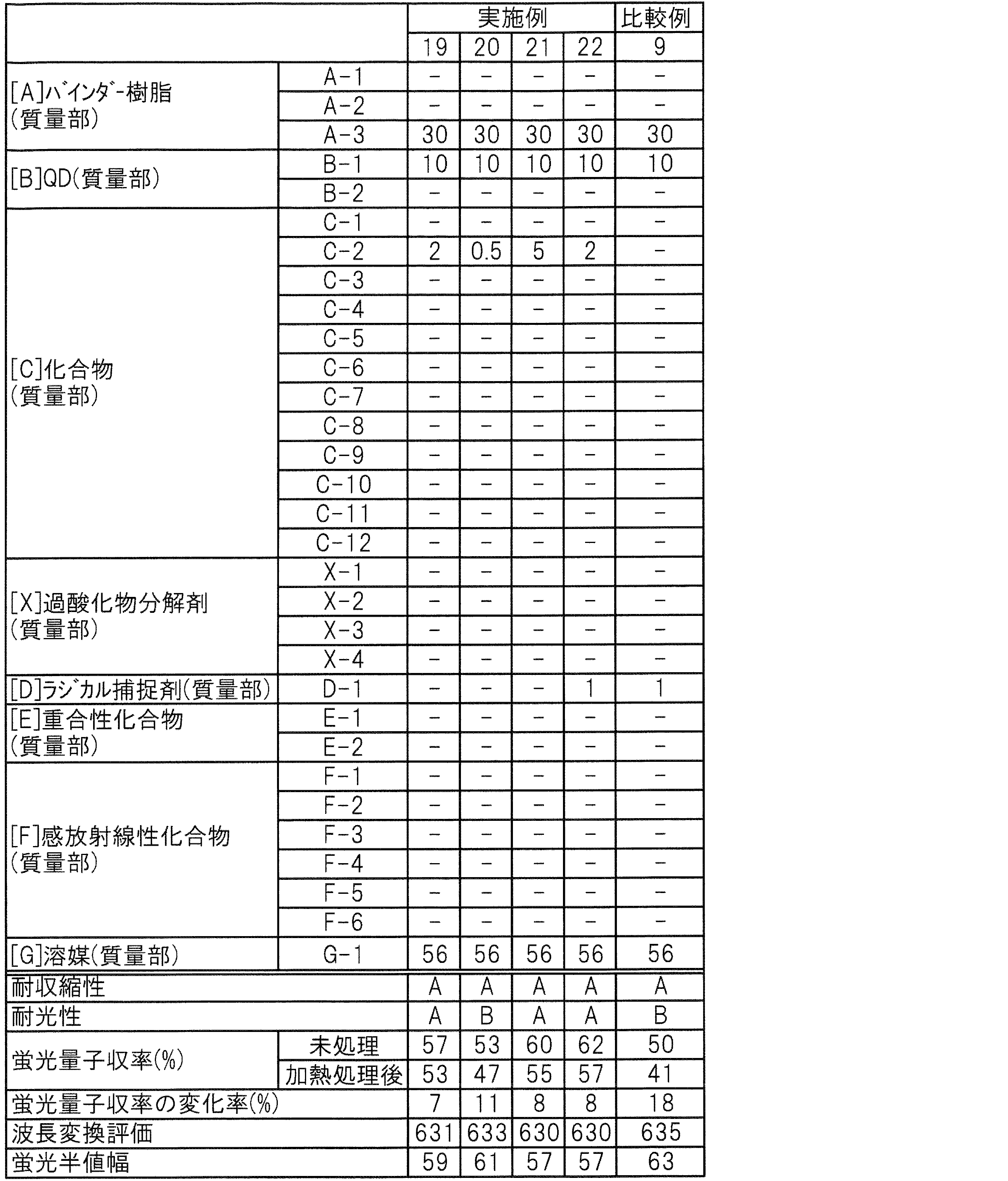
表2の結果から明らかなように、実施例19~22は、耐収縮性が良好であり、かつ比較例9と比べて蛍光量子収率及びその変化率、波長変換評価並びに蛍光半値幅の評価項目が良好であった。また、[A]バインダー樹脂100質量部に対する[C]化合物の含有量を2質量部以上とした実施例19、21及び22は、耐光性についても良好であった。
本発明によれば、加熱処理後のQDの蛍光量子収率の低下を抑制できる樹脂組成物、当該樹脂組成物により得られる膜、当該膜を用いた波長変換部材、及び当該樹脂組成物を用いた膜の形成方法を提供できる。
11 波長変換基板
12 第1基材
13 波長変換層
13a 第1波長変換層
13b 第2波長変換層
13c 第3波長変換層
14 ブラックマトリクス
15 接着剤層
16 第2基材
17 光源
17a 第1光源
17b 第2光源
17c 第3光源
18 光源基板
100 発光表示素子
12 第1基材
13 波長変換層
13a 第1波長変換層
13b 第2波長変換層
13c 第3波長変換層
14 ブラックマトリクス
15 接着剤層
16 第2基材
17 光源
17a 第1光源
17b 第2光源
17c 第3光源
18 光源基板
100 発光表示素子
Claims (15)
- バインダー樹脂、
半導体量子ドット、並びに
フェニルホスフィン構造を有する化合物、シクロアルキルホスフィン構造を有する化合物、チオビスフェノール構造を有する化合物、ジアルキルチオジプロピオネート構造を有する化合物及びベンゾチアゾール構造を有する化合物よりなる群から選ばれる少なくとも1種の化合物を含有する樹脂組成物。 - ラジカル捕捉剤をさらに含有する請求項1に記載の樹脂組成物。
- 重合性化合物をさらに含有する請求項1又は請求項2に記載の樹脂組成物。
- 上記バインダー樹脂が側鎖に脂環式構造を有する請求項1、請求項2又は請求項3に記載の樹脂組成物。
- 上記バインダー樹脂がアルカリ可溶性樹脂である請求項1から請求項4のいずれか1項に記載の樹脂組成物。
- 上記アルカリ可溶性樹脂が側鎖にカルボキシ基を有する請求項5に記載の樹脂組成物。
- 上記半導体量子ドットが、2族元素、11族元素、12族元素、13族元素、14族元素、15族元素及び16族元素よりなる群から選ばれる少なくとも2種の元素を含む請求項1から請求項6のいずれか1項に記載の樹脂組成物。
- 上記半導体量子ドットがInを含む請求項7に記載の樹脂組成物。
- 上記半導体量子ドットが、Inをコアの構成元素として含むコアシェル型構造を有する請求項8に記載の樹脂組成物。
- 上記半導体量子ドットがSiを含む請求項1から請求項6のいずれか1項に記載の樹脂組成物。
- 感放射線性化合物をさらに含有する請求項1から請求項10のいずれか1項に記載の樹脂組成物。
- 請求項1から請求項11のいずれか1項に記載の樹脂組成物により形成される膜。
- 請求項1から請求項11のいずれか1項に記載の樹脂組成物により形成される膜を備える波長変換部材。
- 基板の一方の面側に塗膜を形成する工程、及び
上記塗膜を加熱する工程
を備え、
上記塗膜を請求項1から請求項11のいずれか1項に記載の樹脂組成物により形成する膜の形成方法。 - 基板の一方の面側に塗膜を形成する工程、
上記塗膜の少なくとも一部に放射線を照射する工程、
放射線照射後の上記塗膜を現像する工程、及び
現像後の上記塗膜を加熱する工程
を備え、
上記塗膜を請求項11に記載の樹脂組成物により形成する膜の形成方法。
Priority Applications (1)
| Application Number | Priority Date | Filing Date | Title |
|---|---|---|---|
| KR1020177033673A KR20180035732A (ko) | 2015-07-29 | 2016-07-25 | 수지 조성물, 막, 파장 변환 부재 및 막의 형성 방법 |
Applications Claiming Priority (4)
| Application Number | Priority Date | Filing Date | Title |
|---|---|---|---|
| JP2015-149643 | 2015-07-29 | ||
| JP2015149643 | 2015-07-29 | ||
| JP2016142846A JP6834213B2 (ja) | 2015-07-29 | 2016-07-20 | 樹脂組成物、膜、波長変換部材、及び膜の形成方法 |
| JP2016-142846 | 2016-07-20 |
Publications (1)
| Publication Number | Publication Date |
|---|---|
| WO2017018392A1 true WO2017018392A1 (ja) | 2017-02-02 |
Family
ID=57884390
Family Applications (1)
| Application Number | Title | Priority Date | Filing Date |
|---|---|---|---|
| PCT/JP2016/071779 Ceased WO2017018392A1 (ja) | 2015-07-29 | 2016-07-25 | 樹脂組成物、膜、波長変換部材、及び膜の形成方法 |
Country Status (1)
| Country | Link |
|---|---|
| WO (1) | WO2017018392A1 (ja) |
Cited By (9)
| Publication number | Priority date | Publication date | Assignee | Title |
|---|---|---|---|---|
| JP2016108548A (ja) * | 2014-12-02 | 2016-06-20 | 東友ファインケム株式会社Dongwoo Fine−Chem Co., Ltd. | 自発光感光性樹脂組成物、これから製造されたカラーフィルタおよび前記カラーフィルタを含む画像表示装置 |
| WO2018180445A1 (ja) * | 2017-03-30 | 2018-10-04 | 住友化学株式会社 | 重合体及び組成物 |
| WO2019021813A1 (ja) * | 2017-07-28 | 2019-01-31 | 東レ株式会社 | 色変換組成物、色変換フィルムならびにそれを含む光源ユニット、ディスプレイおよび照明 |
| WO2019181698A1 (ja) * | 2018-03-23 | 2019-09-26 | 東レ株式会社 | 感光性樹脂組成物、硬化膜、色変換基板、画像表示装置、および硬化膜の製造方法 |
| JP2019532346A (ja) * | 2016-11-15 | 2019-11-07 | 東友ファインケム株式会社Dongwoo Fine−Chem Co., Ltd. | 感光性樹脂組成物、カラーフィルタ、及び画像表示装置 |
| WO2020217700A1 (ja) * | 2019-04-25 | 2020-10-29 | Jsr株式会社 | 感光性樹脂組成物 |
| JP2021089433A (ja) * | 2019-12-05 | 2021-06-10 | 東友ファインケム株式会社Dongwoo Fine−Chem Co., Ltd. | 白色感光性樹脂組成物、これを用いて製造されたカラーフィルターおよび画像表示装置 |
| JP2021149104A (ja) * | 2020-03-20 | 2021-09-27 | 東友ファインケム株式会社Dongwoo Fine−Chem Co., Ltd. | 白色感光性樹脂組成物、これを用いて製造されたカラーフィルタおよび画像表示装置 |
| TWI840326B (zh) * | 2017-02-15 | 2024-05-01 | 日商東京應化工業股份有限公司 | 間隔壁用圖案的形成方法 |
Citations (5)
| Publication number | Priority date | Publication date | Assignee | Title |
|---|---|---|---|---|
| JP2010277069A (ja) * | 2009-04-27 | 2010-12-09 | Jsr Corp | 感放射線性樹脂組成物、硬化膜及びその形成方法 |
| JP2015018131A (ja) * | 2013-07-11 | 2015-01-29 | Jsr株式会社 | 感放射線性樹脂組成物、硬化膜、発光素子、波長変換フィルムおよび発光層の形成方法 |
| JP2015121702A (ja) * | 2013-12-24 | 2015-07-02 | Jsr株式会社 | 硬化性樹脂組成物、硬化膜、発光素子、波長変換フィルムおよび発光層の形成方法 |
| WO2016035602A1 (ja) * | 2014-09-05 | 2016-03-10 | 住友化学株式会社 | 硬化性組成物 |
| JP2016108548A (ja) * | 2014-12-02 | 2016-06-20 | 東友ファインケム株式会社Dongwoo Fine−Chem Co., Ltd. | 自発光感光性樹脂組成物、これから製造されたカラーフィルタおよび前記カラーフィルタを含む画像表示装置 |
-
2016
- 2016-07-25 WO PCT/JP2016/071779 patent/WO2017018392A1/ja not_active Ceased
Patent Citations (5)
| Publication number | Priority date | Publication date | Assignee | Title |
|---|---|---|---|---|
| JP2010277069A (ja) * | 2009-04-27 | 2010-12-09 | Jsr Corp | 感放射線性樹脂組成物、硬化膜及びその形成方法 |
| JP2015018131A (ja) * | 2013-07-11 | 2015-01-29 | Jsr株式会社 | 感放射線性樹脂組成物、硬化膜、発光素子、波長変換フィルムおよび発光層の形成方法 |
| JP2015121702A (ja) * | 2013-12-24 | 2015-07-02 | Jsr株式会社 | 硬化性樹脂組成物、硬化膜、発光素子、波長変換フィルムおよび発光層の形成方法 |
| WO2016035602A1 (ja) * | 2014-09-05 | 2016-03-10 | 住友化学株式会社 | 硬化性組成物 |
| JP2016108548A (ja) * | 2014-12-02 | 2016-06-20 | 東友ファインケム株式会社Dongwoo Fine−Chem Co., Ltd. | 自発光感光性樹脂組成物、これから製造されたカラーフィルタおよび前記カラーフィルタを含む画像表示装置 |
Cited By (22)
| Publication number | Priority date | Publication date | Assignee | Title |
|---|---|---|---|---|
| JP2016108548A (ja) * | 2014-12-02 | 2016-06-20 | 東友ファインケム株式会社Dongwoo Fine−Chem Co., Ltd. | 自発光感光性樹脂組成物、これから製造されたカラーフィルタおよび前記カラーフィルタを含む画像表示装置 |
| JP2019532346A (ja) * | 2016-11-15 | 2019-11-07 | 東友ファインケム株式会社Dongwoo Fine−Chem Co., Ltd. | 感光性樹脂組成物、カラーフィルタ、及び画像表示装置 |
| TWI840326B (zh) * | 2017-02-15 | 2024-05-01 | 日商東京應化工業股份有限公司 | 間隔壁用圖案的形成方法 |
| WO2018180445A1 (ja) * | 2017-03-30 | 2018-10-04 | 住友化学株式会社 | 重合体及び組成物 |
| JP2018172637A (ja) * | 2017-03-30 | 2018-11-08 | 住友化学株式会社 | 重合体及び組成物 |
| KR20190127938A (ko) * | 2017-03-30 | 2019-11-13 | 스미또모 가가꾸 가부시키가이샤 | 중합체 및 조성물 |
| KR102461802B1 (ko) | 2017-03-30 | 2022-11-01 | 스미또모 가가꾸 가부시키가이샤 | 중합체 및 조성물 |
| CN110945389B (zh) * | 2017-07-28 | 2021-08-03 | 东丽株式会社 | 颜色转换组合物、颜色转换膜以及包含其的装置 |
| WO2019021813A1 (ja) * | 2017-07-28 | 2019-01-31 | 東レ株式会社 | 色変換組成物、色変換フィルムならびにそれを含む光源ユニット、ディスプレイおよび照明 |
| JPWO2019021813A1 (ja) * | 2017-07-28 | 2019-07-25 | 東レ株式会社 | 色変換組成物、色変換フィルムならびにそれを含む光源ユニット、ディスプレイおよび照明 |
| CN110945389A (zh) * | 2017-07-28 | 2020-03-31 | 东丽株式会社 | 颜色转换组合物、颜色转换膜以及包含其的光源单元、显示器及照明 |
| US11459504B2 (en) | 2017-07-28 | 2022-10-04 | Toray Industries, Inc. | Color conversion composition and color conversion film, and light source unit, display, and lighting including same |
| WO2019181698A1 (ja) * | 2018-03-23 | 2019-09-26 | 東レ株式会社 | 感光性樹脂組成物、硬化膜、色変換基板、画像表示装置、および硬化膜の製造方法 |
| JPWO2019181698A1 (ja) * | 2018-03-23 | 2021-02-04 | 東レ株式会社 | 感光性樹脂組成物、硬化膜、色変換基板、画像表示装置、および硬化膜の製造方法 |
| KR20200135942A (ko) * | 2018-03-23 | 2020-12-04 | 도레이 카부시키가이샤 | 감광성 수지 조성물, 경화막, 색변환 기판, 화상 표시 장치, 및 경화막의 제조 방법 |
| JP7259741B2 (ja) | 2018-03-23 | 2023-04-18 | 東レ株式会社 | 感光性樹脂組成物、硬化膜、色変換基板、画像表示装置、および硬化膜の製造方法 |
| KR102599290B1 (ko) | 2018-03-23 | 2023-11-07 | 도레이 카부시키가이샤 | 감광성 수지 조성물, 경화막, 색변환 기판, 화상 표시 장치, 및 경화막의 제조 방법 |
| WO2020217700A1 (ja) * | 2019-04-25 | 2020-10-29 | Jsr株式会社 | 感光性樹脂組成物 |
| JP2021089433A (ja) * | 2019-12-05 | 2021-06-10 | 東友ファインケム株式会社Dongwoo Fine−Chem Co., Ltd. | 白色感光性樹脂組成物、これを用いて製造されたカラーフィルターおよび画像表示装置 |
| JP7591391B2 (ja) | 2019-12-05 | 2024-11-28 | 東友ファインケム株式会社 | 白色感光性樹脂組成物、これを用いて製造されたカラーフィルターおよび画像表示装置 |
| JP2021149104A (ja) * | 2020-03-20 | 2021-09-27 | 東友ファインケム株式会社Dongwoo Fine−Chem Co., Ltd. | 白色感光性樹脂組成物、これを用いて製造されたカラーフィルタおよび画像表示装置 |
| JP7500478B2 (ja) | 2020-03-20 | 2024-06-17 | 東友ファインケム株式会社 | 白色感光性樹脂組成物、これを用いて製造されたカラーフィルタおよび画像表示装置 |
Similar Documents
| Publication | Publication Date | Title |
|---|---|---|
| JP6834213B2 (ja) | 樹脂組成物、膜、波長変換部材、及び膜の形成方法 | |
| WO2017018392A1 (ja) | 樹脂組成物、膜、波長変換部材、及び膜の形成方法 | |
| KR102325621B1 (ko) | 경화성 수지 조성물, 경화막, 파장 변환 필름, 발광층의 형성 방법 및 발광 표시 소자 | |
| KR102276034B1 (ko) | 경화성 수지 조성물, 경화막, 발광 소자, 파장 변환 필름 및 발광층의 형성 방법 | |
| KR102883855B1 (ko) | 경화성 수지 조성물, 경화막 및 표시 장치 | |
| JP6497251B2 (ja) | 硬化膜形成用組成物、硬化膜、発光表示素子、硬化膜の形成方法及び分散液 | |
| JP6171923B2 (ja) | 硬化性樹脂組成物、硬化膜、発光素子、波長変換フィルムおよび発光層の形成方法 | |
| JP6427876B2 (ja) | 感放射線性樹脂組成物、硬化膜、発光素子および発光層の形成方法 | |
| JP2021170137A (ja) | 量子ドット含有組成物、量子ドット製造方法およびカラーフィルタ | |
| JP2017032918A (ja) | 硬化膜形成用組成物、硬化膜、発光表示素子、フィルム及び硬化膜の形成方法 | |
| JPWO2016098570A1 (ja) | 有機el素子、硬化性樹脂組成物、波長変換部の形成方法および有機el装置 | |
| TW201835113A (zh) | 硬化性樹脂組成物、硬化膜及顯示裝置 | |
| CN112724959A (zh) | 量子点、包括其的可固化组合物、固化层以及彩色滤光器 | |
| JP2014174406A (ja) | 感放射線性樹脂組成物、硬化膜、発光表示素子および発光層の形成方法 | |
| CN108445716B (zh) | 固化性树脂组合物、固化膜及显示装置 | |
| JP6657684B2 (ja) | 硬化膜形成用組成物、硬化膜、発光表示素子及び硬化膜の形成方法 | |
| KR102197936B1 (ko) | 경화성 수지 조성물, 경화막, 발광 소자, 파장 변환 필름 및 발광층의 형성 방법 | |
| KR102195513B1 (ko) | 경화성 수지 조성물, 경화막, 발광 소자 및 발광층의 형성 방법 | |
| KR102749148B1 (ko) | 착색 감광성 수지 조성물, 이를 이용하여 제조된 컬러필터 및 표시장치 | |
| TW202535986A (zh) | 可固化組成物、使用該組成物的固化層、包括固化層的彩色濾光片、及包括彩色濾光片的顯示裝置 | |
| TW202502944A (zh) | 可固化組成物、使用所述組成物的固化層及包括所述固化層的顯示裝置 | |
| TW202511302A (zh) | 可固化組成物、使用所述組成物的固化層及包括所述固化層的顯示裝置 | |
| TW202449116A (zh) | 可固化組合物、使用所述組合物的固化層以及包括所述固化層的顯示裝置 | |
| CN119105237A (zh) | 感放射线性组合物、硬化物、显示装置、摄像装置及硬化物的制造方法 |
Legal Events
| Date | Code | Title | Description |
|---|---|---|---|
| 121 | Ep: the epo has been informed by wipo that ep was designated in this application |
Ref document number: 16830497 Country of ref document: EP Kind code of ref document: A1 |
|
| ENP | Entry into the national phase |
Ref document number: 20177033673 Country of ref document: KR Kind code of ref document: A |
|
| NENP | Non-entry into the national phase |
Ref country code: DE |
|
| 122 | Ep: pct application non-entry in european phase |
Ref document number: 16830497 Country of ref document: EP Kind code of ref document: A1 |