WO2017018286A1 - 表面処理鋼板およびその製造方法、並びにこの表面処理鋼板を用いた容器 - Google Patents
表面処理鋼板およびその製造方法、並びにこの表面処理鋼板を用いた容器 Download PDFInfo
- Publication number
- WO2017018286A1 WO2017018286A1 PCT/JP2016/071222 JP2016071222W WO2017018286A1 WO 2017018286 A1 WO2017018286 A1 WO 2017018286A1 JP 2016071222 W JP2016071222 W JP 2016071222W WO 2017018286 A1 WO2017018286 A1 WO 2017018286A1
- Authority
- WO
- WIPO (PCT)
- Prior art keywords
- plating
- layer
- steel sheet
- plating layer
- coating
- Prior art date
- Legal status (The legal status is an assumption and is not a legal conclusion. Google has not performed a legal analysis and makes no representation as to the accuracy of the status listed.)
- Ceased
Links
Images





Classifications
-
- C—CHEMISTRY; METALLURGY
- C23—COATING METALLIC MATERIAL; COATING MATERIAL WITH METALLIC MATERIAL; CHEMICAL SURFACE TREATMENT; DIFFUSION TREATMENT OF METALLIC MATERIAL; COATING BY VACUUM EVAPORATION, BY SPUTTERING, BY ION IMPLANTATION OR BY CHEMICAL VAPOUR DEPOSITION, IN GENERAL; INHIBITING CORROSION OF METALLIC MATERIAL OR INCRUSTATION IN GENERAL
- C23C—COATING METALLIC MATERIAL; COATING MATERIAL WITH METALLIC MATERIAL; SURFACE TREATMENT OF METALLIC MATERIAL BY DIFFUSION INTO THE SURFACE, BY CHEMICAL CONVERSION OR SUBSTITUTION; COATING BY VACUUM EVAPORATION, BY SPUTTERING, BY ION IMPLANTATION OR BY CHEMICAL VAPOUR DEPOSITION, IN GENERAL
- C23C28/00—Coating for obtaining at least two superposed coatings either by methods not provided for in a single one of groups C23C2/00 - C23C26/00 or by combinations of methods provided for in subclasses C23C and C25C or C25D
-
- C—CHEMISTRY; METALLURGY
- C25—ELECTROLYTIC OR ELECTROPHORETIC PROCESSES; APPARATUS THEREFOR
- C25D—PROCESSES FOR THE ELECTROLYTIC OR ELECTROPHORETIC PRODUCTION OF COATINGS; ELECTROFORMING; APPARATUS THEREFOR
- C25D5/00—Electroplating characterised by the process; Pretreatment or after-treatment of workpieces
- C25D5/60—Electroplating characterised by the structure or texture of the layers
- C25D5/615—Microstructure of the layers, e.g. mixed structure
- C25D5/617—Crystalline layers
-
- C—CHEMISTRY; METALLURGY
- C25—ELECTROLYTIC OR ELECTROPHORETIC PROCESSES; APPARATUS THEREFOR
- C25D—PROCESSES FOR THE ELECTROLYTIC OR ELECTROPHORETIC PRODUCTION OF COATINGS; ELECTROFORMING; APPARATUS THEREFOR
- C25D5/00—Electroplating characterised by the process; Pretreatment or after-treatment of workpieces
- C25D5/48—After-treatment of electroplated surfaces
-
- C—CHEMISTRY; METALLURGY
- C25—ELECTROLYTIC OR ELECTROPHORETIC PROCESSES; APPARATUS THEREFOR
- C25D—PROCESSES FOR THE ELECTROLYTIC OR ELECTROPHORETIC PRODUCTION OF COATINGS; ELECTROFORMING; APPARATUS THEREFOR
- C25D5/00—Electroplating characterised by the process; Pretreatment or after-treatment of workpieces
- C25D5/60—Electroplating characterised by the structure or texture of the layers
- C25D5/605—Surface topography of the layers, e.g. rough, dendritic or nodular layers
-
- C—CHEMISTRY; METALLURGY
- C25—ELECTROLYTIC OR ELECTROPHORETIC PROCESSES; APPARATUS THEREFOR
- C25D—PROCESSES FOR THE ELECTROLYTIC OR ELECTROPHORETIC PRODUCTION OF COATINGS; ELECTROFORMING; APPARATUS THEREFOR
- C25D9/00—Electrolytic coating other than with metals
- C25D9/04—Electrolytic coating other than with metals with inorganic materials
- C25D9/08—Electrolytic coating other than with metals with inorganic materials by cathodic processes
-
- C—CHEMISTRY; METALLURGY
- C25—ELECTROLYTIC OR ELECTROPHORETIC PROCESSES; APPARATUS THEREFOR
- C25D—PROCESSES FOR THE ELECTROLYTIC OR ELECTROPHORETIC PRODUCTION OF COATINGS; ELECTROFORMING; APPARATUS THEREFOR
- C25D5/00—Electroplating characterised by the process; Pretreatment or after-treatment of workpieces
- C25D5/10—Electroplating with more than one layer of the same or of different metals
- C25D5/12—Electroplating with more than one layer of the same or of different metals at least one layer being of nickel or chromium
Definitions
- the present invention relates to a surface-treated steel sheet obtained by coating a nickel-plated steel sheet with an organic resin layer, and in particular, an organic resin-coated steel sheet having excellent adhesion of the organic resin layer after processing when processed, a method for producing the same, and the organic
- the present invention relates to a container such as a metal can using a resin-coated steel plate.
- a transition is progressing from a conventional three-piece type consisting of a can body, a canopy, and a bottom cover to a seamless can in which the can body and the bottom are integrated.
- This seamless can has a feature that it can contribute to resource saving by reducing the thickness of the can body.
- adhesiveness with coating resin formed on a steel plate is required.
- Patent Document 1 a surface-treated steel sheet in which tin plating is performed after non-uniform island-like nickel plating has been proposed. Furthermore, in order to overcome the problem that the conventional nickel-plated steel sheet does not have sufficient adhesion to the organic coating resin layer, the organic coating resin and the organic coating resin are formed by forming concavo-convex fine particles made of nickel with a dilute nickel plating bath. A technique for realizing a surface-treated steel sheet having excellent processing adhesion is also known (see, for example, Patent Document 2).
- the present invention has been made in view of solving such problems, and does not increase the amount of Ni plating excessively, and yet maintains the adhesion to the coating resin, the organic resin-coated steel sheet, and these It aims at providing the container using the manufacturing method and this organic resin coated steel plate.
- a surface-treated steel sheet includes a base material, a granular Ni plating layer formed on the base material, and an Sn plating formed on the Ni plating layer.
- the Ni plating layer has a Ni particle density of 500 to 1000 particles / ⁇ m 2 , the Ni average particle diameter is 0.01 to 0.05 ⁇ m, and the Ni plating layer has a plating amount of 0.01 to 1.0 g / m 2 , and the amount of plating in the Sn plating layer is 0.4 to 2.0 g / m 2 .
- the surface-treated steel sheet having the feature (1) described above (2) a Ni—Fe alloy layer, a Ni—Sn alloy layer, and a Ni—Sn are formed at the interface between the Ni plating layer and the Sn plating layer. It is preferable that at least one of the -Fe alloy layers is interposed. Further, in the surface-treated steel sheet having the above feature (2), (3) from the base material side, the Ni—Fe alloy layer, the granular Ni plating layer, the Ni—Sn—Fe alloy layer, It is preferable that the Ni—Sn layer and the Sn plating layer are laminated in this order. In the surface-treated steel sheet having the feature (1) described above, (4) the Ni plating layer is made of at least one of a Ni—Sn alloy, a Ni—Sn—Fe alloy, and a Ni—Fe alloy. preferable.
- an organic resin-coated steel sheet according to one embodiment of the present invention has an organic resin layer coated on the surface-treated steel sheet according to any one of (1) to (6). It is characterized by.
- the container concerning one Embodiment of this invention consists of an above described organic resin coating steel plate. Examples of the container include a metal can, a lid, or a metal case that stores beverages, food, medicines, and the like.
- a method for manufacturing a surface-treated steel sheet according to an embodiment of the present invention includes performing Ni plating on a base material with a plating amount of 0.01 to 1.0 g / m 2. Forming a granular Ni plating layer in which the Ni particle density in the Ni plating is 500 to 1000 particles / ⁇ m 2 and the average particle diameter of the Ni is 0.01 to 0.05 ⁇ m; Forming a Sn plating layer on the granular Ni layer by performing Sn plating on the base material on which the Ni layer is formed.
- the granular Ni plating layer and the Sn plating layer are formed in an optimal state and ratio, a surface-treated steel sheet having excellent adhesion to the coating resin at the side wall of the can and excellent in corrosion resistance can be obtained. Can be realized.
- the surface-treated steel sheet according to the present embodiment includes at least a base material and a surface treatment layer formed on the base material.
- the surface treatment layer includes at least a granular Ni plating layer and an Sn plating layer formed on the granular Ni plating layer.
- ⁇ Base material> As the base material of the surface-treated steel sheet, metal plates such as iron and various alloys of about 0.1 mm to 0.5 mm are used. Examples of the metal plate include steel plates that have been subjected to various surface treatments such as tinplate, TFS, and nickel-plated steel plates, but cold-rolled steel plates are preferable.
- a particularly suitable steel sheet for example, a low carbon aluminum killed steel having a carbon content of 0.01% by mass to 0.15% by mass generally used for cans can be used. Furthermore, non-aging ultra-low carbon aluminum killed steel having a carbon content of less than 0.01% by mass with addition of niobium or titanium is also applicable. These aluminum killed steel hot-rolled sheets are pickled with electrolytic pickling, etc. to remove surface scales, then cold-rolled, and then subjected to electrolytic cleaning, annealing, rolling, etc. It may be used as
- the surface treatment layer of the present embodiment is formed on at least one surface side of the substrate, and includes a granular Ni plating layer and an Sn plating layer formed above the Ni plating layer.
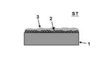
- FIG. 1 is a cross-sectional view schematically showing the structure of the surface-treated steel sheet ST according to this embodiment, and more specifically, the above-described base material 1 and the surface treatment layer are schematically shown. .
- the surface treatment layer includes the granular Ni plating layer 2 and the Sn plating layer 3.
- the granular Ni plating layer 2 has a granular appearance on the substrate 1.
- “granular” means a state having the following characteristic values at the same time.
- the particle density of the granular Ni plating layer 2 in this embodiment is 500 / ⁇ m 2 to 1000 / ⁇ m 2 .
- the particle density is less than 500 particles / ⁇ m 2 , the nickel particles are too fine, the plating surface shape becomes too flat, and sufficient adhesion cannot be obtained.
- the particle density exceeds 1000 particles / ⁇ m 2 , the plating surface shape becomes too smooth and sufficient adhesion cannot be obtained.
- this granular Ni plating layer 2 and Sn plating layer 3 can be combined to produce an effect of excellent adhesion and corrosion resistance, but it is desirable to further perform heat treatment.
- an effect of further excellent adhesion can be produced. That is, a Ni—Sn layer or a Ni—Sn—Fe alloy layer is formed by this heat treatment, and these can produce an anchor effect at the side wall of the can, thereby obtaining sufficient adhesion.
- adhesion due to the anchor effect can be obtained even when the Ni plating layer is made of at least one of a Ni—Sn alloy, a Ni—Sn—Fe alloy, and a Ni—Fe alloy. (Details will be described later).
- the “particle density” is a range of 1 ⁇ 1 ⁇ m (that is, 1 ⁇ m 2 ) when the surface of the surface treatment film 2 is observed with a scanning electron microscope (SEM) and the average particle diameter of the particles is approximately 0.5 ⁇ m or less. Is obtained by measuring the number of nickel particles per unit area by counting the number of particles present in the range. In this case, 1 particle was completely included in the 1 ⁇ 1 ⁇ m frame, and 0.5 particles were counted for only a part of the particles contained in the frame. And this operation is performed about five places on the surface of a nickel plating layer, and particle density can be calculated
- the second characteristic value examples include a value of particle diameter (average particle diameter). That is, the average particle diameter of the granular Ni plating layer 2 in this embodiment is 0.01 ⁇ m to 0.05 ⁇ m. If this average particle diameter is less than 0.01 ⁇ m, the nickel plating becomes too fine and smooth, and sufficient adhesion cannot be obtained. On the other hand, if it exceeds 0.05 ⁇ m, the plating surface shape becomes too smooth, and sufficient adhesion cannot be obtained.
- the average particle diameter is calculated by calculating the average occupied area per particle from the particle density per unit area of 1 ⁇ 1 ⁇ m obtained by observing the surface of the surface treatment film 2 with a scanning electron microscope (SEM). The diameter of a circle corresponding to the average occupied area can be calculated and obtained.
- the Sn plating layer 3 formed on the granular Ni plating layer 2 will be described.
- the Sn plating layer 3 is formed on the granular Ni plating layer 2 so as to cover the granular Ni plating layer 2.
- the surface of the Sn plating layer 3 is not smooth following the granular Ni plating layer 2. It is in a state where a rough undulation is formed.
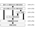
- the above-described granular Ni plating layer 2 is formed on the base material 1 by plating (step 1).
- the plating process is performed so that the Ni plating amount is 0.01 g / m 2 to 1.0 g / m 2 .
- the Ni plating amount is less than 0.01 g / m 2 , the deposited Ni plating amount is not sufficient, and sufficient adhesion cannot be ensured.
- the Ni plating amount exceeds 1.0 g / m 2 , the adhesion due to the expression of the anchor effect is sufficient, but it is not preferable because the cost increases.
- the Sn plating layer 3 is formed on the Ni plating layer 2 described above (step 2).
- the plating process is performed so that the Sn plating amount is 0.4 g / m 2 to 2.0 g / m 2 .
- the Sn plating amount is less than 0.4 g / m 2 , a sufficient Ni—Sn alloy layer or Ni—Sn—Fe alloy layer is not formed during heat treatment, and sufficient adhesion cannot be obtained, and the corrosion resistance is not improved.
- the Sn plating amount exceeds 2.0 g / m 2 , the surface of the film becomes flat, so the anchor effect is small and sufficient adhesion cannot be obtained.
- the Sn plating amount is more preferably 0.4 g / m 2 to 0.7 g / m 2 .
- step 3 a reflow process (melt heat treatment) is performed on the substrate 1 on which the Ni plating layer 2 and the Sn plating layer 3 are formed (step 3).
- a reflow process (melt heat treatment) is performed on the substrate 1 on which the Ni plating layer 2 and the Sn plating layer 3 are formed (step 3).
- a reflow treatment as shown in FIG. 3, near the interface between the Ni plating layer 2 and the Sn plating layer 3, a Ni—Sn alloy layer, a Ni—Fe alloy layer or a Ni—Sn—Fe alloy layer (Referred to as an alloy layer AL), whereby the surface treatment layer of this embodiment is formed on the substrate 1.
- step 3 reflow processing
- step 3 reflow processing
- the alloy layer AL is uniformly formed on the Ni plating layer 2 of the substrate 1, but is not particularly limited to this aspect.
- the alloy layer AL may be partially formed on the Ni plating layer 2 or may be formed so that at least a part of the alloy layer AL is in contact with the substrate 1.
- the heat treatment at the time of the reflow treatment is not particularly limited as long as the heating temperature or the heating time is a condition that the alloying of Ni and Sn proceeds and the above-described alloy layer is formed. It is preferable that the heating temperature is 180 to 240 ° C. and the heating time is 0.1 to 8 seconds. Further, even when the reflow treatment is not performed, it is sufficient to perform at 220 ° C.
- step 3 (melting heat treatment) after forming the Sn plating layer 3 is not essential, and the above-described alloy layer AL may be formed by heat treatment when the organic resin layer is laminated. Therefore, when manufacturing the organic resin-coated steel sheet of the present embodiment described later, a Ni—Sn alloy layer, a Ni—Fe alloy layer, or a Ni—Sn—Fe alloy layer is present. Therefore, the presence of these alloy layers is not always essential. However, from the viewpoint of suppressing the generation of smudge (tin powder) in the plating line and the laminating process, it can be said that it is preferable to perform Step 3 (melting heat treatment).
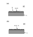
- the Ni plating layer may be formed of a Ni—Sn alloy, a Ni—Sn—Fe alloy, or a Ni—Fe alloy (the entire Ni plating layer may be alloyed).
- the Ni plating layer 2 becomes the alloy layer AL, and the Sn plating layer 3 is coated on the alloy layer AL.
- alloying may occur until the Sn plating layer 3 does not remain on the alloy layer AL.
- a coating layer 4 or an organic resin layer 5 described later is coated. That is, in FIG.
- the Sn plating layer 3 is alloyed and changed to the alloy layer AL, but such a form is also included in the surface treatment layer of the present invention.
- the surface-treated steel sheet ST of the present embodiment is manufactured.
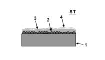
- the coating layer 4 as a film of at least one oxide of Ti and Al (for example, ZrO 2 , TiO 2 , Al 2 O 3, etc.) may be formed. That is, in the present embodiment, the step of forming the coating layer 4 is not essential, but it is more preferable if the coating layer 4 is on the surface treatment layer.
- step 4 formation of the coating layer 4
- step 4 formation of coating layer 4
- step 4 formation of coating layer 4
- step 4 formation of coating layer 4
- step 4 formation of coating layer 4
- step 4 formation of coating layer 4
- step 4 omitted
- step 2 to step 5 it is possible to move from step 2 to step 5 or from step 3 to step 5.
- the coating layer 4 of this embodiment may contain not only the above oxide but also a hydroxide. Therefore, the “oxide” in the present embodiment is used as a concept that may contain a hydroxide at least in part.
- the formation of the coating layer 4 is not limited to the above.
- a film in a form using a passivating action such as molybdic acid (including a form to which a predetermined ratio of phosphoric acid is added) or tungstic acid
- Reactive coatings based on fluorides, phosphates, nitrates and sulfates of transition metals such as Ti, Zr, V, Mn, Ni and Co, and polypinylphenol derivatives and polyacrylic acid Coated coating type coatings (3) reactive type coatings based on chlorides and nitrates of rare elements such as Y, La, and Ce, or oxyacid salts such as molybdic acid and tungstic acid
- Films based on polyphenolic carboxylic acids such as tannic acid and chelating agents such as thiourea containing sulfur and nitrogen.
- Various forms of coating may be used.
- the coating layer 4 may contain an oxide of phosphorus in addition to the above oxide.
- a phosphate compound layer made of Fe or Sn may be formed, or may be formed in the form of a phosphate compound such as Zr phosphate or Al phosphate.
- phosphoric acid By containing phosphoric acid, adhesion with the organic resin layer can be improved and plating defects such as pinholes can be reduced.
- the coating amount of the coating layer 4, Zr oxide, Al oxide, both 1 ⁇ 30mg / m 2 of Ti oxides, oxides of phosphorus is preferably 0.1 ⁇ 5mg / m 2.
- the oxide of phosphorus when a coating layer mainly composed of oxides of P (phosphorus) and Al (aluminum) is formed, the Al coating amount is preferably 1 to 15 mg / m 2 .
- the preferable coating amount of P with respect to Al is 0.5 to 3 mg / m 2 .
- the organic resin layer 5 may be formed on the surface-treated steel plate ST described above. More specifically, after the above-described surface-treated steel plate ST is manufactured, or when the above-described coating layer 4 is formed, after the formation of the coating layer 4, an organic resin layer 5 is formed thereon to form an organic layer. A resin-coated steel sheet RT is manufactured. Although the description of the alloy layer AL is omitted in FIG. 6, the alloy layer AL described above may be formed in the vicinity of the interface between the Ni plating layer 2 and the Sn plating layer 3 as in the case of FIG. As in the case of FIG.
- the Ni plating layer 2 and the Sn plating layer 3 may be completely alloyed to form the alloy layer AL.
- Various known paints can be applied to the organic resin layer 5, and examples thereof include polyester resins, epoxy phenol resins, and polyvinyl chloride resins.
- polyester resins are preferred because they are easy to paint and bake, have excellent workability, adhesion to metals, and retort resistance, and do not generate toxic or corrosive gases during incineration.
- polyester resins include ethylene terephthalate, butylene terephthalate, 1,4-cyclohexanedimethyl terephthalate, ethylene isophthalate, butylene isophthalate, ethylene adipate, butylene adipate, ethylene naphthalate, and butylene naphthalate.
- polyester resins containing the above esters include polyester resins containing the above esters.
- the organic resin layer 5 of the present embodiment may be a multilayer film composed of a plurality of layers, and may preferably be composed of two or three layers.
- FIG. 7 shows a seamless can using the surface-treated steel sheet ST and the organic resin-coated steel sheet RT of the present embodiment.
- FIG. 7 shows an example in which the surface treatment layer, the coating layer 4 and the organic resin layer 5 described above are coated on the inner surface side of the seamless can.
- the film surface treatment layer, coating layer 4, organic resin layer 5, etc.
- the film of this embodiment may be formed on both the inner and outer surfaces of the seamless can, and other known films may be formed on the other surface side.
- Example 1 A cold rolled steel sheet of low carbon aluminum killed steel having a thickness of 0.225 mm was used as a base material.
- this base material was electrolytically degreased in an aqueous alkaline solution and washed with water, and further washed with sulfuric acid and washed with water, and then formed into a concavo-convex shape with a nickel plating film amount of 0.02 g / m 2 in a nickel plating bath. A granular Ni plating layer was formed.
- the Sn plating layer was formed by setting the amount of Sn plating to 0.7 g / m 2 in a tin plating bath.
- the particle density in the Ni plating layer was 800 particles / ⁇ m 2 and the average particle size was 0.03 ⁇ m.
- the surface-treated steel sheet ST obtained under the above conditions is subjected to reflow treatment (heating treatment), and the above alloy layers (Ni—Sn alloy layer, Ni—Fe alloy layer and Ni—Sn—Fe alloy layer) are formed. Formed.
- the types of alloy layers to be formed need not be all of the Ni—Sn alloy layer, the Ni—Fe alloy layer, and the Ni—Sn—Fe alloy layer, and an aspect in which at least one of them is formed. But you can.
- the melt heat treatment was performed for 5.6 seconds at a temperature of 240 ° C. higher than the melting point of Sn.
- the heating temperature can be appropriately selected as long as it is within the melting point of tin or higher, and the heating time can be appropriately selected as long as it is within the range of 0.1 second to 8 seconds. .
- the heating temperature or heating time is not particularly limited as long as the alloying of Ni and Sn proceeds and the above-described alloy layer is formed.
- the specific plating bath conditions were as follows. ⁇ Nickel plating bath and plating conditions> Nickel sulfate 40g / L Ammonium sulfate 20g / L Citric acid 15g / L pH 4.0 Bath temperature 45 ° C Current density 50A / dm 2 The amount of nickel sulfate may be adjusted as appropriate as long as it is 40 to 60 g / L. The amount of ammonium sulfate may be adjusted as appropriate as long as it is 20 to 100 g / L.
- ⁇ Tin plating bath and plating conditions Stannous sulfate 80g / L Phenolsulfonic acid 60g / L Additive A (Ethoxylated- ⁇ -naphthol) 3g / L Additive B (Ethoxynaphtholsulfonic acid) 3g / L pH 1 or less Bath temperature 40 ° C Current density 10A / dm 2 The amount of stannous sulfate may be adjusted as appropriate as long as it is 10 to 200 g / L. Further, the amount of phenolsulfonic acid sulfuric acid may be appropriately adjusted as long as it is 5 to 100 g / L.
- a coating layer (coating amount 5.0 mg / m 2 ) mainly composed of an oxide of Zr (zirconium) was formed on the surface-treated steel sheet. Then, the surface-treated steel sheet on which the coating layer was formed was heat-treated at a temperature of 220 ° C. for 30 seconds, and a polyethylene terephthalate unstretched film (thickness 20 ⁇ m) in which 12 mol% of isophthalic acid was modified on both surfaces was heat-laminated.
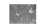
- FIG. 8A shows an SEM image relating to the surface morphology after Ni plating in Example 1
- FIG. 8B shows an SEM image relating to the surface morphology after undergoing Sn plating and reflow treatment.
- This SEM image was obtained by observing the surface under the conditions of an acceleration voltage of 5 kV and a current of 12 ⁇ A using a scanning electron microscope (manufactured by Hitachi High-Technologies Corporation, SU8020), and performing imaging.
- Example 2 The same procedure as in Example 1 was performed, except that the temperature in the reflow treatment was 210 ° C. and the coating amount of the coating layer mainly composed of Zr oxide was 9.3 mg / m 2 .
- Example 3 In the formation of the Ni plating layer, the coating amount of Ni plating is 0.1 g / m 2 , the particle density is 504 particles / ⁇ m 2 , the average particle size is 0.05 ⁇ m, and the main component is Zr oxide. The same operation as in Example 1 was performed except that the coating amount of the layer was 6.4 mg / m 2 .
- the SEM image regarding the surface form after Ni plating in Example 3 is shown in FIG.
- Example 4 In the formation of the Ni plating layer, the coating amount of Ni plating is 0.1 g / m 2 , the particle density is 504 particles / ⁇ m 2 , the average particle size is 0.05 ⁇ m, the temperature in reflow treatment is 210 ° C., and Zr This was carried out in the same manner as in Example 1 except that the coating amount of the coating layer containing as a main component the oxide was 7.3 mg / m 2 .
- Example 5 In forming the Ni plating layer, the coating amount of Ni plating was 0.5 g / m 2 , the particle density was 610 particles / ⁇ m 2 , and the average particle size was 0.05 ⁇ m. Further, in the formation of the Sn plating layer, the coating amount of Sn plating was 1.4 g / m 2, and the coating amount of the coating layer mainly composed of Zr oxide was 8.0 mg / m 2 . Except for the above, the same procedure as in Example 1 was performed.
- the coating amount of Ni plating was 0.5 g / m 2 , the particle density was 610 particles / ⁇ m 2 , and the average particle size was 0.05 ⁇ m. Further, in the formation of the Sn plating layer, the coating amount of the Sn plating is 1.5 g / m 2 and the reflow treatment is not performed, and the coating amount of the coating layer mainly composed of Zr oxide is 5.1 mg / m 2. It was. Except for the above, the same procedure as in Example 1 was performed.
- Example 7 In forming the Ni plating layer, the coating amount of Ni plating was 0.5 g / m 2 , the particle density was 610 particles / ⁇ m 2 , and the average particle size was 0.05 ⁇ m. Further, in the formation of the Sn plating layer, the coating amount of the Sn plating is 1.5 g / m 2 , the temperature in the reflow treatment is 210 ° C., and the coating amount of the coating layer mainly composed of Zr oxide is 5. It was 9 mg / m 2 . Except for the above, the same procedure as in Example 1 was performed.
- the coating amount of Ni plating was 0.5 g / m 2
- the particle density was 610 particles / ⁇ m 2
- the average particle size was 0.05 ⁇ m.
- the film amount of Sn plating was 0.7 g / m ⁇ 2 >, and the reflow process was not performed.
- the surface-treated steel sheet ST manufactured through the above steps was subjected to cathodic electrolysis in a pH 3.0 treatment bath containing aluminum nitrate as a main component, and then washed with water and dried.
- Example 2 instead of the coating layer mainly composed of the oxide of Zr in Example 1, a coating layer mainly composed of an oxide of Al (aluminum) was formed on the surface-treated steel sheet ST, and the coating amount was It was set to 7.7 mg / m 2 . Except for the above, the same procedure as in Example 1 was performed.
- Example 9 In forming the Ni plating layer, the coating amount of Ni plating was 0.5 g / m 2 , the particle density was 610 particles / ⁇ m 2 , and the average particle size was 0.05 ⁇ m. Further, in the formation of the Sn plating layer, the coating amount of the Sn plating layer is 0.7 g / m 2 , the temperature in the reflow process is 210 ° C., and the coating amount of the coating layer mainly composed of an oxide of Al (aluminum). Was 9.3 mg / m 2 . Except for the above, the same procedure as in Example 1 was performed.
- the coating amount of Ni plating was 0.5 g / m 2 , the particle density was 610 particles / ⁇ m 2 , and the average particle size was 0.05 ⁇ m. Further, in the formation of the Sn plating layer, the coating amount of Sn plating is set to 0.4 g / m 2 , the reflow treatment is not performed, and the coating amount of the coating layer mainly composed of an oxide of Al (aluminum) is set to 9. It was 9 mg / m 2 . Except for the above, the same procedure as in Example 1 was performed.
- the coating amount of Ni plating was 0.5 g / m 2 , the particle density was 610 particles / ⁇ m 2 , and the average particle size was 0.05 ⁇ m. Further, in the formation of the Sn plating layer, the coating amount of the Sn plating layer is set to 0.4 g / m 2 , the temperature in the reflow treatment is set to 210 ° C., and the coating amount of the coating layer mainly composed of an oxide of Al (aluminum). Was 8.9 mg / m 2 . Except for the above, the same procedure as in Example 1 was performed.
- the coating amount of Ni plating was 0.5 g / m 2
- the particle density was 610 particles / ⁇ m 2
- the average particle size was 0.05 ⁇ m.
- the coating amount of the Sn plating layer is 0.4 g / m 2
- the temperature in the reflow process is 240 ° C.
- the coating amount of the coating layer mainly composed of an oxide of Al (aluminum). was 10.6 mg / m 2 . Except for the above, the same procedure as in Example 1 was performed.
- the coating amount of Ni plating was 0.5 g / m 2
- the particle density was 610 particles / ⁇ m 2
- the average particle size was 0.05 ⁇ m.
- the coating amount of the Sn plating layer is set to 0.7 g / m 2
- the temperature in the reflow process is set to 240 ° C.
- the coating amount of the coating layer mainly composed of an oxide of Al (aluminum). was 11.3 mg / m 2 . Except for the above, the same procedure as in Example 1 was performed.
- Example 14> In forming the Ni plating layer, the coating amount of Ni plating was 0.1 g / m 2 , the particle density was 504 particles / ⁇ m 2 , and the average particle size was 0.05 ⁇ m. Moreover, in Sn plating layer formation, the film quantity of Sn plating was 0.7 g / m ⁇ 2 >, and the temperature in a reflow process was 240 degreeC. In this example, no coating layer was formed. Except for the above, the same procedure as in Example 1 was performed.
- Example 15 In forming the Ni plating layer, the coating amount of Ni plating was 0.1 g / m 2 , the particle density was 504 particles / ⁇ m 2 , the average particle size was 0.05 ⁇ m, and the reflow temperature was 240 ° C.
- cathodic electrolysis was performed in a pH 3.0 treatment bath containing aluminum nitrate as a main component, followed by washing with water and drying.
- a coating layer mainly composed of an oxide of Al (aluminum) was formed, and the coating amount was 5.8 mg / m 2 . did. Except for the above, the same procedure as in Example 1 was performed.
- Example 16> As a post-treatment, anodic electrolysis was performed in a treatment solution having a pH of 2.4 containing phosphoric acid and sodium dihydrogen phosphate as main components, followed by washing with water. Furthermore, by performing cathodic electrolysis in a pH 3.0 treatment bath containing aluminum nitrate as a main component, followed by washing with water and drying, P (phosphorus) and Al (aluminum) on the surface-treated steel sheet ST. A coating layer mainly composed of oxide was formed. Coating amount of P of the coating layer coating weight of 2 mg / m 2, and Al was 5.6 mg / m 2. Except for the above, the same procedure as in Example 15 was performed.
- Example 17 In forming the Sn plating layer, the coating amount of Sn plating was 1.3 g / m 2 .
- the coating amount of the coating layer mainly composed of an oxide of Al was 6 mg / m 2 . Except for the above, the same procedure as in Example 15 was performed.
- Example 18 In the formation of the Sn plating layer, the coating amount of Sn plating was 1.4 g / m 2 . Coating amount of the coating layer mainly composed of oxides of P and Al, respectively was 2 mg / m 2 and 6.2 mg / m 2. Except for the above, the same procedure as in Example 16 was performed.
- the coating amount of Ni plating was 0.5 g / m 2 , the particle density was 610 particles / ⁇ m 2 , and the average particle size was 0.05 ⁇ m. Further, in forming the Sn plating layer, the coating amount of Sn plating is set to 2.8 g / m 2 , the reflow treatment is not performed, and the coating amount of the coating layer mainly composed of an oxide of Al (aluminum) is set to 3. The amount was 8 mg / m 2 . Except for the above, the same procedure as in Example 1 was performed.
- the coating amount of Ni plating was 0.5 g / m 2 , the particle density was 610 particles / ⁇ m 2 , and the average particle size was 0.05 ⁇ m. Moreover, in Sn plating layer formation, the film quantity of Sn plating was 2.8 g / m ⁇ 2 >, and the temperature in a reflow process was 210 degreeC. Further, the coating amount of the coating layer mainly composed of an oxide of Al (aluminum) was set to 3.8 mg / m 2 . Except for the above, the same procedure as in Example 1 was performed.
- the coating amount of Ni plating was 0.5 g / m 2 , the particle density was 610 particles / ⁇ m 2 , and the average particle size was 0.05 ⁇ m.
- the film amount of Sn plating was 2.8 g / m ⁇ 2 >, and the temperature in a reflow process was 240 degreeC.
- the coating amount of the coating layer mainly composed of an oxide of Al (aluminum) was set to 3.8 mg / m 2 . Except for the above, the same procedure as in Example 1 was performed.
- Example 4 A Watt bath was used as the Ni plating bath.
- the coating amount of the Ni plating was set to 0.1 g / m 2 while preventing the form of the coating from becoming granular.
- the film quantity of Sn plating was 0.7 g / m ⁇ 2 >, and the temperature in a reflow process was 240 degreeC.
- the coating amount of the coating layer mainly composed of an oxide of Zr (zirconium) was 6.0 mg / m 2 . Except for the above, the same procedure as in Example 1 was performed.
- the SEM image regarding the surface form after Ni plating in this comparative example 4 is shown in FIG.
- the specific conditions of the watt bath in the comparative example 4 were as follows. ⁇ Nickel plating bath and plating conditions in Watt bath> Nickel sulfate 240g / L Nickel chloride 45g / L Boric acid 30g / L Additives (saccharin, etc.) 2g / L pH 4.0 Bath temperature 45 ° C Current density 5A / dm 2
- ⁇ Comparative Example 5> The same watt bath as in Comparative Example 4 was used as the Ni plating bath.
- the coating amount of the Ni plating was set to 0.5 g / m 2 while preventing the form of the coating from becoming granular.
- the film quantity of Sn plating was 0.7 g / m ⁇ 2 >, and the temperature in a reflow process was 210 degreeC.
- the coating amount of the coating layer mainly composed of an oxide of Al (aluminum) was set to 4.3 mg / m 2 . Except for the above, the same procedure as in Example 1 was performed.
- ⁇ Comparative Example 6> The same watt bath as in Comparative Example 4 was used as the Ni plating bath.
- the coating amount of the Ni plating was set to 0.5 g / m 2 while preventing the form of the coating from becoming granular.
- the film quantity of Sn plating was 0.7 g / m ⁇ 2 >, and the temperature in a reflow process was 240 degreeC.
- the coating amount of the coating layer mainly composed of an oxide of Al (aluminum) was set to 6.4 mg / m 2 . Except for the above, the same procedure as in Example 1 was performed.
- Example 7 The same plating bath as in Example 1 was used as the Ni plating bath.
- the coating amount of Ni plating was 0.1 g / m 2
- the particle density was 504 particles / ⁇ m 2
- the average particle size was 0.1 ⁇ m.
- the Sn plating layer and the coating layer were not formed.
- it carried out similarly to Example 1 except the above.
- This comparative example corresponds to Example 1 in Patent Document 2 described above.
- ⁇ Reference example> As an example of the prior art, a cover plate was produced. At this time, the Sn plating amount was 2.8 g / ⁇ m 2 and the Cr plating amount was 4.0 mg / m 2 .
- the coating amount was measured, the surface morphology was observed, and various evaluations were performed by the following methods.
- ⁇ Measurement of coating amount of Ni and Sn> The coating amounts of Ni and Sn on the surface-treated steel sheet were measured with a fluorescent X-ray analyzer (manufactured by Rigaku Corporation, ZSX100e).
- the obtained organic resin-coated steel sheet was evaluated for corrosion resistance (including film adhesion) in the model solution.
- As the model solution an aqueous solution in which NaCl and citric acid were dissolved at 1.5% by weight was used. More specifically, a wax for lubrication was applied on both surfaces of an organic resin-coated steel sheet, punched out into a blank having a diameter of 150 mm, and then drawn into a cylindrical cup with a drawing ratio of 1.67. And the can bottom and can side wall part of the cup were cut into 4 cm ⁇ 4 cm, and after sealing the end face, a scratch having a depth reaching this steel plate was applied in a cross-cut shape.
- this steel plate was immersed in the model solution mentioned above, and the retort process was performed for 30 minutes at 125 degreeC, and also it was made to age only for 5 days in 37 degreeC environment. Then, this steel plate was taken out from the model solution, and the degree of corrosion of the test piece was visually observed and evaluated according to the following criteria. In addition, corrosion resistance and adhesiveness evaluation (model liquid) were performed about all the said Examples and comparative examples. Moreover, about some samples, the cup was heat-treated for 3 minutes at 215 ° C., and after heat-treating to relieve stress in the unstretched film, it was cut out and used for corrosion resistance evaluation.
- Table 1 shows the material specifications and evaluation results for each of the examples and comparative examples described above.
- the can bottom and the can wall all have corrosion resistance and adhesion exceeding the tinplate having chromate treatment.
- the comparative example it was confirmed that at least one of the can bottom and the can wall had a higher degree of corrosion than the tinplate and could not be put into practical use.
- the surface-treated steel sheet, the organic resin-coated steel sheet and the container using the same according to the present invention have high levels of corrosion resistance and adhesion at the same time, and can be applied to a wide range of industries.
Landscapes
- Chemical & Material Sciences (AREA)
- Engineering & Computer Science (AREA)
- Chemical Kinetics & Catalysis (AREA)
- Materials Engineering (AREA)
- Metallurgy (AREA)
- Organic Chemistry (AREA)
- Electrochemistry (AREA)
- Crystallography & Structural Chemistry (AREA)
- Mechanical Engineering (AREA)
- Inorganic Chemistry (AREA)
- Electroplating Methods And Accessories (AREA)
Abstract
【課題】Niめっき量を過大に増やさずに、それでいて被覆樹脂との密着性を維持させた表面処理鋼板や有機樹脂被覆鋼板、及びこれらの製造方法並びにこの有機樹脂被覆鋼板を用いた容器を提供する。 【解決手段】本発明の表面処理鋼板は、基材と、前記基材上に形成された粒状のNiめっき層と、前記Niめっき層上に形成されたSnめっき層を含み、前記Niめっき層におけるNiの粒子密度が500~1000個/μm2であるとともに、前記Niの平均粒子径が0.01~0.05μmであり、前記Niめっき層におけるめっき量が0.01~1.0g/m2、前記Snめっき層におけるめっき量が0.4~2.0g/m2であることを特徴とする。
Description
本発明は、ニッケルめっき鋼板に有機樹脂層を被覆してなる表面処理鋼板に関し、特に加工を施した際に加工後の有機樹脂層の密着性が優れる有機樹脂被覆鋼板及びその製造方法並びにこの有機樹脂被覆鋼板を用いた金属缶などの容器に関する。
飲料、食品などの飲食缶用容器では、従来の缶胴、天蓋、底蓋からなる3ピースタイプから、缶胴と缶底が一体化したシームレス缶に移行が進んでいる。このシームレス缶は、缶胴部が薄肉化されることで省資源化にも寄与することが可能となるといった特徴を有している。
ここで、かようなシームレス缶では、3ピース缶に比べて缶側壁部の加工度が高いため、鋼板上に形成される被覆樹脂との密着性が必要となる。現在では、シームレス缶の基材となるぶりき、TFS(ティンフリースチール)、Niめっき鋼板などの鋼板に対し、防食効果があって且つ被覆される有機樹脂との密着性が優れためっき皮膜が用いられている。しかしながら缶側壁部の加工度が高くなるにつれて、缶側壁部においてはめっき皮膜が薄くなった部分や鋼板が一部露出した部分が腐食の起点になる場合がある。
ここで、かようなシームレス缶では、3ピース缶に比べて缶側壁部の加工度が高いため、鋼板上に形成される被覆樹脂との密着性が必要となる。現在では、シームレス缶の基材となるぶりき、TFS(ティンフリースチール)、Niめっき鋼板などの鋼板に対し、防食効果があって且つ被覆される有機樹脂との密着性が優れためっき皮膜が用いられている。しかしながら缶側壁部の加工度が高くなるにつれて、缶側壁部においてはめっき皮膜が薄くなった部分や鋼板が一部露出した部分が腐食の起点になる場合がある。
これに対して例えばニッケルめっき鋼板の密着性と耐食性を向上させるため、不均一な島状ニッケルめっきを施した後に錫めっきを行う表面処理鋼板が提案されている(例えば特許文献1参照)。
更に、従来のニッケルめっき鋼板では有機被覆樹脂層との密着性が充分でないという課題を克服するために、希薄なニッケルめっき浴によってニッケルから成る凹凸形状をした微細粒状を形成して有機被覆樹脂との加工密着性に優れる表面処理鋼板を実現する技術も知られている(例えば特許文献2参照)。
更に、従来のニッケルめっき鋼板では有機被覆樹脂層との密着性が充分でないという課題を克服するために、希薄なニッケルめっき浴によってニッケルから成る凹凸形状をした微細粒状を形成して有機被覆樹脂との加工密着性に優れる表面処理鋼板を実現する技術も知られている(例えば特許文献2参照)。
上記した特許文献1や特許文献2では、島状ニッケルめっきや微細粒状ニッケルめっきを利用してアンカー効果を奏することで被覆樹脂との密着性はある程度は向上する。しかしながら、かような手法ではNiめっき量が多く必要であり、コスト的に競争力を得ることは困難である。
さらに特許文献1では、上記したシームレス缶製造における厳しい加工に耐え得る条件には至っておらず、そもそもクロメート処理を前提とした技術であることなどから大幅な改善が必要となっている。
また、特許文献2のように微細なNi粒子を析出させたNiめっきのみでは、内容物の種類によってはレトルト時に剥離しやすい傾向が生じることがあり、塗膜下での腐食が発生しやすい傾向があって耐食性の改善が嘱望されている。
さらに特許文献1では、上記したシームレス缶製造における厳しい加工に耐え得る条件には至っておらず、そもそもクロメート処理を前提とした技術であることなどから大幅な改善が必要となっている。
また、特許文献2のように微細なNi粒子を析出させたNiめっきのみでは、内容物の種類によってはレトルト時に剥離しやすい傾向が生じることがあり、塗膜下での腐食が発生しやすい傾向があって耐食性の改善が嘱望されている。
本発明は、かような課題を解決することを鑑みてなされ、Niめっき量を過大に増やさずに、それでいて被覆樹脂との密着性を維持させた表面処理鋼板や有機樹脂被覆鋼板、及びこれらの製造方法並びにこの有機樹脂被覆鋼板を用いた容器を提供することを目的とする。
上記課題を解決するため、本発明の一実施形態にかかる表面処理鋼板は、基材と、前記基材上に形成された粒状のNiめっき層と、前記Niめっき層上に形成されたSnめっき層を含み、前記Niめっき層におけるNiの粒子密度が500~1000個/μm2であるとともに、前記Niの平均粒子径が0.01~0.05μmであり、前記Niめっき層におけるめっき量が0.01~1.0g/m2、前記Snめっき層におけるめっき量が0.4~2.0g/m2であることを特徴とする。
さらに、前記した(1)の特徴を備えた表面処理鋼板においては、(2)前記Niめっき層と前記Snめっき層の界面には、Ni-Fe合金層、Ni-Sn合金層及びNi-Sn-Fe合金層の少なくとも1つが介在することが好ましい。
さらに前記した(2)の特徴を備えた表面処理鋼板においては、(3)前記基材側から、前記Ni-Fe合金層、前記粒状のNiめっき層、前記Ni-Sn-Fe合金層、前記Ni-Sn層、前記Snめっき層の順で積層されてなることが好ましい。
また、前記した(1)の特徴を備えた表面処理鋼板においては、(4)前記Niめっき層がNi―Sn合金、Ni-Sn-Fe合金、Ni-Fe合金の少なくとも1つから成ることが好ましい。
さらに前記した(2)の特徴を備えた表面処理鋼板においては、(3)前記基材側から、前記Ni-Fe合金層、前記粒状のNiめっき層、前記Ni-Sn-Fe合金層、前記Ni-Sn層、前記Snめっき層の順で積層されてなることが好ましい。
また、前記した(1)の特徴を備えた表面処理鋼板においては、(4)前記Niめっき層がNi―Sn合金、Ni-Sn-Fe合金、Ni-Fe合金の少なくとも1つから成ることが好ましい。
また前記した(1)~(4)のいずれかの特徴を備えた表面処理鋼板においては、(5)前記表面処理鋼板の少なくとも片面に、Zr、Ti、及びAlの少なくとも1つ以上の酸化物を含むコーティング層が形成されてなることが好ましい。
また、前記した(5)の特徴を備えた表面処理鋼板においては、(6)前記コーティング層が、P(リン)の酸化物を含むことが好ましい。
また、上記課題を解決するため、本発明の一実施形態にかかる有機樹脂被覆鋼板は、前記した(1)~(6)のいずれかに記載の表面処理鋼板の上に有機樹脂層が被覆されてなることを特徴とする。
また、上記課題を解決するため、本発明の一実施形態にかかる容器は、前記した有機樹脂被覆鋼板から成ることを特徴とする。なお、当該容器としては、例えば飲料や食料、医薬品などを貯留する金属缶や缶蓋、あるいは金属ケースなどが例示される。
また、前記した(5)の特徴を備えた表面処理鋼板においては、(6)前記コーティング層が、P(リン)の酸化物を含むことが好ましい。
また、上記課題を解決するため、本発明の一実施形態にかかる有機樹脂被覆鋼板は、前記した(1)~(6)のいずれかに記載の表面処理鋼板の上に有機樹脂層が被覆されてなることを特徴とする。
また、上記課題を解決するため、本発明の一実施形態にかかる容器は、前記した有機樹脂被覆鋼板から成ることを特徴とする。なお、当該容器としては、例えば飲料や食料、医薬品などを貯留する金属缶や缶蓋、あるいは金属ケースなどが例示される。
また、上記課題を解決するため、本発明の一実施形態にかかる表面処理鋼板の製造方法は、基材上に、めっき量を0.01~1.0g/m2としてNiめっきを行うことで、前記Niめっき中におけるNiの粒子密度が500~1000個/μm2であり前記Niの平均粒子径が0.01~0.05μmである粒状のNiめっき層を形成する工程と、前記粒状のNi層が形成された前記基材に対してSnめっきを行うことで、前記粒状のNi層上にSnめっき層を形成する工程と、を含むことを特徴とする。
本発明によれば、粒状のNiめっき層とSnめっき層とを最適な状態と割合で形成するため、缶側壁部でも被覆樹脂との密着性に優れ、且つ耐食性にも優れた表面処理鋼板を実現することができる。
≪実施形態≫
以下、本発明を実施するための実施形態について説明する。
本実施形態に係る表面処理鋼板は、基材と、この基材上に形成される表面処理層とを少なくとも含んで構成されている。表面処理層は、少なくとも粒状のNiめっき層と、この粒状のNiめっき層上に形成されるSnめっき層とを含んで構成されている。
以下、本実施形態に係る表面処理鋼板につき、適宜図面を参照しながら個々の要素を詳述していく。
以下、本発明を実施するための実施形態について説明する。
本実施形態に係る表面処理鋼板は、基材と、この基材上に形成される表面処理層とを少なくとも含んで構成されている。表面処理層は、少なくとも粒状のNiめっき層と、この粒状のNiめっき層上に形成されるSnめっき層とを含んで構成されている。
以下、本実施形態に係る表面処理鋼板につき、適宜図面を参照しながら個々の要素を詳述していく。
<基材>
表面処理鋼板の基材としては、0.1mm~0.5mm程度の鉄や各種の合金などの金属板が用いられる。この金属板には、例えば、ぶりき、TFS、ニッケルめっき鋼板などの各種の表面処理がなされた鋼板も含まれるが、冷延鋼板が好ましい。
具体的に好適な鋼板としては、例えば一般的に缶用に用いられる炭素量0.01質量%~0.15質量%の低炭素アルミキルド鋼を用いることができる。更にはニオブやチタンを添加した炭素量0.01質量%未満の非時効性極低炭素アルミキルド鋼も適用可能である。なお、これらのアルミキルド鋼の熱間圧延板を電解酸洗等で酸洗して表面のスケールを除去した後、冷間圧延し、次いで、電解洗浄、焼鈍、圧延など施したものを冷延鋼板として用いてもよい。
表面処理鋼板の基材としては、0.1mm~0.5mm程度の鉄や各種の合金などの金属板が用いられる。この金属板には、例えば、ぶりき、TFS、ニッケルめっき鋼板などの各種の表面処理がなされた鋼板も含まれるが、冷延鋼板が好ましい。
具体的に好適な鋼板としては、例えば一般的に缶用に用いられる炭素量0.01質量%~0.15質量%の低炭素アルミキルド鋼を用いることができる。更にはニオブやチタンを添加した炭素量0.01質量%未満の非時効性極低炭素アルミキルド鋼も適用可能である。なお、これらのアルミキルド鋼の熱間圧延板を電解酸洗等で酸洗して表面のスケールを除去した後、冷間圧延し、次いで、電解洗浄、焼鈍、圧延など施したものを冷延鋼板として用いてもよい。
<表面処理層>
本実施形態の表面処理層は、基材の少なくとも一面側に形成され、粒状のNiめっき層と、このNiめっき層の上方に形成されるSnめっき層とを含んで構成されている。
図1は、この本実施形態に係る表面処理鋼板STの構造を模式的に示した断面図であり、より具体的には上記した基材1と表面処理層とが模式的に示されている。このうち、表面処理層は、粒状のNiめっき層2と、Snめっき層3とを含んで構成されている。
本実施形態の表面処理層は、基材の少なくとも一面側に形成され、粒状のNiめっき層と、このNiめっき層の上方に形成されるSnめっき層とを含んで構成されている。
図1は、この本実施形態に係る表面処理鋼板STの構造を模式的に示した断面図であり、より具体的には上記した基材1と表面処理層とが模式的に示されている。このうち、表面処理層は、粒状のNiめっき層2と、Snめっき層3とを含んで構成されている。
粒状のNiめっき層2は、基材1上で粒状の様相を呈している。ここで、「粒状」とは、次に示す特性値を同時に備える状態のことをいう。
[粒子密度]
まず第1特性値としては、粒子密度の値が挙げられる。
すなわち、本実施形態における粒状のNiめっき層2の粒子密度は、500個/μm2~1000個/μm2となっている。この粒子密度が500個/μm2未満では、ニッケルの粒状が微細化しすぎてしまい、めっき表面形状が平坦となりすぎて十分な密着性を得ることができない。一方でこの粒子密度が1000個/μm2を越えると、やはりめっき表面形状が平滑になりすぎて十分な密着性を得ることができない。
[粒子密度]
まず第1特性値としては、粒子密度の値が挙げられる。
すなわち、本実施形態における粒状のNiめっき層2の粒子密度は、500個/μm2~1000個/μm2となっている。この粒子密度が500個/μm2未満では、ニッケルの粒状が微細化しすぎてしまい、めっき表面形状が平坦となりすぎて十分な密着性を得ることができない。一方でこの粒子密度が1000個/μm2を越えると、やはりめっき表面形状が平滑になりすぎて十分な密着性を得ることができない。
後述するとおり、この粒状Niめっき層2とSnめっき層3を組合せて密着性とともに耐食性に優れた効果を生じさせることができるが、さらに熱処理を行うことが望ましい。この熱処理を加えることにより、さらに密着性に優れた効果を生じさせることができる。すなわち、この熱処理によってNi-Sn層あるいはNi-Sn-Fe合金層が形成され、これらが缶側壁部ではアンカー効果を生じさせることで十分な密着性を得ることができる。また熱処理の条件によっては、Niめっき層がNi―Sn合金、Ni-Sn-Fe合金、Ni-Fe合金の少なくとも1つから成る場合でもアンカー効果による密着性を得ることができる。(詳細は後述する)。
ここで「粒子密度」は、表面処理膜2の表面を走査型電子顕微鏡(SEM)で観察し、粒子の平均粒径がおよそ0.5μm以下の範囲では1×1μm(すなわち1μm2)の範囲について、該範囲内に存在する粒子の数をカウントすることで、単位面積当たりのニッケルの粒子数を測定して求める。この場合、1×1μmの枠内に完全に収まっている粒子は1個、一部のみが枠内に入っている粒子については0.5個としてカウントした。そして、この操作を、ニッケルめっき層の表面の5箇所について行い、最大値、最小値の2つを除き、3箇所の測定結果を平均することにより、粒子密度を求めることができる。
[粒子径]
第2特性値としては、粒子径(平均粒子径)の値が挙げられる。
すなわち、本実施形態における粒状のNiめっき層2の平均粒子径は、0.01μm~0.05μmである。この平均粒子径が0.01μm未満では、ニッケルめっきが微細化しすぎて平滑になってしまい、十分な密着性を得ることができない。一方で0.05μmを越えると、やはりめっき表面形状が平滑になりすぎて十分な密着性を得ることができない。
なお、平均粒子径は、表面処理膜2の表面を走査型電子顕微鏡(SEM)で観察して求めた1×1μmの単位面積当たりの粒子密度から、粒子1個当たりの平均占有面積を計算し、その平均占有面積に相当する円の直径として算出し求めることができる。
第2特性値としては、粒子径(平均粒子径)の値が挙げられる。
すなわち、本実施形態における粒状のNiめっき層2の平均粒子径は、0.01μm~0.05μmである。この平均粒子径が0.01μm未満では、ニッケルめっきが微細化しすぎて平滑になってしまい、十分な密着性を得ることができない。一方で0.05μmを越えると、やはりめっき表面形状が平滑になりすぎて十分な密着性を得ることができない。
なお、平均粒子径は、表面処理膜2の表面を走査型電子顕微鏡(SEM)で観察して求めた1×1μmの単位面積当たりの粒子密度から、粒子1個当たりの平均占有面積を計算し、その平均占有面積に相当する円の直径として算出し求めることができる。
次に、この粒状のNiめっき層2上に形成されるSnめっき層3について説明する。
Snめっき層3は、粒状のNiめっき層2を覆うように、当該粒状のNiめっき層2上に形成される。同図に示されるように、本実施形態ではSnめっき層3の下地となるNiめっき層2は粒状であるため、Snめっき層3の表面は、粒状のNiめっき層2に倣って平坦でない緩やかな起伏が形成された状態となっている。
Snめっき層3は、粒状のNiめっき層2を覆うように、当該粒状のNiめっき層2上に形成される。同図に示されるように、本実施形態ではSnめっき層3の下地となるNiめっき層2は粒状であるため、Snめっき層3の表面は、粒状のNiめっき層2に倣って平坦でない緩やかな起伏が形成された状態となっている。
<表面処理鋼板>
図1で示した表面処理鋼板STは、以下の態様にて製造される。すなわち、本実施形態ではNiめっきを粒状に析出させ、さらにその上でSnめっきを析出させ、その後に行われる溶融加熱処理を経て高い密着性と耐食性を同時に備えた表面処理鋼板STを実現している。
以下、具体的な表面処理鋼板STの製造工程について、図2を用いて順を追って説明する。なお、以下の説明においては本実施形態の表面処理層が基材1の少なくとも一面側に形成される例を示すが、この態様に限られず更に基材1の他側の面に形成されていてもよい。
図1で示した表面処理鋼板STは、以下の態様にて製造される。すなわち、本実施形態ではNiめっきを粒状に析出させ、さらにその上でSnめっきを析出させ、その後に行われる溶融加熱処理を経て高い密着性と耐食性を同時に備えた表面処理鋼板STを実現している。
以下、具体的な表面処理鋼板STの製造工程について、図2を用いて順を追って説明する。なお、以下の説明においては本実施形態の表面処理層が基材1の少なくとも一面側に形成される例を示すが、この態様に限られず更に基材1の他側の面に形成されていてもよい。
まず、基材1上に上述した粒状のNiめっき層2がめっき処理にて形成される(ステップ1)。
このとき、Niめっき量は、0.01g/m2~1.0g/m2となるようにめっき処理がなされる。Niめっき量が0.01g/m2未満では、析出したNiめっき量が十分でなく、十分な密着性を確保できない。一方でNiめっき量が1.0g/m2を超えると、アンカー効果の発現による密着性は十分であるが、コスト的に高くなるため好ましくない。
このとき、Niめっき量は、0.01g/m2~1.0g/m2となるようにめっき処理がなされる。Niめっき量が0.01g/m2未満では、析出したNiめっき量が十分でなく、十分な密着性を確保できない。一方でNiめっき量が1.0g/m2を超えると、アンカー効果の発現による密着性は十分であるが、コスト的に高くなるため好ましくない。
そしてNiめっき層2が基材1上に形成された後は、上記したNiめっき層2上に、このSnめっき層3が形成される(ステップ2)。
このとき、Snめっき量は、0.4g/m2~2.0g/m2となるようにめっき処理がなされる。Snめっき量が0.4g/m2未満では、熱処理時に十分なNi-Sn合金層あるいはNi-Sn-Fe合金層が形成されず、十分な密着性を得ることができず、耐食性も改善されない。一方でSnめっき量が2.0g/m2を超えると、皮膜表面の形態が平坦となるため、アンカー効果が小さく、十分な密着性を得ることができない。Snめっき量は、より好適には0.4g/m2~0.7g/m2が好ましい。
このとき、Snめっき量は、0.4g/m2~2.0g/m2となるようにめっき処理がなされる。Snめっき量が0.4g/m2未満では、熱処理時に十分なNi-Sn合金層あるいはNi-Sn-Fe合金層が形成されず、十分な密着性を得ることができず、耐食性も改善されない。一方でSnめっき量が2.0g/m2を超えると、皮膜表面の形態が平坦となるため、アンカー効果が小さく、十分な密着性を得ることができない。Snめっき量は、より好適には0.4g/m2~0.7g/m2が好ましい。
ステップ2の後は、Niめっき層2およびSnめっき層3が形成された基材1に対してリフロー処理(溶融加熱処理)を行う(ステップ3)。このリフロー処理を経て、図3に示すように、Niめっき層2とSnめっき層3の界面付近などで、Ni-Sn合金層、Ni-Fe合金層又はNi-Sn-Fe合金層(これらを合金層ALと称する)が形成され、これにより本実施形態の表面処理層が基材1上に形成される。
なお、後述のとおりステップ3(リフロー処理)は適宜省略が可能である。ステップ3を省略する場合には、図2に示すとおり、ステップ2からステップ4、又はステップ2からステップ5に移行することができる。
なお、後述のとおりステップ3(リフロー処理)は適宜省略が可能である。ステップ3を省略する場合には、図2に示すとおり、ステップ2からステップ4、又はステップ2からステップ5に移行することができる。
また、図3においては合金層ALが一様に基材1のNiめっき層2上に形成されているが、特にこの態様に限られない。例えば合金層ALが部分的にNiめっき層2上に形成されていたり、基材1上に合金層ALの少なくとも一部が接するように形成されていてもよい。
なお、リフロー処理時の熱処理は、加熱温度あるいは加熱時間は、NiとSnとの合金化が進み、上述した合金層が形成される条件であれば、特に限定はされない。加熱温度180から240℃、加熱時間0.1から8秒程度にすることが好ましい。また、リフロー処理を行わない場合も、220℃で30秒間行えば十分であり、これは例えば、有機樹脂としてのポリエステルフィルムをラミネートする際の熱履歴で十分な効果が得られることを示している。もちろん、塗装焼付相当の熱処理(例えば190℃で10分間)でも同様の効果が得られる。
なお、リフロー処理時の熱処理は、加熱温度あるいは加熱時間は、NiとSnとの合金化が進み、上述した合金層が形成される条件であれば、特に限定はされない。加熱温度180から240℃、加熱時間0.1から8秒程度にすることが好ましい。また、リフロー処理を行わない場合も、220℃で30秒間行えば十分であり、これは例えば、有機樹脂としてのポリエステルフィルムをラミネートする際の熱履歴で十分な効果が得られることを示している。もちろん、塗装焼付相当の熱処理(例えば190℃で10分間)でも同様の効果が得られる。
したがって、Snめっき層3形成後のステップ3(溶融加熱処理)は必須でなく、有機樹脂層をラミネートする際の熱処理で上述した合金層ALを形成する態様としてもよい。したがって、後述する本実施形態の有機樹脂被覆鋼板を製造する際には、Ni-Sn合金層、Ni-Fe合金層あるいはNi-Sn-Fe合金層が存在するが、表面処理鋼板を製造する観点から言えばこれら合金層の存在は必ずしも必須ではない。しかしながら、めっきラインおよびラミネート工程でのスマッジ(錫粉)の発生を抑制する観点からは、このステップ3(溶融加熱処理)を行った方が好ましいと言える。
また、熱処理の条件によってはNiめっき層がNi―Sn合金、Ni-Sn-Fe合金、Ni-Fe合金で形成される(Niめっき層全体が合金化する)場合もある。この場合には、図4(a)に示すとおり、Niめっき層2が合金層ALとなり、この合金層AL上にSnめっき層3が皮膜される。
更に、熱処理の条件などによっては、図4(b)に示すとおり、合金層AL上にSnめっき層3が残らない状態まで合金化する場合もあり、かような場合には合金層AL上に後述するコーティング層4又は有機樹脂層5が皮膜される。すなわち、図4(b)ではSnめっき層3は合金化して合金層ALと変遷したが、かような形態も本発明の表面処理層に含まれる。
このように、熱処理の有無、あるいは皮膜層構成によらず、皮膜の表面に凹凸が形成される場合には本発明の技術的範囲に属し、アンカー効果による密着性を得ることが可能である。
以上説明したステップの処理を経て、本実施形態の表面処理鋼板STが製造される。
更に、熱処理の条件などによっては、図4(b)に示すとおり、合金層AL上にSnめっき層3が残らない状態まで合金化する場合もあり、かような場合には合金層AL上に後述するコーティング層4又は有機樹脂層5が皮膜される。すなわち、図4(b)ではSnめっき層3は合金化して合金層ALと変遷したが、かような形態も本発明の表面処理層に含まれる。
このように、熱処理の有無、あるいは皮膜層構成によらず、皮膜の表面に凹凸が形成される場合には本発明の技術的範囲に属し、アンカー効果による密着性を得ることが可能である。
以上説明したステップの処理を経て、本実施形態の表面処理鋼板STが製造される。
<クロムフリー化処理としてのコーティング層>
図2のステップ4及び図5に示すとおり、上述した表面処理層が形成された基材1に対しては、さらに表面処理層上又は基材1のうち上述した他側の面に、Zr、Ti、及びAlの少なくとも1つ以上の酸化物(例えばZrO2、TiO2、Al2O3など)の皮膜としてのコーティング層4が形成されていてもよい。すなわち、本実施形態においてコーティング層4を形成するステップは必須ではないが、表面処理層上にコーティング層4があれば尚好ましい。
図2のステップ4及び図5に示すとおり、上述した表面処理層が形成された基材1に対しては、さらに表面処理層上又は基材1のうち上述した他側の面に、Zr、Ti、及びAlの少なくとも1つ以上の酸化物(例えばZrO2、TiO2、Al2O3など)の皮膜としてのコーティング層4が形成されていてもよい。すなわち、本実施形態においてコーティング層4を形成するステップは必須ではないが、表面処理層上にコーティング層4があれば尚好ましい。
したがって図2に示すとおり、ステップ4(コーティング層4の形成)を実施する場合には、ステップ2からステップ4へ、あるいはステップ3からステップ4へと移行することができる。一方でステップ4(コーティング層4の形成)を省略する場合には、ステップ2からステップ5へ、あるいはステップ3からステップ5へと移行することができる。
なお、本実施形態のコーティング層4は、上記した酸化物だけでなく水酸化物をも含むことがある。従って、本実施形態でいう「酸化物」とは、少なくともその一部に水酸化物が含まれていてもよい概念として用いられている。
なお、本実施形態のコーティング層4は、上記した酸化物だけでなく水酸化物をも含むことがある。従って、本実施形態でいう「酸化物」とは、少なくともその一部に水酸化物が含まれていてもよい概念として用いられている。
コーティング層4の形成は上記に限定されず、例えば(1)モリブデン酸(所定比率のリン酸を添加した形態を含む)やタングステン酸などの不動態化作用を利用した形態の皮膜、(2)Ti・Zr・V・Mn・Ni・Coなどの遷移金属のフッ化物やリン酸塩、硝酸塩および硫酸塩などをベースとする反応型形態の皮膜、さらにポリピニルフェノール誘導体やポリアクリル酸などをブレンドした塗布型形態の皮膜、(3)Y・La・Ceなどの希士類元素の塩化物、硝酸塩などをベースとする反応型形態の皮膜、またはその酸素酸塩にモリブデン酸やタングステン酸などをブレンドした塗布型形態の皮膜、(4)タンニン酸など多価フェノールカルボン酸や硫黄や窒素を含むチオ尿素などのキレート剤をベースとする形態の皮膜など、公知の種々の形態の皮膜を用いてもよい。
コーティング層4は、上記の酸化物以外にリンの酸化物を含んでもよい。コーティング層4を形成する前にFeあるいはSnからなるリン酸化合物層を形成させてもよいし、リン酸Zr、リン酸Alなどのリン酸化合物の形態として形成させてもよい。リン酸を含むことにより、有機樹脂層との密着性を向上させるとともに、ピンホールなどのめっき欠陥を低減することができる。
なお、コーティング層4の皮膜量は、Zr酸化物、Al酸化物、Ti酸化物のいずれも1~30mg/m2、リンの酸化物は0.1~5mg/m2であることが好ましい。
このうち、リンの酸化物に関しては、P(リン)およびAl(アルミニウム)の酸化物を主成分とするコーティング層を形成する場合には、好ましくはAlの皮膜量が1~15mg/m2であり、このAlに対する好ましいPの皮膜量は0.5~3mg/m2である。
このうち、リンの酸化物に関しては、P(リン)およびAl(アルミニウム)の酸化物を主成分とするコーティング層を形成する場合には、好ましくはAlの皮膜量が1~15mg/m2であり、このAlに対する好ましいPの皮膜量は0.5~3mg/m2である。
<有機樹脂層>
図2のステップ5及び図6に示すとおり、上記した表面処理鋼板ST上には、有機樹脂層5が形成されてもよい。より具体的には、上記した表面処理鋼板STの製造後、又は上記したコーティング層4が形成される場合にはそのコーティング層4形成の後に、これらの上に有機樹脂層5が形成されて有機樹脂被覆鋼板RTが製造される。なお、図6では合金層ALの記載は省略したが、図3の場合と同様にNiめっき層2とSnめっき層3の界面付近などで上記した合金層ALが形成されていてもよいし、図4の場合と同様にNiめっき層2やSnめっき層3が完全に合金化して合金層ALとなっていてもよい。
この有機樹脂層5は、種々の公知の塗料なども適用可能であり、例えばポリエステル系樹脂、エポキシフェノール系樹脂、ポリ塩化ビニル系樹脂などが挙げられる。
図2のステップ5及び図6に示すとおり、上記した表面処理鋼板ST上には、有機樹脂層5が形成されてもよい。より具体的には、上記した表面処理鋼板STの製造後、又は上記したコーティング層4が形成される場合にはそのコーティング層4形成の後に、これらの上に有機樹脂層5が形成されて有機樹脂被覆鋼板RTが製造される。なお、図6では合金層ALの記載は省略したが、図3の場合と同様にNiめっき層2とSnめっき層3の界面付近などで上記した合金層ALが形成されていてもよいし、図4の場合と同様にNiめっき層2やSnめっき層3が完全に合金化して合金層ALとなっていてもよい。
この有機樹脂層5は、種々の公知の塗料なども適用可能であり、例えばポリエステル系樹脂、エポキシフェノール系樹脂、ポリ塩化ビニル系樹脂などが挙げられる。
このうちポリエステル樹脂は、塗装や焼付けが容易であり、加工性や金属との密着性、耐レトルト性に優れ、更には焼却時に有毒、腐食ガスを発生しない点から好適である。かようなポリエステル樹脂としては、例えば、エチレンテレフタレート、ブチレンテレフタレート、1,4-シクロヘキサンジメチルテレフタレート、エチレンイソフタレート、ブチレンイソフタレート、エチレンアジペート、ブチレンアジペート、エチレンナフタレート、ブチレンナフタレートのいずれか1種類以上のエステルを含有するポリエステル樹脂などが例示される。
さらに本実施形態の有機樹脂層5は、複数の層で構成された多層フィルムであってもよく、好ましくは2層あるいは3層のフィルムで構成されていてもよい。
さらに本実施形態の有機樹脂層5は、複数の層で構成された多層フィルムであってもよく、好ましくは2層あるいは3層のフィルムで構成されていてもよい。
<容器>
図2のステップ6及び図7に示すとおり、上記した本実施形態の表面処理鋼板STや有機樹脂被覆鋼板RTは、種々の容器Cに適用が可能である。図7は、本実施形態の表面処理鋼板STや有機樹脂被覆鋼板RTを用いたシームレス缶を示している。なお、図7においては、シームレス缶の内面側に上記した表面処理層やコーティング層4、有機樹脂層5が被覆された例を示しているが、このシームレス缶の外面側に上述した本実施形態の皮膜(表面処理層、コーティング層4、有機樹脂層5など)が形成される態様でもよい。さらには、シームレス缶の内側と外側の両面に本実施形態の皮膜が形成されていてもよいし、他面側には公知の他の皮膜が形成されていてもよい。
図2のステップ6及び図7に示すとおり、上記した本実施形態の表面処理鋼板STや有機樹脂被覆鋼板RTは、種々の容器Cに適用が可能である。図7は、本実施形態の表面処理鋼板STや有機樹脂被覆鋼板RTを用いたシームレス缶を示している。なお、図7においては、シームレス缶の内面側に上記した表面処理層やコーティング層4、有機樹脂層5が被覆された例を示しているが、このシームレス缶の外面側に上述した本実施形態の皮膜(表面処理層、コーティング層4、有機樹脂層5など)が形成される態様でもよい。さらには、シームレス缶の内側と外側の両面に本実施形態の皮膜が形成されていてもよいし、他面側には公知の他の皮膜が形成されていてもよい。
≪実施例≫
以下に、実施例を挙げて本発明について、より具体的に説明する。
<実施例1>
厚さ0.225mmの低炭素アルミキルド鋼の冷延鋼板を基材として用いた。まず、この基材をアルカリ水溶液中で電解脱脂して水洗いを行い、更に硫酸酸洗と水洗いを行った後に、ニッケルめっき浴でNiめっきの皮膜量を0.02g/m2として凹凸形状をした粒状のNiめっき層を形成させた。その後、錫めっき浴でSnめっきの皮膜量を0.7g/m2として、Snめっき層を形成させた。
なお、本実施例におけるNiめっき層中の粒子密度は800個/μm2であり、平均粒径は0.03μmであった。
以下に、実施例を挙げて本発明について、より具体的に説明する。
<実施例1>
厚さ0.225mmの低炭素アルミキルド鋼の冷延鋼板を基材として用いた。まず、この基材をアルカリ水溶液中で電解脱脂して水洗いを行い、更に硫酸酸洗と水洗いを行った後に、ニッケルめっき浴でNiめっきの皮膜量を0.02g/m2として凹凸形状をした粒状のNiめっき層を形成させた。その後、錫めっき浴でSnめっきの皮膜量を0.7g/m2として、Snめっき層を形成させた。
なお、本実施例におけるNiめっき層中の粒子密度は800個/μm2であり、平均粒径は0.03μmであった。
上記の条件にて得られた表面処理鋼板STに対し、リフロー処理(加熱処理)を行い、上記した合金層(Ni-Sn合金層、Ni-Fe合金層及びNi-Sn-Fe合金層)を形成させた。なお、形成される合金層の種類については、Ni-Sn合金層、Ni-Fe合金層及びNi-Sn-Fe合金層のすべてである必要は必ずしもなく、これらのうち少なくとも1つが形成される態様でもよい。
このときのリフロー条件としては、Snの融点以上の温度240℃にて5.6秒で溶融加熱処理を行った。このリフロー条件のうち、加熱温度については錫の融点以上という条件内であれば適宜選択可能であり、また、加熱時間については0.1秒から8秒という条件内であれば適宜選択可能である。なお、加熱温度あるいは加熱時間は、NiとSnとの合金化が進み、上述した合金層が形成される条件であれば、特に限定はされない。
このときのリフロー条件としては、Snの融点以上の温度240℃にて5.6秒で溶融加熱処理を行った。このリフロー条件のうち、加熱温度については錫の融点以上という条件内であれば適宜選択可能であり、また、加熱時間については0.1秒から8秒という条件内であれば適宜選択可能である。なお、加熱温度あるいは加熱時間は、NiとSnとの合金化が進み、上述した合金層が形成される条件であれば、特に限定はされない。
なお、具体的なめっき浴の条件は次のとおりであった。
<ニッケルめっき浴およびめっき条件>
硫酸ニッケル 40g/L
硫酸アンモニウム 20g/L
クエン酸 15g/L
pH 4.0
浴温 45℃
電流密度50A/dm2
なお、硫酸ニッケルの量は、40~60g/Lであれば適宜調整してもよい。また、硫酸アンモニウムの量は、20~100g/Lであれば適宜調整してもよい。
<ニッケルめっき浴およびめっき条件>
硫酸ニッケル 40g/L
硫酸アンモニウム 20g/L
クエン酸 15g/L
pH 4.0
浴温 45℃
電流密度50A/dm2
なお、硫酸ニッケルの量は、40~60g/Lであれば適宜調整してもよい。また、硫酸アンモニウムの量は、20~100g/Lであれば適宜調整してもよい。
<錫めっき浴およびめっき条件>
硫酸第一錫 80g/L
フェノールスルホン酸 60g/L
添加剤A(エトキシ化-α-ナフトール) 3g/L
添加剤B(エトキシナフト-ルスルホン酸) 3g/L
pH 1以下
浴温 40℃
電流密度 10A/dm2
なお、硫酸第一錫の量は、10~200g/Lであれば適宜調整してもよい。また、フェノールスルホン酸硫酸の量は、5~100g/Lであれば適宜調整してもよい。
硫酸第一錫 80g/L
フェノールスルホン酸 60g/L
添加剤A(エトキシ化-α-ナフトール) 3g/L
添加剤B(エトキシナフト-ルスルホン酸) 3g/L
pH 1以下
浴温 40℃
電流密度 10A/dm2
なお、硫酸第一錫の量は、10~200g/Lであれば適宜調整してもよい。また、フェノールスルホン酸硫酸の量は、5~100g/Lであれば適宜調整してもよい。
上記工程を経て製造された表面処理鋼板に対し、後処理として、フッ化ジルコニウムを主成分とするpH3.0の処理浴中にて陰極電解処理を行い、次いで水洗いを行って乾燥させることで、表面処理鋼板上にZr(ジルコニウム)の酸化物を主成分とするコーティング層(皮膜量5.0mg/m2)を形成させた。
そしてコーティング層が形成された表面処理鋼板を温度220℃で30秒間の熱処理を行い、両面にイソフタル酸を12mol%変性させたポリエチレンテレフタレートの無延伸フィルム(厚さ20μm)を熱ラミネートした。その後、熱ラミネートした鋼板を水中で急冷して有機樹脂被覆鋼板を得た。
この実施例1におけるNiめっき後の表面形態に関するSEM画像を図8(a)に、さらにSnめっきとリフロー処理を経た後の表面形態に関するSEM画像を図8(b)に示す。このSEM画像は、走査型電子顕微鏡(日立ハイテクノロジーズ社製、SU8020)を用いて、加速電圧5kV、電流12μAの条件で表面を観察し、撮像を行って取得した。
そしてコーティング層が形成された表面処理鋼板を温度220℃で30秒間の熱処理を行い、両面にイソフタル酸を12mol%変性させたポリエチレンテレフタレートの無延伸フィルム(厚さ20μm)を熱ラミネートした。その後、熱ラミネートした鋼板を水中で急冷して有機樹脂被覆鋼板を得た。
この実施例1におけるNiめっき後の表面形態に関するSEM画像を図8(a)に、さらにSnめっきとリフロー処理を経た後の表面形態に関するSEM画像を図8(b)に示す。このSEM画像は、走査型電子顕微鏡(日立ハイテクノロジーズ社製、SU8020)を用いて、加速電圧5kV、電流12μAの条件で表面を観察し、撮像を行って取得した。
<実施例2>
リフロー処理における温度を210℃、Zrの酸化物を主成分とするコーティング層の皮膜量を9.3mg/m2とした以外は、実施例1と同様に行った。
リフロー処理における温度を210℃、Zrの酸化物を主成分とするコーティング層の皮膜量を9.3mg/m2とした以外は、実施例1と同様に行った。
<実施例3>
Niめっき層の形成において、Niめっきの皮膜量を0.1g/m2とし、粒子密度を504個/μm2とし、平均粒径を0.05μmとし、Zrの酸化物を主成分とするコーティング層の皮膜量を6.4mg/m2とした以外は、実施例1と同様に行った。
この実施例3におけるNiめっき後の表面形態に関するSEM画像を図9に示す。
Niめっき層の形成において、Niめっきの皮膜量を0.1g/m2とし、粒子密度を504個/μm2とし、平均粒径を0.05μmとし、Zrの酸化物を主成分とするコーティング層の皮膜量を6.4mg/m2とした以外は、実施例1と同様に行った。
この実施例3におけるNiめっき後の表面形態に関するSEM画像を図9に示す。
<実施例4>
Niめっき層の形成において、Niめっきの皮膜量を0.1g/m2とし、粒子密度を504個/μm2とし、平均粒径を0.05μmとし、リフロー処理における温度を210℃とし、Zrの酸化物を主成分とするコーティング層の皮膜量を7.3mg/m2とした以外は、実施例1と同様に行った。
Niめっき層の形成において、Niめっきの皮膜量を0.1g/m2とし、粒子密度を504個/μm2とし、平均粒径を0.05μmとし、リフロー処理における温度を210℃とし、Zrの酸化物を主成分とするコーティング層の皮膜量を7.3mg/m2とした以外は、実施例1と同様に行った。
<実施例5>
Niめっき層の形成において、Niめっきの皮膜量を0.5g/m2とし、粒子密度を610個/μm2とし、平均粒径を0.05μmとした。また、Snめっき層形成において、Snめっきの皮膜量を1.4g/m2とし、Zrの酸化物を主成分とするコーティング層の皮膜量を8.0mg/m2とした。上記以外は、実施例1と同様に行った。
Niめっき層の形成において、Niめっきの皮膜量を0.5g/m2とし、粒子密度を610個/μm2とし、平均粒径を0.05μmとした。また、Snめっき層形成において、Snめっきの皮膜量を1.4g/m2とし、Zrの酸化物を主成分とするコーティング層の皮膜量を8.0mg/m2とした。上記以外は、実施例1と同様に行った。
<実施例6>
Niめっき層の形成において、Niめっきの皮膜量を0.5g/m2とし、粒子密度を610個/μm2とし、平均粒径を0.05μmとした。また、Snめっき層形成において、Snめっきの皮膜量を1.5g/m2とするとともにリフロー処理は行わず、Zrの酸化物を主成分とするコーティング層の皮膜量を5.1mg/m2とした。上記以外は、実施例1と同様に行った。
Niめっき層の形成において、Niめっきの皮膜量を0.5g/m2とし、粒子密度を610個/μm2とし、平均粒径を0.05μmとした。また、Snめっき層形成において、Snめっきの皮膜量を1.5g/m2とするとともにリフロー処理は行わず、Zrの酸化物を主成分とするコーティング層の皮膜量を5.1mg/m2とした。上記以外は、実施例1と同様に行った。
<実施例7>
Niめっき層の形成において、Niめっきの皮膜量を0.5g/m2とし、粒子密度を610個/μm2とし、平均粒径を0.05μmとした。また、Snめっき層形成において、Snめっきの皮膜量を1.5g/m2とするとともにリフロー処理における温度を210℃とし、さらにZrの酸化物を主成分とするコーティング層の皮膜量を5.9mg/m2とした。上記以外は、実施例1と同様に行った。
Niめっき層の形成において、Niめっきの皮膜量を0.5g/m2とし、粒子密度を610個/μm2とし、平均粒径を0.05μmとした。また、Snめっき層形成において、Snめっきの皮膜量を1.5g/m2とするとともにリフロー処理における温度を210℃とし、さらにZrの酸化物を主成分とするコーティング層の皮膜量を5.9mg/m2とした。上記以外は、実施例1と同様に行った。
<実施例8>
Niめっき層の形成において、Niめっきの皮膜量を0.5g/m2とし、粒子密度を610個/μm2とし、平均粒径を0.05μmとした。また、Snめっき層形成において、Snめっきの皮膜量を0.7g/m2とするとともにリフロー処理は行わなかった。
上記工程を経て製造された表面処理鋼板STに対し、後処理として、硝酸アルミニウムを主成分とするpH3.0の処理浴中にて陰極電解処理を行い、次いで水洗いを行って乾燥させた。これにより、実施例1におけるZrの酸化物を主成分とするコーティング層の代わりに、表面処理鋼板ST上にAl(アルミニウム)の酸化物を主成分とするコーティング層を形成させ、その皮膜量を7.7mg/m2とした。上記以外は、実施例1と同様に行った。
Niめっき層の形成において、Niめっきの皮膜量を0.5g/m2とし、粒子密度を610個/μm2とし、平均粒径を0.05μmとした。また、Snめっき層形成において、Snめっきの皮膜量を0.7g/m2とするとともにリフロー処理は行わなかった。
上記工程を経て製造された表面処理鋼板STに対し、後処理として、硝酸アルミニウムを主成分とするpH3.0の処理浴中にて陰極電解処理を行い、次いで水洗いを行って乾燥させた。これにより、実施例1におけるZrの酸化物を主成分とするコーティング層の代わりに、表面処理鋼板ST上にAl(アルミニウム)の酸化物を主成分とするコーティング層を形成させ、その皮膜量を7.7mg/m2とした。上記以外は、実施例1と同様に行った。
<実施例9>
Niめっき層の形成において、Niめっきの皮膜量を0.5g/m2とし、粒子密度を610個/μm2とし、平均粒径を0.05μmとした。また、Snめっき層形成において、Snめっきの皮膜量を0.7g/m2とするとともにリフロー処理における温度を210℃とし、さらにAl(アルミニウム)の酸化物を主成分とするコーティング層の皮膜量を9.3mg/m2とした。上記以外は、実施例1と同様に行った。
Niめっき層の形成において、Niめっきの皮膜量を0.5g/m2とし、粒子密度を610個/μm2とし、平均粒径を0.05μmとした。また、Snめっき層形成において、Snめっきの皮膜量を0.7g/m2とするとともにリフロー処理における温度を210℃とし、さらにAl(アルミニウム)の酸化物を主成分とするコーティング層の皮膜量を9.3mg/m2とした。上記以外は、実施例1と同様に行った。
<実施例10>
Niめっき層の形成において、Niめっきの皮膜量を0.5g/m2とし、粒子密度を610個/μm2とし、平均粒径を0.05μmとした。また、Snめっき層形成において、Snめっきの皮膜量を0.4g/m2とするとともにリフロー処理は行わず、さらにAl(アルミニウム)の酸化物を主成分とするコーティング層の皮膜量を9.9mg/m2とした。上記以外は、実施例1と同様に行った。
Niめっき層の形成において、Niめっきの皮膜量を0.5g/m2とし、粒子密度を610個/μm2とし、平均粒径を0.05μmとした。また、Snめっき層形成において、Snめっきの皮膜量を0.4g/m2とするとともにリフロー処理は行わず、さらにAl(アルミニウム)の酸化物を主成分とするコーティング層の皮膜量を9.9mg/m2とした。上記以外は、実施例1と同様に行った。
<実施例11>
Niめっき層の形成において、Niめっきの皮膜量を0.5g/m2とし、粒子密度を610個/μm2とし、平均粒径を0.05μmとした。また、Snめっき層形成において、Snめっきの皮膜量を0.4g/m2とするとともにリフロー処理における温度を210℃とし、さらにAl(アルミニウム)の酸化物を主成分とするコーティング層の皮膜量を8.9mg/m2とした。上記以外は、実施例1と同様に行った。
Niめっき層の形成において、Niめっきの皮膜量を0.5g/m2とし、粒子密度を610個/μm2とし、平均粒径を0.05μmとした。また、Snめっき層形成において、Snめっきの皮膜量を0.4g/m2とするとともにリフロー処理における温度を210℃とし、さらにAl(アルミニウム)の酸化物を主成分とするコーティング層の皮膜量を8.9mg/m2とした。上記以外は、実施例1と同様に行った。
<実施例12>
Niめっき層の形成において、Niめっきの皮膜量を0.5g/m2とし、粒子密度を610個/μm2とし、平均粒径を0.05μmとした。また、Snめっき層形成において、Snめっきの皮膜量を0.4g/m2とするとともにリフロー処理における温度を240℃とし、さらにAl(アルミニウム)の酸化物を主成分とするコーティング層の皮膜量を10.6mg/m2とした。上記以外は、実施例1と同様に行った。
Niめっき層の形成において、Niめっきの皮膜量を0.5g/m2とし、粒子密度を610個/μm2とし、平均粒径を0.05μmとした。また、Snめっき層形成において、Snめっきの皮膜量を0.4g/m2とするとともにリフロー処理における温度を240℃とし、さらにAl(アルミニウム)の酸化物を主成分とするコーティング層の皮膜量を10.6mg/m2とした。上記以外は、実施例1と同様に行った。
<実施例13>
Niめっき層の形成において、Niめっきの皮膜量を0.5g/m2とし、粒子密度を610個/μm2とし、平均粒径を0.05μmとした。また、Snめっき層形成において、Snめっきの皮膜量を0.7g/m2とするとともにリフロー処理における温度を240℃とし、さらにAl(アルミニウム)の酸化物を主成分とするコーティング層の皮膜量を11.3mg/m2とした。上記以外は、実施例1と同様に行った。
Niめっき層の形成において、Niめっきの皮膜量を0.5g/m2とし、粒子密度を610個/μm2とし、平均粒径を0.05μmとした。また、Snめっき層形成において、Snめっきの皮膜量を0.7g/m2とするとともにリフロー処理における温度を240℃とし、さらにAl(アルミニウム)の酸化物を主成分とするコーティング層の皮膜量を11.3mg/m2とした。上記以外は、実施例1と同様に行った。
<実施例14>
Niめっき層の形成において、Niめっきの皮膜量を0.1g/m2とし、粒子密度を504個/μm2とし、平均粒径を0.05μmとした。また、Snめっき層形成において、Snめっきの皮膜量を0.7g/m2とするとともにリフロー処理における温度を240℃とした。なお、本実施例ではコーティング層の形成は行わなかった。上記以外は、実施例1と同様に行った。
Niめっき層の形成において、Niめっきの皮膜量を0.1g/m2とし、粒子密度を504個/μm2とし、平均粒径を0.05μmとした。また、Snめっき層形成において、Snめっきの皮膜量を0.7g/m2とするとともにリフロー処理における温度を240℃とした。なお、本実施例ではコーティング層の形成は行わなかった。上記以外は、実施例1と同様に行った。
<実施例15>
Niめっき層の形成において、Niめっきの皮膜量を0.1g/m2とし、粒子密度を504個/μm2とし、平均粒径を0.05μmとし、リフロー温度を240℃とした。後処理として、硝酸アルミニウムを主成分とするpH3.0の処理浴中にて陰極電解処理を行い、次いで水洗いを行って乾燥させた。これにより、実施例1におけるZrの酸化物を主成分とするコーティング層の代わりにAl(アルミニウム)の酸化物を主成分とするコーティング層を形成させ、その皮膜量を5.8mg/m2とした。上記以外は、実施例1と同様に行った。
Niめっき層の形成において、Niめっきの皮膜量を0.1g/m2とし、粒子密度を504個/μm2とし、平均粒径を0.05μmとし、リフロー温度を240℃とした。後処理として、硝酸アルミニウムを主成分とするpH3.0の処理浴中にて陰極電解処理を行い、次いで水洗いを行って乾燥させた。これにより、実施例1におけるZrの酸化物を主成分とするコーティング層の代わりにAl(アルミニウム)の酸化物を主成分とするコーティング層を形成させ、その皮膜量を5.8mg/m2とした。上記以外は、実施例1と同様に行った。
<実施例16>
後処理として、リン酸およびリン酸二水素ナトリウムを主成分とするpH2.4の処理液中にて陽極電解を行い、水洗を行った。さらに、硝酸アルミニウムを主成分とするpH3.0の処理浴中にて陰極電解処理を行い、次いで水洗いを行って乾燥させることで、表面処理鋼板ST上にP(リン)およびAl(アルミニウム)の酸化物を主成分とするコーティング層を形成させた。コーティング層のPの皮膜量は2mg/m2、およびAlの皮膜量は5.6mg/m2とした。上記以外は実施例15と同様に行った。
後処理として、リン酸およびリン酸二水素ナトリウムを主成分とするpH2.4の処理液中にて陽極電解を行い、水洗を行った。さらに、硝酸アルミニウムを主成分とするpH3.0の処理浴中にて陰極電解処理を行い、次いで水洗いを行って乾燥させることで、表面処理鋼板ST上にP(リン)およびAl(アルミニウム)の酸化物を主成分とするコーティング層を形成させた。コーティング層のPの皮膜量は2mg/m2、およびAlの皮膜量は5.6mg/m2とした。上記以外は実施例15と同様に行った。
<実施例17>
Snめっき層の形成において、Snめっきの皮膜量を1.3g/m2とした。Alの酸化物を主成分とするコーティング層の皮膜量を6mg/m2とした。上記以外は実施例15と同様に行った。
Snめっき層の形成において、Snめっきの皮膜量を1.3g/m2とした。Alの酸化物を主成分とするコーティング層の皮膜量を6mg/m2とした。上記以外は実施例15と同様に行った。
<実施例18>
Snめっき層の形成において、Snめっきの皮膜量を1.4g/m2とした。PおよびAlの酸化物を主成分とするコーティング層の皮膜量をそれぞれ2mg/m2および6.2mg/m2とした。上記以外は実施例16と同様に行った。
Snめっき層の形成において、Snめっきの皮膜量を1.4g/m2とした。PおよびAlの酸化物を主成分とするコーティング層の皮膜量をそれぞれ2mg/m2および6.2mg/m2とした。上記以外は実施例16と同様に行った。
<比較例1>
Niめっき層の形成において、Niめっきの皮膜量を0.5g/m2とし、粒子密度を610個/μm2とし、平均粒径を0.05μmとした。また、Snめっき層形成において、Snめっきの皮膜量を2.8g/m2とするとともにリフロー処理は行わず、さらにAl(アルミニウム)の酸化物を主成分とするコーティング層の皮膜量を3.8mg/m2とした。上記以外は、実施例1と同様に行った。
Niめっき層の形成において、Niめっきの皮膜量を0.5g/m2とし、粒子密度を610個/μm2とし、平均粒径を0.05μmとした。また、Snめっき層形成において、Snめっきの皮膜量を2.8g/m2とするとともにリフロー処理は行わず、さらにAl(アルミニウム)の酸化物を主成分とするコーティング層の皮膜量を3.8mg/m2とした。上記以外は、実施例1と同様に行った。
<比較例2>
Niめっき層の形成において、Niめっきの皮膜量を0.5g/m2とし、粒子密度を610個/μm2とし、平均粒径を0.05μmとした。また、Snめっき層形成において、Snめっきの皮膜量を2.8g/m2とするとともにリフロー処理における温度を210℃とした。さらにAl(アルミニウム)の酸化物を主成分とするコーティング層の皮膜量を3.8mg/m2とした。上記以外は、実施例1と同様に行った。
Niめっき層の形成において、Niめっきの皮膜量を0.5g/m2とし、粒子密度を610個/μm2とし、平均粒径を0.05μmとした。また、Snめっき層形成において、Snめっきの皮膜量を2.8g/m2とするとともにリフロー処理における温度を210℃とした。さらにAl(アルミニウム)の酸化物を主成分とするコーティング層の皮膜量を3.8mg/m2とした。上記以外は、実施例1と同様に行った。
<比較例3>
Niめっき層の形成において、Niめっきの皮膜量を0.5g/m2とし、粒子密度を610個/μm2とし、平均粒径を0.05μmとした。また、Snめっき層形成において、Snめっきの皮膜量を2.8g/m2とするとともにリフロー処理における温度を240℃とした。さらにAl(アルミニウム)の酸化物を主成分とするコーティング層の皮膜量を3.8mg/m2とした。上記以外は、実施例1と同様に行った。
Niめっき層の形成において、Niめっきの皮膜量を0.5g/m2とし、粒子密度を610個/μm2とし、平均粒径を0.05μmとした。また、Snめっき層形成において、Snめっきの皮膜量を2.8g/m2とするとともにリフロー処理における温度を240℃とした。さらにAl(アルミニウム)の酸化物を主成分とするコーティング層の皮膜量を3.8mg/m2とした。上記以外は、実施例1と同様に行った。
<比較例4>
Niめっき浴としてワット浴を用いた。
そしてNiめっき層の形成において、皮膜の形態が粒状とはならないようにしつつ、Niめっきの皮膜量を0.1g/m2とした。また、Snめっき層形成において、Snめっきの皮膜量を0.7g/m2とするとともにリフロー処理における温度を240℃とした。さらにZr(ジルコニウム)の酸化物を主成分とするコーティング層の皮膜量を6.0mg/m2とした。上記以外は、実施例1と同様に行った。
この比較例4におけるNiめっき後の表面形態に関するSEM画像を図10に示す。
Niめっき浴としてワット浴を用いた。
そしてNiめっき層の形成において、皮膜の形態が粒状とはならないようにしつつ、Niめっきの皮膜量を0.1g/m2とした。また、Snめっき層形成において、Snめっきの皮膜量を0.7g/m2とするとともにリフロー処理における温度を240℃とした。さらにZr(ジルコニウム)の酸化物を主成分とするコーティング層の皮膜量を6.0mg/m2とした。上記以外は、実施例1と同様に行った。
この比較例4におけるNiめっき後の表面形態に関するSEM画像を図10に示す。
なお、比較例4におけるワット浴の具体的な条件は次のとおりであった。
<ワット浴でのニッケルめっき浴およびめっき条件>
硫酸ニッケル 240g/L
塩化ニッケル 45g/L
ホウ酸 30g/L
添加剤(サッカリン等) 2g/L
pH 4.0
浴温 45℃
電流密度 5A/dm2
<ワット浴でのニッケルめっき浴およびめっき条件>
硫酸ニッケル 240g/L
塩化ニッケル 45g/L
ホウ酸 30g/L
添加剤(サッカリン等) 2g/L
pH 4.0
浴温 45℃
電流密度 5A/dm2
<比較例5>
Niめっき浴として比較例4と同じワット浴を用いた。
そしてNiめっき層の形成において、皮膜の形態が粒状とはならないようにしつつ、Niめっきの皮膜量を0.5g/m2とした。また、Snめっき層形成において、Snめっきの皮膜量を0.7g/m2とするとともにリフロー処理における温度を210℃とした。さらにAl(アルミニウム)の酸化物を主成分とするコーティング層の皮膜量を4.3mg/m2とした。上記以外は、実施例1と同様に行った。
Niめっき浴として比較例4と同じワット浴を用いた。
そしてNiめっき層の形成において、皮膜の形態が粒状とはならないようにしつつ、Niめっきの皮膜量を0.5g/m2とした。また、Snめっき層形成において、Snめっきの皮膜量を0.7g/m2とするとともにリフロー処理における温度を210℃とした。さらにAl(アルミニウム)の酸化物を主成分とするコーティング層の皮膜量を4.3mg/m2とした。上記以外は、実施例1と同様に行った。
<比較例6>
Niめっき浴として比較例4と同じワット浴を用いた。
そしてNiめっき層の形成において、皮膜の形態が粒状とはならないようにしつつ、Niめっきの皮膜量を0.5g/m2とした。また、Snめっき層形成において、Snめっきの皮膜量を0.7g/m2とするとともにリフロー処理における温度を240℃とした。さらにAl(アルミニウム)の酸化物を主成分とするコーティング層の皮膜量を6.4mg/m2とした。上記以外は、実施例1と同様に行った。
Niめっき浴として比較例4と同じワット浴を用いた。
そしてNiめっき層の形成において、皮膜の形態が粒状とはならないようにしつつ、Niめっきの皮膜量を0.5g/m2とした。また、Snめっき層形成において、Snめっきの皮膜量を0.7g/m2とするとともにリフロー処理における温度を240℃とした。さらにAl(アルミニウム)の酸化物を主成分とするコーティング層の皮膜量を6.4mg/m2とした。上記以外は、実施例1と同様に行った。
<比較例7>
Niめっき浴として実施例1と同じめっき浴を用いた。
そしてNiめっき層の形成において、Niめっきの皮膜量を0.1g/m2とし、粒子密度を504個/μm2とし、平均粒径を0.1μmとした。また、本比較例においては、Snめっき層及びコーティング層は形成しなかった。なお、上記以外は、実施例1と同様に行った。なお、本比較例は、上記した特許文献2における実施例1に相当する。
Niめっき浴として実施例1と同じめっき浴を用いた。
そしてNiめっき層の形成において、Niめっきの皮膜量を0.1g/m2とし、粒子密度を504個/μm2とし、平均粒径を0.1μmとした。また、本比較例においては、Snめっき層及びコーティング層は形成しなかった。なお、上記以外は、実施例1と同様に行った。なお、本比較例は、上記した特許文献2における実施例1に相当する。
<参考例>
従来技術の一例として、ぶりき板を作製した。このとき、Snめっき量を2.8g/μm2とし、Crめっき量を4.0mg/m2とした。
従来技術の一例として、ぶりき板を作製した。このとき、Snめっき量を2.8g/μm2とし、Crめっき量を4.0mg/m2とした。
以上の各実施例および比較例では、次に示す手法にて皮膜量の測定や表面形態の観察、各種評価を行った。
<NiおよびSnの皮膜量測定>
表面処理鋼板のNiおよびSnの皮膜量は、蛍光X線分析装置(リガク社製、ZSX100e)により測定した。
<NiおよびSnの皮膜量測定>
表面処理鋼板のNiおよびSnの皮膜量は、蛍光X線分析装置(リガク社製、ZSX100e)により測定した。
<モデル液に対する耐食性・密着性の評価>
得られた有機樹脂被覆鋼板について、モデル液中での耐食性(フィルムの密着性も含む)を評価した。なお、モデル液としては、NaCl及びクエン酸をそれぞれ1.5重量%で溶解させた水溶液を用いた。
より具体的には、有機樹脂被覆鋼板上に潤滑のためのワックスを両面に塗布した後、直径150mmのブランクに打ち抜いた後、絞り比1.67で絞り成形し円筒状のカップを作製した。そしてそのカップの缶底および缶側壁部を4cm×4cmに切出し、端面をシールした後に、この鋼板に達する深さのキズをクロスカット状に付与した。
得られた有機樹脂被覆鋼板について、モデル液中での耐食性(フィルムの密着性も含む)を評価した。なお、モデル液としては、NaCl及びクエン酸をそれぞれ1.5重量%で溶解させた水溶液を用いた。
より具体的には、有機樹脂被覆鋼板上に潤滑のためのワックスを両面に塗布した後、直径150mmのブランクに打ち抜いた後、絞り比1.67で絞り成形し円筒状のカップを作製した。そしてそのカップの缶底および缶側壁部を4cm×4cmに切出し、端面をシールした後に、この鋼板に達する深さのキズをクロスカット状に付与した。
その後、上述したモデル液にこの鋼板を浸漬させ、125℃、30分間のレトルト処理を行い、さらに37℃環境下で5日間だけ経時させた。
その後、この鋼板をモデル液から取り出し、試験片の腐食の程度を目視にて観察して以下の基準で評価した。なお、耐食性・密着性評価(モデル液)は、上記の実施例及び比較例すべてについて行った。
また、一部のサンプルについてはカップを215℃、3分間の熱処理を行い、無延伸フィルム中の応力を緩和する熱処理を行ってから切出し、耐食性評価に用いた。
その後、この鋼板をモデル液から取り出し、試験片の腐食の程度を目視にて観察して以下の基準で評価した。なお、耐食性・密着性評価(モデル液)は、上記の実施例及び比較例すべてについて行った。
また、一部のサンプルについてはカップを215℃、3分間の熱処理を行い、無延伸フィルム中の応力を緩和する熱処理を行ってから切出し、耐食性評価に用いた。
[耐食性・密着性評価の点数]
3点:参考例8(ぶりき)と比較して明らかに腐食の程度が小さかった。
2点:参考例8(ぶりき)と比較して腐食の程度が同等であった。
1点:参考例8(ぶりき)と比較して明らかに腐食の程度が大きかった。
なお、耐食性・密着性評価(モデル液)においては、上記基準で評価が2点以上である場合に、表面処理鋼板を、飲食缶用途として用いた際に十分な耐食性を有するものであると判断した。
3点:参考例8(ぶりき)と比較して明らかに腐食の程度が小さかった。
2点:参考例8(ぶりき)と比較して腐食の程度が同等であった。
1点:参考例8(ぶりき)と比較して明らかに腐食の程度が大きかった。
なお、耐食性・密着性評価(モデル液)においては、上記基準で評価が2点以上である場合に、表面処理鋼板を、飲食缶用途として用いた際に十分な耐食性を有するものであると判断した。
以上説明した各実施例および比較例に関する材料仕様と評価の結果を表1に示す。

各実施例は、缶底と缶壁すべてにおいて、クロメート処理を有するぶりきを越える耐食性と密着性を有していることが確認された。一方で比較例においては、缶底と缶壁の少なくともいずれかにおいてぶりきに比して腐食の程度が大きく、実用に耐えられるものではなかったことが確認された。
なお上記した実施形態と各実施例は、本発明の趣旨を逸脱しない範囲で種々の変形が可能である。
以上説明したように、本発明の表面処理鋼板、有機樹脂被覆鋼板およびそれを用いた容器は、耐食性および密着性を同時に高い次元で備えており、広い分野の産業への適用が可能である。
1 基材
2 粒状のNiめっき層
3 Snめっき層
4 コーティング層
5 有機樹脂層
AL 合金層
ST 表面処理鋼板
RT 有機樹脂被覆鋼板
C 容器
2 粒状のNiめっき層
3 Snめっき層
4 コーティング層
5 有機樹脂層
AL 合金層
ST 表面処理鋼板
RT 有機樹脂被覆鋼板
C 容器
Claims (9)
- 基材と、
前記基材上に形成された粒状のNiめっき層と、
前記Niめっき層上に形成されたSnめっき層を含み、
前記Niめっき層におけるNiの粒子密度が500~1000個/μm2であるとともに、前記Niの平均粒子径が0.01~0.05μmであり、
前記Niめっき層におけるめっき量が0.01~1.0g/m2、
前記Snめっき層におけるめっき量が0.4~2.0g/m2であることを特徴とする表面処理鋼板。 - 前記Niめっき層と前記Snめっき層の界面には、Ni-Fe合金層、Ni-Sn合金層及びNi-Sn-Fe合金層の少なくとも1つが介在する請求項1に記載の表面処理鋼板。
- 前記基材側から、前記Ni-Fe合金層、前記粒状のNiめっき層、前記Ni-Sn-Fe合金層、前記Ni-Sn層、前記Snめっき層の順で積層されてなる請求項2に記載の表面処理鋼板。
- 前記Niめっき層が、Ni―Sn合金、Ni-Sn-Fe合金、Ni-Fe合金の少なくとも1つからなる請求項1に記載の表面処理鋼板。
- 前記表面処理鋼板の少なくとも片面に、Zr、Ti、及びAlの少なくとも1つ以上の酸化物を含むコーティング層が形成されてなる請求項1~4のいずれか一項に記載の表面処理鋼板。
- 前記コーティング層が、Pの酸化物を含む請求項5に記載の表面処理鋼板。
- 請求項1~6のいずれか一項に記載の表面処理鋼板上に有機樹脂層が更に被覆されてなる有機樹脂被覆鋼板。
- 請求項7に記載の有機樹脂被覆鋼板から成る容器。
- 基材上に、めっき量を0.01~1.0g/m2としてNiめっきを行うことで、前記Niめっき中におけるNiの粒子密度が500~1000個/μm2であり前記Niの平均粒子径が0.01~0.05μmである粒状のNiめっき層を形成する工程と、
前記粒状のNi層が形成された前記基材に対してSnめっきを行うことで、前記粒状のNi層上にSnめっき層を形成する工程と、
を含むことを特徴とする表面処理鋼板の製造方法。
Applications Claiming Priority (4)
| Application Number | Priority Date | Filing Date | Title |
|---|---|---|---|
| JP2015-148855 | 2015-07-28 | ||
| JP2015148855 | 2015-07-28 | ||
| JP2015-223912 | 2015-11-16 | ||
| JP2015223912A JP6635761B2 (ja) | 2015-07-28 | 2015-11-16 | 表面処理鋼板およびその製造方法、並びにこの表面処理鋼板を用いた容器 |
Publications (1)
| Publication Number | Publication Date |
|---|---|
| WO2017018286A1 true WO2017018286A1 (ja) | 2017-02-02 |
Family
ID=57885571
Family Applications (1)
| Application Number | Title | Priority Date | Filing Date |
|---|---|---|---|
| PCT/JP2016/071222 Ceased WO2017018286A1 (ja) | 2015-07-28 | 2016-07-20 | 表面処理鋼板およびその製造方法、並びにこの表面処理鋼板を用いた容器 |
Country Status (1)
| Country | Link |
|---|---|
| WO (1) | WO2017018286A1 (ja) |
Cited By (2)
| Publication number | Priority date | Publication date | Assignee | Title |
|---|---|---|---|---|
| CN108728879A (zh) * | 2017-04-19 | 2018-11-02 | 优尔工业材料(廊坊)有限公司 | 铁基金属与塑料的复合体及其制备方法 |
| WO2023243717A1 (ja) * | 2022-06-17 | 2023-12-21 | 日本製鉄株式会社 | 錫めっき鋼板および缶 |
Citations (4)
| Publication number | Priority date | Publication date | Assignee | Title |
|---|---|---|---|---|
| JPH06293996A (ja) * | 1993-04-06 | 1994-10-21 | Nippon Steel Corp | 高速シーム溶接性、耐食性、耐熱性および塗料密着性に優れた溶接缶用素材 |
| JP2008274417A (ja) * | 2007-03-30 | 2008-11-13 | Nikko Kinzoku Kk | 積層銅箔及びその製造方法 |
| WO2012042973A1 (ja) * | 2010-09-29 | 2012-04-05 | 新日本製鐵株式会社 | 酸性液体用3ピースリシール缶 |
| JP2013007100A (ja) * | 2011-06-24 | 2013-01-10 | Nippon Steel & Sumitomo Metal Corp | 酸性飲料用3ピースリシール缶 |
-
2016
- 2016-07-20 WO PCT/JP2016/071222 patent/WO2017018286A1/ja not_active Ceased
Patent Citations (4)
| Publication number | Priority date | Publication date | Assignee | Title |
|---|---|---|---|---|
| JPH06293996A (ja) * | 1993-04-06 | 1994-10-21 | Nippon Steel Corp | 高速シーム溶接性、耐食性、耐熱性および塗料密着性に優れた溶接缶用素材 |
| JP2008274417A (ja) * | 2007-03-30 | 2008-11-13 | Nikko Kinzoku Kk | 積層銅箔及びその製造方法 |
| WO2012042973A1 (ja) * | 2010-09-29 | 2012-04-05 | 新日本製鐵株式会社 | 酸性液体用3ピースリシール缶 |
| JP2013007100A (ja) * | 2011-06-24 | 2013-01-10 | Nippon Steel & Sumitomo Metal Corp | 酸性飲料用3ピースリシール缶 |
Cited By (4)
| Publication number | Priority date | Publication date | Assignee | Title |
|---|---|---|---|---|
| CN108728879A (zh) * | 2017-04-19 | 2018-11-02 | 优尔工业材料(廊坊)有限公司 | 铁基金属与塑料的复合体及其制备方法 |
| CN108728879B (zh) * | 2017-04-19 | 2020-02-28 | 优尔工业材料(廊坊)有限公司 | 铁基金属与塑料的复合体及其制备方法 |
| WO2023243717A1 (ja) * | 2022-06-17 | 2023-12-21 | 日本製鉄株式会社 | 錫めっき鋼板および缶 |
| JPWO2023243717A1 (ja) * | 2022-06-17 | 2023-12-21 |
Similar Documents
| Publication | Publication Date | Title |
|---|---|---|
| JP4920800B2 (ja) | 容器用鋼板の製造方法 | |
| CN101010452B (zh) | 表面处理金属材料及其表面处理方法、和包覆树脂的金属材料、罐及罐盖 | |
| JP6787500B2 (ja) | 缶用鋼板およびその製造方法 | |
| EP2551378B1 (en) | Steel sheet for vessel having excellent corrosion resistance | |
| WO2018225739A1 (ja) | 缶用鋼板およびその製造方法 | |
| CN102027158A (zh) | 镀锡钢板及其制造方法以及化学转化处理液 | |
| JP6119930B2 (ja) | 容器用鋼板及び容器用鋼板の製造方法 | |
| JP4615807B2 (ja) | 表面処理鋼板の製造方法、表面処理鋼板、および樹脂被覆表面処理鋼板 | |
| JP5093409B2 (ja) | 耐食性に優れた飲料缶用鋼板 | |
| WO2017018286A1 (ja) | 表面処理鋼板およびその製造方法、並びにこの表面処理鋼板を用いた容器 | |
| KR20160113739A (ko) | 용기용 강판 및 그 제조 방법 | |
| JP6635761B2 (ja) | 表面処理鋼板およびその製造方法、並びにこの表面処理鋼板を用いた容器 | |
| JP6119931B2 (ja) | 容器用鋼板及び容器用鋼板の製造方法 | |
| CN102084032B (zh) | 镀锡钢板及其制造方法 | |
| WO2017018289A1 (ja) | 表面処理鋼板およびその製造方法、並びにこの表面処理鋼板を用いた容器 | |
| JP6590651B2 (ja) | 表面処理鋼板およびその製造方法、並びにこの表面処理鋼板を用いた容器 | |
| JP6650251B2 (ja) | 表面処理鋼板およびその製造方法、並びにこの表面処理鋼板を用いた容器 | |
| WO2016002886A1 (ja) | 表面処理基材の製造方法 | |
| WO2017014117A1 (ja) | 表面処理鋼板およびその製造方法、並びにこの表面処理鋼板を用いた容器 | |
| JP2016084527A (ja) | 容器用鋼板およびその製造方法 |
Legal Events
| Date | Code | Title | Description |
|---|---|---|---|
| 121 | Ep: the epo has been informed by wipo that ep was designated in this application |
Ref document number: 16830391 Country of ref document: EP Kind code of ref document: A1 |
|
| NENP | Non-entry into the national phase |
Ref country code: DE |
|
| 122 | Ep: pct application non-entry in european phase |
Ref document number: 16830391 Country of ref document: EP Kind code of ref document: A1 |