WO2017018089A1 - 取引装置 - Google Patents
取引装置 Download PDFInfo
- Publication number
- WO2017018089A1 WO2017018089A1 PCT/JP2016/068006 JP2016068006W WO2017018089A1 WO 2017018089 A1 WO2017018089 A1 WO 2017018089A1 JP 2016068006 W JP2016068006 W JP 2016068006W WO 2017018089 A1 WO2017018089 A1 WO 2017018089A1
- Authority
- WO
- WIPO (PCT)
- Prior art keywords
- input
- transaction
- unit
- key
- setting value
- Prior art date
- Legal status (The legal status is an assumption and is not a legal conclusion. Google has not performed a legal analysis and makes no representation as to the accuracy of the status listed.)
- Ceased
Links
Images










Classifications
-
- G—PHYSICS
- G07—CHECKING-DEVICES
- G07D—HANDLING OF COINS OR VALUABLE PAPERS, e.g. TESTING, SORTING BY DENOMINATIONS, COUNTING, DISPENSING, CHANGING OR DEPOSITING
- G07D9/00—Counting coins; Handling of coins not provided for in the other groups of this subclass
-
- G—PHYSICS
- G07—CHECKING-DEVICES
- G07F—COIN-FREED OR LIKE APPARATUS
- G07F19/00—Complete banking systems; Coded card-freed arrangements adapted for dispensing or receiving monies or the like and posting such transactions to existing accounts, e.g. automatic teller machines
- G07F19/20—Automatic teller machines [ATMs]
- G07F19/206—Software aspects at ATMs
-
- G—PHYSICS
- G07—CHECKING-DEVICES
- G07D—HANDLING OF COINS OR VALUABLE PAPERS, e.g. TESTING, SORTING BY DENOMINATIONS, COUNTING, DISPENSING, CHANGING OR DEPOSITING
- G07D11/00—Devices accepting coins; Devices accepting, dispensing, sorting or counting valuable papers
- G07D11/60—User-interface arrangements
-
- G—PHYSICS
- G07—CHECKING-DEVICES
- G07F—COIN-FREED OR LIKE APPARATUS
- G07F19/00—Complete banking systems; Coded card-freed arrangements adapted for dispensing or receiving monies or the like and posting such transactions to existing accounts, e.g. automatic teller machines
- G07F19/20—Automatic teller machines [ATMs]
- G07F19/201—Accessories of ATMs
-
- G—PHYSICS
- G07—CHECKING-DEVICES
- G07F—COIN-FREED OR LIKE APPARATUS
- G07F19/00—Complete banking systems; Coded card-freed arrangements adapted for dispensing or receiving monies or the like and posting such transactions to existing accounts, e.g. automatic teller machines
- G07F19/20—Automatic teller machines [ATMs]
- G07F19/207—Surveillance aspects at ATMs
-
- G—PHYSICS
- G07—CHECKING-DEVICES
- G07F—COIN-FREED OR LIKE APPARATUS
- G07F7/00—Mechanisms actuated by objects other than coins to free or to actuate vending, hiring, coin or paper currency dispensing or refunding apparatus
- G07F7/08—Mechanisms actuated by objects other than coins to free or to actuate vending, hiring, coin or paper currency dispensing or refunding apparatus by coded identity card or credit card or other personal identification means
- G07F7/10—Mechanisms actuated by objects other than coins to free or to actuate vending, hiring, coin or paper currency dispensing or refunding apparatus by coded identity card or credit card or other personal identification means together with a coded signal, e.g. in the form of personal identification information, like personal identification number [PIN] or biometric data
- G07F7/1016—Devices or methods for securing the PIN and other transaction-data, e.g. by encryption
-
- G—PHYSICS
- G07—CHECKING-DEVICES
- G07F—COIN-FREED OR LIKE APPARATUS
- G07F7/00—Mechanisms actuated by objects other than coins to free or to actuate vending, hiring, coin or paper currency dispensing or refunding apparatus
- G07F7/08—Mechanisms actuated by objects other than coins to free or to actuate vending, hiring, coin or paper currency dispensing or refunding apparatus by coded identity card or credit card or other personal identification means
- G07F7/10—Mechanisms actuated by objects other than coins to free or to actuate vending, hiring, coin or paper currency dispensing or refunding apparatus by coded identity card or credit card or other personal identification means together with a coded signal, e.g. in the form of personal identification information, like personal identification number [PIN] or biometric data
- G07F7/1025—Identification of user by a PIN code
- G07F7/1033—Details of the PIN pad
-
- G—PHYSICS
- G07—CHECKING-DEVICES
- G07F—COIN-FREED OR LIKE APPARATUS
- G07F7/00—Mechanisms actuated by objects other than coins to free or to actuate vending, hiring, coin or paper currency dispensing or refunding apparatus
- G07F7/08—Mechanisms actuated by objects other than coins to free or to actuate vending, hiring, coin or paper currency dispensing or refunding apparatus by coded identity card or credit card or other personal identification means
- G07F7/10—Mechanisms actuated by objects other than coins to free or to actuate vending, hiring, coin or paper currency dispensing or refunding apparatus by coded identity card or credit card or other personal identification means together with a coded signal, e.g. in the form of personal identification information, like personal identification number [PIN] or biometric data
- G07F7/1025—Identification of user by a PIN code
- G07F7/1083—Counting of PIN attempts
Definitions
- the present invention relates to a transaction apparatus, and can be applied to, for example, an automatic transaction apparatus (ATM: Automated Teller Machine) installed in a financial institution or a convenience store.
- ATM Automated Teller Machine
- a hardware key for example, a function key
- a display for displaying an operation screen for example, a GUI including a software key
- Japanese Patent Laid-Open No. 2002-2002 Japanese Patent Laid-Open No. 2002-2002.
- No. 32833 see Patent Document 1.
- a software key displayed on a touch panel display for example, a numeric keypad displayed on an operation screen
- a hardware key for example, a hardware numeric keypad such as PINPAD
- both the software key (touch panel display) and the hardware key start accepting inputs simultaneously.
- the input is in an invalid state (the state where there is no response even when the key is pressed). That is, in the conventional automatic transaction apparatus, when an input is performed with both a software key and a hardware key, there is no reaction on the operation screen even if an operation is performed on a device for which input has been started later. Become.
- a transaction apparatus for example, an automatic transaction apparatus
- the transaction apparatus includes (1) an input unit including a plurality of keys, and (2) a double-pressed state in which at least a plurality of the keys are pressed simultaneously, or any one of the keys continues for a predetermined time or more.
- a determination unit that monitors one of the long-pressed states that have been pressed and determines that an unauthorized input has been made when either a double-pressed state or a long-pressed state is detected; (3)
- a recording unit that records setting information indicating processing contents when it is determined that an unauthorized input has been performed; 4) Transaction processing with a customer using the input unit, and the operation according to the setting information recorded by the recording unit when the determination unit determines that an illegal input has been performed.
- the transaction apparatus when receiving the input using a some key, the transaction apparatus which improves the safety
- FIG. 1 is a block diagram showing a functional configuration of an automatic transaction apparatus 1 according to the first embodiment and a connection configuration of peripheral devices.
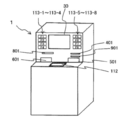
- 2A and 2B are views showing the appearance of the automatic transaction apparatus 1.
- FIG. 2A is a perspective view when the automatic transaction apparatus 1 is viewed from the front side.
- FIG. 2B is a diagram (rear view) when the automatic transaction apparatus 1 is viewed from the rear surface side.
- the automatic transaction apparatus 1 performs transaction processing with the customer (for example, cash from the customer's account) by the operation of the customer who performs the transaction processing or cooperative processing (for example, transaction processing) involving communication with the host computer 2. Withdrawals, etc.).
- the automatic transaction apparatus 1 is connected to the host computer 2 via the network N.
- the network N various network connections such as a public telephone network, a digital leased line, and the Internet can be applied.
- the automatic transaction apparatus 1 includes a control unit 10, a data recording unit 20 as a recording unit, a display operation unit 30, a card processing unit 40, a banknote deposit / withdrawal unit 50, a coin deposit / withdrawal unit 60, a journal recording unit 70, and a passbook processing unit 80. , A statement slip issuing unit 90, a staff operation unit 100, and a key input operation unit 110.
- the control unit 10 has a function of controlling the operation of each unit of the automatic transaction apparatus 1.
- the data recording unit 20 is a data storage unit that stores various types of information necessary for the control unit 10 to perform information processing.
- the data recording unit 20 can be configured by, for example, various memories. It is assumed that the data recording unit 20 of this embodiment records at least key setting information 21 as setting information. Details of the data recording unit 20 will be described later.
- the control unit 10 is realized, for example, by installing the control program of the embodiment (including a program related to each component in the control unit 10 shown in FIG. 1) or the like in an implementation configuration (computer) including a processor or the like. can do.
- the above-described program may be stored in the data recording unit 20 and read and executed by the control unit 10 when the automatic transaction apparatus 1 is activated.
- the display operation unit 30 is a device that constitutes an interface with a customer, and here, it is assumed that it is configured using a touch panel display (liquid crystal display with a touch panel).
- the display operation unit 30 can display an operation screen according to the control of the control unit 10 and perform information output and operation reception (acceptance of information input).
- the display operation unit 30 is a function of the display unit that performs display output (for example, display and output of transaction contents) to the customer and one input unit that receives operations from the customer (for example, operations using software keys).
- the specific device configuration is not limited.
- the card processing unit 40 processes the cash card inserted from the customer into the card insertion / extraction port 401.
- the banknote deposit / withdrawal unit 50 has a function of storing banknotes deposited by customers and a function of depositing banknotes stored in the customers according to the control of the control unit 10.
- the banknote depositing / withdrawing part 50 shall be able to deposit / withdraw banknotes from the banknote depositing / withdrawing port 501.
- the coin deposit / withdrawal unit 60 has a function of storing coins received from customers and a function of withdrawing stored coins to customers under the control of the control unit 10. In this embodiment, it is assumed that the coin deposit / withdrawal unit 60 can deposit / withdraw coins from the coin deposit / withdrawal port 601.
- the journal recording unit 70 performs processing for printing and recording the contents of the transaction on journal paper (for example, roll paper) according to the control of the control unit 10.
- the passbook processing unit 80 processes the passbook inserted into the passbook insertion / extraction port 801 by the customer.
- the statement slip issuing unit 90 prints the transaction result performed by the automatic transaction apparatus 1 on a print sheet under the control of the control unit 10 and discharges it from the statement slip discharge port 901.
- the clerk operation unit 100 is a device that constitutes an interface with a clerk, maintenance staff, etc. (hereinafter also referred to as “operator”) of the store where the automatic transaction apparatus 1 is installed.
- a touch panel display with a touch panel
- the liquid crystal display is used.
- the clerk operation unit 100 can display an operation screen according to the control of the control unit 10 and can perform information output and operation reception (acceptance of information input).
- the clerk operation unit 100 has a function of an operator display unit that performs display output (for example, display and output of transaction contents) to an operator and a function of an operator operation unit that receives operations from the operator.
- the device configuration is not limited.
- the arrangement position of the clerk operation unit 100 is not limited, but is arranged at a position (for example, inside a locked door (not shown)) that is not accessible by anyone other than the operator.
- the clerk operation unit 100 is disposed on the back side of the automatic transaction apparatus 1 as shown in FIG. 2B.
- the display operation unit 30 and the clerk operation unit 100 are described as separate devices.
- the operation mode can be switched between a customer and an operator using a common device. It is good also as a structure.
- the key input operation unit 110 receives an operation input from a customer by a hardware key.
- the number and arrangement of hardware keys constituting the key input operation unit 110 and the function of each hardware key are not limited.
- the key input operation unit 110 of this embodiment has a function key unit 111 and a PINPAD unit 112.
- the function key unit 111 has a plurality of hardware keys (hereinafter referred to as “function keys”) to which functions (functions) according to the control of the control unit 10 are allocated.
- the function key unit 111 has eight function keys 113-1 to 113-8.
- function keys 113-1 to 113-4 are arranged on the left side of the display operation unit 30, and function keys 113-5 to 113-8 are arranged on the right side of the display operation unit 30. Is arranged.
- the control unit 10 (transaction processing unit 11) allocates a function corresponding to the configuration of the operation screen displayed on the display operation unit 30 to each function key 113 and accepts an operation from a customer.
- the PINPAD unit 112 is a device that includes a hardware key that can accept a numeric input such as a password or transaction amount.
- FIG. 3 is a plan view of the PINPAD unit 112.
- a numeric keypad section 112a having hardware keys corresponding to numbers 0 to 9, a Cancel key 112b, a Clear key 112c, and an Enter key 112d are arranged.
- the control unit 10 (transaction processing unit 11) accepts operation inputs from the keys of the PINPAD unit 112 in accordance with the configuration of the operation screen displayed on the display operation unit 30.
- the automatic transaction apparatus 1 has a configuration including the display operation unit 30 capable of displaying an operation screen including software keys and the key input operation unit 110 configured by hardware keys.
- the input unit is configured to accept input using the keys.
- the transaction processing unit 11 performs processing related to transactions with customers.
- the transaction processing unit 11 receives, for example, an operation reception via the display operation unit 30 and the key input operation unit 110 (for example, an operation reception using an operation screen) or a host computer 2 based on information input from a customer.
- Processing such as data processing (for example, transaction processing related to transactions) and cash processing control for the banknote deposit / withdrawal unit 50 and the coin deposit / withdrawal unit 60 is performed.
- the transaction processing unit 11 When a predetermined operation is performed on the software key displayed on the display operation unit 30 or the hardware key of the clerk operation unit 100, the transaction processing unit 11 performs an unauthorized input (an operation with a high probability of unauthorized input).
- the process to detect is performed. For example, when the transaction processing unit 11 accepts an input of a transaction amount or the like, a state in which a plurality of keys (whether hardware keys or software keys are not limited) are simultaneously pressed (hereinafter, this state is referred to as “2”). Or a state where any key is continuously pressed for a predetermined time (for example, 5 seconds or longer) (hereinafter, this state is also referred to as a “long-pressed state”). In such a case, it is determined that an unauthorized input (for example, key pressing by a third party other than the customer) has been performed. That is, the transaction processing unit 11 also functions as a determination unit that detects unauthorized input.
- the transaction processing unit 11 of this embodiment performs a predetermined operation according to the setting of the key setting information 21 recorded in the data recording unit 20 when detecting that an illegal input has been made.
- FIG. 4 is an explanatory diagram showing a configuration example of the key setting information 21 according to the first embodiment.
- a value is set for the item “setting value corresponding to illegal input”.
- the “unauthorized input setting value” is an item in which a value indicating the content of the operation performed by the transaction processing unit 11 when it is detected that an unauthorized input has been performed.
- any one of values 1 to 3 is set in the “unauthorized input setting value”. Note that the number of processes corresponding to the value of “unauthorized input setting value” and the contents of the process corresponding to each setting value are not limited.
- the transaction processing unit 11 waits until the unauthorized input is canceled (for example, a double-pressed state or a long-pressed state). (Period until the state is released) Little is done (the input is invalidated even if there is another key input).
- the transaction processing unit 11 cancels (stops) the accepted transaction (for example, a cancel key).
- transaction cancellation The same processing as when the (cancel key) is pressed; hereinafter referred to as “transaction cancellation”) is performed.
- the transaction processing unit 11 terminates the transaction as a failure has occurred (hereinafter referred to as “transaction failure”). It is also referred to as “end”.
- transaction failure ends, the control unit 10 (transaction processing unit 11) enters a state in which the subsequent transaction reception is not performed.
- the control unit 10 notifies an alarm (alarm) to an external device (for example, an external device such as a host computer or a monitoring device) and calls an attendant. Processing may be performed.
- the maintenance processing unit 12 has a function of executing processing related to maintenance (system) of the automatic transaction apparatus 1. For example, the maintenance processing unit 12 performs an operation reception via the clerk operation unit 100 (for example, an operation reception using an operation screen), and executes a process according to the received operation.
- the maintenance processing unit 12 of this embodiment is assumed to function as a setting change unit that receives at least a change of the key setting information 21.
- the maintenance processing unit 12 may receive the change of the key setting information 21 by communication from an external device (for example, the host computer 2 or the like) as well as an operation from the operator.
- an external device for example, the host computer 2 or the like
- a process for accepting an operation from the operator and accepting an input (change) of the key setting information 21 is selected in the attendant operation unit 100 of the automatic transaction apparatus 1.
- the maintenance processing unit 12 of the control unit 10 starts a process of accepting the key setting, and the operation screen for receiving the unauthorized input corresponding setting value constituting the key setting information 21 (hereinafter, “ (Referred to as “illegal input corresponding set value input screen”) (S101).
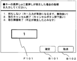
- FIG. 6 is an explanatory diagram showing an example of a setting value input screen for illegal input.
- the field F101 for accepting input of the illegal input corresponding setting value (any one of the values 1 to 3) and the illegal input corresponding setting value input in the field F101 are displayed.
- a confirmation key B101 for accepting confirmation and a cancel key B102 for canceling the input setting corresponding to illegal input and returning to the previous screen (for example, a function selection menu) are arranged.
- the enter key B101 is pressed after the set value is input to the field F101 on the unauthorized input corresponding set value input screen shown in FIG.
- the maintenance processing unit 12 of the control unit 10 acquires the input setting corresponding to illegal input and stores it in the key setting information 21 of the data recording unit 20. Register (S102) and end the process.
- the withdrawal transaction is started by a customer operation (operation on the display operation unit 30) from the customer waiting state in the automatic transaction apparatus 1, and an operation screen for guiding insertion of a cash card and a passbook is displayed on the display operation unit 30. (S201).
- a passbook is also inserted into the passbook insertion / extraction port 801 as required by the customer (S203).
- control unit 10 displays an operation screen for accepting the input of the code number on the display operation unit 30, and accepts the input of the code number from the customer (S204).
- control unit 10 displays an operation screen (hereinafter referred to as “transaction amount input screen”) for accepting an input of the withdrawal amount (transaction amount) on the display operation unit 30,
- transaction amount input screen for accepting an input of the withdrawal amount (transaction amount) on the display operation unit 30,
- the input of the withdrawal amount from the customer is accepted (S205).
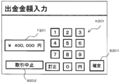
- FIG. 8 is an explanatory diagram showing a configuration example of the withdrawal amount input screen.
- the soft keypad K201 for inputting the withdrawal amount
- the field F201 for displaying the entered withdrawal amount
- the transaction is continued with the entered withdrawal amount.
- a confirmation key B201 for accepting confirmation of the transaction and a cancel key B202 for accepting cancellation of the transaction are arranged.
- the soft keypad K201 is composed of keys “0 to 9”, “circle”, and “correction”.
- the control unit 10 transaction processing unit 11
- control part 10 transaction processing part 11
- the control part 10 will start monitoring of the presence or absence of double press or long press, if the transaction amount input screen is displayed (S206).
- control unit 10 displays the transaction amount input screen, depending on whether the double press or the long press has occurred while monitoring the presence or absence of the double press or the long press. Is determined (S207).
- control part 10 shifts to processing of Step S211 mentioned below.
- the control unit 10 shifts to a process of step S208 described later.
- control unit 10 communicates with the host computer 2 to process information related to the withdrawal transaction (for example, transaction processing). ) Is executed (S208).
- transaction processing for example, transaction processing
- control unit 10 controls the statement slip issuing unit 90 to print the statement slip of the current withdrawal transaction (S209).
- control unit 10 performs control processing to discharge (return) various media (S210), and ends the transaction processing.
- control unit 10 controls the statement slip issuing unit 90 to discharge the printed statement slip.
- control unit 10 controls the card processing unit 40 to return (discharge) the cash card.
- control unit 10 controls the passbook processing unit 80 to perform a process of making a passbook entry, and then returns (discharges) the passbook.
- control part 10 controls the banknote depositing / withdrawing part 50 and the coin depositing / withdrawing part 60, and performs discharge
- step S207 the control unit 10 (transaction processing unit 11) refers to the key setting information 21 and performs illegal input.
- the corresponding setting value is confirmed (S211).
- the control unit 10 (transaction processing unit 11) proceeds to step S212 to be described later when the unauthorized input corresponding setting value is “1”, and proceeds to step S213 to be described later when the unauthorized input corresponding setting value is “2”. If the unauthorized input handling setting value is “3”, the process proceeds to step S214 described later.
- the control unit 10 (transaction processing unit 11) has a period until the unauthorized input is canceled (for example, the period until the double-pressed state or the long-pressed state is canceled). ) Wait without doing anything (even if there is another key input, the input is invalidated) (S212). And the control part 10 (transaction processing part 11) returns to the process of above-mentioned step S207, and operate
- the control unit 10 (transaction processing unit 11) cancels the transaction (interrupts acceptance of the transaction and returns the cash card, the passbook, etc.) (S213). End transaction processing.
- the control unit 10 recognizes that the transaction processing unit 11 has occurred fraud, and terminates the transaction on the assumption that a failure has occurred ( (Transaction failure end) is performed (S214), and the current transaction processing is ended.
- the automatic transaction apparatus 1 when an operation with a high probability of unauthorized input of a key by a third party (for example, double pressing or long pressing of a key) occurs, the operation according to the key setting information 21 To prevent fraud (for example, preventing fraudulent payment transactions from the customer's account).
- operation response to installation environment can be performed even when unauthorized operation of a key occurs.
- the setting value corresponding to unauthorized input is set to “3” (failure end).
- the automatic transaction apparatus 1 when receiving an input using a plurality of input keys, the safety of the transaction is improved during the transaction, and the decrease in the convenience of the customer is suppressed.
- a transaction apparatus is provided.
- the content of the key setting information 21 sets the setting value corresponding to unauthorized input to any value (any setting value from 1 to 3). It was only. That is, in the automatic transaction apparatus 1 of the first embodiment, the unauthorized input corresponding setting value is a static value. On the other hand, in the automatic transaction apparatus 1 according to the second embodiment, it is possible to dynamically change the setting value corresponding to unauthorized input according to the time zone.
- FIG. 9 is an explanatory diagram showing a configuration example of the key setting information 21 set by the automatic transaction apparatus 1 according to the second embodiment.
- a combination of a time zone and a setting value corresponding to unauthorized input can be registered.
- a time zone to be applied for each set value is set.
- the time zone corresponding to the illegal input correspondence setting value “1” is set to “08:00 to 17:00”
- the time zone corresponding to the illegal input correspondence setting value “2” is set. Is set to “17:00 to 00:00”
- the time zone corresponding to the unauthorized input handling setting value “3” is set to “00:00 to 08:00”.
- the key setting information 21 shown in FIG. 9 shows an example of registering a combination of a time zone and a set value, but it is possible to set a combination of a period such as a date and a day of the week and a set value (schedule for applying the set value). You may make it do.
- the key setting information 21 has a format for inputting a time zone for each setting value corresponding to unauthorized input, but conversely, a format for setting an unauthorized input handling setting value for each time zone may be used.
- the operator operation unit 100 of the automatic transaction apparatus 1 accepts an operation from the operator and the key setting is selected.
- the maintenance processing unit 12 of the control unit 10 causes the clerk operation unit 100 to receive an operation screen (hereinafter referred to as “time” for each unauthorized input corresponding setting value constituting the key setting information 21). (Referred to as a “band input screen”) (S301).
- FIG. 11 is an explanatory diagram showing a configuration example of a time zone input screen in the second embodiment.
- fields F301 to F303 for receiving time zone inputs corresponding to the setting values “1”, “2”, and “3” corresponding to unauthorized input are arranged. Further, in the time zone input screen shown in FIG. 11, a confirmation key B301 for accepting confirmation of the contents input in the fields F301 to F303, and a cancellation for canceling the input and returning to the previous screen (for example, a function selection menu). Key B302 is arranged. Here, it is assumed that the confirmation key B301 is pressed after the contents shown in FIG. 11 are input to the fields F301 to F303.
- the maintenance processing unit 12 of the control unit 10 acquires the contents of the input setting for handling illegal input (time zone information for each set value) and records the data. It registers in the key setting information 21 of the unit 20 (S302), and the process ends.
- the automatic transaction apparatus 1 according to the second embodiment is different from the first embodiment in that step S211 is replaced with step S401.
- the control unit 10 (transaction processing unit 11) of the second embodiment acquires a setting value corresponding to the current time according to the content of the key setting information 21 in step S401.
- the content of the key setting information 21 is the content of FIG.
- the key setting information 21 acquires “1” as the setting value corresponding to the current time.
- control unit 10 transaction processing unit 11
- process corresponding to the set value in any step of steps S212 to S214. Process
- the automatic transaction apparatus 1 can register a combination of a setting value corresponding to unauthorized input and a time zone.
- the setting value corresponding to an unauthorized input which changes according to business hours can be applied, and the convenience and the safety
- the automatic transaction apparatus 1 in order to notify a customer of information related to unauthorized input (abnormal key operation) when an unauthorized input occurs (for example, when a key is double-pressed or long-pressed).
- the operation screen hereinafter also referred to as “illegal input confirmation screen”
- the automatic transaction apparatus 1 of 3rd Embodiment it demonstrates as what can be set (it can set to the key setting information 21) whether to display an unauthorized input confirmation screen.
- FIG. 13 is an explanatory diagram showing a configuration example of the key setting information 21 according to the third embodiment.
- a parameter for setting whether or not to display an unauthorized input confirmation screen (hereinafter referred to as “confirmation screen setting value”) is added to the key setting information 21. Yes.
- the confirmation screen setting value can be set to either “1” indicating that the unauthorized input confirmation screen is not displayed or “2” indicating that the unauthorized input confirmation screen is displayed.
- the registration format of the confirmation screen setting value is not limited.
- the automatic transaction apparatus 1 may also be configured to display an unauthorized input confirmation screen according to the confirmation screen setting value.
- step S501 (such as the configuration of the setting input screen for illegal input) is the same as that in the first embodiment (the processing in step S101 described above), and thus detailed description thereof is omitted.
- control unit 10 maintenance processing unit 12 causes the attendant operation unit 100 to display an operation screen (hereinafter referred to as “confirmation screen setting value input screen”) for accepting the confirmation screen setting value (S502).
- FIG. 15 is an explanatory diagram showing a configuration example of a confirmation screen setting value input screen according to the third embodiment.
- a key B401 and a cancel key B402 for canceling the input of the confirmation screen setting value and returning to the previous screen are arranged.
- the confirmation key B401 is pressed after the confirmation screen setting value is input to the field F401 on the confirmation screen setting value input screen shown in FIG.
- the maintenance processing unit 12 of the control unit 10 displays the input values (setting values corresponding to illegal input and confirmation screen setting values) as key setting information. 21 is registered (S503), and the process is terminated.
- steps S601 and S602 are inserted before step S212 that is executed when the setting value corresponding to unauthorized input is “1” in the first embodiment. This is different from the first embodiment.
- the control unit 10 (transaction processing unit 11) of the third embodiment refers to the confirmation screen setting value of the key setting information 21 when confirming that the unauthorized input corresponding setting value is “1” in step S211 described above. (S601).
- the control unit 10 (transaction processing unit 11) does not display the unauthorized input confirmation screen. If the confirmation screen setting value of the key setting information 21 is set to “2” (setting for displaying the unauthorized input confirmation screen), the unauthorized input confirmation screen is displayed on the staff operating unit 100. It is displayed (S602).
- FIG. 17 is an explanatory diagram showing a configuration example of the unauthorized input confirmation screen.
- a message for notifying information on unauthorized input and a confirmation key B501 for receiving confirmation from the customer are arranged.
- the control unit 10 transaction processing unit 11
- proceeds to the next processing processing in step S212.
- a message for notifying information related to unauthorized input is “the key is in a state of not responding. Also, if an unintended key has been pressed, call the operator from the spot.If the key reacts without any problem, press the “Confirmed” button. ” A message is displayed.
- the unauthorized input confirmation screen includes a message indicating that unauthorized input has occurred and prompting the user to confirm that there is no problem in the surrounding state.
- an unauthorized input confirmation screen is displayed when an unauthorized input is detected.
- FIG. 18 is a block diagram showing a functional configuration of the automatic transaction apparatus 1 according to the fourth embodiment.
- FIG. 19 is an external perspective view of the automatic transaction apparatus 1 according to the fourth embodiment.
- the automatic transaction apparatus 1 according to the fourth embodiment is different from the third embodiment in that a flicker 120 (flashing lamp) and a speaker 130 are added. .
- the flicker 120 is arranged around the PINPAD unit 112 and blinks, for example, to carry out a function of making the customer pay attention to the PINPAD unit 112.
- the flicker 120 performs operations such as lighting and blinking according to the control of the control unit 10.
- the speaker 130 is arranged around the PINPAD unit 112, and plays a function of, for example, causing the customer to pay attention to the PINPAD unit 112 by outputting sound (ringing). .
- the control unit 10 (transaction processing unit 11), for example, outputs a sound based on a sound file (for example, a sound file in a WAV format (so-called WAVE file)) according to a warning sound or a warning message (for example, a warning message regarding illegal input). You may make it output from the speaker 130.
- a sound file for example, a sound file in a WAV format (so-called WAVE file)
- a warning sound or a warning message for example, a warning message regarding illegal input.
- the automatic transaction apparatus 1 in addition to displaying an unauthorized input confirmation screen when an unauthorized input occurs (for example, when a key is double-pressed or long-pressed), other output processing is performed.
- the third embodiment is different from the third embodiment in that it can be executed.
- control unit 10 (transaction processing unit 11) according to the fourth embodiment generates a warning sound from the speaker 130 according to the setting (for example, the setting of the key setting information 21) when an unauthorized input occurs. Sounding, sounding a warning message from the speaker 130, blinking of the flicker 120, and the like are possible.
- FIG. 20 is an explanatory diagram showing a configuration example of the key setting information 21 according to the fourth embodiment.
- the key setting information 21 includes a parameter (hereinafter referred to as “warning sound setting value”) for setting whether or not to sound a warning sound from the speaker 130. Have been added.
- the warning sound setting value can be set to either “1” indicating that the warning sound setting value is not sounded or “2” indicating that the warning sound is sounded.
- the registration format of the warning sound setting value is not limited.
- warning message setting value a parameter for setting whether or not the warning message from the speaker 130 is sounded in the key setting information 21 (hereinafter referred to as “warning message setting value”). ) Has been added.
- the warning message setting value can be set to either “1” indicating that the warning message is not sounded or “2” indicating that the warning message is sounded.
- the registration format of the warning message setting value is not limited.
- a parameter for setting whether or not the flicker 120 blinks is added to the key setting information 21. Yes.
- the flicker setting value can be set to either “1” indicating that the flicker 120 is not blinked or “2” indicating that the flicker 120 is blinking.
- the flicker setting value registration format is not limited.
- an illegal input when an illegal input occurs, an unauthorized input confirmation screen is displayed, a warning sound is emitted from the speaker 130, and a warning is issued from the speaker 130 according to the setting.
- Four operations of sounding a message and blinking flicker 120 are possible, but only a part of the operations may be applied, or may be applied in combination with other operations.
- step S701 (such as the configuration of the setting input screen for illegal input) is the same as that in the first embodiment (the processing in step S101 described above), and thus detailed description thereof is omitted.
- control unit 10 maintenance processing unit 12
- the process of displaying the confirmation screen set value input screen on the clerk operation unit 100 and accepting the input of the confirmation screen set value is the same as that in step S502 described above, and detailed description thereof is omitted.
- control unit 10 maintenance processing unit 12
- displays an operation screen hereinafter referred to as “warning sound setting value input screen” for accepting the warning sound setting value on the staff operating unit 100 to set the warning sound.
- An input of a value is accepted (S703).
- FIG. 22 is an explanatory diagram showing a configuration example of a warning sound set value input screen according to the fourth embodiment.
- a key B501 and a cancel key B502 for canceling the input of the warning sound set value and returning to the previous screen are arranged.
- the enter key B501 is pressed after the warning sound setting value is input to the field F501 on the warning sound setting value input screen shown in FIG.
- control unit 10 maintenance processing unit 12 displays an operation screen (hereinafter referred to as “warning message setting value input screen”) for accepting the warning message setting value on the staff operating unit 100 to set the warning message.
- An input of a value is accepted (S704).
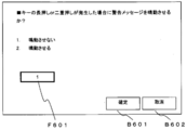
- FIG. 23 is an explanatory diagram showing a configuration example of a warning message setting value input screen according to the fourth embodiment.
- a key B601 and a cancel key B602 for canceling the input of the warning message set value and returning to the previous screen are arranged.
- the control unit 10 maintenance processing unit 12 displays an operation screen for receiving the flicker setting value (hereinafter referred to as “flicker setting value input screen”) on the staff operation unit 100 to input the flicker setting value. Is accepted (S705).
- FIG. 24 is an explanatory diagram showing a configuration example of a flicker setting value input screen according to the fourth embodiment.
- a cancel key B702 for canceling the input of the flicker setting value and returning to the previous screen for example, a function selection menu.
- the maintenance processing unit 12 of the control unit 10 converts the input values (incorrect input correspondence setting value, confirmation screen setting value, warning sound setting value, warning message setting value, and flicker setting value) into key setting information. 21 is registered (S706), and the process is terminated.
- steps S801 to S806 are performed after the processes of steps S212, S601, and S602 that are executed when the setting value corresponding to unauthorized input is “1” in the third embodiment. It is different from the third embodiment in that it is inserted.
- the processing (S601, S60, S801 to S806) executed when the setting value corresponding to unauthorized input shown in FIG. 26 is “1” will be mainly described.
- the controller 10 (transaction processor 11) of the fourth embodiment confirms that the unauthorized input corresponding setting value is “1” in step S211, the controller 10 (transaction processor 11) refers to the confirmation screen setting value of the key setting information 21. (S601).
- the control unit 10 (transaction processing unit 11) does not display the unauthorized input confirmation screen. If the confirmation screen setting value of the key setting information 21 is set to “2” (setting to display the unauthorized input confirmation screen), the unauthorized operation confirmation unit 100 confirms the unauthorized input. The display of the screen is started (S602), and the process proceeds to step S801 described later. Since the unauthorized input confirmation screen is the same as that in FIG. 17 described above, detailed description thereof is omitted.
- step S801 the control unit 10 (transaction processing unit 11) refers to the warning sound setting value of the key setting information 21.
- the control unit 10 (transaction processing unit 11) does not sound the warning sound and does the following steps.
- the warning sound setting value of the key setting information 21 is set to “2” (setting to sound the warning sound)
- the warning sound is started to be generated in the speaker 130 (S802).
- the process proceeds to step S803 to be described later.
- the control unit 10 (transaction processing unit 11) causes the speaker 130 to output sound based on an audio file (for example, a Wave file) corresponding to the warning sound.
- an audio file for example, a Wave file
- various warning sounds for example, an alarm sound output when performing error display on various computers
- control unit 10 refers to the warning message setting value of the key setting information 21.
- the control unit 10 (transaction processing unit 11) does not sound the warning message and performs the steps described later.
- the process proceeds to S805, and if the warning message setting value of the key setting information 21 is set to “2” (setting to sound a warning message), the warning message is started to be sounded by the speaker 130 (S804).
- the process proceeds to step S805 described later.
- the control unit 10 (transaction processing unit 11) causes the speaker 130 to output sound based on an audio file (for example, a Wave file) corresponding to the warning message.
- the content of the warning message is not limited, but may be a message displayed on the confirmation screen shown in FIG. 17, for example.
- control unit 10 (transaction processing unit 11) refers to the flicker setting value of the key setting information 21.
- the control unit 10 performs the process of step S212 without causing the flicker 120 to blink.
- the flicker setting value of the key setting information 21 is set to “2” (setting to blink the flicker 120)
- the flicker 120 starts blinking (S806), and the process proceeds to step S212. .
- step S212 the control unit 10 (transaction processing unit 11) waits without doing anything until the unauthorized input is canceled (for example, the period until the double-pressed state or the long-pressed state is canceled). Then, after the unauthorized input is released, the process proceeds to step S207.
- the control unit 10 transmits each operation (display of an unauthorized input confirmation screen, sound of a warning sound, sound of a warning message, and flicker) performed along with the unauthorized input. 120 may be stopped and then the process may proceed to step S207.
- the automatic transaction apparatus 1 of the fourth embodiment convenience is improved by making it possible to flexibly set an operation performed when an illegal input occurs according to the setting contents of the key setting information 21.
- the flicker 120 and the speaker 130 output, so it is possible to call attention to the surroundings and reduce fraudulent payment transactions.
- the automatic transaction apparatus 1 of each of the above embodiments has a configuration including the display operation unit 30 capable of displaying an operation screen including software keys and a key input operation unit 110 configured by hardware keys. Although an input unit for receiving an input from a customer is configured, the key input operation unit 110 may be omitted and the input unit may be configured with software keys for all keys.
- the key input operation unit 110 (the function key unit 111 and the PINPAD unit 112) is omitted.
- the size of the display operation unit 30 may be increased so that all omitted hardware keys can be displayed as software keys as shown in FIG.
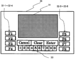
- eight function keys 31-1 to 32-8 configured by software keys and a PINPAD 33 configured by software keys are provided around an area 31 for displaying an operation screen. Has been placed.
- the control unit 10 transaction processing unit 11
- control unit 10 may monitor both the long-pressed state and the double-pressed state or only one of them. .
Landscapes
- Physics & Mathematics (AREA)
- General Physics & Mathematics (AREA)
- Business, Economics & Management (AREA)
- Accounting & Taxation (AREA)
- Finance (AREA)
- Financial Or Insurance-Related Operations Such As Payment And Settlement (AREA)
Abstract
複数のキーを備える入力部と、複数のキーが同時に押下された二重押し状態、又はいずれかのキーが所定時間以上継続して押下された長押し状態のいずれか一方を監視し、二重押し状態又は長押し状態を検知した場合に不正入力が行われたと判断する判断手段と、判断手段で、不正入力が行われたと判断された場合の処理内容を示す設定情報を記録する記録部と、入力部を用いて顧客との取引処理を行うものであって、判断手段で、不正入力が行われたと判断された場合に、記録部で記録された設定情報に従った動作を行う取引処理手段とを有する取引装置を提供する。
Description
本発明は、取引装置に関し、例えば、金融機関やコンビニエンスストア等に設置される自動取引装置(ATM:Automated Teller Machine)に適用し得る。
従来の自動取引装置では、ユーザインタフェースとして、操作画面(例えば、ソフトウェアキーを含むGUI)を表示するディスプレイに加えて、ハードウェアキー(例えば、ファンクションキー)を備える装置が存在する(特開2002-32833号公報(特許文献1参照))。
従来の自動取引装置では、顧客との取引時に、例えば、タッチパネルディスプレイ上に表示されたソフトウェアキー(例えば、操作画面上に表示されたテンキー)やハードウェアキー(例えば、PINPAD等のハードウェアのテンキー)を用いて、暗証番号や金額等の情報入力を受け付ける。
ところで、従来の自動取引装置では、暗証番号や金額等の数字入力を受け付ける場合、ソフトウェアキー(タッチパネルディスプレイ)とハードウェアキーで両方同時に入力受付を開始する。そして、従来の自動取引装置では、通常ソフトウェアキーとハードウェアキーの両方について入力が行われた場合は、入力が無効状態(キーを押下したも反応がない状態)となる。すなわち、従来の自動取引装置において、ソフトウェアキーとハードウェアキーの両方で入力が行われた場合、後から入力が開始されたデバイスについては操作を行っても操作画面上で反応がないという結果となる。
したがって、例えば、正規利用者に対して不正取引を考えている第三者が何れかのソフトウェアキー又はハードウェアキー(ファンクションキー)を押下した状態とすると、正規利用者がキーを押下してもキーの反応が無いという状態となる。この場合、正規利用者がキーを押下してもキーの反応が無く、自動取引装置が無応答状態に見える状態となる。そのような状態になると、不正取引を考えている第三者は正規利用者に対して、自動取引装置の故障のため行員を呼びに行かせて、その場を離れている間に、不正取引を考えている第三者が改めて支払い金額を入力し、現金を受け取り、支払い取引を完了させてしまうことが可能となる場合がある。また、正規利用者がカードや通帳を挿入したまま、自動取引装置の傍から離れる場合、そのカードや通帳は、不正行為者に持ち去られる可能性がある。
一方で、ソフトウェアキーとハードウェアキーの両方について同時に入力可能とした場合、誤操作により顧客が意図しない数字入力が行われてしまい、利便性を損なう可能性がある。
以上のような問題に鑑みて、複数のキーを用いた入力を受付ける際に、取引の安全性(セキュリティ)を向上させる取引装置(例えば、自動取引装置)が望まれている。
本発明の取引装置は、(1)複数のキーを備える入力部と、(2)少なくとも複数の上
記キーが同時に押下された二重押し状態、又はいずれかの上記キーが所定時間以上継続し
て押下された長押し状態のいずれか一方を監視し、二重押し状態又は長押し状態のいずれ
かを検知した場合に不正入力が行われたと判断する判断手段と、(3)上記判断手段で、
不正入力が行われたと判断された場合の処理内容を示す設定情報を記録する記録部と、(
4)上記入力部を用いて顧客との取引処理を行うものであって、上記判断手段で、不正入
力が行われたと判断された場合に、上記記録部で記録された設定情報に従った動作を行う
取引処理手段とを有することを特徴とする。
記キーが同時に押下された二重押し状態、又はいずれかの上記キーが所定時間以上継続し
て押下された長押し状態のいずれか一方を監視し、二重押し状態又は長押し状態のいずれ
かを検知した場合に不正入力が行われたと判断する判断手段と、(3)上記判断手段で、
不正入力が行われたと判断された場合の処理内容を示す設定情報を記録する記録部と、(
4)上記入力部を用いて顧客との取引処理を行うものであって、上記判断手段で、不正入
力が行われたと判断された場合に、上記記録部で記録された設定情報に従った動作を行う
取引処理手段とを有することを特徴とする。
本発明によれば、複数のキーを用いた入力を受付ける際に、取引の安全性を向上させる
取引装置を提供することができる。
取引装置を提供することができる。
(A)第1の実施形態
以下、本発明による取引装置の第1の実施形態を、図面を参照しながら詳述する。以下では、本発明の取引装置を自動取引装置に適用する例について説明する。
以下、本発明による取引装置の第1の実施形態を、図面を参照しながら詳述する。以下では、本発明の取引装置を自動取引装置に適用する例について説明する。
(A-1)第1の実施形態の構成
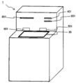
図1は、第1の実施形態の自動取引装置1の機能的構成及び周辺装置の接続構成について示したブロック図である。図2A、Bは、自動取引装置1の外観を示す図である。図2Aは、自動取引装置1を正面側から見た場合の斜視図である。図2Bは、自動取引装置1を背面側から見た場合の図(背面図)である。
図1は、第1の実施形態の自動取引装置1の機能的構成及び周辺装置の接続構成について示したブロック図である。図2A、Bは、自動取引装置1の外観を示す図である。図2Aは、自動取引装置1を正面側から見た場合の斜視図である。図2Bは、自動取引装置1を背面側から見た場合の図(背面図)である。
自動取引装置1は、取引処理を行う顧客の操作や、ホストコンピュータ2との通信を伴う協働処理(例えば、トランザクション処理)により、当該顧客との取引処理(例えば、当該顧客の口座からの現金の出金等)を行うものである。
自動取引装置1は、ネットワークNを介してホストコンピュータ2と接続されている。ネットワークNは、例えば、公衆電話網、デジタル専用回線、インターネット等の種々のネットワーク接続を適用することができる。
自動取引装置1は、制御部10、記録部としてのデータ記録部20、表示操作部30、カード処理部40、紙幣入出金部50、硬貨入出金部60、ジャーナル記録部70、通帳処理部80、明細票発行部90、係員操作部100、及びキー入力操作部110を有している。
制御部10は、自動取引装置1の各部の動作を制御する機能を担っている。また、データ記録部20は、制御部10が情報処理を行うために必要な各種情報等を格納するデータ記憶手段であり、例えば、各種メモリ等により構成することができる。なお、この実施形態のデータ記録部20では、少なくとも設定情報としてのキー設定情報21を記録しているものとする。データ記録部20の詳細については後述する。
制御部10は、例えば、プロセッサ等を含むプログラムの実施構成(コンピュータ)に実施形態の制御プログラム(図1に示す制御部10内部の各構成要素に係るプログラムを含む)等をインストールすることにより実現することができる。上述のプログラムは、例えば、データ記録部20に記憶しておき、自動取引装置1が起動したときに、制御部10が読み込んで実行するようにしても良い。
表示操作部30は、顧客とのインタフェースを構成するデバイスであり、ここでは、タッチパネルディスプレイ(タッチパネル付の液晶ディスプレイ)を用いて構成されているものとする。表示操作部30は、制御部10の制御に応じた操作画面を表示して、情報出力及び操作受付(情報入力の受付け)を行うことが可能である。言い換えると、表示操作部30は、顧客に表示出力(例えば、取引の内容等を表示出力)する表示部の機能と、顧客からの操作(例えばソフトウェアキーを用いた操作)を受付ける入力部の一部の機能を担っており、具体的なデバイス構成については限定されないものである。
カード処理部40は、顧客からカード挿入排出口401に挿入されたキャッシュカードの処理を行うものである。
紙幣入出金部50は、制御部10の制御に応じて、顧客から入金された紙幣を収納する機能と、収納されている紙幣を顧客に出金する機能を担っている。この実施形態では、紙幣入出金部50は、紙幣入出金口501から紙幣の入出金を行うことが可能であるものとする。
硬貨入出金部60は、制御部10の制御に応じて、顧客から入金された硬貨を収納する機能と、収納されている硬貨を顧客に出金する機能を担っている。この実施形態では、硬貨入出金部60は、硬貨入出金口601から硬貨の入出金を行うことが可能であるものとする。
ジャーナル記録部70は、制御部10の制御に応じて、取引の内容をジャーナル用紙(例えばロール紙等)に印字記録する処理を行う。
通帳処理部80は、顧客から通帳挿入排出口801に挿入された通帳の処理を行うものである。
明細票発行部90は、制御部10の制御に応じて、当該自動取引装置1で行われた取引結果について印刷用紙に印字して、明細票排出口901から排出を行うものである。
係員操作部100は、当該自動取引装置1が設置された店舗の係員や保守員等(以下、「オペレータ」とも呼ぶ)とのインタフェースを構成するデバイスであり、ここでは、タッチパネルディスプレイ(タッチパネル付の液晶ディスプレイ)を用いて構成されているものとする。係員操作部100は、制御部10の制御に応じた操作画面を表示して、情報出力及び操作受付(情報入力の受付け)を行うことが可能である。言い換えると、係員操作部100は、オペレータに表示出力(例えば、取引の内容等を表示出力)するオペレータ表示部の機能と、オペレータからの操作を受付けるオペレータ操作部の機能を担っており、具体的なデバイス構成については限定されないものである。係員操作部100の配置位置は限定されないものであるが、オペレータ以外がアクセスできない位置(例えば、図示しない施錠された扉内等)に配置されている。この実施形態の例では、係員操作部100は、図2Bに示すように、係員操作部100は、自動取引装置1の背面側に配置されているものとする。また、この実施形態では、表示操作部30と係員操作部100とは別個のデバイスであるものとして説明するが、共通するデバイスを用いて顧客用とオペレータ用で動作モードを切り替えて使用可能とする構成としてもよい。
キー入力操作部110は、ハードウェアキーにより顧客からの操作入力を受付けるものである。キー入力操作部110を構成するハードウェアキーの数や配置、各ハードウェアキーの機能については限定されないものである。この実施形態のキー入力操作部110は、ファンクションキー部111とPINPAD部112とを有している。
ファンクションキー部111は、制御部10の制御に応じた機能(ファンクション)が割り振られる複数のハードウェアキー(以下、「ファンクションキー」と呼ぶ)を有している。この実施形態では、ファンクションキー部111は、8つのファンクションキー113-1~113-8を有している。この実施形態では、図2Aに示すように、表示操作部30の左側にファンクションキー113-1~113-4が配置されており、表示操作部30の右側にファンクションキー113-5~113-8が配置されている。制御部10(取引処理部11)は、表示操作部30に表示する操作画面の構成に応じた機能を各ファンクションキー113に割当てて顧客からの操作を受付ける。
PINPAD部112は、暗証番号や取引金額等の数字入力を受付けることが可能なハードウェアキーを備えるデバイスである。
図3は、PINPAD部112の平面図である。
図3に示すPINPAD部112には、0~9の各数字に対応したハードウェアキーを有するテンキー部112aと、Cancelキー112bと、Clearキー112cとEnterキー112dとが配置されている。制御部10(取引処理部11)は、表示操作部30に表示する操作画面の構成に応じてPINPAD部112の各キーからの操作入力を受付ける。
以上のように、自動取引装置1では、ソフトウェアキーを含む操作画面を表示可能な表示操作部30と、ハードウェアキーにより構成されたキー入力操作部110を含む構成により、顧客からの入力(複数のキーを用いた入力)を受付ける入力部が構成されている。
取引処理部11は、顧客との取引に係る処理を行う。取引処理部11は、例えば、表示操作部30及びキー入力操作部110を介した操作受付(例えば、操作画面を用いた操作受付)や、顧客から入力された情報に基づいたホストコンピュータ2とのデータ処理(例えば、取引に係るトランザクション処理)や、紙幣入出金部50及び硬貨入出金部60に対する現金処理制御等の処理を行う。
取引処理部11は、表示操作部30に表示されたソフトウェアキーや、係員操作部100のハードウェアキーについて所定の操作が行われた場合、当該操作を不正入力(不正入力の蓋然性が高い操作)として検出する処理を行う。例えば、取引処理部11は、取引金額等の入力を受付ける際に、複数のキー(ハードウェアキーであるかソフトウェアキーであるかを限定しない)を同時押下した状態(以下、この状態を「二重押し状態」とも呼ぶ)又は、いずれかのキーを所定時間以上(例えば、5秒以上)継続して押下した状態(以下、この状態を「長押し状態」とも呼ぶ)のいずれかの状態となった場合に不正入力(例えば、顧客以外の第三者によるキーの押下)が行われたものとして判断する。すなわち、取引処理部11は、不正入力を検知する判断手段としても機能する。
そして、この実施形態の取引処理部11は、不正入力が行われたと検知した場合、データ記録部20に記録されたキー設定情報21の設定に従った所定の動作を行う。
図4は、第1の実施形態に係るキー設定情報21の構成例について示した説明図である。
図4に示すキー設定情報21では、「不正入力対応設定値」の項目について値(パラメータ)が設定されている。「不正入力対応設定値」は、不正入力が行われたと検知された場合に取引処理部11が行う動作の内容を示す値が設定される項目である。
この実施形態では、「不正入力対応設定値」には1~3のいずれかの値が設定されるものとして説明する。なお、「不正入力対応設定値」の値に対応する処理の数や各設値に対応する処理の内容については限定されないものである。
この実施形態では、キー設定情報21の不正入力対応設定値に「1」が設定されていた場合、取引処理部11は、不正入力が解除されるまでの(例えば、二重押し状態や長押し状態が解除されるまでの期間)何もしない(さらに他のキー入力があっても入力を無効とする)ものとする。
また、この実施形態では、キー設定情報21の不正入力対応設定値に「2」が設定されていた場合、取引処理部11は、受付中の取引をキャンセル(中止)する処理(例えば、取消キー(キャンセルキー)が押下された場合と同様の処理;以下「取引キャンセル」とも呼ぶ)を行うものとする。
さらに、この実施形態ではキー設定情報21の不正入力対応設定値に「3」が設定されていた場合、取引処理部11は、障害が発生したものとして取引を終了する処理(以下、「取引障害終了」とも呼ぶ)を行うものとする。以取引障害終了とした場合、制御部10(取引処理部11)は、後の取引受付を行わない状態となる。また、取引障害終了とした場合、制御部10(取引処理部11)は、外部装置(例えば、ホストコンピューや監視装置等の外部装置)にアラーム(警報)を通知して、係員を呼ぶ等の処理を行うようにしてもよい。
保守処理部12は、当該自動取引装置1の保守(システム)に係る処理を実行する機能を担っている。保守処理部12は、例えば、係員操作部100を介した操作受付(例えば、操作画面を用いた操作受付)を行い、受付けた操作に応じた処理を実行する。この実施形態の保守処理部12は、少なくとも、キー設定情報21の変更を受け付ける設定変更手段として機能するものとする。
なお、保守処理部12は、オペレータからの操作だけでなく、外部装置(例えば、ホストコンピュータ2等)から通信によりキー設定情報21の変更受付けを行うようにしてもよい。
(A-2)第1の実施形態の動作
次に、以上のような構成を有する第1の実施形態の自動取引装置1の動作を説明する。
次に、以上のような構成を有する第1の実施形態の自動取引装置1の動作を説明する。
まず、ここでは、第1の実施形態の自動取引装置1において、キー設定情報21が設定される場合の動作について図5を用いて説明する。
まず、自動取引装置1の係員操作部100において、オペレータからの操作を受付け、キー設定情報21の入力(変更)を受け付ける処理(以下、「キー設定」と呼ぶ)が選択されたものとする。これにより、制御部10の保守処理部12は、キー設定を受付ける処理を開始し、係員操作部100に、キー設定情報21を構成する不正入力対応設定値を受け付けるための操作画面(以下、「不正入力対応設定値入力画面」と呼ぶ)を表示させる(S101)。
図6は、不正入力対応設定値入力画面の例について示した説明図である。
図6に示す不正入力対応設定値入力画面では、不正入力対応設定値(1~3のいずれかの値)の入力を受け付けるためのフィールドF101と、フィールドF101に入力された不正入力対応設定値の確定を受け付ける確定キーB101と、入力された不正入力対応設定値を取消して前画面等(例えば、機能の選択メニュー等)に戻るための取消キーB102とが配置されている。ここでは、図6に示す不正入力対応設定値入力画面でフィールドF101に設定値が入力された後確定キーB101が押下されたものとする。
不正入力対応設定値入力画面で確定キーB101が押下されると、制御部10の保守処理部12は、入力された不正入力対応設定値を取得して、データ記録部20のキー設定情報21に登録し(S102)、処理を終了する。
以上のように、第1の実施形態の自動取引装置1では、キー設定情報21の内容が登録されるものとする。
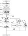
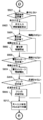
次に、自動取引装置1が顧客と取引を行う際の処理の例について図7のフローチャートを用いて説明する。
まず、自動取引装置1で顧客待ちの状態から顧客の操作(表示操作部30に対する操作)により、出金取引が開始され、キャッシュカード及び通帳の挿入を誘導する操作画面が表示操作部30に表示されたものとする(S201)。
次に、顧客により、キャッシュカードがカード挿入排出口401に挿入されたものとする(S202)。
また、このとき、顧客の必要に応じて通帳も通帳挿入排出口801に挿入される(S203)。
次に、制御部10(取引処理部11)は、表示操作部30に暗証番号の入力を受付ける操作画面を表示して、顧客から暗証番号の入力を受付ける(S204)。
次に、制御部10(取引処理部11)は、表示操作部30に、出金金額(取引金額)の入力を受付ける操作画面(以下、「取引金額入力画面」と呼ぶ)を表示して、顧客から出金金額の入力を受付ける(S205)。
図8は、出金金額入力画面の構成例について示した説明図である。図8に示す出金金額入力画面では、出金金額を入力するためのソフトキーパッドK201と、入力された出金金額を表示するためのフィールドF201と、入力された出金金額で取引を続行することの確認を受付けるための確定キーB201と、取引の中止を受付けるための取消キーB202とが配置されている。ソフトキーパッドK201は、「0~9」、「円」、「訂正」のキーにより構成されている。なお、制御部10(取引処理部11)は、出金金額入力画面を表示している状態において、出金金額入力画面上のソフトキーだけでなく、PINPAD部112からの入力も受付け可能な状態で制御する。
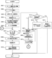
そして、制御部10(取引処理部11)は、取引金額入力画面を表示すると、二重押し又は長押しの有無の監視を開始する(S206)。
そして、制御部10(取引処理部11)は、取引金額入力画面を表示中に、二重押し又は長押しの有無を監視中に二重押し又は長押しが発生したか否かに応じてその後の動作を判断する(S207)。二重押し又は長押しが発生した場合、制御部10(取引処理部11)は、後述するステップS211の処理に移行する。一方、二重押し又は長押しが発生せずに取引金額の入力が終了した場合には、制御部10(取引処理部11)は、後述するステップS208の処理に移行することになる。
二重押し又は長押しが発生せずに取引金額の入力が終了した場合、制御部10(取引処理部11)は、ホストコンピュータ2と通信して、出金取引に関する情報処理(例えば、トランザクション処理)を実行する(S208)。ここでは、制御部10(取引処理部11)とホストコンピュータ2との間の出金取引の処理は成功したものとして以下の説明を行う。
次に、制御部10(取引処理部11)は、明細票発行部90を制御して、今回の出金取引の明細票を印字させる(S209)。
次に、制御部10(取引処理部11)は、各種媒体を排出(返却)するように制御処理を行い(S210)取引処理を終了する。このとき、制御部10(取引処理部11)は、明細票発行部90を制御して印字した明細票を排出させる。また、制御部10(取引処理部11)は、カード処理部40を制御してキャッシュカードを返却(排出)させる。さらに、制御部10(取引処理部11)は、通帳が挿入されている場合、通帳処理部80を制御して、通帳に記帳させる処理を行った後、当該通帳の返却(排出)を実行させる。さらにまた、制御部10(取引処理部11)は、紙幣入出金部50及び硬貨入出金部60を制御して、今回の出金取引で出金する現金の排出を実行させる。
一方、上述のステップS207で、取引金額入力画面を表示中に、二重押し又は長押しが発生した場合、制御部10(取引処理部11)は、キー設定情報21を参照して、不正入力対応設定値を確認する(S211)。そして、制御部10(取引処理部11)は、不正入力対応設定値が「1」の場合後述するステップS212に移行し、不正入力対応設定値が「2」の場合後述するステップS213に移行し、不正入力対応設定値が「3」の場合後述するステップS214に移行する。
不正入力対応設定値が「1」の場合、制御部10(取引処理部11)は、不正入力が解除されるまで(例えば、二重押しの状態や長押しの状態が解除されるまでの期間)何もせずに待機する(さらに他のキー入力があっても入力を無効とする)ものとする(S212)。そして、制御部10(取引処理部11)は、二重押し又は長押しが解除された後、上述のステップS207の処理に戻って動作する。
不正入力対応設定値が「2」の場合、制御部10(取引処理部11)は、取引をキャンセル(取引の受付を中断してキャッシュカードや通帳等を返却)を行い(S213)、今回の取引処理を終了する。
不正入力対応設定値が「3」の場合、制御部10(取引処理部11)は、取引処理部11は、不正が発生したものと認識し、障害が発生したものとして取引を終了する処理(取引障害終了)を行い(S214)、今回の取引処理を終了する。
(A-3)第1の実施形態の効果
第1の実施形態によれば、以下のような効果を奏することができる。
第1の実施形態によれば、以下のような効果を奏することができる。
第1の実施形態の自動取引装置1では、第三者によるキーの不正入力の蓋然性の高い操作(例えば、キーの二重押しや長押し)が発生した場合、キー設定情報21に応じた動作を行うことにより、不正行為を防止(例えば、顧客の口座からの不正な支払い取引を防止)する。これにより、第1の実施形態の自動取引装置1では、キーの不正操作が発生した場合でも、設置環境に応じた動作(対応)を行うことができる。例えば、係員が存在する店舗(有人店舗)に設置された自動取引装置1については、すぐに係員が駆けつけることができるため、例えば、不正入力対応設定値を「3」(障害終了)とすることで、確実に不正入力を抑止すると共にすぐに取引を再開(例えば、装置の再起動等を実行)させることができる。一方、係員が存在しない店舗(無人店舗)に設置された自動取引装置1については、すぐに係員が駆けつけることができないが、例えば、不正入力対応設定値を「2」(取引キャンセル)とすることで、不正入力を抑止しつつ取引を継続することが可能となる。
以上のように、第1の実施形態の自動取引装置1では、複数の入力キーを用いた入力を受付ける際に、取引の際に取引の安全性を向上させつつ、顧客の利便性低下を抑制する取引装置を提供する。
(B)第2の実施形態
以下、本発明による取引装置の第2の実施形態を、図面を参照しながら詳述する。以下では、本発明の取引装置を自動取引装置に適用する例について説明する。
以下、本発明による取引装置の第2の実施形態を、図面を参照しながら詳述する。以下では、本発明の取引装置を自動取引装置に適用する例について説明する。
(B-1)第2の実施形態の構成
第2の実施形態の自動取引装置1の構成についても、上述の図1、図2A,Bを用いて示すことができる。以下では、第2の実施形態の自動取引装置1について第1の実施形態との差異を説明する。
第2の実施形態の自動取引装置1の構成についても、上述の図1、図2A,Bを用いて示すことができる。以下では、第2の実施形態の自動取引装置1について第1の実施形態との差異を説明する。
第1の実施形態の自動取引装置1では、図4に示すように、キー設定情報21の内容が不正入力対応設定値をいずれかの値(1~3のいずれかの設定値)に設定するのみであった。すなわち、第1の実施形態の自動取引装置1では、不正入力対応設定値が静的な値となっていた。これに対して、第2の実施形態の自動取引装置1では、不正入力対応設定値を時間帯に応じて動的に変更することが可能となっている。
図9は、第2の実施形態の自動取引装置1で設定されるキー設定情報21の構成例について示した説明図である。
図9に示すように、第2の実施形態のキー設定情報21では、時間帯と不正入力対応設定値との組合せが登録可能となっている。具体的には、図9に示すキー設定情報21では、設定値ごとに適用する時間帯が設定されている。図9に示すキー設定情報21では、不正入力対応設定値「1」に対応する時間帯を「08:00~17:00」に設定し、不正入力対応設定値「2」に対応する時間帯を「17:00~00:00」に設定し、不正入力対応設定値「3」に対応する時間帯を「00:00~08:00」に設定している。
図9に示すキー設定情報21では、時間帯と設定値の組合せを登録する例について示しているが、日時や曜日等の期間と設定値の組合せ(設定値を適用するスケジュール)を設定可能とするようにしてもよい。また、図9では、キー設定情報21は、不正入力対応設定値ごとの時間帯を入力する形式となっているが、逆に時間帯ごとに不正入力対応設定値を設定する形式としてもよい。
(B-2)第2の実施形態の動作
次に、以上のような構成を有する第2の実施形態の自動取引装置1の動作を説明する。
次に、以上のような構成を有する第2の実施形態の自動取引装置1の動作を説明する。
まず、ここでは、第2の実施形態の自動取引装置1において、キー設定情報21が設定される場合の動作について図10を用いて説明する。
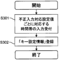
まず、自動取引装置1の係員操作部100において、オペレータからの操作を受付け、キー設定が選択されたものとする。キー設定が選択されると、制御部10の保守処理部12は、係員操作部100に、キー設定情報21を構成する不正入力対応設定値ごとの時間帯入力を受付ける操作画面(以下、「時間帯入力画面」と呼ぶ)を表示させる(S301)。
図11は、第2の実施形態における時間帯入力画面の構成例について示した説明図である。
図11に示す時間帯入力画面では、不正入力対応設定値「1」、「2」、「3」のそれぞれに対応する時間帯入力を受付けるためのフィールドF301~F303が配置されている。また、図11に示す時間帯入力画面では、フィールドF301~F303に入力された内容の確定を受け付ける確定キーB301と、入力を取消して前画面(例えば、機能の選択メニュー等)に戻るための取消キーB302とが配置されている。ここでは、図11に示す内容がフィールドF301~F303に入力された後確定キーB301が押下されたものとする。
時間帯入力画面で確定キーB301が押下されると、制御部10の保守処理部12は、入力された不正入力対応設定の内容(設定値ごとの時間帯の情報)を取得して、データ記録部20のキー設定情報21に登録し(S302)、処理を終了する。
以上のように、第2の実施形態の自動取引装置1では、キー設定情報21の内容が登録されるものとする。
次に、自動取引装置1が顧客と取引を行う際の処理の例について図12のフローチャートを用いて説明する。図12のフローチャートでは、第1の実施形態のフローチャート(上述の図7のフローチャート)と同様の処理を行うステップには同一のステップ番号(符号)を付している。以下では、第2の実施形態の自動取引装置1について第1の実施形態との差異部分のみを説明する。
第2の実施形態の自動取引装置1では、ステップS211がステップS401に置き換わっている点で第1の実施形態と異なっている。
第2の実施形態のキー設定情報21は、上述の図9に示すように、設定値ごとに対応する時間帯が設定されている。そこで、第2の実施形態の制御部10(取引処理部11)は、ステップS401において、キー設定情報21の内容に従って現在時刻に対応する設定値を取得する。例えば、キー設定情報21の内容が図9の内容となっていた場合を想定する。例えば、現在時刻が「10:00」だった場合、キー設定情報21は現在時刻に対応する設定値として「1」を取得することになる。
第2の実施形態の制御部10(取引処理部11)は、ステップS401において、以上のような処理で設定を取得すると、当該設定値に対応した処理(ステップS212~S214のいずれかのステップの処理)に移行する。
(B-3)第2の実施形態の効果
第2の実施形態によれば、第1の実施形態の効果に加えて以下のような効果を奏することができる。
第2の実施形態によれば、第1の実施形態の効果に加えて以下のような効果を奏することができる。
第2の実施形態の自動取引装置1では、自動取引装置1に、不正入力対応設定値と時間帯との組み合わせを登録可能としている。これにより、第2の実施形態の自動取引装置1では、業務時間に応じて異なる不正入力対応設定値を適用可能とし、利便性や取引の安全性(セキュリティ)を高めることができる。
(C)第3の実施形態
以下、本発明による取引装置の第3の実施形態を、図面を参照しながら詳述する。以下では、本発明の取引装置を自動取引装置に適用する例について説明する。
以下、本発明による取引装置の第3の実施形態を、図面を参照しながら詳述する。以下では、本発明の取引装置を自動取引装置に適用する例について説明する。
(C-1)第3の実施形態の構成
第3の実施形態の自動取引装置1の構成についても、上述の図1、図2A,Bを用いて示すことができる。以下では、第3の実施形態の自動取引装置1について第1の実施形態との差異を説明する。
第3の実施形態の自動取引装置1の構成についても、上述の図1、図2A,Bを用いて示すことができる。以下では、第3の実施形態の自動取引装置1について第1の実施形態との差異を説明する。
第3の実施形態の自動取引装置1では、不正入力の発生時(例えば、キーの二重押しや長押しの発生時)に、顧客に不正入力(異常なキー操作)に関する情報を通知するための操作画面(以下、「不正入力確認画面」とも呼ぶ)を表示操作部30に表示させる処理を行う点で第1の実施形態と異なっている。また、第3の実施形態の自動取引装置1では、不正入力確認画面を表示するか否かを設定可能(キー設定情報21に設定可能)であるものとして説明する。
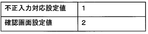
図13は、第3の実施形態に係るキー設定情報21の構成例について示した説明図である。
第3の実施形態の自動取引装置1では、キー設定情報21に、不正入力確認画面を表示するか否かを設定するためのパラメータ(以下、「確認画面設定値」と呼ぶ)が追加されている。確認画面設定値は、不正入力確認画面を表示しないことを示す「1」又は、不正入力確認画面を表示することを示す「2」のいずれかの値が設定可能であるものとする。なお、確認画面設定値の登録形式については限定されないものである。
なお、第2の実施形態の自動取引装置1においても、確認画面設定値に応じて不正入力確認画面を表示する構成としてもよい。
(C-2)第3の実施形態の動作
次に、以上のような構成を有する第3の実施形態の自動取引装置1の動作を説明する。
次に、以上のような構成を有する第3の実施形態の自動取引装置1の動作を説明する。
まず、ここでは、第3の実施形態の自動取引装置1において、キー設定情報21が設定される動作について図14を用いて説明する。
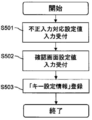
まず、自動取引装置1の係員操作部100において、オペレータからの操作を受付け、キー設定が選択されたものとする。これにより、制御部10(保守処理部12)は、キー設定を受付ける処理を開始し、係員操作部100に、不正入力対応設定値を受け付けるための不正入力対応設定値入力画面を表示させる(S501)。なお、ステップS501の処理(不正入力対応設定値入力画面の構成等)については、第1の実施形態(上述のステップS101の処理)と同様であるため詳しい説明は省略する。
次に、制御部10(保守処理部12)は、確認画面設定値を受付けるための操作画面(以下、「確認画面設定値入力画面」と呼ぶ)を係員操作部100に表示させる(S502)。
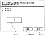
図15は、第3の実施形態における確認画面設定値入力画面の構成例について示した説明図である。
図15に示す確認画面設定値入力画面では、確認画面設定値(「1」又は「2」)の入力を受付けるためのフィールドF401と、フィールドF401に入力された確認画面設定値の確定を受け付ける確定キーB401と、確認画面設定値の入力を取消して前画面等(例えば、機能の選択メニュー等)に戻るための取消キーB402とが配置されている。ここでは、図15に示す確認画面設定値入力画面でフィールドF401に確認画面設定値が入力された後確定キーB401が押下されたものとする。
確認画面設定値入力画面で確定キーB401が押下されると、制御部10の保守処理部12は、入力された各値を(不正入力対応設定値、及び確認画面設定値)を、キー設定情報21に登録して登録し(S503)、処理を終了する。
以上のように、第3の実施形態の自動取引装置1では、キー設定情報21の内容が登録されるものとする。
次に、第3の実施形態の自動取引装置1が顧客と取引を行う際の処理の例について図16のフローチャートを用いて説明する。図16のフローチャートでは、第1の実施形態のフローチャート(上述の図7のフローチャート)と同様の処理を行うステップには同一のステップ番号(符号)を付している。以下では、第3の実施形態の自動取引装置1について第1の実施形態との差異部分のみを説明する。
第3の実施形態の自動取引装置1では、第1の実施形態において不正入力対応設定値が「1」だった場合に実行されるステップS212の前に、ステップS601、S602の処理が挿入されている点で第1の実施形態と異なっている。
第3の実施形態の制御部10(取引処理部11)は、上述のステップS211で、不正入力対応設定値が「1」だったと確認した場合、キー設定情報21の確認画面設定値を参照する(S601)。
制御部10(取引処理部11)は、キー設定情報21の確認画面設定値が「1」(不正入力確認画面を表示しない設定)に設定されている場合は、不正入力確認画面を表示させずにステップS212の処理に移行し、キー設定情報21の確認画面設定値が「2」(不正入力確認画面を表示する設定)に設定されている場合は、係員操作部100に不正入力確認画面を表示させる(S602)。
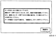
図17は、不正入力確認画面の構成例について示した説明図である。
図17に示す不正入力確認画面では、不正入力に関する情報を通知するためのメッセージ、及び顧客から確認を受付けるための確定キーB501が配置されている。不正入力確認画面で、確定キーB501が押下されると、制御部10(取引処理部11)は、次の処理(ステップS212の処理)に移行する。
図17に示すように、不正入力確認画面では、不正入力に関する情報を通知するためのメッセージとして「キーが反応しない状態になっています。複数のキーが押下されていないか、また、周囲の状態を確認してください。また、意図しないキーが押下された状態の場合は、その場からオペレータを呼び出してください。キーが問題なく反応する場合は、「確認済み」ボタンを押下してください」というメッセージが表示されている。以上のように、不正入力確認画面では、不正入力が発生している旨や、周囲の状態に問題がないか確認することを促す等のメッセージが含まれている。
(C-3)第3の実施形態の効果
第3実施形態によれば、第1の実施形態の効果に加えて以下のような効果を奏することができる。
第3実施形態によれば、第1の実施形態の効果に加えて以下のような効果を奏することができる。
第3の実施形態の自動取引装置1では、不正入力を検知した場合に、不正入力確認画面を表示している。これにより、第3の実施形態の自動取引装置1では、不正入力が発生していることを顧客に通知して確認させるため、顧客の取引の安全性を高めることができる。
(D)第4の実施形態
以下、本発明による取引装置の第4の実施形態を、図面を参照しながら詳述する。以下では、本発明の取引装置を自動取引装置に適用する例について説明する。
以下、本発明による取引装置の第4の実施形態を、図面を参照しながら詳述する。以下では、本発明の取引装置を自動取引装置に適用する例について説明する。
(D-1)第4の実施形態の構成
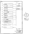
図18は、第4の実施形態に係る自動取引装置1の機能的構成について示したブロック図である。また、図19は、第4の実施形態に係る自動取引装置1の外観の斜視図である。
図18は、第4の実施形態に係る自動取引装置1の機能的構成について示したブロック図である。また、図19は、第4の実施形態に係る自動取引装置1の外観の斜視図である。
図18、図19に示すように、第4の実施形態の自動取引装置1では、フリッカ120(点滅可能なランプ)と、スピーカ130が追加されている点で第3の実施形態と異なっている。
図19に示すように、フリッカ120は、PINPAD部112の周辺に配置されており、点滅することで、例えば、顧客をPINPAD部112に注目させる等の機能を担っている。フリッカ120は、制御部10の制御に応じて点灯・点滅等の動作を行う。
また、図19に示すように、スピーカ130は、PINPAD部112の周辺に配置されており、音声出力(鳴動)することで、例えば、顧客をPINPAD部112に注目させる等の機能を担っている。制御部10(取引処理部11)は、例えば、警告音や警告メッセージ(例えば、不正入力に関する警告メッセージ)に応じた音声ファイル(例えば、WAV形式の音声ファイル(いわゆるWAVEファイル))に基づく音声をスピーカ130から出力させるようにしてもよい。
第4の実施形態の自動取引装置1では、不正入力の発生時(例えば、キーの二重押しや長押しの発生時)に、不正入力確認画面を表示する以外にも、他の出力処理の実行が可能な点で第3の実施形態とは異なっている。
具体的には、第4の実施形態の制御部10(取引処理部11)は、不正入力の発生時に、設定(例えば、キー設定情報21の設定)に応じて、スピーカ130からの警告音の鳴動、スピーカ130からの警告メッセージの鳴動、及びフリッカ120の点滅等が可能となっている。
図20は、第4の実施形態に係るキー設定情報21の構成例について示した説明図である。
第4の実施形態のキー設定情報21では、キー設定情報21に、スピーカ130からの警告音の鳴動をさせるか否かを設定するためのパラメータ(以下、「警告音設定値」と呼ぶ)が追加されている。警告音設定値は、警告音設定値を鳴動させないことを示す「1」又は、警告音を鳴動させることを示す「2」のいずれかの値が設定可能であるものとする。なお、警告音設定値の登録形式については限定されないものである。
また、第4の実施形態のキー設定情報21では、キー設定情報21に、スピーカ130からの警告メッセージの鳴動をさせるか否かを設定するためのパラメータ(以下、「警告メッセージ設定値」と呼ぶ)が追加されている。警告メッセージ設定値は、警告メッセージを鳴動させないことを示す「1」又は、警告メッセージを鳴動させることを示す「2」のいずれかの値が設定可能であるものとする。なお、警告メッセージ設定値の登録形式については限定されないものである。
さらに、第4の実施形態のキー設定情報21では、キー設定情報21に、フリッカ120の点滅をさせるか否かを設定するためのパラメータ(以下、「フリッカ設定値」と呼ぶ)が追加されている。フリッカ設定値は、フリッカ120を点滅させないことを示す「1」又は、フリッカ120を点滅させることを示す「2」のいずれかの値が設定可能であるものとする。なお、フリッカ設定値の登録形式については限定されないものである。
なお、第4の実施形態の自動取引装置1では、上述の通り、不正入力の発生時に、設定に応じて、不正入力確認画面の表示、スピーカ130からの警告音の鳴動、スピーカ130からの警告メッセージの鳴動、及びフリッカ120の点滅の4つの動作が可能となっているが、一部の動作だけを適用するようにしてもよいし、その他の動作と組み合わせて適用するようにしてもよい。
(D-2)第4の実施形態の動作
次に、以上のような構成を有する第4の実施形態の自動取引装置1の動作を説明する。
次に、以上のような構成を有する第4の実施形態の自動取引装置1の動作を説明する。
まず、ここでは、第4の実施形態の自動取引装置1において、キー設定情報21が設定される動作について図21を用いて説明する。
まず、自動取引装置1の係員操作部100において、オペレータからの操作を受付け、キー設定が選択されたものとする。これにより、制御部10(保守処理部12)は、キー設定を受付ける処理を開始し、係員操作部100に、不正入力対応設定値を受け付けるための不正入力対応設定値入力画面を表示させる(S701)。なお、ステップS701の処理(不正入力対応設定値入力画面の構成等)については、第1の実施形態(上述のステップS101の処理)と同様であるため詳しい説明は省略する。
次に、制御部10(保守処理部12)は、確認画面設定値を受付けるための確認画面設定値入力画面を係員操作部100に表示させて確認画面設定値の入力を受付ける(S702)。なお、確認画面設定値入力画面を係員操作部100に表示させて確認画面設定値の入力を受付ける処理については上述のステップS502と同様であるため詳しい説明を省略する。
次に、制御部10(保守処理部12)は、警告音設定値を受付けるための操作画面(以下、「警告音設定値入力画面」と呼ぶ)を係員操作部100に表示させて警告音設定値の入力を受付ける(S703)。
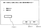
図22は、第4の実施形態における警告音設定値入力画面の構成例について示した説明図である。
図22に示す警告音設定値入力画面では、警告音設定値(「1」又は「2」)の入力を受付けるためのフィールドF501と、フィールドF501に入力された警告音設定値の確定を受け付ける確定キーB501と、警告音設定値の入力を取消して前画面等(例えば、機能の選択メニュー等)に戻るための取消キーB502とが配置されている。ここでは、図22に示す警告音設定値入力画面でフィールドF501に警告音設定値が入力された後確定キーB501が押下されたものとする。
次に、制御部10(保守処理部12)は、警告メッセージ設定値を受付けるための操作画面(以下、「警告メッセージ設定値入力画面」と呼ぶ)を係員操作部100に表示させて警告メッセージ設定値の入力を受付ける(S704)。
図23は、第4の実施形態における警告メッセージ設定値入力画面の構成例について示した説明図である。
図23に示す警告メッセージ設定値入力画面では、警告メッセージ設定値(「1」又は「2」)の入力を受付けるためのフィールドF601と、フィールドF601に入力された警告メッセージ設定値の確定を受け付ける確定キーB601と、警告メッセージ設定値の入力を取消して前画面等(例えば、機能の選択メニュー等)に戻るための取消キーB602とが配置されている。ここでは、図23に示す警告メッセージ設定値入力画面でフィールドF601に警告メッセージ設定値が入力された後確定キーB601が押下されたものとする。
次に、制御部10(保守処理部12)は、フリッカ設定値を受付けるための操作画面(以下、「フリッカ設定値入力画面」と呼ぶ)を係員操作部100に表示させてフリッカ設定値の入力を受付ける(S705)。
図24は、第4の実施形態におけるフリッカ設定値入力画面の構成例について示した説明図である。
図24に示すフリッカ設定値入力画面では、フリッカ設定値(「1」又は「2」)の入力を受付けるためのフィールドF701と、フィールドF701に入力されたフリッカ設定値の確定を受け付ける確定キーB701と、フリッカ設定値の入力を取消して前画面等(例えば、機能の選択メニュー等)に戻るための取消キーB702とが配置されている。ここでは、図24に示すフリッカ設定値入力画面でフィールドF701にフリッカ設定値が入力された後確定キーB701が押下されたものとする。
次に、制御部10の保守処理部12は、入力された各値(不正入力対応設定値、確認画面設定値、警告音設定値、警告メッセージ設定値、及びフリッカ設定値)を、キー設定情報21に登録して登録し(S706)、処理を終了する。
以上のように、第4の実施形態の自動取引装置1では、キー設定情報21の内容が登録されるものとする。
次に、第4の実施形態の自動取引装置1が顧客と取引を行う際の処理の例について図25、図26のフローチャートを用いて説明する。図25、図26のフローチャートでは、第3の実施形態のフローチャート(上述の図12のフローチャート)と同様の処理を行うステップには同一のステップ番号(符号)を付している。以下では、第4の実施形態の自動取引装置1について第3の実施形態との差異部分のみを説明する。
第4の実施形態の自動取引装置1では、第3の実施形態において不正入力対応設定値が「1」だった場合に実行されるステップS212、S601、S602の処理の後に、ステップS801~S806が挿入されている点で第3の実施形態と異なっている。以下では、図26に示す不正入力対応設定値が「1」だった場合に実行される処理(S601、S60、S801~S806)を中心に説明する。
第4の実施形態の制御部10(取引処理部11)は、上述のステップS211で、不正入力対応設定値が「1」だったと確認した場合、キー設定情報21の確認画面設定値を参照する(S601)。
制御部10(取引処理部11)は、キー設定情報21の確認画面設定値が「1」(不正入力確認画面を表示しない設定)に設定されている場合は、不正入力確認画面を表示させずに後述のステップS801の処理に移行し、キー設定情報21の確認画面設定値が「2」(不正入力確認画面を表示する設定)に設定されている場合は、係員操作部100に不正入力確認画面の表示を開始させ(S602)、後述するステップS801の処理に移行する。なお、不正入力確認画面については、上述の図17と同様であるため詳しい説明については省略する。
ステップS801に移行すると制御部10(取引処理部11)は、キー設定情報21の警告音設定値を参照する。
制御部10(取引処理部11)は、キー設定情報21の警告音設定値が「1」(警告音を鳴動させない設定)に設定されている場合は、警告音を鳴動させずに後述のステップS803の処理に移行し、キー設定情報21の警告音設定値が「2」(警告音を鳴動させる設定)に設定されている場合は、スピーカ130に警告音の鳴動を開始させ(S802)、後述するステップS803の処理に移行する。制御部10(取引処理部11)は、例えば、当該警告音に対応する音声ファイル(例えば、Waveファイル)に基づく音声をスピーカ130から出力させる。警告音の内容については限定されないものであるが、種々の警告音(例えば、種々のコンピュータ上でエラー表示を行う際に出力するアラーム音等)を適用することができる。
ステップS803に移行すると制御部10(取引処理部11)は、キー設定情報21の警告メッセージ設定値を参照する。
制御部10(取引処理部11)は、キー設定情報21の警告メッセージ設定値が「1」(警告メッセージを鳴動させない設定)に設定されている場合は、警告メッセージを鳴動させずに後述のステップS805の処理に移行し、キー設定情報21の警告メッセージ設定値が「2」(警告メッセージを鳴動させる設定)に設定されている場合は、スピーカ130に警告メッセージの鳴動を開始させ(S804)、後述するステップS805の処理に移行する。制御部10(取引処理部11)は、例えば、当該警告メッセージに対応する音声ファイル(例えば、Waveファイル)に基づく音声をスピーカ130から出力させる。警告メッセージの内容については限定されないものであるが、例えば、図17に示す確認画面に表示されるメッセージとしてもよい。
ステップS805に移行すると制御部10(取引処理部11)は、キー設定情報21のフリッカ設定値を参照する。
制御部10(取引処理部11)は、キー設定情報21のフリッカ設定値が「1」(フリッカ120を点滅させない設定)に設定されている場合は、フリッカ120を点滅させずにステップS212の処理に移行し、キー設定情報21のフリッカ設定値が「2」(フリッカ120を点滅させる設定)に設定されている場合は、フリッカ120の点滅を開始させ(S806)、ステップS212の処理に移行する。
ステップS212に移行すると、制御部10(取引処理部11)は、不正入力が解除されるまで(例えば、二重押しの状態や長押しの状態が解除されるまでの期間)何もせずに待機し、不正入力が解除された後にステップS207に移行する。なお、不正入力が解除された場合、制御部10(取引処理部11)は、不正入力に伴って実行した各動作(不正入力確認画面の表示、警告音の鳴動、警告メッセージの鳴動、及びフリッカ120の点滅)について停止してからステップS207に移行するようにしてもよい。
(D-3)第4の実施形態の効果
第4実施形態によれば、第3の実施形態の効果に加えて以下のような効果を奏することができる。
第4実施形態によれば、第3の実施形態の効果に加えて以下のような効果を奏することができる。
第4の実施形態の自動取引装置1では、不正入力の発生時に、設定に応じて、不正入力確認画面以外の種々の動作(スピーカ130からの警告音の鳴動、スピーカ130からの警告メッセージの鳴動、及びフリッカ120の点滅)にも対応している。これにより、第4の実施形態の自動取引装置1では、第3の実施形態と比較して、不正入力が発生していることを、より確実に顧客に認識させ、不正な支払い取引の低減が期待できる。
また、第4の実施形態の自動取引装置1では、キー設定情報21の設定内容に応じて、不正入力の発生時に行う動作を柔軟に設定可能とすることで、利便性を向上させている。
さらに、第4の実施形態の自動取引装置では、不正入力の発生時に、フリッカ120やスピーカ130による出力を行うので、周囲に注意を促す事ができ、不正な支払い取引の低減が期待できる。
(E)他の実施形態
本発明は、上記の各実施形態に限定されるものではなく、以下に例示するような変形実施形態も挙げることができる。
本発明は、上記の各実施形態に限定されるものではなく、以下に例示するような変形実施形態も挙げることができる。
(E-1)上記の各実施形態の自動取引装置1では、ソフトウェアキーを含む操作画面を表示可能な表示操作部30と、ハードウェアキーにより構成されたキー入力操作部110を含む構成により、顧客からの入力を受付ける入力部が構成されているが、キー入力操作部110を省略して全てキーをソフトウェアキーで入力部を構成するようにしてもよい。
例えば、図27に示す自動取引装置1Aでは、キー入力操作部110(ファンクションキー部111及びPINPAD部112)が省略されている。自動取引装置1Aでは、その代わりに、表示操作部30のサイズを大きくし、図28に示すように、省略したハードウェアキーを全てソフトウェアキーとして表示可能とするようにしてもよい。図28に示す表示操作部30では、操作画面を表示するための領域31の周囲に、ソフトウェアキーで構成された8つのファンクションキー31-1~32-8や、ソフトウェアキーで構成されたPINPAD33が配置されている。自動取引装置1Aの制御部10(取引処理部11)では、表示操作部30上に配置されたソフトウェアキーについて長押し状態や二重押し状態を検知することができる。
(E-2)上記の各実施形態では本発明の取引装置を自動取引装置(ATM)に適用する例について説明したが、本発明の取引装置は自動販売機や自動券売機等その他の装置に適用することもできる。
(E-3)上記の各実施形態では、制御部10(取引処理部11)は、長押し状態及び二重押し状態の両方を監視しているかいずれか一方のみを監視するようにしてもよい。
日本出願特願2015-146959号の開示はその全体が参照により本明細書に取り込まれる。
本明細書に記載された全ての文献、特許出願、および技術規格は、個々の文献、特許出願、および技術規格が参照により取り込まれることが具体的かつ個々に記された場合と同程度に、本明細書中に参照により取り込まれる
1…自動取引装置、10…制御部、11…取引処理部、12…保守処理部、20…データ記録部、30…表示操作部、40…カード処理部、401…カード挿入排出口、50…紙幣入出金部、501…紙幣入出金口、60…硬貨入出金部、601…硬貨入出金口、70…ジャーナル記録部、80…通帳処理部、801…通帳挿入排出口、90…明細票発行部、901…明細票排出口、100…係員操作部、110…キー入力操作部、111…ファンクションキー部、112…PINPAD部。
Claims (9)
- 複数のキーを備える入力部と、
少なくとも複数の上記キーが同時に押下された二重押し状態、又はいずれかの上記キーが所定時間以上継続して押下された長押し状態のいずれか一方を監視し、二重押し状態又は長押し状態のいずれかを検知した場合に不正入力が行われたと判断する判断手段と、
上記判断手段で、不正入力が行われたと判断された場合の処理内容を示す設定情報を記録する記録部と、
上記入力部を用いて顧客との取引処理を行うものであって、上記判断手段で、不正入力が行われたと判断された場合に、上記記録部で記録された設定情報に従った動作を行う取引処理手段と、
を有する取引装置。 - 上記記録部の設定情報の変更を受付ける設定変更手段をさらに有する請求項1に記載の取引装置。
- 上記設定情報には、上記判断手段で、不正入力が行われたと判断された場合の処理内容に対応する不正入力対応設定値が設定されている請求項1に記載の取引装置。
- 上記設定情報には、上記判断手段で、不正入力が行われたと判断された場合の処理内容に対応する不正入力対応設定値と、当該不正入力対応設定値を適用する期間との組み合わせが設定されている請求項1に記載の取引装置。
- 不正入力対応設定値は、上記入力部の上記キーを用いた入力を無効とする第1の動作、受付中の取引を終了する第2の動作、又は障害が発生したものとして取引の受付けを停止する第3の動作のいずれかの動作に対応する値である請求項3又は4に記載の取引装置。
- 顧客に取引に関する情報を表示する表示部をさらに備え、
上記取引処理手段は、上記判断手段で不正入力が行われたと判断された場合に、上記表示部に不正入力に関する確認を促す情報を出力させる
請求項1に記載の取引装置。 - スピーカをさらに備え、
上記取引処理手段は、上記判断手段で不正入力が行われたと判断された場合に、上記スピーカから警告音を出力させる
請求項1に記載の取引装置。 - スピーカをさらに備え、
上記取引処理手段は、上記判断手段で不正入力が行われたと判断された場合に、上記スピーカから、不正入力に関する警告メッセージの音声を出力させる
請求項1に記載の取引装置。 - フリッカをさらに備え、
上記取引処理手段は、上記判断手段で不正入力が行われたと判断された場合に、上記フリッカを点滅させる
請求項1に記載の取引装置。
Priority Applications (3)
| Application Number | Priority Date | Filing Date | Title |
|---|---|---|---|
| RU2017143783A RU2667577C1 (ru) | 2015-07-24 | 2016-06-16 | Устройство транзакций |
| US15/738,571 US20180190061A1 (en) | 2015-07-24 | 2016-06-16 | Transaction device |
| CN201680033876.3A CN107636736B (zh) | 2015-07-24 | 2016-06-16 | 交易装置 |
Applications Claiming Priority (2)
| Application Number | Priority Date | Filing Date | Title |
|---|---|---|---|
| JP2015146959A JP6554969B2 (ja) | 2015-07-24 | 2015-07-24 | 取引装置 |
| JP2015-146959 | 2015-07-24 |
Publications (1)
| Publication Number | Publication Date |
|---|---|
| WO2017018089A1 true WO2017018089A1 (ja) | 2017-02-02 |
Family
ID=57884342
Family Applications (1)
| Application Number | Title | Priority Date | Filing Date |
|---|---|---|---|
| PCT/JP2016/068006 Ceased WO2017018089A1 (ja) | 2015-07-24 | 2016-06-16 | 取引装置 |
Country Status (5)
| Country | Link |
|---|---|
| US (1) | US20180190061A1 (ja) |
| JP (1) | JP6554969B2 (ja) |
| CN (1) | CN107636736B (ja) |
| RU (1) | RU2667577C1 (ja) |
| WO (1) | WO2017018089A1 (ja) |
Citations (2)
| Publication number | Priority date | Publication date | Assignee | Title |
|---|---|---|---|---|
| JPH05265632A (ja) * | 1992-03-18 | 1993-10-15 | Gunze Ltd | タッチパネル装置 |
| JP2010282309A (ja) * | 2009-06-03 | 2010-12-16 | Hitachi Omron Terminal Solutions Corp | 自動取引装置 |
Family Cites Families (20)
| Publication number | Priority date | Publication date | Assignee | Title |
|---|---|---|---|---|
| GB2304958B (en) * | 1995-09-07 | 1999-10-27 | Mars Inc | Method and apparatus for protecting a money-handling unit vunerable to liquid |
| JP3455969B2 (ja) * | 1995-11-06 | 2003-10-14 | 沖電気工業株式会社 | 自動取引システム |
| JP2000339515A (ja) * | 1999-05-26 | 2000-12-08 | Nec Yonezawa Ltd | Atm装置およびatm入力方法 |
| AU2001234908A1 (en) * | 2000-02-11 | 2001-08-20 | Marcio Marc Abreu | System and method for communicating product recall information, product warningsor other product-related information to users of products |
| US6732278B2 (en) * | 2001-02-12 | 2004-05-04 | Baird, Iii Leemon C. | Apparatus and method for authenticating access to a network resource |
| JP2005149473A (ja) * | 2003-10-20 | 2005-06-09 | Keiichi Kato | 障害者年配者入力支援システム |
| US20050167487A1 (en) * | 2004-02-02 | 2005-08-04 | Conlon Jennifer L. | System and method for customizing designs for credit cards, ATM/debit cards, checks, gift cards, and membership cards |
| US7453376B2 (en) * | 2004-09-09 | 2008-11-18 | Hewlett-Packard Development Company, L.P. | Method, apparatus, and computer-readable medium for key press determination |
| KR100997911B1 (ko) * | 2005-05-19 | 2010-12-02 | 샌디스크 아이엘 엘티디 | 개인의 존재를 조건으로 하는 토큰에 의한 거래 인증 |
| JP4935475B2 (ja) * | 2007-04-13 | 2012-05-23 | 沖電気工業株式会社 | 入力装置 |
| KR101445196B1 (ko) * | 2007-11-23 | 2014-09-29 | 삼성전자주식회사 | 터치 스크린을 가지는 휴대 단말기의 문자 입력 방법 및장치 |
| CN101403264B (zh) * | 2008-09-19 | 2012-08-29 | 刘海君 | 电子密码控制电路 |
| US8961619B2 (en) * | 2009-01-06 | 2015-02-24 | Qualcomm Incorporated | Location-based system permissions and adjustments at an electronic device |
| US20140201087A1 (en) * | 2011-08-10 | 2014-07-17 | Nautilus Hyosung Inc. | Touch screen having integrated epp, and input information processing method for automated teller machine using same |
| RU2507588C2 (ru) * | 2012-03-20 | 2014-02-20 | Владимир Алексеевич Небольсин | Способ повышения безопасности автоматизированной платежной системы |
| JP6106954B2 (ja) * | 2012-05-30 | 2017-04-05 | 沖電気工業株式会社 | 情報処理装置、操作者識別システム、方法、及びプログラム |
| JP5841023B2 (ja) * | 2012-08-27 | 2016-01-06 | 株式会社ソニー・コンピュータエンタテインメント | 情報処理装置、情報処理方法、プログラム及び情報記憶媒体 |
| JP6022988B2 (ja) * | 2013-04-11 | 2016-11-09 | 富士通フロンテック株式会社 | 自動取引装置、自動取引装置の操作誘導方法および自動取引装置の操作誘導プログラム |
| JP5988914B2 (ja) * | 2013-05-15 | 2016-09-07 | 日立オムロンターミナルソリューションズ株式会社 | 自動取引装置及び自動取引方法 |
| US9747734B2 (en) * | 2014-12-12 | 2017-08-29 | International Busines Machines Corporation | Authentication of users with tremors |
-
2015
- 2015-07-24 JP JP2015146959A patent/JP6554969B2/ja active Active
-
2016
- 2016-06-16 CN CN201680033876.3A patent/CN107636736B/zh active Active
- 2016-06-16 US US15/738,571 patent/US20180190061A1/en not_active Abandoned
- 2016-06-16 WO PCT/JP2016/068006 patent/WO2017018089A1/ja not_active Ceased
- 2016-06-16 RU RU2017143783A patent/RU2667577C1/ru active
Patent Citations (2)
| Publication number | Priority date | Publication date | Assignee | Title |
|---|---|---|---|---|
| JPH05265632A (ja) * | 1992-03-18 | 1993-10-15 | Gunze Ltd | タッチパネル装置 |
| JP2010282309A (ja) * | 2009-06-03 | 2010-12-16 | Hitachi Omron Terminal Solutions Corp | 自動取引装置 |
Also Published As
| Publication number | Publication date |
|---|---|
| JP2017027457A (ja) | 2017-02-02 |
| CN107636736B (zh) | 2019-05-10 |
| RU2667577C1 (ru) | 2018-09-21 |
| JP6554969B2 (ja) | 2019-08-07 |
| US20180190061A1 (en) | 2018-07-05 |
| CN107636736A (zh) | 2018-01-26 |
Similar Documents
| Publication | Publication Date | Title |
|---|---|---|
| JP4844530B2 (ja) | 取引監視システム | |
| KR101120868B1 (ko) | 금융자동화기기용 입력 장치 및 금융자동화기기용 입력 장치 동작 방법 | |
| JP6554969B2 (ja) | 取引装置 | |
| JP5544754B2 (ja) | 自動取引装置 | |
| JP6569316B2 (ja) | 取引装置 | |
| JP6379760B2 (ja) | 自動取引装置 | |
| KR100966677B1 (ko) | 금융 자동화기기의 진위 판별 시스템 및 진위 판별 방법 | |
| CN101488259A (zh) | 交易处理装置 | |
| JP4727305B2 (ja) | 自動取引装置 | |
| JP2010079754A (ja) | 通報装置 | |
| JP2014021784A (ja) | 取引装置及びプログラム | |
| JP7541794B2 (ja) | 貨幣処理装置、貨幣処理装置の異常解消方法およびコンピュータプログラム | |
| JPH11203539A (ja) | 自動取引装置 | |
| JP2008047063A (ja) | 自動取引装置 | |
| JP6561561B2 (ja) | 自動取引装置 | |
| JP5712831B2 (ja) | 自動取引装置 | |
| JP5022126B2 (ja) | 現金自動取引装置 | |
| JP6152766B2 (ja) | 取引装置及び取引方法 | |
| JP2017146701A (ja) | 自動取引装置 | |
| JPH05266305A (ja) | 自動取引装置における取引制限内容の事前通知方法 | |
| KR101965840B1 (ko) | 금융 자동화 기기 | |
| JP2017151848A (ja) | 自動取引装置 | |
| JP6756117B2 (ja) | 現金処理装置 | |
| JP5986936B2 (ja) | 自動取引装置および取引方法 | |
| JP6565137B2 (ja) | 自動取引装置 |
Legal Events
| Date | Code | Title | Description |
|---|---|---|---|
| 121 | Ep: the epo has been informed by wipo that ep was designated in this application |
Ref document number: 16830194 Country of ref document: EP Kind code of ref document: A1 |
|
| WWE | Wipo information: entry into national phase |
Ref document number: 2017143783 Country of ref document: RU |
|
| NENP | Non-entry into the national phase |
Ref country code: DE |
|
| 122 | Ep: pct application non-entry in european phase |
Ref document number: 16830194 Country of ref document: EP Kind code of ref document: A1 |