WO2017010478A1 - 運転状態監視方法,装置,およびそれを備えた車両 - Google Patents
運転状態監視方法,装置,およびそれを備えた車両 Download PDFInfo
- Publication number
- WO2017010478A1 WO2017010478A1 PCT/JP2016/070536 JP2016070536W WO2017010478A1 WO 2017010478 A1 WO2017010478 A1 WO 2017010478A1 JP 2016070536 W JP2016070536 W JP 2016070536W WO 2017010478 A1 WO2017010478 A1 WO 2017010478A1
- Authority
- WO
- WIPO (PCT)
- Prior art keywords
- driver
- driving
- visual
- monitoring device
- visual confirmation
- Prior art date
- Legal status (The legal status is an assumption and is not a legal conclusion. Google has not performed a legal analysis and makes no representation as to the accuracy of the status listed.)
- Ceased
Links
Images



Classifications
-
- B—PERFORMING OPERATIONS; TRANSPORTING
- B60—VEHICLES IN GENERAL
- B60W—CONJOINT CONTROL OF VEHICLE SUB-UNITS OF DIFFERENT TYPE OR DIFFERENT FUNCTION; CONTROL SYSTEMS SPECIALLY ADAPTED FOR HYBRID VEHICLES; ROAD VEHICLE DRIVE CONTROL SYSTEMS FOR PURPOSES NOT RELATED TO THE CONTROL OF A PARTICULAR SUB-UNIT
- B60W40/00—Estimation or calculation of non-directly measurable driving parameters for road vehicle drive control systems not related to the control of a particular sub unit, e.g. by using mathematical models
- B60W40/08—Estimation or calculation of non-directly measurable driving parameters for road vehicle drive control systems not related to the control of a particular sub unit, e.g. by using mathematical models related to drivers or passengers
-
- G—PHYSICS
- G08—SIGNALLING
- G08G—TRAFFIC CONTROL SYSTEMS
- G08G1/00—Traffic control systems for road vehicles
- G08G1/16—Anti-collision systems
Definitions
- the present invention relates to a technique for monitoring a driver's state monitoring and keeping the driver in an appropriate driving state in a vehicle equipped with a travel control device that supports the driving operation of the driver.
- the sovereignty of driving operations is the control system.
- it is determined that it is difficult to continue automatic driving it is required that the driver's sovereignty be appropriately switched to the driver.
- Patent Document 1 during driving support control execution, the support level is lowered by intentionally reducing the control amount and the assist amount at predetermined time intervals, and the driver's reaction to it is confirmed.
- a method for determining the driving state of the driver is described.
- Patent Document 2 also confirms whether or not the driver can properly drive when switching is requested from the driver by a switch operation or the like. Describes how to perform processing such as rejecting a request.
- Patent Document 1 is applicable to a system in which the driver has the sovereignty of driving even when driving assistance is being executed, and the driver assumes responsibility for pedal operation and steering operation.
- Patent Document 2 determines whether or not driving switching is possible in response to a driver switching request, but does not describe a method for monitoring the driver state during automatic driving.
- the object of the present invention is to solve the above-mentioned problems.
- the driver's condition during automatic driving is monitored, the time required to switch the driving sovereignty to the driver is estimated, and the driver is automatically It is an object of the present invention to provide a driver state monitoring method and apparatus for maintaining an appropriate driving state corresponding to driving.
- a driving support control device that supports a driver's driving operation is used in a vehicle having an object detection means for detecting an object around the vehicle and a driver state detection means for detecting a driver's state.
- the driving state monitoring device that monitors the driving state of the driver inside
- a visual object determining means for determining a candidate for an object for instructing the driver to perform visual confirmation
- a visual confirmation instruction means for requesting the driver to visually observe the object determined by the visual object determining means at predetermined time intervals
- the visual confirmation determination means for determining that the driver has viewed at least one of the objects determined by the visual object determination means, and the visual confirmation instructing means instruct the driver to perform visual confirmation. It is possible to solve the problem by a driver state monitoring method and apparatus, and a vehicle equipped with the same, including a confirmation time measuring means for measuring the time until it is detected by the visual confirmation determination means that the driver visually confirms .
- the driver's sovereignty can be granted according to the system requirements during the advanced driving support control such as automatic driving.
- the driver can switch the driving safely and quickly.
- the object detection means 10 is installed outside the passenger compartment, detects a moving object such as a person around the own vehicle, a moving object such as a vehicle, a stationary object such as a sign, a signal, and a building and recognizes the object.
- a moving object such as a person around the own vehicle
- a moving object such as a vehicle
- a stationary object such as a sign, a signal
- a building and recognizes the object.
- the relative positional relationship between the object and the object detection means 10 and the type and attribute of the object are output.
- dynamic object information for example, the relative positional relationship between the vehicle and the object can be grasped by sensors such as the stereo camera 11, the monocular camera 12, and the radar 13.
- a sensor using image processing is used to recognize the type and attribute of the detected object.
- a GPS 15 Global Positioning System
- map information 14 are combined and the driver can visually check at the current position. Feature candidates may be extracted.
- the driving state detection means 20 is installed toward the driver in the passenger compartment, and detects the driver's line of sight and sitting posture as the driver's state.
- the driver camera 21 performs image processing on video information from the camera directed at the driver, detects the driver's line of sight based on the driver's face and eye orientation, and detects the line of sight from the driver's head position. Output direction (vector).
- the seating posture sensor 22 measures the driver's seating state with a plurality of weighted sensors, and estimates the driver's seating posture from the load distribution.
- the driver camera 21 detects the posture of the upper body of the driver from the video in addition to the detection of the line of sight, and combines the output with the load distribution of the seating posture sensor 22 to estimate the current driving posture. It is preferable that the driving state detection means 20 outputs a comparison result with the driving posture.
- the driver state monitoring device 30 secures an appropriate time and switches from automatic control to driver operation when it becomes necessary to switch the driver's sovereignty during advanced driving support control such as automatic driving.
- advanced driving support control such as automatic driving.
- the time required for driving switching is measured or estimated in advance and output to the driving support control device.
- the method for measuring the time required for switching driving requires that the information (pedestrians, vehicles, signs, etc.) outside the vehicle required for driving be checked visually when driving is switched to the driver.
- the time from the state where the information outside the passenger compartment is not visually observed to the state where it is visually observed is measured as the time required for switching. Details will be described with reference to the flowchart of FIG.
- the driver state monitoring device 30 includes a visual object determination unit 31, a visual confirmation instruction unit 32, a visual confirmation determination unit 33, and a confirmation time measurement unit 34. .
- the visual object determining means 31 recognizes when driving is performed when the driving sovereignty is switched in the driving environment based on the relative positional relationship, type, attribute, etc. with the object output by the object detecting means 10. At least one object information outside the vehicle compartment is selected, and for example, identification information (target ID, etc.) is output.
- the visual confirmation instructing means 32 outputs a command to the notification means 40 in order to request the driver to confirm the visual object based on the output of the visual object determining means 31.
- the visual confirmation determination means 33 determines whether or not the driver has viewed the object set by the visual object determination means 31 based on the outputs of the driving state detection means 20 and the visual object determination means 31.
- the confirmation time measuring means 34 is a period from when the visual confirmation instructing means 32 commands the notifying means 40 to start a visual confirmation request to the driver until the driver visually confirms the object by the visual confirmation determining means 33. Measure the time and use this time as the time required for switching the driving sovereignty.
- the notification means 40 is composed of a display device 41, a speaker 42, a seat belt actuator 43, and the like. Based on the output of the driver state monitoring device 30, a request for visual confirmation is given to the driver by display, voice, and bodily sensation (vibration). Tell.
- the driving support control device 50 includes an actuator 55 (braking device 56, steering device 57, driving device 58) based on other control devices and sensor information mounted on the vehicle and the output of the driver state monitoring device 30.
- a control signal is output to the vehicle to control the running of the vehicle.
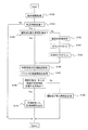
- S100 object information around the vehicle is acquired. Thereafter, in S101, it is determined whether or not a predetermined time has elapsed since the previous operation switching time measurement. If a negative determination is made, the process is temporarily interrupted. If a positive determination is made, the process proceeds to S102.
- S102 it is determined whether or not the time required for operation switching is being measured. If it is already in the measurement state, an affirmative determination is made and S106 is executed. If a negative determination is made, it is a state before the start of measurement, and initialization is performed in S103 to S105.
- S103 an object to be visually checked is determined based on the object information around the vehicle acquired in S100.
- step S104 a time measurement counter is initialized. Further, in S105, a flag indicating that the operation switching time is being measured is set, and the process proceeds to S106.
- the driver is requested to visually confirm the target object determined in S103.
- This process is performed by a method that reduces the annoyance to the driver, for example, by providing guidance every predetermined time when notifying by voice or the like, and continuously displaying when using a display device or the like.
- the driver's line-of-sight information is acquired in S107.
- the driver's line-of-sight information is information related to the driver's line of sight among the outputs of the driving state detection means 20.
- the driver's line-of-sight information acquired in S107 is compared with the position information of the confirmation target object determined in S103 out of the object information around the vehicle acquired in S100, and the driver visually checks the confirmation target object. Determine whether or not. If a negative determination is made here, the driver has not responded to the visual confirmation request for the object, so the time measurement is continued in S109. On the other hand, when an affirmative determination is made in S108, the time measurement is terminated and output to the driving support control device 50 as the time required for switching the driving sovereignty.
- the driver state monitoring device 30 is used when the driving sovereignty is switched to the driver in view of the fact that the driver's driving consciousness is lower than the normal state during the driving support control.
- the required switching time that is, the time until the driver's driving consciousness returns to the normal state, maintaining the driver's driving state (driving consciousness) in an appropriate state.
- FIGS. 3 and 4 are diagrams schematically showing the process of the configuration of FIG. 1 and the flowchart of FIG. 2 in a specific scene.
- the object detection unit 11 is a stereo camera 11, and the driving state detection unit is a driver camera 21.
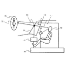
- This is an example of a head-up display that can superimpose and display information to be given to the driver as the display device 41 of the notification means 40 on the windshield 71 on the driver's line of sight.
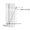
- FIG. 3 a scene where a pedestrian crossing and a pedestrian 72 are present in front of the host vehicle is automatically driven by driving support control. If the predetermined time has elapsed in S101 in the scene and measurement of the operation switching time is started, first, as object information obtained in S100, the target ID and the relative positional relationship with the host vehicle (x, y ), An object to be visually confirmed is determined based on the moving direction and type (S103). In FIG. 3, since there is one object, the pedestrian 72 is determined as the target. Then, initialization of the counter and a flag are set, and a visual confirmation is requested from the driver (S106).
- the driver camera 21 calculates the sitting posture and line of sight from the position of the driver's head 70 and upper body, but at the same time, when the driver is properly seated from the position of the seat and the time series information output by the driver camera 21.
- a head position (referred to as a reference head position) is calculated.
- the line of sight at the reference head position (referred to as the reference line of sight L1) is calculated from the position information of the visual confirmation target determined based on the reference head position and the output of the stereo camera 11.
- a point P1 where the reference line of sight L1 and the windshield 71 intersect is a position where a marker or the like is displayed as a request for visual confirmation. The marker is superimposed and displayed as if the marker 73 is attached to the actual pedestrian 72 when the marker is viewed from the reference head position.
- the driver's head position is greatly deviated from the reference head position when the driver confirms the visual confirmation in S106 with respect to the marker displayed in this way, If the posture is taken and visual confirmation is not performed at a position close to the reference head position, the line of sight does not coincide with the reference line of sight in S107, and measurement is continued for the time required for operation switching.
- the driving switching time is measured including the return of the driving posture to an appropriate position as described above. If the driving consciousness is reduced or the posture is not appropriate during automatic driving, Measurements are taken including the time to return, and the operation switching time can be measured more accurately.
- time required for switching is preferably equal to or shorter than a predetermined time, and may be configured as shown in the flowchart of FIG.
- the system may request switching to manual driving.
- the driving state monitoring device 30 needs to maintain the driver's driving consciousness and sitting posture so that the driving switching time becomes a predetermined time or less, together with the estimation of the time required for switching. Therefore, when the operation switching time is estimated to be equal to or longer than the predetermined time, the driving state monitoring device 30 interrupts the measurement of the time required for switching in S201, and the notification means 40 and the driving support control device 50 in S202. In response to this, a signal indicating that no response from the driver is obtained is output. Based on this signal, a warning is issued by the notification means 40, or the control content of the driving support control device 50 is switched to processing when the driver is not ready for driving switching.
- warning processing in S202 include not only warning by sound from the speaker 42 but also warning.
- the seat belt actuator 43 that winds up the seat belt may be commanded to directly apply vibration to the driver.
- the vehicle automatically follows the vehicle (preceding vehicle) traveling in front of the host vehicle until it stops and confirms the safety of the shoulder when the preceding vehicle stops. On the other hand, if the vehicle stops on the shoulder or there is no preceding vehicle, the safety is confirmed and the vehicle is automatically controlled to stop on the shoulder.
- FIG. 7 shows a processing procedure in which S301 and S302 are added to the flowchart of FIG.
- the visual target is determined in S103 based on the object information acquired in S100.
- the flowchart of FIG. 7 when a visual object is determined when there are a plurality of objects acquired in S100, the importance in the driving environment is calculated and the visual object is selectively determined.
- S301 and S302 are the same as those in FIG.
- S301 information related to the driving environment is acquired. This information is acquired based on map information regarding the number of lanes, presence / absence of pedestrian crossings, road shape (straight line, curve), presence / absence of signals and signs and their positions, for example. Considering this information, the object information in S100, the vehicle position, the traveling direction, and the speed, the importance is set in S302.
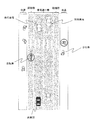
- the importance level is set for bicycles that run along the lane in which the vehicle travels and pedestrians who want to cross a pedestrian crossing (both marked with a circle). This is a target that requires attention when the vehicle travels, and the importance is set high for such objects. If there are many objects of the same type (pedestrians in FIG. 8), they are handled as one set, and in S106, a visual confirmation such as “Please confirm pedestrians” is made as a voice. You may request. In this case, when it is confirmed that the driver's line of sight is directed to any of the plurality of detected pedestrians, an affirmative determination is made in S108, and the measurement of the driving switching time is ended.
- Object detection means 11 Stereo camera 12: Monocular camera 13: Radar 14: Map 15: GPS 20: Driver status detection means 21: Driver camera 30: Driver condition monitoring device 31: Visual object determination means 32: Visual confirmation instruction means 33: Visual confirmation judgment means 34: Confirmation time measurement means 40: Notification method 41: Head-up display 42: Speaker 43: Seat belt actuator 50: Driving support control device 51: Windshield 55: Actuator 56: Braking device 57: Steering device 58: Drive unit 70: Driver 71: Windshield 72: Confirmation target (pedestrian) 73: Marker
Landscapes
- Engineering & Computer Science (AREA)
- Physics & Mathematics (AREA)
- Automation & Control Theory (AREA)
- Mathematical Physics (AREA)
- Transportation (AREA)
- Mechanical Engineering (AREA)
- General Physics & Mathematics (AREA)
- Traffic Control Systems (AREA)
- Control Of Driving Devices And Active Controlling Of Vehicle (AREA)
Abstract
運転者の違和感や不安感を抑え,適切な走行支援を行うことが可能な車両用走行支援装置を提供すること。 運転者の運転操作を支援する運転支援制御装置を備え,車両周辺の物体を検出する物体検出手段と運転者の視線を検出する視線検出手段と を備えた車両に用いられ,運転支援制御中の運転者の運転状態を監視する運転状態監視装置において, 運転者に目視確認を指示する物体の候補を決定する目視対象物決定手段と 前記目視対象物決定手段で決定した対象物を所定時間毎に目視することを運転者に要求する目視確認指示手段と 前記目視対象物決定手段が決定した対象物のうち少なくとも一つを運転者が目視したことを判定する目視確認判定手段と 前記目視確認指示手段が運転者に対して目視確認を指示してから前記目視確認判定手段により運転者が目視確認したことを検出するまでの時間を計測する確認時間計測手段と を備える。
Description
本発明は,運転者の運転操作を支援する走行制御装置を備えた車両において,運転者の状態監視を監視し,運転者を適切な運転状態に保つ技術に関する。
運転者の運転負荷を軽減するため,車間距離に応じて速度制御を行ったりレーンマーカに沿って操舵制御を行ったりするシステムが知られているが,これらのシステムは,運転者の姿勢や覚醒度等が適切な状態である必要があり,運転者の運転状態を監視する方法や適切な状態に保つ方法が提案されている。
また,米国運輸省の道路交通安全局によれば,より高度な運転支援システム(例えば,自動運転システム)においては,運転操作の主権が制御システムになるが,その場合であっても,システムの判断により自動運転を継続することが困難であると判断した場合に,運転主権を適切に運転者に切り替えられることを求めている。
これに対して,例えば,特許文献1には,運転支援制御実行中において,所定時間毎に制御量やアシスト量など意図的に下げることで支援レベルを下げ,それに対する運転者の反応を確認することで,運転者の運転状態を判定する方法が記載されている。
また,特許文献2には,スイッチ操作などにより運転者から運転切り替えが要求された場合に,運転者が適切に運転できるか否かを確認し,その結果により運転切り替えを行ったり,運転切り替えの要求を却下するなどの処理を行う方法が記載されている。
上記従来技術(特許文献1)は,運転支援の実行中であっても運転の主権が運転者にあり,ペダル操作やステアリング操作の責任が運転者を前提としたシステムには適用可能であるが,より高度な運転支援状態(例えば,自動運転中)においては,運転の主権がシステムにあり運転者の運転操作への関わりを検出しにくくなるため,運転者の運転状態を適切に判断できない場合がある。また,特許文献2では,運転者の切り替え要求に対して,運転切り替えが可能か否かの判断を行っているが,自動運転中における運転者の状態を監視する方法は記載されていない。
上記従来技術で述べたように,自動運転を解除し運転者に主権が切り替わる場合があり,自動運転中であっても,運転者は自動運転に対応した運転状態を維持する必要がある。
本発明の目的は,上記課題を解決するためのものであり, 自動運転中における運転者の状態を監視し,運転主権を運転者に切り替えるために必要な時間を推定するとともに,運転者を自動運転に対応した適切な運転状態に維持する運転者の状態監視方法および装置を提供することにある。
上記課題は,
運転者の運転操作を支援する運転支援制御装置を備え,車両周辺の物体を検出する物体検出手段と運転者の状態を検出する運転者状態検出手段と
を備えた車両に用いられ,運転支援制御中の運転者の運転状態を監視する運転状態監視装置において,
運転者に目視確認を指示する物体の候補を決定する目視対象物決定手段と
前記目視対象物決定手段で決定した対象物を所定時間毎に目視することを運転者に要求する目視確認指示手段と
前記目視対象物決定手段が決定した対象物のうち少なくとも一つを運転者が目視したことを判定する目視確認判定手段と
前記目視確認指示手段が運転者に対して目視確認を指示してから前記目視確認判定手段により運転者が目視確認したことを検出するまでの時間を計測する確認時間計測手段と
を有すること
を特徴とする運転者の状態監視方法,装置およびそれを備えた車両により解決できる。
運転支援制御中の運転者の状態を適切に把握するとともに,運転者の運転状態を所定の状態に維持することで,自動運転のような高度な運転支援制御中にシステムの要求により運転主権を切り替える必要が生じた場合に,安全かつ速やかに運転者に運転を切り替えられる。
以下,本発明の実施形態を図面に基づいて詳細に説明する。
本発明における第1の実施形態について,図を用いて説明する。
図1において,物体検出手段10は,車室外に向けて設置され,自車両周辺の人,車両などの移動物体や標識,信号,建物などの静止物体を検出するとともにその物体を認識し,認識した結果,その物体と物体検出手段10との相対的な位置関係およびその物体の種別,属性を出力する。動的な物体の情報に関しては,例えば,ステレオカメラ11,単眼カメラ12,レーダ13などのセンサにより車両と物体との相対的な位置関係を把握することができる。好ましくは,検知した物体の種別や属性を認識するために画像処理を活用したセンサを用いると良い。また,静止物体を認識するためには,画像処理を活用したセンサの他,GPS15(Global Positioning System:全地球測位システム)と地図情報14とを組み合わせて,現在の位置において運転者が目視可能な地物の候補を抽出してもよい。
運転状態検出手段20は,車室内の運転者に向けて設置され,運転者の状態として,運転者の視線や着座姿勢を検出する。ドライバカメラ21は,ドライバに向けられたカメラからの映像情報を画像処理し,運転者の顔や目の向きにもとづいて運転者の視線方向を検出し,運転者の頭部位置からの視線の方向(ベクトル)を出力する。また,着座姿勢センサ22は,運転者の着座状態を複数の加重センサで計測し,その荷重分布から運転者の着座姿勢を推定する。好ましくは,ドライバカメラ21は,視線検出の他に映像から運転者の上半身の姿勢を検出し,その出力と着座姿勢センサ22の荷重分布とを組み合わせて,適切な運転姿勢と推定される現在の運転姿勢との比較結果を運転状態検出手段20が出力する構成にすると良い。
運転者状態監視装置30は,自動運転のような高度な運転支援制御中に運転者に運転主権を切り替える必要が生じた場合に,適切な時間を確保して自動制御から運転者の操作に切り替えられるように,物体検出手段10および運転状態検出手段20の出力にもとづいて,あらかじめ運転切り替えに必要な時間を計測,または推定し,運転支援制御装置に出力する。運転切り替えに必要な時間の計測方法は,運転者に運転が切り替わった際に,運転に必要な車室外の情報(歩行者,車両,標識など)を目視により確認する必要があり,運転支援制御中で車室外の情報を目視していなかった状態から目視する状態までの時間を切り替えに必要な時間として計測する。詳細は,図2のフローチャートで説明する。
運転切り替えに必要な時間を計測するために,運転者状態監視装置30は,目視対象決定手段31,目視確認指示手段32,目視確認判定手段33,確認時間計測手段34を含む構成となっている。
目視対象物決定手段31は,物体検出手段10が出力する物体との相対的な位置関係や種別,属性などにもとづいて,当該走行環境において運転主権が切り替わった時に,運転を行う上で認識すべき車室外の物体情報を少なくとも1つ選択し,例えば,その識別情報(ターゲットIDなど)を出力する。
目視確認指示手段32は,目視対象物決定手段31の出力にもとづいて,運転者に目視対象物を確認することを要求するために,通知手段40に指令を出力する。
目視確認判定手段33は,運転状態検出手段20および目視対象物決定手段31の出力にもとづいて,運転者が目視対象物決定手段31で設定した対象物を目視したか否かを判定する。
確認時間計測手段34は,目視確認指示手段32が通知手段40に指令し,運転者に目視確認の要求を開始してから,目視確認判定手段33により運転者が対象物を目視確認するまでの時間を計測し,この時間を運転主権の切り替えに必要な時間とする。
通知手段40は,表示装置41,スピーカ42,シートベルトアクチュエータ43などで構成し,運転者状態監視装置30の出力にもとづいて,表示,音声,体感(振動)で運転者に目視確認の要求を伝える。
運転支援制御装置50は,車両に搭載している他の制御装置やセンサ情報と,前記運転者状態監視装置30の出力にもとづいて,アクチュエータ55(制動装置56,操舵装置57,駆動装置58)に制御信号を出力し,車両の走行を制御する。
図2のフローチャートを用いて,運転切り替えに必要な時間の算出方法を説明する。
まず,S100にて車両周辺の物体情報を取得する。その後,S101にて前回の運転切り替え時間計測後から所定時間経過したか否かを判定する。否定判断された場合には一旦処理を中断する。肯定判断された場合にはS102に進む。
S102では,運転切り替えに必要な時間を計測中であるか否かを判定する。既に計測状態である場合には肯定判断され,S106を実行する。否定判断された場合には,計測開始前の状態であり,S103~S105にて初期化を行う。S103では,S100にて取得した車両周辺の物体情報にもとづき,目視確認の対象とする物体を決定する。そして,S104にて時間計測用のカウンタを初期化する。さらに,S105にて運転切り替え時間が計測中であることを示すフラグをセットし,S106に進む。
S106では,S103にて決定した対象物体の目視確認を運転者に要求する。この処理は,例えば,音声などにより報知する場合には所定時間毎に案内し,表示装置などを用いる場合には連続して表示するなど,運転者に対する煩わしさを低減する方法で実施する。
次に,S107にて運転者の視線情報を取得する。運転者の視線情報は運転状態検出手段20の出力のうち,運転者の視線に関する情報である。S108では,S107にて取得した運転者の視線情報と,S100で取得した車両周辺の物体情報のうち,S103にて決定した確認対象物体の位置情報を比較し,運転者が確認対象物体を目視したか否かを判定する。ここで否定判断された場合,運転者が対象物の目視確認要求に応えていないため,S109にて時間の計測を継続する。一方,S108にて肯定判断された場合,時間の計測を終了し,運転主権の切り替えに必要な時間として,運転支援制御装置50に対して出力する。
以上のように,本発明における運転者状態監視装置30は,運転支援制御中において,運転者の運転意識が通常の状態よりも低下していることを鑑み,運転主権が運転者に切り替わる場合に必要な切り替え時間,つまり,運転者の運転意識が通常の状態に戻るまでの時間を定期的に計測し把握するとともに,運転者の運転状態(運転意識)を適切な状態に維持することで,本発明の目的である,運転支援制御が終了する際に,安全かつ速やかに運転者に運転を切り替えることができる。
図3および図4は,図1の構成および図2のフローチャートでの処理を具体的なシーンで模式的に示した図で,物体検出手段11としてステレオカメラ11,運転状態検出手段としてドライバカメラ21,通知手段40の表示装置41として運転者に付与する情報を運転者の視線上のウィンドシールド71に重畳表示可能なヘッドアップディスプレイとした例である。
図3では,自車両の前方に横断歩道および歩行者72が存在するシーンを運転支援制御により自動で走行している。仮に,当該シーンにおいてS101で所定時間が経過し,運転切り替え時間の計測を開始した場合,まず,S100にて得られる物体情報として,ターゲットID,自車両との相対的な位置関係(x,y),移動方向,種別にもとづいて,目視確認の対象とする物体を決定する(S103)。図3では物体が一つのため,歩行者72をターゲットと決定する。そして,カウンタの初期化やフラグをセットし,運転者に対して目視確認を要求する(S106)。
目視確認を要求,指示する方法は種々の方法が考えられるが,以下,図4の構成の場合の一実施例として,ヘッドアップディスプレイにより運転者が目視確認すべき対象をウィンドシールド71に重畳表示する場合の演算例を説明する。
ドライバカメラ21は,運転者の頭部70や上半身の位置から着座姿勢や視線を演算するが,同時にシートの位置やドライバカメラ21が出力する時系列情報から,運転者が適切に着座した場合の頭部の位置(基準頭部位置と呼ぶ)を演算する。次に,基準頭部位置とステレオカメラ11の出力にもとづいて決定した目視確認対象物の位置情報から,基準頭部位置における視線(基準視線L1と呼ぶ)を演算する。基準視線L1とウィンドシールド71とが交差する点P1が目視確認の要求としてマーカ等を表示する位置となる。マーカは,重畳表示されて,基準頭部位置からマーカを見た場合に,あたかも実際の歩行者72にマーカ73が付されているかの如く表示する。
このように表示したマーカに対して,S106にて運転者に目視確認を要求する際に,運転者の頭部位置が基準頭部位置から大幅に乖離している場合,運転者は適切な運転姿勢をとり基準頭部位置に近い位置で目視確認をしなければ,S107にて視線が基準視線と一致せず,運転切り替えに必要な時間は計測が継続される。つまり,運転切り替え時間の計測は,上記のように運転姿勢を適切な位置に戻すことも含めて計測され,自動走行中に運転意識が低下していたり,姿勢が適切でない場合には,それらを復帰するまでの時間を含めて計測しており,より正確に運転切り替え時間を計測することができる。
なお,切り替えに必要な時間は,所定の時間以下であることが望ましく,図5のフローチャートのように構成しても良い。
例えば,運転支援システムの性能限界以上に複雑な走行環境となり支援制御の継続が困難な場合には,システムが手動運転への切り替えを要求する場合がある。その際,運転者の着座姿勢が適切な運転姿勢に対して大幅に乖離し運転切り替えに必要な時間が長くなると,制御による安全な走行状態が保てなくなる可能性がある。そのため,運転状態監視装置30は,切り替えに必要な時間の推定とともに,運転切り替え時間が所定時間以下となるように運転者の運転意識や着座姿勢を維持する必要がある。そこで,運転状態監視装置30は,運転切り替え時間が所定時間以上と推定される場合には,S201にて切り替えに必要な時間の計測を中断し,S202にて通知手段40や運転支援制御装置50に対して,運転者からの応答が得られないことを示す信号を出力する。この信号にもとづき,通知手段40により警告を発したり,運転支援制御装置50の制御内容を運転者が運転切り替えの用意ができていない場合の処理に切り替えたりする。
S201にて所定時間以上となる場合,運転者が居眠りや運転以外のことに集中している場合が想定されるため,S202の警告処理の例としては,スピーカ42からの音による警告だけでなく,図6に示すように,シートベルトを巻き取るシートベルトアクチュエータ43に指令し,運転者に直接振動を付与しても良い。
また,運転者への運転主権の切り替えが困難と判断した場合には車両を安全な状態に保つ必要があり,運転支援制御装置50の指令によりアクチュエータ55の制御を継続し,最終的には安全に停止する。例えば,本来予定していた走行経路とは異なっても,自車両の前を走行する車両(先行車)が停止するまで自動的に追従走行し,先行車が停止した際に路肩の安全を確認しながら路肩に停止したり,先行車が存在しない場合には,やはり,安全を確認し自動的に路肩に停車するように制御する。
図7および図8を用いて,本発明の第2の実施形態を説明する。図7のフローチャートは,図2のフローチャートにS301およびS302を追加した処理手順を示す。図2のフローチャートでは,S100で取得した物体情報にもとづいてS103にて目視対象物を決定する。図7のフローチャートでは,S100で取得した物体が複数存在する場合における目視対象物の決定に際して,当該走行環境における重要度を演算し,目視対象物を選択的に決定する。S301およびS302以外は図2と同じであり説明を省略する。
S301では,走行環境に関連する情報を取得する。この情報は,例えば,車線数,横断歩道の有無,道路形状(直線,曲線),信号や標識の有無とその位置に関して地図情報にもとづいて取得する。これらの情報とS100の物体情報および自車位置や進行方向,速度を勘案し,S302にて重要度を設定する。
重要度の設定は,例えば,図8のような環境においては,自車両が走行する車線に沿って走行する自転車や横断歩道を渡ろうとする歩行者(いずれも,丸印を付したもの)は,自車両が走行する上で注意を要する対象であり,このような物体に対しては重要度を高く設定する。また,同一種別の物体が多数存在する場合(図8では歩行者)には,それらを一つの集合として扱い,S106にて,音声として「歩行者を確認してください」のように目視確認を要求してもよい。この場合,検出している複数の歩行者のいずれかに対して運転者の視線が向かったことを確認した場合にS108にて肯定判断し,運転切り替え時間の計測を終了する。
このように,自動走行中であっても運転者が運転を行う場合に注意を払うべき物体に対して目視確認の優先度を高めることで,運転切り替え時間の計測とともに運転意識の低下を防ぎ,安全かつ速やかに運転切り替えを行う事ができるという効果がある。
10:物体検出手段
11:ステレオカメラ
12:単眼カメラ
13:レーダ
14:地図
15:GPS
20:運転者状態検出手段
21:ドライバカメラ
30:運転者状態監視装置
31:目視対象物決定手段
32:目視確認指示手段
33:目視確認判定手段
34:確認時間計測手段
40:通知手段
41:ヘッドアップディスプレイ
42:スピーカ
43:シートベルトアクチュエータ
50:運転支援制御装置
51:ウィンドシールド
55:アクチュエータ
56:制動装置
57:操舵装置
58:駆動装置
70:運転者
71:ウィンドシールド
72:確認対象物(歩行者)
73:マーカ
11:ステレオカメラ
12:単眼カメラ
13:レーダ
14:地図
15:GPS
20:運転者状態検出手段
21:ドライバカメラ
30:運転者状態監視装置
31:目視対象物決定手段
32:目視確認指示手段
33:目視確認判定手段
34:確認時間計測手段
40:通知手段
41:ヘッドアップディスプレイ
42:スピーカ
43:シートベルトアクチュエータ
50:運転支援制御装置
51:ウィンドシールド
55:アクチュエータ
56:制動装置
57:操舵装置
58:駆動装置
70:運転者
71:ウィンドシールド
72:確認対象物(歩行者)
73:マーカ
Claims (5)
- 運転者の運転操作を支援する運転支援制御装置を備え,車両周辺の物体を検出する物体検出手段と運転者の状態を検出する運転者状態検出手段と
を備えた車両に用いられ,運転支援制御中の運転者の運転状態を監視する運転状態監視装置において,
運転者に目視確認を指示する物体の候補を決定する目視対象物決定手段と
前記目視対象物決定手段で決定した対象物を目視することを運転者に要求する目視確認指示手段と
前記目視対象物決定手段が決定した対象物のうち少なくとも一つを運転者が目視したことを判定する目視確認判定手段と
前記目視確認指示手段が運転者に対して目視確認を指示してから前記目視確認判定手段により運転者が目視確認したことを検出するまでの時間を計測する確認時間計測手段と
を有すること
を特徴とする運転者状態監視装置。 - 請求項1記載の運転者状態監視装置において,さらに,
前記目視確認指示手段は,
運転者が適正な運転姿勢において対象物を目視した時の基準視線を演算し,
前記基準視線上のウィンドシールドにマーカを重畳表示するとともに,
前記目視確認判定手段は,前記運転者状態検出手段の出力にもとづき運転者の視線と基準視線とが略一致する場合に運転者が前記目視対象物決定手段で決定した対象物を目視したと判定すること
を特徴とする運転者状態監視装置。 - 請求項1記載の運転者状態監視装置において,さらに,
対象物決定手段は,対象物の特徴量を抽出するとともに,目視確認指示手段は,対象物決定手段が出力する特徴量を有する物体を目視することを音声により指示すること
を特徴とする運転者状態監視装置。 - 請求項1乃至3記載の運転者状態監視装置において,
前記確認時間計測手段が所定時間以上である場合に音および/または警告を発すること
を特徴とする運転者状態監視装置。 - 請求項1記載の運転者状態監視装置において,前記目視対象物決定手段はさらに,
目視対象物の中で当該走行環境における運転操作への影響に対する対象物の重要度を演算すること
を特徴とする運転者状態監視装置。
Applications Claiming Priority (2)
| Application Number | Priority Date | Filing Date | Title |
|---|---|---|---|
| JP2015140946A JP6533707B2 (ja) | 2015-07-15 | 2015-07-15 | 運転状態監視方法,装置,およびそれを備えた車両 |
| JP2015-140946 | 2015-07-15 |
Publications (1)
| Publication Number | Publication Date |
|---|---|
| WO2017010478A1 true WO2017010478A1 (ja) | 2017-01-19 |
Family
ID=57757411
Family Applications (1)
| Application Number | Title | Priority Date | Filing Date |
|---|---|---|---|
| PCT/JP2016/070536 Ceased WO2017010478A1 (ja) | 2015-07-15 | 2016-07-12 | 運転状態監視方法,装置,およびそれを備えた車両 |
Country Status (2)
| Country | Link |
|---|---|
| JP (1) | JP6533707B2 (ja) |
| WO (1) | WO2017010478A1 (ja) |
Cited By (2)
| Publication number | Priority date | Publication date | Assignee | Title |
|---|---|---|---|---|
| CN110709304A (zh) * | 2017-06-02 | 2020-01-17 | 本田技研工业株式会社 | 车辆控制系统、车辆控制方法及车辆控制程序 |
| CN112590797A (zh) * | 2019-10-01 | 2021-04-02 | 现代自动车株式会社 | 用于监视驾驶员的装置及方法和包括该装置的系统 |
Families Citing this family (7)
| Publication number | Priority date | Publication date | Assignee | Title |
|---|---|---|---|---|
| JP2018151763A (ja) * | 2017-03-10 | 2018-09-27 | オムロン株式会社 | 報知装置、報知システム、報知方法、および報知制御プログラム |
| JP2019034576A (ja) * | 2017-08-10 | 2019-03-07 | オムロン株式会社 | 運転者状態把握装置、運転者状態把握システム、及び運転者状態把握方法 |
| JP7000202B2 (ja) * | 2018-02-27 | 2022-01-19 | 本田技研工業株式会社 | 車両制御システム、車両制御方法、およびプログラム |
| JP6731016B2 (ja) | 2018-06-12 | 2020-07-29 | 矢崎総業株式会社 | 車両用表示システム |
| JP7146466B2 (ja) | 2018-06-12 | 2022-10-04 | 矢崎総業株式会社 | 車両制御システム |
| WO2021014632A1 (ja) * | 2019-07-25 | 2021-01-28 | 三菱電機株式会社 | 運転者状態判断装置および運転者状態判断方法 |
| JP7798741B2 (ja) | 2022-09-22 | 2026-01-14 | トヨタ自動車株式会社 | 通知装置、通知方法、および通知用コンピュータプログラム |
Citations (4)
| Publication number | Priority date | Publication date | Assignee | Title |
|---|---|---|---|---|
| JPH11185200A (ja) * | 1997-12-22 | 1999-07-09 | Mitsubishi Motors Corp | 自動走行制御可能な車両におけるドライバの意識レベル判定方法 |
| JP2005059721A (ja) * | 2003-08-11 | 2005-03-10 | Nissan Motor Co Ltd | 車両用表示装置 |
| JP2005267112A (ja) * | 2004-03-17 | 2005-09-29 | Toyota Central Res & Dev Lab Inc | ドライバ状態推定装置及び情報提示システム |
| JP2008210239A (ja) * | 2007-02-27 | 2008-09-11 | Nissan Motor Co Ltd | 視線推定装置 |
-
2015
- 2015-07-15 JP JP2015140946A patent/JP6533707B2/ja active Active
-
2016
- 2016-07-12 WO PCT/JP2016/070536 patent/WO2017010478A1/ja not_active Ceased
Patent Citations (4)
| Publication number | Priority date | Publication date | Assignee | Title |
|---|---|---|---|---|
| JPH11185200A (ja) * | 1997-12-22 | 1999-07-09 | Mitsubishi Motors Corp | 自動走行制御可能な車両におけるドライバの意識レベル判定方法 |
| JP2005059721A (ja) * | 2003-08-11 | 2005-03-10 | Nissan Motor Co Ltd | 車両用表示装置 |
| JP2005267112A (ja) * | 2004-03-17 | 2005-09-29 | Toyota Central Res & Dev Lab Inc | ドライバ状態推定装置及び情報提示システム |
| JP2008210239A (ja) * | 2007-02-27 | 2008-09-11 | Nissan Motor Co Ltd | 視線推定装置 |
Cited By (2)
| Publication number | Priority date | Publication date | Assignee | Title |
|---|---|---|---|---|
| CN110709304A (zh) * | 2017-06-02 | 2020-01-17 | 本田技研工业株式会社 | 车辆控制系统、车辆控制方法及车辆控制程序 |
| CN112590797A (zh) * | 2019-10-01 | 2021-04-02 | 现代自动车株式会社 | 用于监视驾驶员的装置及方法和包括该装置的系统 |
Also Published As
| Publication number | Publication date |
|---|---|
| JP2017021731A (ja) | 2017-01-26 |
| JP6533707B2 (ja) | 2019-06-19 |
Similar Documents
| Publication | Publication Date | Title |
|---|---|---|
| JP6533707B2 (ja) | 運転状態監視方法,装置,およびそれを備えた車両 | |
| JP5888407B2 (ja) | 運転支援装置 | |
| EP3372466B1 (en) | Autonomous vehicle operating apparatus and autonomous vehicle operating method | |
| JP7124963B2 (ja) | 運転支援方法及び運転支援装置 | |
| US10023230B2 (en) | Drive assist device, and drive assist method | |
| US20180229743A1 (en) | Automated driving assistance apparatus, automated driving assistance system, automated driving assistance method, program, and recording medium | |
| JP6954468B2 (ja) | 運転支援方法及び運転支援装置 | |
| US9911330B2 (en) | Driving assistance device and driving assistance method | |
| JP6180968B2 (ja) | 車両制御装置 | |
| CN104066638B (zh) | 用于辅助车辆的探测交通信号灯的交通信号灯阶段辅助装置的方法 | |
| US9248796B2 (en) | Visually-distracted-driving detection device | |
| US8666644B2 (en) | Drive assistance apparatus | |
| JP7008617B2 (ja) | 車両制御装置 | |
| JP6007739B2 (ja) | 運転支援装置及び運転支援方法 | |
| JP7163729B2 (ja) | 車両制御装置 | |
| CN108137062A (zh) | 自动驾驶辅助装置、自动驾驶辅助系统、自动驾驶辅助方法及自动驾驶辅助程序 | |
| JP5768335B2 (ja) | 車両の右折時走行支援装置及び右折時走行支援方法 | |
| JP2014041556A (ja) | 運転支援装置 | |
| CN104781866A (zh) | 驾驶辅助装置及驾驶辅助方法 | |
| CN108216230B (zh) | 从手动运行模式切换至自动或辅助运行模式的方法和设备 | |
| JPWO2011064825A1 (ja) | 運転支援装置および運転支援方法 | |
| JP2014142965A (ja) | 運転支援装置および運転支援方法 | |
| WO2018159399A1 (ja) | 移動体走行支援装置および方法 | |
| JP5846106B2 (ja) | 運転支援装置及び運転支援方法 | |
| JP4862502B2 (ja) | 運転支援システムおよび運転支援方法 |
Legal Events
| Date | Code | Title | Description |
|---|---|---|---|
| 121 | Ep: the epo has been informed by wipo that ep was designated in this application |
Ref document number: 16824458 Country of ref document: EP Kind code of ref document: A1 |
|
| NENP | Non-entry into the national phase |
Ref country code: DE |
|
| 122 | Ep: pct application non-entry in european phase |
Ref document number: 16824458 Country of ref document: EP Kind code of ref document: A1 |