WO2017010054A1 - 内燃機関のブローバイガス還流装置 - Google Patents
内燃機関のブローバイガス還流装置 Download PDFInfo
- Publication number
- WO2017010054A1 WO2017010054A1 PCT/JP2016/003152 JP2016003152W WO2017010054A1 WO 2017010054 A1 WO2017010054 A1 WO 2017010054A1 JP 2016003152 W JP2016003152 W JP 2016003152W WO 2017010054 A1 WO2017010054 A1 WO 2017010054A1
- Authority
- WO
- WIPO (PCT)
- Prior art keywords
- blow
- gas
- crankcase
- vacuum pump
- internal combustion
- Prior art date
- Legal status (The legal status is an assumption and is not a legal conclusion. Google has not performed a legal analysis and makes no representation as to the accuracy of the status listed.)
- Ceased
Links
Images



Classifications
-
- F—MECHANICAL ENGINEERING; LIGHTING; HEATING; WEAPONS; BLASTING
- F01—MACHINES OR ENGINES IN GENERAL; ENGINE PLANTS IN GENERAL; STEAM ENGINES
- F01M—LUBRICATING OF MACHINES OR ENGINES IN GENERAL; LUBRICATING INTERNAL COMBUSTION ENGINES; CRANKCASE VENTILATING
- F01M13/00—Crankcase ventilating or breathing
- F01M13/02—Crankcase ventilating or breathing by means of additional source of positive or negative pressure
- F01M13/021—Crankcase ventilating or breathing by means of additional source of positive or negative pressure of negative pressure
-
- B—PERFORMING OPERATIONS; TRANSPORTING
- B60—VEHICLES IN GENERAL
- B60T—VEHICLE BRAKE CONTROL SYSTEMS OR PARTS THEREOF; BRAKE CONTROL SYSTEMS OR PARTS THEREOF, IN GENERAL; ARRANGEMENT OF BRAKING ELEMENTS ON VEHICLES IN GENERAL; PORTABLE DEVICES FOR PREVENTING UNWANTED MOVEMENT OF VEHICLES; VEHICLE MODIFICATIONS TO FACILITATE COOLING OF BRAKES
- B60T13/00—Transmitting braking action from initiating means to ultimate brake actuator with power assistance or drive; Brake systems incorporating such transmitting means, e.g. air-pressure brake systems
- B60T13/10—Transmitting braking action from initiating means to ultimate brake actuator with power assistance or drive; Brake systems incorporating such transmitting means, e.g. air-pressure brake systems with fluid assistance, drive, or release
- B60T13/24—Transmitting braking action from initiating means to ultimate brake actuator with power assistance or drive; Brake systems incorporating such transmitting means, e.g. air-pressure brake systems with fluid assistance, drive, or release the fluid being gaseous
- B60T13/46—Vacuum systems
- B60T13/52—Vacuum systems indirect, i.e. vacuum booster units
-
- B—PERFORMING OPERATIONS; TRANSPORTING
- B60—VEHICLES IN GENERAL
- B60T—VEHICLE BRAKE CONTROL SYSTEMS OR PARTS THEREOF; BRAKE CONTROL SYSTEMS OR PARTS THEREOF, IN GENERAL; ARRANGEMENT OF BRAKING ELEMENTS ON VEHICLES IN GENERAL; PORTABLE DEVICES FOR PREVENTING UNWANTED MOVEMENT OF VEHICLES; VEHICLE MODIFICATIONS TO FACILITATE COOLING OF BRAKES
- B60T17/00—Component parts, details, or accessories of power brake systems not covered by groups B60T8/00, B60T13/00 or B60T15/00, or presenting other characteristic features
-
- B—PERFORMING OPERATIONS; TRANSPORTING
- B60—VEHICLES IN GENERAL
- B60T—VEHICLE BRAKE CONTROL SYSTEMS OR PARTS THEREOF; BRAKE CONTROL SYSTEMS OR PARTS THEREOF, IN GENERAL; ARRANGEMENT OF BRAKING ELEMENTS ON VEHICLES IN GENERAL; PORTABLE DEVICES FOR PREVENTING UNWANTED MOVEMENT OF VEHICLES; VEHICLE MODIFICATIONS TO FACILITATE COOLING OF BRAKES
- B60T17/00—Component parts, details, or accessories of power brake systems not covered by groups B60T8/00, B60T13/00 or B60T15/00, or presenting other characteristic features
- B60T17/02—Arrangements of pumps or compressors, or control devices therefor
-
- F—MECHANICAL ENGINEERING; LIGHTING; HEATING; WEAPONS; BLASTING
- F01—MACHINES OR ENGINES IN GENERAL; ENGINE PLANTS IN GENERAL; STEAM ENGINES
- F01M—LUBRICATING OF MACHINES OR ENGINES IN GENERAL; LUBRICATING INTERNAL COMBUSTION ENGINES; CRANKCASE VENTILATING
- F01M13/00—Crankcase ventilating or breathing
-
- F—MECHANICAL ENGINEERING; LIGHTING; HEATING; WEAPONS; BLASTING
- F01—MACHINES OR ENGINES IN GENERAL; ENGINE PLANTS IN GENERAL; STEAM ENGINES
- F01M—LUBRICATING OF MACHINES OR ENGINES IN GENERAL; LUBRICATING INTERNAL COMBUSTION ENGINES; CRANKCASE VENTILATING
- F01M13/00—Crankcase ventilating or breathing
- F01M13/02—Crankcase ventilating or breathing by means of additional source of positive or negative pressure
- F01M13/021—Crankcase ventilating or breathing by means of additional source of positive or negative pressure of negative pressure
- F01M13/022—Crankcase ventilating or breathing by means of additional source of positive or negative pressure of negative pressure using engine inlet suction
- F01M13/023—Control valves in suction conduit
-
- F—MECHANICAL ENGINEERING; LIGHTING; HEATING; WEAPONS; BLASTING
- F01—MACHINES OR ENGINES IN GENERAL; ENGINE PLANTS IN GENERAL; STEAM ENGINES
- F01M—LUBRICATING OF MACHINES OR ENGINES IN GENERAL; LUBRICATING INTERNAL COMBUSTION ENGINES; CRANKCASE VENTILATING
- F01M13/00—Crankcase ventilating or breathing
- F01M2013/0077—Engine parameters used for crankcase breather systems
- F01M2013/0094—Engine load
-
- F—MECHANICAL ENGINEERING; LIGHTING; HEATING; WEAPONS; BLASTING
- F01—MACHINES OR ENGINES IN GENERAL; ENGINE PLANTS IN GENERAL; STEAM ENGINES
- F01M—LUBRICATING OF MACHINES OR ENGINES IN GENERAL; LUBRICATING INTERNAL COMBUSTION ENGINES; CRANKCASE VENTILATING
- F01M13/00—Crankcase ventilating or breathing
- F01M13/02—Crankcase ventilating or breathing by means of additional source of positive or negative pressure
- F01M13/021—Crankcase ventilating or breathing by means of additional source of positive or negative pressure of negative pressure
- F01M2013/026—Crankcase ventilating or breathing by means of additional source of positive or negative pressure of negative pressure with pumps sucking air or blow-by gases from the crankcase
-
- F—MECHANICAL ENGINEERING; LIGHTING; HEATING; WEAPONS; BLASTING
- F01—MACHINES OR ENGINES IN GENERAL; ENGINE PLANTS IN GENERAL; STEAM ENGINES
- F01M—LUBRICATING OF MACHINES OR ENGINES IN GENERAL; LUBRICATING INTERNAL COMBUSTION ENGINES; CRANKCASE VENTILATING
- F01M13/00—Crankcase ventilating or breathing
- F01M13/02—Crankcase ventilating or breathing by means of additional source of positive or negative pressure
- F01M13/021—Crankcase ventilating or breathing by means of additional source of positive or negative pressure of negative pressure
- F01M2013/027—Crankcase ventilating or breathing by means of additional source of positive or negative pressure of negative pressure with a turbo charger or compressor
-
- F—MECHANICAL ENGINEERING; LIGHTING; HEATING; WEAPONS; BLASTING
- F02—COMBUSTION ENGINES; HOT-GAS OR COMBUSTION-PRODUCT ENGINE PLANTS
- F02B—INTERNAL-COMBUSTION PISTON ENGINES; COMBUSTION ENGINES IN GENERAL
- F02B37/00—Engines characterised by provision of pumps driven at least for part of the time by exhaust
-
- F—MECHANICAL ENGINEERING; LIGHTING; HEATING; WEAPONS; BLASTING
- F02—COMBUSTION ENGINES; HOT-GAS OR COMBUSTION-PRODUCT ENGINE PLANTS
- F02D—CONTROLLING COMBUSTION ENGINES
- F02D2200/00—Input parameters for engine control
- F02D2200/02—Input parameters for engine control the parameters being related to the engine
- F02D2200/04—Engine intake system parameters
- F02D2200/0406—Intake manifold pressure
-
- F—MECHANICAL ENGINEERING; LIGHTING; HEATING; WEAPONS; BLASTING
- F02—COMBUSTION ENGINES; HOT-GAS OR COMBUSTION-PRODUCT ENGINE PLANTS
- F02D—CONTROLLING COMBUSTION ENGINES
- F02D2200/00—Input parameters for engine control
- F02D2200/60—Input parameters for engine control said parameters being related to the driver demands or status
-
- F—MECHANICAL ENGINEERING; LIGHTING; HEATING; WEAPONS; BLASTING
- F02—COMBUSTION ENGINES; HOT-GAS OR COMBUSTION-PRODUCT ENGINE PLANTS
- F02D—CONTROLLING COMBUSTION ENGINES
- F02D2250/00—Engine control related to specific problems or objectives
- F02D2250/08—Engine blow-by from crankcase chamber
-
- F—MECHANICAL ENGINEERING; LIGHTING; HEATING; WEAPONS; BLASTING
- F02—COMBUSTION ENGINES; HOT-GAS OR COMBUSTION-PRODUCT ENGINE PLANTS
- F02D—CONTROLLING COMBUSTION ENGINES
- F02D2250/00—Engine control related to specific problems or objectives
- F02D2250/41—Control to generate negative pressure in the intake manifold, e.g. for fuel vapor purging or brake booster
Definitions
- the present invention relates to a blow-by gas recirculation device for an internal combustion engine.
- blow-by gas uncombusted gas
- a blow-by gas recirculation device that recirculates blow-by gas to the engine intake system to reduce the chance of contact with engine oil because it contacts and promotes deterioration due to oxidation.
- a communication hole that communicates the crank chamber and the cylinder head cover inner chamber is provided, and blow-by gas accumulated in the crank chamber is guided to the cylinder head cover inner chamber and recirculated to the intake passage. Is done. Then, the suction port and the discharge port of the vacuum pump that supplies negative pressure to the brake booster are opened through the conduit to the crank chamber and the cylinder head cover inner chamber, respectively, and a control valve is arranged in the conduit that leads to the crank chamber The control valve is opened only when the pressure difference between the crank chamber and the cylinder head cover inner chamber exceeds a predetermined pressure.
- the vacuum pump sucks the blow-by gas in the crank chamber and sends it to the inner chamber of the cylinder head cover.
- the blow-by gas in the crank chamber is once sucked into the vacuum pump and sent to the inner chamber of the cylinder head cover. Since the crank chamber has a negative pressure due to the suction by the vacuum pump, the blow-by gas in the inner chamber of the cylinder head cover Is returned to the crank chamber through a communication hole that communicates the crank chamber with the cylinder head cover inner chamber, and circulates. As a result, the blow-by gas concentration in the crank chamber is not reduced, and the oil deterioration cannot be sufficiently suppressed.
- the negative pressure is supplied from the vacuum pump to the crank chamber as described above. Only when the pressure difference between the crank chamber and the cylinder head cover inner chamber exceeds a predetermined pressure. However, since the negative pressure in the brake booster changes depending on the number of times the brake pedal is operated, regardless of the pressure difference, the negative pressure in the brake booster may not be sufficiently secured.
- the present invention was created in view of the above circumstances, and its main purpose is to reduce the chance of contact between blow-by gas and engine oil in an internal-combustion engine blow-by gas recirculation device using a vacuum pump, and to suppress deterioration of the oil.
- An object of the present invention is to provide a blow-by gas recirculation device for an internal combustion engine.
- Another object of the present invention is to provide a blow-by gas recirculation device for an internal combustion engine that ensures a sufficient negative pressure in the brake booster at all times and has less wasted work.
- a blow-by gas recirculation device for an internal combustion engine comprising a vacuum pump that forms a negative pressure source of a brake booster and can also be used for recirculation of blow-by gas to an intake passage,
- a PCV device for returning the blow-by gas in the crankcase to the intake passage;
- An insufficient ventilation region determining means for determining whether or not the operation region is insufficient in the ventilation flow rate of blow-by gas in the crankcase by the PCV device;
- Brake negative pressure determining means for determining whether or not the brake booster brake negative pressure is secured, It is determined by the insufficient ventilation region determining means that the PCV device is in an operating region where the ventilation flow rate of the blow-by gas in the crankcase is insufficient, and it is determined that the brake negative pressure is secured by the brake negative pressure determining means.
- a blow-by gas recirculation device for an internal combustion engine characterized in that the blow-by gas in the crankcase is ventilated by the vacuum pump only occasionally.
- the blow-by gas recirculation device for an internal combustion engine configured as described above, it is determined by the insufficient ventilation region determination means that the operation region where the ventilation flow rate of the blow-by gas in the crankcase by the PCV device is insufficient, and the brake negative pressure determination Only when it is determined that the brake negative pressure is secured by the means, the blow-by gas in the crankcase is ventilated by the vacuum pump. Therefore, the blow-by gas that cannot be ventilated by the PCV device can be reliably ventilated by the vacuum pump while ensuring the brake negative pressure.
- the inside of the crankcase by the vacuum pump is determined. It is preferable that the ventilation of the blowby gas is interrupted and a brake negative pressure is generated by the vacuum pump.
- the internal combustion engine may be a naturally aspirated internal combustion engine.
- the operation region where the ventilation flow rate of the blow-by gas in the crankcase by the PCV device is insufficient is a region where the intake pressure of the intake passage is in a range between a negative pressure lower than the atmospheric pressure and the atmospheric pressure. Also good.
- the internal combustion engine may be a supercharged internal combustion engine provided with a compressor in an intake passage.
- the operation region where the ventilation flow rate of the blow-by gas in the crankcase by the PCV device is insufficient is a range between a negative pressure where the intake pressure in the intake passage is lower than atmospheric pressure and a positive pressure which is higher than atmospheric pressure. May be.
- the vacuum pump that can be used for the return of blow-by gas to the intake passage may be an electric vacuum pump.
- the inside of the crankcase and the suction port of the electric vacuum pump are communicated, and a piping passage having an open / close control valve is communicated with the discharge port of the electric vacuum pump and the intake passage upstream of the throttle valve.
- a pipe passage having a check valve in the middle, and a fresh air introduction passage communicating the intake passage upstream of the throttle valve and the inside of the crankcase may be included.
- the vacuum pump that can be used to return the blow-by gas to the intake passage is an electric vacuum pump
- the piping that communicates the inside of the crankcase with the suction port of the electric vacuum pump and has an open / close control valve in the middle A passage, a discharge passage of the electric vacuum pump and an intake passage upstream of the compressor of the supercharger, a pipe passage having a check valve in the middle, an intake passage upstream of the compressor of the supercharger, A fresh air introduction passage communicating with the inside of the crankcase may be included.
- the inside of the crankcase is always diluted with fresh air, so that the blow-by gas concentration can be reduced.
- FIG. 1 shows a configuration of a blow-by gas recirculation device for an internal combustion engine with a supercharger according to an embodiment of the present invention.
- the blow-by gas recirculation device of this embodiment is applied to an internal combustion engine (engine) E mounted on a vehicle equipped with a brake booster.
- the internal combustion engine E includes an engine body 1, and the engine body 1 includes a head cover 1A, a cylinder head 1B, a cylinder block 1C, a crankcase 1D, and an oil pan 1E as is well known.
- the engine body 1 is provided with pistons, connecting rods, crankshafts, and the like, and at the same time, the cylinder head 1B and the cylinder block 1C are formed with communication holes 1F penetrating them.
- An internal combustion engine E shown in FIG. 1 is a multi-cylinder gasoline engine provided with a turbocharger 50 as a supercharger.
- the number of cylinders of the internal combustion engine E, the cylinder arrangement type (series, V type, horizontally opposed, etc.), etc. are not particularly limited.
- the intake port of each cylinder is connected to a surge tank 4 that is an intake manifold through a branch pipe 3 for each cylinder.
- An intake pipe 5 is connected to the upstream side of the surge tank 4.
- the intake pipe 5 is provided with an air cleaner 6, an air flow meter 7 for detecting the intake air amount, a compressor 50 ⁇ / b> C of the turbocharger 50, an intercooler 50 ⁇ / b> IC, and an electronically controlled throttle valve 9 in order from the upstream side.
- An intake passage S is formed by the intake port, the branch pipe 3, the surge tank 4, and the intake pipe 5.
- an injector fuel injection valve
- an injector fuel injection valve
- the exhaust port of each cylinder is connected to a common exhaust pipe via an unillustrated exhaust manifold.
- An exhaust passage is formed by the exhaust port, the exhaust manifold, and the exhaust pipe.
- a turbine 50T of the turbocharger 50 is installed in the exhaust passage, and a three-way catalyst is provided downstream of the turbine 50T.
- the exhaust passage is provided with a bypass passage that bypasses the turbine 50T and an electronically controlled waste gate valve for opening and closing the bypass passage.
- the waste gate valve is a butterfly valve similar to the throttle valve 9, and its opening degree can be changed steplessly.
- An oil separator 12 is provided in the crankcase 1D of the engine body 1.
- the oil separator 12 communicates with the crankcase 1D and introduces blow-by gas in the crankcase 1D to separate oil contained therein.
- the oil separator 12 and the surge tank 4 or the branch pipe 3 downstream thereof are connected to each other by a first blow-by gas passage 13, and a PCV (Positive Crankcase Ventilation) valve 14 is provided in the first blow-by gas passage 13.
- the first blow-by gas passage 13 and the PCV valve 14 constitute a PCV device.
- the inside of the head cover 1A and the intake passage S upstream of the air flow meter 7 are communicated with each other by a fresh air introduction passage 16.
- the oil separator 12 is communicated with a booster passage 26 described later via a second blow-by gas passage 28.
- the vehicle is provided with a brake booster 20 for assisting the driver to operate the brake pedal.
- the brake booster 20 boosts the brake pedal operation force using the negative pressure supplied to the negative pressure chamber when the brake is operated.
- the negative pressure chamber of the brake booster 20 and the suction port 24in of the electric vacuum pump 24 are communicated with each other by a booster passage 26.
- the booster passage 26 is provided with a first check valve CV1 that allows only air flow in the forward direction from the brake booster 20 side toward the electric vacuum pump 24 side and prohibits air flow in the reverse flow direction.
- the negative pressure from the negative pressure chamber is prevented by the first check valve CV1.
- the oil separator 12 and the booster passage 26 are communicated with each other by a second blow-by gas passage 28 that joins at a joining portion X1 between the first check valve CV1 and the suction port 24in of the electric vacuum pump 24.
- the second blow-by gas passage 28 is provided with a control valve 30 composed of an electromagnetic on-off valve.
- the control valve 30 has a first position (closed position) that prohibits the flow of blow-by gas from the oil separator 12 through the second blow-by gas passage 28 and the booster passage 26 to the electric vacuum pump 24 and a first position that allows the flow. Two positions (open positions) can be taken.
- a third blow-by gas passage 32 that connects the discharge port 24out of the electric vacuum pump 24 and the intake passage S upstream of the compressor 50C of the turbocharger 50 is provided.
- the third blow-by gas passage 32 is provided with a second check valve CV2 that prohibits the flow of gas from the intake passage S to the electric vacuum pump 24 side.
- a pipe passage 34 that joins the booster passage 26 at the joining portion X2 between the brake booster 20 and the first check valve CV1, and a discharge passage 24out of the electric vacuum pump 24 and the second check valve CV2.
- the pipe passage 34 and the pipe passage 36 are respectively provided with a third check valve CV3 and a fourth check valve CV4 for prohibiting the flow of air in the reverse flow direction from the surge tank 4.
- the piping passage 34 and the piping passage 38 provided with the third check valve CV 3 are surge tanks when the intake pressure is lower than the brake negative pressure of the brake booster 20. 4 or the like for supplying negative pressure to the negative pressure chamber of the brake booster 20.
- the negative pressure is supplied to the negative pressure chamber of the brake booster 20 via the third check valve CV3.
- the pipe passage 36 and the pipe passage 38 provided with the fourth check valve CV4 are for returning the gas discharged from the discharge port 24out of the electric vacuum pump 24 to the surge tank 4 in the negative pressure state. .
- the blow-by gas recirculation device of the present embodiment is provided with an electronic control unit (hereinafter referred to as ECU) 100 that forms a control unit or a control unit.
- the ECU 100 is configured to control the throttle valve 9, the injector, the spark plug, and the waste gate valve in addition to the control valve 30 and the electric vacuum pump 24.
- the ECU 100 is also configured to control various devices (not shown) of the internal combustion engine E and the vehicle.
- an intake pressure sensor 40 for detecting the pressure in the intake passage S downstream of the throttle valve 9 (referred to as intake pressure), and the crank angle of the internal combustion engine E are detected.
- a crank angle sensor 42 for detecting the pressure, a pressure sensor 44 for detecting the pressure in the negative pressure chamber of the brake booster 20, and a vehicle speed sensor 46 are connected to the ECU 100.
- the ECU 100 detects the crank angle itself and the engine speed (rpm) based on the crank pulse signal from the crank angle sensor 42.
- the number of rotations means the number of rotations per unit time and is synonymous with the rotation speed.
- ECU100 detects the amount of intake air which is the amount of intake air per unit time based on the signal from the air flow meter 7.
- ECU 100 detects the load of engine 1 based on the detected intake air amount.
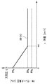
- FIG. 2 is a graph in which the horizontal axis represents the vehicle speed v (km / h) and the vertical axis represents the brake negative pressure PB (kPa).
- the brake negative pressure PB is larger than the atmospheric pressure in the region where the vehicle speed v exceeds the predetermined medium speed vs.
- the brake negative pressure PBs set on the negative pressure side is set to the negative pressure side.
- the brake negative pressure PBc close to the atmospheric pressure is detected between the vehicle speed zero and the predetermined medium speed vs.
- the brake negative pressure PBs set largely on the negative pressure side is set so as to change linearly.
- the vacuum pump The brake negative pressure is generated by actuating.
- the operation of the vacuum pump is stopped when it reaches the lower limit value PBm of the brake negative pressure in FIG.
- the naturally aspirated internal combustion engine is different from the internal combustion engine with a supercharger shown in FIG. 1 in that it includes a turbocharger 50 and an intercooler that include an intake compressor 50C, an exhaust turbine 50T, and a wastegate valve. Since only the 50IC is removed and the other components are the same, the illustration will be made on the assumption that they are removed instead of being illustrated again.
- blowby gas in the crankcase 1D is returned to the intake passage S (surge tank 4) using a PCV device (first blowby gas passage 13 and PCV valve 14) in a predetermined operating region.
- a PCV device first blowby gas passage 13 and PCV valve 14
- the PCV valve 14 is opened and the blow-by gas can be recirculated.
- the intake pressure Pk refers to the pressure in the intake passage S on the downstream side of the throttle valve 9, and specifically the intake pressure Pk in the surge tank 4 detected by the intake pressure sensor 40.
- the pressure is displayed as a gauge pressure expressed with a difference from the atmospheric pressure.
- a considerable amount (size) by which the maximum flow rate Gbmax is obtained by the PCV device in the operating region where the pressure is between P0 and P1.
- the crankcase ventilation flow rate Gb is obtained.
- the intake pressure range in the operation region where the PCV ventilation flow rate is not sufficient in this naturally aspirated internal combustion engine is shown in FIG. 3 as the PCV ventilation flow shortage region R1.
- the intake pressure P1 at which the shortage of the ventilation flow starts is hereinafter referred to as a shortage start intake pressure P1.
- FIG. 4 shows an example of the control routine for the naturally aspirated internal combustion engine described above. Such a routine is repeatedly executed by the ECU 100 at every predetermined calculation cycle.
- step S401 it is determined whether or not the brake negative pressure PB of the brake booster 20 detected by the pressure sensor 44 has a predetermined value. That is, it is determined whether or not the brake negative pressure PB is consumed (decreased) beyond the set line PB (v) set corresponding to the vehicle speed (PB ⁇ PB (v)?). If it is ensured (Yes), the process proceeds to step S402, and whether or not it is in the operation region where the crankcase ventilation flow rate Gb by the above-mentioned PCV device is insufficient, the intake pressure Pk is equal to or higher than the insufficient start intake pressure P1. It is determined whether the pressure is equal to or lower than the atmospheric pressure (P1 ⁇ Pk ⁇ 0). That is, it is determined whether or not the intake pressure Pk is in the ventilation flow shortage region R1 by the PCV device. If the determination in step S402 is no (No), this routine ends.
- step S402 if yes, the process proceeds to step S403, where the control valve 30 of the second blow-by gas passage 28 is opened and the operation of the electric vacuum pump 24 is started.
- the control valve 30 of the second blow-by gas passage 28 is opened and the operation of the electric vacuum pump 24 is started.
- the air is returned to the intake passage S near the surge tank 4 or the branch pipe 3 through the first blow-by gas passage 13 and the PCV valve 14.
- the blow-by gas in the crankcase 1D is sucked into the electric vacuum pump 24 through the oil separator 12, the second blow-by gas passage 28 and the opened control valve 30, and discharged from the discharge port 24out. Then, the refrigerant is returned to the intake passage S near the surge tank 4 or the branch pipe 3 through the pipe passage 36 and the pipe passage 38 provided with the fourth check valve CV4. Therefore, even if it is the ventilation flow shortage area
- step S401 determines whether the brake negative pressure PB of the brake booster 20 detected by the pressure sensor 44 is not secured (No). If it is determined in step S401 that the brake negative pressure PB of the brake booster 20 detected by the pressure sensor 44 is not secured (No), the process proceeds to step S404, and generation of the brake negative pressure is started. That is, the electric vacuum pump 24 is operated, and the brake negative pressure generation operation is continued until the brake negative pressure PB in the brake booster 20 falls below the setting line PB (v) and reaches the negative pressure lower limit value PBm in FIG. .
- the internal combustion engine with a supercharger is shown in FIG. 1, and as described above, the internal combustion engine includes an intake system compressor 50C, an exhaust system turbine 50T, and a wastegate valve. A feeder 50 and an intercooler 50IC are added.
- crankcase ventilation flow rate Gb (L / min) and the intake pressure Pk (kPa) in the intake passage S is as shown in FIG.
- the maximum flow rate Gbmax is obtained in the operation region where the intake pressure Pk is between the pressure P0 and the pressure P1 lower than the pressure P1.
- the pressure in the intake passage S on the downstream side of the PCV valve 14 becomes higher than the pressure in the crankcase 1D on the upstream side, so the PCV valve 14 cannot be opened, There is no reflux by the PCV device. That is, as the intake pressure Pk exceeds the pressure P1 and approaches the atmospheric pressure, the crankcase ventilation flow rate Gb begins to decrease as in the case of the naturally-intake type internal combustion engine, and it becomes difficult to satisfactorily perform the blow-by gas recirculation. As the intake pressure Pk increases, the crankcase ventilation flow rate Gb by the PCV device gradually decreases from the maximum flow rate Gbmax and finally becomes zero near the atmospheric pressure.
- FIG. 5 shows an intake pressure range of P1 ⁇ Pk ⁇ P2 including an operation region where the crankcase ventilation flow rate Gb by the PCV device is not sufficient and an operation region of zero as the PCV ventilation flow shortage region R2.
- FIG. 6 shows an example of the control routine of the internal combustion engine with a supercharger described above. Such a routine is repeatedly executed by the ECU 100 at every predetermined calculation cycle.
- step S601 it is determined whether or not the brake negative pressure PB of the brake booster 20 detected by the pressure sensor 44 has a predetermined value. That is, it is determined whether or not the brake negative pressure PB is consumed (decreased) beyond the set line PB (v) set corresponding to the vehicle speed (PB ⁇ PB (v)?). If it is secured (Yes), the process proceeds to step S602, and whether the intake pressure Pk is greater than the intake pressure P1 at which the intake pressure Pk starts to be insufficient and whether or not it is in the operation region where the crankcase ventilation flow rate Gb by the PCV device is insufficient. It is determined whether the pressure is equal to or lower than the intake pressure P2 (P1 ⁇ Pk ⁇ P2?). That is, it is determined whether or not the intake pressure Pk is in the ventilation flow shortage region R2 by the PCV device. If the determination in step S602 is no, this routine is terminated.
- step S602 If it is determined YES in step S602, the process proceeds to step S603, the control valve 30 of the second blow-by gas passage 28 is opened, and the operation of the electric vacuum pump 24 is started. As a result, at least a part of the blow-by gas in the crankcase 1D is introduced into the crankcase 1D from the intake passage S upstream of the air flow meter 7 via the fresh air introduction passage 16, and the oil separator 12 Then, the air is returned to the intake passage S near the surge tank 4 or the branch pipe 3 through the first blow-by gas passage 13 and the PCV valve 14.
- the blow-by gas in the crankcase 1D is sucked into the electric vacuum pump 24 through the oil separator 12, the second blow-by gas passage 28 and its control valve 30, and discharged from the discharge port 24out.
- the intake pressure Pk is lower than the atmospheric pressure in the non-supercharging region
- the intake air in the vicinity of the surge tank 4 or the branch pipe 3 through the pipe passage 36 and the pipe passage 38 provided with the fourth check valve CV4. It returns to the passage S.
- the intake pressure Pk is higher than the atmospheric pressure in the supercharging region, the intake air downstream of the inlet of the fresh air introduction passage 16 is upstream of the compressor 50C through the piping passage 32 provided with the second check valve CV2. It returns to the passage S.
- step S601 if it is determined in step S601 that the brake negative pressure PB of the brake booster 20 detected by the pressure sensor 44 is not secured (No), the process proceeds to step S604, and generation of the brake negative pressure is started. That is, the electric vacuum pump 24 is operated, and the brake negative pressure generation operation is continued until the brake negative pressure PB in the brake booster 20 falls below the setting line PB (v) and reaches the negative pressure lower limit value PBm in FIG. .
- the determination as to whether or not the operating state of these internal combustion engines is in the ventilation flow shortage region R1 and / or R2 by the PCV device This is performed based on the value of the intake pressure Pk.
- these determinations may be made based on the values of the parameters (for example, the rotational speed Ne and the load factor (the ratio of the load to the total load) Kl or the rotational speed and the intake air amount) representing the operating state of the internal combustion engine. .
- regions R1 ′ and / or R2 ′ corresponding to the above-described ventilation flow shortage regions R1 and / or R2 are determined in advance, and the actual rotational speed Ne and the load factor
- the electric vacuum pump 24 is turned on and the operation is started on the assumption that the operating state of the internal combustion engine is in the ventilation flow shortage region R1 and / or R2 by the PCV device. You may do it.
- the PCV device in both the naturally aspirated internal combustion engine and the internal combustion engine with a supercharger, the PCV device is sufficient in the low load operation region where the intake pressure Pk is lower than the intake pressure P1.
- a crankcase ventilation flow rate Gb (see thick solid line a) was obtained.
- the PCV ventilation flow shortage region R1 or R2 exists only in the operation region of the intake pressure Pk higher than the intake pressure P1.
- a sufficient crankcase ventilation flow rate Gb may not be obtained depending on the PCV device.
- ventilation in the crankcase is performed by the electric vacuum pump 24 in all the PCV ventilation flow shortage regions.
- the electric vacuum pump 24 is operated in this region.
- the operation is performed so that a constant flow rate is obtained when the intake pressure Pk is between the intake pressure P0 and the intake pressure P1 (see the broken line f), and when the intake pressure P1 exceeds the intake pressure P1, the flow rate increases at a predetermined rate (the broken line g). (See).
- an operation region range where the intake pressure Pk is from the intake pressure P0 to the intake pressure P2 is defined as a PCV ventilation flow shortage region R4.
- the pump 24 is activated. At this time, a constant flow rate is obtained when the intake pressure Pk is between the intake pressure P0 and the intake pressure P1 (see the broken line f), and at a predetermined rate until the intake pressure Pk exceeds the intake pressure P1 and reaches the atmospheric pressure. Is increased (see the broken line g), and the electric vacuum pump 24 is operated so that a constant flow rate is obtained (see the solid line j) during the supercharging pressure P2 exceeding the atmospheric pressure (see the solid line j).
- the electric vacuum pump is used as the vacuum pump.
- the vacuum pump is not limited to this, and a mechanical vacuum pump that is driven by the crankshaft of the internal combustion engine and controlled on and off by an electromagnetic clutch or the like is used. Needless to say.
Landscapes
- Engineering & Computer Science (AREA)
- Mechanical Engineering (AREA)
- General Engineering & Computer Science (AREA)
- Transportation (AREA)
- Lubrication Details And Ventilation Of Internal Combustion Engines (AREA)
- Valves And Accessory Devices For Braking Systems (AREA)
Abstract
ブレーキブースタの負圧源をなすと共に、ブローバイガスの吸気通路への還流にも利用可能なバキュームポンプを備える内燃機関のブローバイガス還流装置である。クランクケース内のブローバイガスを吸気通路に還流するためのPCV装置と、PCV装置によるクランクケース内のブローバイガスの換気流量が不足する運転領域か否かを判定する換気不足領域判定手段と、ブレーキブースタのブレーキ負圧が確保されているか否かを判定するブレーキ負圧判定手段と、を備える。そして、PCV装置によるクランクケース内のブローバイガスの換気流量が不足する運転領域と判定され、且つ、ブレーキ負圧が確保されていると判定されたときに限り、バキュームポンプによりクランクケース内のブローバイガスを換気するように構成されている。ブローバイガスとエンジンオイルとの接触機会を減らし、オイルの劣化を抑制する。
Description
本発明は、内燃機関のブローバイガス還流装置に関する。
一般に、内燃機関においては、その圧縮行程中にピストンとシリンダの隙間から未燃焼のガス(ブローバイガスと称される)が漏れ、このブローバイガス(特に、ガス中に含まれるNOx)はエンジンオイルに接触して酸化による劣化を助長することから、かかるエンジンオイルとの接触機会を減少すべくブローバイガスを機関の吸気系に還流して処理するブローバイガス還流装置が知られている。
例えば、特許文献1に記載のブローバイガス還流装置では、クランク室とシリンダヘッドカバー内部室とを連通する連通孔が設けられ、クランク室に溜まるブローバイガスがシリンダヘッドカバー内部室に誘導されて吸気通路に還流される。そして、ブレーキブースタに負圧を供給するバキュームポンプの吸込口と吐出口をそれぞれ上記のクランク室とシリンダヘッドカバー内部室とに導管を介して開口させると共に、当該クランク室に通じる導管に制御弁を配置し、クランク室とシリンダヘッドカバー内部室との圧力差が所定圧以上になった時に限り、当該制御弁を開くようにしている。これによって、当該制御弁が開かれたブローバイガス還流時に、バキュームポンプでクランク室内のブローバイガスを吸込みシリンダヘッドカバー内部室に送るようにしている。
しかしながら、特許文献1に記載されたブローバイガス還流装置においては、ブレーキブースタへ負圧を供給するバキュームポンプの吸込口と吐出口をそれぞれ上記のクランク室とシリンダヘッドカバー内部室とに導管を介して開口させると共に、当該クランク室に通じる導管に制御弁を配置し、クランク室とシリンダヘッドカバー内部室との圧力差が所定圧以上になった時に限り当該制御弁を開くようにしている。その結果、この圧力差が生じない限りクランク室内のブローバイガスは移動せず残存することになる。したがって、ブローバイガスとエンジンオイルとの接触機会が減少せず、オイルの劣化を十分に抑制できない。
また、クランク室内のブローバイガスはバキュームポンプに一旦吸込まれてシリンダヘッドカバー内部室に送られるが、このバキュームポンプによる吸込みに起因してクランク室内が負圧になるために、シリンダヘッドカバー内部室のブローバイガスがクランク室とシリンダヘッドカバー内部室とを連通する連通孔を介してクランク室に戻り、循環してしまう。この結果、クランク室内のブローバイガス濃度が薄くならず、オイル劣化抑制を十分に行うことができない。
さらに、ブレーキブースタに対してバキュームポンプから供給されるべき負圧が、ブローバイガスの還流のために費やされるのを抑えるために、バキュームポンプからクランク室への負圧の供給を、上述のように、クランク室とシリンダヘッドカバー内部室との圧力差が所定圧以上になった時に限っている。しかしながら、ブレーキブースタ内の負圧は、かかる圧力差とは無関係に、ブレーキペダルの操作回数などによっても変わるものであるから、ブレーキブースタ内の負圧が十分に確保されないことも起こり得る。
さらに、特許文献1に記載されたブローバイガス還流装置においては、機械式バキュームポンプが用いられている。これは、内燃機関により常時駆動されるため無駄仕事が多く燃費を悪化させる要因となっている。
そこで本発明は、上記事情に鑑みて創案され、その主たる目的は、バキュームポンプを利用する内燃機関のブローバイガス還流装置において、ブローバイガスとエンジンオイルとの接触機会を減らし、オイルの劣化を抑制することができる内燃機関のブローバイガス還流装置を提供することにある。
また、ブレーキブースタ内の負圧を常に十分に確保し、無駄仕事の少ない内燃機関のブローバイガス還流装置を提供することにある。
本発明の一の態様によれば、
ブレーキブースタの負圧源をなすと共に、ブローバイガスの吸気通路への還流にも利用可能なバキュームポンプを備える内燃機関のブローバイガス還流装置であって、
クランクケース内のブローバイガスを吸気通路に還流するためのPCV装置と、
当該PCV装置によるクランクケース内のブローバイガスの換気流量が不足する運転領域か否かを判定する換気不足領域判定手段と、
前記ブレーキブースタのブレーキ負圧が確保されているか否かを判定するブレーキ負圧判定手段と、を備え、
当該換気不足領域判定手段により前記PCV装置によるクランクケース内のブローバイガスの換気流量が不足する運転領域と判定され、且つ、当該ブレーキ負圧判定手段によりブレーキ負圧が確保されていると判定されたときに限り、前記バキュームポンプによりクランクケース内のブローバイガスを換気するように構成したことを特徴とする内燃機関のブローバイガス還流装置が提供される。
ブレーキブースタの負圧源をなすと共に、ブローバイガスの吸気通路への還流にも利用可能なバキュームポンプを備える内燃機関のブローバイガス還流装置であって、
クランクケース内のブローバイガスを吸気通路に還流するためのPCV装置と、
当該PCV装置によるクランクケース内のブローバイガスの換気流量が不足する運転領域か否かを判定する換気不足領域判定手段と、
前記ブレーキブースタのブレーキ負圧が確保されているか否かを判定するブレーキ負圧判定手段と、を備え、
当該換気不足領域判定手段により前記PCV装置によるクランクケース内のブローバイガスの換気流量が不足する運転領域と判定され、且つ、当該ブレーキ負圧判定手段によりブレーキ負圧が確保されていると判定されたときに限り、前記バキュームポンプによりクランクケース内のブローバイガスを換気するように構成したことを特徴とする内燃機関のブローバイガス還流装置が提供される。
このように構成された内燃機関のブローバイガス還流装置によれば、換気不足領域判定手段によりPCV装置によるクランクケース内のブローバイガスの換気流量が不足する運転領域と判定され、且つ、ブレーキ負圧判定手段によりブレーキ負圧が確保されていると判定されたときに限り、バキュームポンプによりクランクケース内のブローバイガスが換気される。したがって、ブレーキ負圧を確保しつつ、PCV装置により換気ができない分のブローバイガスをバキュームポンプによって確実に換気することができる。
ここで、前記バキュームポンプによりクランクケース内のブローバイガスを換気している間に、前記ブレーキ負圧判定手段によりブレーキ負圧が確保されていないと判定されたときは、前記バキュームポンプによるクランクケース内のブローバイガスの換気を中断し、前記バキュームポンプによりブレーキ負圧を生成するように構成することが好ましい。
この構成によると、バキュームポンプをクランクケース内のブローバイガス換気のために使用していても、ブレーキ負圧が必要量より不足すると、バキュームポンプによるクランクケース内のブローバイガスの換気が中断され、バキュームポンプによるブレーキ負圧の生成が優先して行われるので、ブレーキ負圧を必要量に満たすことができる。
ここで、前記内燃機関は自然吸気式の内燃機関であってもよい。この場合、前記PCV装置によるクランクケース内のブローバイガスの換気流量が不足する運転領域は、前記吸気通路の吸気圧が大気圧より低い負圧と大気圧との間の範囲にある領域であってもよい。
なお、前記内燃機関はコンプレッサを吸気通路に備える過給機付き内燃機関であってもよい。この場合、前記PCV装置によるクランクケース内のブローバイガスの換気流量が不足する運転領域は、前記吸気通路の吸気圧が大気圧より低い負圧と大気圧より高い正圧との間の範囲であってもよい。
さらに、ブローバイガスの前記吸気通路への還流にも利用可能なバキュームポンプは電動バキュームポンプであってもよい。この場合、前記クランクケース内と当該電動バキュームポンプの吸込口とを連通し、途中に開閉制御弁を有する配管通路と、当該電動バキュームポンプの吐出口とスロットルバルブの上流の吸気通路とを連通し、途中に逆止め弁を有する配管通路と、当該スロットルバルブより上流の吸気通路と前記クランクケース内とを連通する新気導入通路とを含んでもよい。
また、ブローバイガスの前記吸気通路への還流にも利用可能なバキュームポンプは電動バキュームポンプであり、前記クランクケース内と当該電動バキュームポンプの吸込口とを連通し、途中に開閉制御弁を有する配管通路と、当該電動バキュームポンプの吐出口と過給機のコンプレッサの上流の吸気通路とを連通し、途中に逆止め弁を有する配管通路と、当該過給機のコンプレッサのより上流の吸気通路と前記クランクケース内とを連通する新気導入通路とを含んでもよい。
かかる電動バキュームポンプを用いた構成によれば、無駄な仕事を減らすことができ燃費の向上ができる。
本発明によれば、ブローバイガスとエンジンオイルとの接触機会を大幅に減らすことができ、オイルの劣化を抑制することができるという、優れた効果が発揮される。
また、電動バキュームポンプを用いた構成によれば、無駄な仕事を減らすことができ燃費の向上を図ることができる。
さらに、新気導入通路を含んだ構成によれば、クランクケース内が常に新気により希釈されるので、ブローバイガス濃度を薄くすることができる。
以下、本発明の実施形態を添付図面に基づき説明する。なお本発明は以下の実施形態に限定されない。
図1は、本発明の一実施形態に係る過給機付き内燃機関のブローバイガス還流装置の構成を示す。本実施形態のブローバイガス還流装置は、ブレーキブースタを備えた車両に搭載された内燃機関(エンジン)Eに適用される。内燃機関Eはエンジン本体1を備え、エンジン本体1は周知のようにヘッドカバー1A、シリンダヘッド1B、シリンダブロック1C、クランクケース1Dおよびオイルパン1Eを含んで構成される。そしてエンジン本体1の内部にはピストン、コンロッドおよびクランクシャフト等が備えられ、同時に、シリンダヘッド1B及びシリンダブロック1Cには、これらを貫通する連通孔1Fが形成されている。この連通孔1Fによって、ヘッドカバー1A及びクランクケース1Dの内部が連通されている。図1に示す内燃機関Eは、過給機としてのターボチャージャ50を備えた多気筒ガソリンエンジンである。なお内燃機関Eの気筒数、シリンダ配置形式(直列、V型、水平対向等)等は特に限定されない。
各気筒の吸気ポートは気筒毎の枝管3を介して吸気集合室であるサージタンク4に接続されている。サージタンク4の上流側には吸気管5が接続されている。吸気管5には、上流側から順に、エアクリーナ6、吸入空気量を検出するためのエアフローメータ7、ターボチャージャ50のコンプレッサ50C、インタークーラ50IC、および電子制御式スロットルバルブ9が設けられている。吸気ポート、枝管3、サージタンク4及び吸気管5により吸気通路Sが形成される。なお図示はしないが、吸気ポート内には燃料を噴射するインジェクタ(燃料噴射弁)及び燃焼室には、点火プラグが気筒毎に設けられている。
一方、各気筒の排気ポートは不図示の排気マニフォールドを介して共通の排気管に接続される。これら排気ポート、排気マニフォールド及び排気管により排気通路が形成される。排気通路にはターボチャージャ50のタービン50Tが設置され、タービン50Tの下流側には三元触媒が設けられる。排気通路には、図示は省略するが、タービン50Tをバイパスするバイパス通路と、バイパス通路を開閉するための電子制御式ウェイストゲートバルブとが設けられる。ウェイストゲートバルブはスロットルバルブ9と同様のバタフライ弁とされ、その開度を無段階で変更可能である。
エンジン本体1のクランクケース1Dにはオイルセパレータ12が設けられている。オイルセパレータ12は、クランクケース1D内に連通されると共に、クランクケース1D内のブローバイガスを導入して、これに含まれるオイルを分離する。
オイルセパレータ12とサージタンク4又はその下流の枝管3とは第1ブローバイガス通路13により互いに連通され、第1ブローバイガス通路13にはPCV(Positive Crankcase Ventilation)バルブ14が設けられる。第1ブローバイガス通路13とPCVバルブ14はPCV装置を構成する。PCVバルブ14の開弁時、クランクケース1D内のブローバイガスはオイルセパレータ12、第1ブローバイガス通路13という経路を順に通じてサージタンク4に還流される。
また、ヘッドカバー1A内とエアフローメータ7の上流側の吸気通路Sとは新気導入通路16により互いに連通される。なお、オイルセパレータ12は第2ブローバイガス通路28を介して後述するブースタ通路26に連通されている。
他方、車両には、ドライバによるブレーキペダルの操作をアシストするためのブレーキブースタ20が設けられている。ブレーキブースタ20は、ブレーキ作動時、その負圧室に供給された負圧を利用してブレーキペダル操作力を倍力する。
ブレーキブースタ20の負圧室と電動バキュームポンプ24の吸込口24inとは、ブースタ通路26により互いに連通される。ブースタ通路26には、ブレーキブースタ20側から電動バキュームポンプ24側に向かう順流方向の空気の流れのみを許容し、逆流方向の空気の流れを禁止する第1逆止弁CV1が設けられている。第1逆止弁CV1により負圧室からの負圧抜けが防止される。また、オイルセパレータ12とブースタ通路26とは、第1逆止弁CV1と電動バキュームポンプ24の吸込口24inとの間の合流部X1で合流する第2ブローバイガス通路28により互いに連通されている。第2ブローバイガス通路28には、電磁開閉弁からなる制御弁30が設けられている。
制御弁30は、オイルセパレータ12から第2ブローバイガス通路28及びブースタ通路26を介して電動バキュームポンプ24に至るブローバイガスの流れを禁止する第1位置(閉位置)と、その流れを許容する第2位置(開位置)とを取り得る。
また、本実施の形態では、電動バキュームポンプ24の吐出口24outとターボチャージャ50のコンプレッサ50Cの上流の吸気通路Sとを連通する第3ブローバイガス通路32が設けられている。第3ブローバイガス通路32には、吸気通路Sから電動バキュームポンプ24側へのガスの流れを禁止する第2逆止弁CV2が設けられている。
さらに、ブレーキブースタ20と第1逆止弁CV1との間の合流部X2でブースタ通路26に合流する配管通路34、及び電動バキュームポンプ24の吐出口24outと第2逆止弁CV2との間の合流部X3で第3ブローバイガス通路32に合流する配管通路36とが合流部X4で合流され、配管通路38によってサージタンク4に連通されている。なお、配管通路34及び配管通路36には、それぞれ、サージタンク4からの逆流方向の空気の流れを禁止する第3逆止弁CV3及び第4逆止弁CV4が設けられている。
これらの配管通路34、36,38のうち、第3逆止弁CV3が設けられている配管通路34と配管通路38は、吸気圧がブレーキブースタ20のプレーキ負圧よりも低いときに、サージタンク4などからブレーキブースタ20の負圧室に負圧を供給するためのものである。吸気圧がプレーキ負圧よりも低いときは、第3の逆止め弁CV3を介してブレーキブースタ20の負圧室に負圧が供給される。そして、第4逆止弁CV4が設けられている配管通路36と配管通路38は、電動バキュームポンプ24の吐出口24outから吐出されるガスを負圧状態のサージタンク4に戻すためのものである。
さらに、本実施形態のブローバイガス還流装置には、制御部もしくは制御ユニットをなす電子制御ユニット(以下ECUという)100が備えられる。ECU100は、制御弁30および電動バキュームポンプ24に加え、前述のスロットルバルブ9、インジェクタ、点火プラグ、ウェイストゲートバルブをも制御するように構成されている。またECU100はこれらの他、内燃機関Eおよび車両の図示しない各種デバイスをも制御するように構成されている。
センサ類に関して、前述のエアフローメータ7に加え、特に、スロットルバルブ9より下流の吸気通路S内の圧力(吸気圧と称す)を検出するための吸気圧センサ40、内燃機関Eのクランク角を検出するためのクランク角センサ42、ブレーキブースタ20の負圧室の圧力を検出するための圧力センサ44及び車速センサ46がECU100に接続されている。
ECU100は、クランク角センサ42からのクランクパルス信号に基づき、クランク角自体を検出すると共にエンジンの回転数(rpm)を検出する。ここで「回転数」とは単位時間当たりの回転数のことをいい、回転速度と同義である。
ECU100は、エアフローメータ7からの信号に基づき、単位時間当たりの吸入空気の量である吸入空気量を検出する。そしてECU100は、検出した吸入空気量に基づきエンジン1の負荷を検出する。
また、本実施形態で用いられるブレーキブースタ20の負圧室に確保されるべきブレーキ負圧と車速との関係について図2を参照して説明する。図2は、横軸に車速v(km/h)、縦軸にブレーキ負圧PB(kPa)を取ったグラフである。一般に、車速vが高いほど制動時間が長くなり、あるいはより大きな制動力を要するので、ブレーキ負圧PBは車速vが所定の中速度vsより高速側に越える領域では、大気圧に対してより大きく負圧側に設定されたブレーキ負圧PBsとされている、一方、さほど大きな制動力を必要としないので、車速ゼロから当該所定の中速度vsまでの間では、大気圧に近いブレーキ負圧PBcから上述の大きく負圧側に設定されたブレーキ負圧PBsに直線的に変化するように設定されている。なお、このブレーキ負圧PBの設定線PB(v)を(図において上側に)越えて負圧が消費(減少)された場合、ブレーキ負圧PBの所定値が確保されていないとして、バキュームポンプが作動されることによりブレーキ負圧の生成が開始される。そして、ブレーキ負圧PBの生成の結果、これが図2のブレーキ負圧の下限値PBmに到達したときにバキュームポンプの作動は停止される。
ここで、本発明の第一の実施形態に係る自然吸気式内燃機関における本発明の作用を説明する。自然吸気式内燃機関は、図1に示した過給機付き内燃機関に対して、吸気系のコンプレッサ50Cと排気系のタービン50T及びウェイストゲートバルブを含んで構成される過給機50及びインタークーラ50ICを取除いて構成されるのみで、他の構成は同じであるので、改めて図示することは避け、それらが取除かれているとして説明する。
自然吸気式内燃機関では、所定の運転領域において、PCV装置(第1ブローバイガス通路13とPCVバルブ14)を用いてクランクケース1D内のブローバイガスを吸気通路S(サージタンク4)に還流することができる。すなわち、PCVバルブ14の下流(サージタンク4側)の圧力が上流側(クランクケース1D側)の圧力より低いので、PCVバルブ14が開き、ブローバイガスの還流を実行することができるのである。
すなわち、自然吸気式内燃機関では、吸気通路Sの吸気圧Pk(kPa)に対するクランクケース内換気流量Gb(L/min)の関係は図3に示すようになる。なお、吸気圧Pkとはスロットルバルブ9の下流側における吸気通路S内の圧力のことをいい、具体的には吸気圧センサ40により検出されるサージタンク4内の吸気圧Pkである。圧力は、大気圧を基準にしてその差をもって表すゲージ圧で表示される。この図3から明らかなように、吸気圧Pkが圧力P1より低い運転領域では、PCV装置によって圧力がP0とP1との間にある運転領域において最大流量Gbmaxが得られる相当な量(大きさ)のクランクケース内換気流量Gbが得られる。
しかし、吸気圧Pkが圧力P1と大気圧(吸気圧Pk=0)との間の運転領域範囲では、圧力P1を超えて大気圧に近づくにつれ、PCV装置によるブローバイガス還流量ないしはクランクケース内換気流量Gbが低下し始め、クランクケース内換気を満足に行うことが困難となる。すなわち、P1≦Pk≦0の吸気圧範囲では、吸気圧Pkが高まるにつれPCV装置によるクランクケース内換気流量Gbが太実線aで示す最大流量Gbmaxから徐々に低下し、最終的に0になる(細実線b参照)。この自然吸気式内燃機関におけるPCV換気流量が十分でない運転領域の吸気圧範囲は、PCV換気流量不足領域R1として図3に示されている。この換気流量の不足が始まる吸気圧P1を以下、不足開始吸気圧P1と称す。
そこで、本第一の実施形態の自然吸気式内燃機関では、吸気圧Pkが不足開始吸気圧P1になったとき、電動バキュームポンプ24を作動させると共に制御弁30を開き、電動バキュームポンプ24を利用してブローバイガスを還流する(図中破線c参照)。これにより、PCV装置によっては不足するクランクケース内換気流量Gbを補い、あるいは補完することができ(図中太実線d(=b+c)参照)、十分な量のクランクケース内換気流量Gbを得ることが可能となる。
図4に上述した自然吸気式内燃機関の制御ルーチンの一例を示す。かかるルーチンはECU100により所定の演算周期毎に繰り返し実行される。
ステップS401では、圧力センサ44により検出されたブレーキブースタ20のブレーキ負圧PBが所定値を確保しているか否かが判断される。すなわち、ブレーキ負圧PBが車速に対応して設定されている設定線PB(v)を越えて消費(減少)されているか否か(PB≦PB(v)?)が判断される。確保している(Yes)ときは、ステップS402に進み、上述のPCV装置によるクランクケース内換気流量Gbが不足する運転領域にあるか否か、吸気圧Pkが不足開始吸気圧P1以上であり大気圧以下か否か(P1≦Pk≦0)が判断される。すなわち吸気圧PkがPCV装置による換気流量不足領域R1に入っているか否かが判断される。ステップS402での判断がノー(No)の場合にはこのルーチンは終了される。
ステップS402において、イエス(Yes)の場合には、ステップS403に進み、第2ブローバイガス通路28の制御弁30が開かれると共に、電動バキュームポンプ24の作動が開始される。この結果、クランクケース1D内のブローバイガスは、当該クランクケース1Dに新気導入通路16を介してスロットルバルブ9より上流の吸気通路Sから導入される新気と共にその少なくとも一部が、オイルセパレータ12、第1ブローバイガス通路13とそのPCVバルブ14を介してサージタンク4又は枝管3付近の吸気通路Sに還流される。同時に、クランクケース1D内のブローバイガスは、オイルセパレータ12、第2ブローバイガス通路28とその開かれた制御弁30を介して電動バキュームポンプ24に吸引され、吐出口24outから吐出される。そして第4逆止弁CV4が設けられている配管通路36と配管通路38を通じてサージタンク4又は枝管3付近の吸気通路Sに還流される。したがって、PCV装置による換気流量不足領域R1であっても電動バキュームポンプ24によりブローバイガスの還流が行われ、ブローバイガスがクランクケース1D内に滞留するのが抑制される。
一方、ステップS401での判断において、圧力センサ44により検出されたブレーキブースタ20のブレーキ負圧PBが確保されていない(No)ときは、ステップS404に進み、ブレーキ負圧の生成が開始される。すなわち、電動バキュームポンプ24が作動され、ブレーキブースタ20内のブレーキ負圧PBが設定線PB(v)を下回り、図2の負圧下限値PBmに到達するまでブレーキ負圧生成作動が継続される。
次に、本発明の第二の実施形態に係る過給機付き内燃機関における本発明の作用を説明する。過給機付き内燃機関は図1に示され、また上述したように、自然吸気式内燃機関に対して、吸気系のコンプレッサ50Cと排気系のタービン50T及びウェイストゲートバルブを含んで構成される過給機50及びインタークーラ50ICが付加されて構成されている。
さて、本実施形態に係る過給機付き内燃機関において、過給が行われない非過給運転領域においては、上述の自然吸気式内燃機関と同様に作動する。そして、吸気通路Sの吸気圧Pk(kPa)に対するクランクケース内換気流量Gb(L/min)の関係は図5に示すようになる。この図5から明らかなように、吸気圧Pkが前述の不足開始吸気圧P1より低い運転領域では、吸気圧Pkが圧力P1より低い圧力P0と圧力P1との間にある運転領域で最大流量Gbmaxが得られる相当な大きさのクランクケース内換気流量Gbが、PCV装置により得られる。しかしながら、過給が行われる過給運転領域においては、PCVバルブ14の下流側の吸気通路Sの圧力が上流側のクランクケース1D内の圧力より高くなるので、PCVバルブ14が開弁できず、PCV装置による還流は行われない。すなわち、吸気圧Pkが圧力P1を超えて大気圧に近づくにつれ自然吸気式内燃機関と同様にクランクケース内換気流量Gbが低下し始めブローバイガス還流を満足に行うことが困難となる。そして、吸気圧Pkが高まるにつれPCV装置によるクランクケース内換気流量Gbは最大流量Gbmaxから徐々に低下し、大気圧付近で最終的にゼロになる。その後は、過給圧の上昇に伴い、このクランクケース内換気流量Gbがゼロのまま大気圧よりも高い正圧である過給圧P2まで維持される。図5には、このPCV装置によるクランクケース内換気流量Gbが十分でない運転領域とゼロの運転領域とを含むP1≦Pk≦P2の吸気圧範囲がPCV換気流量不足領域R2として示されている。
そこで、本実施形態の過給機付き内燃機関では、非過給運転領域において吸気圧Pkが圧力P1になったとき、電動バキュームポンプ24の作動を開始させると共に制御弁30を開き、電動バキュームポンプ24を利用してブローバイガスを還流する。これにより、PCV装置によっては不足するクランクケース内換気流量Gbを補い、あるいは補完する。さらに、過給運転領域においては、電動バキュームポンプ24のみにより、十分な量のクランクケース内換気流量Gbを得ることが可能となる。なお、図5において、a、b、c及びdは図3に示したものと同じであり、eは電動バキュームポンプ24のみによるクランクケース内換気流量Gbの最大値を示している。
図6に上述した過給機付き内燃機関の制御ルーチンの一例を示す。かかるルーチンはECU100により所定の演算周期毎に繰り返し実行される。
ステップS601では、圧力センサ44により検出されたブレーキブースタ20のブレーキ負圧PBが所定値を確保しているか否かが判断される。すなわち、ブレーキ負圧PBが車速に対応して設定されている設定線PB(v)を越えて消費(減少)されているか否か(PB≦PB(v)?)が判断される。確保している(Yes)ときは、ステップS602に進み、上述のPCV装置によるクランクケース内換気流量Gbが不足する運転領域にあるか否かを、吸気圧Pkが不足開始の吸気圧P1以上かつ吸気圧P2以下であるか否か(P1≦Pk≦P2?)が判断される。すなわち、吸気圧PkがPCV装置による換気流量不足領域R2に入っているか否かが判断される。ステップS602での判断がノー(No)の場合には、このルーチンは終了される。
ステップS602において、イエス(Yes)と判断された場合には、ステップS603に進み、第2ブローバイガス通路28の制御弁30が開かれると共に、電動バキュームポンプ24の作動が開始される。この結果、クランクケース1D内のブローバイガスは、当該クランクケース1Dに新気導入通路16を介してエアフローメータ7より上流の吸気通路Sから導入される新気と共にその少なくとも一部が、オイルセパレータ12、第1ブローバイガス通路13とそのPCVバルブ14を介してサージタンク4又は枝管3付近の吸気通路Sに還流される。同時に、クランクケース1D内のブローバイガスは、オイルセパレータ12、第2ブローバイガス通路28とその制御弁30を介して電動バキュームポンプ24に吸引され、吐出口24outから吐出される。このとき、非過給域で吸気圧Pkが大気圧よりも低い場合には、第4逆止弁CV4が設けられている配管通路36と配管通路38を通じてサージタンク4又は枝管3付近の吸気通路Sに還流される。一方、過給域で吸気圧Pkが大気圧よりも高い場合には、第2逆止弁CV2が設けられている配管通路32を通じてコンプレッサ50Cの上流で新気導入通路16の入口より下流の吸気通路Sに還流される。したがって、PCV装置による換気流量不足領域R2であっても電動バキュームポンプ24によりクランクケース内換気が行われ、ブローバイガスがクランクケース1D内に滞留するのが抑制される。なお、電動バキュームポンプ24からの吐出ガスをサージタンク4又は枝管3付近の吸気通路Sに還流させる形態は、電動バキュームポンプ24の駆動負荷を軽減することができる。
一方、ステップS601での判断において、圧力センサ44により検出されたブレーキブースタ20のブレーキ負圧PBが確保ていない(No)ときは、ステップS604に進み、ブレーキ負圧の生成が開始される。すなわち、電動バキュームポンプ24が作動され、ブレーキブースタ20内のブレーキ負圧PBが設定線PB(v)を下回り、図2の負圧下限値PBmに到達するまでブレーキ負圧生成作動が継続される。
なお、上述の自然吸気式内燃機関及び過給機付き内燃機関のいずれにおいても、これらの内燃機関の運転状態がPCV装置による換気流量不足領域R1及び/又はR2にあるか否かの判定を、吸気圧Pkの値に基づいて行なうようにした。しかしながら、これらの判定は、内燃機関の運転状態を表すパラメータ(例えば、回転数Neと負荷率(全負荷に対する負荷の割合)Kl又は回転数と吸入空気量)の値に基づいて行なってもよい。例えば、回転数Neと負荷率Klで規定されるマップにおいて、上述の換気流量不足領域R1及び/又はR2に対応する領域R1’及び/又はR2’を予め定め、実際の回転数Neと負荷率Klがこれらの領域R1’及び/又はR2’に入ったとき、内燃機関の運転状態がPCV装置による換気流量不足領域R1及び/又はR2にあるとして、電動バキュームポンプ24をオンにし作動を開始するようにしてもよい。
以上、本発明の好適な第一及び第二の実施形態を説明したが、本発明はさらに他の実施形態も可能である。例えば、図3及び図5に示したように、自然吸気式内燃機関及び過給機付き内燃機関のいずれにおいても、吸気圧Pkが吸気圧P1より低い低負荷運転領域においては、PCV装置により十分なクランクケース内換気流量Gb(太実線a参照)が得られるものとした。換言すると、この吸気圧P1より高い吸気圧Pkの運転領域にのみ、PCV換気流量不足領域R1、又はR2が存するものとした。しかしながら、内燃機関によっては、喩え吸気圧Pkが吸気圧P1より低い低負荷運転領域であっても、PCV装置によっては十分なクランクケース内換気流量Gbが得られない場合がある。
そこで、本発明の第三及び第四の実施形態では、全てのPCV換気流量不足領域において、電動バキュームポンプ24によりクランクケース内換気を行うようにしている。
具体的には、自然吸気式内燃機関の場合には、図7に示すように、例えば、吸気圧Pkが吸気圧P0から大気圧(Pk=0)までの運転領域範囲をPCV換気流量不足領域R3として、この領域で電動バキュームポンプ24を作動させている。このとき、吸気圧Pkが吸気圧P0から吸気圧P1の間では一定の流量が得られる(破線f参照)ように作動させ、吸気圧P1を超えると所定の割合で流量が増大する(破線g参照)ように作動させる。
過給機付き内燃機関の場合には、図8に示すように、例えば、吸気圧Pkが吸気圧P0から吸気圧P2までの運転領域範囲をPCV換気流量不足領域R4として、この領域で電動バキュームポンプ24を作動させている。このとき、吸気圧Pkが吸気圧P0から吸気圧P1の間では一定の流量が得られる(破線f参照)ように、また、吸気圧P1を超えて大気圧に至るまでは所定の割合で流量が増大する(破線g参照)ように、そして大気圧を超える過給圧P2の間では一定の流量が得られる(実線j参照)ように電動バキュームポンプ24を作動させる。
また、上述の実施形態では、バキュームポンプとして電動バキュームポンプを用いたが、これに限られずに、内燃機関のクランクシャフトで駆動され、電磁クラッチなどでオンオフ制御される機械式のバキュームポンプを用いてもよいことは言うまでもない。
本発明の実施形態には、特許請求の範囲によって規定される本発明の思想に包含されるあらゆる変形例や応用例、均等物が含まれる。従って本発明は、限定的に解釈されるべきではなく、本発明の思想の範囲内に帰属する他の任意の技術にも適用することが可能である。
Claims (6)
- ブレーキブースタの負圧源をなすと共に、ブローバイガスの吸気通路への還流にも利用可能なバキュームポンプを備える内燃機関のブローバイガス還流装置であって、
クランクケース内のブローバイガスを吸気通路に還流するためのPCV装置と、
前記PCV装置によるクランクケース内のブローバイガスの換気流量が不足する運転領域か否かを判定する換気不足領域判定手段と、
前記ブレーキブースタのブレーキ負圧が確保されているか否かを判定するブレーキ負圧判定手段と、を備え、
前記換気不足領域判定手段により前記PCV装置によるクランクケース内のブローバイガスの換気流量が不足する運転領域と判定され、且つ、前記ブレーキ負圧判定手段によりブレーキ負圧が確保されていると判定されたときに限り、前記バキュームポンプによりクランクケース内のブローバイガスを換気するように構成したことを特徴とする内燃機関のブローバイガス還流装置。 - 前記バキュームポンプによりクランクケース内のブローバイガスを換気している間に、前記ブレーキ負圧判定手段によりブレーキ負圧が確保されていないと判定されたときは、前記バキュームポンプによるクランクケース内のブローバイガスの換気を中断し、前記バキュームポンプによりブレーキ負圧を生成するように構成したことを特徴とする請求項1に記載の内燃機関のブローバイガス還流装置。
- 前記内燃機関は自然吸気式の内燃機関であり、前記PCV装置によるクランクケース内のブローバイガスの換気流量が不足する運転領域は、前記吸気通路の吸気圧が大気圧より低い負圧と大気圧との間の範囲にある領域であることを特徴とする請求項2に記載の内燃機関のブローバイガス還流装置。
- 前記内燃機関はコンプレッサを吸気通路に備える過給機付き内燃機関であり、前記PCV装置によるクランクケース内のブローバイガスの換気流量が不足する運転領域は、前記吸気通路の吸気圧が大気圧より低い負圧と大気圧より高い正圧との間の範囲であることを特徴とする請求項2に記載の内燃機関のブローバイガス還流装置。
- ブローバイガスの前記吸気通路への還流にも利用可能なバキュームポンプは電動バキュームポンプであり、前記クランクケース内と前記電動バキュームポンプの吸込口とを連通し、途中に開閉制御弁を有する配管通路と、前記電動バキュームポンプの吐出口とスロットルバルブの上流の吸気通路とを連通し、途中に逆止め弁を有する配管通路と、
前記スロットルバルブより上流の吸気通路と前記クランクケース内とを連通する新気導入通路とを含むことを特徴とする請求項3に記載の内燃機関のブローバイガス還流装置。 - ブローバイガスの前記吸気通路への還流にも利用可能なバキュームポンプは電動バキュームポンプであり、前記クランクケース内と前記電動バキュームポンプの吸込口とを連通し、途中に開閉制御弁を有する配管通路と、前記電動バキュームポンプの吐出口と過給機のコンプレッサの上流の吸気通路とを連通し、途中に逆止め弁を有する配管通路と、前記過給機のコンプレッサより上流の吸気通路と前記クランクケース内とを連通する新気導入通路とを含むことを特徴とする請求項4に記載の内燃機関のブローバイガス還流装置。
Priority Applications (3)
| Application Number | Priority Date | Filing Date | Title |
|---|---|---|---|
| DE112016003183.1T DE112016003183T5 (de) | 2015-07-14 | 2016-06-30 | Blow-by-Gas-Rezirkulationsvorrichtung für einen Verbrennungsmotor |
| US15/738,436 US10655515B2 (en) | 2015-07-14 | 2016-06-30 | Blow-by gas recirculation device for internal combustion engine |
| CN201680040047.8A CN107735550B (zh) | 2015-07-14 | 2016-06-30 | 内燃机的窜气回流装置 |
Applications Claiming Priority (2)
| Application Number | Priority Date | Filing Date | Title |
|---|---|---|---|
| JP2015-140709 | 2015-07-14 | ||
| JP2015140709A JP6330744B2 (ja) | 2015-07-14 | 2015-07-14 | 内燃機関のブローバイガス還流装置 |
Publications (1)
| Publication Number | Publication Date |
|---|---|
| WO2017010054A1 true WO2017010054A1 (ja) | 2017-01-19 |
Family
ID=57757250
Family Applications (1)
| Application Number | Title | Priority Date | Filing Date |
|---|---|---|---|
| PCT/JP2016/003152 Ceased WO2017010054A1 (ja) | 2015-07-14 | 2016-06-30 | 内燃機関のブローバイガス還流装置 |
Country Status (5)
| Country | Link |
|---|---|
| US (1) | US10655515B2 (ja) |
| JP (1) | JP6330744B2 (ja) |
| CN (1) | CN107735550B (ja) |
| DE (1) | DE112016003183T5 (ja) |
| WO (1) | WO2017010054A1 (ja) |
Families Citing this family (6)
| Publication number | Priority date | Publication date | Assignee | Title |
|---|---|---|---|---|
| US11454147B2 (en) * | 2020-09-21 | 2022-09-27 | Caterpillar Inc. | Internal combustion engine with purge system |
| CN112901309A (zh) * | 2021-02-05 | 2021-06-04 | 北京盛瑞科智能科技合伙企业(有限合伙) | 一种主动式两冲程发动机曲轴箱通风系统 |
| KR102842811B1 (ko) * | 2021-05-31 | 2025-08-05 | 현대자동차 주식회사 | 브레이크 부압 형성 시스템 및 방법 |
| US20230119867A1 (en) * | 2021-10-19 | 2023-04-20 | Svmtech, Llc | Pollution control system for diesel engine |
| US11598295B1 (en) * | 2021-12-27 | 2023-03-07 | Ford Global Technologies, Llc | Pump driven crankcase ventilation system |
| CN119467051A (zh) * | 2024-11-14 | 2025-02-18 | 重庆小康动力有限公司 | 曲轴箱负压控制系统、曲轴箱负压控制方法以及汽车 |
Citations (2)
| Publication number | Priority date | Publication date | Assignee | Title |
|---|---|---|---|---|
| JPS62279220A (ja) * | 1986-05-27 | 1987-12-04 | Toyota Motor Corp | 内燃機関のブロ−バイガス還流装置 |
| JP2006132360A (ja) * | 2004-11-04 | 2006-05-25 | Nissan Motor Co Ltd | 内燃機関のブローバイガス処理装置 |
Family Cites Families (6)
| Publication number | Priority date | Publication date | Assignee | Title |
|---|---|---|---|---|
| JP5494206B2 (ja) | 2010-05-11 | 2014-05-14 | トヨタ自動車株式会社 | 内燃機関のブローバイガス処理装置 |
| US9103246B2 (en) * | 2010-11-02 | 2015-08-11 | Ford Global Technologies, Llc | System and method for reducing vacuum degradation in a vehicle |
| US9097149B2 (en) * | 2012-07-13 | 2015-08-04 | Ford Global Technologies, Llc | Aspirator for crankcase ventilation and vacuum generation |
| US8955500B2 (en) * | 2013-03-01 | 2015-02-17 | GM Global Technology Operations LLC | Positive crankcase ventilation system |
| US10024251B2 (en) * | 2015-06-18 | 2018-07-17 | Ford Global Technologies, Llc | Method for crankcase ventilation in a boosted engine |
| JP6332177B2 (ja) * | 2015-07-14 | 2018-05-30 | トヨタ自動車株式会社 | 内燃機関のブローバイガス還流装置 |
-
2015
- 2015-07-14 JP JP2015140709A patent/JP6330744B2/ja not_active Expired - Fee Related
-
2016
- 2016-06-30 WO PCT/JP2016/003152 patent/WO2017010054A1/ja not_active Ceased
- 2016-06-30 CN CN201680040047.8A patent/CN107735550B/zh not_active Expired - Fee Related
- 2016-06-30 DE DE112016003183.1T patent/DE112016003183T5/de not_active Withdrawn
- 2016-06-30 US US15/738,436 patent/US10655515B2/en not_active Expired - Fee Related
Patent Citations (2)
| Publication number | Priority date | Publication date | Assignee | Title |
|---|---|---|---|---|
| JPS62279220A (ja) * | 1986-05-27 | 1987-12-04 | Toyota Motor Corp | 内燃機関のブロ−バイガス還流装置 |
| JP2006132360A (ja) * | 2004-11-04 | 2006-05-25 | Nissan Motor Co Ltd | 内燃機関のブローバイガス処理装置 |
Also Published As
| Publication number | Publication date |
|---|---|
| CN107735550A (zh) | 2018-02-23 |
| CN107735550B (zh) | 2019-11-05 |
| US10655515B2 (en) | 2020-05-19 |
| JP2017020459A (ja) | 2017-01-26 |
| JP6330744B2 (ja) | 2018-05-30 |
| US20180187582A1 (en) | 2018-07-05 |
| DE112016003183T5 (de) | 2018-03-29 |
Similar Documents
| Publication | Publication Date | Title |
|---|---|---|
| JP6332177B2 (ja) | 内燃機関のブローバイガス還流装置 | |
| JP6330744B2 (ja) | 内燃機関のブローバイガス還流装置 | |
| CN103906901B (zh) | 内燃机的换气控制装置 | |
| CN103511357B (zh) | 经由机械增压器供应真空的方法 | |
| US7275527B2 (en) | Method and apparatus for venting a crankcase of an internal combustion engine | |
| JP5822445B2 (ja) | ブローバイガス還流装置 | |
| US9657659B2 (en) | Method for reducing air flow in an engine at idle | |
| JP2013096247A (ja) | 内燃機関の制御装置 | |
| US10174650B2 (en) | Vehicle with integrated turbocharger oil control restriction | |
| JP2013124544A (ja) | 内燃機関 | |
| JP2008075589A (ja) | 内燃機関のegrガス掃気装置 | |
| JP2017015055A (ja) | ブローバイガス還流制御装置 | |
| JP2010038146A (ja) | エンジンの潤滑装置 | |
| JP2025067346A (ja) | 車両の制御装置 | |
| JP2017031898A (ja) | 内燃機関のブローバイガス還流装置 | |
| JP2012237231A (ja) | ブローバイガス還流装置 | |
| JP6341152B2 (ja) | 内燃機関のブローバイガス処理制御装置 | |
| JP2016160854A (ja) | 内燃機関のブローバイガス還流装置 | |
| JP6750220B2 (ja) | エンジンの制御装置 | |
| JP2011202591A (ja) | ブローバイガス還流装置 | |
| CN112424462A (zh) | 发动机的蒸发燃料处理装置 | |
| JP2013189887A (ja) | 制御装置 | |
| JP2013050060A (ja) | ブローバイガス処理装置 | |
| JP2017115653A (ja) | 内燃機関のブローバイガス還流装置 | |
| JP2017020465A (ja) | ブローバイガス還流制御装置 |
Legal Events
| Date | Code | Title | Description |
|---|---|---|---|
| 121 | Ep: the epo has been informed by wipo that ep was designated in this application |
Ref document number: 16824040 Country of ref document: EP Kind code of ref document: A1 |
|
| WWE | Wipo information: entry into national phase |
Ref document number: 112016003183 Country of ref document: DE |
|
| 122 | Ep: pct application non-entry in european phase |
Ref document number: 16824040 Country of ref document: EP Kind code of ref document: A1 |