WO2017006713A1 - 蓄電デバイス - Google Patents
蓄電デバイス Download PDFInfo
- Publication number
- WO2017006713A1 WO2017006713A1 PCT/JP2016/067614 JP2016067614W WO2017006713A1 WO 2017006713 A1 WO2017006713 A1 WO 2017006713A1 JP 2016067614 W JP2016067614 W JP 2016067614W WO 2017006713 A1 WO2017006713 A1 WO 2017006713A1
- Authority
- WO
- WIPO (PCT)
- Prior art keywords
- negative electrode
- storage device
- electricity storage
- alkali metal
- positive electrode
- Prior art date
- Legal status (The legal status is an assumption and is not a legal conclusion. Google has not performed a legal analysis and makes no representation as to the accuracy of the status listed.)
- Ceased
Links
Images


Classifications
-
- H—ELECTRICITY
- H01—ELECTRIC ELEMENTS
- H01G—CAPACITORS; CAPACITORS, RECTIFIERS, DETECTORS, SWITCHING DEVICES, LIGHT-SENSITIVE OR TEMPERATURE-SENSITIVE DEVICES OF THE ELECTROLYTIC TYPE
- H01G11/00—Hybrid capacitors, i.e. capacitors having different positive and negative electrodes; Electric double-layer [EDL] capacitors; Processes for the manufacture thereof or of parts thereof
- H01G11/22—Electrodes
- H01G11/30—Electrodes characterised by their material
- H01G11/48—Conductive polymers
-
- H—ELECTRICITY
- H01—ELECTRIC ELEMENTS
- H01G—CAPACITORS; CAPACITORS, RECTIFIERS, DETECTORS, SWITCHING DEVICES, LIGHT-SENSITIVE OR TEMPERATURE-SENSITIVE DEVICES OF THE ELECTROLYTIC TYPE
- H01G11/00—Hybrid capacitors, i.e. capacitors having different positive and negative electrodes; Electric double-layer [EDL] capacitors; Processes for the manufacture thereof or of parts thereof
- H01G11/04—Hybrid capacitors
- H01G11/06—Hybrid capacitors with one of the electrodes allowing ions to be reversibly doped thereinto, e.g. lithium ion capacitors [LIC]
-
- H—ELECTRICITY
- H01—ELECTRIC ELEMENTS
- H01G—CAPACITORS; CAPACITORS, RECTIFIERS, DETECTORS, SWITCHING DEVICES, LIGHT-SENSITIVE OR TEMPERATURE-SENSITIVE DEVICES OF THE ELECTROLYTIC TYPE
- H01G11/00—Hybrid capacitors, i.e. capacitors having different positive and negative electrodes; Electric double-layer [EDL] capacitors; Processes for the manufacture thereof or of parts thereof
- H01G11/22—Electrodes
- H01G11/30—Electrodes characterised by their material
- H01G11/32—Carbon-based
-
- H—ELECTRICITY
- H01—ELECTRIC ELEMENTS
- H01G—CAPACITORS; CAPACITORS, RECTIFIERS, DETECTORS, SWITCHING DEVICES, LIGHT-SENSITIVE OR TEMPERATURE-SENSITIVE DEVICES OF THE ELECTROLYTIC TYPE
- H01G11/00—Hybrid capacitors, i.e. capacitors having different positive and negative electrodes; Electric double-layer [EDL] capacitors; Processes for the manufacture thereof or of parts thereof
- H01G11/22—Electrodes
- H01G11/30—Electrodes characterised by their material
- H01G11/32—Carbon-based
- H01G11/34—Carbon-based characterised by carbonisation or activation of carbon
-
- H—ELECTRICITY
- H01—ELECTRIC ELEMENTS
- H01G—CAPACITORS; CAPACITORS, RECTIFIERS, DETECTORS, SWITCHING DEVICES, LIGHT-SENSITIVE OR TEMPERATURE-SENSITIVE DEVICES OF THE ELECTROLYTIC TYPE
- H01G11/00—Hybrid capacitors, i.e. capacitors having different positive and negative electrodes; Electric double-layer [EDL] capacitors; Processes for the manufacture thereof or of parts thereof
- H01G11/22—Electrodes
- H01G11/30—Electrodes characterised by their material
- H01G11/50—Electrodes characterised by their material specially adapted for lithium-ion capacitors, e.g. for lithium-doping or for intercalation
-
- H—ELECTRICITY
- H01—ELECTRIC ELEMENTS
- H01G—CAPACITORS; CAPACITORS, RECTIFIERS, DETECTORS, SWITCHING DEVICES, LIGHT-SENSITIVE OR TEMPERATURE-SENSITIVE DEVICES OF THE ELECTROLYTIC TYPE
- H01G11/00—Hybrid capacitors, i.e. capacitors having different positive and negative electrodes; Electric double-layer [EDL] capacitors; Processes for the manufacture thereof or of parts thereof
- H01G11/54—Electrolytes
- H01G11/58—Liquid electrolytes
- H01G11/62—Liquid electrolytes characterised by the solute, e.g. salts, anions or cations therein
-
- H—ELECTRICITY
- H01—ELECTRIC ELEMENTS
- H01M—PROCESSES OR MEANS, e.g. BATTERIES, FOR THE DIRECT CONVERSION OF CHEMICAL ENERGY INTO ELECTRICAL ENERGY
- H01M10/00—Secondary cells; Manufacture thereof
- H01M10/05—Accumulators with non-aqueous electrolyte
- H01M10/052—Li-accumulators
- H01M10/0525—Rocking-chair batteries, i.e. batteries with lithium insertion or intercalation in both electrodes; Lithium-ion batteries
-
- H—ELECTRICITY
- H01—ELECTRIC ELEMENTS
- H01M—PROCESSES OR MEANS, e.g. BATTERIES, FOR THE DIRECT CONVERSION OF CHEMICAL ENERGY INTO ELECTRICAL ENERGY
- H01M10/00—Secondary cells; Manufacture thereof
- H01M10/05—Accumulators with non-aqueous electrolyte
- H01M10/056—Accumulators with non-aqueous electrolyte characterised by the materials used as electrolytes, e.g. mixed inorganic/organic electrolytes
- H01M10/0564—Accumulators with non-aqueous electrolyte characterised by the materials used as electrolytes, e.g. mixed inorganic/organic electrolytes the electrolyte being constituted of organic materials only
- H01M10/0566—Liquid materials
-
- H—ELECTRICITY
- H01—ELECTRIC ELEMENTS
- H01M—PROCESSES OR MEANS, e.g. BATTERIES, FOR THE DIRECT CONVERSION OF CHEMICAL ENERGY INTO ELECTRICAL ENERGY
- H01M4/00—Electrodes
- H01M4/02—Electrodes composed of, or comprising, active material
- H01M4/13—Electrodes for accumulators with non-aqueous electrolyte, e.g. for lithium-accumulators; Processes of manufacture thereof
- H01M4/137—Electrodes based on electro-active polymers
-
- H—ELECTRICITY
- H01—ELECTRIC ELEMENTS
- H01M—PROCESSES OR MEANS, e.g. BATTERIES, FOR THE DIRECT CONVERSION OF CHEMICAL ENERGY INTO ELECTRICAL ENERGY
- H01M4/00—Electrodes
- H01M4/02—Electrodes composed of, or comprising, active material
- H01M4/36—Selection of substances as active materials, active masses, active liquids
- H01M4/362—Composites
- H01M4/366—Composites as layered products
-
- H—ELECTRICITY
- H01—ELECTRIC ELEMENTS
- H01M—PROCESSES OR MEANS, e.g. BATTERIES, FOR THE DIRECT CONVERSION OF CHEMICAL ENERGY INTO ELECTRICAL ENERGY
- H01M4/00—Electrodes
- H01M4/02—Electrodes composed of, or comprising, active material
- H01M4/36—Selection of substances as active materials, active masses, active liquids
- H01M4/58—Selection of substances as active materials, active masses, active liquids of inorganic compounds other than oxides or hydroxides, e.g. sulfides, selenides, tellurides, halogenides or LiCoFy; of polyanionic structures, e.g. phosphates, silicates or borates
- H01M4/583—Carbonaceous material, e.g. graphite-intercalation compounds or CFx
- H01M4/587—Carbonaceous material, e.g. graphite-intercalation compounds or CFx for inserting or intercalating light metals
-
- H—ELECTRICITY
- H01—ELECTRIC ELEMENTS
- H01M—PROCESSES OR MEANS, e.g. BATTERIES, FOR THE DIRECT CONVERSION OF CHEMICAL ENERGY INTO ELECTRICAL ENERGY
- H01M4/00—Electrodes
- H01M4/02—Electrodes composed of, or comprising, active material
- H01M4/36—Selection of substances as active materials, active masses, active liquids
- H01M4/60—Selection of substances as active materials, active masses, active liquids of organic compounds
-
- H—ELECTRICITY
- H01—ELECTRIC ELEMENTS
- H01M—PROCESSES OR MEANS, e.g. BATTERIES, FOR THE DIRECT CONVERSION OF CHEMICAL ENERGY INTO ELECTRICAL ENERGY
- H01M4/00—Electrodes
- H01M4/02—Electrodes composed of, or comprising, active material
- H01M4/36—Selection of substances as active materials, active masses, active liquids
- H01M4/60—Selection of substances as active materials, active masses, active liquids of organic compounds
- H01M4/602—Polymers
- H01M4/606—Polymers containing aromatic main chain polymers
-
- H—ELECTRICITY
- H01—ELECTRIC ELEMENTS
- H01M—PROCESSES OR MEANS, e.g. BATTERIES, FOR THE DIRECT CONVERSION OF CHEMICAL ENERGY INTO ELECTRICAL ENERGY
- H01M4/00—Electrodes
- H01M4/02—Electrodes composed of, or comprising, active material
- H01M4/62—Selection of inactive substances as ingredients for active masses, e.g. binders, fillers
- H01M4/621—Binders
- H01M4/622—Binders being polymers
-
- H—ELECTRICITY
- H01—ELECTRIC ELEMENTS
- H01G—CAPACITORS; CAPACITORS, RECTIFIERS, DETECTORS, SWITCHING DEVICES, LIGHT-SENSITIVE OR TEMPERATURE-SENSITIVE DEVICES OF THE ELECTROLYTIC TYPE
- H01G11/00—Hybrid capacitors, i.e. capacitors having different positive and negative electrodes; Electric double-layer [EDL] capacitors; Processes for the manufacture thereof or of parts thereof
- H01G11/84—Processes for the manufacture of hybrid or EDL capacitors, or components thereof
- H01G11/86—Processes for the manufacture of hybrid or EDL capacitors, or components thereof specially adapted for electrodes
-
- H—ELECTRICITY
- H01—ELECTRIC ELEMENTS
- H01M—PROCESSES OR MEANS, e.g. BATTERIES, FOR THE DIRECT CONVERSION OF CHEMICAL ENERGY INTO ELECTRICAL ENERGY
- H01M4/00—Electrodes
- H01M4/02—Electrodes composed of, or comprising, active material
- H01M2004/021—Physical characteristics, e.g. porosity, surface area
-
- H—ELECTRICITY
- H01—ELECTRIC ELEMENTS
- H01M—PROCESSES OR MEANS, e.g. BATTERIES, FOR THE DIRECT CONVERSION OF CHEMICAL ENERGY INTO ELECTRICAL ENERGY
- H01M4/00—Electrodes
- H01M4/02—Electrodes composed of, or comprising, active material
- H01M4/13—Electrodes for accumulators with non-aqueous electrolyte, e.g. for lithium-accumulators; Processes of manufacture thereof
- H01M4/133—Electrodes based on carbonaceous material, e.g. graphite-intercalation compounds or CFx
-
- Y—GENERAL TAGGING OF NEW TECHNOLOGICAL DEVELOPMENTS; GENERAL TAGGING OF CROSS-SECTIONAL TECHNOLOGIES SPANNING OVER SEVERAL SECTIONS OF THE IPC; TECHNICAL SUBJECTS COVERED BY FORMER USPC CROSS-REFERENCE ART COLLECTIONS [XRACs] AND DIGESTS
- Y02—TECHNOLOGIES OR APPLICATIONS FOR MITIGATION OR ADAPTATION AGAINST CLIMATE CHANGE
- Y02E—REDUCTION OF GREENHOUSE GAS [GHG] EMISSIONS, RELATED TO ENERGY GENERATION, TRANSMISSION OR DISTRIBUTION
- Y02E60/00—Enabling technologies; Technologies with a potential or indirect contribution to GHG emissions mitigation
- Y02E60/10—Energy storage using batteries
-
- Y—GENERAL TAGGING OF NEW TECHNOLOGICAL DEVELOPMENTS; GENERAL TAGGING OF CROSS-SECTIONAL TECHNOLOGIES SPANNING OVER SEVERAL SECTIONS OF THE IPC; TECHNICAL SUBJECTS COVERED BY FORMER USPC CROSS-REFERENCE ART COLLECTIONS [XRACs] AND DIGESTS
- Y02—TECHNOLOGIES OR APPLICATIONS FOR MITIGATION OR ADAPTATION AGAINST CLIMATE CHANGE
- Y02E—REDUCTION OF GREENHOUSE GAS [GHG] EMISSIONS, RELATED TO ENERGY GENERATION, TRANSMISSION OR DISTRIBUTION
- Y02E60/00—Enabling technologies; Technologies with a potential or indirect contribution to GHG emissions mitigation
- Y02E60/13—Energy storage using capacitors
Definitions
- the present invention relates to a power storage device.
- Non-Patent Document 1 a lithium ion capacitor using activated carbon as a positive electrode and graphite as a negative electrode is known (see Non-Patent Document 1).
- a lithium ion capacitor it is known that lithium pre-doping is performed for the purpose of increasing the cell voltage, that is, lithium ions are occluded or supported in advance on the negative electrode (Patent Documents 1 to 3). reference).
- the cell tends to be deteriorated by overdischarge. Therefore, the lower limit voltage of the cell is restricted to prevent it, but the cell is deteriorated by overdischarge. It has been desired to suppress the above more easily.
- the present invention has been made to solve such a problem, and a main object of the present invention is to provide an electricity storage device that can more easily suppress deterioration of a cell due to overdischarge.
- the electricity storage device of the present invention An organic skeleton layer containing an aromatic compound that is a dicarboxylic acid anion having an aromatic ring structure; and an alkali metal element layer in which an alkali metal element coordinates to oxygen contained in the carboxylic acid anion to form a skeleton.
- a negative electrode provided with a layered structure;
- a positive electrode that expresses electric double layer capacity;
- overdischarge means discharging at a voltage lower than the lower limit voltage of the cell.
- This lower limit voltage may be, for example, a general lower limit voltage of 1.5 V when a graphite negative electrode is used, or 1.0 V.
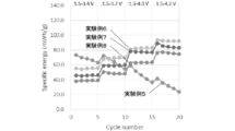
- FIG. 9 is a graph showing energy density under each charge / discharge condition in Experimental Examples 5 to 8.
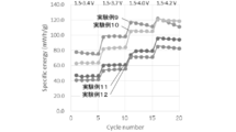
- 14 is a graph showing energy density under each charge / discharge condition of Experimental Examples 9 to 12.
- An electricity storage device of the present invention includes a negative electrode including the layered structure of the present invention, a positive electrode that expresses an electric double layer capacity, a non-aqueous electrolyte solution that is interposed between the negative electrode and the positive electrode and contains an alkali metal salt, It has.
- the layered structure of the present invention includes an organic skeleton layer containing an aromatic compound that is a dicarboxylic acid anion having an aromatic ring structure, and an alkali in which an alkali metal element coordinates to oxygen contained in the carboxylic acid anion to form a skeleton. And a metal element layer.
- the alkali metal contained in the alkali metal element layer can be any one or more of Li, Na, K, and the like, for example, but Li is preferable. Further, the alkali metal contained in the non-aqueous electrolyte solution and occluded / released in the layered structure by charging / discharging may be different from the alkali metal element contained in the alkali metal element layer, or the same. For example, any one or more of Li, Na, K, and the like can be used.
- a lithium ion capacitor in which Li is contained in the alkali metal element layer of the layered structure and an alkali metal that is occluded / released in the layered structure by charge / discharge is mainly described below.
- the negative electrode includes the above-described layered structure of the present invention as an active material.
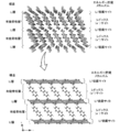
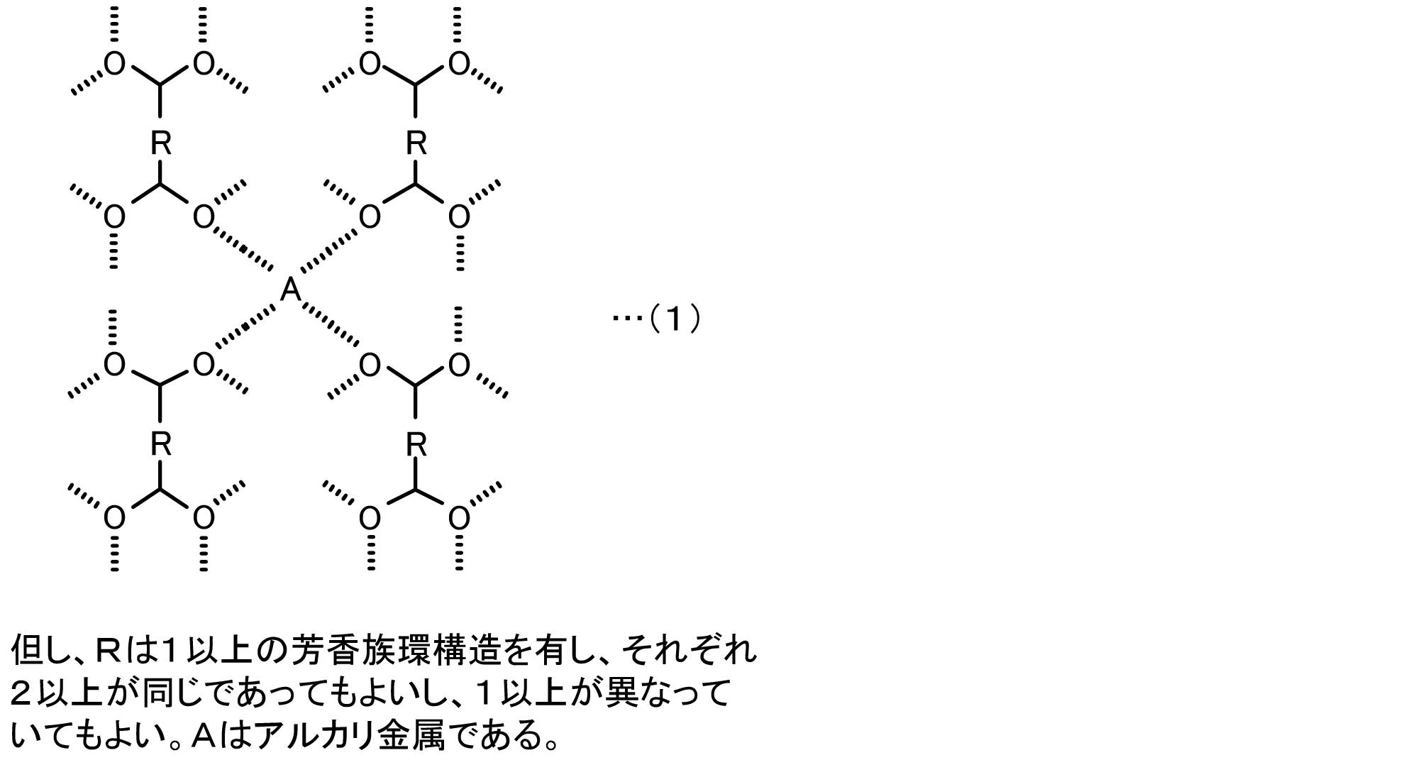
- FIG. 1 is an explanatory view showing an example of the structure of the layered structure of the present invention. It is structurally stable that this layered structure has a monoclinic crystal structure that is formed in layers by ⁇ -electron interaction of an aromatic compound and is assigned to the space group P2 1 / c. Yes, it is preferable. In addition, it is structurally preferable that the layered structure has a structure of the formula (1) in which four oxygen atoms of different dicarboxylic acid anions and an alkali metal element form a 4-coordination, which is preferable. .
- R has one or more aromatic ring structures, and two or more of a plurality of Rs may be the same or one or more may be different.
- A is an alkali metal element.
- the organic skeleton layer contains an aromatic compound that is a dicarboxylic acid anion having one or more aromatic ring structures.
- the aromatic compound may have one aromatic ring structure, but preferably has two or more aromatic ring structures. That is, R in the formula (1) preferably has two or more aromatic ring structures. This is because a layered structure is easily formed when the aromatic ring structure is 2 or more.
- the two or more aromatic ring structures may be, for example, an aromatic polycyclic compound in which two or more aromatic rings such as biphenyl are bonded, or a condensed polycycle in which two or more aromatic rings such as naphthalene, anthracene, and pyrene are condensed. It may be a compound.
- the aromatic compound preferably has an aromatic ring structure of 5 or less. This is because if the aromatic ring structure is 5 or less, the energy density can be further increased.
- This aromatic ring may be a 5-membered ring, a 6-membered ring or an 8-membered ring, and a 6-membered ring is preferred.
- This organic skeleton layer preferably contains an aromatic compound in which one of the dicarboxylic acid anions and the other of the carboxylic acid anions are bonded to diagonal positions of the aromatic ring structure. By doing so, it is easy to form a layered structure of the organic skeleton layer and the alkali metal element layer.
- the diagonal position to which the carboxylic acid is bonded may be the farthest position from the bonding position of one carboxylic acid to the bonding position of the other carboxylic acid.
- the aromatic ring structure is benzene, 1, 4 The position (para position) can be mentioned, and naphthalene includes the 2nd and 6th positions, and pyrene includes the 2nd and 7th positions.
- This organic skeleton layer may be composed of an aromatic compound including a structure represented by the formula (2).
- R may be the above aromatic ring structure having one or more aromatic ring structures.
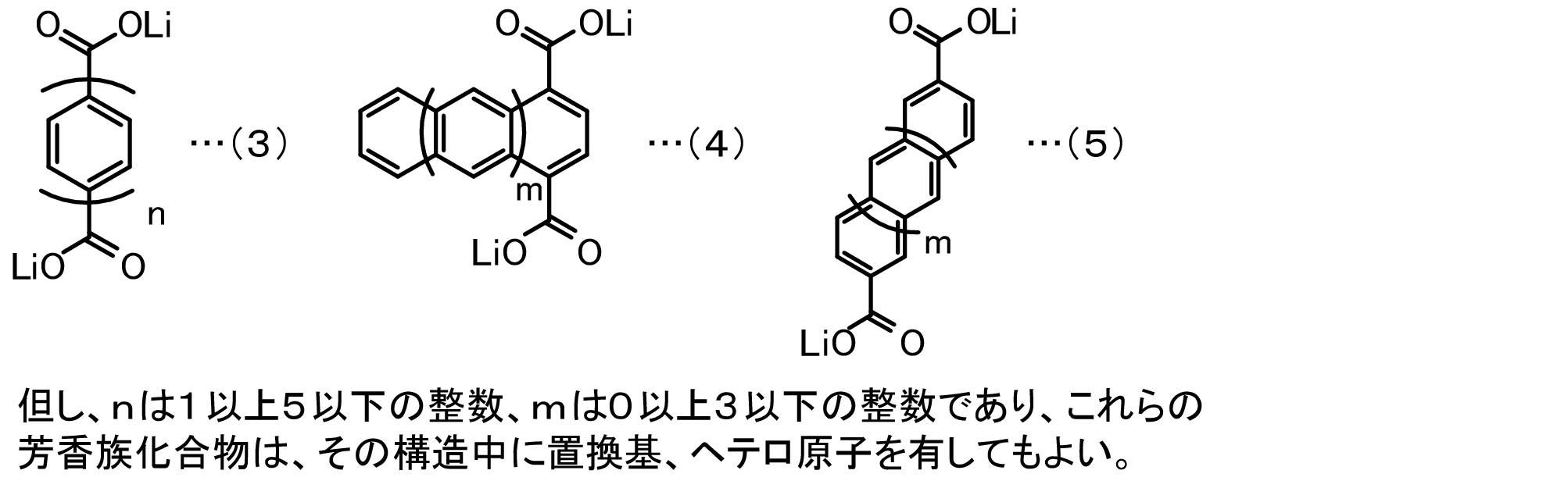
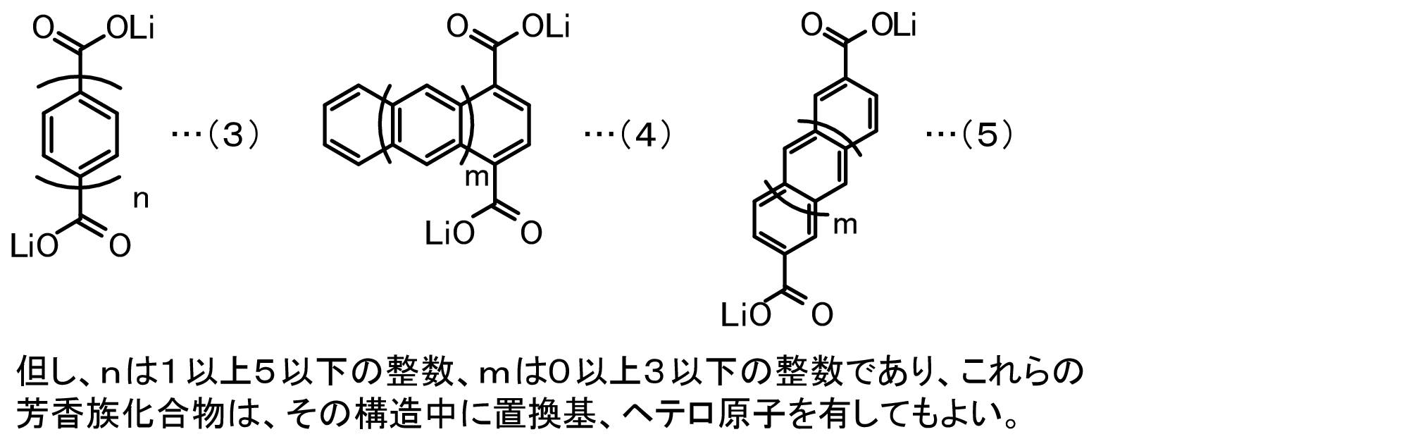
- the organic skeleton layer may include any one or more aromatic compounds of the following formulas (3) to (5).
- n is preferably an integer of 1 to 5
- m is preferably an integer of 0 to 3.
- n is 1 or more and 5 or less
- the size of the organic skeleton layer is suitable, and the charge / discharge capacity can be further increased.
- m is 0 or more and 3 or less
- the size of the organic skeleton layer is suitable, and the charge / discharge capacity can be further increased.
- these aromatic compounds may have a substituent or a hetero atom in the structure.
- Li represents Li constituting the alkali metal element layer.
- the alkali metal element layer has a skeleton formed by coordination of an alkali metal element with oxygen contained in a carboxylate anion.
- the alkali metal element may be any one or more of Li, Na, and K, and among these, Li is preferable. Since the alkali metal element contained in the alkali metal element layer forms the skeleton of the layered structure, it is presumed that the alkali metal element does not participate in ion migration accompanying charge / discharge, that is, is not occluded / released during charge / discharge.
- the layered structure thus configured is formed by an organic skeleton layer and a Li layer (alkali metal element layer) existing between the organic skeleton layers.
- the organic skeleton layer of the layered structure is considered to function as a redox (e ⁇ ) site, while the Li layer functions as a Li + storage site (alkali metal ion storage site). That is, this layered structure is considered to store and release energy as shown in the following formula (6). Furthermore, in this layered structure, a space where Li can enter may be formed in the organic skeleton layer, and Li can be occluded and released also in portions other than the alkali metal layer in Formula (6). It is assumed that the discharge capacity can be further increased.
- the negative electrode is prepared by mixing the above-described layered structure as an active material and other materials, adding a suitable solvent to form a paste-like negative electrode mixture, applying and drying on the surface of the current collector, You may compress and form so that an electrode density may be raised as needed.
- the negative electrode mixture preferably contains a water-soluble polymer.
- the water-soluble polymer may be at least one of carboxymethyl cellulose and polyvinyl alcohol. This water-soluble polymer may serve as a binder that binds the active material particles and the conductive material particles.
- Carboxymethyl cellulose may be, for example, an inorganic salt having a carboxymethyl group terminated with sodium or calcium, or an ammonium salt having a carboxymethyl group terminated with ammonium.
- the negative electrode mixture contains a water-soluble polymer
- the negative electrode mixture is preferably contained in a range of 2 mass% to 8 mass%. When the water-soluble polymer is contained in the range of 2% by mass or more, the capacity retention rate can be further increased.
- the adhesiveness of electrode materials or an electrode material and a collector is high.
- what contains a water-soluble polymer in 7 mass% or less is preferable, and what contains in 6 mass% or less is more preferable.
- the negative electrode mixture may contain a styrene butadiene copolymer in addition to the water-soluble polymer.
- the styrene-butadiene copolymer may serve as a binding material that binds the active material particles and the conductive material particles.
- a material containing a styrene-butadiene copolymer is preferable in that the active material particles can be bound more strongly.
- the negative electrode mixture includes a styrene butadiene copolymer
- the negative electrode mixture preferably includes the styrene butadiene copolymer in a range of 8% by mass or less. If the amount is 8% by mass or less, the amount of the active material, the conductive material, and the water-soluble polymer does not decrease too much, so that the functions of the active material, the conductive material, and the water-soluble polymer can be sufficiently exhibited.
- the negative electrode mixture preferably contains a conductive material.
- the conductive material is not particularly limited as long as it is an electron conductive material that does not adversely affect battery performance.
- graphite such as natural graphite (scale-like graphite, scale-like graphite) or artificial graphite, acetylene black, carbon black, ketjen
- a mixture of one or more of carbon materials such as black, carbon whisker, needle coke and carbon fiber, and metals (copper, nickel, aluminum, silver, gold, etc.) can be used.
- carbon black and acetylene black are preferable from the viewpoints of electron conductivity and coatability.
- the negative electrode mixture when the negative electrode mixture includes a conductive material, the negative electrode mixture preferably includes the conductive material in a range of 5% by mass to 15% by mass, and may be 7% by mass or more, or 9% by mass or more. If it is 5 mass% or more, sufficient electroconductivity can be given to an electrode and deterioration of a charge / discharge characteristic can be suppressed. Moreover, if it is 15 mass% or less, since an active material and a water-soluble polymer do not decrease too much, the function of an active material and a water-soluble polymer can fully be exhibited.
- the negative electrode mixture preferably contains the active material in the range of 70% by mass to 90% by mass, and may be in the range of 75% by mass to 85% by mass.
- the amount of the active material is less than 70% by mass. , which is preferable in that the active material can be increased to 70% by mass or more.
- the amount of the conductive material and the water-soluble polymer is not decreased too much, so that the functions of the conductive material and the water-soluble polymer can be sufficiently exhibited.
- the negative electrode mixture may include a binder instead of or in addition to the water-soluble polymer or styrene-butadiene copolymer described above.
- the binder serves to bind the active material particles and the conductive material particles.
- a binder for example, polytetrafluoroethylene (PTFE), polyvinylidene fluoride (PVdF), a fluorine-containing resin such as fluororubber, polypropylene,
- PTFE polytetrafluoroethylene
- PVdF polyvinylidene fluoride
- fluorine-containing resin such as fluororubber
- polypropylene polypropylene
- a thermoplastic resin such as polyethylene, ethylene-propylene-diene-monomer (EPDM) rubber, sulfonated EPDM rubber, natural butyl rubber (NBR), or the like may be used. These can be used alone or as a mixture of two or more.
- water As a solvent for dispersing the active material and other materials, water may be used.
- N-methylpyrrolidone, dimethylformamide, dimethylacetamide, methyl ethyl ketone, cyclohexanone, methyl acetate, methyl acrylate, diethylenetriamine, N, N -An organic solvent such as dimethylaminopropylamine, ethylene oxide, or tetrahydrofuran may be used.
- water is suitable when the water-soluble polymer or styrene butadiene copolymer described above is used as the binder.
- the application method include roller coating such as applicator roll, screen coating, doctor blade method, spin coating, bar coater, and the like, and any of these can be used to obtain an arbitrary thickness and shape.
- Current collectors include copper, nickel, stainless steel, titanium, aluminum, calcined carbon, conductive polymer, conductive glass, Al-Cd alloy, etc., for the purpose of improving adhesion, conductivity and reduction resistance.
- the surface of copper or the like treated with carbon, nickel, titanium, silver, or the like can also be used.
- the current collector of the negative electrode is more preferably aluminum metal. That is, the layered structure is preferably formed on an aluminum metal current collector. This is because aluminum is abundant and has excellent corrosion resistance. For these, the surface can be oxidized.
- Examples of the shape of the current collector include foil, film, sheet, net, punched or expanded, lath, porous, foam, and formed fiber group.
- the thickness of the current collector is, for example, 1 to 500 ⁇ m.
- the negative electrode is composed of an organic skeleton layer containing an aromatic compound that is a dicarboxylic acid anion having an aromatic ring structure (preferably a naphthalene skeleton or a benzene skeleton) and an alkali metal element coordinated to oxygen contained in the carboxylic acid anion.
- a negative electrode mixture containing a layered structure including an alkali metal element layer to be formed and a conductive material is formed on a current collector, and then in a temperature range of 250 ° C. to 450 ° C. in an inert atmosphere. It may be fired.
- the crystal structure can be made more suitable, the ⁇ -electron interaction of the aromatic compound can be increased, and the exchange of electrons can be facilitated, so that the charge / discharge characteristics can be further improved.
- the firing temperature is preferably 275 ° C. or higher, more preferably 350 ° C. or lower, and further preferably about 300 ° C.
- baking time is suitably selected according to baking temperature, the range of 2 hours or more and 24 hours or less is preferable, for example.
- the inert atmosphere may be, for example, a rare gas such as nitrogen gas, He, or Ar, and among these, Ar is preferable.
- the negative electrode may be pre-doped with alkali metal ions, that is, a metal ion previously occluded and / or supported. If it carries out like this, the cell voltage of an electrical storage device can be raised and charging / discharging capacity
- a cell having an alkali metal as a counter electrode may be separately assembled and a predetermined amount of alkali metal may be doped.
- an alkali metal may be disposed in the electricity storage device and doped with the alkali metal by electrochemical contact with the negative electrode.
- the positive electrode is not particularly limited as long as it exhibits electric double layer capacity, and a known positive electrode used for a capacitor, a lithium ion capacitor, or the like may be used.
- the positive electrode may include, for example, a carbon material.
- the carbon material is not particularly limited.
- activated carbons, cokes, glassy carbons, graphites, non-graphitizable carbons, pyrolytic carbons, carbon fibers, carbon nanotubes, Examples include polyacenes. Of these, activated carbons exhibiting a high specific surface area are preferred.
- Activated carbon as the carbon material preferably has a specific surface area of 1000 m 2 / g or more, and more preferably 1500 m 2 / g or more.
- the specific surface area of the activated carbon is preferably 3000 m 2 / g or less, and more preferably 2000 m 2 / g or less, from the viewpoint of ease of production.
- the positive electrode it is considered that at least one of an anion and a cation contained in the non-aqueous electrolyte is adsorbed / desorbed to store electricity. It is good also as what is desorbed and stored.
- the positive electrode for example, the above-mentioned carbon material, conductive material and binder are mixed, and an appropriate solvent is added to form a paste-like positive electrode mixture, which is applied to the surface of the current collector and dried.
- the electrode may be compressed to increase the electrode density.
- the conductive material, binder, solvent, and the like used for the positive electrode those exemplified for the negative electrode can be used.
- the positive electrode current collector includes aluminum and titanium for the purpose of improving adhesion, conductivity, and oxidation resistance. What processed the surface of copper etc. with carbon, nickel, titanium, silver, etc. can be used. For these, the surface can be oxidized.
- the shape of the current collector can be the same as that of the negative electrode.
- the positive electrode current collector may be the same as the negative electrode current collector.
- the positive electrode and the negative electrode have a capacity ratio B / A which is a ratio of the electric capacity B (mAh) of the negative electrode to the electric capacity A (mAh) of the positive electrode in the voltage range where charge and discharge are performed. Is preferably 6 or more, more preferably 7 or more. In this way, a high energy density can be stably obtained.
- the value of the capacity ratio B / A may be 20 or less, for example, or 15 or less. Within such a range, the amount of the negative electrode active material is not too much, and the negative electrode active material can be used more effectively.
- an organic solvent containing a supporting salt (supporting electrolyte)
- a supporting salt such as an alkali metal salt
- the alkali metal salt include lithium salts such as LiPF 6 , LiClO 4 , LiAsF 6 , LiBF 4 , Li (CF 3 SO 2 ) 2 N, LiN (C 2 F 5 SO 2 ) 2, and the like. Examples thereof include sodium salt and potassium salt.
- the concentration of the supporting salt is preferably 0.1 to 2.0M, and more preferably 0.8 to 1.2M.
- an aprotic organic solvent can be used as the organic solvent.
- examples of such an organic solvent include cyclic carbonates, chain carbonates, cyclic esters, cyclic ethers, chain ethers, and the like.
- Examples of the cyclic carbonate include ethylene carbonate, propylene carbonate, butylene carbonate, and vinylene carbonate.
- Examples of the chain carbonate include dimethyl carbonate, diethyl carbonate, and methyl ethyl carbonate.
- Examples of the cyclic ester carbonate include gamma butyrolactone and gamma valerolactone.
- Examples of the cyclic ether include tetrahydrofuran and 2-methyltetrahydrofuran.
- chain ether examples include dimethoxyethane and ethylene glycol dimethyl ether. These may be used alone or in combination.
- non-aqueous electrolyte nitrile solvents such as acetonitrile and propyl nitrile, ionic liquids, gel electrolytes, and the like may be used.
- the electricity storage device of the present invention may include a separator between the positive electrode and the negative electrode.
- the separator is not particularly limited as long as it is a composition that can withstand the usage range of the electricity storage device.
- a polymer nonwoven fabric such as a polypropylene nonwoven fabric or a polyphenylene sulfide nonwoven fabric, or an olefin resin such as polyethylene or polypropylene is used.
- a microporous film is mentioned. These may be used alone or in combination.
- FIG. 2 is a schematic diagram illustrating an example of the electricity storage device 10 according to the above-described embodiment.
- This power storage device 10 includes a positive electrode sheet 13 in which a positive electrode mixture 12 is formed on a current collector 11, a negative electrode sheet 18 in which a negative electrode mixture 17 is formed on the surface of a current collector 14, a positive electrode sheet 13, and a negative electrode sheet 18.
- the separator 19 is sandwiched between the positive electrode sheet 13 and the negative electrode sheet 18, wound and inserted into the cylindrical case 22, and connected to the positive electrode terminal 24 connected to the positive electrode sheet 13 and the negative electrode sheet.
- the negative electrode terminal 26 is disposed.
- the positive electrode mixture is provided with a material that exhibits electric double layer capacity.
- the negative electrode mixture includes an organic skeleton layer containing an aromatic compound that is a dicarboxylic acid anion having an aromatic ring structure, and an alkali metal element layer in which an alkali metal element is coordinated to oxygen contained in the carboxylic acid anion to form a skeleton. And a layered structure.
- cell deterioration due to overdischarge for example, cell deterioration due to generation of gas such as hydrogen gas or reaction of generated gas can be more easily suppressed.
- gas such as hydrogen gas or reaction of generated gas
- the reason why such an effect can be obtained is assumed as follows.
- the resistance rapidly increases and exhibits a shutdown function. For this reason, overdischarge hardly progresses, and as a result, deterioration of the cell due to overdischarge can be more easily suppressed.
- overdischarge tends to proceed particularly in the graphite negative electrode, but in the negative electrode using the layered structure of the present invention, before or after the overdischarge state, regardless of the presence or absence of pre-doping or Since the resistance of the negative electrode is rapidly increased before the overdischarge progresses and the shutdown function is exhibited, the deterioration of the cell due to the overdischarge can be more easily suppressed. In addition, if it charges after shutdown, the resistance of a negative electrode will fall as it is because a negative electrode occludes lithium ion, and it can charge / discharge again.
- Experimental examples 1, 3, 5 to 12 correspond to examples of the present invention
- experimental examples 2 and 4 correspond to comparative examples.
- the present invention is not limited to the following examples, and it goes without saying that the present invention can be carried out in various modes as long as they belong to the technical scope of the present invention.
- a non-aqueous electrolyte was prepared by adding lithium hexafluorophosphate to a solvent in which ethylene carbonate, dimethyl carbonate, and ethyl methyl carbonate were mixed at a volume ratio of 30:40:30 so as to be 1 mol / L.
- Two separators made by Toray Tonen impregnated with the above-mentioned non-aqueous electrolyte between the two electrodes, with the negative electrode of 2,6-naphthalenedicarboxylate negative electrode as the working electrode, lithium metal foil (thickness 300 ⁇ m) as the counter electrode, and two electrodes
- a polar evaluation cell was prepared.
- each energization condition in the intermittent charge / discharge test was set to 37 mAh / g discharge (or charge) at a current value of 0.15 mA, and the internal resistance R was set to about 140 ⁇ as the number of repetitions of the intermittent charge test It was the same as that of Experimental Example 1 except that it was reached.
- FIG. 3 and 4 show changes in internal resistance in Experimental Examples 1 and 2.
- FIG. The standardized capacity is the remaining capacity when the capacity reference 215 mAh / g is standardized as 1 in Experimental Example 1, and the remaining capacity when the capacity standard 360 mAh / g is standardized as 1 in Experimental Example 2 It is.
- the internal resistance change shown in FIGS. 3 and 4 is the cell discharge direction (from the layered structure) in the lithium ion capacitor using the 2,6-naphthalenedicarboxylate negative electrode or the graphite negative electrode as the negative electrode and the activated carbon electrode as the positive electrode. This corresponds to a change in internal resistance of the negative electrode in the direction in which lithium desorption proceeds).
- slurry-like composite material 0.0% by mass was mixed, and an appropriate amount of N-methyl-2-pyrrolidone was added and dispersed as a dispersion material to obtain a slurry-like composite material.
- This slurry-like mixture was uniformly applied to a 10 ⁇ m thick copper foil current collector and dried by heating to prepare a coated sheet. Thereafter, the coated sheet was pressure-pressed and punched out to an area of 2.05 cm 2 to prepare a disc-shaped negative electrode.
- Lithium hexafluorophosphate is added to a non-aqueous solvent in which ethylene carbonate, dimethyl carbonate, and ethyl methyl carbonate are mixed at a volume ratio of 30:40:30 so as to be 1 mol / L, thereby producing a non-aqueous electrolyte.
- a separator Teonen Tapyrus impregnated with the non-aqueous electrolyte was sandwiched between both electrodes to prepare a bipolar evaluation cell.
- Example 4 Li-occlusion state negative electrode as in Experimental Example 3, except that the graphite negative electrode of Experimental Example 2 was used as the negative electrode of the bipolar evaluation cell and was reduced (charged) to 0.05 V at 0.02 mA in a temperature environment of 20 ° C. The exotherm was measured.
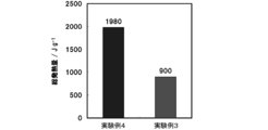
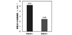
- FIG. 5 shows the results of differential scanning calorimetry in Experimental Examples 3 and 4. 6 shows the total heat generation amount of Experimental Examples 3 and 4, and FIG. 7 shows the total heat generation amount per capacity of Experimental Examples 3 and 4. 5 to 7, it was found that the calorific value of the lithium 2,6-naphthalenedicarboxylate negative electrode was smaller than that of the graphite negative electrode. Therefore, it was found that the use of a 2,6-naphthalenedicarboxylate negative electrode can be expected to reduce the calorific value as compared with a lithium ion capacitor using a graphite negative electrode.
- This slurry composite was uniformly applied to a 15 ⁇ m-thick aluminum foil current collector so that the activated carbon was 3 mg / cm 2 per unit area, and dried by heating to prepare a coated sheet. Thereafter, the coated sheet was pressure-pressed and punched out to an area of 2.05 cm 2 to prepare a disk-shaped electrode. Thereafter, baking was performed at 300 ° C. for 12 hours in an argon inert atmosphere.
- Lithium hexafluorophosphate is added to a non-aqueous solvent in which ethylene carbonate, dimethyl carbonate, and ethyl methyl carbonate are mixed at a volume ratio of 30:40:30 so as to be 1 mol / L, thereby producing a non-aqueous electrolyte.
- a bipolar evaluation cell was produced by sandwiching a separator (manufactured by Toray Tonen) impregnated with the above non-aqueous electrolyte between the above-described lithium 2,6-naphthalenedicarboxylate negative electrode and an activated carbon positive electrode.
- This lithium 2,6-naphthalenedicarboxylate negative electrode was previously prepared by using a 2,6-naphthalenedicarboxylic acid lithium electrode as a working electrode and a lithium metal foil (thickness 300 ⁇ m) as a counter electrode, and the non-aqueous electrolyte between the electrodes.
- a bipolar evaluation cell is made with a separator impregnated with Toray Tonen, reduced to 0.5 V at 0.075 mA in a temperature environment of 20 ° C., and then oxidized to 1.5 V at 0.075 mA. Then, the capacity density of the electrode was calculated, and an electrode reduced to half the capacity density was used.
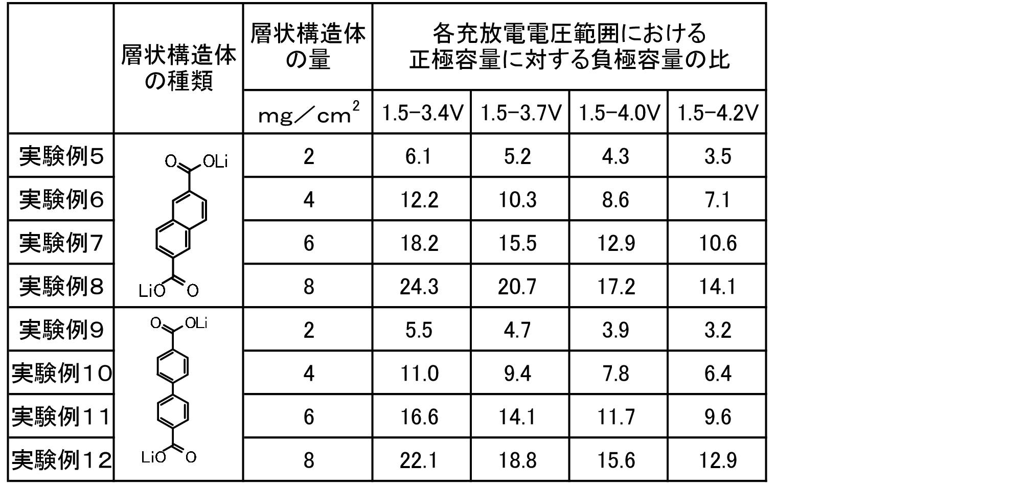
- Table 1 shows the capacity ratio B / A of the electric capacity B (mAh) of the negative electrode to the electric capacity A (mAh) of the positive electrode in each charge / discharge voltage range.
- 8 and 9 show the energy density under each charge / discharge condition of Experimental Examples 5 to 8 and Experimental Examples 9 to 12. It has been found that when the capacity ratio B / A is 6 or more, more stable cycle characteristics are obtained, and when the capacity ratio B / A is 7 or more, more stable cycle characteristics are obtained. Further, in the negative electrode using lithium 2,6-naphthalenedicarboxylate, when lithium 2,6-naphthalenedicarboxylate is used in an amount of 4 mg / cm 2 or more, the energy density per total weight of the positive and negative electrode active materials is 40 to 90 Wh.
- the negative electrode including the layered structure of the present invention can use a larger capacity than the capacity (about 70 mAh / g) that can actually be used in a graphite negative electrode used for a general lithium ion capacitor. I understood.
- the energy density can be further increased because charging and discharging can be performed at the same voltage as when a graphite negative electrode is used.
- Lithium hexafluorophosphate is added to a non-aqueous solvent in which ethylene carbonate, dimethyl carbonate, and ethyl methyl carbonate are mixed at a volume ratio of 30:40:30 so as to be 1 mol / L, thereby producing a non-aqueous electrolyte. did.
- the above-mentioned lithium 2,6-naphthalenedicarboxylate electrode is used as a working electrode
- a lithium metal foil (thickness 300 ⁇ m) is used as a counter electrode
- a separator made by Toray Tonen impregnated with the above non-aqueous electrolyte is sandwiched between both electrodes.
- a bipolar evaluation cell was prepared.
- a cell was prepared in the same manner as in Reference Example 1 except that the configuration of the negative electrode was changed to that shown in Table 2 in the preparation of the coated electrode, and a charge / discharge test was performed.
- fibrous carbon vapor-grown carbon fiber, manufactured by Showa Denko, VGCF (diameter: about 150 nm, length: about 10 to 20 ⁇ m)
- polyfluoride is used as the binder.
- Vinylidene was used and N-methyl-2-pyrrolidone was used as a dispersant.
- Table 2 shows the results of the maximum capacity, initial efficiency, and capacity retention rate of Reference Examples 1 to 12.
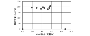
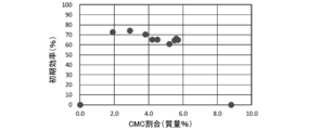
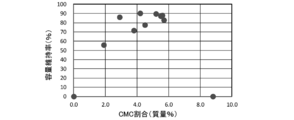
- 10 to 12 are graphs showing the relationship between the CMC ratio and the maximum capacity, initial efficiency, and capacity maintenance rate. From Table 2, the CMC-based binder was compared with Reference Example 10 in which the CMC-based binder was not used, Reference Example 11 in which the CMC-based binder was excessive, and Reference Example 12 in which the PVdF-based binder was used. It was found that Reference Examples 1 to 8 in which the dressing material was used at a ratio of 2% by mass or more and 8% by mass or less were excellent in all of the maximum capacity, initial efficiency, and capacity retention rate.
- the active material and the conductive material are more uniformly mixed and closely adhered to the current collector, so that the occurrence of a heterogeneous reaction in the electrode can be suppressed. It was inferred that the discharge characteristics could be further improved. 10 and 11, it was found that the maximum capacity and the initial efficiency can be further increased if the CMC in the electrode is 8.0% by mass or less. Further, FIG. 12 indicates that the capacity retention rate can be further increased when the CMC in the electrode is 2.0 mass% or more and 8.0 mass% or less. In Reference Example 9 where the CMC in the electrode is 1.9% by mass, the maximum capacity and initial efficiency are equivalent to those of Reference Examples 1 to 8, but the capacity retention rate is 10% or more than that of Reference Examples 1 to 8. The value was low. Therefore, it has been found that the electrode exhibits a better expression capacity, initial efficiency, and capacity retention rate by containing the water-soluble polymer in the range of 2 mass% to 8 mass%.
- the operating potential of lithium 2,6-naphthalenedicarboxylate is 0.8 V based on lithium metal
- the operating potential of lithium 4,4′-biphenyldicarboxylate is 0.7 V based on lithium metal. From this, the ultimate potential of the activated carbon positive electrode of the lithium ion capacitor using both of them as the negative electrode is estimated to be 5 V and 4.9 V, respectively.
- the potential of the activated carbon positive electrode of the lithium ion capacitor using graphite is 4 V on the basis of lithium metal. From this, it is surmised that the potential reached by the activated carbon positive electrode can be made higher in the lithium ion capacitor using the layered structure of the present invention as the negative electrode than in the lithium ion capacitor using graphite. .
- the present invention can be used in the field of the battery industry.
Landscapes
- Engineering & Computer Science (AREA)
- Chemical & Material Sciences (AREA)
- Power Engineering (AREA)
- Chemical Kinetics & Catalysis (AREA)
- Electrochemistry (AREA)
- Materials Engineering (AREA)
- General Chemical & Material Sciences (AREA)
- Microelectronics & Electronic Packaging (AREA)
- Manufacturing & Machinery (AREA)
- Inorganic Chemistry (AREA)
- Composite Materials (AREA)
- Physics & Mathematics (AREA)
- Condensed Matter Physics & Semiconductors (AREA)
- General Physics & Mathematics (AREA)
- Battery Electrode And Active Subsutance (AREA)
- Secondary Cells (AREA)
- Electric Double-Layer Capacitors Or The Like (AREA)
Abstract
本発明の蓄電デバイスは、芳香族環構造を有するジカルボン酸アニオンである芳香族化合物を含む有機骨格層と、カルボン酸アニオンに含まれる酸素にアルカリ金属元素が配位して骨格を形成するアルカリ金属元素層と、を有する層状構造体を備えた負極と、電気二重層容量を発現する正極と、負極と正極との間に介在しアルカリ金属塩を含む非水系電解液と、を備えている。層状構造体は、芳香族化合物のπ電子相互作用により層状に形成され、空間群P21/cに帰属される単斜晶の結晶構造を有するものとしてもよい。正極は、比表面積が1000m2/g以上の活性炭を含むものとしてもよい。
Description
本発明は、蓄電デバイスに関する。
従来、この種の蓄電デバイスとしては、例えば、正極に活性炭、負極に黒鉛などを用いたリチウムイオンキャパシタが知られている(非特許文献1参照)。また、リチウムイオンキャパシタにおいて、セル電圧を高めることを目的として、リチウムプレドープを行うこと、すなわち、あらかじめ負極にリチウムイオンを吸蔵したり担持したりすることが知られている(特許文献1~3参照)。
ところで、黒鉛負極などを備えたリチウムイオンキャパシタ等では、過放電によってセルが劣化しやすいため、それを防止するためにセルの下限電圧の制限等が行われているが、過放電によるセルの劣化をより容易に抑制することが望まれていた。
本発明はこのような課題を解決するためになされたものであり、過放電によるセルの劣化をより容易に抑制できる蓄電デバイスを提供することを主目的とする。
上述した目的を達成するために、本発明者らは鋭意研究したところ、電気二重層容量を発現する正極と所定の層状構造体を備えた負極とを組み合わせた蓄電デバイスでは、過放電が進行しにくく、結果として過放電によるセルの劣化をより容易に抑制できることを見いだし、本発明を完成するに至った。
すなわち、本発明の蓄電デバイスは、
芳香族環構造を有するジカルボン酸アニオンである芳香族化合物を含む有機骨格層と、前記カルボン酸アニオンに含まれる酸素にアルカリ金属元素が配位して骨格を形成するアルカリ金属元素層と、を有する層状構造体を備えた負極と、
電気二重層容量を発現する正極と、
前記負極と前記正極との間に介在し、アルカリ金属塩を含む非水系電解液と、
を備えたものである。
芳香族環構造を有するジカルボン酸アニオンである芳香族化合物を含む有機骨格層と、前記カルボン酸アニオンに含まれる酸素にアルカリ金属元素が配位して骨格を形成するアルカリ金属元素層と、を有する層状構造体を備えた負極と、
電気二重層容量を発現する正極と、
前記負極と前記正極との間に介在し、アルカリ金属塩を含む非水系電解液と、
を備えたものである。
本発明の蓄電デバイスでは、過放電によるセルの劣化をより容易に抑制できる。こうした効果が得られる理由は、以下のように推察される。例えば、本発明において負極に用いる層状構造体では、層状構造体内に吸蔵されていたイオンが放電により所定量以上放出されると、抵抗が急激に上昇し、電流が流れにくくなる(こうした機能を、以下ではシャットダウン機能とも称する)。このため、過放電が進行しにくく、結果として、過放電によるセルの劣化をより容易に抑制できる。なお、過放電とは、セルの下限電圧を下回る電圧で放電を行うことをいう。この下限電圧は、例えば、黒鉛負極を用いた場合における一般的な下限電圧である1.5Vとしてもよいし、1.0Vとしてもよい。
本発明の蓄電デバイスは、本発明の層状構造体を備えた負極と、電気二重層容量を発現する正極と、負極と正極との間に介在し、アルカリ金属塩を含む非水系電解液と、を備えている。本発明の層状構造体は、芳香族環構造を有するジカルボン酸アニオンである芳香族化合物を含む有機骨格層と、カルボン酸アニオンに含まれる酸素にアルカリ金属元素が配位して骨格を形成するアルカリ金属元素層と、を有している。この層状構造体において、アルカリ金属元素層に含まれるアルカリ金属は、例えば、Li,Na及びKなどのうちいずれか1以上とすることができるが、Liが好ましい。また、非水系電解液に含まれ、充放電により層状構造体に吸蔵・放出されるアルカリ金属は、アルカリ金属元素層に含まれるアルカリ金属元素と異なるものとしてもよいし、同じものとしてもよく、例えば、Li,Na及びKなどのうちいずれか1以上とすることができる。ここでは、説明の便宜のため、層状構造体のアルカリ金属元素層にLiを含み、充放電により層状構造体に吸蔵・放出されるアルカリ金属をLiとしたリチウムイオンキャパシタについて、以下主として説明する。
本発明の蓄電デバイスにおいて、負極は、上述した本発明の層状構造体を、活物質として備えている。図1は、本発明の層状構造体の構造の一例を示す説明図である。この層状構造体は、芳香族化合物のπ電子相互作用により層状に形成され、空間群P21/cに帰属される単斜晶型の結晶構造を有するものとすることが、構造的に安定であり、好ましい。また、層状構造体は、異なるジカルボン酸アニオンの酸素4つとアルカリ金属元素とが4配位を形成する式(1)の構造を備えているものとすることが、構造的に安定であり、好ましい。但し、この式(1)において、Rは1以上の芳香族環構造を有し、複数あるRのうち2以上が同じであってもよいし、1以上が異なっていてもよい。また、Aはアルカリ金属元素である。このように、アルカリ金属元素によって有機骨格層が結合した構造を有することが好ましい。
有機骨格層は、1以上の芳香族環構造を有するジカルボン酸アニオンである芳香族化合物を含んでいる。芳香族化合物は、1の芳香族環構造を有するものとしてもよいが、2以上の芳香族環構造を有するものが好ましい。すなわち、式(1)のRは、2以上の芳香族環構造を有することが好ましい。芳香族環構造が2以上では層状構造を形成しやすいからである。2以上の芳香族環構造は、例えば、ビフェニルなど2以上の芳香族環が結合した芳香族多環化合物としてもよいし、ナフタレンやアントラセン、ピレンなど2以上の芳香族環が縮合した縮合多環化合物としてもよい。また、芳香族化合物は、5以下の芳香族環構造を有するものが好ましい。芳香族環構造が5以下ではエネルギー密度をより高めることができるからである。この芳香族環は、五員環や六員環、八員環としてもよく、六員環が好ましい。この有機骨格層は、ジカルボン酸アニオンのうちカルボン酸アニオンの一方と他方とが芳香族環構造の対角位置に結合されている芳香族化合物を含むものとするのが好ましい。こうすれば、有機骨格層とアルカリ金属元素層とによる層状構造を形成しやすい。カルボン酸が結合されている対角位置とは、一方のカルボン酸の結合位置から他方のカルボン酸の結合位置までが最も遠い位置としてもよく、例えば芳香族環構造がベンゼンであれば1,4位(パラ位)が挙げられ、ナフタレンであれば2,6位が挙げられ、ピレンであれば2,7位が挙げられる。この有機骨格層は、式(2)で示される構造を含む芳香族化合物により構成されているものとしてもよい。但し、Rは1以上の芳香族環構造を有する上記芳香族環構造であるものとしてもよい。具体的には、この有機骨格層は、次式(3)~(5)のうちいずれか1以上の芳香族化合物を備えているものとしてもよい。但し、式(3)~(5)において、nは1以上5以下の整数、mは0以上3以下の整数であることが好ましい。nが1以上5以下では、有機骨格層の大きさが好適であり、充放電容量をより高めることができる。また、mが0以上3以下では、有機骨格層の大きさが好適であり、充放電容量をより高めることができる。この式(3)~(5)において、これらの芳香族化合物は、その構造中に置換基、ヘテロ原子を有してもよい。具体的には、芳香族化合物の水素の代わりに、ハロゲン、鎖状又は環状のアルキル基、アリール基、アルケニル基、アルコキシ基、アリーロキシ基、スルホニル基、アミノ基、シアノ基、カルボニル基、アシル基、アミド基、水酸基を置換基として持っていてもよいし、芳香族化合物の炭素の代わりに、窒素、硫黄、酸素が導入された構造であってもよい。なお、式(3)~(5)におけるLiは、アルカリ金属元素層を構成するLiを示している。

アルカリ金属元素層は、例えば図1に示すように、カルボン酸アニオンに含まれる酸素にアルカリ金属元素が配位して骨格を形成している。このアルカリ金属元素は、Li,Na及びKのうちいずれか1以上としてもよいが、このうちLiが好ましい。アルカリ金属元素層に含まれるアルカリ金属元素は、層状構造体の骨格を形成することから、充放電に伴うイオン移動には関与しないもの、すなわち、充放電時に吸蔵放出されないものと推察される。このように構成された層状構造体は、図1に示すように、構造においては、有機骨格層とこの有機骨格層の間に存在するLi層(アルカリ金属元素層)とにより形成されている。また、エネルギー貯蔵メカニズムにおいては、層状構造体の有機骨格層はレドックス(e-)サイトとして機能する一方、Li層はLi+吸蔵サイト(アルカリ金属イオン吸蔵サイト)として機能するものと考えられる。即ち、この層状構造体は、次式(6)に示すようにエネルギーを貯蔵・放出すると考えられる。更に、この層状構造体において、有機骨格層にはLiが入り込み可能な空間が形成されていることがあり、式(6)におけるアルカリ金属層以外の部分にもLiを吸蔵放出可能であり、充放電容量をより高めることができると推察される。

負極は、例えば、活物質としての上述した層状構造体とその他の材料とを混合し、適当な溶剤を加えてペースト状の負極合材としたものを、集電体の表面に塗布乾燥し、必要に応じて電極密度を高めるべく圧縮して形成してもよい。
負極合材は、水溶性ポリマーを含むものであることが好ましい。水溶性ポリマーは、カルボキシメチルセルロース及びポリビニルアルコールのうちの少なくとも一方としてもよい。この水溶性ポリマーは、活物質粒子及び導電材粒子を繋ぎ止める結着材としての役割を果たすものとしてもよい。カルボキシメチルセルロースは、例えば、カルボキシメチル基の末端がナトリウムやカルシウムなどである無機塩としてもよいし、カルボキシメチル基の末端がアンモニウムであるアンモニウム塩としてもよい。負極合材は、水溶性ポリマーを含む場合、2質量%以上8質量%以下の範囲で含むものであることが好ましい。水溶性ポリマーを2質量%以上の範囲で含むものでは、容量維持率をより高めることができる。また、水溶性ポリマーを8質量%以下の範囲で含むものでは、電極材料同士や電極材料と集電体との密着性が高い。このうち、水溶性ポリマーを7質量%以下の範囲で含むものが好ましく、6質量%以下の範囲で含むものがより好ましい。
負極合材は、水溶性ポリマーに加えて、スチレンブタジエン共重合体を含むものとしてもよい。スチレンブタジエン共重合体は、活物質粒子及び導電材粒子を繋ぎ止める結着材としての役割を果たすものとしてもよい。スチレンブタジエン共重合体を含むものでは、活物質粒子間をより強く結着できる点で好ましい。負極合材は、スチレンブタジエン共重合体を含む場合、スチレンブタジエン共重合体を8質量%以下の範囲で含むことが好ましい。8質量%以下であれば、活物質、導電材、水溶性ポリマーの量が少なくなり過ぎないため、活物質や導電材、水溶性ポリマーの機能を十分に発揮できる。
負極合材は、導電材を含むことが好ましい。導電材は、電池性能に悪影響を及ぼさない電子伝導性材料であれば特に限定されず、例えば、天然黒鉛(鱗状黒鉛、鱗片状黒鉛)や人造黒鉛などの黒鉛、アセチレンブラック、カーボンブラック、ケッチェンブラック、カーボンウィスカ、ニードルコークス、炭素繊維などの炭素材料、金属(銅、ニッケル、アルミニウム、銀、金など)などの1種又は2種以上を混合したものを用いることができる。これらの中で、導電材としては、電子伝導性及び塗工性の観点より、カーボンブラック及びアセチレンブラックが好ましい。負極合材は、導電材を含む場合、導電材を5質量%以上15質量%以下の範囲で含むことが好ましく、7質量%以上としてもよいし、9質量%以上としてもよい。5質量%以上であれば、電極に十分な導電性を持たせることができ、充放電特性の劣化を抑制できる。また、15質量%以下であれば、活物質や水溶性ポリマーが少なくなり過ぎないため、活物質や水溶性ポリマーの機能を十分に発揮できる。
負極合材は、活物質を70質量%以上90質量%以下の範囲で含むことが好ましく、75質量%以上85質量%以下の範囲としてもよい。有機系の活物質を用いた電極では一般に導電性が低く導電材を多量に加えて導電性を向上させる必要があるため、活物質の量は70質量%未満となってしまうが、本発明では、活物質を70質量%以上にまで増加させることができる点で好ましい。活物質を90質量%以下の範囲で含むものでは、導電材や水溶性ポリマーの量が少なくなり過ぎないため、導電材や水溶性ポリマーの機能を十分に発揮できる。
負極合材は、上述した水溶性ポリマーやスチレンブタジエン共重合体に代えて又は加えて、結着材を含むものとしてもよい。結着材は、活物質粒子及び導電材粒子を繋ぎ止める役割を果たすものであり、例えば、ポリテトラフルオロエチレン(PTFE)、ポリフッ化ビニリデン(PVdF)、フッ素ゴム等の含フッ素樹脂、或いはポリプロピレン、ポリエチレン等の熱可塑性樹脂、エチレン-プロピレン-ジエン-モノマー(EPDM)ゴム、スルホン化EPDMゴム、天然ブチルゴム(NBR)等としてもよい。これらは、単独で、あるいは2種以上の混合物として用いることができる。
活物質やその他の材料を分散させる溶剤としては、水を用いてもよいし、例えば、N-メチルピロリドン、ジメチルホルムアミド、ジメチルアセトアミド、メチルエチルケトン、シクロヘキサノン、酢酸メチル、アクリル酸メチル、ジエチレントリアミン、N,N-ジメチルアミノプロピルアミン、エチレンオキシド、テトラヒドロフランなどの有機溶剤を用いてもよい。なお、上述した水溶性ポリマーやスチレンブタジエン共重合体を結着材とする場合には、水が好適である。塗布方法としては、例えば、アプリケータロールなどのローラコーティング、スクリーンコーティング、ドクターブレイド方式、スピンコーティング、バーコータなどが挙げられ、これらのいずれかを用いて任意の厚さ・形状とすることができる。
集電体としては、銅、ニッケル、ステンレス鋼、チタン、アルミニウム、焼成炭素、導電性高分子、導電性ガラス、Al-Cd合金などのほか、接着性、導電性及び耐還元性向上の目的で、例えば銅などの表面をカーボン、ニッケル、チタンや銀などで処理したものも用いることができる。このうち、負極の集電体は、アルミニウム金属とすることがより好ましい。即ち、層状構造体は、アルミニウム金属の集電体に形成されていることが好ましい。アルミニウムは、豊富に存在し、耐食性に優れるからである。これらについては、表面を酸化処理することも可能である。集電体の形状については、箔状、フィルム状、シート状、ネット状、パンチ又はエキスパンドされたもの、ラス体、多孔質体、発泡体、繊維群の形成体などが挙げられる。集電体の厚さは、例えば1~500μmのものが用いられる。
負極は、芳香族環構造(好ましくはナフタレン骨格又はベンゼン骨格)を有するジカルボン酸アニオンである芳香族化合物を含む有機骨格層とカルボン酸アニオンに含まれる酸素にアルカリ金属元素が配位して骨格を形成するアルカリ金属元素層とを備えた層状構造体と、導電材と、を含む負極合材を、集電体上に形成した後、不活性雰囲気中で250℃以上450℃以下の温度範囲で焼成処理されているものとしてもよい。こうすれば、結晶構造をより好適なものとすることができ、芳香族化合物のπ電子相互作用が高まり、電子の授受が容易となるなどして、充放電特性をより高めることができる。この焼成処理において、焼成温度が250℃以上では、充放電特性を向上することができ好ましく、450℃以下では、層状構造体の構造破壊をより抑制することができ好ましい。この焼成温度は、275℃以上であることが好ましく、350℃以下であることがより好ましく、300℃程度が更に好ましい。また、焼成時間は、焼成温度に応じて適宜選択するが、例えば、2時間以上24時間以下の範囲が好ましい。また、不活性雰囲気は、例えば、窒素ガス、He,Arなどの希ガスとしてもよく、このうちArが好ましい。
負極は、アルカリ金属イオンのプレドープを行ったもの、すなわち、金属イオンをあらかじめ吸蔵及び/又は担持したものとしてもよい。こうすれば、蓄電デバイスのセル電圧を高め、充放電容量を高めることができる。また、黒鉛負極などを用いた場合には、アルカリ金属イオンのプレドープを行うと特に過放電が進行しやすくなるが、本発明の層状構造体を備えた負極を用いた場合には、プレドープの有無にかかわらず、過放電が進行しにくい。プレドープの方法としては、特許文献1~3に記載された方法など、公知の方法を採用できる。例えば、負極を蓄電デバイスに組み込む前に、別途アルカリ金属を対極とするセルを組み、所定量のアルカリ金属をドープしてもよい。また、例えば、蓄電デバイス内にアルカリ金属を配置し、負極に電気化学的に接触させることによってアルカリ金属をドープしてもよい。
本発明の蓄電デバイスにおいて、正極は、電気二重層容量を発現するものであれば特に限定されず、キャパシタやリチウムイオンキャパシタなどに用いられている公知の正極を用いてもよい。正極は、例えば、炭素材料を含むものとしてもよい。炭素材料としては、特に限定されるものではないが、例えば、活性炭類、コークス類、ガラス状炭素類、黒鉛類、難黒鉛化性炭素類、熱分解炭素類、炭素繊維類、カーボンナノチューブ類、ポリアセン類などが挙げられる。このうち、高比表面積を示す活性炭類が好ましい。炭素材料としての活性炭は、比表面積が1000m2/g以上であることが好ましく、1500m2/g以上であることがより好ましい。比表面積が1000m2/g以上では、放電容量をより高めることができる。この活性炭の比表面積は、作製の容易性から3000m2/g以下であることが好ましく、2000m2/g以下であることがより好ましい。なお、正極では、非水系電解液に含まれるアニオン及びカチオンの少なくとも一方を吸着・脱離して蓄電するものと考えられるが、さらに、非水系電解液に含まれるアニオン及びカチオンの少なくとも一方を挿入・脱離して蓄電するものとしてもよい。
正極は、例えば上述した炭素材料と導電材と結着材とを混合し、適当な溶剤を加えてペースト状の正極合材としたものを、集電体の表面に塗布乾燥し、必要に応じて電極密度を高めるべく圧縮して形成してもよい。正極に用いられる導電材、結着材、溶剤などは、それぞれ負極で例示したものを用いることができる。正極の集電体には、アルミニウム、チタン、ステンレス鋼、ニッケル、鉄、焼成炭素、導電性高分子、導電性ガラスなどのほか、接着性、導電性及び耐酸化性向上の目的で、アルミニウムや銅などの表面をカーボン、ニッケル、チタンや銀などで処理したものを用いることができる。これらについては、表面を酸化処理することも可能である。集電体の形状は、負極と同様のものを用いることができる。なお、正極の集電体は、負極の集電体と同じものとしてもよい。
本発明の蓄電デバイスにおいて、正極及び負極は、充放電を行う電圧範囲において、正極の有する電気容量A(mAh)に対する負極の有する電気容量B(mAh)の比である容量比B/Aの値が6以上となるような組合せで用いることが好ましく、7以上がより好ましい。こうすれば、高いエネルギー密度を安定的に得ることができる。容量比B/Aの値は、例えば20以下でもよいし、15以下でもよい。こうした範囲であれば、負極活物質の量が多すぎず、負極活物質をより有効に利用できる。
本発明の蓄電デバイスにおいて、非水系電解液としては、例えば、支持塩(支持電解質)を含む有機溶媒などを用いることができる。支持塩としては、アルカリ金属塩などの公知の支持塩を用いることができる。アルカリ金属塩としては、例えば、LiPF6, LiClO4,LiAsF6,LiBF4,Li(CF3SO2)2N,LiN(C2F5SO2)2などのリチウム塩や、これらに対応するナトリウム塩やカリウム塩などが挙げられる。これらの支持塩は、単独で用いてもよいし、複数を組み合わせて用いてもよい。支持塩の濃度としては、0.1~2.0Mであることが好ましく、0.8~1.2Mであることがより好ましい。有機溶媒としては、例えば、非プロトン性の有機溶媒を用いることができる。このような有機溶媒としては、例えば環状カーボネート、鎖状カーボネート、環状エステル、環状エーテル、鎖状エーテル等が挙げられる。環状カーボネートとしては、例えばエチレンカーボネート、プロピレンカーボネート、ブチレンカーボネート、ビニレンカーボネート等がある。鎖状カーボネートとしては、例えばジメチルカーボネート、ジエチルカーボネート、メチルエチルカーボネート等がある。環状エステルカーボネートとしては、例えばガンマブチロラクトン、ガンマバレロラクトン等がある。環状エーテルとしては、例えばテトラヒドロフラン、2-メチルテトラヒドロフラン等がある。鎖状エーテルとしては、例えばジメトキシエタン、エチレングリコールジメチルエーテル等がある。これらは単独で用いてもよいし、複数を混合して用いてもよい。また、非水系電解液としては、そのほかにアセトニトリル、プロピルニトリルなどのニトリル系溶媒やイオン液体、ゲル電解質などを用いてもよい。
本発明の蓄電デバイスは、正極と負極との間にセパレータを備えていてもよい。セパレータとしては、蓄電デバイスの使用範囲に耐えうる組成であれば特に限定されるものではないが、例えば、ポリプロピレン製不織布やポリフェニレンスルフィド製不織布などの高分子不織布、ポリエチレンやポリプロピレンなどのオレフィン系樹脂の微多孔フィルムが挙げられる。これらは単独で用いてもよいし、複合して用いてもよい。
本発明の蓄電デバイスの形状は、特に限定されないが、例えばコイン型、ボタン型、シート型、積層型、円筒型、偏平型、角型などが挙げられる。また、電気自動車等に用いる大型のものなどに適用してもよい。図2は、上述した実施形態の蓄電デバイス10の一例を示す模式図である。この蓄電デバイス10は、集電体11に正極合材12を形成した正極シート13と、集電体14の表面に負極合材17を形成した負極シート18と、正極シート13と負極シート18との間に設けられたセパレータ19と、正極シート13と負極シート18の間を満たす非水電解液20と、を備えたものである。この蓄電デバイス10では、正極シート13と負極シート18との間にセパレータ19を挟み、これらを捲回して円筒ケース22に挿入し、正極シート13に接続された正極端子24と負極シートに接続された負極端子26とを配設して形成されている。正極合材は、電気二重層容量を発現する材料を備えている。負極合材は、芳香族環構造を有するジカルボン酸アニオンである芳香族化合物を含む有機骨格層と、カルボン酸アニオンに含まれる酸素にアルカリ金属元素が配位して骨格を形成するアルカリ金属元素層と、を有する層状構造体を備えている。
本実施形態の蓄電デバイスでは、過放電によるセルの劣化、例えば、水素ガスなどのガスの発生や発生したガスの反応などによるセルの劣化を、より容易に抑制できる。こうした効果が得られる理由は、以下のように推察される。例えば、本発明において負極に用いる層状構造体では、層状構造体内に吸蔵されていたイオンが放電により所定量以上放出されると、抵抗が急激に上昇し、シャットダウン機能を発揮する。このため、過放電が進行しにくく、結果として、過放電によるセルの劣化をより容易に抑制できる。特に、アルカリ金属イオンのプレドープを行った場合、黒鉛負極では特に過放電が進行しやすいが、本発明の層状構造体を用いた負極では、プレドープの有無にかかわらず、過放電状態になる前や過放電が進行する前に負極の抵抗が急激に上昇して、シャットダウン機能を発揮するため、過放電によるセルの劣化をより容易に抑制できる。なお、シャットダウン後、充電すれば、負極がリチウムイオンを吸蔵することによって負極の抵抗は元通りに低下し、再び充放電を行うことができる。
なお、本発明は上述した実施形態に何ら限定されることはなく、本発明の技術的範囲に属する限り種々の態様で実施し得ることはいうまでもない。
以下には、本発明の蓄電デバイスを具体的に作製した例について説明する。なお、実験例1,3,5~12が本発明の実施例に相当し、実験例2,4が比較例に相当する。本発明は、下記の実施例に何ら限定されることはなく、本発明の技術的範囲に属する限り種々の態様で実施し得ることはいうまでもない。
1.過放電時のシャットダウン機能
[実験例1]
(2,6-ナフタレンジカルボン酸ジリチウムの合成)
層状構造体としての2,6-ナフタレンジカルボン酸リチウムの合成には、出発原料として2,6-ナフタレンジカルボン酸および水酸化リチウム1水和物(LiOH・H2O)を用いた。具体的には、まず、水酸化リチウム1水和物(0.556g)にメタノール(100mL)を加え撹拌した。水酸化リチウム1水和物がとけた後に2,6-ナフタレンジカルボン酸(1.0g)を加え1時間撹拌した。撹拌後溶媒を除去し、真空下150℃で16時間乾燥することにより白色の粉末試料の2,6-ナフタレンジカルボン酸リチウム(式(7))を合成した。
[実験例1]
(2,6-ナフタレンジカルボン酸ジリチウムの合成)
層状構造体としての2,6-ナフタレンジカルボン酸リチウムの合成には、出発原料として2,6-ナフタレンジカルボン酸および水酸化リチウム1水和物(LiOH・H2O)を用いた。具体的には、まず、水酸化リチウム1水和物(0.556g)にメタノール(100mL)を加え撹拌した。水酸化リチウム1水和物がとけた後に2,6-ナフタレンジカルボン酸(1.0g)を加え1時間撹拌した。撹拌後溶媒を除去し、真空下150℃で16時間乾燥することにより白色の粉末試料の2,6-ナフタレンジカルボン酸リチウム(式(7))を合成した。

(2,6-ナフタレンジカルボン酸リチウム負極の作製)
活物質として上記手法で作製した2,6-ナフタレンジカルボン酸リチウムを77.7質量%、粒子状炭素導電材としてカーボンブラック(東海カーボン、TB5500(直径約50nm))を13.7質量%、水溶性ポリマーであるカルボキシメチルセルロース(CMC)(ダイセルファインケム、CMCダイセル1120)を5.5質量%、スチレンブタジエン共重合体(SBR)(日本ゼオン、BM-400B)を3.2質量%混合し、分散剤として水を適量添加、分散してスラリー状合材とした。このスラリー状合材を10μm厚の銅箔集電体に単位面積当たりの2,6-ナフタレンジカルボン酸リチウム活物質が3.5mg/cm2となるように均一に塗布し、加熱乾燥させて塗布シートを作製した。その後、塗布シートを加圧プレス処理し、2.05cm2の面積に打ち抜いて円盤状の負極を準備した。
活物質として上記手法で作製した2,6-ナフタレンジカルボン酸リチウムを77.7質量%、粒子状炭素導電材としてカーボンブラック(東海カーボン、TB5500(直径約50nm))を13.7質量%、水溶性ポリマーであるカルボキシメチルセルロース(CMC)(ダイセルファインケム、CMCダイセル1120)を5.5質量%、スチレンブタジエン共重合体(SBR)(日本ゼオン、BM-400B)を3.2質量%混合し、分散剤として水を適量添加、分散してスラリー状合材とした。このスラリー状合材を10μm厚の銅箔集電体に単位面積当たりの2,6-ナフタレンジカルボン酸リチウム活物質が3.5mg/cm2となるように均一に塗布し、加熱乾燥させて塗布シートを作製した。その後、塗布シートを加圧プレス処理し、2.05cm2の面積に打ち抜いて円盤状の負極を準備した。
(二極式評価セルの作製)
エチレンカーボネート、ジメチルカーボネート、エチルメチルカーボネートを体積比で30:40:30の割合で混合した溶媒に六フッ化リン酸リチウムを1mol/Lになるように添加して非水系電解液を作製した。上記2,6-ナフタレンジカルボン酸リチウム負極を作用極とし、リチウム金属箔(厚み300μm)を対極とし、両電極の間に上記非水電解液を含浸させたセパレータ(東レ東燃製)を挟んで二極式評価セルを作製した。
エチレンカーボネート、ジメチルカーボネート、エチルメチルカーボネートを体積比で30:40:30の割合で混合した溶媒に六フッ化リン酸リチウムを1mol/Lになるように添加して非水系電解液を作製した。上記2,6-ナフタレンジカルボン酸リチウム負極を作用極とし、リチウム金属箔(厚み300μm)を対極とし、両電極の間に上記非水電解液を含浸させたセパレータ(東レ東燃製)を挟んで二極式評価セルを作製した。
(間欠充放電試験)
上記二極式評価セルを用い、20℃の温度環境下で、以下の間欠充放電試験を行った。まず、電流値0.15mA(200mAh/gを容量基準として10時間放電に相当する電流値)で20mAh/g放電(作用極の還元)を行い、その後、セルを開回路状態とし、電圧変化が1mV/800sec.以下となるまで(ただし、最大6時間まで)放置した。この通電・開回路放置操作を放電方向に20回繰り返すことにより間欠放電試験を行った。次に、電流値0.15mAで20mAh/g充電(作用極の酸化)を行い、その後、セルを開回路状態とし、電圧変化が1mV/800sec.以下となるまで(ただし、最大6時間まで)放置した。この通電・開回路放置操作を充電方向に繰り返すことにより間欠充電試験を行った。繰り返しの回数は、内部抵抗Rが約670Ωに達するまでとした。内部抵抗Rは、各通電・開回路動作毎に、通電前(開回路時)の電圧V0と通電1秒後の電圧V1を測定し、電圧V0,V1と電流I(=0.15mA)からR=(V0-V1)/Iの式によって求めた。
上記二極式評価セルを用い、20℃の温度環境下で、以下の間欠充放電試験を行った。まず、電流値0.15mA(200mAh/gを容量基準として10時間放電に相当する電流値)で20mAh/g放電(作用極の還元)を行い、その後、セルを開回路状態とし、電圧変化が1mV/800sec.以下となるまで(ただし、最大6時間まで)放置した。この通電・開回路放置操作を放電方向に20回繰り返すことにより間欠放電試験を行った。次に、電流値0.15mAで20mAh/g充電(作用極の酸化)を行い、その後、セルを開回路状態とし、電圧変化が1mV/800sec.以下となるまで(ただし、最大6時間まで)放置した。この通電・開回路放置操作を充電方向に繰り返すことにより間欠充電試験を行った。繰り返しの回数は、内部抵抗Rが約670Ωに達するまでとした。内部抵抗Rは、各通電・開回路動作毎に、通電前(開回路時)の電圧V0と通電1秒後の電圧V1を測定し、電圧V0,V1と電流I(=0.15mA)からR=(V0-V1)/Iの式によって求めた。
[実験例2]
活物質として、2,6-ナフタレンジカルボン酸リチウムに代えて、d002=0.388nm以下の黒鉛を用いた。この活物質95質量%と、バインダとしてポリフッ化ビニリデン(クレハ製 KFポリマ)を5質量%とを混合し、NMPで分散させて負極合材のペーストを得た。このペーストを、厚さ10μm銅箔の両面に塗工し乾燥させ、ロールプレスして、合材層の空隙率を36%に調節してシート状の黒鉛負極を得た。得られた黒鉛負極を作用極として用い、間欠充放電試験における各通電条件を電流値0.15mAで37mAh/g放電(又は充電)とし、間欠充電試験の繰り返し回数を内部抵抗Rが約140Ωに達するまでとした以外は、実験例1と同様とした。
活物質として、2,6-ナフタレンジカルボン酸リチウムに代えて、d002=0.388nm以下の黒鉛を用いた。この活物質95質量%と、バインダとしてポリフッ化ビニリデン(クレハ製 KFポリマ)を5質量%とを混合し、NMPで分散させて負極合材のペーストを得た。このペーストを、厚さ10μm銅箔の両面に塗工し乾燥させ、ロールプレスして、合材層の空隙率を36%に調節してシート状の黒鉛負極を得た。得られた黒鉛負極を作用極として用い、間欠充放電試験における各通電条件を電流値0.15mAで37mAh/g放電(又は充電)とし、間欠充電試験の繰り返し回数を内部抵抗Rが約140Ωに達するまでとした以外は、実験例1と同様とした。
[実験結果]
図3,4に、実験例1,2の、内部抵抗変化を示した。規格化容量は、実験例1では容量基準である215mAh/gを1として規格化したときの残容量であり、実験例2では容量基準である360mAh/gを1として規格化したときの残容量である。図3,4に示した内部抵抗変化は、2,6-ナフタレンジカルボン酸リチウム負極や黒鉛負極を負極として使用し、活性炭電極を正極として構成したリチウムイオンキャパシタにおける、セル放電方向(層状構造体からのリチウムの脱離が進行する方向)での負極の内部抵抗変化に相当する。2,6-ナフタレンジカルボン酸リチウム負極を用いた実験例1ではセル放電方向に向けて内部抵抗が急激に上昇した。一方、黒鉛負極を用いた実験例2では内部抵抗がそれほど大きくならなかった。なお、図3,4に示した内部抵抗変化は、いずれも、過放電状態(ここではリチウムイオンキャパシタにおいてセル電圧1.5V以下に相当する状態)となる前のものである。図4では、セル放電方向に向かって、規格化容量が0.2を過ぎた辺りから内部抵抗の上昇が見られるが、この後は、内部抵抗の上昇が止まり、低抵抗な黒鉛負極の抵抗値付近に収束する。一方、図3では、層状構造体が絶縁体であるため、内部抵抗はさらに上昇を続ける。
図3,4に、実験例1,2の、内部抵抗変化を示した。規格化容量は、実験例1では容量基準である215mAh/gを1として規格化したときの残容量であり、実験例2では容量基準である360mAh/gを1として規格化したときの残容量である。図3,4に示した内部抵抗変化は、2,6-ナフタレンジカルボン酸リチウム負極や黒鉛負極を負極として使用し、活性炭電極を正極として構成したリチウムイオンキャパシタにおける、セル放電方向(層状構造体からのリチウムの脱離が進行する方向)での負極の内部抵抗変化に相当する。2,6-ナフタレンジカルボン酸リチウム負極を用いた実験例1ではセル放電方向に向けて内部抵抗が急激に上昇した。一方、黒鉛負極を用いた実験例2では内部抵抗がそれほど大きくならなかった。なお、図3,4に示した内部抵抗変化は、いずれも、過放電状態(ここではリチウムイオンキャパシタにおいてセル電圧1.5V以下に相当する状態)となる前のものである。図4では、セル放電方向に向かって、規格化容量が0.2を過ぎた辺りから内部抵抗の上昇が見られるが、この後は、内部抵抗の上昇が止まり、低抵抗な黒鉛負極の抵抗値付近に収束する。一方、図3では、層状構造体が絶縁体であるため、内部抵抗はさらに上昇を続ける。
以上より、2,6-ナフタレンジカルボン酸負極を用いたリチウムイオンキャパシタでは、過放電が起こる前に負極の内部抵抗が急峻に上昇することなどによって電流が流れにくくなり、異常反応を制御するシャットダウン機能を有することがわかった。
2.発熱の確認
[実験例3]
(2,6-ナフタレンジカルボン酸リチウム負極の作製)
実験例1と同様にして得られた2,6-ナフタレンジカルボン酸リチウムを60.0質量%、繊維状炭素導電材として比表面積が13m2/gで繊維長が平均15μmであるVGCF(気相成長炭素繊維)を10.0質量%、粒子状炭素導電材として比表面積が225m2/gで粒子径が平均25nmであるカーボンブラックを20.0質量%、結着材としてポリフッ化ビニリデンを10.0質量%混合し、分散材としてN-メチル-2-ピロリドンを適量添加、分散してスラリー状合材とした。このスラリー状合材を10μm厚の銅箔集電体に均一に塗布し、加熱乾燥させて塗布シートを作製した。その後、塗布シートを加圧プレス処理し、2.05cm2の面積に打ち抜いて円盤状の負極を準備した。
[実験例3]
(2,6-ナフタレンジカルボン酸リチウム負極の作製)
実験例1と同様にして得られた2,6-ナフタレンジカルボン酸リチウムを60.0質量%、繊維状炭素導電材として比表面積が13m2/gで繊維長が平均15μmであるVGCF(気相成長炭素繊維)を10.0質量%、粒子状炭素導電材として比表面積が225m2/gで粒子径が平均25nmであるカーボンブラックを20.0質量%、結着材としてポリフッ化ビニリデンを10.0質量%混合し、分散材としてN-メチル-2-ピロリドンを適量添加、分散してスラリー状合材とした。このスラリー状合材を10μm厚の銅箔集電体に均一に塗布し、加熱乾燥させて塗布シートを作製した。その後、塗布シートを加圧プレス処理し、2.05cm2の面積に打ち抜いて円盤状の負極を準備した。
(二極式評価セルの作製)
エチレンカーボネートとジメチルカーボネート、エチルメチルカーボネートを体積比で30:40:30の割合で混合した非水溶媒に六フッ化リン酸リチウムを1mol/Lになるように添加して非水電解液を作製した。上記負極を作用極とし、リチウム金属箔(厚み300μm)を対極として、両電極の間に上記非水電解液を含浸させたセパレータ(東燃タピルス)を挟んで二極式評価セルを作製した。
エチレンカーボネートとジメチルカーボネート、エチルメチルカーボネートを体積比で30:40:30の割合で混合した非水溶媒に六フッ化リン酸リチウムを1mol/Lになるように添加して非水電解液を作製した。上記負極を作用極とし、リチウム金属箔(厚み300μm)を対極として、両電極の間に上記非水電解液を含浸させたセパレータ(東燃タピルス)を挟んで二極式評価セルを作製した。
(Li吸蔵状態負極の発熱測定)
上記二極式評価セルを用い、20℃の温度環境下、0.02mAで0.5Vまで還元(充電)したのち、シート負極から合材を3.8mg剥ぎ取り、2μLの上記電解液をステンレス容器に加え密閉して、昇温温度:450℃、昇温速度:5℃/minの条件下での示差走査熱量測定を行った。
上記二極式評価セルを用い、20℃の温度環境下、0.02mAで0.5Vまで還元(充電)したのち、シート負極から合材を3.8mg剥ぎ取り、2μLの上記電解液をステンレス容器に加え密閉して、昇温温度:450℃、昇温速度:5℃/minの条件下での示差走査熱量測定を行った。
[実験例4]
二極式評価セルの負極に実験例2の黒鉛負極を用い、20℃の温度環境下、0.02mAで0.05Vまで還元(充電)した以外は、実験例3と同様にLi吸蔵状態負極の発熱測定を行った。
二極式評価セルの負極に実験例2の黒鉛負極を用い、20℃の温度環境下、0.02mAで0.05Vまで還元(充電)した以外は、実験例3と同様にLi吸蔵状態負極の発熱測定を行った。
[実験結果]
図5に、実験例3,4の示差走査熱量測定の結果を示す。また、図6には、実験例3,4の総発熱量を、図7には、実験例3,4の容量あたりの総発熱量を示す。図5~7より、黒鉛負極に比べて2,6-ナフタレンジカルボン酸リチウム負極では発熱量が小さいことがわかった。よって、黒鉛負極を用いたリチウムイオンキャパシタに比べて、2,6-ナフタレンジカルボン酸リチウム負極を用いた方が、発熱量の低減が期待できることがわかった。
図5に、実験例3,4の示差走査熱量測定の結果を示す。また、図6には、実験例3,4の総発熱量を、図7には、実験例3,4の容量あたりの総発熱量を示す。図5~7より、黒鉛負極に比べて2,6-ナフタレンジカルボン酸リチウム負極では発熱量が小さいことがわかった。よって、黒鉛負極を用いたリチウムイオンキャパシタに比べて、2,6-ナフタレンジカルボン酸リチウム負極を用いた方が、発熱量の低減が期待できることがわかった。
3.放電特性
[実験例5]
(2,6-ナフタレンジカルボン酸リチウム負極の作製)
銅箔集電体に単位面積当たりの2,6-ナフタレンジカルボン酸リチウムが2.0mg/cm2となるように均一に塗布した以外は、実験例1と同様に実験例5の2,6-ナフタレンジカルボン酸ジリチウム負極を作製した。
[実験例5]
(2,6-ナフタレンジカルボン酸リチウム負極の作製)
銅箔集電体に単位面積当たりの2,6-ナフタレンジカルボン酸リチウムが2.0mg/cm2となるように均一に塗布した以外は、実験例1と同様に実験例5の2,6-ナフタレンジカルボン酸ジリチウム負極を作製した。
(活性炭正極の作製)
ヤシ殻活性炭(クラレケミカル株式会社製、YP-50F)を83質量%、粒子状炭素導電材としてカーボンブラック(東海カーボン、TB5500)を10.7質量%、水溶性ポリマーであるカルボキシメチルセルロース(CMC)(ダイセルファインケム、CMCダイセル1120)を4質量%、スチレンブタジエン共重合体(SBR)(日本ゼオン、BM-400B)を2.3質量%を混合し、分散剤として水を適量添加、分散してスラリー状合材とした。このスラリー状合材を15μm厚さのアルミ箔集電体に、単位面積当たり活性炭が3mg/cm2となるように均一に塗布し、加熱乾燥させて塗布シートを作製した。その後、塗布シートを加圧プレス処理し、2.05cm2の面積に打ち抜いて円盤状の電極を準備した。その後、アルゴン不活性雰囲気下で300℃, 12時間、焼成を行った。
ヤシ殻活性炭(クラレケミカル株式会社製、YP-50F)を83質量%、粒子状炭素導電材としてカーボンブラック(東海カーボン、TB5500)を10.7質量%、水溶性ポリマーであるカルボキシメチルセルロース(CMC)(ダイセルファインケム、CMCダイセル1120)を4質量%、スチレンブタジエン共重合体(SBR)(日本ゼオン、BM-400B)を2.3質量%を混合し、分散剤として水を適量添加、分散してスラリー状合材とした。このスラリー状合材を15μm厚さのアルミ箔集電体に、単位面積当たり活性炭が3mg/cm2となるように均一に塗布し、加熱乾燥させて塗布シートを作製した。その後、塗布シートを加圧プレス処理し、2.05cm2の面積に打ち抜いて円盤状の電極を準備した。その後、アルゴン不活性雰囲気下で300℃, 12時間、焼成を行った。
(二極式評価セルの作製)
エチレンカーボネートとジメチルカーボネート、エチルメチルカーボネートを体積比で30:40:30の割合で混合した非水溶媒に六フッ化リン酸リチウムを1mol/Lになるように添加して非水電解液を作製した。上記の2,6-ナフタレンジカルボン酸リチウム負極と、活性炭正極との間に上記非水電解液を含浸させたセパレータ(東レ東燃製)を挟んで二極式評価セルを作製した。この2,6-ナフタレンジカルボン酸リチウム負極は、事前に、2,6-ナフタレンジカルボン酸リチウム電極を作用極とし、リチウム金属箔(厚み300μm)を対極として、両電極の間に上記非水電解液を含浸させたセパレータ(東レ東燃製)を挟んで二極式評価セルを作製し、20℃の温度環境下、0.075mAで0.5Vまで還元した後、0.075mAで1.5Vまで酸化させ、電極の容量密度を算出し、その容量密度の半分まで還元させた電極を用いた。
エチレンカーボネートとジメチルカーボネート、エチルメチルカーボネートを体積比で30:40:30の割合で混合した非水溶媒に六フッ化リン酸リチウムを1mol/Lになるように添加して非水電解液を作製した。上記の2,6-ナフタレンジカルボン酸リチウム負極と、活性炭正極との間に上記非水電解液を含浸させたセパレータ(東レ東燃製)を挟んで二極式評価セルを作製した。この2,6-ナフタレンジカルボン酸リチウム負極は、事前に、2,6-ナフタレンジカルボン酸リチウム電極を作用極とし、リチウム金属箔(厚み300μm)を対極として、両電極の間に上記非水電解液を含浸させたセパレータ(東レ東燃製)を挟んで二極式評価セルを作製し、20℃の温度環境下、0.075mAで0.5Vまで還元した後、0.075mAで1.5Vまで酸化させ、電極の容量密度を算出し、その容量密度の半分まで還元させた電極を用いた。
(充放電試験)
上記二極式評価セルを用い、20℃の温度環境下、0.3mAで3.4Vまで充電した後、0.3mAで1.5Vまで放電させた。この充放電操作を5回行った。その後、充電電圧を3.7、4.0、4.2Vと変えて、同様の充放電操作を行った。
上記二極式評価セルを用い、20℃の温度環境下、0.3mAで3.4Vまで充電した後、0.3mAで1.5Vまで放電させた。この充放電操作を5回行った。その後、充電電圧を3.7、4.0、4.2Vと変えて、同様の充放電操作を行った。
[実験例6~8]
2,6-ナフタレンジカルボン酸リチウムを単位面積当たり4mg/cm2となるように均一に塗布した以外は、実験例5と同様に実験例6の充放電試験を行った。また、2,6-ナフタレンジカルボン酸リチウムを単位面積当たり6mg/cm2となるように均一に塗布した以外は、実験例5と同様に実験例7の充放電試験を行った。また、2,6-ナフタレンジカルボン酸リチウムを単位面積当たり8mg/cm2となるように均一に塗布した以外は、実験例5と同様に実験例7の充放電試験を行った。
2,6-ナフタレンジカルボン酸リチウムを単位面積当たり4mg/cm2となるように均一に塗布した以外は、実験例5と同様に実験例6の充放電試験を行った。また、2,6-ナフタレンジカルボン酸リチウムを単位面積当たり6mg/cm2となるように均一に塗布した以外は、実験例5と同様に実験例7の充放電試験を行った。また、2,6-ナフタレンジカルボン酸リチウムを単位面積当たり8mg/cm2となるように均一に塗布した以外は、実験例5と同様に実験例7の充放電試験を行った。
[実験例9]
(4,4’-ビフェニルジカルボン酸リチウム負極の作製)
2,6-ナフタレンジカルボン酸リチウムと同様の合成方法によって、4,4’-ビフェニルジカルボン酸と水酸化リチウム1水和物から、層状構造体としての4,4’-ビフェニルジカルボン酸リチウム(式(8))を合成した。合成した4,4’-ビフェニルジカルボン酸リチウムを活物質として用い、単位面積当たり2mg/cm2となるように均一に塗布した以外は、実験例5と同様に実験例9の充放電試験を行った。
(4,4’-ビフェニルジカルボン酸リチウム負極の作製)
2,6-ナフタレンジカルボン酸リチウムと同様の合成方法によって、4,4’-ビフェニルジカルボン酸と水酸化リチウム1水和物から、層状構造体としての4,4’-ビフェニルジカルボン酸リチウム(式(8))を合成した。合成した4,4’-ビフェニルジカルボン酸リチウムを活物質として用い、単位面積当たり2mg/cm2となるように均一に塗布した以外は、実験例5と同様に実験例9の充放電試験を行った。

[実験例10~12]
4,4’-ビフェニルジカルボン酸リチウムを単位面積当たり4mg/cm2となるように均一に塗布した以外は、実験例9と同様に実験例10の充放電試験を行った。4,4’-ビフェニルジカルボン酸リチウムを単位面積当たり6mg/cm2となるように均一に塗布した以外は、実験例9と同様に実験例11の充放電試験を行った。4,4’-ビフェニルジカルボン酸リチウムを単位面積当たり8mg/cm2となるように均一に塗布した以外は、実験例9と同様に実験例12の充放電試験を行った。
4,4’-ビフェニルジカルボン酸リチウムを単位面積当たり4mg/cm2となるように均一に塗布した以外は、実験例9と同様に実験例10の充放電試験を行った。4,4’-ビフェニルジカルボン酸リチウムを単位面積当たり6mg/cm2となるように均一に塗布した以外は、実験例9と同様に実験例11の充放電試験を行った。4,4’-ビフェニルジカルボン酸リチウムを単位面積当たり8mg/cm2となるように均一に塗布した以外は、実験例9と同様に実験例12の充放電試験を行った。
[実験結果]
表1に各充放電電圧範囲における正極の有する電気容量A(mAh)に対する負極の有する電気容量B(mAh)の容量比B/Aを示す。また、図8,9に実験例5~8,実験例9~12の各充放電条件におけるエネルギー密度を示す。容量比B/Aが6以上ではより安定したサイクル特性を有し、7以上ではさらに安定したサイクル特性を有することがわかった。また、2,6-ナフタレンジカルボン酸リチウムを用いた負極では、2,6-ナフタレンジカルボン酸リチウムを4mg/cm2以上用いた場合に、正負極活物質の合計重量当たりのエネルギー密度が40~90Wh/kgの高い値を安定的に示し、良好な充放電が可能であることがわかった。また、4,4’-ビフェニルジカルボン酸リチウムを用いた負極では、4,4’-ビフェニルジカルボン酸リチウムを4mg/cm2以上用いた場合に、正負極活物質の合計重量当たりのエネルギー密度が40~120Wh/kgの高い値を安定的に示し、良好な充放電が可能であることがわかった。このことから、本発明の層状構造体を含む負極では、一般的なリチウムイオンキャパシタに用いる黒鉛負極において実際に利用可能な容量(約70mAh/g)に比べて、大きな容量を利用可能であることがわかった。また黒鉛負極を用いる場合と、同等の電圧で充放電可能であるため、エネルギー密度をより高めることができることがわかった。
表1に各充放電電圧範囲における正極の有する電気容量A(mAh)に対する負極の有する電気容量B(mAh)の容量比B/Aを示す。また、図8,9に実験例5~8,実験例9~12の各充放電条件におけるエネルギー密度を示す。容量比B/Aが6以上ではより安定したサイクル特性を有し、7以上ではさらに安定したサイクル特性を有することがわかった。また、2,6-ナフタレンジカルボン酸リチウムを用いた負極では、2,6-ナフタレンジカルボン酸リチウムを4mg/cm2以上用いた場合に、正負極活物質の合計重量当たりのエネルギー密度が40~90Wh/kgの高い値を安定的に示し、良好な充放電が可能であることがわかった。また、4,4’-ビフェニルジカルボン酸リチウムを用いた負極では、4,4’-ビフェニルジカルボン酸リチウムを4mg/cm2以上用いた場合に、正負極活物質の合計重量当たりのエネルギー密度が40~120Wh/kgの高い値を安定的に示し、良好な充放電が可能であることがわかった。このことから、本発明の層状構造体を含む負極では、一般的なリチウムイオンキャパシタに用いる黒鉛負極において実際に利用可能な容量(約70mAh/g)に比べて、大きな容量を利用可能であることがわかった。また黒鉛負極を用いる場合と、同等の電圧で充放電可能であるため、エネルギー密度をより高めることができることがわかった。
4.負極合材の配合比の検討
以下では、負極合材における層状構造体の配合比について、参考例として検討した。
[参考例1]
(2,6-ナフタレンジカルボン酸リチウム負極の作製)
上記手法で作製した2,6-ナフタレンジカルボン酸リチウムを73.9質量%、粒子状炭素導電材としてカーボンブラック(東海カーボン、TB5500(直径約50nm))を13.0質量%、水溶性ポリマーであるカルボキシメチルセルロース(CMC)(ダイセルファインケム、CMCダイセル1120)を5.2質量%、スチレンブタジエン共重合体(SBR)(日本ゼオン、BM-400B)を7.8質量%を混合し、分散剤として水を適量添加、分散してスラリー状合材とした。このスラリー状合材を10μm厚の銅箔集電体に均一に塗布し、加熱乾燥させて塗布シートを作製した。その後、塗布シートを加圧プレス処理し、2.05cm2の面積に打ち抜いて円盤状の電極を準備した。
以下では、負極合材における層状構造体の配合比について、参考例として検討した。
[参考例1]
(2,6-ナフタレンジカルボン酸リチウム負極の作製)
上記手法で作製した2,6-ナフタレンジカルボン酸リチウムを73.9質量%、粒子状炭素導電材としてカーボンブラック(東海カーボン、TB5500(直径約50nm))を13.0質量%、水溶性ポリマーであるカルボキシメチルセルロース(CMC)(ダイセルファインケム、CMCダイセル1120)を5.2質量%、スチレンブタジエン共重合体(SBR)(日本ゼオン、BM-400B)を7.8質量%を混合し、分散剤として水を適量添加、分散してスラリー状合材とした。このスラリー状合材を10μm厚の銅箔集電体に均一に塗布し、加熱乾燥させて塗布シートを作製した。その後、塗布シートを加圧プレス処理し、2.05cm2の面積に打ち抜いて円盤状の電極を準備した。
(二極式評価セルの作製)
エチレンカーボネートとジメチルカーボネート、エチルメチルカーボネートを体積比で30:40:30の割合で混合した非水系溶媒に六フッ化リン酸リチウムを1mol/Lになるように添加して非水電解液を作製した。上記の2,6-ナフタレンジカルボン酸リチウム電極を作用極とし、リチウム金属箔(厚み300μm)を対極として、両電極の間に上記非水電解液を含浸させたセパレータ(東レ東燃製)を挟んで二極式評価セルを作製した。
エチレンカーボネートとジメチルカーボネート、エチルメチルカーボネートを体積比で30:40:30の割合で混合した非水系溶媒に六フッ化リン酸リチウムを1mol/Lになるように添加して非水電解液を作製した。上記の2,6-ナフタレンジカルボン酸リチウム電極を作用極とし、リチウム金属箔(厚み300μm)を対極として、両電極の間に上記非水電解液を含浸させたセパレータ(東レ東燃製)を挟んで二極式評価セルを作製した。
(充放電試験)
作製した二極式評価セルを用い、20℃の温度環境下、0.14mAで0.5Vまで還元(放電)したのち、0.14mAで2.0Vまで酸化(充電)させた。この充放電操作において、1回目の還元容量をQ(1st)red、酸化容量をQ(1st)oxiとし、10回目の還元容量をQ(10th)red、酸化容量をQ(10th)oxiとした。そして、(Q(1st)oxi/Q(1st)red)×100の式より初期効率を算出した。また、(Q(10th)oxi/Q(1st)oxi)×100の式より10サイクル後の容量維持率を算出した。また、最大容量は、1回目から10回目の酸化容量のうち最大のものとした。
作製した二極式評価セルを用い、20℃の温度環境下、0.14mAで0.5Vまで還元(放電)したのち、0.14mAで2.0Vまで酸化(充電)させた。この充放電操作において、1回目の還元容量をQ(1st)red、酸化容量をQ(1st)oxiとし、10回目の還元容量をQ(10th)red、酸化容量をQ(10th)oxiとした。そして、(Q(1st)oxi/Q(1st)red)×100の式より初期効率を算出した。また、(Q(10th)oxi/Q(1st)oxi)×100の式より10サイクル後の容量維持率を算出した。また、最大容量は、1回目から10回目の酸化容量のうち最大のものとした。
[参考例2~12]
塗工電極の作成において、負極の構成を表2に示すものに変更した以外は、参考例1と同様にセルを作製し、充放電試験を行った。なお、参考例12では、繊維状導電材として、繊維状炭素(気相成長炭素繊維、昭和電工製、VGCF(直径約150nm、長さ約10~20μm))を用い、結着材としてポリフッ化ビニリデンを用い、分散剤としてN-メチル-2-ピロリドンを用いた。
塗工電極の作成において、負極の構成を表2に示すものに変更した以外は、参考例1と同様にセルを作製し、充放電試験を行った。なお、参考例12では、繊維状導電材として、繊維状炭素(気相成長炭素繊維、昭和電工製、VGCF(直径約150nm、長さ約10~20μm))を用い、結着材としてポリフッ化ビニリデンを用い、分散剤としてN-メチル-2-ピロリドンを用いた。
[結果と考察]
表2に、参考例1~12の、最大容量、初期効率及び容量維持率の結果を示す。また、図10~12にCMCの割合と最大容量、初期効率、容量維持率との関係を表すグラフを示す。表2より、CMC系結着材を用いなかった参考例10や、CMC系結着材を過剰に用いた参考例11、PVdF系結着材を用いた参考例12に比べて、CMC系結着材を2質量%以上8質量%以下の割合で用いた参考例1~8では、最大容量、初期効率及び容量維持率の全てにおいて優れていることが分かった。この点について、電極の断面を走査型電子顕微鏡(SEM)で観察したところ、参考例1~8では電極合材全体が黒っぽく、活物質、導電材及び水溶性ポリマーが均一に混合しており集電体に密着していた。これに対し、参考例10では、電極合材に白い部分と黒い部分とが混在しており、相分離していた。また、参考例11や12では、電極合材が集電体に密着していない部分が多く観察された。このことから、CMC系結着材を適量用いた参考例1~8では、CMC系結着材を用いない参考例10、CMC系結着材を過剰に用いた参考例11、PVdF系の結着材を用いた参考例12よりも、活物質や導電材を均一に混合させて集電体に密着させる効果が高いため、電極内での不均一反応の発生を抑制することができ、充放電特性をより高めることができるものと推察された。また、図10,11より、電極中のCMCが8.0質量%以下であれば、最大容量や初期効率をより高めることができることがわかった。また、図12より、電極中のCMCが2.0質量%以上8.0質量%以下であれば、容量維持率をより高めることができることがわかった。なお、電極中のCMCが1.9質量%である参考例9では、最大容量や初期効率は参考例1~8と同等であるものの、容量維持率は参考例1~8よりも1割以上低い値となった。よって、電極は、水溶性ポリマーを2質量%以上8質量%以下の範囲で含むものとすることで、より良好な発現容量、初期効率、容量維持率を示すことがわかった。
表2に、参考例1~12の、最大容量、初期効率及び容量維持率の結果を示す。また、図10~12にCMCの割合と最大容量、初期効率、容量維持率との関係を表すグラフを示す。表2より、CMC系結着材を用いなかった参考例10や、CMC系結着材を過剰に用いた参考例11、PVdF系結着材を用いた参考例12に比べて、CMC系結着材を2質量%以上8質量%以下の割合で用いた参考例1~8では、最大容量、初期効率及び容量維持率の全てにおいて優れていることが分かった。この点について、電極の断面を走査型電子顕微鏡(SEM)で観察したところ、参考例1~8では電極合材全体が黒っぽく、活物質、導電材及び水溶性ポリマーが均一に混合しており集電体に密着していた。これに対し、参考例10では、電極合材に白い部分と黒い部分とが混在しており、相分離していた。また、参考例11や12では、電極合材が集電体に密着していない部分が多く観察された。このことから、CMC系結着材を適量用いた参考例1~8では、CMC系結着材を用いない参考例10、CMC系結着材を過剰に用いた参考例11、PVdF系の結着材を用いた参考例12よりも、活物質や導電材を均一に混合させて集電体に密着させる効果が高いため、電極内での不均一反応の発生を抑制することができ、充放電特性をより高めることができるものと推察された。また、図10,11より、電極中のCMCが8.0質量%以下であれば、最大容量や初期効率をより高めることができることがわかった。また、図12より、電極中のCMCが2.0質量%以上8.0質量%以下であれば、容量維持率をより高めることができることがわかった。なお、電極中のCMCが1.9質量%である参考例9では、最大容量や初期効率は参考例1~8と同等であるものの、容量維持率は参考例1~8よりも1割以上低い値となった。よって、電極は、水溶性ポリマーを2質量%以上8質量%以下の範囲で含むものとすることで、より良好な発現容量、初期効率、容量維持率を示すことがわかった。

5.その他
2,6-ナフタレンジカルボン酸リチウムの動作電位はリチウム金属基準で0.8V、4,4’-ビフェニルジカルボン酸リチウムの動作電位はリチウム金属基準で0.7Vである。そこから両者を負極に用いたリチウムイオンキャパシタの活性炭正極の到達電位を見積もると、それぞれ5Vと4.9Vとなる。一方、黒鉛を用いたリチウムイオンキャパシタの活性炭正極の電位は、リチウム金属基準で4Vである。このことから、黒鉛を用いたリチウムイオンキャパシタよりも、本発明の層状構造体を負極として用いたリチウムイオンキャパシタの方が、活性炭正極の到達電位をより高電位にすることができると推察される。
2,6-ナフタレンジカルボン酸リチウムの動作電位はリチウム金属基準で0.8V、4,4’-ビフェニルジカルボン酸リチウムの動作電位はリチウム金属基準で0.7Vである。そこから両者を負極に用いたリチウムイオンキャパシタの活性炭正極の到達電位を見積もると、それぞれ5Vと4.9Vとなる。一方、黒鉛を用いたリチウムイオンキャパシタの活性炭正極の電位は、リチウム金属基準で4Vである。このことから、黒鉛を用いたリチウムイオンキャパシタよりも、本発明の層状構造体を負極として用いたリチウムイオンキャパシタの方が、活性炭正極の到達電位をより高電位にすることができると推察される。
ところで、活性炭正極ではその電位が4.2V以上となるとガス発生を起こすことが知られており、リチウムイオンキャパシタのセルの上限電圧は活性炭正極の到達電位の制限によって決まる。このガス成分の1つである水素ガスの発生機構は、正極で分解された生成物が負極へ拡散して還元分解することによると考えられている(例えば、Electrochem.Commun. 7. 925-930 (2005).参照)。ここで、本発明の層状構造体を備えた負極は黒鉛負極よりも高い電位で動作していることから、正極で生成した成分が拡散され負極上でガス発生を伴う分解がされにくくなり、結果として、正極活性炭の動作電位を高めても、セルの劣化を抑制できると推察される。
6.まとめ
以上より、本発明の層状構造体を負極に用いたリチウムイオンキャパシタでは、過放電によるセルの劣化をより容易に抑制でき、また、発熱を抑制できることがわかった。また、正極の有する電気容量Aに対する負極の有する電気容量Bの比である容量比B/Aの値が6以上となるような組合せで用いると、高いエネルギー密度を安定的に得ることができ、好ましいことがわかった。なお、実施例では、2,6-ナフタレンジカルボン酸リチウムや、4,4’-ビフェニルジカルボン酸リチウムを負極とした場合について具体的に検討したが、これらに構造が類似している本発明の層状構造体では、いずれも同様の効果が得られると推察された。
以上より、本発明の層状構造体を負極に用いたリチウムイオンキャパシタでは、過放電によるセルの劣化をより容易に抑制でき、また、発熱を抑制できることがわかった。また、正極の有する電気容量Aに対する負極の有する電気容量Bの比である容量比B/Aの値が6以上となるような組合せで用いると、高いエネルギー密度を安定的に得ることができ、好ましいことがわかった。なお、実施例では、2,6-ナフタレンジカルボン酸リチウムや、4,4’-ビフェニルジカルボン酸リチウムを負極とした場合について具体的に検討したが、これらに構造が類似している本発明の層状構造体では、いずれも同様の効果が得られると推察された。
本出願は、2015年7月7日に出願された日本国特許出願第2015-136482号を優先権主張の基礎としており、引用によりその内容の全てが本明細書に含まれる。
本発明は、電池産業の分野に利用可能である。
10 蓄電デバイス、11 集電体、12 正極合材、13 正極シート、14 集電体、17 負極合材、18 負極シート、19 セパレータ、20 非水電解液、22 円筒ケース、24 正極端子、26 負極端子。
Claims (12)
- 芳香族環構造を有するジカルボン酸アニオンである芳香族化合物を含む有機骨格層と、前記カルボン酸アニオンに含まれる酸素にアルカリ金属元素が配位して骨格を形成するアルカリ金属元素層と、を有する層状構造体を備えた負極と、
電気二重層容量を発現する正極と、
前記負極と前記正極との間に介在し、アルカリ金属塩を含む非水系電解液と、
を備えた蓄電デバイス。 - 前記層状構造体は、前記芳香族化合物のπ電子相互作用により層状に形成され、空間群P21/cに帰属される単斜晶の結晶構造を有する、請求項1に記載の蓄電デバイス。
- 前記層状構造体は、異なる前記ジカルボン酸アニオンの酸素4つと前記アルカリ金属元素とが4配位を形成する式(1)の構造を備えている、請求項1又は2に記載の蓄電デバイス。

- 前記有機骨格層は、式(2)で示される構造を含む芳香族化合物により構成されている、請求項1~3のいずれか1項に記載の蓄電デバイス。

- 前記有機骨格層は、式(3)~(5)からなる群より選ばれる1種以上の構造を含む芳香族化合物を備えている、請求項1~4のいずれか1項に記載の蓄電デバイス。
- 前記負極は、アルカリ金属イオンをあらかじめ吸蔵及び/又は担持したものである、請求項1~5のいずれか1項に記載の蓄電デバイス。
- 充放電を行う電圧範囲において、前記正極の有する電気容量A(mAh)に対する前記負極の有する電気容量B(mAh)の比である容量比B/Aの値が6以上である、請求項1~6のいずれか1項に記載の蓄電デバイス。
- 前記正極は、比表面積が1000m2/g以上の活性炭を含む、請求項1~7のいずれか1項に記載の蓄電デバイス。
- 前記正極は、比表面積が2000m2/g以上の活性炭を含む、請求項1~8のいずれか1項に記載の蓄電デバイス。
- 前記負極は、カルボキシメチルセルロース及びポリビニルアルコールのうち少なくとも一方である水溶性ポリマーを、2質量%以上8質量%以下の範囲で含む負極合材を備えている、請求項1~9のいずれか1項に記載の蓄電デバイス。
- 前記負極は、導電材を5質量%以上15質量%以下の範囲で含む負極合材を備えている、請求項1~10のいずれか1項に記載の蓄電デバイス。
- 前記負極は、スチレンブタジエン共重合体を8質量%以下の範囲で含む負極合材を備えている、請求項1~11のいずれか1項に記載の蓄電デバイス。
Priority Applications (1)
| Application Number | Priority Date | Filing Date | Title |
|---|---|---|---|
| US15/574,022 US11551878B2 (en) | 2015-07-07 | 2016-06-14 | Electricity storage device |
Applications Claiming Priority (2)
| Application Number | Priority Date | Filing Date | Title |
|---|---|---|---|
| JP2015136482A JP6361599B2 (ja) | 2015-07-07 | 2015-07-07 | 蓄電デバイス |
| JP2015-136482 | 2015-07-07 |
Publications (1)
| Publication Number | Publication Date |
|---|---|
| WO2017006713A1 true WO2017006713A1 (ja) | 2017-01-12 |
Family
ID=57685182
Family Applications (1)
| Application Number | Title | Priority Date | Filing Date |
|---|---|---|---|
| PCT/JP2016/067614 Ceased WO2017006713A1 (ja) | 2015-07-07 | 2016-06-14 | 蓄電デバイス |
Country Status (3)
| Country | Link |
|---|---|
| US (1) | US11551878B2 (ja) |
| JP (1) | JP6361599B2 (ja) |
| WO (1) | WO2017006713A1 (ja) |
Cited By (1)
| Publication number | Priority date | Publication date | Assignee | Title |
|---|---|---|---|---|
| JP2020120070A (ja) * | 2019-01-28 | 2020-08-06 | 株式会社豊田中央研究所 | 蓄電デバイス |
Families Citing this family (13)
| Publication number | Priority date | Publication date | Assignee | Title |
|---|---|---|---|---|
| JP6361599B2 (ja) * | 2015-07-07 | 2018-07-25 | 株式会社豊田中央研究所 | 蓄電デバイス |
| JP6756258B2 (ja) * | 2016-12-16 | 2020-09-16 | 株式会社豊田中央研究所 | 蓄電デバイス |
| JP6958053B2 (ja) * | 2017-07-19 | 2021-11-02 | 株式会社豊田中央研究所 | 電極活物質、蓄電デバイス用電極、蓄電デバイス及び電極活物質の製造方法 |
| JP6881171B2 (ja) | 2017-09-11 | 2021-06-02 | トヨタ自動車株式会社 | 負極およびリチウムイオン二次電池 |
| JP6822366B2 (ja) | 2017-09-28 | 2021-01-27 | トヨタ自動車株式会社 | リチウムイオン二次電池およびその製造方法 |
| JP6965689B2 (ja) * | 2017-10-25 | 2021-11-10 | 株式会社豊田中央研究所 | 蓄電デバイスの製造方法および蓄電デバイスのプレドープ方法 |
| JP7093505B2 (ja) | 2018-08-08 | 2022-06-30 | トヨタ自動車株式会社 | リチウムイオンキャパシタ用正極および当該正極を用いたリチウムイオンキャパシタ、ならびにそれらの製造方法 |
| JP6954249B2 (ja) * | 2018-09-20 | 2021-10-27 | 株式会社豊田中央研究所 | 電極活物質、蓄電デバイス及び電極活物質の製造方法 |
| JP6990159B2 (ja) * | 2018-09-27 | 2022-02-03 | 株式会社豊田中央研究所 | 蓄電デバイス用電極、蓄電デバイス及び蓄電デバイス用電極の製造方法 |
| JP7463056B2 (ja) * | 2018-12-28 | 2024-04-08 | 株式会社豊田中央研究所 | 蓄電システム及び蓄電デバイスの制御方法 |
| TWI780524B (zh) | 2020-11-30 | 2022-10-11 | 位速科技股份有限公司 | 水相電解質溶液、蓄電裝置及蓄電裝置的製造方法 |
| CN114597069B (zh) * | 2020-12-04 | 2024-02-02 | 位速科技股份有限公司 | 水相电解质溶液、蓄电装置及蓄电装置的制造方法 |
| US12142425B2 (en) * | 2022-03-31 | 2024-11-12 | Imam Abdulrahman Bin Faisal University | Supercapacitor with gel electrolyte for electrochemical double-layer energy storage |
Citations (2)
| Publication number | Priority date | Publication date | Assignee | Title |
|---|---|---|---|---|
| JP2014175211A (ja) * | 2013-03-11 | 2014-09-22 | Panasonic Corp | 蓄電デバイス用電極活物質および蓄電デバイス |
| JP2014183161A (ja) * | 2013-03-19 | 2014-09-29 | Sumitomo Electric Ind Ltd | リチウムイオンキャパシタおよびその充放電方法 |
Family Cites Families (21)
| Publication number | Priority date | Publication date | Assignee | Title |
|---|---|---|---|---|
| GB8814789D0 (en) * | 1988-06-22 | 1988-07-27 | Ici Plc | Polymeric films |
| US6495287B1 (en) * | 1999-05-20 | 2002-12-17 | Mitsubishi Cehmical Corporation | Electrochemical cell having a pre-passivated electrode and associated fabrication process |
| US6576112B2 (en) * | 2000-09-19 | 2003-06-10 | Canon Kabushiki Kaisha | Method of forming zinc oxide film and process for producing photovoltaic device using it |
| JP2002170555A (ja) * | 2000-12-01 | 2002-06-14 | Sanyo Electric Co Ltd | リチウム二次電池用電極の製造方法 |
| ATE509356T1 (de) | 2001-06-29 | 2011-05-15 | Fuji Heavy Ind Ltd | Kondensator mit organischem elektrolyt |
| US7282298B2 (en) * | 2002-08-29 | 2007-10-16 | Matsushita Electric Industrial Co., Ltd. | Electrochemical device |
| WO2004051769A2 (en) * | 2002-12-02 | 2004-06-17 | Avestor Limited Partnership | Co-extrusion manufacturing process of thin film electrochemical cell for lithium polymer batteries and apparatus therefor |
| AU2003292781A1 (en) | 2002-12-26 | 2004-07-22 | Fuji Jukogyo Kabushiki Kaisha | Electrical storage device and method for manufacturing electrical storage device |
| US8034484B2 (en) * | 2003-04-22 | 2011-10-11 | Panasonic Corporation | Electrochemical device and electrode active material for electrochemical device |
| PT1678728E (pt) * | 2003-10-14 | 2009-11-24 | Gen3 Partners Inc | Eléctrodo para dispositivos de armazenamento de energia e super-condensador electroquímico com base nesse eléctrodo |
| JP4971729B2 (ja) | 2006-09-04 | 2012-07-11 | 富士重工業株式会社 | リチウムイオンキャパシタ |
| US8283074B2 (en) * | 2008-08-15 | 2012-10-09 | Uchicago Argonne, Llc | Electrolyte salts for nonaqueous electrolytes |
| KR101237563B1 (ko) * | 2009-08-13 | 2013-02-26 | 서울대학교산학협력단 | 비정질상 음극활물질 및 이를 이용한 전극의 제조방법 및 이를 포함하는 리튬이차전지 |
| JP5954179B2 (ja) * | 2010-10-21 | 2016-07-20 | 株式会社豊田中央研究所 | 非水系二次電池用電極、それを備えた非水系二次電池及び組電池 |
| JP5629645B2 (ja) * | 2011-05-24 | 2014-11-26 | 日立マクセル株式会社 | 非水二次電池 |
| JP5897971B2 (ja) * | 2012-04-20 | 2016-04-06 | 株式会社豊田中央研究所 | 電極活物質、非水系二次電池用電極、非水系二次電池及び非水系二次電池用電極の製造方法 |
| CN105934846B (zh) * | 2014-01-24 | 2019-06-28 | 日产自动车株式会社 | 电器件 |
| JP6361599B2 (ja) * | 2015-07-07 | 2018-07-25 | 株式会社豊田中央研究所 | 蓄電デバイス |
| US10276856B2 (en) * | 2015-10-08 | 2019-04-30 | Nanotek Instruments, Inc. | Continuous process for producing electrodes and alkali metal batteries having ultra-high energy densities |
| US9922775B2 (en) * | 2015-10-13 | 2018-03-20 | Nanotek Instruments, Inc. | Continuous process for producing electrodes for supercapacitors having high energy densities |
| CN105301194B (zh) * | 2015-10-30 | 2018-01-16 | 江苏华东锂电技术研究院有限公司 | 正极活性材料表面包覆效果的检测方法 |
-
2015
- 2015-07-07 JP JP2015136482A patent/JP6361599B2/ja active Active
-
2016
- 2016-06-14 WO PCT/JP2016/067614 patent/WO2017006713A1/ja not_active Ceased
- 2016-06-14 US US15/574,022 patent/US11551878B2/en active Active
Patent Citations (2)
| Publication number | Priority date | Publication date | Assignee | Title |
|---|---|---|---|---|
| JP2014175211A (ja) * | 2013-03-11 | 2014-09-22 | Panasonic Corp | 蓄電デバイス用電極活物質および蓄電デバイス |
| JP2014183161A (ja) * | 2013-03-19 | 2014-09-29 | Sumitomo Electric Ind Ltd | リチウムイオンキャパシタおよびその充放電方法 |
Cited By (2)
| Publication number | Priority date | Publication date | Assignee | Title |
|---|---|---|---|---|
| JP2020120070A (ja) * | 2019-01-28 | 2020-08-06 | 株式会社豊田中央研究所 | 蓄電デバイス |
| JP7311973B2 (ja) | 2019-01-28 | 2023-07-20 | 株式会社豊田中央研究所 | 蓄電デバイス |
Also Published As
| Publication number | Publication date |
|---|---|
| JP6361599B2 (ja) | 2018-07-25 |
| US11551878B2 (en) | 2023-01-10 |
| US20180301290A1 (en) | 2018-10-18 |
| JP2017022186A (ja) | 2017-01-26 |
Similar Documents
| Publication | Publication Date | Title |
|---|---|---|
| JP6361599B2 (ja) | 蓄電デバイス | |
| JP5348170B2 (ja) | リチウム二次電池用負極及びリチウム二次電池 | |
| JP6156939B2 (ja) | リチウムイオン二次電池 | |
| JP5897971B2 (ja) | 電極活物質、非水系二次電池用電極、非水系二次電池及び非水系二次電池用電極の製造方法 | |
| JP6394253B2 (ja) | 非水系二次電池用電極、その製造方法及び非水系二次電池 | |
| JP2018026497A (ja) | 蓄電デバイスの製造方法および蓄電デバイスのプレドープ方法 | |
| JP2012174546A (ja) | 非水電解質二次電池 | |
| JP6264157B2 (ja) | 非水系二次電池用電極及び非水系二次電池 | |
| JP2019186266A (ja) | 蓄電デバイス | |
| JP6958053B2 (ja) | 電極活物質、蓄電デバイス用電極、蓄電デバイス及び電極活物質の製造方法 | |
| JP2012156087A (ja) | 非水電解質二次電池 | |
| JP2014006971A (ja) | 非水電解質二次電池及びそれを用いた組電池 | |
| JP2013098034A (ja) | 非水電解質二次電池 | |
| JP2012129095A (ja) | 非水電解質二次電池用バイポーラ電極、および、それを用いた非水電解質二次電池。 | |
| JP6565323B2 (ja) | 非水系二次電池 | |
| JP5271751B2 (ja) | リチウムイオン二次電池 | |
| KR20150016072A (ko) | 리튬이온 커패시터용 양극 및 이를 포함하는 리튬이온 커패시터 | |
| JP6346733B2 (ja) | 電極、非水系二次電池及び電極の製造方法 | |
| JPWO2013084840A1 (ja) | 非水電解質二次電池及びそれを用いた組電池 | |
| JP2013191484A (ja) | 負極活物質層、その製造方法及び非水電解質二次電池 | |
| JP2012028366A (ja) | 蓄電デバイス | |
| JP2015032545A (ja) | 非水電解質二次電池 | |
| JP2015187929A (ja) | 非水電解質二次電池 | |
| JP2003242979A (ja) | 電極材料およびそれを用いたリチウム電池 | |
| JP5758731B2 (ja) | 非水電解質二次電池 |
Legal Events
| Date | Code | Title | Description |
|---|---|---|---|
| 121 | Ep: the epo has been informed by wipo that ep was designated in this application |
Ref document number: 16821183 Country of ref document: EP Kind code of ref document: A1 |
|
| WWE | Wipo information: entry into national phase |
Ref document number: 15574022 Country of ref document: US |
|
| NENP | Non-entry into the national phase |
Ref country code: DE |
|
| 122 | Ep: pct application non-entry in european phase |
Ref document number: 16821183 Country of ref document: EP Kind code of ref document: A1 |