WO2017006589A1 - レール検査装置、および、レール検査システム - Google Patents
レール検査装置、および、レール検査システム Download PDFInfo
- Publication number
- WO2017006589A1 WO2017006589A1 PCT/JP2016/057801 JP2016057801W WO2017006589A1 WO 2017006589 A1 WO2017006589 A1 WO 2017006589A1 JP 2016057801 W JP2016057801 W JP 2016057801W WO 2017006589 A1 WO2017006589 A1 WO 2017006589A1
- Authority
- WO
- WIPO (PCT)
- Prior art keywords
- rail
- inspection
- coil
- inspection data
- oscillation
- Prior art date
- Legal status (The legal status is an assumption and is not a legal conclusion. Google has not performed a legal analysis and makes no representation as to the accuracy of the status listed.)
- Ceased
Links
Images


Classifications
-
- G—PHYSICS
- G01—MEASURING; TESTING
- G01N—INVESTIGATING OR ANALYSING MATERIALS BY DETERMINING THEIR CHEMICAL OR PHYSICAL PROPERTIES
- G01N27/00—Investigating or analysing materials by the use of electric, electrochemical, or magnetic means
- G01N27/72—Investigating or analysing materials by the use of electric, electrochemical, or magnetic means by investigating magnetic variables
- G01N27/82—Investigating or analysing materials by the use of electric, electrochemical, or magnetic means by investigating magnetic variables for investigating the presence of flaws
- G01N27/90—Investigating or analysing materials by the use of electric, electrochemical, or magnetic means by investigating magnetic variables for investigating the presence of flaws using eddy currents
- G01N27/904—Investigating or analysing materials by the use of electric, electrochemical, or magnetic means by investigating magnetic variables for investigating the presence of flaws using eddy currents with two or more sensors
-
- B—PERFORMING OPERATIONS; TRANSPORTING
- B61—RAILWAYS
- B61K—AUXILIARY EQUIPMENT SPECIALLY ADAPTED FOR RAILWAYS, NOT OTHERWISE PROVIDED FOR
- B61K9/00—Railway vehicle profile gauges; Detecting or indicating overheating of components; Apparatus on locomotives or cars to indicate bad track sections; General design of track recording vehicles
- B61K9/08—Measuring installations for surveying permanent way
- B61K9/10—Measuring installations for surveying permanent way for detecting cracks in rails or welds thereof
-
- B—PERFORMING OPERATIONS; TRANSPORTING
- B61—RAILWAYS
- B61L—GUIDING RAILWAY TRAFFIC; ENSURING THE SAFETY OF RAILWAY TRAFFIC
- B61L23/00—Control, warning or like safety means along the route or between vehicles or trains
- B61L23/04—Control, warning or like safety means along the route or between vehicles or trains for monitoring the mechanical state of the route
- B61L23/042—Track changes detection
- B61L23/044—Broken rails
-
- G—PHYSICS
- G01—MEASURING; TESTING
- G01N—INVESTIGATING OR ANALYSING MATERIALS BY DETERMINING THEIR CHEMICAL OR PHYSICAL PROPERTIES
- G01N27/00—Investigating or analysing materials by the use of electric, electrochemical, or magnetic means
- G01N27/72—Investigating or analysing materials by the use of electric, electrochemical, or magnetic means by investigating magnetic variables
- G01N27/82—Investigating or analysing materials by the use of electric, electrochemical, or magnetic means by investigating magnetic variables for investigating the presence of flaws
- G01N27/83—Investigating or analysing materials by the use of electric, electrochemical, or magnetic means by investigating magnetic variables for investigating the presence of flaws by investigating stray magnetic fields
-
- G—PHYSICS
- G01—MEASURING; TESTING
- G01N—INVESTIGATING OR ANALYSING MATERIALS BY DETERMINING THEIR CHEMICAL OR PHYSICAL PROPERTIES
- G01N27/00—Investigating or analysing materials by the use of electric, electrochemical, or magnetic means
- G01N27/72—Investigating or analysing materials by the use of electric, electrochemical, or magnetic means by investigating magnetic variables
- G01N27/82—Investigating or analysing materials by the use of electric, electrochemical, or magnetic means by investigating magnetic variables for investigating the presence of flaws
- G01N27/90—Investigating or analysing materials by the use of electric, electrochemical, or magnetic means by investigating magnetic variables for investigating the presence of flaws using eddy currents
- G01N27/9006—Details, e.g. in the structure or functioning of sensors
-
- G—PHYSICS
- G01—MEASURING; TESTING
- G01N—INVESTIGATING OR ANALYSING MATERIALS BY DETERMINING THEIR CHEMICAL OR PHYSICAL PROPERTIES
- G01N27/00—Investigating or analysing materials by the use of electric, electrochemical, or magnetic means
- G01N27/72—Investigating or analysing materials by the use of electric, electrochemical, or magnetic means by investigating magnetic variables
- G01N27/82—Investigating or analysing materials by the use of electric, electrochemical, or magnetic means by investigating magnetic variables for investigating the presence of flaws
- G01N27/90—Investigating or analysing materials by the use of electric, electrochemical, or magnetic means by investigating magnetic variables for investigating the presence of flaws using eddy currents
- G01N27/9013—Arrangements for scanning
- G01N27/902—Arrangements for scanning by moving the sensors
-
- G—PHYSICS
- G01—MEASURING; TESTING
- G01N—INVESTIGATING OR ANALYSING MATERIALS BY DETERMINING THEIR CHEMICAL OR PHYSICAL PROPERTIES
- G01N27/00—Investigating or analysing materials by the use of electric, electrochemical, or magnetic means
- G01N27/72—Investigating or analysing materials by the use of electric, electrochemical, or magnetic means by investigating magnetic variables
- G01N27/82—Investigating or analysing materials by the use of electric, electrochemical, or magnetic means by investigating magnetic variables for investigating the presence of flaws
- G01N27/90—Investigating or analysing materials by the use of electric, electrochemical, or magnetic means by investigating magnetic variables for investigating the presence of flaws using eddy currents
- G01N27/9046—Investigating or analysing materials by the use of electric, electrochemical, or magnetic means by investigating magnetic variables for investigating the presence of flaws using eddy currents by analysing electrical signals
- G01N27/9053—Compensating for probe to workpiece spacing
Definitions
- the present invention relates to a technique for inspecting deterioration of a rail for a vehicle (such as a railway vehicle).
- railroad rails since rails for railroad vehicles (hereinafter referred to as railroad rails) are loaded from the traveling railroad vehicle, it is necessary to periodically inspect whether or not deterioration (scratches) has occurred.
- Inspection includes, for example, flaw detection using an ultrasonic probe.
- this flaw detection inspection has various problems.
- the ultrasonic probe is used close to (substantially in contact with) the railroad rail, the inspection speed cannot be increased even when inspecting with a rail flaw detection vehicle (about 40 km / h at the maximum).
- it is suitable for detecting internal flaws on railroad rails, but is not suitable for detecting surface flaws.
- an eddy current is generated by applying an alternating magnetic field generated from an excitation coil to a railroad rail, and the vortex of the railroad rail detected by two detection coils arranged on both sides of the excitation coil.
- a technique for identifying a flaw in a railroad rail based on a change in amplitude of a fluctuation-induced voltage based on a current is disclosed.
- an object of the present invention is to inspect deterioration of a rail for a vehicle with a high SN ratio.
- the present invention provides a rail inspection device that generates inspection data relating to deterioration of a rail for a vehicle, the alternating currents disposed on a surface facing the rail to be inspected in opposite directions.
- a receiving coil for outputting a magnetic field waveform based on the above as inspection data. Other means will be described later.
- inspection data relating to deterioration of an inspection target for example, a rail
- three coils for example, three coils
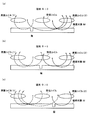
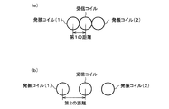
- an oscillation coil (1) (first oscillation coil), a reception coil, and an oscillation coil (2) (second oscillation coil) are disposed at positions facing the inspection object M, for example.
- the test object M is arranged in a line in the extending direction (lateral direction in FIG. 1).
- the oscillation coil (1) and the oscillation coil (2) generate alternating magnetic fields opposite to each other.
- the receiving coil is positioned between the oscillation coil (1) and the oscillation coil (2), and outputs a magnetic field waveform based on the magnetic field received from the oscillation coil (1) and the oscillation coil (2) as inspection data.
- Magnetic field lines B1, B2, B3 generated from the oscillation coil (1) pass through the inspection object M, but leak from the inspection object M and return to the oscillation coil (1). At this time, the magnitudes of the magnetic lines B1, B2, and B3 returning to the oscillation coil (1) depend on the cross-sectional area of the inspection object M and the height h (distance from the inspection object M to the oscillation coil (1)). Further, the closer to the oscillation coil (1), the stronger the magnetic force, so that the magnitude relationship of the magnetic field lines B1, B2, B3 is B1> B2> B3.
- the magnetic field lines B11, B12, B13 generated from the oscillation coil (2) pass through the inspection object M, but leak from the inspection object M and return to the oscillation coil (2). Further, the magnitude relationship of the strengths of the magnetic lines of force B11, B12, and B13 is B11> B12> B13.
- the upward direction in FIG. 1 is the positive direction of the magnetic force. Further, it is assumed that the intensity of the alternating magnetic field generated by the oscillation coil (1) and the oscillation coil (2) is the same. Further, in the following, at a certain moment, the magnetic field generated from the oscillation coil (1) is generated in a direction passing through the inside of the oscillation coil (1) downward, and the magnetic field generated from the oscillation coil (2) passes through the interior of the oscillation coil upward. Consider a case that occurs in a direction.
- the magnetic lines B1 and B13 cancel each other, but the magnetic lines B1 are stronger (B1 + B13> 0), so that upward magnetic lines remain.
- the magnetic force lines B3 and B11 cancel each other, but the magnetic force lines B11 are stronger (B3 + B11 ⁇ 0), so that downward magnetic force lines remain.
- the magnetic flux interlinking with the receiving coil is represented by ⁇ .
- ⁇ the magnetic flux interlinking with the receiving coil.
- FIG. 2 (a) if there is a flaw in the inspection object M between the oscillation coil (1) and the receiving coil, it is generated from the oscillation coil (1) and passes through the inspection object M. Since many of the magnetic field lines protrude upward from the scratch, the magnetic flux ⁇ ⁇ 0.
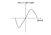
- the relationship between the magnetic flux ⁇ interlinking with the receiving coil and the position of the flaw is approximately as shown in FIG. Therefore, it is possible to identify a deteriorated part such as a flaw in the inspection target M based on the change over time of the current (magnetic field waveform) output from the receiving coil.
- the magnetic field waveform output from the receiving coil varies greatly at the deteriorated portion of the inspection object M (see, for example, FIG. 10A). Therefore, in this way, based on the configuration and principle that the alternating magnetic fields opposite to each other from the oscillation coils (1) and (2) cancel each other at the position of the receiving coil, the inspection object M has a high SN ratio. Inspection data relating to degradation can be generated.
- the sensor output S shown in FIG. 10A is a schematic diagram when the actual sensor output is squared.
- the magnetic flux generated by the oscillating coil (1) and the oscillating coil (2) cancels out at the receiving coil portion. It can be said that the magnetic flux in the receiving coil is close to zero compared to the two cases. Further, the difference in how the magnetic flux changes in the receiving coil differs depending on whether or not the inspection object M has a flaw, and the flaws of the inspection object M can be specified with a high SN ratio using three coils.
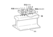
- the detection device 2 (rail inspection device) including three coils is arranged at a position facing the upper surface of the rail RR.
- the detection device 2 is attached to, for example, a bottom portion outside the rail flaw detection vehicle.
- inspection data relating to deterioration is generated by a large fluctuation in the magnetic field waveform output from the receiving coil at the deterioration (scratch) portion of the rail RR. Can do.
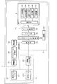
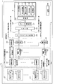
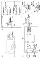
- a rail inspection system 1 that performs an inspection relating to deterioration of a rail for a vehicle includes a detection device 2 and a processing device 3.
- the rail inspection system 1 shown in FIG. 5 is different from the rail inspection system 1a shown in FIG. 7 in that the number of sensor parts 21 is one (one channel) as compared to a plurality of (multi-channel) rail inspection systems 1a. is doing.
- the detection device 2 is a device that generates inspection data relating to deterioration of the rail RR, and includes a sensor unit 21 and an amplification / filter unit 22 and is installed, for example, at the bottom of the rail flaw detection vehicle outside the vehicle.
- the sensor unit 21 is arranged in a line along the extending direction of the rail RR on the surface facing the rail rail RR to be inspected.
- the oscillating coils (1), (2) 211 that generate alternating magnetic fields opposite to each other.
- a reception coil 212 that is located in the middle of or near the oscillation coils (1) and (2) 211 and that outputs a magnetic field waveform based on the magnetic field received from the oscillation coils (1) and (2) 211 as inspection data. (See FIG. 4).
- oscillation coils (1) and (2) 211 correspond to the oscillation coil (1) and the oscillation coil (2) shown in FIG. 4, and hereinafter, the reference numeral “211” may be omitted.
- the receiving coil 212 corresponds to the receiving coil shown in FIG.
- the amplification / filter unit 22 amplifies and filters the output signal received from the receiving coil, and transmits the amplified signal to the detection unit 34 of the processing device 3.
- the processing device 3 includes an amplification unit 31, a digital / analog conversion unit 32, an oscillation unit 33, a detection unit 34, an analog / digital conversion unit 35, a memory unit 36, a data communication unit 37, a power supply 38, and an evaluation device 4, for example. It is installed in the rail flaw detection vehicle.
- the oscillation unit 33 transmits a digital oscillation signal at a predetermined period (for example, 20 kHz).
- the digital-analog conversion unit 32 converts the digital oscillation signal received from the oscillation unit 33 into an analog alternating current.
- the amplifying unit 31 amplifies the alternating current received from the digital / analog converting unit 32, and passes the amplified alternating current through the oscillation coils (1) and (2).
- the oscillation coils (1) and (2) through which the alternating current flows generate alternating magnetic fields opposite to each other.
- the winding directions of the respective coils may be reversed.
- the output signal (magnetic field waveform) output from the receiving coil based on the alternating magnetic field received from the oscillation coils (1) and (2) is amplified and filtered by the amplification / filter unit 22 and input to the detection unit 34.
- the detector 34 performs full-wave rectification processing and filter processing (mainly processing by a low-pass filter (LPF)) using the reference signal from the oscillation unit 33.
- the analog / digital converter 35 converts the analog signal received from the detector 34 into a digital signal.
- the data (digital signal) converted by the analog-digital conversion unit 35 is stored in the memory unit 36 and output from the data communication unit 37 to the evaluation device 4.
- the power supply 38 supplies power to each component in the rail inspection system 1.
- the evaluation device 4 is a computer device that executes an inspection process for identifying a deteriorated portion of the railroad rail based on the inspection data received from the detection device 2.
- the evaluation device 4 includes a data input unit 41, a control unit 42, a data processing unit 43, an output processing unit 44, an operation input unit 45, a display unit 46, and a storage unit 47.
- the inspection data corresponds to data at all stages from the receiving coil of the detection device 2 to the data input unit 41 of the evaluation device 4.
- the data input unit 41 inputs an output signal (inspection data) from the data communication unit 37.
- the control unit 42 is configured by a CPU (Central Processing Unit), a RAM (Random Access Memory), a ROM (Read Only Memory), and the like, and controls data transfer and arithmetic processing.
- the data processing unit 43 performs an inspection process based on the output signal (inspection data) (details will be described later). Information such as inspection results is stored in the storage unit 47 as appropriate.
- the output processing unit 44 performs processing for displaying the inspection result and the like on the display unit 46 in a display format that is easy to visually understand by appropriately using a graph or table format.
- the operation input unit 45 is information input means such as a keyboard and a mouse.
- the display unit 46 is an LCD (Liquid Crystal Display), a CRT (Cathode Ray Tube) display, or the like that displays inspection results.
- the storage unit 47 stores data processed by the data processing unit 43.
- the data processing unit 43 and the output processing unit 44 are realized by loading a program or data stored in the storage unit 47 into the control unit 42 and executing arithmetic processing.
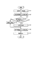
- the data processing unit 43 acquires inspection data from the storage unit 47 (step S1).
- an offset adjustment process for adjusting the offset in the inspection data may be performed.
- the data processing unit 43 repeats the processes of the following steps S3 to S5 every predetermined time width (for example, about 0.5 ms to 100 ms) (steps S2 to S6).
- the data processing unit 43 determines whether or not there is a waveform value out of the reference range for the inspection data having a predetermined time width (step S3), and in the case of No, it is determined to be normal (step S4). Is determined to be abnormal (step S5).
- step S7 When the processing from step S2 to step S6 is completed for the entire inspection data, the data processing unit 43 displays the inspection result on the display unit 46 (step S7).
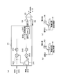
- N (1 to N channel) sensor units 21 are provided in the detection device 2a installed at the bottom of the rail flaw detection vehicle.
- N amplification / filter units 22 of the detection device 2a, N amplification units 31 and detection units 34 of the processing device 3 are also provided.
- the digital / analog conversion unit 32 converts the digital oscillation signal received from the oscillation unit 33 into an analog alternating current and sends the analog alternating current to the N amplification units 31.
- Each of the N amplifying units 31 sends an excitation signal (alternating current) for each channel to the corresponding oscillation coil (1) (2) 211.
- Each reception coil sends a detection signal for each channel (output signal (magnetic field waveform)) to the corresponding detection unit 34 via the amplification / filter unit 22.
- the analog-digital conversion unit 35 converts the measurement signal for each channel (analog signal) received from each detection unit 34 into the collected data (digital signal) for each channel and stores it in the memory unit 36.
- the evaluation device 4 executes an inspection process (the process shown in FIG. 6) for specifying a deteriorated portion of the railroad rail for each collected data (inspection data) for each channel.
- inspection system 1a the deterioration test of the rail RR can be performed with high precision because the sensor part 21 is plural (multi-channel).
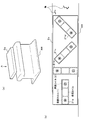
- detection device 2a a specific configuration example of the detection device 2a will be described.
- a detection device 2a including four sensor portions 21a (21) to 21d (21) is disposed at a position facing the upper surface of the rail RR.
- This detection device 2a is attached to the bottom of the rail flaw detection vehicle outside the vehicle, for example.
- the sensor unit 21a is arranged in parallel with the extending direction of the rail RR.
- the sensor unit 21b is disposed perpendicular to the extending direction of the rail RR.
- the sensor unit 21c is disposed at an angle of 45 degrees with respect to the extending direction of the rail RR.
- the sensor unit 21d is disposed at an oblique angle of 45 degrees with respect to the extending direction of the rail RR.
- the detection device 2a even if the sensor portions 21a to 21d whose widths are smaller than the width of the rail RR are used, they are arranged in different directions as shown in FIG. Any width direction position and shape flaw can be detected with high accuracy.
- the number and arrangement state of the plurality of sensor units 21 are not limited to the number (4 pieces) and arrangement state (FIG. 8B) of the sensor units 21a to 21d.
- the detection device 2b is arranged in parallel in the width direction of the railway rail RR with a large oscillation coil (1) and oscillation coil (2) that cover the width of the railway rail RR. N independent receive coils.
- This detection device 2b is attached to the bottom of the rail flaw detection vehicle outside the vehicle, for example.
- the configuration of the rail inspection system is one set of the oscillation coil (1) and the oscillation coil (2) as compared with the rail inspection system 1a shown in FIG. The difference is that the number is one, but the others are the same, and the illustration is omitted.
- the detection device 2b shown in FIGS. 9 (a) and 9 (b) When the detection device 2b shown in FIGS. 9 (a) and 9 (b) is used, if there is a scratch on the rail RR, the receiving coil corresponding to the position in the width direction of the rail on the rail RR will generate an output signal due to the scratch. to be influenced. Thereby, it is possible to detect with high accuracy any width direction position on the rail RR and to specify the width direction position. Further, since only one oscillation coil (1), one oscillation coil (2), and one amplifying unit 31 are required, the circuit scale can be reduced, and power saving, low cost, and downsizing can be realized.
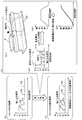
- FIGS. 10 to 14 correspond to the rail inspection system 1 shown in FIG. 5, the rail inspection system 1a shown in FIG. 7, the detection device 2a in FIG. 8, and the detection device 2b in FIG. This is common to all rail inspection systems.
- the output signal from the receiving coil is displayed in a graph with the sensor output S as the vertical axis and the measurement time (measurement time) T as the horizontal axis, for example, as shown in FIG.
- P1 to P5 are signals due to scratches.
- the position of the scratch in the rail extension direction is not known.
- the rail RR generally has joints at regular intervals (L) for convenience of manufacturing and the like.
- the rail extension direction position of this joint is known.
- P11 and P15 which are sensor outputs S by the joints are significantly larger than P12 to P14 which are sensor outputs S by the flaws.
- the time from P11 to P15 is TL .
- the relationship between the train (rail flaw detection vehicle) speed V and the measurement time T can be found by using L and TL . Further, as shown in FIG. 10B4, if the relationship is integrated, the relationship between the movement distance A and the measurement time T can be obtained.
- the rail extension direction position of the rail of the rail RR can be specified.
- the waveform is different only in the portion corresponding to the scratch, and the waveform in the other portions is the same.
- the part of the flaw is specified from the sensor output S using the property of.
- the signal X is a component (Cos component) synchronized with the excitation magnetic field (magnetic field excited by the oscillation coils (1) and (2)) in the input signal (reception coil output).
- the phase difference is 0 °.
- the phase comparator 342 receives the reception coil output and the 0 ° phase information from the component decomposer 341 that has received the oscillation output, and outputs a Cos component in the reception coil output.
- the output passes through the low-pass filter circuit 344 and is input to the gain adjusting unit 51 and the arithmetic circuit 346 as the signal X.
- the signal Y is a component (Sin component, phase difference 90 °) that is 90 ° phase shifted with respect to the excitation magnetic field in the input signal (receiver coil output).
- the phase comparator 343 receives the reception coil output and the 90 ° phase information from the component decomposer 341 that has received the oscillation output, and outputs the Sin component in the reception coil output.
- the output passes through the low-pass filter circuit 345 and is input to the arithmetic circuit 346 as the signal Y.
- the signal R generated by the arithmetic circuit 346 is input to the gain adjustment unit 52.
- FIGS. 12A to 12C correspond to FIGS. 11C to 11E.
- the signal X and the signal R are compared.
- the signal X and the signal ⁇ are compared.
- descriptions overlapping with those in FIG. 11 are omitted as appropriate.
- the signal ⁇ represents the phase difference of the input signal with respect to the reference signal (output from the oscillating unit 33 in FIGS. 5 and 7), and is generated by the arithmetic circuit 347 to which the signal X and the signal Y are input.
- the signal ⁇ generated by the arithmetic circuit 347 is input to the gain adjustment unit 54. Further, the signal X is input to the gain adjusting unit 55.
- the waveforms are different only in the portion corresponding to the scratch (reference numeral 63, Reference numeral 64) and the other waveforms are the same. Since the scales of the signal X and the signal ⁇ are different, the gain adjustment unit 54 and the gain adjustment unit 55 perform gain adjustment so that the scales match.
- a differential signal (X ⁇ ) is generated by the differential unit 56 based on the signal X and the signal ⁇ after gain adjustment, only the portion corresponding to the flaw is greatly deviated from zero, so that the flaw can be specified. it can.
- the inter-coil distance refers to the distance from the center of the oscillation coil (1) (or the oscillation coil (2)) to the center of the reception coil.
- the sensor unit for detecting the deterioration of the rail surface sets the distance between the coils as the first distance. Since the first distance varies depending on the distance between the sensor unit and the rail RR, the material of the rail RR, the cross-sectional shape, and the like, it can be obtained by experiments.
- the sensor unit for detecting the deterioration inside the rail sets the inter-coil distance to a second distance larger than the first distance. This second distance can also be obtained by experiment.
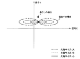
- the locus based on the signal X and the signal Y is displayed on the coordinate plane.
- the locus becomes a point.
- the trajectory is, for example, a figure of 8. The larger the 8-shaped trajectory, the larger the flaw size. Therefore, a person who sees this display can easily grasp the flaw size.
- the sensor in which the oscillation coil (1), the reception coil, and the oscillation coil (2) are arranged in this order on the surface facing the rail to be inspected.
- the unit 21 to generate AC magnetic fields in opposite directions from the oscillation coils (1) and (2) and outputting the magnetic field waveform from the reception coil as inspection data, the deterioration of the rail for the vehicle can be achieved with a high SN ratio. Can be inspected.
- the evaluation device 4 can identify the deteriorated portion of the rail RR by executing the inspection process based on the inspection data received from the detection device 2.
- other configurations, operational effects, and the like according to the present embodiment are as described above.
- the oblique angle of the sensor unit 21c in FIG. 8 with respect to the extending direction of the rail RR may be other angles such as 30 degrees instead of 45 degrees.
- the sensor unit 21d in FIG. can change suitably in the range which does not deviate from the main point of this invention.
Landscapes
- Chemical & Material Sciences (AREA)
- Chemical Kinetics & Catalysis (AREA)
- Electrochemistry (AREA)
- Physics & Mathematics (AREA)
- Health & Medical Sciences (AREA)
- Life Sciences & Earth Sciences (AREA)
- Analytical Chemistry (AREA)
- Biochemistry (AREA)
- General Health & Medical Sciences (AREA)
- General Physics & Mathematics (AREA)
- Immunology (AREA)
- Pathology (AREA)
- Engineering & Computer Science (AREA)
- Mechanical Engineering (AREA)
- Investigating Or Analyzing Materials By The Use Of Magnetic Means (AREA)
Priority Applications (2)
| Application Number | Priority Date | Filing Date | Title |
|---|---|---|---|
| US15/740,020 US10591442B2 (en) | 2015-07-09 | 2016-03-11 | Rail check device and rail check system |
| EP16821060.7A EP3321671B1 (en) | 2015-07-09 | 2016-03-11 | Rail inspection device and rail inspection system |
Applications Claiming Priority (2)
| Application Number | Priority Date | Filing Date | Title |
|---|---|---|---|
| JP2015-137823 | 2015-07-09 | ||
| JP2015137823A JP6506122B2 (ja) | 2015-07-09 | 2015-07-09 | レール検査装置、および、レール検査システム |
Publications (1)
| Publication Number | Publication Date |
|---|---|
| WO2017006589A1 true WO2017006589A1 (ja) | 2017-01-12 |
Family
ID=57684969
Family Applications (1)
| Application Number | Title | Priority Date | Filing Date |
|---|---|---|---|
| PCT/JP2016/057801 Ceased WO2017006589A1 (ja) | 2015-07-09 | 2016-03-11 | レール検査装置、および、レール検査システム |
Country Status (4)
| Country | Link |
|---|---|
| US (1) | US10591442B2 (enExample) |
| EP (1) | EP3321671B1 (enExample) |
| JP (1) | JP6506122B2 (enExample) |
| WO (1) | WO2017006589A1 (enExample) |
Cited By (3)
| Publication number | Priority date | Publication date | Assignee | Title |
|---|---|---|---|---|
| WO2018003460A1 (ja) * | 2016-06-28 | 2018-01-04 | 株式会社日立ハイテクファインシステムズ | レール検査システム |
| JP2018100942A (ja) * | 2016-12-21 | 2018-06-28 | 株式会社日立ハイテクファインシステムズ | レール検査システム |
| WO2019196998A1 (en) * | 2018-04-09 | 2019-10-17 | Københavns Universitet | An eddy-current detector and a method for calibrating such an eddy-current detector |
Families Citing this family (14)
| Publication number | Priority date | Publication date | Assignee | Title |
|---|---|---|---|---|
| US9849895B2 (en) | 2015-01-19 | 2017-12-26 | Tetra Tech, Inc. | Sensor synchronization apparatus and method |
| US10349491B2 (en) | 2015-01-19 | 2019-07-09 | Tetra Tech, Inc. | Light emission power control apparatus and method |
| CA2892952C (en) | 2015-01-19 | 2019-10-15 | Tetra Tech, Inc. | Protective shroud |
| CA2892885C (en) | 2015-02-20 | 2020-07-28 | Tetra Tech, Inc. | 3d track assessment system and method |
| US11377130B2 (en) | 2018-06-01 | 2022-07-05 | Tetra Tech, Inc. | Autonomous track assessment system |
| US10625760B2 (en) | 2018-06-01 | 2020-04-21 | Tetra Tech, Inc. | Apparatus and method for calculating wooden crosstie plate cut measurements and rail seat abrasion measurements based on rail head height |
| US10807623B2 (en) | 2018-06-01 | 2020-10-20 | Tetra Tech, Inc. | Apparatus and method for gathering data from sensors oriented at an oblique angle relative to a railway track |
| AU2020273465C8 (en) | 2019-05-16 | 2025-11-13 | Tetra Tech, Inc. | System and method for generating and interpreting point clouds of a rail corridor along a survey path |
| CN113970709A (zh) * | 2021-10-27 | 2022-01-25 | 徐州中矿传动轨道科技有限公司 | 一种地铁钢轨对地局部绝缘损坏点定位方法及系统 |
| JP2023181824A (ja) * | 2022-06-13 | 2023-12-25 | 株式会社日立製作所 | レール状態監視装置およびレール状態監視方法 |
| DE102023210255A1 (de) | 2023-10-19 | 2025-04-24 | Robert Bosch Gesellschaft mit beschränkter Haftung | Verfahren zum Erkennen von Schäden/Defekten einer mittels eines Schienenfahrzeugs befahrenen Schiene eines Gleises basierend auf Magnetfelddaten |
| DE102023210254A1 (de) | 2023-10-19 | 2025-04-24 | Robert Bosch Gesellschaft mit beschränkter Haftung | Verfahren zum Erkennen von fehlerhaften Schienenelementen eines Gleises basierend auf Magnetfelddaten |
| DE102023210253A1 (de) | 2023-10-19 | 2025-04-24 | Robert Bosch Gesellschaft mit beschränkter Haftung | Verfahren zum Erkennen einer oder mehrerer fehlender Schwellenklammern einer mittels eines Schienenfahrzeugs befahrenen Schiene eines Gleises basierend auf Magnetfelddaten |
| BE1032468B1 (de) * | 2024-03-14 | 2025-10-13 | Rosenxt Holding Ag | Inspektionsvorrichtung für Betonspannelemente |
Citations (11)
| Publication number | Priority date | Publication date | Assignee | Title |
|---|---|---|---|---|
| JPH08101168A (ja) * | 1994-09-30 | 1996-04-16 | Tokyo Gas Co Ltd | 導管検査用ピグの走行監視システム |
| JP2001108659A (ja) * | 1999-10-07 | 2001-04-20 | Amikku:Kk | 金属表面探傷用渦流プローブ |
| JP2003050234A (ja) * | 2001-08-07 | 2003-02-21 | Marktec Corp | 渦流探傷試験装置 |
| JP2003270214A (ja) * | 2002-03-15 | 2003-09-25 | ▲高▼木 敏行 | 渦電流探傷法及び探傷プローブ |
| JP2004279372A (ja) * | 2003-03-19 | 2004-10-07 | Yazaki Corp | 破断検出方法 |
| JP2004279055A (ja) * | 2003-03-12 | 2004-10-07 | Sumitomo Metal Ind Ltd | 鋼管内面の浸炭深さ測定方法及び装置 |
| JP2006220526A (ja) * | 2005-02-10 | 2006-08-24 | Jfe Steel Kk | 表層部性状測定方法及びそれを用いた表層欠陥判定方法、並びに金属帯の製造方法 |
| WO2013024858A1 (ja) * | 2011-08-18 | 2013-02-21 | 新日鐵住金株式会社 | 磁気探傷方法及び磁気探傷装置 |
| JP2013185951A (ja) * | 2012-03-08 | 2013-09-19 | Jfe Steel Corp | 電磁気探傷用プローブ |
| JP2014044151A (ja) * | 2012-08-28 | 2014-03-13 | N D R Kk | 欠陥検出装置 |
| JP2014102197A (ja) * | 2012-11-21 | 2014-06-05 | Meielec:Kk | 磁気誘導式レール探傷方法及び磁気誘導式レール探傷装置 |
Family Cites Families (19)
| Publication number | Priority date | Publication date | Assignee | Title |
|---|---|---|---|---|
| US2203256A (en) * | 1938-12-15 | 1940-06-04 | Sperry Prod Inc | Rail flaw detector mechanism |
| US2622131A (en) * | 1945-11-13 | 1952-12-16 | Teledetector Inc | Portable rail flaw detector |
| US2602840A (en) * | 1947-05-20 | 1952-07-08 | Teledetector Inc | Electromagnet for rail fissure detectors |
| US2682442A (en) * | 1948-07-23 | 1954-06-29 | Frank H Keaton | Indicating means for rail flaw detecting apparatus |
| US2671197A (en) * | 1950-09-02 | 1954-03-02 | Walter C Barnes | Magnetizing means for rail flaw detector systems |
| US2766424A (en) * | 1951-11-15 | 1956-10-09 | Teleweld Inc | Method and apparatus for detecting fissures in rail |
| US2869073A (en) * | 1953-03-09 | 1959-01-13 | Teleweld Inc | Method and apparatus for distinguishing harmless surface flaws from dangerous fissures in magnetizable bodies |
| US3271662A (en) * | 1962-08-22 | 1966-09-06 | Api Instr Company | Flaw detecting apparatus having multiple pick-up and exciting coils on the same side of the test piece |
| JPS63235854A (ja) | 1987-03-24 | 1988-09-30 | Sumitomo Metal Ind Ltd | 探傷装置 |
| US5623244A (en) * | 1996-05-10 | 1997-04-22 | The United States Of America As Represented By The Secretary Of The Navy | Pilot vehicle which is useful for monitoring hazardous conditions on railroad tracks |
| US5786750A (en) * | 1996-05-10 | 1998-07-28 | The United States Of America As Represented By The Secretary Of The Navy | Pilot vehicle which is useful for monitoring hazardous conditions on railroad tracks |
| AU2001288433A1 (en) * | 2000-08-25 | 2002-03-04 | Em-Tech Llc | Detection of anomalies on railroad tracks |
| EP1436604B1 (en) * | 2001-10-17 | 2015-09-09 | GE Oil & Gas UK Limited | Method for measuring material properties and lift-off components of an object using a magnetic probe |
| US8049494B2 (en) * | 2007-05-21 | 2011-11-01 | Olympus Ndt | Flexible array probe for the inspection of a contoured surface with varying cross-sectional geometry |
| WO2009083996A2 (en) * | 2007-12-31 | 2009-07-09 | General Electric Company | Method for compensation of responses from eddy current probes |
| JP4863127B2 (ja) | 2008-05-15 | 2012-01-25 | 住友金属工業株式会社 | 磁気探傷方法及び磁気探傷装置 |
| US20130024135A1 (en) * | 2011-07-22 | 2013-01-24 | Blum Dieter W | Method And Apparatus For Ferromagnetic Cable Inspection |
| JP2014066688A (ja) | 2012-09-27 | 2014-04-17 | Hosei Univ | 渦流探傷プローブ、渦流探傷装置 |
| US9669851B2 (en) * | 2012-11-21 | 2017-06-06 | General Electric Company | Route examination system and method |
-
2015
- 2015-07-09 JP JP2015137823A patent/JP6506122B2/ja active Active
-
2016
- 2016-03-11 EP EP16821060.7A patent/EP3321671B1/en active Active
- 2016-03-11 US US15/740,020 patent/US10591442B2/en active Active
- 2016-03-11 WO PCT/JP2016/057801 patent/WO2017006589A1/ja not_active Ceased
Patent Citations (11)
| Publication number | Priority date | Publication date | Assignee | Title |
|---|---|---|---|---|
| JPH08101168A (ja) * | 1994-09-30 | 1996-04-16 | Tokyo Gas Co Ltd | 導管検査用ピグの走行監視システム |
| JP2001108659A (ja) * | 1999-10-07 | 2001-04-20 | Amikku:Kk | 金属表面探傷用渦流プローブ |
| JP2003050234A (ja) * | 2001-08-07 | 2003-02-21 | Marktec Corp | 渦流探傷試験装置 |
| JP2003270214A (ja) * | 2002-03-15 | 2003-09-25 | ▲高▼木 敏行 | 渦電流探傷法及び探傷プローブ |
| JP2004279055A (ja) * | 2003-03-12 | 2004-10-07 | Sumitomo Metal Ind Ltd | 鋼管内面の浸炭深さ測定方法及び装置 |
| JP2004279372A (ja) * | 2003-03-19 | 2004-10-07 | Yazaki Corp | 破断検出方法 |
| JP2006220526A (ja) * | 2005-02-10 | 2006-08-24 | Jfe Steel Kk | 表層部性状測定方法及びそれを用いた表層欠陥判定方法、並びに金属帯の製造方法 |
| WO2013024858A1 (ja) * | 2011-08-18 | 2013-02-21 | 新日鐵住金株式会社 | 磁気探傷方法及び磁気探傷装置 |
| JP2013185951A (ja) * | 2012-03-08 | 2013-09-19 | Jfe Steel Corp | 電磁気探傷用プローブ |
| JP2014044151A (ja) * | 2012-08-28 | 2014-03-13 | N D R Kk | 欠陥検出装置 |
| JP2014102197A (ja) * | 2012-11-21 | 2014-06-05 | Meielec:Kk | 磁気誘導式レール探傷方法及び磁気誘導式レール探傷装置 |
Cited By (6)
| Publication number | Priority date | Publication date | Assignee | Title |
|---|---|---|---|---|
| WO2018003460A1 (ja) * | 2016-06-28 | 2018-01-04 | 株式会社日立ハイテクファインシステムズ | レール検査システム |
| US10739311B2 (en) | 2016-06-28 | 2020-08-11 | Hitachi High-Tech Fine Systems Corporation | Rail inspection system |
| JP2018100942A (ja) * | 2016-12-21 | 2018-06-28 | 株式会社日立ハイテクファインシステムズ | レール検査システム |
| WO2018116546A1 (ja) * | 2016-12-21 | 2018-06-28 | 株式会社日立ハイテクファインシステムズ | レール検査システム |
| US10989694B2 (en) | 2016-12-21 | 2021-04-27 | Hitachi High-Tech Fine Systems Corporation | Rail inspection system |
| WO2019196998A1 (en) * | 2018-04-09 | 2019-10-17 | Københavns Universitet | An eddy-current detector and a method for calibrating such an eddy-current detector |
Also Published As
| Publication number | Publication date |
|---|---|
| US20180172639A1 (en) | 2018-06-21 |
| EP3321671A1 (en) | 2018-05-16 |
| EP3321671B1 (en) | 2023-11-29 |
| EP3321671A4 (en) | 2019-01-09 |
| JP6506122B2 (ja) | 2019-04-24 |
| JP2017020862A (ja) | 2017-01-26 |
| US10591442B2 (en) | 2020-03-17 |
Similar Documents
| Publication | Publication Date | Title |
|---|---|---|
| WO2017006589A1 (ja) | レール検査装置、および、レール検査システム | |
| JP6768486B2 (ja) | レール検査システム | |
| US11358836B2 (en) | Wire rope inspection device, wire rope inspection system, and wire rope inspection method | |
| US20090102473A1 (en) | Eddy current testing method and eddy current testing apparatus | |
| JP6211166B2 (ja) | ハンドレール検査装置、および、ハンドレール検査システム | |
| JP6594065B2 (ja) | ロープ検査装置、および、ロープ検査システム | |
| JP7200697B2 (ja) | ワイヤロープ検査装置およびワイヤロープ検査方法 | |
| CN116075719A (zh) | 钢丝绳检查装置和钢丝绳检查系统 | |
| US10739311B2 (en) | Rail inspection system | |
| WO2019044018A1 (ja) | 非破壊検査装置 | |
| JP2016173340A (ja) | 配管検査装置 | |
| JP2016057225A (ja) | 渦電流探傷センサ装置 | |
| EP3159854B1 (en) | Coin detection system | |
| JP2010048552A (ja) | 非破壊検査装置及び非破壊検査方法 | |
| KR101988887B1 (ko) | 자기 센서 배열을 이용한 리사주선도 도시 장치 | |
| JP6882117B2 (ja) | 励磁コイル、非破壊検査装置、及び非破壊検査方法 | |
| JP2010281762A (ja) | 非破壊検査装置および非破壊検査方法 | |
| JP2015078942A (ja) | 漏洩磁束探傷装置 | |
| Crouch et al. | Development of nonlinear harmonic sensors for detection of mechanical damage | |
| WO2022230032A1 (ja) | コイルセット | |
| JP2007155429A (ja) | コンクリート構造物の検査方法および検査装置 | |
| JP2021001813A (ja) | 非破壊検査用磁気センサ及び非破壊検査装置 | |
| JPH04268449A (ja) | 電磁気探傷方法 | |
| JP2015059881A (ja) | 渦電流探傷方法と渦電流探傷装置 | |
| JPH0736056U (ja) | 方向感知型渦電流探傷装置 |
Legal Events
| Date | Code | Title | Description |
|---|---|---|---|
| 121 | Ep: the epo has been informed by wipo that ep was designated in this application |
Ref document number: 16821060 Country of ref document: EP Kind code of ref document: A1 |
|
| WWE | Wipo information: entry into national phase |
Ref document number: 15740020 Country of ref document: US |
|
| NENP | Non-entry into the national phase |
Ref country code: DE |
|
| WWE | Wipo information: entry into national phase |
Ref document number: 2016821060 Country of ref document: EP |