EP3321671B1 - Rail inspection device and rail inspection system - Google Patents
Rail inspection device and rail inspection system Download PDFInfo
- Publication number
- EP3321671B1 EP3321671B1 EP16821060.7A EP16821060A EP3321671B1 EP 3321671 B1 EP3321671 B1 EP 3321671B1 EP 16821060 A EP16821060 A EP 16821060A EP 3321671 B1 EP3321671 B1 EP 3321671B1
- Authority
- EP
- European Patent Office
- Prior art keywords
- rail
- check
- oscillation
- coil
- check data
- Prior art date
- Legal status (The legal status is an assumption and is not a legal conclusion. Google has not performed a legal analysis and makes no representation as to the accuracy of the status listed.)
- Active
Links
Images


Classifications
-
- G—PHYSICS
- G01—MEASURING; TESTING
- G01N—INVESTIGATING OR ANALYSING MATERIALS BY DETERMINING THEIR CHEMICAL OR PHYSICAL PROPERTIES
- G01N27/00—Investigating or analysing materials by the use of electric, electrochemical, or magnetic means
- G01N27/72—Investigating or analysing materials by the use of electric, electrochemical, or magnetic means by investigating magnetic variables
- G01N27/82—Investigating or analysing materials by the use of electric, electrochemical, or magnetic means by investigating magnetic variables for investigating the presence of flaws
- G01N27/90—Investigating or analysing materials by the use of electric, electrochemical, or magnetic means by investigating magnetic variables for investigating the presence of flaws using eddy currents
- G01N27/904—Investigating or analysing materials by the use of electric, electrochemical, or magnetic means by investigating magnetic variables for investigating the presence of flaws using eddy currents with two or more sensors
-
- B—PERFORMING OPERATIONS; TRANSPORTING
- B61—RAILWAYS
- B61K—AUXILIARY EQUIPMENT SPECIALLY ADAPTED FOR RAILWAYS, NOT OTHERWISE PROVIDED FOR
- B61K9/00—Railway vehicle profile gauges; Detecting or indicating overheating of components; Apparatus on locomotives or cars to indicate bad track sections; General design of track recording vehicles
- B61K9/08—Measuring installations for surveying permanent way
- B61K9/10—Measuring installations for surveying permanent way for detecting cracks in rails or welds thereof
-
- B—PERFORMING OPERATIONS; TRANSPORTING
- B61—RAILWAYS
- B61L—GUIDING RAILWAY TRAFFIC; ENSURING THE SAFETY OF RAILWAY TRAFFIC
- B61L23/00—Control, warning or like safety means along the route or between vehicles or trains
- B61L23/04—Control, warning or like safety means along the route or between vehicles or trains for monitoring the mechanical state of the route
- B61L23/042—Track changes detection
- B61L23/044—Broken rails
-
- G—PHYSICS
- G01—MEASURING; TESTING
- G01N—INVESTIGATING OR ANALYSING MATERIALS BY DETERMINING THEIR CHEMICAL OR PHYSICAL PROPERTIES
- G01N27/00—Investigating or analysing materials by the use of electric, electrochemical, or magnetic means
- G01N27/72—Investigating or analysing materials by the use of electric, electrochemical, or magnetic means by investigating magnetic variables
- G01N27/82—Investigating or analysing materials by the use of electric, electrochemical, or magnetic means by investigating magnetic variables for investigating the presence of flaws
- G01N27/83—Investigating or analysing materials by the use of electric, electrochemical, or magnetic means by investigating magnetic variables for investigating the presence of flaws by investigating stray magnetic fields
-
- G—PHYSICS
- G01—MEASURING; TESTING
- G01N—INVESTIGATING OR ANALYSING MATERIALS BY DETERMINING THEIR CHEMICAL OR PHYSICAL PROPERTIES
- G01N27/00—Investigating or analysing materials by the use of electric, electrochemical, or magnetic means
- G01N27/72—Investigating or analysing materials by the use of electric, electrochemical, or magnetic means by investigating magnetic variables
- G01N27/82—Investigating or analysing materials by the use of electric, electrochemical, or magnetic means by investigating magnetic variables for investigating the presence of flaws
- G01N27/90—Investigating or analysing materials by the use of electric, electrochemical, or magnetic means by investigating magnetic variables for investigating the presence of flaws using eddy currents
- G01N27/9006—Details, e.g. in the structure or functioning of sensors
-
- G—PHYSICS
- G01—MEASURING; TESTING
- G01N—INVESTIGATING OR ANALYSING MATERIALS BY DETERMINING THEIR CHEMICAL OR PHYSICAL PROPERTIES
- G01N27/00—Investigating or analysing materials by the use of electric, electrochemical, or magnetic means
- G01N27/72—Investigating or analysing materials by the use of electric, electrochemical, or magnetic means by investigating magnetic variables
- G01N27/82—Investigating or analysing materials by the use of electric, electrochemical, or magnetic means by investigating magnetic variables for investigating the presence of flaws
- G01N27/90—Investigating or analysing materials by the use of electric, electrochemical, or magnetic means by investigating magnetic variables for investigating the presence of flaws using eddy currents
- G01N27/9013—Arrangements for scanning
- G01N27/902—Arrangements for scanning by moving the sensors
-
- G—PHYSICS
- G01—MEASURING; TESTING
- G01N—INVESTIGATING OR ANALYSING MATERIALS BY DETERMINING THEIR CHEMICAL OR PHYSICAL PROPERTIES
- G01N27/00—Investigating or analysing materials by the use of electric, electrochemical, or magnetic means
- G01N27/72—Investigating or analysing materials by the use of electric, electrochemical, or magnetic means by investigating magnetic variables
- G01N27/82—Investigating or analysing materials by the use of electric, electrochemical, or magnetic means by investigating magnetic variables for investigating the presence of flaws
- G01N27/90—Investigating or analysing materials by the use of electric, electrochemical, or magnetic means by investigating magnetic variables for investigating the presence of flaws using eddy currents
- G01N27/9046—Investigating or analysing materials by the use of electric, electrochemical, or magnetic means by investigating magnetic variables for investigating the presence of flaws using eddy currents by analysing electrical signals
- G01N27/9053—Compensating for probe to workpiece spacing
Definitions
- the present invention relates to a technology with which a defect on a rail used for vehicles such as railway cars is checked.
- Patent Document 1 There is a modified flaw checking method disclosed in the Patent document 1. According to this modified flaw checking method, while an alternating current magnetic field generated from an excited coil is being applied to a railway rail to generate an eddy current, a flaw of the railway rail is detected based on an amplitude change of a varying induced voltage that is induced by the eddy current and detected through a couple of detection coils disposed on both sides of the magnetically exciting coil the railway rail.
- Patent Document 2 discloses an eddy current flaw detection probe including a first exciting coil, a second exciting coil and a detection coil disposed between the first exciting coil and the second exciting coil.
- Patent Document 3 a first coil pair consisting of two adjacent coils has the same direction as the generated magnetic field, and the second coil pair consisting of two adjacent coils has the opposite direction of the generated magnetic field.
- Patent Document 4 shows a breaking detection device having a pair of magnets arranged with their opposed magnetic poles different in polarity and a magnetic field sensor arranged at a position where the influences of two opposed magnetic fields generated by the pair of magnets are balanced.
- Patent Document 5 an opposing field sensing element for ferromagnetic cable inspection is disclosed that uses magnetic flux sources and a magnetic flux sensor to detect anomalies in ferromagnetic cables.
- the objective of the present invention is to enable checking on the defect of the railway rail at a higher SN ratio.
- the present invention enables checking a rail for vehicles with a high S/N ratio.
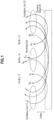
- a principle of how check data on a defect on a checked object M is obtained with a couple of oscillation coils and one receiving coil (referred to as "three coils" hereinafter).
- this embodiment has an oscillation coil (1) (First oscillation coil), a receiving coil and an oscillation coil (2) (Second oscillation coil), all of which are disposed opposite a checked object M and, for example, aligned in a longitudinal direction of the checked object M (lateral direction of Fig.1 ).
- the oscillation coil (1) and the oscillation coil (2) are configured to generate alternating current magnetic fields whose directions are opposite to each other.
- the receiving coil is disposed between the oscillation coil (1) and the oscillation coil (2) and outputs a magnetic field waveform according to magnetic fields received from the oscillation coil (1) and the oscillation coil (2).
- Magnetic field lines B1, B2, B3 generated from the oscillation coil (1) run through the checked object M, leak out of the object M and come back through the oscillation coil (1). Sizes of the magnetic field lines coming back through the oscillation coil (1) are dependent on the cross section and the height h (distance from the checked object M to the oscillation coil (1)) of the checked object M. In addition, the closer a point is to the oscillation coil (1), the stronger the magnetic field at the point. Therefore, the magnetic field lines have a magnitude relation of their magnetic fields of B3 ⁇ B2 ⁇ B1.
- magnetic field lines B11, B12, B13 generated from the oscillation coil (2) run through the checked object M, leak out of the checked object M and come back through the oscillation coil (2).
- the magnetic field lines B11, B12, B13 have a magnitude relation of their magnetic fields of B13 ⁇ B12 ⁇ B11.
- an upper direction is assumed to be a positive direction of the magnetic field
- the oscillation coil (1) and the oscillation coil (2) are assumed to generate the alternating current magnetic fields that are equal to each other.
- the following case is considered. That is, at a certain moment a magnetic field that comes into the oscillation coil (1) from an upper side thereof and runs through the oscillation coil (1) is generated from the oscillation coil (1) and simultaneously the other magnetic field that comes into the oscillation coil (2) from a lower side thereof and runs through the oscillation coil (2) is generated from the oscillation coil (2).
- the magnetic field line B1 and the magnetic field line B13 offset each other and the magnetic field line B1 is stronger at the positions. Accordingly there remains a magnetic field line directed upward (B1 + B13 > 0).
- interlinkage flux that interlinks with the receiving coil is represented by ⁇ .
- the position of the defect on the checked object M based on how the current outputted from the receiving coil (magnetic field waveform) changes over time. That is, if the checked object M has a defect, the magnetic field waveform outputted from the receiving coil changes greatly (for example, see Fig.10A ). As has been explained, based on the configuration in which the alternating current magnetic fields generated from the oscillation coil (1) and the oscillation coil (2), whose directions are opposite to each other, offset each other at a position of the receiving coil, it is possible to obtain check data for locating a defect on or in the checked object M with a higher SN ratio.
- the interlinkage flux ⁇ through the receiving coil is not 0 even for the checked object M without a defect (no flaw is included) when the receiving coil is offset in the direction of either of the oscillation coil (1) and the oscillation coil (2) from the center between the oscillation coil (1) and the oscillation coil (2).
- the receiving coil does not necessarily have to be disposed at the exact center between the oscillation coil (1) and the oscillation coil (2) and may be disposed in the vicinity of the center between the oscillation coil (1) and the oscillation coil (2).
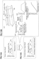
- Fig.10A schematically shows sensor outputs S which correspond to squared actual output values.
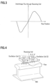
- a detection device inclusive of the three coils is disposed at a position opposite the upper face of the railway rail.
- a detection device 2 (rail check device) inclusive of the three coils is disposed opposite the upper face of the railway rail RR as shown in Fig.4 .
- This detection device 2 is, for example, secured onto the bottom of and outside the rail flaw checking car.
- check data for the defect is obtained according to the change in the magnetic waveform outputted from the receiving coil at a position where there is a flaw.
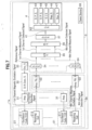
- a rail check system 1 for checking on the defect of the railway rail comprises the detection device 2 and a signal processing device 3.
- the rail check system 1 as indicated in Fig. 5 is different from a rail check system 1a having plural sensor sections 21 (multi-channel) as indicated in Fig.7 , since the rail check system 1 has only one sensor section 21 (one channel)..
- the detection device 2 is a device for obtaining check data for a defect of the railway rail RR, comprises a sensor section 21 and an amplification and filtering section 22 and is, for example, secured on the bottom of the rail flaw checking car and on the outer side of the rail flaw checking car.
- the sensor section 21 comprises a oscillation coil (1) 211 and an oscillation coil (2) 211 which are disposed on a plane opposite the railway rail RR, aligned along the direction in which the railway rail extends and generate alternating current magnetic fields whose directions are opposite to each other, and a receiving coil which is disposed between or in the vicinity of the oscillation coil (1) 211 and the oscillation coil (2) 211 and outputs a magnetic waveform as the check data based on the magnetic fields from the oscillation coil (1) 211 and the oscillation coil (2) 211 (See Fig.4 ).
- the oscillation coils (1) 211, (2)211 correspond respectively to the oscillation coil (1) and the oscillation coil (2) which are shown in Fig.4 . There might be a case where the sign of "211" is skipped below.
- the receiving coil 212 corresponds to the receiving coil as shown in Fig.4 . There might be a case where the sign of "212" is skipped in the explanation below.
- the amplification and filtering section 22 is configured to amplify and filter a signal received from the receiving coil and transmit the amplified and filtered signal to a signal detection section 34.
- the signal processing device 3 comprises an amplification section 31, a digital/analogue conversion section 32, an oscillation section 33, a signal detection section 34, an analogue/digital conversion section 35, a memory section 36, a data communication section 37, a power source section 38 and an evaluation device 4 and installed, for example, in the rail flaw checking car.
- the oscillation section 33 is configured to transmit digital oscillation signals at a predetermined frequency (for example, 20kHz).
- the digital/analogue conversion section 32 is configured to convert the digital oscillation signal received from the oscillation section 33 to an analogue alternating current.
- the amplification section 31 is configured to amplify the alternating current received from the digital/analogue conversion section 32 and have the amplified alternating current flow through the oscillation coils (1), (2).
- the oscillation coils (1), (2) through both of which the alternating currents flow, generate magnetic fields whose directions are opposite to each other.
- One way to have the oscillation coils (1), (2) generate the magnetic fields whose directions are opposite to each other is to have the oscillation coils (1), (2) wound in opposite directions to each other.
- Output signals (magnetic field waveform) outputted from the receiving coil in accordance with the magnetic fields generated by the oscillation coils (1), (2) and coming into the receiving coil are amplified and filtered through the amplification and filtering section 22 and inputted to the signal detection section 34.
- the signal detection section 34 is configured to perform a full-wave rectification process and a filtering process (mainly low-pass filter process) using a reference signal received from the oscillation section 33.
- the analogue/digital conversion section 35 converts the analogue signal received from the signal detection section 34 to a digital signal.
- Data (digital signal) after the conversion by the analogue/digital conversion section 35 is stored on the memory section 36 and outputted from the data communication section 37 to the evaluation device 4.
- the power source 38 supplies power to each section in the rail check system 1.
- the evaluation device 4 is a computer device to perform a checking process to locate a defect on the railway rail based on the check data received from the detection device 2.
- the evaluation device 4 comprises a data input section 41, a control section 42, a data processing section 43, an output process section 44, an input operation section 45, a display section 46 and a storage section 47.
- check data indicate data dealt with at any stage between the receiving coil of the detection device 2 and the data input section 41 of the evaluation device 4.
- the output signal (check data) from the data communication section 37 is inputted at the data input section 41.
- the control section 42 comprises CPU (Central Processing Unit), RAM (Random Access Memory) and ROM (Read Only Memory) and is configured to control such operations as data transfer and arithmetic operation.
- CPU Central Processing Unit
- RAM Random Access Memory
- ROM Read Only Memory
- the data processing section 43 is configured to perform the check operation (to be explained below) based on the output signal (check data). Information such as check results is stored in the storage section 47 when needed.
- the output process section 44 is configured to perform operation to display on the display section 46 such data as check results in a display form with which it is easy to visually understand the displayed data, using graphs and tables appropriately.
- the input operation section 45 is such information input means as a keyboard or mouse.
- the display section 46 is such a display to display check results or the like as LCD (Liquid Crystal Display) and CRT (Cathode Ray Tube).
- the storage section 47 is a section on which data after processed by the data processing section 43 and the like is stored.
- Both the data processing section 43 and the output process section 44 are configured to perform their functions by loading a program and data to the control section 42 and have the control section 42 perform an arithmetic operation.
- the data processing section 43 obtains check data from the storage section 47 (Step S1).
- this step may be performed an offset control process, in which a signal of the offset explained above and included in the check data is lowered.
- the data processing section 43 performs the following steps S3 to S5 over each of the predetermined time spans such as 0.5 ms ⁇ 100 ms (Step S2 ⁇ Step S6).
- the data processing section 43 is configured to determine whether there is a waveform value out of the reference range in the check data over each of the predetermined time spans (Step S3). As a result of this determination, if there is no waveform value out of the reference range (No), the data processing section 43 determines that no defect exists (Step S4). On the other hand, if there is a waveform value out of the reference range, the data processing section 43 determines that there exists a defect (Step S5).
- the data processing section 43 displays the result of the check data on the display section 46.
- FIG.7 a configuration of a rail check system 1a with plural sensor sections 21 (Multi-channel) is explained.
- Features of this system that are different from those of the rail check system in Fig. 1 is mainly explained and explanation of other features is skipped if not needed.
- the rail check system 1a comprises a sensing device 2a that is attached on the bottom of and outside the flaw checking car.
- the sensing device 2a includes as many as N sensor sections 21 (1 ⁇ N channel).
- the sensing device 2a further includes as many amplification and filtering sections 22 as N and the processing device 3 includes N amplification sections 31 and N signal detection sections 34.
- the digital/analogue conversion section 32 is configured to convert the digital oscillation signal received from the oscillation section 33 to an analogue alternating current and transmit the alternating current to each of the N amplification sections 31.
- Each of the N amplification sections 31 transmits a magnetic excitation signal (alternating current) for each channel to its corresponding oscillation coils (1), (2).211.
- Each receiving coil 212 transmits a detection signal for each channel (output signal (magnetic field waveform) to its corresponding signal detection section 34 through the amplification and filtering section 22.
- the analogue/digital conversion section 35 receives from each signal detection section 34 a measured signal (analogue signal) for the corresponding channel, converts the measured signal to collected data (digital signal) for the corresponding channel and transmits the collected signal to the storage section 36 where the collected data is stored.
- the evaluation device 4 performs the check process to locate a defect of the railway rail (as described in Fig.6 ) on the collected data (check data) from each channel.
- the rail check system 1a Since the rail check system 1a has plural sensor sections 21 (multi cannels), it can detect a defect of the railway rail with higher accuracy. Hereinafter a specific configuration is explained in detail.
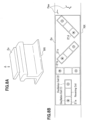
- a detection device 2a comprises 4 sensor sections 21a to 21d and disposed at a position over and opposite the upper face of the railway rail RR. This detection device 2a is mounted on the bottom of and outside the rail flaw checking car.
- the sensor section 21a is disposed in parallel with the longitudinal direction of the railway rail RR.
- the sensor section 21b is disposed in a direction that is orthogonal to the longitudinal direction of the railway rail RR.
- the sensor section 21c is disposed in a diagonal direction that makes an angle of 45 degrees to the longitudinal direction of the railway rail RR.
- the sensor section 21d is disposed in a diagonal direction that is orthogonal to the sensor section 21c.
- the detection device 2a makes use of the sensor sections 21a to 21d whose width is smaller than the width of the railway rail RR, the detection device 2a is capable of detecting with high accuracy a defect of the railway rail that is located at any position in the width direction of the rail way rail RR or is in any shape since it has the plural sensor sections 21a to 21d oriented in different directions that are different from one another as shown in Fig.8B . It is noted that the number of the sensor sections and how these sensors are arranged are not limited to the sensor sections 21a to 21d as shown in Fig.8B .
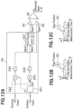
- a detection device 2b comprises an oscillation coil (1) and an oscillation coil (2), whose longitudinal length is so large as to cover the width of the railway rail RR, and N independent receiving coils arranged in parallel with one another and in the width direction of the railway rail RR.
- This detection device 2b is mounted, for example, on the bottom of and outside the rail flaw checking car.
- the rail check system with this detection device 2b is different from the rail check system 1a shown in Fig.7 , since it has only one set of the oscillation coils (1), (2) and only one amplification section 31 for them. Except for the numbers of the amplification sections 31 and the sets of the oscillation coils (1), (2), the rail check system with this detection device 2b is the same as the rail check system 1a and is not indicated with a figure.
- a signal that is influenced by the flaw is outputted by one of the receiving coils that is disposed over a position in the width direction on the railway rail RR where the flaw exists. Accordingly, wherever a flaw exists in the width direction on the railway rail, it is possible to detect the flaw with high accuracy and determine the position in the width direction, where the flaw exists. Furthermore, since the detection device 2b needs only one set of the oscillation coils (1), (2) and only one amplification section 31, the whole circuit is made smaller, which contributes to low power consumption, low cost and a compact system.
- the flaw location method is intended to determine a position in the rail longitudinal direction (hereinafter may be referred to as "longitudinal direction position") where a flaw is when the flaw is detected on or in the railway rail RR.
- the output signal from the receiving coil is indicated in a graph having the sensor output on a vertical axis and a measurement time (time of measurement) T on a horizontal axis.
- senor outputs P1 to P5 indicate signals caused by flaws.
- flaws cannot be located in the rail longitudinal direction with this graph.
- a relation between a speed (V) of a train (rail flaw checking car) and a measurement time T is obtained using L and T L . Integrating the speed (V), a relation between a travel distance (A) and the measurement time (T) is obtained, as shown in Fig.10B (b4).
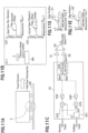
- the signal X corresponds to a cosine component of the input signal, that is, the output of the receiving coil.
- This cosine component is synchronized with the magnetic field that is excited by the oscillation coils (1), (2) (phase difference equal to 0).
- a phase comparison unit 342 receives the output of the receiving coil and 0 degree phase information from a component division unit 341 that receives the oscillation output and outputs the cosine component of the output of the receiving coil.
- the output of the phase comparison unit 342 passes through a low-pass filter circuit 344 and is inputted as the signal X to a gain adjustment circuit 51 and an arithmetic operation circuit 346.
- a signal Y corresponds to a sin component of the input signal (output signal of the receiving coil), whose phase is shifted from the magnetic field by 90 degrees.
- a phase comparison unit 343 receives the output of the receiving coil and 90 degrees phase information from the component division unit 341 that receives the oscillation output and outputs the sine component of the receiving coil.
- the output of the phase comparison unit 343 passes through the low-pass filter circuit 345 and is inputted as the signal Y to the arithmetic operation circuit 346.
- the signal R (equal to a square root of (X 2 + Y 2 )) corresponds to an amplitude value of the output of the receiving coil and is generated by the arithmetic operation circuit 346 to which the signals X, Y are inputted.
- the signal R generated by the arithmetic operation circuit 346 is inputted to the gain adjustment unit 52.
- a differential signal generating unit 53 generates a differential signal (R - X) after the gain adjustments are performed on the signals R, X . Then a deviation of the differential signal (R - X) for the flaw from 0 is so much larger than that for the other points that the flaw can be identified.
- Fig.1 1 A duplicate explanation that has been made for Fig.1 1 is omitted below.
- the signal ⁇ indicates a phase difference of the inputted signal from the reference signal (outputted from the oscillation section 33 in Fig.5 and Fig.7 ) and is generated by an arithmetic operation circuit 347 to which the signal X and the signal Y are inputted.
- the signal ⁇ generated by the arithmetic operation circuit 347 is inputted to a gain adjustment section 54, while the signal X is inputted to a gain adjustment section 55.
- a differential signal generating unit 56 generates a differential signal (X - ⁇ ) after the gain adjustments are performed on the signals X, ⁇ . Then a deviation of the differential signal (X - ⁇ ) for the flaw from 0 is so much larger than that for the other points that the flaw can be identified.
- the distance between coils indicates a distance from the center of the oscillation coil (1) (or the oscillation coil (2)) to the center of the receiving coil.
- the sensor section when the sensor section is intended to detect a flaw on a surface of the rail, the sensor section has a first distance corresponding to the distance between coils.
- This first distance should depend on a distance between the sensor section and the railway rail PR, a material of which the railway rail PR is made, a cross section shape of the railway rail PR and the like, and can be determined through experiments.
- the sensor section when the sensor section is intended to detect a flaw in the rail, the sensor section has a second distance corresponding to the distance between coils that is larger than the first distance. This second distance can also be determined through experiments.
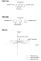
- Fig.14 indications to distinguish the size of a flaw is explained.
- Fig.14 are drawn several tracks based on the signal X and the signal Y on the X-Y coordinate plane. If there is no flaw detected, the track is a point. If there is a flaw detected, the track is, for example, in the shape of a letter "8". Since the larger the track in the shape of a letter "8", the larger the flaw size, it is possible for those who look at the track to recognize the flaw size.
- the flaw detection device 2 utilizes the sensor section 21 inclusive of the oscillation coil (1), the receiving coil and the oscillation coil (2) which are arranged in this order on a plane opposite the rail to be checked, generates from the oscillation coils (1), (2) alternating current magnetic fields whose directions are opposite to each other and is capable of detecting a defect on and in the rail used for the vehicle with a high SN ratio by outputting the magnetic field waveform as check data from the receiving coil
- a portion at which a defect is in a railway rail RR can be determined by the evaluation device 4 performing the check process based on the check data received from the detection device 2.
Landscapes
- Chemical & Material Sciences (AREA)
- Chemical Kinetics & Catalysis (AREA)
- Electrochemistry (AREA)
- Physics & Mathematics (AREA)
- Health & Medical Sciences (AREA)
- Life Sciences & Earth Sciences (AREA)
- Analytical Chemistry (AREA)
- Biochemistry (AREA)
- General Health & Medical Sciences (AREA)
- General Physics & Mathematics (AREA)
- Immunology (AREA)
- Pathology (AREA)
- Engineering & Computer Science (AREA)
- Mechanical Engineering (AREA)
- Investigating Or Analyzing Materials By The Use Of Magnetic Means (AREA)
Applications Claiming Priority (2)
| Application Number | Priority Date | Filing Date | Title |
|---|---|---|---|
| JP2015137823A JP6506122B2 (ja) | 2015-07-09 | 2015-07-09 | レール検査装置、および、レール検査システム |
| PCT/JP2016/057801 WO2017006589A1 (ja) | 2015-07-09 | 2016-03-11 | レール検査装置、および、レール検査システム |
Publications (3)
| Publication Number | Publication Date |
|---|---|
| EP3321671A1 EP3321671A1 (en) | 2018-05-16 |
| EP3321671A4 EP3321671A4 (en) | 2019-01-09 |
| EP3321671B1 true EP3321671B1 (en) | 2023-11-29 |
Family
ID=57684969
Family Applications (1)
| Application Number | Title | Priority Date | Filing Date |
|---|---|---|---|
| EP16821060.7A Active EP3321671B1 (en) | 2015-07-09 | 2016-03-11 | Rail inspection device and rail inspection system |
Country Status (4)
| Country | Link |
|---|---|
| US (1) | US10591442B2 (enExample) |
| EP (1) | EP3321671B1 (enExample) |
| JP (1) | JP6506122B2 (enExample) |
| WO (1) | WO2017006589A1 (enExample) |
Families Citing this family (17)
| Publication number | Priority date | Publication date | Assignee | Title |
|---|---|---|---|---|
| US9849895B2 (en) | 2015-01-19 | 2017-12-26 | Tetra Tech, Inc. | Sensor synchronization apparatus and method |
| US10349491B2 (en) | 2015-01-19 | 2019-07-09 | Tetra Tech, Inc. | Light emission power control apparatus and method |
| CA2892952C (en) | 2015-01-19 | 2019-10-15 | Tetra Tech, Inc. | Protective shroud |
| CA2892885C (en) | 2015-02-20 | 2020-07-28 | Tetra Tech, Inc. | 3d track assessment system and method |
| JP6625489B2 (ja) * | 2016-06-28 | 2019-12-25 | 株式会社日立ハイテクファインシステムズ | レール検査システム |
| JP6768486B2 (ja) * | 2016-12-21 | 2020-10-14 | 株式会社日立ハイテクファインシステムズ | レール検査システム |
| WO2019196998A1 (en) * | 2018-04-09 | 2019-10-17 | Københavns Universitet | An eddy-current detector and a method for calibrating such an eddy-current detector |
| US11377130B2 (en) | 2018-06-01 | 2022-07-05 | Tetra Tech, Inc. | Autonomous track assessment system |
| US10625760B2 (en) | 2018-06-01 | 2020-04-21 | Tetra Tech, Inc. | Apparatus and method for calculating wooden crosstie plate cut measurements and rail seat abrasion measurements based on rail head height |
| US10807623B2 (en) | 2018-06-01 | 2020-10-20 | Tetra Tech, Inc. | Apparatus and method for gathering data from sensors oriented at an oblique angle relative to a railway track |
| AU2020273465C8 (en) | 2019-05-16 | 2025-11-13 | Tetra Tech, Inc. | System and method for generating and interpreting point clouds of a rail corridor along a survey path |
| CN113970709A (zh) * | 2021-10-27 | 2022-01-25 | 徐州中矿传动轨道科技有限公司 | 一种地铁钢轨对地局部绝缘损坏点定位方法及系统 |
| JP2023181824A (ja) * | 2022-06-13 | 2023-12-25 | 株式会社日立製作所 | レール状態監視装置およびレール状態監視方法 |
| DE102023210255A1 (de) | 2023-10-19 | 2025-04-24 | Robert Bosch Gesellschaft mit beschränkter Haftung | Verfahren zum Erkennen von Schäden/Defekten einer mittels eines Schienenfahrzeugs befahrenen Schiene eines Gleises basierend auf Magnetfelddaten |
| DE102023210254A1 (de) | 2023-10-19 | 2025-04-24 | Robert Bosch Gesellschaft mit beschränkter Haftung | Verfahren zum Erkennen von fehlerhaften Schienenelementen eines Gleises basierend auf Magnetfelddaten |
| DE102023210253A1 (de) | 2023-10-19 | 2025-04-24 | Robert Bosch Gesellschaft mit beschränkter Haftung | Verfahren zum Erkennen einer oder mehrerer fehlender Schwellenklammern einer mittels eines Schienenfahrzeugs befahrenen Schiene eines Gleises basierend auf Magnetfelddaten |
| BE1032468B1 (de) * | 2024-03-14 | 2025-10-13 | Rosenxt Holding Ag | Inspektionsvorrichtung für Betonspannelemente |
Family Cites Families (30)
| Publication number | Priority date | Publication date | Assignee | Title |
|---|---|---|---|---|
| US2203256A (en) * | 1938-12-15 | 1940-06-04 | Sperry Prod Inc | Rail flaw detector mechanism |
| US2622131A (en) * | 1945-11-13 | 1952-12-16 | Teledetector Inc | Portable rail flaw detector |
| US2602840A (en) * | 1947-05-20 | 1952-07-08 | Teledetector Inc | Electromagnet for rail fissure detectors |
| US2682442A (en) * | 1948-07-23 | 1954-06-29 | Frank H Keaton | Indicating means for rail flaw detecting apparatus |
| US2671197A (en) * | 1950-09-02 | 1954-03-02 | Walter C Barnes | Magnetizing means for rail flaw detector systems |
| US2766424A (en) * | 1951-11-15 | 1956-10-09 | Teleweld Inc | Method and apparatus for detecting fissures in rail |
| US2869073A (en) * | 1953-03-09 | 1959-01-13 | Teleweld Inc | Method and apparatus for distinguishing harmless surface flaws from dangerous fissures in magnetizable bodies |
| US3271662A (en) * | 1962-08-22 | 1966-09-06 | Api Instr Company | Flaw detecting apparatus having multiple pick-up and exciting coils on the same side of the test piece |
| JPS63235854A (ja) | 1987-03-24 | 1988-09-30 | Sumitomo Metal Ind Ltd | 探傷装置 |
| JP3298748B2 (ja) * | 1994-09-30 | 2002-07-08 | 東京瓦斯株式会社 | 導管検査用ピグの走行監視システム |
| US5623244A (en) * | 1996-05-10 | 1997-04-22 | The United States Of America As Represented By The Secretary Of The Navy | Pilot vehicle which is useful for monitoring hazardous conditions on railroad tracks |
| US5786750A (en) * | 1996-05-10 | 1998-07-28 | The United States Of America As Represented By The Secretary Of The Navy | Pilot vehicle which is useful for monitoring hazardous conditions on railroad tracks |
| JP2001108659A (ja) * | 1999-10-07 | 2001-04-20 | Amikku:Kk | 金属表面探傷用渦流プローブ |
| AU2001288433A1 (en) * | 2000-08-25 | 2002-03-04 | Em-Tech Llc | Detection of anomalies on railroad tracks |
| JP4681770B2 (ja) * | 2001-08-07 | 2011-05-11 | マークテック株式会社 | 渦流探傷試験装置 |
| EP1436604B1 (en) * | 2001-10-17 | 2015-09-09 | GE Oil & Gas UK Limited | Method for measuring material properties and lift-off components of an object using a magnetic probe |
| JP3796570B2 (ja) * | 2002-03-15 | 2006-07-12 | ▲高▼木 敏行 | 渦電流探傷法及び探傷プローブ |
| JP2004279055A (ja) * | 2003-03-12 | 2004-10-07 | Sumitomo Metal Ind Ltd | 鋼管内面の浸炭深さ測定方法及び装置 |
| JP2004279372A (ja) * | 2003-03-19 | 2004-10-07 | Yazaki Corp | 破断検出方法 |
| JP4586556B2 (ja) * | 2005-02-10 | 2010-11-24 | Jfeスチール株式会社 | 表層部性状測定方法及びそれを用いた表層欠陥判定方法、並びに金属帯の製造方法 |
| US8049494B2 (en) * | 2007-05-21 | 2011-11-01 | Olympus Ndt | Flexible array probe for the inspection of a contoured surface with varying cross-sectional geometry |
| WO2009083996A2 (en) * | 2007-12-31 | 2009-07-09 | General Electric Company | Method for compensation of responses from eddy current probes |
| JP4863127B2 (ja) | 2008-05-15 | 2012-01-25 | 住友金属工業株式会社 | 磁気探傷方法及び磁気探傷装置 |
| US20130024135A1 (en) * | 2011-07-22 | 2013-01-24 | Blum Dieter W | Method And Apparatus For Ferromagnetic Cable Inspection |
| EP2746761B8 (en) * | 2011-08-18 | 2019-08-21 | Nippon Steel Corporation | Method for magnetic flaw detection and magnetic flaw detector |
| JP2013185951A (ja) * | 2012-03-08 | 2013-09-19 | Jfe Steel Corp | 電磁気探傷用プローブ |
| JP2014044151A (ja) * | 2012-08-28 | 2014-03-13 | N D R Kk | 欠陥検出装置 |
| JP2014066688A (ja) | 2012-09-27 | 2014-04-17 | Hosei Univ | 渦流探傷プローブ、渦流探傷装置 |
| US9669851B2 (en) * | 2012-11-21 | 2017-06-06 | General Electric Company | Route examination system and method |
| JP2014102197A (ja) * | 2012-11-21 | 2014-06-05 | Meielec:Kk | 磁気誘導式レール探傷方法及び磁気誘導式レール探傷装置 |
-
2015
- 2015-07-09 JP JP2015137823A patent/JP6506122B2/ja active Active
-
2016
- 2016-03-11 EP EP16821060.7A patent/EP3321671B1/en active Active
- 2016-03-11 US US15/740,020 patent/US10591442B2/en active Active
- 2016-03-11 WO PCT/JP2016/057801 patent/WO2017006589A1/ja not_active Ceased
Also Published As
| Publication number | Publication date |
|---|---|
| US20180172639A1 (en) | 2018-06-21 |
| EP3321671A1 (en) | 2018-05-16 |
| EP3321671A4 (en) | 2019-01-09 |
| JP6506122B2 (ja) | 2019-04-24 |
| JP2017020862A (ja) | 2017-01-26 |
| US10591442B2 (en) | 2020-03-17 |
| WO2017006589A1 (ja) | 2017-01-12 |
Similar Documents
| Publication | Publication Date | Title |
|---|---|---|
| EP3321671B1 (en) | Rail inspection device and rail inspection system | |
| CN104903717B (zh) | 用于探测导电材料中的异常的微分传感器、检验系统和方法 | |
| US20130193959A1 (en) | Detection of a Metal or Magnetic Object | |
| US10989694B2 (en) | Rail inspection system | |
| CN102870011B (zh) | 金属的或磁性对象的检测 | |
| JPH0854375A (ja) | 電磁誘導型検査装置 | |
| JP7351341B2 (ja) | 非破壊検査の情報処理システム及び非破壊検査方法 | |
| CN108872368A (zh) | 一种改进型无方向性正交涡流检测装置 | |
| JP6843430B2 (ja) | 鉄筋コンクリートの鉄筋径とかぶりの測定装置 | |
| JP2019168253A (ja) | 磁性体検査システム、磁性体検査装置および磁性体検査方法 | |
| JP2017015586A (ja) | ロープ検査装置、および、ロープ検査システム | |
| CN116075719A (zh) | 钢丝绳检查装置和钢丝绳检查系统 | |
| US10739311B2 (en) | Rail inspection system | |
| US11674927B2 (en) | Eddy current flaw detection apparatus | |
| JPH11304405A (ja) | 位置検出装置及びそれを用いた位置検出方法 | |
| JP2016057225A (ja) | 渦電流探傷センサ装置 | |
| EP3159854B1 (en) | Coin detection system | |
| CN107907040A (zh) | 一种基于交流磁桥回路的位移传感方法和装置 | |
| EP3081932B1 (en) | Apparatus and method of inspecting defect of steel plate | |
| JP4835995B2 (ja) | 漏洩磁束探傷法及び漏洩磁束探傷装置 | |
| KR101679520B1 (ko) | 다채널 rfect를 이용한 배관의 결함 폭 측정 시스템 및 이를 이용한 측정방법 | |
| US6188217B1 (en) | Inductive measurement device for determining dimensions of objects | |
| EP4589290A1 (en) | Non-destructive testing method, program, and non-destructive testing system | |
| JP2021162360A (ja) | 検査方法および検査装置 | |
| JP2015194488A (ja) | 位置検出装置 |
Legal Events
| Date | Code | Title | Description |
|---|---|---|---|
| STAA | Information on the status of an ep patent application or granted ep patent |
Free format text: STATUS: THE INTERNATIONAL PUBLICATION HAS BEEN MADE |
|
| PUAI | Public reference made under article 153(3) epc to a published international application that has entered the european phase |
Free format text: ORIGINAL CODE: 0009012 |
|
| STAA | Information on the status of an ep patent application or granted ep patent |
Free format text: STATUS: REQUEST FOR EXAMINATION WAS MADE |
|
| 17P | Request for examination filed |
Effective date: 20180209 |
|
| AK | Designated contracting states |
Kind code of ref document: A1 Designated state(s): AL AT BE BG CH CY CZ DE DK EE ES FI FR GB GR HR HU IE IS IT LI LT LU LV MC MK MT NL NO PL PT RO RS SE SI SK SM TR |
|
| AX | Request for extension of the european patent |
Extension state: BA ME |
|
| DAV | Request for validation of the european patent (deleted) | ||
| DAX | Request for extension of the european patent (deleted) | ||
| A4 | Supplementary search report drawn up and despatched |
Effective date: 20181207 |
|
| RIC1 | Information provided on ipc code assigned before grant |
Ipc: G01N 27/83 20060101AFI20181203BHEP |
|
| RAP1 | Party data changed (applicant data changed or rights of an application transferred) |
Owner name: HITACHI HIGH-TECH CORPORATION |
|
| STAA | Information on the status of an ep patent application or granted ep patent |
Free format text: STATUS: EXAMINATION IS IN PROGRESS |
|
| 17Q | First examination report despatched |
Effective date: 20211213 |
|
| GRAP | Despatch of communication of intention to grant a patent |
Free format text: ORIGINAL CODE: EPIDOSNIGR1 |
|
| STAA | Information on the status of an ep patent application or granted ep patent |
Free format text: STATUS: GRANT OF PATENT IS INTENDED |
|
| RIC1 | Information provided on ipc code assigned before grant |
Ipc: B61K 9/10 20060101ALI20230724BHEP Ipc: G01N 27/83 20060101AFI20230724BHEP |
|
| INTG | Intention to grant announced |
Effective date: 20230821 |
|
| GRAS | Grant fee paid |
Free format text: ORIGINAL CODE: EPIDOSNIGR3 |
|
| GRAA | (expected) grant |
Free format text: ORIGINAL CODE: 0009210 |
|
| STAA | Information on the status of an ep patent application or granted ep patent |
Free format text: STATUS: THE PATENT HAS BEEN GRANTED |
|
| AK | Designated contracting states |
Kind code of ref document: B1 Designated state(s): AL AT BE BG CH CY CZ DE DK EE ES FI FR GB GR HR HU IE IS IT LI LT LU LV MC MK MT NL NO PL PT RO RS SE SI SK SM TR |
|
| REG | Reference to a national code |
Ref country code: GB Ref legal event code: FG4D |
|
| REG | Reference to a national code |
Ref country code: CH Ref legal event code: EP |
|
| REG | Reference to a national code |
Ref country code: DE Ref legal event code: R096 Ref document number: 602016084430 Country of ref document: DE |
|
| REG | Reference to a national code |
Ref country code: IE Ref legal event code: FG4D |
|
| REG | Reference to a national code |
Ref country code: LT Ref legal event code: MG9D |
|
| REG | Reference to a national code |
Ref country code: NL Ref legal event code: MP Effective date: 20231129 |
|
| PG25 | Lapsed in a contracting state [announced via postgrant information from national office to epo] |
Ref country code: GR Free format text: LAPSE BECAUSE OF FAILURE TO SUBMIT A TRANSLATION OF THE DESCRIPTION OR TO PAY THE FEE WITHIN THE PRESCRIBED TIME-LIMIT Effective date: 20240301 |
|
| PG25 | Lapsed in a contracting state [announced via postgrant information from national office to epo] |
Ref country code: IS Free format text: LAPSE BECAUSE OF FAILURE TO SUBMIT A TRANSLATION OF THE DESCRIPTION OR TO PAY THE FEE WITHIN THE PRESCRIBED TIME-LIMIT Effective date: 20240329 |
|
| PG25 | Lapsed in a contracting state [announced via postgrant information from national office to epo] |
Ref country code: LT Free format text: LAPSE BECAUSE OF FAILURE TO SUBMIT A TRANSLATION OF THE DESCRIPTION OR TO PAY THE FEE WITHIN THE PRESCRIBED TIME-LIMIT Effective date: 20231129 |
|
| PG25 | Lapsed in a contracting state [announced via postgrant information from national office to epo] |
Ref country code: ES Free format text: LAPSE BECAUSE OF FAILURE TO SUBMIT A TRANSLATION OF THE DESCRIPTION OR TO PAY THE FEE WITHIN THE PRESCRIBED TIME-LIMIT Effective date: 20231129 |
|
| PG25 | Lapsed in a contracting state [announced via postgrant information from national office to epo] |
Ref country code: LT Free format text: LAPSE BECAUSE OF FAILURE TO SUBMIT A TRANSLATION OF THE DESCRIPTION OR TO PAY THE FEE WITHIN THE PRESCRIBED TIME-LIMIT Effective date: 20231129 Ref country code: IS Free format text: LAPSE BECAUSE OF FAILURE TO SUBMIT A TRANSLATION OF THE DESCRIPTION OR TO PAY THE FEE WITHIN THE PRESCRIBED TIME-LIMIT Effective date: 20240329 Ref country code: GR Free format text: LAPSE BECAUSE OF FAILURE TO SUBMIT A TRANSLATION OF THE DESCRIPTION OR TO PAY THE FEE WITHIN THE PRESCRIBED TIME-LIMIT Effective date: 20240301 Ref country code: ES Free format text: LAPSE BECAUSE OF FAILURE TO SUBMIT A TRANSLATION OF THE DESCRIPTION OR TO PAY THE FEE WITHIN THE PRESCRIBED TIME-LIMIT Effective date: 20231129 Ref country code: BG Free format text: LAPSE BECAUSE OF FAILURE TO SUBMIT A TRANSLATION OF THE DESCRIPTION OR TO PAY THE FEE WITHIN THE PRESCRIBED TIME-LIMIT Effective date: 20240229 |
|
| REG | Reference to a national code |
Ref country code: AT Ref legal event code: MK05 Ref document number: 1636628 Country of ref document: AT Kind code of ref document: T Effective date: 20231129 |
|
| PG25 | Lapsed in a contracting state [announced via postgrant information from national office to epo] |
Ref country code: NL Free format text: LAPSE BECAUSE OF FAILURE TO SUBMIT A TRANSLATION OF THE DESCRIPTION OR TO PAY THE FEE WITHIN THE PRESCRIBED TIME-LIMIT Effective date: 20231129 |
|
| PG25 | Lapsed in a contracting state [announced via postgrant information from national office to epo] |
Ref country code: SE Free format text: LAPSE BECAUSE OF FAILURE TO SUBMIT A TRANSLATION OF THE DESCRIPTION OR TO PAY THE FEE WITHIN THE PRESCRIBED TIME-LIMIT Effective date: 20231129 Ref country code: RS Free format text: LAPSE BECAUSE OF FAILURE TO SUBMIT A TRANSLATION OF THE DESCRIPTION OR TO PAY THE FEE WITHIN THE PRESCRIBED TIME-LIMIT Effective date: 20231129 Ref country code: PL Free format text: LAPSE BECAUSE OF FAILURE TO SUBMIT A TRANSLATION OF THE DESCRIPTION OR TO PAY THE FEE WITHIN THE PRESCRIBED TIME-LIMIT Effective date: 20231129 Ref country code: NO Free format text: LAPSE BECAUSE OF FAILURE TO SUBMIT A TRANSLATION OF THE DESCRIPTION OR TO PAY THE FEE WITHIN THE PRESCRIBED TIME-LIMIT Effective date: 20240229 Ref country code: NL Free format text: LAPSE BECAUSE OF FAILURE TO SUBMIT A TRANSLATION OF THE DESCRIPTION OR TO PAY THE FEE WITHIN THE PRESCRIBED TIME-LIMIT Effective date: 20231129 Ref country code: LV Free format text: LAPSE BECAUSE OF FAILURE TO SUBMIT A TRANSLATION OF THE DESCRIPTION OR TO PAY THE FEE WITHIN THE PRESCRIBED TIME-LIMIT Effective date: 20231129 Ref country code: HR Free format text: LAPSE BECAUSE OF FAILURE TO SUBMIT A TRANSLATION OF THE DESCRIPTION OR TO PAY THE FEE WITHIN THE PRESCRIBED TIME-LIMIT Effective date: 20231129 |
|
| PG25 | Lapsed in a contracting state [announced via postgrant information from national office to epo] |
Ref country code: DK Free format text: LAPSE BECAUSE OF FAILURE TO SUBMIT A TRANSLATION OF THE DESCRIPTION OR TO PAY THE FEE WITHIN THE PRESCRIBED TIME-LIMIT Effective date: 20231129 |
|
| PG25 | Lapsed in a contracting state [announced via postgrant information from national office to epo] |
Ref country code: AT Free format text: LAPSE BECAUSE OF FAILURE TO SUBMIT A TRANSLATION OF THE DESCRIPTION OR TO PAY THE FEE WITHIN THE PRESCRIBED TIME-LIMIT Effective date: 20231129 Ref country code: CZ Free format text: LAPSE BECAUSE OF FAILURE TO SUBMIT A TRANSLATION OF THE DESCRIPTION OR TO PAY THE FEE WITHIN THE PRESCRIBED TIME-LIMIT Effective date: 20231129 |
|
| PG25 | Lapsed in a contracting state [announced via postgrant information from national office to epo] |
Ref country code: SK Free format text: LAPSE BECAUSE OF FAILURE TO SUBMIT A TRANSLATION OF THE DESCRIPTION OR TO PAY THE FEE WITHIN THE PRESCRIBED TIME-LIMIT Effective date: 20231129 |
|
| PG25 | Lapsed in a contracting state [announced via postgrant information from national office to epo] |
Ref country code: SM Free format text: LAPSE BECAUSE OF FAILURE TO SUBMIT A TRANSLATION OF THE DESCRIPTION OR TO PAY THE FEE WITHIN THE PRESCRIBED TIME-LIMIT Effective date: 20231129 Ref country code: SK Free format text: LAPSE BECAUSE OF FAILURE TO SUBMIT A TRANSLATION OF THE DESCRIPTION OR TO PAY THE FEE WITHIN THE PRESCRIBED TIME-LIMIT Effective date: 20231129 Ref country code: RO Free format text: LAPSE BECAUSE OF FAILURE TO SUBMIT A TRANSLATION OF THE DESCRIPTION OR TO PAY THE FEE WITHIN THE PRESCRIBED TIME-LIMIT Effective date: 20231129 Ref country code: EE Free format text: LAPSE BECAUSE OF FAILURE TO SUBMIT A TRANSLATION OF THE DESCRIPTION OR TO PAY THE FEE WITHIN THE PRESCRIBED TIME-LIMIT Effective date: 20231129 Ref country code: DK Free format text: LAPSE BECAUSE OF FAILURE TO SUBMIT A TRANSLATION OF THE DESCRIPTION OR TO PAY THE FEE WITHIN THE PRESCRIBED TIME-LIMIT Effective date: 20231129 Ref country code: CZ Free format text: LAPSE BECAUSE OF FAILURE TO SUBMIT A TRANSLATION OF THE DESCRIPTION OR TO PAY THE FEE WITHIN THE PRESCRIBED TIME-LIMIT Effective date: 20231129 Ref country code: AT Free format text: LAPSE BECAUSE OF FAILURE TO SUBMIT A TRANSLATION OF THE DESCRIPTION OR TO PAY THE FEE WITHIN THE PRESCRIBED TIME-LIMIT Effective date: 20231129 |
|
| PG25 | Lapsed in a contracting state [announced via postgrant information from national office to epo] |
Ref country code: PT Free format text: LAPSE BECAUSE OF FAILURE TO SUBMIT A TRANSLATION OF THE DESCRIPTION OR TO PAY THE FEE WITHIN THE PRESCRIBED TIME-LIMIT Effective date: 20240401 |
|
| PG25 | Lapsed in a contracting state [announced via postgrant information from national office to epo] |
Ref country code: PT Free format text: LAPSE BECAUSE OF FAILURE TO SUBMIT A TRANSLATION OF THE DESCRIPTION OR TO PAY THE FEE WITHIN THE PRESCRIBED TIME-LIMIT Effective date: 20240401 |
|
| REG | Reference to a national code |
Ref country code: DE Ref legal event code: R097 Ref document number: 602016084430 Country of ref document: DE |
|
| PLBE | No opposition filed within time limit |
Free format text: ORIGINAL CODE: 0009261 |
|
| STAA | Information on the status of an ep patent application or granted ep patent |
Free format text: STATUS: NO OPPOSITION FILED WITHIN TIME LIMIT |
|
| PG25 | Lapsed in a contracting state [announced via postgrant information from national office to epo] |
Ref country code: SI Free format text: LAPSE BECAUSE OF FAILURE TO SUBMIT A TRANSLATION OF THE DESCRIPTION OR TO PAY THE FEE WITHIN THE PRESCRIBED TIME-LIMIT Effective date: 20231129 |
|
| PG25 | Lapsed in a contracting state [announced via postgrant information from national office to epo] |
Ref country code: SI Free format text: LAPSE BECAUSE OF FAILURE TO SUBMIT A TRANSLATION OF THE DESCRIPTION OR TO PAY THE FEE WITHIN THE PRESCRIBED TIME-LIMIT Effective date: 20231129 |
|
| REG | Reference to a national code |
Ref country code: CH Ref legal event code: PL |
|
| 26N | No opposition filed |
Effective date: 20240830 |
|
| PG25 | Lapsed in a contracting state [announced via postgrant information from national office to epo] |
Ref country code: LU Free format text: LAPSE BECAUSE OF NON-PAYMENT OF DUE FEES Effective date: 20240311 |
|
| PG25 | Lapsed in a contracting state [announced via postgrant information from national office to epo] |
Ref country code: MC Free format text: LAPSE BECAUSE OF FAILURE TO SUBMIT A TRANSLATION OF THE DESCRIPTION OR TO PAY THE FEE WITHIN THE PRESCRIBED TIME-LIMIT Effective date: 20231129 |
|
| PG25 | Lapsed in a contracting state [announced via postgrant information from national office to epo] |
Ref country code: MC Free format text: LAPSE BECAUSE OF FAILURE TO SUBMIT A TRANSLATION OF THE DESCRIPTION OR TO PAY THE FEE WITHIN THE PRESCRIBED TIME-LIMIT Effective date: 20231129 Ref country code: LU Free format text: LAPSE BECAUSE OF NON-PAYMENT OF DUE FEES Effective date: 20240311 |
|
| REG | Reference to a national code |
Ref country code: BE Ref legal event code: MM Effective date: 20240331 |
|
| PG25 | Lapsed in a contracting state [announced via postgrant information from national office to epo] |
Ref country code: BE Free format text: LAPSE BECAUSE OF NON-PAYMENT OF DUE FEES Effective date: 20240331 |
|
| PG25 | Lapsed in a contracting state [announced via postgrant information from national office to epo] |
Ref country code: FR Free format text: LAPSE BECAUSE OF NON-PAYMENT OF DUE FEES Effective date: 20240331 |
|
| PG25 | Lapsed in a contracting state [announced via postgrant information from national office to epo] |
Ref country code: IE Free format text: LAPSE BECAUSE OF NON-PAYMENT OF DUE FEES Effective date: 20240311 |
|
| PG25 | Lapsed in a contracting state [announced via postgrant information from national office to epo] |
Ref country code: IE Free format text: LAPSE BECAUSE OF NON-PAYMENT OF DUE FEES Effective date: 20240311 Ref country code: FR Free format text: LAPSE BECAUSE OF NON-PAYMENT OF DUE FEES Effective date: 20240331 Ref country code: BE Free format text: LAPSE BECAUSE OF NON-PAYMENT OF DUE FEES Effective date: 20240331 Ref country code: CH Free format text: LAPSE BECAUSE OF NON-PAYMENT OF DUE FEES Effective date: 20240331 |
|
| PGFP | Annual fee paid to national office [announced via postgrant information from national office to epo] |
Ref country code: DE Payment date: 20250128 Year of fee payment: 10 |
|
| PGFP | Annual fee paid to national office [announced via postgrant information from national office to epo] |
Ref country code: IT Payment date: 20250211 Year of fee payment: 10 Ref country code: GB Payment date: 20250130 Year of fee payment: 10 |
|
| PG25 | Lapsed in a contracting state [announced via postgrant information from national office to epo] |
Ref country code: CY Free format text: LAPSE BECAUSE OF FAILURE TO SUBMIT A TRANSLATION OF THE DESCRIPTION OR TO PAY THE FEE WITHIN THE PRESCRIBED TIME-LIMIT; INVALID AB INITIO Effective date: 20160311 |
|
| PG25 | Lapsed in a contracting state [announced via postgrant information from national office to epo] |
Ref country code: HU Free format text: LAPSE BECAUSE OF FAILURE TO SUBMIT A TRANSLATION OF THE DESCRIPTION OR TO PAY THE FEE WITHIN THE PRESCRIBED TIME-LIMIT; INVALID AB INITIO Effective date: 20160311 |
|
| PG25 | Lapsed in a contracting state [announced via postgrant information from national office to epo] |
Ref country code: FI Free format text: LAPSE BECAUSE OF FAILURE TO SUBMIT A TRANSLATION OF THE DESCRIPTION OR TO PAY THE FEE WITHIN THE PRESCRIBED TIME-LIMIT Effective date: 20231129 |