WO2017002669A1 - 運転支援装置、及び運転支援方法 - Google Patents
運転支援装置、及び運転支援方法 Download PDFInfo
- Publication number
- WO2017002669A1 WO2017002669A1 PCT/JP2016/068391 JP2016068391W WO2017002669A1 WO 2017002669 A1 WO2017002669 A1 WO 2017002669A1 JP 2016068391 W JP2016068391 W JP 2016068391W WO 2017002669 A1 WO2017002669 A1 WO 2017002669A1
- Authority
- WO
- WIPO (PCT)
- Prior art keywords
- vehicle
- distance
- resistance
- driving support
- determination unit
- Prior art date
- Legal status (The legal status is an assumption and is not a legal conclusion. Google has not performed a legal analysis and makes no representation as to the accuracy of the status listed.)
- Ceased
Links
Images



Classifications
-
- B—PERFORMING OPERATIONS; TRANSPORTING
- B60—VEHICLES IN GENERAL
- B60W—CONJOINT CONTROL OF VEHICLE SUB-UNITS OF DIFFERENT TYPE OR DIFFERENT FUNCTION; CONTROL SYSTEMS SPECIALLY ADAPTED FOR HYBRID VEHICLES; ROAD VEHICLE DRIVE CONTROL SYSTEMS FOR PURPOSES NOT RELATED TO THE CONTROL OF A PARTICULAR SUB-UNIT
- B60W30/00—Purposes of road vehicle drive control systems not related to the control of a particular sub-unit, e.g. of systems using conjoint control of vehicle sub-units
- B60W30/08—Active safety systems predicting or avoiding probable or impending collision or attempting to minimise its consequences
-
- B—PERFORMING OPERATIONS; TRANSPORTING
- B60—VEHICLES IN GENERAL
- B60W—CONJOINT CONTROL OF VEHICLE SUB-UNITS OF DIFFERENT TYPE OR DIFFERENT FUNCTION; CONTROL SYSTEMS SPECIALLY ADAPTED FOR HYBRID VEHICLES; ROAD VEHICLE DRIVE CONTROL SYSTEMS FOR PURPOSES NOT RELATED TO THE CONTROL OF A PARTICULAR SUB-UNIT
- B60W30/00—Purposes of road vehicle drive control systems not related to the control of a particular sub-unit, e.g. of systems using conjoint control of vehicle sub-units
- B60W30/08—Active safety systems predicting or avoiding probable or impending collision or attempting to minimise its consequences
- B60W30/09—Taking automatic action to avoid collision, e.g. braking and steering
-
- B—PERFORMING OPERATIONS; TRANSPORTING
- B60—VEHICLES IN GENERAL
- B60W—CONJOINT CONTROL OF VEHICLE SUB-UNITS OF DIFFERENT TYPE OR DIFFERENT FUNCTION; CONTROL SYSTEMS SPECIALLY ADAPTED FOR HYBRID VEHICLES; ROAD VEHICLE DRIVE CONTROL SYSTEMS FOR PURPOSES NOT RELATED TO THE CONTROL OF A PARTICULAR SUB-UNIT
- B60W30/00—Purposes of road vehicle drive control systems not related to the control of a particular sub-unit, e.g. of systems using conjoint control of vehicle sub-units
- B60W30/18—Propelling the vehicle
- B60W30/18009—Propelling the vehicle related to particular drive situations
- B60W30/18036—Reversing
-
- B—PERFORMING OPERATIONS; TRANSPORTING
- B60—VEHICLES IN GENERAL
- B60W—CONJOINT CONTROL OF VEHICLE SUB-UNITS OF DIFFERENT TYPE OR DIFFERENT FUNCTION; CONTROL SYSTEMS SPECIALLY ADAPTED FOR HYBRID VEHICLES; ROAD VEHICLE DRIVE CONTROL SYSTEMS FOR PURPOSES NOT RELATED TO THE CONTROL OF A PARTICULAR SUB-UNIT
- B60W30/00—Purposes of road vehicle drive control systems not related to the control of a particular sub-unit, e.g. of systems using conjoint control of vehicle sub-units
- B60W30/18—Propelling the vehicle
- B60W30/18009—Propelling the vehicle related to particular drive situations
- B60W30/18063—Creeping
-
- B—PERFORMING OPERATIONS; TRANSPORTING
- B60—VEHICLES IN GENERAL
- B60W—CONJOINT CONTROL OF VEHICLE SUB-UNITS OF DIFFERENT TYPE OR DIFFERENT FUNCTION; CONTROL SYSTEMS SPECIALLY ADAPTED FOR HYBRID VEHICLES; ROAD VEHICLE DRIVE CONTROL SYSTEMS FOR PURPOSES NOT RELATED TO THE CONTROL OF A PARTICULAR SUB-UNIT
- B60W50/00—Details of control systems for road vehicle drive control not related to the control of a particular sub-unit, e.g. process diagnostic or vehicle driver interfaces
- B60W50/08—Interaction between the driver and the control system
- B60W50/10—Interpretation of driver requests or demands
-
- G—PHYSICS
- G08—SIGNALLING
- G08G—TRAFFIC CONTROL SYSTEMS
- G08G1/00—Traffic control systems for road vehicles
- G08G1/16—Anti-collision systems
- G08G1/168—Driving aids for parking, e.g. acoustic or visual feedback on parking space
-
- B—PERFORMING OPERATIONS; TRANSPORTING
- B60—VEHICLES IN GENERAL
- B60W—CONJOINT CONTROL OF VEHICLE SUB-UNITS OF DIFFERENT TYPE OR DIFFERENT FUNCTION; CONTROL SYSTEMS SPECIALLY ADAPTED FOR HYBRID VEHICLES; ROAD VEHICLE DRIVE CONTROL SYSTEMS FOR PURPOSES NOT RELATED TO THE CONTROL OF A PARTICULAR SUB-UNIT
- B60W2520/00—Input parameters relating to overall vehicle dynamics
- B60W2520/10—Longitudinal speed
-
- B—PERFORMING OPERATIONS; TRANSPORTING
- B60—VEHICLES IN GENERAL
- B60W—CONJOINT CONTROL OF VEHICLE SUB-UNITS OF DIFFERENT TYPE OR DIFFERENT FUNCTION; CONTROL SYSTEMS SPECIALLY ADAPTED FOR HYBRID VEHICLES; ROAD VEHICLE DRIVE CONTROL SYSTEMS FOR PURPOSES NOT RELATED TO THE CONTROL OF A PARTICULAR SUB-UNIT
- B60W2530/00—Input parameters relating to vehicle conditions or values, not covered by groups B60W2510/00 or B60W2520/00
- B60W2530/16—Driving resistance
-
- B—PERFORMING OPERATIONS; TRANSPORTING
- B60—VEHICLES IN GENERAL
- B60W—CONJOINT CONTROL OF VEHICLE SUB-UNITS OF DIFFERENT TYPE OR DIFFERENT FUNCTION; CONTROL SYSTEMS SPECIALLY ADAPTED FOR HYBRID VEHICLES; ROAD VEHICLE DRIVE CONTROL SYSTEMS FOR PURPOSES NOT RELATED TO THE CONTROL OF A PARTICULAR SUB-UNIT
- B60W2540/00—Input parameters relating to occupants
- B60W2540/10—Accelerator pedal position
-
- B—PERFORMING OPERATIONS; TRANSPORTING
- B60—VEHICLES IN GENERAL
- B60W—CONJOINT CONTROL OF VEHICLE SUB-UNITS OF DIFFERENT TYPE OR DIFFERENT FUNCTION; CONTROL SYSTEMS SPECIALLY ADAPTED FOR HYBRID VEHICLES; ROAD VEHICLE DRIVE CONTROL SYSTEMS FOR PURPOSES NOT RELATED TO THE CONTROL OF A PARTICULAR SUB-UNIT
- B60W2552/00—Input parameters relating to infrastructure
- B60W2552/15—Road slope, i.e. the inclination of a road segment in the longitudinal direction
-
- B—PERFORMING OPERATIONS; TRANSPORTING
- B60—VEHICLES IN GENERAL
- B60W—CONJOINT CONTROL OF VEHICLE SUB-UNITS OF DIFFERENT TYPE OR DIFFERENT FUNCTION; CONTROL SYSTEMS SPECIALLY ADAPTED FOR HYBRID VEHICLES; ROAD VEHICLE DRIVE CONTROL SYSTEMS FOR PURPOSES NOT RELATED TO THE CONTROL OF A PARTICULAR SUB-UNIT
- B60W2552/00—Input parameters relating to infrastructure
- B60W2552/35—Road bumpiness, e.g. potholes
-
- B—PERFORMING OPERATIONS; TRANSPORTING
- B60—VEHICLES IN GENERAL
- B60W—CONJOINT CONTROL OF VEHICLE SUB-UNITS OF DIFFERENT TYPE OR DIFFERENT FUNCTION; CONTROL SYSTEMS SPECIALLY ADAPTED FOR HYBRID VEHICLES; ROAD VEHICLE DRIVE CONTROL SYSTEMS FOR PURPOSES NOT RELATED TO THE CONTROL OF A PARTICULAR SUB-UNIT
- B60W2554/00—Input parameters relating to objects
-
- B—PERFORMING OPERATIONS; TRANSPORTING
- B60—VEHICLES IN GENERAL
- B60W—CONJOINT CONTROL OF VEHICLE SUB-UNITS OF DIFFERENT TYPE OR DIFFERENT FUNCTION; CONTROL SYSTEMS SPECIALLY ADAPTED FOR HYBRID VEHICLES; ROAD VEHICLE DRIVE CONTROL SYSTEMS FOR PURPOSES NOT RELATED TO THE CONTROL OF A PARTICULAR SUB-UNIT
- B60W2554/00—Input parameters relating to objects
- B60W2554/20—Static objects
-
- B—PERFORMING OPERATIONS; TRANSPORTING
- B60—VEHICLES IN GENERAL
- B60W—CONJOINT CONTROL OF VEHICLE SUB-UNITS OF DIFFERENT TYPE OR DIFFERENT FUNCTION; CONTROL SYSTEMS SPECIALLY ADAPTED FOR HYBRID VEHICLES; ROAD VEHICLE DRIVE CONTROL SYSTEMS FOR PURPOSES NOT RELATED TO THE CONTROL OF A PARTICULAR SUB-UNIT
- B60W2554/00—Input parameters relating to objects
- B60W2554/60—Traversable objects, e.g. speed bumps or curbs
-
- B—PERFORMING OPERATIONS; TRANSPORTING
- B60—VEHICLES IN GENERAL
- B60W—CONJOINT CONTROL OF VEHICLE SUB-UNITS OF DIFFERENT TYPE OR DIFFERENT FUNCTION; CONTROL SYSTEMS SPECIALLY ADAPTED FOR HYBRID VEHICLES; ROAD VEHICLE DRIVE CONTROL SYSTEMS FOR PURPOSES NOT RELATED TO THE CONTROL OF A PARTICULAR SUB-UNIT
- B60W2554/00—Input parameters relating to objects
- B60W2554/80—Spatial relation or speed relative to objects
- B60W2554/802—Longitudinal distance
Definitions
- the present disclosure relates to a driving support device that detects an object that exists in the traveling direction of the vehicle and controls the vehicle, and a driving support method that is executed by the driving support device.
- a driving assistance device in which a distance measuring sensor such as an ultrasonic sensor is mounted on a vehicle, and an object existing around the vehicle such as a preceding vehicle, a pedestrian, or a structure on the road is detected using the distance measuring sensor.
- This driving support device performs various controls for improving the traveling safety of the vehicle, for example, operation of a braking device, notification to the driver, and the like based on the object detection result of the distance measuring sensor.
- the main purpose of the present disclosure is to provide a driving support device and a driving support method that can appropriately set the distance for operating the collision avoidance device according to the operation of the driver.
- a first aspect of the present disclosure is a driving support device that operates a collision avoidance device mounted on the vehicle according to a distance from an object positioned in front of the vehicle in the traveling direction, and the traveling direction of the vehicle
- a resistance determination unit that determines whether or not there is a running resistance that suppresses rolling of the wheel forward
- an operation determination unit that determines whether or not an accelerator operation is performed by a driver of the vehicle
- the collision avoidance A distance setting unit that sets a working distance that is a distance for operating the device, wherein the distance setting unit determines that the resistance determination unit exists and the operation determination unit includes the operation determination unit.
- the working distance is set to a smaller value than when the running resistance is not present.
- the vehicle can be moved by a creep phenomenon. Therefore, when the vehicle is brought close to the object, the driver performs the brake operation without performing the accelerator operation. In this case, if the driver performs the accelerator operation, the accelerator operation may be erroneously stepped on, so the vehicle needs to be stopped earlier. On the other hand, when there is running resistance on the road surface such as an uphill road or a step, the vehicle cannot be moved due to a creep phenomenon. Therefore, the driver moves the vehicle by the accelerator operation and approaches the object. At this time, as in the case of a flat road surface, if it is determined that the driver's accelerator operation is wrong, the driver can be bothered because the vehicle cannot be brought close to the object by the operation of the collision avoidance device. Will be felt.
- the working distance that is the distance to operate the collision avoidance device is set to a smaller value.
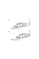
- the drawing It is a schematic diagram of a driving support device, It is a figure showing the situation where the vehicle approaches the wall on the uphill road, It is a figure showing the situation where the vehicle approaches the wall across the step, It is a flowchart which shows the process which concerns on embodiment.
- the driving assistance apparatus detects other vehicles, road structures, and the like as objects existing around the vehicle by receiving object detection information from the distance measuring sensor.
- a schematic configuration of a vehicle driving support apparatus according to the present embodiment will be described with reference to FIG.
- the vehicle 10 includes a driving support ECU (Electronic Control Unit) 20 that is a driving support device.
- the vehicle 10 includes a wheel speed sensor 31, an accelerator sensor 32, a brake sensor 33, an acceleration sensor 34, and a distance measuring sensor 35 as sensors.
- Each sensor 31 to 35 is connected to the driving support ECU 20.
- the driving assistance ECU 20 receives the signals from the sensors 31 to 35 and transmits a control signal to the brake 42, thereby performing collision avoidance control.
- the brake 42 functions as a collision avoidance device according to a command from the driving support ECU 20.
- the driving support ECU 20 is equipped with a microcomputer, a wire harness interface, and the like.
- the microcomputer has a known configuration including a CPU (Central Processing Unit), a ROM (Read Only Memory), a RAM (Random Access Memory), an I / O, a CAN (Controller Area Network) communication device, and the like.
- the wheel speed sensor 31 is a pulse detection type that outputs a pulse signal at a predetermined cycle.
- an electromagnetic pickup type that outputs a pulse signal at a predetermined period in accordance with the passage of a plurality of convex portions provided on a rotor that rotates together with the wheel is used.
- the driving assistance ECU 20 receives the detection signal of the wheel speed sensor 31 and calculates the vehicle speed based on the pulse interval of the input detection signal.
- the accelerator sensor 32 is a sensor that detects the amount of depression of the accelerator pedal.
- the driving assistance ECU 20 receives the detection signal of the accelerator sensor 32, obtains a required torque (required air amount), and transmits a control signal to the engine 41 based on the required torque.
- the brake sensor 33 is a sensor that detects the depression amount of the brake pedal.
- the driving assistance ECU 20 receives the detection signal of the brake sensor 33 and transmits a control signal to the brake 42.
- the acceleration sensor 34 senses the acceleration of the vehicle 10 based on the force applied to the sensor itself, and uses, for example, a capacitance type or a piezoresistive type.
- the vehicle 10 is stopped on a flat road surface, and the acceleration in a state in which the gravitational acceleration works perpendicularly to the vehicle 10 is used as a reference. That is, in a state where the vehicle 10 is stopped on the inclined road surface with the inclination direction as the vehicle traveling direction, the acceleration in the traveling direction of the vehicle 10 corresponding to the inclination angle is detected.
- the acceleration detected by the acceleration sensor 34 is input to the driving support ECU 20.
- the distance measuring sensor 35 is an ultrasonic sensor, for example, and has a function of transmitting an ultrasonic wave of 20 to 100 kHz as a search wave and a function of receiving a search wave reflected from an object as a reflected wave.
- four distance measuring sensors 35 are attached to a front portion of the vehicle (for example, a front bumper) in a direction (vehicle width direction) orthogonal to the traveling direction of the vehicle 10 with a predetermined interval.
- the distance measuring sensor 35 includes two center sensors (a first sensor 35a and a second sensor 35b) attached to a target position in the vicinity of the center line 11 of the vehicle 10 and the vehicle. And 10 corner sensors 35c and 35d attached to the left corner and the right corner, respectively.
- the vehicle 10 has a distance measuring sensor 35 attached to the rear part of the vehicle (for example, the rear bumper). However, since the attachment position and function of the sensor are the same as those of the distance measuring sensor 35 in the front part of the vehicle, here. Description is omitted.
- the driving support ECU 20 detects the presence or absence of an object around the vehicle 10 based on the object detection information received from the distance measuring sensor 35. Specifically, the driving assistance ECU 20 transmits a control signal to the distance measuring sensor 35 and instructs to transmit an exploration wave at every transmission opportunity at a predetermined time interval (for example, every several hundred milliseconds). Subsequently, when the driving assistance ECU 20 receives object detection information from the distance measuring sensor 35, the driving support ECU 20 determines the presence or absence of an object around the vehicle based on the received detection information. If it is determined that an object is present in the forward direction of the vehicle 10, the distance setting unit 23 sets a reference value as an operating distance that is the distance to operate the brake 42 in order to avoid a collision with the object. To do.
- the operation determination unit 24 determines whether or not the distance between the vehicle 10 and the object is smaller than the operation distance, and transmits a command for operating the brake 42 if the distance between the vehicle 10 and the object is smaller than the operation distance. .
- the engine 41 may be simultaneously controlled to suppress the driving force.
- the driving force of the engine 41 is transmitted to the wheels of the vehicle 10 via an automatic transmission.
- a torque converter is employed in the clutch mechanism, and transmission of driving force to the wheels cannot be completely cut off. Therefore, even when the driver does not perform an accelerator operation during low-speed traveling, the driving force from the engine 41 is transmitted to the wheels, and a creep phenomenon occurs.
- the vehicle 10 when the vehicle 10 is traveling at a low speed, an object such as another vehicle, a wall, or a pillar existing at a relatively close distance (for example, within 5 m) from the vehicle 10 is detected by the distance measuring sensor 35.
- the vehicle 10 functions when the vehicle 10 is parked.
- the operation by the driver differs depending on whether or not there is a traveling resistance that suppresses rolling of the wheels. Specifically, the vehicle 10 can be moved by a creep phenomenon on a flat road surface without running resistance. Therefore, when the vehicle 10 is brought close to the object, the driver performs the brake operation without performing the accelerator operation. In this case, if the driver performs an accelerator operation, there is a possibility that the accelerator operation may be mistaken for stepping, so it is necessary to stop the vehicle 10 earlier.
- FIG.2 and FIG.3 As shown in FIG. 2, when the vehicle 10 climbs an inclined road surface 60 (uphill road) and approaches the wall 50, the accelerator 10 is depressed to move the vehicle 10. At this time, if it is determined that the accelerator operation is wrong, the working distance is set larger, and the brake 42 is set in a state where the distance L between the vehicle 10 and the wall 50 is large as shown in FIG. Will be activated.
- the road surface 60 on which the vehicle 10 is located is an uphill road and the driver performs an accelerator operation, if the working distance is set to be smaller than the reference value, a wall as shown in FIG. 50 can be made closer.
- the vehicle 10 when there is a step 61 on the road surface 60, the vehicle 10 temporarily stops when it contacts the step 61 as shown in FIG. At this time, the driver can step on the step 61 as shown in FIG. 3B by depressing the accelerator. Then, by continuing to depress the accelerator, the vehicle 10 can be brought closer to the wall 50 as shown in FIG. At this time, if it is determined that the accelerator operation is mistaken, the working distance is set as a larger value. Therefore, as shown in FIG. 3A and FIG. 3B, the brake 42 operates in a state where the distance L between the vehicle 10 and the wall 50 is large and cannot sufficiently approach the wall 50. In other cases, the step 61 cannot be overcome.
- the resistance determination unit 21 of the driving support ECU 20 determines whether or not there is a running resistance on the road surface 60, and the operation determination unit 22 determines whether or not the accelerator operation by the driver has been performed. To do.
- the distance setting unit 23 sets the working distance to a correction value that is smaller than the reference value, and It is possible to squeeze in.
- the case where the running resistance is present on the road surface 60 mainly includes the case where the vehicle 10 ascends as shown in FIG. 2 and the case where the step 61 exists on the road surface 60 as shown in FIG. Therefore, it is determined by using the detection values of the sensors 31 to 34 whether the running resistance exists.
- the running resistance is the step 61
- the vehicle 10 stops once by contacting the step 61 as described above. Therefore, it is determined that the step 61 exists as the running resistance when the state in which the vehicle 10 cannot move is continued for a predetermined period in spite of detecting the accelerator operation. Note that whether or not the state in which the vehicle 10 cannot move has continued for a predetermined period may be detected by at least one of the detection value of the acceleration sensor 34 and the detection value of the wheel speed sensor 31.
- a threshold is provided for the operation amount (accelerator opening) detected by the accelerator sensor 32, and when the operation amount (accelerator opening) exceeds the threshold, the working distance is set as a reference value. Further, when the vehicle 10 is moved on the uphill road, the driver needs to increase the amount of accelerator operation (accelerator opening) as the slope of the road surface 60 increases. For this reason, the gradient is obtained from the detection value of the acceleration sensor 34, and the threshold value to be compared with the accelerator opening may be set larger as the gradient is larger.
- FIG. 4 is a flowchart showing a series of processing executed by the driving support ECU 20 according to the present embodiment. The process of FIG. 4 is repeatedly executed every predetermined control cycle.
- the operation determination unit 22 determines whether an accelerator operation is performed by the driver (S102). If the accelerator operation is not performed by the driver (S102: NO), it can be said that the driver is not performing an operation of approaching the obstacle, so the working distance is set to the reference value (S106). If the accelerator operation is performed by the driver (S102: YES), the resistance determination unit 21 determines whether or not there is running resistance (S103).
- the distance setting unit 23 sets the working distance to the reference value (S106). If the running resistance exists (S103: YES), it is determined whether or not the accelerator opening is smaller than the threshold (S104). When the accelerator opening is equal to or larger than the threshold (S104: NO), the vehicle 10 may accelerate rapidly or the vehicle speed may become excessive. Therefore, the working distance is set to the reference value (S106). If the accelerator opening is smaller than the threshold value (S104: YES), there is a high possibility that the operation is closer to the driver, so the distance setting unit 23 sets the working distance to a correction value that is smaller than the reference value. Set (S105).
- the working distance is obtained in one of the processes of S105 and S106, it is determined whether or not the distance to the obstacle is smaller than the working distance (S107). If the distance from the obstacle is smaller than the working distance (S107: YES), the brake 42 is actuated to perform the braking control (S108). On the other hand, if the distance to the obstacle is larger than the working distance (S107: NO), the series of processes is terminated as it is.
- the driving support apparatus has the following effects.
- the working distance of the brake 42 is set to a value smaller than the reference value. Therefore, it is possible to suppress the operation of the collision avoidance device from being performed at an early stage in a situation where the driver approaches the object by the accelerator operation. Therefore, driving assistance according to the driver's intention can be made possible.
- the accelerator operation by the driver may be an erroneous operation.
- the operating distance of the brake 42 is not set as a correction value but is set as a reference value. Therefore, when the driver misoperates the accelerator, the brake 42 is operated at an appropriate distance. be able to.
- a threshold is provided for the operation amount (accelerator opening) detected by the accelerator sensor 32, and the operating distance is set to a value smaller than the reference value when the operation amount (accelerator opening) is smaller than the threshold. . Therefore, the working distance can be set small only when the operation by the driver is close to the object.
- the threshold value to be compared with the accelerator opening is set larger.Therefore, in a situation where the road surface gradient is large, it is erroneously determined that the accelerator operation by the driver is wrong. Can be suppressed.
- the working distance is set to be smaller than the reference value when the running resistance exists and the accelerator operation is performed.
- the process of making the working distance smaller than the reference value may be performed even on a flat road. Specifically, on a flat road, the driver does not perform the accelerator operation, but approaches the object by the brake operation. Therefore, the operating distance may be set small by detecting the brake operation.
- the vehicle speed detected by the wheel speed sensor 31 is smaller than the speed corresponding to the accelerator operation amount (accelerator opening) by the driver. Further, even when the vehicle 10 passes over the step 61 of the road surface 60 and does not stop at the step 61 and climbs over the step 61, the vehicle speed detected by the wheel speed sensor 31 is a speed corresponding to the accelerator operation by the driver. Smaller than. Therefore, in the above embodiment, the vehicle speed and the operation amount (accelerator opening) detected by the accelerator sensor 32 are associated with each other, and the actual measured value of the vehicle speed acquired from the wheel speed sensor 31 is greater than the vehicle speed corresponding to the accelerator opening. When it is small, it may be determined that a running resistance exists.
- the case where the running resistance exists is not limited thereto.
- the determination as to whether or not the running resistance exists may be made based on, for example, the relationship between the accelerator opening and the vehicle speed described above.
- the torque converter is used to transmit the driving force from the engine 41 to the wheels, thereby causing the creep phenomenon.
- a continuously variable transmission or the like instead of the torque converter may be employed for power transmission.
- the same effect as in the above embodiment can be obtained as long as it has a function of generating a creep phenomenon. be able to.
- the brake 42 is operated as the collision avoidance device, but a speaker mounted on the vehicle 10 may be used as the collision avoidance device. Specifically, when the distance between the vehicle 10 and the object becomes smaller than the working distance, a warning sound for the driver may be generated to prompt a braking operation by the driver. Note that both the brake 42 and the speaker may be employed as a collision avoidance device. In this case, the working distances of the brake and the speaker may be equal or different.
- the drive source of the vehicle 10 is the engine 41, but the present invention can be similarly applied to a vehicle using a motor as the drive source.
- the driving support ECU 20 which is a driving support device
- a program is stored in a ROM corresponding to a non-transitional tangible recording medium, and this program is executed by a CPU corresponding to a processor of a computer, whereby the driving support device.
- the program may be stored in a non-transitional tangible recording medium other than the ROM (for example, a nonvolatile memory other than the ROM), and the program may be executed by a processor such as a CPU.
- the driving support apparatus may be configured such that a method (for example, a driving support method) corresponding to the program is executed when the program stored in the non-transitional tangible recording medium is executed by the processor.
- each part (for example, the resistance determination part 21, the operation determination part 22, and the distance setting part 23) of the driving assistance ECU 20 provided by the driving assistance device is software recorded in a non-transitional tangible recording medium such as a nonvolatile memory. And a computer executing it, or software only, hardware only, or a combination thereof.
Landscapes
- Engineering & Computer Science (AREA)
- Automation & Control Theory (AREA)
- Transportation (AREA)
- Mechanical Engineering (AREA)
- Physics & Mathematics (AREA)
- General Physics & Mathematics (AREA)
- Human Computer Interaction (AREA)
- Traffic Control Systems (AREA)
- Control Of Driving Devices And Active Controlling Of Vehicle (AREA)
- Regulating Braking Force (AREA)
Abstract
運転支援装置(20)は、車両(10)の進行方向前方に位置する物体との距離に応じて、車両(10)に搭載された衝突回避装置を作動させる。運転支援装置20は、車両(10)の進行方向前方への車輪の転がりを抑制する走行抵抗が存在するか否かを判定する抵抗判定部(21と、車両(10)の運転者によるアクセル操作がなされているか否かを判定する操作判定部(22)と、衝突回避装置を作動させる距離である作動距離を設定する距離設定部(23)と、を備える。距離設定部(23)は、抵抗判定部(21)が、走行抵抗が存在すると判定し、且つ、操作判定部(22)が、アクセル操作がなされていると判定した場合に、走行抵抗が存在しない場合よりも作動距離を小さい値に設定する。
Description
本出願は、2015年6月30日に出願された日本出願番号2015-131132号に基づくもので、ここにその記載内容を援用する。
本開示は、車両の進行方向に存在する物体を検知して車両を制御する、運転支援装置、及びその運転支援装置により実行すされる運転支援方法に関する。
従来、超音波センサ等の測距センサを車両に搭載し、この測距センサを用いて先行車両や歩行者、道路上の構造物等の車両周辺に存在する物体を検知する運転支援装置が提案されている。この運転支援装置は、その測距センサの物体検知結果に基づいて、車両の走行安全性を向上させるための各種制御、例えば、制動装置の作動や、運転者への報知等を行っている。
このような運転支援装置が搭載された車両では、駐車時等、運転者が物体へにじり寄りたい場合においても、物体への過度な接近であると判定し、不要な作動を起こすことがある。そのため、運転者の意思に応じて、物体へ接近可能な距離を設定する必要がある。この点、物体との距離の目標値を、運転者が設定可能としたものとして、特許文献1に記載の運転支援装置がある。
特許文献1に記載の運転支援装置では、運転者が距離の目標値を入力可能であるものの、その距離は一律に設定されるものであり、また、運転者が状況を判断して距離を入力するとも限らない。そのため、必ずしも、運転者の操作意思に応じた運転支援が可能であるとはいえない。
本開示の主たる目的は、運転者の操作に応じて、衝突回避装置を作動させる距離を適切に設定することができる運転支援装置、及び運転支援方法を提供することにある。
本開示の第一の態様は、車両の進行方向前方に位置する物体との距離に応じて、前記車両に搭載された衝突回避装置を作動させる運転支援装置であって、前記車両の前記進行方向前方への車輪の転がりを抑制する走行抵抗が存在するか否かを判定する抵抗判定部と、前記車両の運転者によるアクセル操作がなされているか否かを判定する操作判定部と、前記衝突回避装置を作動させる距離である作動距離を設定する距離設定部と、を備え、前記距離設定部は、前記抵抗判定部が、前記走行抵抗が存在すると判定し、且つ、前記操作判定部が、前記アクセル操作がなされていると判定した場合に、前記走行抵抗が存在しない場合よりも前記作動距離を小さい値に設定する。
平坦な路面では、クリープ現象により車両を移動させることが可能である。そのため、車両を物体に接近させる際に、運転者はアクセル操作を行わず、ブレーキ操作を行うこととなる。この場合では、運転者がアクセル操作を行えば、そのアクセル操作は踏み間違えの可能性があるため、より早く車両を停止させる必要がある。一方で、登坂路であったり、段差が存在していたりする等、路面に走行抵抗が存在する場合には、クリープ現象により車両を移動させることができない。ゆえに、運転者はアクセル操作により車両を移動させて、物体に接近させることとなる。このとき、平坦な路面である場合と同様に、運転者のアクセル操作を踏み間違えであると判定すれば、衝突回避装置の作動により車両を物体に接近させることができないため、運転者は煩わしさを感ずることとなる。
この点、上記構成では、走行抵抗が存在し、且つ、運転者によるアクセル操作がなされていると判定した場合に、衝突回避装置を作動させる距離である作動距離をより小さい値に設定している。これにより、運転者がアクセル操作により物体へ接近させる状況で、衝突回避装置の作動が早期に行われることを抑制することができる。ゆえに、運転者の意思に応じた運転支援を可能とすることができる。
本開示についての上記目的およびその他の目的、特徴や利点は、添付の図面を参照しながら下記の詳細な記述により、より明確になる。その図面は、
運転支援装置の概略図であり、
車両が登坂路で壁に接近する状況を示す図であり、
車両が段差を越えて壁に接近する状況を示す図であり、
実施形態に係る処理を示すフローチャートである。
以下、車両に搭載される運転支援装置として具体化した実施形態について、図面を参照しつつ説明する。本実施形態に係る運転支援装置は、測距センサから物体の検知情報を受信することにより、車両の周囲に存在する物体として例えば他の車両や道路構造物等を検知する。まず、本実施形態に係る車両の運転支援装置の概略構成について図1を用いて説明する。
図1において、車両10は、運転支援装置である運転支援ECU(Electronic Control Unit)20を備えている。車両10は、センサとして、車輪速センサ31、アクセルセンサ32、ブレーキセンサ33、加速度センサ34及び測距センサ35を備えている。各センサ31~35は、運転支援ECU20に接続されている。運転支援ECU20は、各センサ31~35からの信号を受信し、ブレーキ42へ制御信号を送信することにより、衝突回避制御を実施する。なお、このとき、ブレーキ42は、運転支援ECU20からの指令により衝突回避装置として機能することとなる。
運転支援ECU20は、マイコン、ワイヤハーネスのインタフェースなどを搭載している。上記マイコンは、CPU(Central Processing Unit)、ROM(Read Only Memory)、RAM(Random Access Memory)、I/O、及び、CAN(Controller Area Network)通信装置等を備えた公知の構成を有する。
車輪速センサ31は、所定周期でパルス信号を出力するパルス検出式である。本実施形態では、車輪と共に回転するロータに設けられた複数の凸部の通過に応じて、所定周期でパルス信号を出力する電磁ピックアップ式を用いている。運転支援ECU20は、車輪速センサ31の検出信号を受信し、入力された検出信号のパルス間隔に基づいて車速を算出する。
アクセルセンサ32は、アクセルペダルの踏込量を検出するセンサである。運転支援ECU20は、アクセルセンサ32の検出信号を受信して要求トルク(要求空気量)を求め、その要求トルクに基づいてエンジン41へ制御信号を送信する。ブレーキセンサ33は、ブレーキペダルの踏込量を検出するセンサである。運転支援ECU20は、ブレーキセンサ33の検出信号を受信して、ブレーキ42へ制御信号を送信する。
加速度センサ34は、センサ自身に加わる力に基づき車両10の加速度を感知するものであり、例えば静電容量型やピエゾ抵抗型などを用いる。加速度センサ34では、車両10が平坦な路面に停車しており、車両10に対して垂直に重力加速度が働く状態の加速度を基準としている。すなわち、傾斜した路面においてその傾斜方向を車両進行方向として車両10が停車している状態では、その傾斜角度に応じた車両10の進行方向についての加速度が検出されることとなる。加速度センサ34が検出した加速度は、運転支援ECU20へ入力される。
測距センサ35は、例えば超音波センサであり、20~100kHzの超音波を探査波として送信する機能と、物体から反射した探査波を反射波として受信する機能とを有している。本実施形態では、車両前部(例えば前方バンパ)に、車両10の進行方向に直交する方向(車幅方向)に並ぶように、4つの測距センサ35が所定の間隔を開けて取り付けられている。具体的には、測距センサ35は、車両10の中心線11の近傍に中心線11に対して対象位置に取り付けられた2つのセンタセンサ(第1センサ35a,第2センサ35b)と、車両10の左コーナ及び右コーナにそれぞれ取り付けられたコーナセンサ35c,35dとを備えている。なお、車両10には、車両後部(例えば後方バンパ)にも測距センサ35が取り付けられているが、センサの取り付け位置及び機能は車両前部の測距センサ35と同じであるため、ここでは説明を省略する。
運転支援ECU20は、測距センサ35から受信した物体の検知情報に基づいて、車両10周辺の物体の有無を検知する。具体的には、運転支援ECU20は、測距センサ35に制御信号を送信し、所定時間間隔(例えば、数百ミリ秒間隔)の送信機会ごとに探査波を送信するように指令する。続いて、運転支援ECU20が、測距センサ35から物体の検知情報を受信すると、その受信した検知情報に基づいて、車両周辺の物体の有無を判断する。そして、車両10の進行方向前方に物体が存在すると判断した場合には、距離設定部23がその物体との衝突を回避すべく、ブレーキ42を作動させる距離である作動距離として、基準値を設定する。作動判定部24は、車両10と物体との距離が作動距離よりも小さいか否かを判定し、車両10と物体との距離が作動距離よりも小さければ、ブレーキ42を作動させる指令を送信する。このときに、エンジン41に対して駆動力を抑制する制御を同時に行うものとしてもよい。
このエンジン41の駆動力は、オートマチックトランスミッションを介して、車両10の車輪へ伝達される。このオートマチックトランスミッションでは、クラッチ機構にトルクコンバータを採用しており、車輪への駆動力の伝達を完全に切断することができない。そのため、低速走行時に運転者によるアクセル操作がなされていない場合でも、エンジン41からの駆動力が車輪へ伝達され、クリープ現象が生ずる。
なお、本実施形態では、車両10が低速走行している場合において、車両10から比較的近い距離(例えば5m以内)に存在する他車両、壁、柱等の物体を測距センサ35により検知し、その物体に対する衝突回避を行うものとしており、例えば車両10の駐車時において機能する。
車両10が低速走行する際に、車輪の転がりを抑制する走行抵抗が存在するか否かにより、運転者による操作は異なるものとなる。具体的には、走行抵抗の無い平坦な路面では、クリープ現象により車両10を移動させることが可能である。そのため、車両10を物体に接近させる際に、運転者はアクセル操作を行わず、ブレーキ操作を行うこととなる。この場合では、運転者がアクセル操作を行えば、そのアクセル操作は踏み間違えの可能性があるため、より早く車両10を停止させる必要がある。
一方で、路面に走行抵抗が存在する場合には、クリープ現象により車両10を移動させることができない。この走行抵抗が存在する場合について、図2及び図3を用いて説明する。図2に示すように車両10が傾斜した路面60(登坂路)を登坂して壁50に接近する場合、アクセルを踏み込んで車両10を移動させることとなる。このとき、そのアクセル操作が踏み間違えであると判定すれば、作動距離がより大きく設定されてしまい、図2(a)に示すように車両10と壁50との距離Lが大きい状態でブレーキ42が作動されることとなる。この点、車両10が位置する路面60が登坂路である場合に、運転者によるアクセル操作がなされたら、作動距離を基準値よりも小さく設定すれば、図2(b)に示すように、壁50に対してより接近させることができるようになる。
同様に、路面60に段差61が存在する場合には、図3(a)で示すように、車両10は段差61に接触した際に一旦停止する。このとき、運転者がアクセルを踏み込むことにより、図3(b)に示すように、段差61に乗り上げることが可能となる。そして、アクセルの踏込を継続することで、図3(c)に示すように、車両10を壁50に接近させることが可能となる。このとき、アクセル操作を踏み間違えであると判定すれば、作動距離がより大きな値として設定される。そのため、図3(a)や図3(b)に示すように、車両10と壁50との距離Lが大きい状態でブレーキ42が作動し、壁50に対して十分に接近させることができない場合や、段差61を乗り越えることができない場合が起こり得る。
そこで、本実施形態では、運転支援ECU20の抵抗判定部21が、路面60に走行抵抗が存在するか否かを判定し、操作判定部22が、運転者によるアクセル操作がなされたか否かを判定する。そして、路面60に走行抵抗が存在し、且つ、運転者によるがアクセル操作がなされたと判定した場合、距離設定部23は作動距離を基準値よりも小さい値である補正値に設定し、物体へのにじり寄りを可能とする。
路面60に走行抵抗が存在する場合とは、主に、図2で示したような車両10が登坂する場合と、図3で示したような路面60に段差61が存在する場合とがある。そこで、各センサ31~34の検出値を用いて、走行抵抗が存在しているか否かを判定する。
具体的には、車両10が登坂する場合については、車両10が停止している状態から運転者によるアクセル操作により移動を開始した場合には、停止した状態での加速度センサ34の検出値により登坂路であると判定し、その判定結果を保持すればよい。また、車輪速センサ31の検出値の時間微分値と、加速度センサ34の検出値とを用いて登坂路であるか否かを判定してもよい。
走行抵抗が段差61である場合には、上述したとおり、車両10は段差61に接触することにより一旦停止する。そのため、アクセル操作を検出したにもかかわらず、車両10が移動できない状態が所定期間継続した場合に、走行抵抗として段差61が存在すると判定する。なお、車両10が移動できない状態が所定期間継続したか否かは、加速度センサ34の検出値及び車輪速センサ31の検出値の少なくとも一方により検出すればよい。
ところで、走行抵抗が存在する場合に運転者による過剰なアクセル操作がなされた場合には、車両10が物体に接触するおそれが高まる。そのため、アクセルセンサ32が検出した操作量(アクセル開度)に対して閾値を設け、操作量(アクセル開度)が閾値を超えた場合には、作動距離を基準値とする。また、登坂路で車両10を移動させるうえで、路面60の傾斜が大きいほど、運転者はアクセルの操作量(アクセル開度)を大きくする必要がある。そのため、加速度センサ34の検出値により勾配を求め、その勾配が大きいほど、アクセル開度と比較する閾値を大きく設定すればよい。
図4は、本実施形態に係る運転支援ECU20が実行する一連の処理を示すフローチャートである。図4の処理は、所定の制御周期ごとに繰り返し実行される。
まず、物体(障害物)を検出したか否かを判定する(S101)。障害物を検出しない場合(S101:NO)、ブレーキ42を作動させる必要がないため、一連の処理を終了する。障害物を検出した場合(S101:YES)、操作判定部22が運転者によるアクセル操作がなされているか否かを判定する(S102)。運転者によるアクセル操作がなされていなければ(S102:NO)、運転者は障害物に対してにじり寄る操作をしていないといえるため、作動距離を基準値に設定する(S106)。運転者によるアクセル操作がなされていれば(S102:YES)、抵抗判定部21は走行抵抗が存在するか否かを判定する(S103)。
走行抵抗が存在していなければ(S103:NO)、にじり寄りにアクセル操作は不要であるため、運転者によるアクセルの踏み間違えである可能性がある。そのため、距離設定部23は、作動距離を基準値に設定する(S106)。走行抵抗が存在していれば(S103:YES)、アクセル開度が閾値よりも小さいか否かを判定する(S104)。アクセル開度が閾値以上である場合(S104:NO)、車両10が急加速したり、車速が過剰なものとなったりする可能性がある。そのため、作動距離を基準値に設定する(S106)。アクセル開度が閾値よりも小さければ(S104:YES)、運転者によるにじり寄りの操作である可能性が高いため、距離設定部23は、作動距離を基準値よりも小さい値である補正値に設定する(S105)。
S105の処理及びS106の処理の一方で、作動距離が求まれば、障害物との距離が作動距離よりも小さいか否かを判定する(S107)。障害物との距離が作動距離よりも小さければ(S107:YES)、ブレーキ42を作動させて制動制御を行う(S108)。一方、障害物との距離が作動距離よりも大きければ(S107:NO)、そのまま一連の処理を終了する。
上記構成により、本実施形態に係る運転支援装置は、以下の効果を奏する。
・走行抵抗が存在し、且つ、運転者によるアクセル操作がなされていると判定した場合に、ブレーキ42の作動距離を基準値よりも小さい値に設定している。これにより、運転者がアクセル操作により物体へ接近させる状況で、衝突回避装置の作動が早期に行われることを抑制することができる。ゆえに、運転者の意思に応じた運転支援を可能とすることができる。
・走行抵抗が存在しない場合には、運転者によるアクセル操作は誤操作である可能性がある。上記構成では、走行抵抗が存在しない場合には、ブレーキ42の作動距離を補正値とせず基準値としているため、運転者によるアクセルの誤操作が生じた場合に、適切な距離でブレーキ42を作動させることができる。
・走行抵抗が存在する場合でも、運転者によるアクセル操作が過剰なものであれば、車両10が急加速し、物体と接触する可能性がある。上記構成では、アクセルセンサ32が検出した操作量(アクセル開度)に閾値を設け、操作量(アクセル開度)が閾値よりも小さい場合に作動距離を基準値よりも小さい値に設定している。ゆえに、運転者による操作が物体へのにじり寄りである場合に限定して、作動距離を小さく設定することができる。
・登坂路で車両10を移動させるうえで、路面の勾配が大きいほど、アクセル開度を大きく設定する必要がある。上記構成では、路面の勾配が大きいほど、アクセル開度と比較する閾値を大きく設定しているため、路面の勾配が大きい状況において、運転者によるアクセル操作が踏み間違えであると誤判定することを抑制することができる。
<変形例>
・上記実施形態では、走行抵抗が存在しており、且つアクセル操作がなされている場合に作動距離を基準値よりも小さくするものとした。この点、作動距離を基準値よりも小さくする処理を平坦路においても行ってもよい。具体的には、平坦路では運転者はアクセル操作を行わず、ブレーキ操作により物体に接近するため、ブレーキ操作を検出することにより、作動距離を小さく設定するものとすればよい。
・上記実施形態では、走行抵抗が存在しており、且つアクセル操作がなされている場合に作動距離を基準値よりも小さくするものとした。この点、作動距離を基準値よりも小さくする処理を平坦路においても行ってもよい。具体的には、平坦路では運転者はアクセル操作を行わず、ブレーキ操作により物体に接近するため、ブレーキ操作を検出することにより、作動距離を小さく設定するものとすればよい。
・車両10が登坂路を走行する場合、車輪速センサ31により検出される車速は、運転者によるアクセルの操作量(アクセル開度)に対応した速度よりも小さくなる。また、車両10が路面60の段差61を越えるうえで、段差61で停止せずにその段差61を乗り越えるとしても、車輪速センサ31により検出される車速は、運転者によるアクセル操作に対応した速度よりも小さくなる。そこで、上記実施形態において、車速とアクセルセンサ32が検出した操作量(アクセル開度)とを対応付けておき、車輪速センサ31から取得した車速の実測値がアクセル開度に対応した車速よりも小さい場合に、走行抵抗が存在するものと判定してもよい。
・上記実施形態では、走行抵抗が存在する場合の例として、登坂路である場合と、路面に段差がある場合とを提示したが、走行抵抗が存在する場合とは、これらに限られない。例えば、非舗装路である場合や、路面に小石や砂利が散乱している場合等では、クリープ現象により走行できないことがある。このような場合でも、上記実施形態と同様に、走行抵抗が存在すると判定するものとしてもよい。なお、この場合に、走行抵抗が存在するか否かの判定については、例えば、上述した、アクセル開度と車速との関係により判定するものとすればよい。
・上記実施形態では、エンジン41から車輪へ駆動力を伝達するためにトルクコンバータを用いており、それによりクリープ現象が生ずるものとした。この点、トルクコンバータではなく無段変速機等を動力の伝達に採用してもよい。加えて、エンジン41から車輪への駆動力の伝達を遮断することができるものであっても、クリープ現象を発生させる機能を持たせてあるものであれば、上記実施形態と同様の効果を得ることができる。
・上記実施形態では、衝突回避装置としてブレーキ42を作動させるものとしたが、車両10に搭載されたスピーカを衝突回避装置として利用してもよい。具体的には、車両10と物体との距離が作動距離よりも小さくなったときに、運転者に対する警告音を発生させ、運転者よる制動操作を促すものとすればよい。なお、ブレーキ42とスピーカとを共に衝突回避装置として採用してもよい。この場合には、ブレーキ及びスピーカについて、作動距離を等しいものとしてもよいし、異なるものとしてもよい。
・上記実施形態では、車両10の駆動源をエンジン41としたが、モータを駆動源とする車両にも同様に適用することができる。
上記実施形態では、運転支援装置である運転支援ECU20において、非遷移的実体的記録媒体に相当するROMにプログラムが格納され、このプログラムをコンピュータのプロセッサに相当するCPUが実行することにより運転支援装置の各機能を実現しているが、ROM以外の非遷移的実体的記録媒体(例えば、ROM以外の不揮発性メモリ)にプログラムが格納され、このプログラムをCPU等のプロセッサが実行する構成でもよい。この場合、運転支援装置において、非遷移的実体的記録媒体に格納されたプログラムがプロセッサにより実行されることにより、このプログラムに対応する方法(例えば、運転支援方法)が実行される構成でもよい。
また、運転支援装置が実行する各機能の一部又は全部を、一つあるいは複数の集積回路(すなわち、IC)等によりハードウェア的に構成してもよい。さらに、運転支援装置が提供する運転支援ECU20の各部(例えば、抵抗判定部21、操作判定部22、距離設定部23)は、不揮発性メモリ等の非遷移的実体的記録媒体に記録されたソフトウェアおよびそれを実行するコンピュータ、またはソフトウェアのみ、またはハードウェアのみ、あるいはそれらの組合せによって提供してもよい。
本開示は、実施例に準拠して記述されたが、本開示は当該実施例や構造に限定されるものではないと理解される。本開示は、様々な変形例や均等範囲内の変形をも包含する。加えて、様々な組み合わせや形態、さらには、それらの一要素のみ、それ以上、あるいはそれ以下、を含む他の組み合わせや形態をも、本開示の範疇や思想範囲に入るものである。
Claims (8)
- 車両(10)の進行方向前方に位置する物体との距離に応じて、前記車両に搭載された衝突回避装置を作動させる運転支援装置(20)であって、
前記車両の前記進行方向前方への車輪の転がりを抑制する走行抵抗が存在するか否かを判定する抵抗判定部(21)と、
前記車両の運転者によるアクセル操作がなされているか否かを判定する操作判定部(22)と、
前記衝突回避装置を作動させる距離である作動距離を設定する距離設定部(23)と、を備え、
前記距離設定部は、前記抵抗判定部が、前記走行抵抗が存在すると判定し、且つ、前記操作判定部が、前記アクセル操作がなされていると判定した場合に、前記走行抵抗が存在しない場合よりも前記作動距離を小さい値に設定する、運転支援装置。 - 前記抵抗判定部は、前記車両が登坂路を走行する場合に、前記走行抵抗が存在すると判定する、請求項1に記載の運転支援装置。
- 前記抵抗判定部は、前記車両が走行する路面に段差が存在する場合に、前記走行抵抗が存在すると判定する、請求項1に記載の運転支援装置。
- 前記抵抗判定部は、前記車両の速度と前記アクセル操作の操作量を取得し、取得した前記速度が取得した前記操作量に基づく速度よりも小さい場合に、走行抵抗が存在すると判定する、請求項1~3のいずれか1項に記載の運転支援装置。
- 前記抵抗判定部は、前記車両の進行方向への加速度に基づいて、走行抵抗が存在するか否かを判定する、請求項1又は2に記載の運転支援装置。
- 前記距離設定部は、前記アクセル操作の操作量を取得し、その操作量が閾値よりも小さい場合に、前記作動距離を前記走行抵抗が存在しない場合よりも小さい値に設定する、請求項1~5のいずれか1項に記載の運転支援装置。
- 前記距離設定部は、前記車両が走行する路面の勾配を取得し、その勾配が大きいほど、前記閾値を大きく設定する、請求項6に記載の運転支援装置。
- 車両(10)の進行方向前方に位置する物体との距離に応じて、前記車両に搭載された衝突回避装置を作動させる運転支援装置(20)が実行する運転支援方法であって、
前記車両の前記進行方向前方への車輪の転がりを抑制する走行抵抗が存在するか否かを判定する抵抗判定ステップと、
前記車両の運転者によるアクセル操作がなされているか否かを判定する操作判定ステップと、
前記衝突回避装置を作動させる距離である作動距離を設定する距離設定ステップと、を実行し、
前記距離設定ステップでは、前記抵抗判定ステップで、前記走行抵抗が存在すると判定し、且つ、前記操作判定ステップで、前記アクセル操作がなされていると判定した場合に、前記走行抵抗が存在しない場合よりも前記作動距離を小さい値に設定する、運転支援方法。
Priority Applications (3)
| Application Number | Priority Date | Filing Date | Title |
|---|---|---|---|
| CN201680038806.7A CN107848528B (zh) | 2015-06-30 | 2016-06-21 | 驾驶辅助装置以及驾驶辅助方法 |
| US15/740,617 US11001255B2 (en) | 2015-06-30 | 2016-06-21 | Driving assistance apparatus and driving assistance method |
| DE112016003005.3T DE112016003005B4 (de) | 2015-06-30 | 2016-06-21 | Fahrunterstützungsvorrichtung und fahrunterstützungsverfahren |
Applications Claiming Priority (2)
| Application Number | Priority Date | Filing Date | Title |
|---|---|---|---|
| JP2015-131132 | 2015-06-30 | ||
| JP2015131132A JP6654820B2 (ja) | 2015-06-30 | 2015-06-30 | 運転支援装置、及び運転支援方法 |
Publications (1)
| Publication Number | Publication Date |
|---|---|
| WO2017002669A1 true WO2017002669A1 (ja) | 2017-01-05 |
Family
ID=57608822
Family Applications (1)
| Application Number | Title | Priority Date | Filing Date |
|---|---|---|---|
| PCT/JP2016/068391 Ceased WO2017002669A1 (ja) | 2015-06-30 | 2016-06-21 | 運転支援装置、及び運転支援方法 |
Country Status (5)
| Country | Link |
|---|---|
| US (1) | US11001255B2 (ja) |
| JP (1) | JP6654820B2 (ja) |
| CN (1) | CN107848528B (ja) |
| DE (1) | DE112016003005B4 (ja) |
| WO (1) | WO2017002669A1 (ja) |
Cited By (1)
| Publication number | Priority date | Publication date | Assignee | Title |
|---|---|---|---|---|
| CN109677412A (zh) * | 2017-10-18 | 2019-04-26 | 现代自动车株式会社 | 用于在环境友好车辆中控制爬行扭矩的装置和方法 |
Families Citing this family (38)
| Publication number | Priority date | Publication date | Assignee | Title |
|---|---|---|---|---|
| JP7172362B2 (ja) * | 2018-09-26 | 2022-11-16 | 株式会社アドヴィックス | 車両の路面段差判定装置 |
| JP2021024539A (ja) * | 2019-08-09 | 2021-02-22 | トヨタ自動車株式会社 | 運転支援装置 |
| JP7327171B2 (ja) | 2020-01-08 | 2023-08-16 | トヨタ自動車株式会社 | 車両用電子ミラーシステム |
| JP7234966B2 (ja) | 2020-02-13 | 2023-03-08 | トヨタ自動車株式会社 | 降車支援装置 |
| JP7084443B2 (ja) * | 2020-03-19 | 2022-06-14 | 本田技研工業株式会社 | 車両制御装置および車両 |
| JP7549941B2 (ja) * | 2021-03-17 | 2024-09-12 | パナソニックオートモーティブシステムズ株式会社 | 運転支援装置および運転支援方法 |
| JP7540420B2 (ja) | 2021-10-26 | 2024-08-27 | トヨタ自動車株式会社 | 誤発進抑制装置 |
| JP7616513B2 (ja) * | 2021-12-17 | 2025-01-17 | トヨタ自動車株式会社 | 運転支援装置、運転支援方法及びプログラム |
| JP7569015B2 (ja) | 2021-12-27 | 2024-10-17 | トヨタ自動車株式会社 | 降車支援装置 |
| JP7528960B2 (ja) | 2022-01-11 | 2024-08-06 | トヨタ自動車株式会社 | 運転支援装置 |
| JP7559777B2 (ja) | 2022-01-14 | 2024-10-02 | トヨタ自動車株式会社 | 加速抑制装置 |
| JP7639725B2 (ja) | 2022-02-04 | 2025-03-05 | トヨタ自動車株式会社 | 運転支援装置 |
| JP7602210B2 (ja) | 2022-02-16 | 2024-12-18 | トヨタ自動車株式会社 | 判定装置、判定方法及び、プログラム |
| JP2024014381A (ja) | 2022-07-22 | 2024-02-01 | トヨタ自動車株式会社 | 車両制御方法、車両制御装置、及び車両制御プログラム |
| JP7694502B2 (ja) | 2022-08-23 | 2025-06-18 | トヨタ自動車株式会社 | 車両 |
| JP2024034046A (ja) | 2022-08-31 | 2024-03-13 | トヨタ自動車株式会社 | 運転支援装置、運転支援方法、及び運転支援プログラム |
| JP2024042317A (ja) | 2022-09-15 | 2024-03-28 | トヨタ自動車株式会社 | 運転支援装置、運転支援方法、及び運転支援プログラム |
| JP2024043130A (ja) | 2022-09-16 | 2024-03-29 | トヨタ自動車株式会社 | 周辺画像表示装置、周辺画像表示方法及び周辺画像表示プログラム |
| JP2024044213A (ja) | 2022-09-20 | 2024-04-02 | トヨタ自動車株式会社 | 車両用表示制御装置 |
| JP2024050120A (ja) | 2022-09-29 | 2024-04-10 | トヨタ自動車株式会社 | 運転支援装置、運転支援方法、及び、運転支援プログラム |
| JP7748028B2 (ja) | 2022-09-30 | 2025-10-02 | トヨタ自動車株式会社 | 運転支援装置、運転支援方法及びプログラム |
| JP7732434B2 (ja) | 2022-10-12 | 2025-09-02 | トヨタ自動車株式会社 | 車両用画像表示システム、車両用画像表示方法及びプログラム |
| JP7700771B2 (ja) | 2022-10-26 | 2025-07-01 | トヨタ自動車株式会社 | 運転支援装置、運転支援方法、及びプログラム |
| JP2024067217A (ja) | 2022-11-04 | 2024-05-17 | トヨタ自動車株式会社 | 衝突被害軽減装置 |
| JP7823547B2 (ja) | 2022-11-29 | 2026-03-04 | トヨタ自動車株式会社 | 運転支援装置 |
| JP2024081274A (ja) | 2022-12-06 | 2024-06-18 | トヨタ自動車株式会社 | 車両周辺監視装置、車両周辺監視方法及び車両周辺監視プログラム |
| JP7832594B2 (ja) | 2023-02-01 | 2026-03-18 | トヨタ自動車株式会社 | 降車支援装置 |
| JP2024109318A (ja) | 2023-02-01 | 2024-08-14 | トヨタ自動車株式会社 | 運転支援装置 |
| JP2024131362A (ja) | 2023-03-16 | 2024-09-30 | トヨタ自動車株式会社 | 赤外線投光制御装置、赤外線投光制御方法及び赤外線投光制御プログラム |
| JP7839460B2 (ja) | 2023-03-22 | 2026-04-02 | トヨタ自動車株式会社 | 運転支援装置及び運転支援プログラム |
| JP7806751B2 (ja) | 2023-04-05 | 2026-01-27 | トヨタ自動車株式会社 | 運転支援装置 |
| JP7852584B2 (ja) | 2023-07-03 | 2026-04-28 | トヨタ自動車株式会社 | 車両制御装置及び車両制御方法 |
| JP2025030672A (ja) * | 2023-08-24 | 2025-03-07 | トヨタ自動車株式会社 | 車両制御装置及び車両制御方法 |
| JP7852599B2 (ja) | 2023-09-25 | 2026-04-28 | トヨタ自動車株式会社 | 車両周辺監視システム |
| JP2025109014A (ja) | 2024-01-11 | 2025-07-24 | トヨタ自動車株式会社 | 車両の情報記録装置 |
| JP2025109032A (ja) | 2024-01-11 | 2025-07-24 | トヨタ自動車株式会社 | 後続車両接近通知装置 |
| JP2025111924A (ja) | 2024-01-18 | 2025-07-31 | トヨタ自動車株式会社 | 車両の制御システム、車両の制御方法及び、プログラム |
| JP2025168027A (ja) | 2024-04-26 | 2025-11-07 | トヨタ自動車株式会社 | 後方車両接近通知装置及び後方車両接近通知装置の通知方法 |
Citations (8)
| Publication number | Priority date | Publication date | Assignee | Title |
|---|---|---|---|---|
| JPH0939754A (ja) * | 1995-08-02 | 1997-02-10 | Nippon Soken Inc | 発進速度制御装置 |
| JP2004050925A (ja) * | 2002-07-18 | 2004-02-19 | Advics:Kk | 駐車補助ブレーキ装置 |
| JP2005170134A (ja) * | 2003-12-09 | 2005-06-30 | Nissan Motor Co Ltd | 車両の停車支援装置 |
| JP2005231588A (ja) * | 2004-02-23 | 2005-09-02 | Nissan Motor Co Ltd | 車両の停車支援装置 |
| JP2006347428A (ja) * | 2005-06-17 | 2006-12-28 | Aisin Seiki Co Ltd | 運転支援装置 |
| JP2008150032A (ja) * | 2001-07-11 | 2008-07-03 | Robert Bosch Gmbh | 車両減速の自動作動方法及びその装置 |
| JP2013129228A (ja) * | 2011-12-20 | 2013-07-04 | Toyota Motor Corp | 車両制御装置 |
| JP2015102032A (ja) * | 2013-11-26 | 2015-06-04 | 本田技研工業株式会社 | 運転支援装置 |
Family Cites Families (5)
| Publication number | Priority date | Publication date | Assignee | Title |
|---|---|---|---|---|
| DE102008012912A1 (de) * | 2008-03-06 | 2009-09-10 | Valeo Schalter Und Sensoren Gmbh | Verfahren und Vorrichtung zur Erkennung einer Berührung eines Bordsteins durch ein Fahrzeug |
| JP5542178B2 (ja) * | 2012-07-18 | 2014-07-09 | 富士重工業株式会社 | 車両の駆動力抑制装置 |
| JP5874603B2 (ja) * | 2012-10-31 | 2016-03-02 | トヨタ自動車株式会社 | 運転支援装置 |
| JP6090065B2 (ja) * | 2013-08-27 | 2017-03-08 | トヨタ自動車株式会社 | 運転支援装置 |
| JP6057957B2 (ja) * | 2013-10-30 | 2017-01-11 | 富士重工業株式会社 | 車両制御装置 |
-
2015
- 2015-06-30 JP JP2015131132A patent/JP6654820B2/ja active Active
-
2016
- 2016-06-21 DE DE112016003005.3T patent/DE112016003005B4/de active Active
- 2016-06-21 US US15/740,617 patent/US11001255B2/en active Active
- 2016-06-21 CN CN201680038806.7A patent/CN107848528B/zh active Active
- 2016-06-21 WO PCT/JP2016/068391 patent/WO2017002669A1/ja not_active Ceased
Patent Citations (8)
| Publication number | Priority date | Publication date | Assignee | Title |
|---|---|---|---|---|
| JPH0939754A (ja) * | 1995-08-02 | 1997-02-10 | Nippon Soken Inc | 発進速度制御装置 |
| JP2008150032A (ja) * | 2001-07-11 | 2008-07-03 | Robert Bosch Gmbh | 車両減速の自動作動方法及びその装置 |
| JP2004050925A (ja) * | 2002-07-18 | 2004-02-19 | Advics:Kk | 駐車補助ブレーキ装置 |
| JP2005170134A (ja) * | 2003-12-09 | 2005-06-30 | Nissan Motor Co Ltd | 車両の停車支援装置 |
| JP2005231588A (ja) * | 2004-02-23 | 2005-09-02 | Nissan Motor Co Ltd | 車両の停車支援装置 |
| JP2006347428A (ja) * | 2005-06-17 | 2006-12-28 | Aisin Seiki Co Ltd | 運転支援装置 |
| JP2013129228A (ja) * | 2011-12-20 | 2013-07-04 | Toyota Motor Corp | 車両制御装置 |
| JP2015102032A (ja) * | 2013-11-26 | 2015-06-04 | 本田技研工業株式会社 | 運転支援装置 |
Cited By (1)
| Publication number | Priority date | Publication date | Assignee | Title |
|---|---|---|---|---|
| CN109677412A (zh) * | 2017-10-18 | 2019-04-26 | 现代自动车株式会社 | 用于在环境友好车辆中控制爬行扭矩的装置和方法 |
Also Published As
| Publication number | Publication date |
|---|---|
| CN107848528A (zh) | 2018-03-27 |
| US20180170368A1 (en) | 2018-06-21 |
| DE112016003005B4 (de) | 2023-04-20 |
| DE112016003005T5 (de) | 2018-03-29 |
| JP2017016305A (ja) | 2017-01-19 |
| US11001255B2 (en) | 2021-05-11 |
| CN107848528B (zh) | 2020-10-27 |
| JP6654820B2 (ja) | 2020-02-26 |
Similar Documents
| Publication | Publication Date | Title |
|---|---|---|
| JP6654820B2 (ja) | 運転支援装置、及び運転支援方法 | |
| JP6502662B2 (ja) | 車両制御装置 | |
| CN109591813B (zh) | 碰撞避免辅助装置 | |
| JP7226348B2 (ja) | 運転支援装置 | |
| KR101939441B1 (ko) | 차량의 브레이크 제어 장치 | |
| CN105492277B (zh) | 驾驶辅助设备 | |
| JP7176415B2 (ja) | 衝突前制御装置 | |
| EP2990273A1 (en) | Parking assist device | |
| JP6155963B2 (ja) | 衝突緩和装置 | |
| JP2022024323A (ja) | 衝突回避支援装置 | |
| JP4671242B2 (ja) | 車両制御装置 | |
| EP4375155A2 (en) | Collision avoidance support apparatus | |
| US10723349B2 (en) | Vehicle control device and control method | |
| JP5550629B2 (ja) | 車両用制御装置 | |
| CN109816991A (zh) | 驾驶辅助设备 | |
| US10864907B2 (en) | Vehicle control device and vehicle control method | |
| US8954250B2 (en) | Vehicular control apparatus and vehicular control method | |
| JP6335848B2 (ja) | 車両制御装置、及び車両制御方法 | |
| JP4692077B2 (ja) | 先行車検出装置 | |
| JP2004110346A (ja) | 車両用運転操作補助装置、車両用運転操作補助方法、およびその方法を適用した車両 | |
| CN115179931A (zh) | 车辆的自动制动方法、装置、车辆及存储介质 | |
| JP2005145241A (ja) | 車両用制動力発生装置 | |
| JP2007069727A (ja) | 走行制御装置 | |
| JP2000219110A (ja) | 車両の制動方法及び装置 | |
| JP2014213803A (ja) | 制動制御装置、制動制御方法、プログラム及び媒体 |
Legal Events
| Date | Code | Title | Description |
|---|---|---|---|
| 121 | Ep: the epo has been informed by wipo that ep was designated in this application |
Ref document number: 16817777 Country of ref document: EP Kind code of ref document: A1 |
|
| WWE | Wipo information: entry into national phase |
Ref document number: 15740617 Country of ref document: US |
|
| WWE | Wipo information: entry into national phase |
Ref document number: 112016003005 Country of ref document: DE |
|
| 122 | Ep: pct application non-entry in european phase |
Ref document number: 16817777 Country of ref document: EP Kind code of ref document: A1 |