WO2017002508A1 - 長尺状光学フィルム、その製造方法、偏光板及び表示装置 - Google Patents
長尺状光学フィルム、その製造方法、偏光板及び表示装置 Download PDFInfo
- Publication number
- WO2017002508A1 WO2017002508A1 PCT/JP2016/066125 JP2016066125W WO2017002508A1 WO 2017002508 A1 WO2017002508 A1 WO 2017002508A1 JP 2016066125 W JP2016066125 W JP 2016066125W WO 2017002508 A1 WO2017002508 A1 WO 2017002508A1
- Authority
- WO
- WIPO (PCT)
- Prior art keywords
- group
- film
- optical film
- carbon atoms
- ring
- Prior art date
Links
- 0 CN=C(*CI)[C@]1C(*)=C(*)C(*)=C(*)C1O Chemical compound CN=C(*CI)[C@]1C(*)=C(*)C(*)=C(*)C1O 0.000 description 3
- ZHTHQVSNBXWQMW-UHFFFAOYSA-N CC(C)(C)c(cc1)ccc1Nc1nc(Nc2cccc(C)c2)nc(Nc2cccc(C)c2)n1 Chemical compound CC(C)(C)c(cc1)ccc1Nc1nc(Nc2cccc(C)c2)nc(Nc2cccc(C)c2)n1 ZHTHQVSNBXWQMW-UHFFFAOYSA-N 0.000 description 1
- LWDRHFZIPIGVQM-UHFFFAOYSA-N Cc(cc1)ccc1Nc1nc(Nc2cccc(C)c2)nc(Nc2cc(C)ccc2)n1 Chemical compound Cc(cc1)ccc1Nc1nc(Nc2cccc(C)c2)nc(Nc2cc(C)ccc2)n1 LWDRHFZIPIGVQM-UHFFFAOYSA-N 0.000 description 1
- NLNNWNAHYRYVPM-UHFFFAOYSA-N Cc1cc(Nc2nc(Nc3c(C)cccc3)nc(Nc3cccc(C)c3)n2)ccc1 Chemical compound Cc1cc(Nc2nc(Nc3c(C)cccc3)nc(Nc3cccc(C)c3)n2)ccc1 NLNNWNAHYRYVPM-UHFFFAOYSA-N 0.000 description 1
- NZWVFDMMWWOKJT-UHFFFAOYSA-N Cc1cc(Nc2nc(Nc3ccccc3OC)nc(Nc3cc(C)ccc3)n2)ccc1 Chemical compound Cc1cc(Nc2nc(Nc3ccccc3OC)nc(Nc3cc(C)ccc3)n2)ccc1 NZWVFDMMWWOKJT-UHFFFAOYSA-N 0.000 description 1
- KQJHEAUPUFGPOR-UHFFFAOYSA-N Cc1cccc(Nc2nc(Nc(cc3)ccc3OC)nc(Nc3cc(C)ccc3)n2)c1 Chemical compound Cc1cccc(Nc2nc(Nc(cc3)ccc3OC)nc(Nc3cc(C)ccc3)n2)c1 KQJHEAUPUFGPOR-UHFFFAOYSA-N 0.000 description 1
- MZVQAFYLFBSLCA-UHFFFAOYSA-N Cc1cccc(Nc2nc(Nc3cc(OC)ccc3)nc(Nc3cccc(C)c3)n2)c1 Chemical compound Cc1cccc(Nc2nc(Nc3cc(OC)ccc3)nc(Nc3cccc(C)c3)n2)c1 MZVQAFYLFBSLCA-UHFFFAOYSA-N 0.000 description 1
- UPRNVVRPPOBKKY-UHFFFAOYSA-N Cc1cccc(Nc2nc(Nc3ccc(C)cc3C)nc(Nc3cccc(C)c3)n2)c1 Chemical compound Cc1cccc(Nc2nc(Nc3ccc(C)cc3C)nc(Nc3cccc(C)c3)n2)c1 UPRNVVRPPOBKKY-UHFFFAOYSA-N 0.000 description 1
- QXVWXRMAWJLLJH-UHFFFAOYSA-N Cc1cccc(Nc2nc(Nc3ccccc3)nc(Nc3cccc(C)c3)n2)c1 Chemical compound Cc1cccc(Nc2nc(Nc3ccccc3)nc(Nc3cccc(C)c3)n2)c1 QXVWXRMAWJLLJH-UHFFFAOYSA-N 0.000 description 1
Images


Classifications
-
- C—CHEMISTRY; METALLURGY
- C08—ORGANIC MACROMOLECULAR COMPOUNDS; THEIR PREPARATION OR CHEMICAL WORKING-UP; COMPOSITIONS BASED THEREON
- C08K—Use of inorganic or non-macromolecular organic substances as compounding ingredients
- C08K5/00—Use of organic ingredients
- C08K5/16—Nitrogen-containing compounds
- C08K5/34—Heterocyclic compounds having nitrogen in the ring
-
- B—PERFORMING OPERATIONS; TRANSPORTING
- B29—WORKING OF PLASTICS; WORKING OF SUBSTANCES IN A PLASTIC STATE IN GENERAL
- B29C—SHAPING OR JOINING OF PLASTICS; SHAPING OF MATERIAL IN A PLASTIC STATE, NOT OTHERWISE PROVIDED FOR; AFTER-TREATMENT OF THE SHAPED PRODUCTS, e.g. REPAIRING
- B29C41/00—Shaping by coating a mould, core or other substrate, i.e. by depositing material and stripping-off the shaped article; Apparatus therefor
- B29C41/24—Shaping by coating a mould, core or other substrate, i.e. by depositing material and stripping-off the shaped article; Apparatus therefor for making articles of indefinite length
-
- B—PERFORMING OPERATIONS; TRANSPORTING
- B29—WORKING OF PLASTICS; WORKING OF SUBSTANCES IN A PLASTIC STATE IN GENERAL
- B29C—SHAPING OR JOINING OF PLASTICS; SHAPING OF MATERIAL IN A PLASTIC STATE, NOT OTHERWISE PROVIDED FOR; AFTER-TREATMENT OF THE SHAPED PRODUCTS, e.g. REPAIRING
- B29C55/00—Shaping by stretching, e.g. drawing through a die; Apparatus therefor
- B29C55/02—Shaping by stretching, e.g. drawing through a die; Apparatus therefor of plates or sheets
- B29C55/04—Shaping by stretching, e.g. drawing through a die; Apparatus therefor of plates or sheets uniaxial, e.g. oblique
-
- C—CHEMISTRY; METALLURGY
- C08—ORGANIC MACROMOLECULAR COMPOUNDS; THEIR PREPARATION OR CHEMICAL WORKING-UP; COMPOSITIONS BASED THEREON
- C08J—WORKING-UP; GENERAL PROCESSES OF COMPOUNDING; AFTER-TREATMENT NOT COVERED BY SUBCLASSES C08B, C08C, C08F, C08G or C08H
- C08J5/00—Manufacture of articles or shaped materials containing macromolecular substances
- C08J5/18—Manufacture of films or sheets
-
- G—PHYSICS
- G02—OPTICS
- G02B—OPTICAL ELEMENTS, SYSTEMS OR APPARATUS
- G02B5/00—Optical elements other than lenses
- G02B5/30—Polarising elements
-
- G—PHYSICS
- G02—OPTICS
- G02B—OPTICAL ELEMENTS, SYSTEMS OR APPARATUS
- G02B5/00—Optical elements other than lenses
- G02B5/30—Polarising elements
- G02B5/3083—Birefringent or phase retarding elements
-
- G—PHYSICS
- G02—OPTICS
- G02F—OPTICAL DEVICES OR ARRANGEMENTS FOR THE CONTROL OF LIGHT BY MODIFICATION OF THE OPTICAL PROPERTIES OF THE MEDIA OF THE ELEMENTS INVOLVED THEREIN; NON-LINEAR OPTICS; FREQUENCY-CHANGING OF LIGHT; OPTICAL LOGIC ELEMENTS; OPTICAL ANALOGUE/DIGITAL CONVERTERS
- G02F1/00—Devices or arrangements for the control of the intensity, colour, phase, polarisation or direction of light arriving from an independent light source, e.g. switching, gating or modulating; Non-linear optics
- G02F1/01—Devices or arrangements for the control of the intensity, colour, phase, polarisation or direction of light arriving from an independent light source, e.g. switching, gating or modulating; Non-linear optics for the control of the intensity, phase, polarisation or colour
- G02F1/13—Devices or arrangements for the control of the intensity, colour, phase, polarisation or direction of light arriving from an independent light source, e.g. switching, gating or modulating; Non-linear optics for the control of the intensity, phase, polarisation or colour based on liquid crystals, e.g. single liquid crystal display cells
- G02F1/133—Constructional arrangements; Operation of liquid crystal cells; Circuit arrangements
- G02F1/1333—Constructional arrangements; Manufacturing methods
- G02F1/1335—Structural association of cells with optical devices, e.g. polarisers or reflectors
- G02F1/13363—Birefringent elements, e.g. for optical compensation
Definitions
- the present invention relates to a long optical film, a manufacturing method thereof, a polarizing plate and a display device. More specifically, the present invention is a long optical film stretched so as to have a slow axis that is inclined with respect to the longitudinal direction, which reduces unevenness in retardation in the width direction and has an appearance (wrinkles, tarmi). The present invention relates to a long optical film having good quality.
- thin films are required for films used in recent liquid crystal display devices.
- an additive is added to a solution casting film forming method as compared with a melt casting film forming method. Therefore, it is particularly suitable for thinning.
- the present invention has been made in view of the above problems and situations, and the solution is to include a cycloolefin resin and a retardation increasing agent, and stretch so as to have a slow axis inclined with respect to the longitudinal direction.
- the present inventor contains a cycloolefin resin and a retardation increasing agent in the process of examining the cause of the above-mentioned problem, and the slow axis in the in-plane direction is 45 with respect to the longitudinal direction.
- the long optical film tilted within a range of ⁇ 10 ° contains a compound having a specific structure, thereby reducing unevenness in retardation in the width direction and good appearance (wrinkles, tarmi). It has been found that a long optical film can be obtained.
- a long optical film containing a cycloolefin resin and a retardation increasing agent and having a slow axis in the in-plane direction tilted within a range of 45 ⁇ 10 ° with respect to the longitudinal direction.
- a long optical film comprising a compound having a structure represented by (1).
- X represents a heteroatom or a carbon atom.
- Q represents an atomic group necessary for forming an aromatic heterocycle together with a nitrogen atom and X.
- R 1 to R 4 are each a hydrogen atom or a substituent. Represents a group.
- the longitudinal direction In contrast, the film is obliquely stretched in a direction within a range of 45 ⁇ 10 °, and the difference between the maximum value and the minimum value of variations in the retardation value Ro in the width direction is adjusted within a range of 0 to 4 nm.
- a polarizing plate comprising an optical film obtained from the long optical film according to item 1 or 2.
- a display device comprising an optical film obtained from the long optical film described in item 1 or item 2.
- a long optical film containing a cycloolefin resin and a retardation increasing agent and stretched so as to have a slow axis inclined with respect to the longitudinal direction It is possible to provide a long optical film that reduces phase difference unevenness and has a good appearance (wrinkles, tarmi).
- cycloolefin resin has less interaction between resins represented by hydrogen bonds due to its molecular structure, so energy applied by heat is likely to be used for resin movement.
- phase difference that is considered to be caused by the ease of movement of the resin, there is a feature that the sensitivity to the temperature is high, and it is considered that the phase difference unevenness is likely to occur due to the temperature variation at the time of oblique stretching.
- the retardation increasing agent increases the in-plane retardation Ro in the unstretched state, it can increase Ro after stretching the film, but does not change the sensitivity to the temperature of the resin.
- a compound having a structure represented by the general formula (1) having a hydroxy group in the vicinity of a nitrogen atom forms an interaction with a cycloolefin resin by the oxygen atom of the hydroxy group, or easily enters between the resins.
- the elimination of the interaction formed between the resin or between the resin and the compound having the structure represented by the general formula (1), or the compound having the structure represented by the general formula (1) It is presumed that there is an effect of lowering the temperature sensitivity when the phase difference of the resin is expressed due to the buffering effect of the compound.
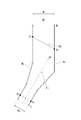
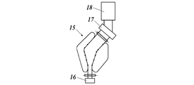
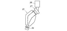
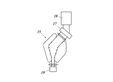
- Schematic which showed an example of the rail pattern of the diagonal stretcher applicable to the manufacturing method of the optical film of this invention Schematic which shows an example (example which extends
- the long optical film of the present invention contains a cycloolefin resin and a retardation increasing agent, and is a long film whose slow axis in the in-plane direction is inclined within a range of 45 ⁇ 10 ° with respect to the longitudinal direction.
- the optical film contains a compound having a structure represented by the general formula (1). This feature is a technical feature common to the claimed invention.
- the effect of the present invention is high in a thin film having a film thickness of 25 ⁇ m or less.
- the method for producing a long optical film according to the present invention comprises preparing a dope containing a cycloolefin resin, a retardation increasing agent and the specific compound, and forming the film by a solution casting film forming method using the dope.
- the film is obliquely stretched in a direction within a range of 45 ⁇ 10 ° with respect to the longitudinal direction, and the difference between the maximum value and the minimum value of the variation of the retardation value Ro in the width direction can be adjusted within a range of 0 to 4 nm. ,preferable.
- the optical film obtained from the long optical film of the present invention is suitably provided in a display device such as a polarizing plate and a liquid crystal display device or an organic electroluminescence display device.
- ⁇ is used to mean that the numerical values described before and after it are included as a lower limit value and an upper limit value.
- the long optical film of the present invention contains a cycloolefin resin and a retardation increasing agent, and is a long film whose slow axis in the in-plane direction is inclined within a range of 45 ⁇ 10 ° with respect to the longitudinal direction.
- the optical film contains a compound having a structure represented by the following general formula (1).
- the manufacturing method of the long optical film of this invention prepares dope containing the compound which has a structure represented by cycloolefin resin, a retardation raising agent, and the said General formula (1), and uses the said dope
- the film is obliquely stretched in a direction within a range of 45 ⁇ 10 ° with respect to the longitudinal direction, and the difference between the maximum value and the minimum value of the variation in the retardation value Ro in the width direction is determined. It is characterized by adjusting within the range of 0 to 4 nm.
- the long optical film manufactured in this way can be used to produce a long circular polarizing plate by laminating the long polarizer so as to match the longitudinal direction.
- the plate is useful, for example, as a polarizing plate for an organic electroluminescence display device, as a circularly polarizing plate with antireflection properties and reduced color unevenness.
- the “long optical film” as used in the present invention refers to a film having a winding length of 100 m or more, preferably 500 m or more, more preferably 1000 m or more, further preferably 3000 m or more, and particularly preferably 5000 m or more. is there.
- optical film has a slow axis inclined with respect to the longitudinal direction.
- optical film has a slow axis inclined with respect to the longitudinal direction.
- X represents a heteroatom or a carbon atom.
- Q represents an atomic group necessary for forming an aromatic heterocycle together with a nitrogen atom and X.
- R 1 to R 4 are each a hydrogen atom or a substituent. Represents a group.
- X represents a hetero atom or a carbon atom, Q represents a group of atoms necessary for forming an aromatic heterocycle together with a nitrogen atom and X, and the aromatic heterocycle may have a substituent. .
- the aromatic heterocycle is generally an unsaturated heterocycle, preferably a heterocycle having the largest number of double bonds.
- the heterocycle is preferably a 5-membered ring, 6-membered ring or 7-membered ring, more preferably a 5-membered ring or 6-membered ring.
- the hetero atom of the heterocyclic ring is preferably N, S or O, and particularly preferably N.
- the aromatic hetero ring is preferably a pyrrole ring, a pyrazole ring, an imidazole ring, a 1,2,3-triazole ring, a 1,2,4-triazole ring, or a 1,3,5-triazine ring. . Of these, a 1,2,3-triazole ring, a 1,2,4-triazole ring, and a 1,3,5-triazine ring are preferable.
- the heterocyclic group may have a substituent, and when a plurality of heterocyclic groups are present, they may be the same or different, and may form a ring.
- substituents of R 1 to R 4 and the substituents of the above heterocyclic group the following can be applied.
- a halogen atom eg, fluorine atom, chlorine atom, bromine atom, iodine atom
- alkyl group preferably an alkyl group having 1 to 30 carbon atoms, eg, methyl group, ethyl group, n-propyl group, isopropyl group, tert- Butyl group, n-octyl group, 2-ethylhexyl group
- cycloalkyl group preferably a substituted or unsubstituted cycloalkyl group having 3 to 30 carbon atoms, for example, cyclohexyl group, cyclopentyl group, 4-n-dodecylcyclohexyl
- a bicycloalkyl group preferably a substituted or unsubstituted bicycloalkyl group having 5 to 30 carbon atoms, that is, a monovalent group obtained by removing one hydrogen atom from a bicycloalkane having 5 to
- al Nyl group preferably a substituted or unsubstituted alkenyl group having 2 to 30 carbon atoms, such as vinyl group, aryl group
- cycloalkenyl group preferably a substituted
- An unsubstituted bicycloalkenyl group preferably a substituted or unsubstituted bicycloalkenyl group having 5 to 30 carbon atoms, that is, a monovalent group in which one hydrogen atom of a bicycloalkene having one double bond is removed, for example, Bicyclo [2,2,1] hept-2-en-1-yl group, bicyclo [2,2,2] oct-2-en-4-yl group), alkynyl (Preferably a substituted or unsubstituted alkynyl group having 2 to 30 carbon atoms, such as ethynyl group or propargyl group), an aryl group (preferably a substituted or unsubstituted aryl group having 6 to 30 carbon atoms, such as a phenyl group, a p-tolyl group, a naphthyl group), a heterocyclic group (preferably a monovalent group obtained by removing one hydrogen atom from
- a 5- or 6-membered aromatic heterocyclic group having 3 to 30 carbon atoms such as 2-furyl group, 2-thienyl group, 2-pyrimidinyl group, 2-benzothiazolyl group
- cyano Group hydroxy group, nitro group, carboxy group, alkoxy group (preferably a substituted or unsubstituted alkoxy group having 1 to 30 carbon atoms, such as methoxy group, ethoxy group, isopropoxy group , Tert-butoxy group, n-octyloxy group, 2-methoxyethoxy group), aryloxy group (preferably a substituted or unsubstituted aryloxy group having 6 to 30 carbon atoms such as phenoxy group, 2-methylphenoxy group) Group, 4-tert-butylphenoxy group, 3-nitrophenoxy group, 2-tetradecanoylaminophenoxy group), silyloxy group (preferably silyloxy group having 3 to 20 carbon atoms, for example, trimethyl
- Finylamino group such as dimethoxyphosphinylamino group, dimethylaminophosphinylamino group Group
- the silyl group preferably a substituted or unsubstituted silyl group having 3 to 30 carbon atoms, and examples thereof include a trimethylsilyl group, tert- butyldimethylsilyl group, a phenyldimethylsilyl group).
- the hetero ring is preferably a 1,2,3-triazole ring, and the benzotriazole-based compound represented by the following general formula (2) It is preferable that
- G 1 represents a hydrogen atom.
- G 2 represents a hydrogen atom, a cyano group, a chlorine atom, a fluorine atom, a —CF 3 group, a —CO—G 3 group, an E 3 SO— group or an E 3 SO 2 — group.
- G 3 is a linear or branched alkyl group having 1 to 24 carbon atoms, a linear or branched alkenyl group having 2 to 18 carbon atoms, a cycloalkyl group having 5 to 12 carbon atoms, It represents a phenylalkyl group having 7 to 15 carbon atoms, a phenyl group, or the phenyl group or phenylalkyl group in which the phenyl ring is substituted by 1 to 4 alkyl groups having 1 to 4 carbon atoms.
- E 1 represents a phenylalkyl group having 7 to 15 carbon atoms, a phenyl group, or the phenyl group in which the phenyl ring is substituted with 1 to 4 alkyl groups having 1 to 4 carbon atoms, or the phenylalkyl group.
- E 2 is a linear or branched alkyl group having 1 to 24 carbon atoms, a linear or branched alkenyl group having 2 to 18 carbon atoms, a cycloalkyl group having 5 to 12 carbon atoms, It represents the phenyl group or phenylalkyl group in which the phenyl ring is substituted by 1 to 3 alkyl groups having 7 to 15 carbon atoms, phenyl group, or 1 to 4 alkyl groups having 1 to 4 carbon atoms.
- E 2 represents one or more —OH groups, —OCOE 11 groups, —OE 4 groups, —NCO groups, —NH 2 groups, —NHCOE 11 groups, —NHE 4 groups or —N (E 4 ).
- E 11 is a hydrogen atom, a linear or branched alkylene group having 1 to 18 carbon atoms, a cycloalkyl group having 5 to 12 carbon atoms, or a linear or branched chain having 2 to 18 carbon atoms.
- An alkenyl group, an aryl group having 6 to 14 carbon atoms, or an aralkyl group having 7 to 15 carbon atoms is represented.
- E 3 represents an alkyl group having 1 to 20 carbon atoms, a hydroxyalkyl group having 2 to 20 carbon atoms, an alkenyl group having 3 to 18 carbon atoms, a cycloalkyl group having 5 to 12 carbon atoms, or 7 to 7 carbon atoms.
- phenylalkyl groups aryl groups having 6 to 10 carbon atoms, or aryl groups substituted by 1 or 2 alkyl groups having 1 to 4 carbon atoms, or 1,1,2,2-tetrahydroperfluoroalkyl
- the compound having the structure represented by the general formula (1) according to the present invention is preferably a compound in which the hetero ring has a 1,3,5-triazine ring, and preferred compounds are the following general compounds: It is a compound represented by Formula (3).
- R 1 is a linear or branched alkyl group having 1 to 12 carbon atoms, a cycloalkyl group having 3 to 8 carbon atoms, an alkenyl group having 3 to 8 carbon atoms, or an aryl having 6 to 18 carbon atoms.
- these alkyl group, cycloalkyl group, alkenyl group, aryl group, alkylaryl group or arylalkyl group are a hydroxy group, a halogen atom, an alkyl group having 1 to 12 carbon atoms or an alkoxy group having 1 to 12 carbon atoms.
- R 2 represents a hydrogen atom, an alkyl group having 1 to 8 carbon atoms or an alkenyl group having 3 to 8 carbon atoms
- R 3 represents at least one hydroxy group, and when not a hydroxy group, represents a hydrogen atom
- R 4 represents a hydrogen atom or —O—R 1 .
- Examples of the linear or branched alkyl group having 1 to 12 carbon atoms represented by R 1 in the general formula (3) according to the present invention include, for example, methyl, ethyl, propyl, isopropyl, butyl, isobutyl, second Linear or branched alkyl groups such as butyl, tert-butyl, amyl, isoamyl, tert-amyl, hexyl, heptyl, n-octyl, isooctyl, tert-octyl, 2-ethylhexyl, nonyl, isononyl, decyl, undecyl, dodecyl Is mentioned.
- Examples of the cycloalkyl group having 3 to 8 carbon atoms represented by R 1 in the general formula (3) include cyclopropyl, cyclopentyl, cyclohexyl, cycloheptyl and the like.
- Examples of the aryl group having 6 to 18 carbon atoms or the alkylaryl group having 7 to 18 carbon atoms represented by R 1 in the general formula (3) include phenyl, naphthyl, 2-methylphenyl, and 3-methylphenyl.
- examples of the alkenyl group having 3 to 8 carbon atoms represented by R 1 and R 2 include unsaturated linear and branched propenyl, butenyl, pentenyl, hexenyl, heptenyl, octenyl. It is mentioned regardless of the position of the bond.
- examples of the alkyl group having 1 to 8 carbon atoms represented by R 2 include methyl, ethyl, propyl, isopropyl, butyl, sec-butyl, tert-butyl, isobutyl, amyl, Tertiary amyl, octyl, tertiary octyl and the like can be mentioned.
- a methyl group is preferable because of its excellent ultraviolet absorbing ability.
- triazine compound represented by the general formula (3) examples include the following exemplified compounds 7 to 17, but are not limited thereto.
- the compound having the structure represented by the general formula (1) may be used alone or in combination of two or more.
- the molecular weight of the compound having the structure represented by the general formula (1) is, when the dry film thickness of the optical film of the present invention is 5 to 50 ⁇ m, It is preferably in the range of 100 to 3000, more preferably in the range of 100 to 800. Within the range of 100 to 800, precipitation of the compound itself and generation of bleed out can be suppressed, and the compound can be uniformly dispersed in the dope.
- the method for adding the compound having the structure represented by the general formula (1) described above is, for example, dissolved in an alcohol such as methanol, ethanol, or butanol, an organic solvent such as methylene chloride, methyl acetate, acetone, dioxolane, or a mixed solvent thereof. Then, it may be added to the dope or directly into the dope composition.
- an organic solvent such as methylene chloride, methyl acetate, acetone, dioxolane, or a mixed solvent thereof.
- the organic solvent one kind of organic solvent may be used alone, or two or more kinds of organic solvents may be mixed and used in an arbitrary ratio.
- the amount of the compound having the structure represented by the general formula (1) is not particularly limited as long as the effects of the present invention are exhibited, but 2 to 20 with respect to the cycloolefin resin from the viewpoint of preventing bleeding out and precipitation. It is preferably in the range of mass%, more preferably in the range of 3 to 10 mass%.
- Cycloolefin resin examples include the following (co) polymers.
- R 1 to R 4 are each independently a hydrogen atom, hydrocarbon group, halogen atom, hydroxy group, ester group, alkoxy group, cyano group, amide group, imide group, silyl group, or polar group ( That is, it is a hydrocarbon group substituted with a halogen atom, a hydroxy group, an ester group, an alkoxy group, a cyano group, an amide group, an imide group, or a silyl group.
- two or more of R 1 to R 4 may be bonded to each other to form an unsaturated bond, a monocycle or a polycycle, and this monocycle or polycycle has a double bond.
- an aromatic ring may be formed.
- R 1 and R 2 , or R 3 and R 4 may form an alkylidene group.
- p and m are integers of 0 or more.
- R 1 and R 3 are a hydrogen atom or a hydrocarbon group having 1 to 10 carbon atoms, more preferably 1 to 4 carbon atoms, particularly preferably 1 to 2 carbon atoms, and R 2 and R 4 are hydrogen atoms.
- R 2 and R 4 represents a polar group having a polarity other than a hydrogen atom and a hydrocarbon group
- m is an integer of 0 to 3
- p is 0 to 3
- Examples of the polar group of the specific monomer include a carboxy group, a hydroxy group, an alkoxycarbonyl group, an aryloxycarbonyl group, an amino group, an amide group, and a cyano group. These polar groups have a linking group such as a methylene group. It may be bonded via.
- a hydrocarbon group in which a divalent organic group having a polarity such as a carbonyl group, an ether group, a silyl ether group, a thioether group, or an imino group is bonded as a linking group can also be exemplified.
- a carboxy group, a hydroxy group, an alkoxycarbonyl group or an aryloxycarbonyl group is preferable, and an alkoxycarbonyl group or an aryloxycarbonyl group is particularly preferable.
- R 2 and R 4 are a polar group represented by the formula — (CH 2 ) nCOOR. It is preferable at the point which has the outstanding adhesiveness.
- R is a hydrocarbon group having 1 to 12 carbon atoms, more preferably 1 to 4 carbon atoms, particularly preferably 1 to 2 carbon atoms, and preferably an alkyl group.
- copolymerizable monomer examples include cycloolefins such as cyclobutene, cyclopentene, cycloheptene, cyclooctene, and dicyclopentadiene.
- the number of carbon atoms of the cycloolefin is preferably 4-20, and more preferably 5-12.
- the cycloolefin resin may be used alone or in combination of two or more.
- the preferred molecular weight of the cycloolefin resin according to the present invention is 0.2 to 5 cm 3 / g, more preferably 0.3 to 3 cm 3 / g, particularly preferably 0.4 to 1.5 cm in terms of intrinsic viscosity [ ⁇ ] inh. 3 / g, and the number average molecular weight (Mn) in terms of polystyrene measured by gel permeation chromatography (GPC) is 8000 to 100,000, more preferably 10,000 to 80,000, particularly preferably 12,000 to 50,000, and the weight average molecular weight. (Mw) is preferably in the range of 20,000 to 300,000, more preferably 30,000 to 250,000, particularly preferably 40,000 to 200,000.
- Inherent viscosity [ ⁇ ] inh, number average molecular weight and weight average molecular weight are within the above ranges, so that the heat resistance, water resistance, chemical resistance, mechanical properties of the cycloolefin resin, and molding as the optical film of the present invention Property is improved.
- the glass transition temperature (Tg) of the cycloolefin resin according to the present invention is usually 110 ° C. or higher, preferably 110 to 350 ° C., more preferably 120 to 250 ° C., and particularly preferably 120 to 220 ° C.
- Tg is less than 110 ° C., it is not preferable because it is deformed by use under a high temperature condition or by secondary processing such as coating or printing.
- Tg exceeds 350 ° C., the molding process becomes difficult, and the possibility that the resin deteriorates due to heat during the molding process increases.
- cycloolefin resin a specific hydrocarbon resin or a known thermoplastic resin described in, for example, JP-A-9-221577 and JP-A-10-287732 is used as long as the effects of the present invention are not impaired.
- Resins, thermoplastic elastomers, rubber polymers, organic fine particles, inorganic fine particles, and the like may be blended, and additives such as specific wavelength dispersing agents, sugar ester compounds, rubber particles, and plasticizers may be included.
- Retardation increasing agent The addition of a retardation increasing agent to the optical film of the present invention compensates for a phase difference that is insufficient when the film is thinned, and avoids an excessive stretching operation to adjust the phase difference. Therefore, it is preferable in order to suppress the cause of contrast reduction due to fine cracks (craze) in the film generated during stretching and the arrangement of foreign matters.
- the retardation increasing agent can be contained, for example, in a proportion of 0.5 to 10% by mass, and more preferably in a proportion of 2 to 6% by mass.
- a retardation increasing agent By adopting a retardation increasing agent, high Ro expression can be obtained at a low draw ratio.
- the type of the retardation increasing agent is not particularly defined, but examples thereof include those made of a disk-like or rod-like compound.
- a compound having at least two aromatic rings can be preferably used as a retardation increasing agent.
- the disk-like retardation increasing agent is preferably used in the range of 0.5 to 10 parts by mass, more preferably in the range of 1 to 8 parts by mass with respect to 100 parts by mass of the cycloolefin resin. It is preferably used in the range of 2 to 6 parts by mass.
- the addition amount of the retardation increasing agent composed of the rod-shaped compound is preferably 0.5 to 10 parts by mass, more preferably 2 to 6 parts by mass with respect to 100 parts by mass of the cycloolefin resin.
- Two or more types of retardation increasing agents may be used in combination.
- the retardation increasing agent preferably has a maximum absorption in the wavelength region of 250 to 400 nm, and preferably has substantially no absorption in the visible region.
- the discotic compound will be described.
- As the discotic compound a compound having at least two aromatic rings can be used.
- aromatic ring includes an aromatic heterocycle in addition to an aromatic hydrocarbon ring.
- the aromatic hydrocarbon ring is particularly preferably a 6-membered ring (that is, a benzene ring).
- the aromatic heterocycle is generally an unsaturated heterocycle.
- the aromatic heterocycle is preferably a 5-membered ring, 6-membered ring or 7-membered ring, more preferably a 5-membered ring or 6-membered ring.
- Aromatic heterocycles generally have the most double bonds.
- a nitrogen atom, an oxygen atom and a sulfur atom are preferable, and a nitrogen atom is particularly preferable.
- aromatic heterocycles include furan ring, thiophene ring, pyrrole ring, oxazole ring, isoxazole ring, thiazole ring, isothiazole ring, imidazole ring, pyrazole ring, furazane ring, triazole ring, pyran ring, pyridine ring , Pyridazine ring, pyrimidine ring, pyrazine ring and 1,3,5-triazine ring.
- aromatic ring a benzene ring, a condensed benzene ring and biphenyls are preferable.
- 1,3,5-triazine ring is preferably used.
- compounds disclosed in JP-A No. 2001-166144 are preferably used.
- the number of carbon atoms of the aromatic ring contained in the retardation developing agent is preferably 2-20, more preferably 2-12, and further preferably 2-8. Most preferably.
- the bonding relationship between two aromatic rings can be classified into (a) when forming a condensed ring, (b) when directly connecting with a single bond, and (c) when connecting via a linking group (for aromatic rings). , Spiro bonds cannot be formed).
- the bond relationship may be any of (a) to (c).
- condensed ring examples include an indene ring, a naphthalene ring, an azulene ring, a fluorene ring, a phenanthrene ring, an anthracene ring, an acenaphthylene ring, a biphenylene ring, a naphthacene ring, Pyrene ring, indole ring, isoindole ring, benzofuran ring, benzothiophene ring, indolizine ring, benzoxazole ring, benzothiazole ring, benzimidazole ring, benzotriazole ring, purine ring, indazole ring, chromene ring, quinoline ring, isoquinoline Ring, quinolidine ring, quinazoline ring, cinnoline ring, quinoxaline ring, phthalazine
- the single bond is preferably a bond between carbon atoms of two aromatic rings.
- Two aromatic rings may be bonded by two or more single bonds to form an aliphatic ring or a non-aromatic heterocyclic ring between the two aromatic rings.
- the linking group in (c) is also preferably bonded to carbon atoms of two aromatic rings.
- the linking group is preferably an alkylene group, an alkenylene group, an alkynylene group, —CO—, —O—, —NH—, —S—, or a combination thereof. Examples of linking groups composed of combinations are shown below. In addition, the relationship between the left and right in the following examples of the linking group may be reversed.
- substituents include halogen atoms (F, Cl, Br, I), hydroxy groups, carboxy groups, cyano groups, amino groups, nitro groups, sulfo groups, carbamoyl groups, sulfamoyl groups, ureido groups, alkyl groups, alkenyls.
- alkynyl group alkynyl group, aliphatic acyl group, aliphatic acyloxy group, alkoxy group, alkoxycarbonyl group, alkoxycarbonylamino group, alkylthio group, alkylsulfonyl group, aliphatic amide group, aliphatic sulfonamido group, aliphatic substituted amino group
- the number of carbon atoms in the alkyl group is preferably 1-8.
- a chain alkyl group is preferable to a cyclic alkyl group, and a linear alkyl group is particularly preferable.
- the alkyl group may further have a substituent (for example, a hydroxy group, a carboxy group, an alkoxy group, an alkyl-substituted amino group).
- Examples of alkyl groups (including substituted alkyl groups) include methyl, ethyl, n-butyl, n-hexyl, 2-hydroxyethyl, 4-carboxybutyl, 2-methoxyethyl and 2-methoxyethyl.
- Each group of a diethylaminoethyl group is included.
- the alkenyl group preferably has 2 to 8 carbon atoms.
- a chain alkenyl group is preferable to a cyclic alkenyl group, and a linear alkenyl group is particularly preferable.
- the alkenyl group may further have a substituent. Examples of the alkenyl group include a vinyl group, an allyl group, and a 1-hexenyl group.
- the number of carbon atoms of the alkynyl group is preferably 2-8.
- a chain alkynyl group is preferable to a cyclic alkynyl group, and a linear alkynyl group is particularly preferable.
- the alkynyl group may further have a substituent. Examples of the alkynyl group include ethynyl group, 1-butynyl group and 1-hexynyl group.
- the number of carbon atoms in the aliphatic acyl group is preferably 1-10.
- Examples of the aliphatic acyl group include an acetyl group, a propanoyl group, and a butanoyl group.
- the number of carbon atoms in the aliphatic acyloxy group is preferably 1-10.
- Examples of the aliphatic acyloxy group include an acetoxy group.
- the number of carbon atoms of the alkoxy group is preferably 1-8.
- the alkoxy group may further have a substituent (for example, an alkoxy group).
- a substituent for example, an alkoxy group.
- Examples of the alkoxy group (including a substituted alkoxy group) include a methoxy group, an ethoxy group, a butoxy group, and a methoxyethoxy group.
- the number of carbon atoms of the alkoxycarbonyl group is preferably 2 to 10.
- Examples of the alkoxycarbonyl group include a methoxycarbonyl group and an ethoxycarbonyl group.
- the number of carbon atoms of the alkoxycarbonylamino group is preferably 2 to 10.
- Examples of the alkoxycarbonylamino group include a methoxycarbonylamino group and an ethoxycarbonylamino group.
- the number of carbon atoms of the alkylthio group is preferably 1-12.
- Examples of the alkylthio group include a methylthio group, an ethylthio group, and an octylthio group.
- the number of carbon atoms of the alkylsulfonyl group is preferably 1-8.
- Examples of the alkylsulfonyl group include a methanesulfonyl group and an ethanesulfonyl group.
- the number of carbon atoms in the aliphatic amide group is preferably 1-10.
- Examples of the aliphatic amide group include acetamide.
- the number of carbon atoms in the aliphatic sulfonamide group is preferably 1-8.
- Examples of the aliphatic sulfonamido group include a methanesulfonamido group, a butanesulfonamido group, and an n-octanesulfonamido group.
- the number of carbon atoms of the aliphatic substituted amino group is preferably 1-10.
- Examples of the aliphatic substituted amino group include a dimethylamino group, a diethylamino group, and a 2-carboxyethylamino group.
- the number of carbon atoms in the aliphatic substituted carbamoyl group is preferably 2 to 10.
- Examples of the aliphatic substituted carbamoyl group include a methylcarbamoyl group and a diethylcarbamoyl group.
- the number of carbon atoms of the aliphatic substituted sulfamoyl group is preferably 1-8.
- Examples of the aliphatic substituted sulfamoyl group include a methylsulfamoyl group and a diethylsulfamoyl group.
- the number of carbon atoms of the aliphatic substituted ureido group is preferably 2 to 10.
- Examples of the aliphatic substituted ureido group include a methylureido group.
- non-aromatic heterocyclic groups examples include piperidino groups and morpholino groups.
- the molecular weight of the retardation developing agent is preferably 300 to 800.
- each R 1 independently represents an aromatic ring or a heterocyclic ring having a substituent in at least one of the ortho position, the meta position, and the para position.
- Each X independently represents a single bond or NR 2 —.
- each R 2 independently represents a hydrogen atom, a substituted or unsubstituted alkyl group, an alkenyl group, an aryl group, or a heterocyclic group.
- the aromatic ring represented by R 1 is preferably a phenyl group or a naphthyl group, and particularly preferably a phenyl group.
- the aromatic ring represented by R 1 may have at least one substituent at any substitution position.
- the substituent include a halogen atom, hydroxy group, cyano group, nitro group, carboxy group, alkyl group, alkenyl group, aryl group, alkoxy group, alkenyloxy group, aryloxy group, acyloxy group, alkoxycarbonyl group, Alkenyloxycarbonyl group, aryloxycarbonyl group, sulfamoyl group, alkyl-substituted sulfamoyl group, alkenyl-substituted sulfamoyl group, aryl-substituted sulfamoyl group, sulfonamide group, carbamoyl, alkyl-substituted carbamo
- the heterocyclic group represented by R 1 preferably has aromaticity.
- the heterocycle having aromaticity is generally an unsaturated heterocycle, preferably a heterocycle having the largest number of double bonds.
- the heterocyclic ring is preferably a 5-membered ring, 6-membered ring or 7-membered ring, more preferably a 5-membered ring or 6-membered ring, and most preferably a 6-membered ring.
- the hetero atom of the heterocyclic ring is preferably a nitrogen atom, a sulfur atom or an oxygen atom, and particularly preferably a nitrogen atom.
- heterocyclic ring having aromaticity a pyridine ring (2-pyridyl or 4-pyridyl as the heterocyclic group) is particularly preferable.
- the heterocyclic group may have a substituent. Examples of the substituent of the heterocyclic group are the same as the examples of the substituent of the aryl moiety.
- the heterocyclic group is preferably a heterocyclic group having a free valence on the nitrogen atom.
- the heterocyclic group having a free valence on the nitrogen atom is preferably a 5-membered ring, 6-membered ring or 7-membered ring, more preferably a 5-membered ring or 6-membered ring, and a 5-membered ring. Is most preferred.
- the heterocyclic group may have a plurality of nitrogen atoms. Further, the heterocyclic group may have a hetero atom other than the nitrogen atom (for example, O, S). Examples of heterocyclic groups having free valences on nitrogen atoms are shown below.
- the alkyl group represented by R 2 may be a cyclic alkyl group or a chain alkyl group, but a chain alkyl group is preferable, and a linear alkyl group is more preferable than a branched chain alkyl group. preferable.
- the alkyl group preferably has 1 to 30 carbon atoms, more preferably 1 to 20, more preferably 1 to 10, still more preferably 1 to 8, and further preferably 1 to 6. Most preferred.
- the alkyl group may have a substituent. Examples of the substituent include a halogen atom, an alkoxy group (for example, methoxy group, ethoxy group) and an acyloxy group (for example, acryloyloxy group, methacryloyloxy group).
- the alkenyl group represented by R 2 may be a cyclic alkenyl group or a chain alkenyl group, but preferably represents a chain alkenyl group, and is a straight chain alkenyl group rather than a branched chain alkenyl group. More preferably it represents a group.
- the number of carbon atoms of the alkenyl group is preferably 2 to 30, more preferably 2 to 20, further preferably 2 to 10, still more preferably 2 to 8, and further preferably 2 to 6 is most preferred.
- the alkenyl group may have a substituent. Examples of the substituent are the same as those of the alkyl group described above.
- the aromatic ring group and heterocyclic group represented by R 2 are the same as the aromatic ring and heterocyclic ring represented by R 1 , and the preferred range is also the same.
- the aromatic ring group and the heterocyclic group may further have a substituent, and examples of the substituent are the same as those of the aromatic ring and heterocyclic ring of R 1 .
- a triphenylene compound represented by the following general formula (II) can also be preferably used.
- R 1 , R 2 , R 3 , R 4 , R 5 and R 6 each independently represent a hydrogen atom or a substituent.
- each of R 1 , R 2 , R 3 , R 4 , R 5 and R 6 is an alkyl group (preferably having 1 to 40 carbon atoms, more preferably 1 to 30 carbon atoms, and particularly preferably carbon number). 1 to 20 alkyl groups such as methyl, ethyl, isopropyl, tert-butyl, n-octyl, n-decyl, n-hexadecyl, cyclopropyl, cyclopentyl, cyclohexyl, etc.
- alkenyl group preferably an alkenyl group having 2 to 40 carbon atoms, more preferably 2 to 30 carbon atoms, particularly preferably 2 to 20 carbon atoms, such as a vinyl group, an allyl group, 2- Butenyl group, 3-pentenyl group and the like
- alkynyl group preferably having 2 to 40 carbon atoms, more preferably 2 to 30 carbon atoms, particularly preferably 2 carbon atoms.
- -20 alkynyl groups such as propargyl group and 3-pentynyl group
- aryl groups preferably having 6 to 30 carbon atoms, more preferably 6 to 20 carbon atoms, particularly preferably 6 to 6 carbon atoms).
- aryl groups such as a phenyl group, a p-methylphenyl group, and a naphthyl group, and a substituted or unsubstituted amino group (preferably having 0 to 40 carbon atoms, more preferably 0 to 30 carbon atoms). And particularly preferably an amino group having 0 to 20 carbon atoms.
- Examples thereof include an unsubstituted amino group, a methylamino group, a dimethylamino group, a diethylamino group, and an anilino group, and an alkoxy group (preferably having a carbon number of 1 to 40, more preferably an alkoxy group having 1 to 30 carbon atoms, particularly preferably 1 to 20 carbon atoms, such as a methoxy group, an ethoxy group, And an aryloxy group (preferably an aryloxy group having 6 to 40 carbon atoms, more preferably 6 to 30 carbon atoms, and particularly preferably 6 to 20 carbon atoms, such as a phenyloxy group, 2-naphthyloxy group and the like), an acyl group (preferably an acyl group having 1 to 40 carbon atoms, more preferably 1 to 30 carbon atoms, particularly preferably 1 to 20 carbon atoms, such as an acetyl group, A benzoyl group, a formyl group, a pival
- Mino group such as methoxycarbonylamino group), aryloxycarbonylamino group (preferably 7 to 40 carbon atoms, more preferably 7 to 30 carbon atoms, particularly preferably 7 to 20 carbon atoms)
- An oxycarbonylamino group such as a phenyloxycarbonylamino group), a sulfonylamino group (preferably having 1 to 40 carbon atoms, more preferably 1 to 30 carbon atoms, and particularly preferably 1 to 20 carbon atoms).
- a sulfonylamino group such as a methanesulfonylamino group and a benzenesulfonylamino group
- a sulfamoyl group preferably having 0 to 40 carbon atoms, more preferably 0 to 30 carbon atoms, and particularly preferably 0 to carbon atoms.
- 20 sulfamoyl groups such as sulfamoyl group, methylsulfur group And carbamoyl group (preferably having 1 to 40 carbon atoms, more preferably 1 to 30 carbon atoms, and particularly preferably 1 to 20 carbon atoms).
- alkylthio group preferably having 1 to 40 carbon atoms, more preferably 1 to 30 carbon atoms, especially Preferably it has 1 to 20 carbon atoms, and examples thereof include methylthio group, ethylthio group, propylthio group, butylthio group, pentylthio group, hexylthio group, heptylthio group, octylthio group and the like, arylthio group (preferably having 6 carbon atoms).
- ⁇ 40 more preferably 6-30 carbon atoms, particularly preferred Is a sulfonyl group (preferably a phenylthio group, etc.), a sulfonyl group (preferably a C1-C40, more preferably a C1-C30, particularly preferably a C1-C20 sulfonyl group).
- a sulfonyl group preferably a phenylthio group, etc.
- a sulfonyl group preferably a C1-C40, more preferably a C1-C30, particularly preferably a C1-C20 sulfonyl group.
- a mesyl group, a tosyl group and the like a sulfinyl group (preferably a sulfinyl group having 1 to 40 carbon atoms, more preferably 1 to 30 carbon atoms, particularly preferably 1 to 20 carbon atoms, A methanesulfinyl group, a benzenesulfinyl group and the like), a ureido group (preferably a ureido group having 1 to 40 carbon atoms, more preferably 1 to 30 carbon atoms, and particularly preferably 1 to 20 carbon atoms).
- phosphoric acid amide group (preferably having 1 to 40 carbon atoms, More preferably, it is a phosphoric acid amide group having 1 to 30 carbon atoms, particularly preferably 1 to 20 carbon atoms, and examples thereof include a diethylphosphoric acid amide group and a phenylphosphoric acid amide group), a hydroxy group, a mercapto group, Halogen atom (for example, fluorine atom, chlorine atom, bromine atom, iodine atom), cyano group, sulfo group, carboxy group, nitro group, hydroxamic acid group, sulfino group, hydrazino group, imino group, heterocyclic group (preferably carbon number) 1 to 30, more preferably 1 to 12 heterocyclic groups, for example, a heterocyclic group having a hetero atom such as a nitrogen atom, oxygen
- the substituent represented by each of R 1 , R 2 , R 3 , R 4 , R 5 and R 6 is preferably an alkyl group, an aryl group, a substituted or unsubstituted amino group, an alkoxy group, an alkylthio group or a halogen atom. is there.
- the compound represented by the general formula (I) is, for example, a method described in JP-A-2003-344655, and the compound represented by the general formula (II) is, for example, a method described in JP-A-2005-134484. Can be synthesized by a known method.
- rod-like compounds having a linear molecular structure can also be preferably used.
- the linear molecular structure means that the molecular structure of the rod-like compound is linear in the most thermodynamically stable structure.
- the most thermodynamically stable structure can be obtained by crystal structure analysis or molecular orbital calculation.
- molecular orbital calculation is performed using molecular orbital calculation software (for example, WinMOPAC2000, manufactured by Fujitsu Limited), and a molecular structure that minimizes the heat of formation of a compound can be obtained.
- the molecular structure being linear means that in the thermodynamically most stable structure obtained by calculation as described above, the angle of the main chain constituting the molecular structure is 140 degrees or more.
- the rod-like compound having at least two aromatic rings is preferably a compound represented by the following general formula (III).
- Ar 1 -L 1 -Ar 2 In the general formula (III), Ar 1 and Ar 2 are each independently an aromatic group.
- the aromatic group includes an aryl group (aromatic hydrocarbon group), a substituted aryl group, an aromatic heterocyclic group, and a substituted aromatic heterocyclic group.
- An aryl group and a substituted aryl group are more preferable than an aromatic heterocyclic group and a substituted aromatic heterocyclic group.
- the heterocyclic ring of the aromatic heterocyclic group is generally unsaturated.
- the aromatic heterocycle is preferably a 5-membered ring, 6-membered ring or 7-membered ring, more preferably a 5-membered ring or 6-membered ring.
- Aromatic heterocycles generally have the most double bonds.
- a hetero atom a nitrogen atom, an oxygen atom or a sulfur atom is preferable, and a nitrogen atom or a sulfur atom is more preferable.
- a benzene ring As the aromatic ring of the aromatic group, a benzene ring, a furan ring, a thiophene ring, a pyrrole ring, an oxazole ring, a thiazole ring, an imidazole ring, a triazole ring, a pyridine ring, a pyrimidine ring and a pyrazine ring are preferable, and a benzene ring is particularly preferable. .
- Examples of the substituent of the substituted aryl group and the substituted aromatic heterocyclic group include a halogen atom (F, Cl, Br, I), a hydroxy group, a carboxy group, a cyano group, an amino group, an alkylamino group (for example, methyl Amino group, ethylamino group, butylamino group, dimethylamino group), nitro group, sulfo group, carbamoyl group, alkylcarbamoyl group (for example, N-methylcarbamoyl group, N-ethylcarbamoyl group, N, N-) Dimethylcarbamoyl group), sulfamoyl group, alkylsulfamoyl group (eg, N-methylsulfamoyl group, N-ethylsulfamoyl group, N, N-dimethylsulfamoyl group), ureido Group, alkylure
- preferable substituents include halogen atoms, cyano groups, carboxy groups, hydroxy groups, amino groups, alkylamino groups, acyl groups, acyloxy groups, amide groups, alkoxycarbonyl groups, alkoxy groups, alkylthio groups, and alkyl groups. Can be mentioned.
- the alkyl moiety of the alkylamino group, alkoxycarbonyl group, alkoxy group, and alkylthio group and the alkyl group may further have a substituent.
- substituents of the alkyl group include a halogen atom, hydroxy group, carboxy group, cyano group, amino group, alkylamino group, nitro group, sulfo group, carbamoyl group, alkylcarbamoyl group, sulfamoyl group, alkylsulfur group.
- a halogen atom As the substituent for the alkyl moiety and the alkyl group, a halogen atom, a hydroxy group, an amino group, an alkylamino group, an acyl group, an acyloxy group, an acylamino group, an alkoxycarbonyl group, and an alkoxy group are preferable.
- L 1 is a divalent linking group selected from an alkylene group, an alkenylene group, an alkynylene group, —O—, —CO— and a combination thereof.
- the alkylene group may have a cyclic structure.
- cyclic alkylene group cyclohexylene is preferable, and 1,4-cyclohexylene is particularly preferable.
- chain alkylene group a linear alkylene group is more preferable than a branched alkylene group.
- the number of carbon atoms of the alkylene group is preferably 1-20, more preferably 1-15, still more preferably 1-10, still more preferably 1-8, and most preferably 1-6. It is.
- the alkenylene group and the alkynylene group preferably have a chain structure rather than a cyclic structure, and more preferably have a linear structure rather than a branched chain structure.
- the number of carbon atoms of the alkenylene group and the alkynylene group is preferably 2 to 10, more preferably 2 to 8, further preferably 2 to 6, further preferably 2 to 4, and most preferably 2. (Vinylene group or ethynylene group).
- the arylene group preferably has 6 to 20 carbon atoms, more preferably 6 to 16, and still more preferably 6 to 12.
- the angle formed by Ar 1 and Ar 2 across L 1 is preferably 140 degrees or more.
- a compound represented by the following general formula (IV) is more preferable.
- Ar 1 -L 2 -XL 3 -Ar 2 Ar 1 and Ar 2 are each independently an aromatic group.
- the definition and examples of the aromatic group are the same as those of Ar 1 and Ar 2 in the general formula (III).
- L 2 and L 3 are each independently a divalent linking group selected from an alkylene group, —O—, —CO—, and a group consisting of a combination thereof.
- the alkylene group preferably has a chain structure rather than a cyclic structure, and more preferably has a linear structure rather than a branched chain structure.
- the number of carbon atoms of the alkylene group is preferably 1 to 10, more preferably 1 to 8, still more preferably 1 to 6, further preferably 1 to 4, and 1 or 2 (methylene group). Or an ethylene group) is most preferable.
- L 2 and L 3 are particularly preferably —O—CO— or CO—O—.
- X is a 1,4-cyclohexylene group, a vinylene group or an ethynylene group.
- Specific examples of the compound represented by the general formula (III) or (IV) include JP-A-2004-109. And compounds described in [Chemical Formula 1] to [Chemical Formula 11] of Japanese Patent No. 657.
- Two or more rod-like compounds having a maximum absorption wavelength ( ⁇ max) longer than 250 nm in the ultraviolet absorption spectrum of the solution may be used in combination.
- the rod-like compound can be synthesized with reference to the methods described in the literature.
- rod-like aromatic compounds described on pages 11 to 14 of JP-A-2004-50516 may be used as the retardation increasing agent.
- the retardation increasing agent may be added to the dope.
- the addition may be performed at any timing.
- the retardation increasing agent may be dissolved in an organic solvent such as alcohol, methylene chloride, dioxolane, etc. and then added to the cycloolefin solution (dope) or directly. You may add during dope composition.
- Specific examples (1) to (34), (41), and (42) have two asymmetric carbon atoms at the 1-position and the 4-position of the cyclohexane ring. However, since the specific examples (1), (4) to (34), (41), (42) have a symmetrical meso type molecular structure, there are no optical isomers (optical activity), and geometric isomers (trans Type and cis type). The trans type (1-trans) and cis type (1-cis) of specific example (1) are shown below.
- the rod-like compound preferably has a linear molecular structure. Therefore, the trans type is preferable to the cis type.
- optical isomers a total of four isomers
- the trans type is similarly preferable to the cis type.
- the optical isomer is not particularly superior or inferior, and may be D, L, or a racemate.
- the central vinylene bond includes a trans type and a cis type.
- the trans type is preferable to the cis type.
- the optical film of the present invention may contain a plasticizer, an antioxidant, a matting agent, a light stabilizer, an antistatic agent, a release agent and the like in addition to the additives. Details of the main additives are described below.
- plasticizer examples include polyester compounds, polyhydric alcohol ester compounds, polycarboxylic acid ester compounds (including phthalic acid ester compounds), glycolate compounds, and ester compounds (fatty acid ester compounds and phosphoric acid). Including an ester compound). These may be used alone or in combination of two or more.
- a preferable plasticizer for the optical film of the present invention is a polyester compound containing a repeating unit obtained by reacting a dicarboxylic acid and a diol.
- the dicarboxylic acid constituting the polyester compound is an aromatic dicarboxylic acid, an aliphatic dicarboxylic acid or an alicyclic dicarboxylic acid, preferably an aromatic dicarboxylic acid.
- the dicarboxylic acid may be one kind or a mixture of two or more kinds.
- the diol constituting the polyester compound is an aromatic diol, an aliphatic diol or an alicyclic diol, preferably an aliphatic diol, more preferably a diol having 1 to 4 carbon atoms.
- the diol may be one type or a mixture of two or more types.
- the polyester compound preferably contains a repeating unit obtained by reacting at least a dicarboxylic acid containing an aromatic dicarboxylic acid and a diol having 1 to 4 carbon atoms.
- the polyester compound contains an aromatic dicarboxylic acid and an aliphatic dicarboxylic acid. More preferably, it contains a repeating unit obtained by reacting a dicarboxylic acid containing with a diol having 1 to 4 carbon atoms.
- Both ends of the molecule of the polyester compound may be sealed or not sealed, but are preferably sealed from the viewpoint of reducing the moisture permeability of the film.
- the polyhydric alcohol ester compound is an ester compound (alcohol ester) of a monohydric or higher aliphatic polyhydric alcohol and a monocarboxylic acid, preferably a divalent to 20-valent aliphatic polyhydric alcohol ester.
- the polyhydric alcohol ester compound preferably has an aromatic ring or a cycloalkyl ring in the molecule.
- Preferred examples of the aliphatic polyhydric alcohol include ethylene glycol, diethylene glycol, triethylene glycol, tetraethylene glycol, 1,2-propanediol, 1,3-propanediol, dipropylene glycol, tripropylene glycol, 1,2- Butanediol, 1,3-butanediol, 1,4-butanediol, dibutylene glycol, 1,2,4-butanetriol, 1,5-pentanediol, 1,6-hexanediol, hexanetriol, trimethylolpropane , Pentaerythritol, trimethylolethane, xylitol and the like.
- triethylene glycol, tetraethylene glycol, dipropylene glycol, tripropylene glycol, sorbitol, trimethylolpropane, xylitol and the like are preferable.
- the monocarboxylic acid is not particularly limited, and may be an aliphatic monocarboxylic acid, an alicyclic monocarboxylic acid, an aromatic monocarboxylic acid, or the like. In order to increase the moisture permeability of the film and make it less likely to volatilize, alicyclic monocarboxylic acids or aromatic monocarboxylic acids are preferred. One kind of monocarboxylic acid may be used, or a mixture of two or more kinds may be used. Further, all of the hydroxy groups contained in the aliphatic polyhydric alcohol may be esterified, or some of them may be left as they are.
- the aliphatic monocarboxylic acid is preferably a fatty acid having a straight chain or a side chain having 1 to 32 carbon atoms.
- the number of carbon atoms of the aliphatic monocarboxylic acid is more preferably 1-20, and still more preferably 1-10.
- aliphatic monocarboxylic acids include acetic acid, propionic acid, butyric acid, valeric acid, caproic acid, enanthic acid, caprylic acid, pelargonic acid, capric acid, 2-ethyl-hexanoic acid, undecylic acid, lauric acid, tridecylic acid , Saturated fatty acids such as myristic acid, pentadecylic acid, palmitic acid, heptadecylic acid, stearic acid, nonadecanoic acid, arachidic acid, behenic acid, lignoceric acid, serotic acid, heptacosanoic acid, montanic acid, melicic acid, and laccelic acid; undecylenic acid, Examples include unsaturated fatty acids such as oleic acid, sorbic acid, linoleic acid, linolenic acid, and arachidonic acid. Among these, in order to increase the compatibility with
- Examples of the alicyclic monocarboxylic acid include cyclopentane carboxylic acid, cyclohexane carboxylic acid, cyclooctane carboxylic acid and the like.
- aromatic monocarboxylic acids examples include benzoic acid; one having 1 to 3 alkyl or alkoxy groups (for example, methoxy group or ethoxy group) introduced into the benzene ring of benzoic acid (for example, toluic acid); benzene ring Aromatic monocarboxylic acids having two or more (for example, biphenyl carboxylic acid, naphthalene carboxylic acid, tetralin carboxylic acid, etc.) are included, and benzoic acid is preferred.
- polyhydric alcohol ester compound examples include compounds described in paragraphs [0058] to [0061] of JP-A-2006-113239.
- the polyvalent carboxylic acid ester compound is an ester compound of a divalent or higher, preferably 2 to 20 valent polycarboxylic acid and an alcohol compound.
- the polyvalent carboxylic acid is preferably a divalent to 20-valent aliphatic polyvalent carboxylic acid, a 3- to 20-valent aromatic polyvalent carboxylic acid, or a 3- to 20-valent alicyclic polyvalent carboxylic acid. .
- polyvalent carboxylic acid ester compounds include triethyl citrate, tributyl citrate, acetyl triethyl citrate (ATEC), acetyl tributyl citrate (ATBC), benzoyl tributyl citrate, acetyl triphenyl citrate, acetyl tribenzyl citrate Rate, dibutyl tartrate, diacetyl dibutyl tartrate, tributyl trimellitic acid, tetrabutyl pyromellitic acid and the like.
- ATEC acetyl triethyl citrate
- ATBC acetyl tributyl citrate
- benzoyl tributyl citrate acetyl triphenyl citrate
- acetyl tribenzyl citrate Rate dibutyl tartrate
- diacetyl dibutyl tartrate diacetyl dibutyl tartrate
- tributyl trimellitic acid
- glycolate compounds include alkylphthalyl alkyl glycolates.
- alkyl phthalyl alkyl glycolates include methyl phthalyl methyl glycolate, ethyl phthalyl ethyl glycolate, propyl phthalyl propyl glycolate, butyl phthalyl butyl glycolate, octyl phthalyl octyl glycolate, methyl phthalyl Ethyl glycolate, ethyl phthalyl methyl glycolate, ethyl phthalyl propyl glycolate, methyl phthalyl butyl glycolate, ethyl phthalyl butyl glycolate, butyl phthalyl methyl glycolate, butyl phthalyl ethyl glycolate, propyl phthalyl butyl Glycolate, butyl phthalyl propyl glycolate, methyl phthalyl octyl glycolate, ethyl phthalyl
- the ester compound includes a fatty acid ester compound, a citrate ester compound, a phosphate ester compound, and the like.
- Examples of fatty acid ester compounds include butyl oleate, methylacetyl ricinoleate, and dibutyl sebacate.
- Examples of the citrate ester compound include acetyltrimethyl citrate, acetyltriethyl citrate, and acetyltributyl citrate.
- Examples of the phosphoric acid ester compound include triphenyl phosphate, tricresyl phosphate, cresyl diphenyl phosphate, octyl diphenyl phosphate, biphenyl diphenyl phosphate, trioctyl phosphate, tributyl phosphate, etc., preferably triphenyl phosphate. .
- polyester compounds glycolate compounds and phosphate ester compounds are preferred, and polyester compounds are particularly preferred.
- the content of the plasticizer is preferably in the range of 1 to 20% by mass, more preferably in the range of 1.5 to 15% by mass with respect to the cellulose acetate.
- the content of the plasticizer is within the above range, the effect of imparting plasticity can be exhibited, and the resistance to the plasticizer from seeping out from the optical film is excellent.
- the cycloolefin resin can contain a phenolic compound that functions as an antioxidant from the viewpoint of improving storage stability. Even if the antioxidant is a phenolic compound alone, other general antioxidants such as hindered amine compounds, phosphorus compounds, sulfur compounds, acrylate compounds, benzofuranone compounds, etc. It can also be used in combination as long as it does not inhibit.
- the amount of the phenolic compound added to 100 parts by mass of the cycloolefin resin can be appropriately designed, but is preferably in the range of 0.001 to 10 parts by mass, and more preferably in the range of 0.05 to 5 parts by mass. .
- Phenolic compounds are known compounds and are described, for example, in columns 12 to 14 of US Pat. No. 4,839,405, and include 2,6-dialkylphenol derivative compounds. Among such compounds, preferred compounds are those represented by the following general formula (A).
- R 51 to R 56 each represents a hydrogen atom or a substituent.
- substituents include a halogen atom (eg, fluorine atom, chlorine atom), an alkyl group (eg, methyl group, ethyl group, isopropyl group, hydroxyethyl group, methoxymethyl group, trifluoromethyl group, t-butyl group), A cycloalkyl group (eg, cyclopentyl group, cyclohexyl group, etc.), an aralkyl group (eg, benzyl group, 2-phenethyl group, etc.), an aryl group (eg, phenyl group, naphthyl group, p-tolyl group, p-chlorophenyl group, etc.), alkoxy Groups (eg methoxy, ethoxy, isopropoxy, butoxy), aryloxy (eg phenoxy), cyano, acylamino (
- R 51 is a hydrogen atom and R 52 and R 56 are each a t-butyl group is preferable.
- the phenolic antioxidant is preferably a hindered phenolic compound.
- the compound include n-octadecyl 3- (3,5-di-t-butyl-4-hydroxyphenyl) -propionate. N-octadecyl 3- (3,5-di-t-butyl-4-hydroxyphenyl) -acetate, n-octadecyl 3,5-di-t-butyl-4-hydroxybenzoate, n-hexyl 3,5- Di-t-butyl-4-hydroxyphenylbenzoate, n-dodecyl 3,5-di-t-butyl-4-hydroxyphenylbenzoate, neo-dodecyl 3- (3,5-di-t-butyl-4-hydroxy Phenyl) propionate, dodecyl ⁇ (3,5-di-t-butyl-4-hydroxyphenyl) propionate, ethyl ⁇ - ( 4-
- phenolic compounds are commercially available from BASF Japan Ltd. under the trade names “Irganox 1035”, “Irganox 1076” and “Irganox 1010”, for example.
- [Matting agent] In the optical film of the present invention, it is preferable to add fine particles as a matting agent in order to prevent the produced film from being scratched or having poor transportability when handled.
- Fine particles include inorganic compound fine particles and resin fine particles.
- fine particles of inorganic compounds include silicon dioxide, titanium dioxide, aluminum oxide, zirconium oxide, calcium carbonate, calcium carbonate, talc, clay, calcined kaolin, calcined calcium silicate, hydrated calcium silicate, aluminum silicate, silicic acid Examples thereof include magnesium and calcium phosphate. Fine particles containing silicon are preferable in terms of low turbidity, and silicon dioxide is particularly preferable.
- the average primary particle size of the fine particles is preferably in the range of 5 to 400 nm, and more preferably in the range of 10 to 300 nm. These may be mainly contained as secondary aggregates having a particle size in the range of 0.05 to 0.3 ⁇ m. If the particles have an average particle size in the range of 80 to 400 nm, the primary particles are not aggregated. It is also preferable that it is contained.
- the content of these fine particles in the film is preferably in the range of 0.01 to 1% by mass, and particularly preferably in the range of 0.05 to 0.5% by mass.
- Silicon dioxide fine particles are commercially available under the trade names of, for example, Aerosil R972, R972V, R974, R812, 200, 200V, 300, R202, OX50, TT600 (manufactured by Nippon Aerosil Co., Ltd.). .
- Zirconium oxide fine particles are commercially available, for example, under the trade names Aerosil R976 and R811 (manufactured by Nippon Aerosil Co., Ltd.) and can be used.
- resin fine particles examples include silicone resin, fluororesin and acrylic resin.
- Silicone resins are preferable, and those having a three-dimensional network structure are particularly preferable.
- Tospearl 103, 105, 108, 120, 145, 3120, and 240 are commercially available and can be used.
- Aerosil 200V and Aerosil R972V are particularly preferably used because they have a large effect of reducing the friction coefficient while keeping the haze of the base film low.
- the dynamic friction coefficient of at least one surface is in the range of 0.2 to 1.0.
- the method for producing an optical film of the present invention employs a solution casting film forming method (hereinafter also referred to as solution casting method), as described above, from the viewpoint of film thinning. It is preferable that a known method can be adopted as appropriate.
- the optical film production method of the present invention is characterized by preparing a dope containing a cycloolefin resin, a retardation increasing agent and a compound having a structure represented by the general formula (1), and using the dope, a solution flow After forming the film by the stretched film forming method, the film is obliquely stretched in a direction within a range of 45 ⁇ 10 ° with respect to the longitudinal direction, and the difference between the maximum value and the minimum value of the variation in the retardation value Ro in the width direction is 0 to It is characterized by adjusting within a range of 4 nm.
- the compound having a structure represented by the general formula (1) is contained.
- the adjustment of the retardation value before stretching, the residual solvent amount during stretching, the stretching temperature, the stretching ratio, the stretching speed, and the stretching It can be controlled by the stretching conditions such as the tension and the shape of the stretching apparatus.
- Examples of the solvent used in the solution casting method include chlorinated solvents such as chloroform and dichloromethane; aromatic solvents such as toluene, xylene, benzene, and mixed solvents thereof; methanol, ethanol, isopropanol, n-butanol, Examples thereof include alcohol solvents such as 2-butanol; methyl cellosolve, ethyl cellosolve, butyl cellosolve, dimethylformamide, dimethyl sulfoxide, dioxane, cyclohexanone, tetrahydrofuran, acetone, methyl ethyl ketone (MEK), ethyl acetate, and diethyl ether. These solvents may be used alone or in combination of two or more.
- chlorinated solvents such as chloroform and dichloromethane
- aromatic solvents such as toluene, xylene, benzene, and mixed solvents thereof
- the solvent used in the present invention is preferably a mixed solvent of a good solvent and a poor solvent.
- the good solvent is dichloromethane as a chlorinated organic solvent, methyl acetate as a non-chlorine organic solvent, Ethyl acetate, amyl acetate, acetone, methyl ethyl ketone, tetrahydrofuran, 1,3-dioxolane, 1,4-dioxane, cyclohexanone, ethyl formate, 2,2,2-trifluoroethanol, 2,2,3,3-hexafluoro- 1-propanol, 1,3-difluoro-2-propanol, 1,1,1,3,3,3-hexafluoro-2-methyl-2-propanol, 1,1,1,3,3,3-hexa Fluoro-2-propanol, 2,2,3,3,3-pentafluoro-1-propanol, nitroethane, methanol, ethanol ,
- the poor solvent is preferably an alcohol solvent, and the alcohol solvent is preferably selected from methanol, ethanol and butanol from the viewpoint of improving peelability and enabling high-speed casting.
- the good solvent is preferably used in an amount of 55% by mass or more, more preferably 70% by mass or more, still more preferably 80% by mass or more based on the total amount of the solvent.
- a dope containing a compound having a structure represented by the cycloolefin resin, a retardation increasing agent and the general formula (1) and a solvent is prepared, and the dope is added. Cast on a support.
- a step of preparing a dope by dissolving at least a cycloolefin resin, a retardation increasing agent and a compound having a structure represented by the general formula (1), and casting the dope on a belt-like or drum-like metal support It is preferable to include a step of performing, a step of drying the cast dope as a web, a step of peeling from the metal support, a step of stretching or maintaining the width, a step of drying, and a step of winding up the finished film.
- the concentration of the cycloolefin resin in the dope is high because the drying load after casting on the metal support can be reduced.
- the load increases, and the filtration accuracy deteriorates.
- the concentration that achieves both of these is preferably 10 to 35% by mass, and more preferably 15 to 25% by mass.
- the metal support in the casting (casting) step preferably has a mirror-finished surface, and a stainless steel belt or a drum whose surface is plated with a casting is preferably used as the metal support.
- the cast width can be 1 ⁇ 4m.
- the surface temperature of the metal support in the casting process is set to a temperature below ⁇ 50 ° C. and below the temperature at which it does not foam and foam. Higher temperatures are preferable because the web can be dried faster, but if the temperature is too high, the web may foam or flatness may deteriorate.
- a preferable support temperature is appropriately determined at 0 to 100 ° C., and more preferably 5 to 30 ° C.
- the method for controlling the temperature of the metal support is not particularly limited, and there are a method of blowing warm air or cold air, and a method of contacting hot water with the back side of the metal support. It is preferable to use warm water because heat transfer is performed efficiently, so that the time until the temperature of the metal support becomes constant is short.
- the amount of residual solvent when peeling the web from the metal support is preferably 10 to 150% by mass, more preferably 20 to 40% by mass or 60 to 130% by mass. It is particularly preferably 20 to 30% by mass or 70 to 120% by mass.
- the amount of residual solvent is defined by the following formula.
- Residual solvent amount (% by mass) ⁇ (MN) / N ⁇ ⁇ 100 Note that M is the mass of a sample collected during or after the production of the web or film, and N is the mass after heating M at 115 ° C. for 1 hour.
- the web is peeled off from the metal support, and further dried, so that the residual solvent amount is preferably 1% by mass or less, more preferably 0.1% by mass or less.
- the content is preferably 0 to 0.01% by mass or less.
- a roller drying method (a method in which webs are alternately passed through a plurality of upper and lower rollers) and a tenter method for drying while transporting the web are employed.
- the optical film of the present invention is characterized in that after the film is formed by the solution casting film forming method using the dope, the web is obliquely stretched in a direction within a range of 45 ⁇ 10 ° with respect to the longitudinal direction. .
- the stretching is also preferable from the viewpoint of adjusting the smoothness of the film.
- an optical film of the present invention it is necessary to stretch in an oblique direction, but it may be stretched in an oblique direction after stretching in a longitudinal direction and / or a width direction. In this case, it may be performed continuously, and it is also preferable that the optical film is once wound up and then drawn out and obliquely stretched.
- the stretching operation may be performed in multiple stages.
- biaxial stretching stretching in the longitudinal direction and the width direction
- simultaneous biaxial stretching may be performed or may be performed stepwise.
- stepwise means that, for example, stretching in different stretching directions can be sequentially performed, stretching in the same direction is divided into multiple stages, and stretching in different directions is added to any one of the stages. Is also possible.
- the residual solvent amount at the start of stretching is preferably in the range of 2 to 50% by mass.
- the film thickness deviation is small and preferable from the viewpoint of flatness, and if it is within 50% by mass, the surface unevenness is reduced and the flatness is improved.
- the film may be stretched in the longitudinal direction and / or the lateral direction, preferably in the lateral direction, so that the film thickness after stretching is in a desired range.
- the film should be stretched in the temperature range of (TgL-200) to (TgH + 50) ° C, where TgL is the lowest Tg and TgH is the highest Tg of the glass transition point (Tg) of the film. Is preferred. If it extends in the said temperature range, since a extending
- the stretching temperature is more preferably in the range of (TgL ⁇ 150) to (TgH + 40) ° C.
- the self-supporting film peeled from the support can be stretched in the longitudinal direction by regulating the running speed with a stretching roller.
- the draw ratio in the longitudinal direction is preferably 1.03 to 2.00 times, more preferably 1.10 to 1.80 times, still more preferably 1.20 to 1.60 times in the temperature range of 30 to 250 ° C. is there.
- the entire width of the film is held with clips or pins in the width direction in the entire drying process or a part of the process as disclosed in JP-A-62-46625.
- a method of drying while drying (referred to as a tenter method), among which a tenter method using a clip is preferably used.
- the film stretched in the longitudinal direction or the unstretched film is preferably introduced into the tenter in a state where both ends in the width direction are held by the clip, and stretched in the width direction while running with the tenter clip.
- the stretching ratio in the width direction is not particularly limited, but is preferably 1.03 to 2.00 times, more preferably 1.10 to 1.80 times, and still more preferably 1.20 to 1.0 times in a temperature range of 30 to 300 ° C. 1.60 times.
- stretching in the width direction stretching in the width direction of the film at a stretching speed of 50 to 1000% / min is preferable from the viewpoint of improving the flatness of the film.
- the stretching speed is 50% / min or more, the planarity is improved and the film can be processed at high speed, which is preferable from the viewpoint of production aptitude, and if it is within 1000% / min, the film is broken. Can be processed without any problem.
- More preferable stretching speed is in the range of 100 to 500% / min.
- the stretching speed is defined by the following formula.
- Stretching speed (% / min) [(d 1 / d 2 ) ⁇ 1] ⁇ 100 (%) / t
- d 1 is the width dimension in the stretching direction of the resin film after stretching
- d 2 is the width dimension in the stretching direction of the resin film before stretching
- t is the time (min) required for stretching. .
- the stretching step usually, after stretching, holding and relaxation are performed. That is, in this step, it is preferable to perform a stretching step for stretching the film, a holding step for holding the film in a stretched state, and a relaxation step for relaxing the film in the stretched direction in this order.
- the drawing at the draw ratio achieved in the drawing step is held at the drawing temperature in the drawing step.
- the relaxation stage the stretching in the stretching stage is held in the holding stage, and then the stretching is relaxed by releasing the tension for stretching.
- the relaxation step may be performed at a temperature lower than the stretching temperature in the stretching step.
- the stretched film is heated and dried.
- a means for preventing the mixing of used hot air by installing a nozzle that can exhaust used hot air (air containing solvent or wet air) is also preferably used.
- the hot air temperature is more preferably in the range of 40 to 350 ° C.
- the drying time is preferably about 5 seconds to 30 minutes, more preferably 10 seconds to 15 minutes.
- the heating and drying means is not limited to hot air, and for example, infrared rays, heating rollers, microwaves, etc. can be used. From the viewpoint of simplicity, it is preferable to dry with hot air or the like while transporting the film with rollers arranged in a staggered manner.
- the drying temperature is more preferably in the range of 40 to 350 ° C. in consideration of the residual solvent amount, the stretching ratio during conveyance, and the like.
- the drying step it is preferable to dry the film until the residual solvent amount is 0.5% by mass or less.
- the winding process is a process of winding the obtained film and cooling it to room temperature.
- the winding machine may be a commonly used one, and can be wound by a winding method such as a constant tension method, a constant torque method, a taper tension method, a program tension control method with a constant internal stress, or the like.
- the optical film (retardation film) of the present invention is formed by the solution casting film forming method using the dope, and then the web is oriented in a direction within a range of 45 ⁇ 10 ° with respect to the longitudinal direction. It is preferable that the film is obliquely stretched, and the difference between the maximum value and the minimum value of variation in the retardation value Ro in the width direction is adjusted within a range of 0 to 4 nm.
- stretching in the oblique direction reference can be made to JP-A-2005-321543 and JP-A-2013-120208.
- an oblique stretching apparatus as a method for imparting an oblique orientation (slow axis is inclined) to the optical film.
- the orientation angle of the film can be freely set by changing the rail pattern in various ways, and the orientation axis of the film can be oriented with high accuracy evenly in the left-right direction across the film width direction. It is preferable to be a film stretching apparatus capable of controlling the film thickness and retardation with high accuracy.
- FIG. 1 is a schematic view showing an example of a rail pattern of an oblique stretching apparatus applicable to the production of the optical film of the present invention.
- FIG. 1 shown here is an example, Comprising: The extending
- a feeding direction D1 of a long film original is different from a winding direction D2 of a stretched film after stretching, and forms a feeding angle ⁇ i. is doing.
- the feeding angle ⁇ i can be arbitrarily set to a desired angle within the range of more than 0 ° and less than 90 °.
- the feeding angle ⁇ i is adjusted within the range of 45 ⁇ 10 °.
- ⁇ i is preferably within a range of 45 ⁇ 5 °, more preferably within a range of 45 ⁇ 2 °.
- the long film original is gripped by the right and left grippers (tenters) at the entrance of the oblique stretching apparatus (position A in the figure), and travels as the grippers travel.
- the left and right gripping tools are the left and right gripping tools Ci and Co at the entrance of the oblique stretching apparatus (position A in the figure) and facing the direction substantially perpendicular to the film traveling direction (feeding direction D1). It runs on the asymmetric rails Ri and Ro, and the film held by the tenter is released at the position at the end of stretching (position B in the figure).
- the gripping tools Ci and Co that are opposed to the film feeding direction D1 are positioned at the end of the film stretching.
- the straight line connecting the grippers Ci and Co is inclined by an angle ⁇ L with respect to a direction substantially perpendicular to the film winding direction D2.
- the original film is stretched obliquely.
- substantially vertical indicates that the angle is in a range of 90 ⁇ 1 °.
- the method for producing the optical film of the present invention it is preferable to perform oblique stretching using the tenter capable of oblique stretching described above.
- This stretching device is a device that heats the film fabric to an arbitrary temperature at which stretching is possible and stretches it obliquely.
- This stretching apparatus includes a heating zone, a pair of rails on the left and right of which the gripping tool for transporting the film travels, and a number of gripping tools that travel on the rail.
- the both ends of the film sequentially supplied to the entrance of the stretching apparatus are gripped with a gripping tool, the film is guided into the heating zone, and the film is released from the gripping tool at the exit of the stretching apparatus.
- the film released from the gripping tool is wound around the core.
- Each of the pair of rails has an endless continuous track, and the gripping tool which has released the grip of the film at the outlet portion of the stretching apparatus travels outside and is sequentially returned to the inlet portion.
- the rail pattern of the stretching device has an asymmetric shape on the left and right, and the rail pattern can be adjusted manually or automatically depending on the orientation angle, stretch ratio, etc. given to the long stretched film to be manufactured. It has become.
- each rail part and the rail connecting part can be freely set and the rail pattern can be arbitrarily changed (the circled part in FIG. 1 indicates an example of the connecting part). ).
- the gripping tool of the stretching apparatus travels at a constant speed with a constant distance from the front and rear gripping tools.
- the traveling speed of the gripping tool can be selected as appropriate, but is usually in the range of 1 to 100 m / min.
- the difference in travel speed between the pair of left and right gripping tools is usually 1% or less, preferably 0.5% or less, more preferably 0.1% or less of the travel speed. This is because if there is a difference in the traveling speed between the left and right sides of the film at the exit of the stretching process, wrinkles and shifts will occur at the exit of the stretching process, so the speed difference between the left and right gripping tools is required to be substantially the same speed. Because.
- a large bending rate is often required for the rail that regulates the locus of the gripping tool, particularly in a portion where the film is transported obliquely.
- the trajectory of the gripping tool draws a curve at the bent portion.
- the long film original is sequentially gripped by the left and right grippers and travels as the grippers travel.
- the left and right gripping tools facing the direction substantially perpendicular to the film traveling direction (feeding direction D1) at the entrance of the oblique stretching apparatus (position A in the figure) run on a rail that is asymmetrical to the preheating zone. Through a heating zone having a stretching zone and a heat setting zone.
- the preheating zone refers to a section where the distance between the gripping tools gripping both ends is kept constant at the heating zone entrance.
- the stretching zone refers to the interval until the gap between the gripping tools that grips both ends starts to reach a predetermined interval.
- the oblique stretching as described above is performed, but the stretching may be performed in the longitudinal direction or the lateral direction before and after the oblique stretching as necessary.
- there is contraction in the MD direction (fast axis direction) which is a direction perpendicular to the slow axis during bending.
- the heat setting zone refers to the section in which the gripping tools at both ends run parallel to each other during the period when the spacing between the gripping tools after the stretching zone becomes constant again. You may pass through the area (cooling zone) by which the temperature in a zone is set to below the glass transition temperature Tg of the thermoplastic resin which comprises a film, after passing through a heat setting zone. At this time, in consideration of shrinkage of the film due to cooling, a rail pattern that narrows the gap between the opposing gripping tools in advance may be used.
- each zone is within the range of Tg to (Tg + 30 ° C.) and the temperature of the stretching zone is within the range of Tg to (Tg + 30 ° C.) with respect to the glass transition temperature Tg of the cycloolefin resin.
- the temperature of the zone is preferably set within the range of (Tg-30 ° C.) to Tg.
- a temperature difference in the width direction may be provided in the stretching zone.
- a method of adjusting the opening degree of the nozzle that sends warm air into the temperature-controlled room to make a difference in the width direction, or a method of controlling heating by arranging heaters in the width direction, etc. can be used.
- the length of the preheating zone, the stretching zone, the shrinking zone and the cooling zone can be appropriately selected.
- the length of the preheating zone is usually in the range of 100 to 150% with respect to the length of the stretching zone. Is usually in the range of 50 to 100%.
- the draw ratio (W / Wo) in the drawing step is preferably in the range of 1.3 to 3.0, more preferably in the range of 1.5 to 2.8. When the draw ratio is within this range, thickness unevenness in the width direction can be reduced.
- Examples of the oblique stretching method applicable in the present invention include the stretching methods shown in FIGS. 2 (a) to (c) and FIGS. 3 (a) and 3 (b) in addition to the method shown in FIG. be able to.
- FIG. 2 is a schematic view showing an example of a manufacturing method applicable to the present invention (an example in which the film is drawn from a long film original fabric roller and then obliquely stretched), and the long film original fabric once wound up in a roll shape. The pattern which extends
- FIG. 3 is a schematic view showing an example of another manufacturing method applicable to the present invention (an example of continuous oblique stretching without winding up a long film original), and winding up the long film original. The pattern which performs a diagonal stretch process continuously, without showing is shown.
- reference numeral 15 denotes an oblique stretching apparatus
- reference numeral 16 denotes a film feeding apparatus
- reference numeral 17 denotes a transport direction changing apparatus
- reference numeral 18 denotes a winding apparatus
- reference numeral 19 denotes a film forming apparatus.
- symbol which shows the same thing may be abbreviate
- the film feeding device 16 is slidable and swivelable or slidable so that the film can be fed out at a predetermined angle with respect to the oblique stretching device inlet. It is preferable to be able to send
- 2A to 2C show patterns in which the arrangement of the film feeding device 16 and the conveyance direction changing device 17 is changed.
- 3A and 3B show patterns in which the film formed by the film forming apparatus 19 is directly fed out to the oblique stretching apparatus 15.
- the film feeding device 16 and the conveyance direction changing device 17 By configuring the film feeding device 16 and the conveyance direction changing device 17 in such a configuration, it becomes possible to further narrow the width of the entire manufacturing apparatus, and to finely control the film feeding position and angle. Thus, it becomes possible to obtain a long stretched film with small variations in film thickness and optical value. In addition, by making the film feeding device 16 and the transport direction changing device 17 movable, it is possible to effectively prevent the left and right clips from being caught in the film.
- the winding device 18 By arranging the winding device 18 so that the film can be pulled at a predetermined angle with respect to the outlet of the oblique stretching device, it is possible to finely control the film take-up position and angle, and variations in film thickness and optical value. It becomes possible to obtain a long stretched film having a small diameter. Therefore, the generation of wrinkles of the film can be effectively prevented, and the winding property of the film is improved, so that the film can be wound up in a long length.
- the take-up tension T (N / m) of the stretched film is adjusted within a range of 100 N / m ⁇ T ⁇ 300 N / m, preferably 150 N / m ⁇ T ⁇ 250 N / m. .
- the thickness of the optical film of the present invention varies depending on the purpose of use, it is usually in the range of 5 to 200 ⁇ m, preferably in the range of 5 to 100 ⁇ m, and 5 to 50 ⁇ m for liquid crystal display devices. In consideration of recent thinning, it is more preferably 25 ⁇ m or less, and particularly preferably 20 ⁇ m or less.
- the compound having the structure represented by the general formula (1) is excellent in bleed-out resistance, and thus can be thinned.
- the film thickness can be adjusted in the dope so that a desired thickness is obtained. What is necessary is just to adjust the solid content concentration contained, the slit gap of the die base, the extrusion pressure from the die, the metal support speed, and the like.
- the width of the optical film obtained as described above is preferably in the range of 0.5 to 4 m, more preferably in the range of 0.6 to 3 m, and still more preferably in the range of 0.8 to 2.5 m.
- the length is preferably wound in the range of 100 to 10000 m per roll, more preferably in the range of 500 to 9000 m, and still more preferably in the range of 1000 to 8000 m.
- the optical film of the present invention can achieve desired optical characteristics by appropriately adjusting process conditions such as polymer structure to be used, types and amounts of additives, stretching temperature, stretching ratio, and residual volatile content at the time of peeling. it can.
- Ro and Rt respectively represent an in-plane retardation value and a retardation value in the thickness direction at an optical wavelength of 550 nm in an environment of 23 ° C. and 55% RH.
- Ro is measured by making light having a wavelength of 550 nm incident in the normal direction of the film in KOBRA 21ADH (manufactured by Oji Scientific Instruments).
- Rt is measured by making light having a wavelength of 550 nm incident from the direction inclined by + 40 ° with respect to the normal direction of the film, using the Ro and in-plane slow axis (determined by KOBRA 21ADH) as the tilt axis (rotation axis).
- KOBRA 21ADH is calculated based on the retardation values measured in two directions.
- assumed value of the average refractive index values in the polymer handbook (John Wiley & Sons, Inc.) and catalogs of various optical films can be used. Those whose average refractive index is not known can be measured with an Abbe refractometer.
- KOBRA 21ADH calculates the retardation value on the basis of the following equation to calculate the n x, n y, n z (i) and (ii).
- d, .n x representing a thickness of the optical film represents the maximum refractive index in the plane of the film
- slow .n y also referred to as the refractive index of the phase axis direction
- .nz representing a direction perpendicular refractive index to the slow axis in the film plane
- the slow axis in the in-plane direction of the optical film of the present invention is inclined within a range of 45 ⁇ 10 ° with respect to the longitudinal direction.
- the retardation value of the optical film of the present invention is not particularly limited, but in order to function as a ⁇ / 4 plate in the visible light region, Ro is in the range of 100 to 180 nm and Rt is in the range of 50 to 200 nm. When it is, it can be preferably used for a display device provided with a circularly polarizing plate.
- the optical film of the present invention is preferably highly transparent from the viewpoint of improving contrast and improving luminance.
- the total light transmittance measured after humidity adjustment in an environment of 23 ° C. and 55% RH is 80% or more, preferably 85% or more, more preferably 90% or more, and particularly preferably 95% or more.
- the total light transmittance can be measured according to JIS7573 “Plastics—Determination of total light transmittance and total light reflectance”.
- the equilibrium water content at 25 ° C. and 60% RH is preferably 3% or less, and more preferably 1% or less from the viewpoint of phase fluctuation and bending.
- the equilibrium moisture content is preferably 3% or less, it is preferable to easily cope with a change in humidity and to hardly change the optical characteristics and dimensions.
- the equilibrium moisture content is determined by leaving the sample film in a room conditioned at 23 ° C. and 20% RH for 4 hours or more and then leaving it in a room conditioned at 23 ° C. and 80% RH for 24 hours. Using a meter (for example, CA-20, manufactured by Mitsubishi Chemical Analytech Co., Ltd.), moisture is dried and vaporized at a temperature of 150 ° C., and then quantified by the Karl Fischer method.
- a meter for example, CA-20, manufactured by Mitsubishi Chemical Analytech Co., Ltd.
- optical film obtained from the long optical film of the present invention is a display device such as a liquid crystal display, plasma display, or organic EL display, or a touch panel. It is preferable that it is a functional film used for.
- the optical film of the present invention is a polarizing plate protective film for liquid crystal display devices, a retardation film, an antireflection film, a brightness enhancement film, a hard coat film, an antiglare film, an antistatic film, an enlarged viewing angle, etc. Or an optical compensation film.
- the optical film of the present invention is a polarizing plate protective film.
- Circularly polarizing plate can be produced using the optical film of the present invention.
- the circularly polarizing plate cuts a long roll having a long protective film, a long polarizer and a long optical film of the present invention (an optical film having a ⁇ / 4 retardation) in this order. It is preferable to be manufactured.
- the circularly polarizing plate is produced using the optical film of the present invention, and particularly preferably produced using a film having a ⁇ / 4 retardation, an organic electroluminescent display device (organic EL display device) to be described later is used.
- organic EL display device organic electroluminescent display device to be described later is used.
- the effect of shielding the specular reflection of the metal electrode of the organic EL element can be expressed at all wavelengths of visible light. As a result, reflection during observation can be prevented and black expression can be improved.
- the circularly polarizing plate preferably has an ultraviolet absorbing function.
- both the polarizer and the organic EL element can exhibit a protective effect against ultraviolet rays.
- the retardation film on the light emitter side also has an ultraviolet absorption function
- the retardation film on the light emitter side also has an ultraviolet absorption function
- the circularly polarizing plate uses, as a retardation film, the optical film of the present invention in which the angle of the slow axis (that is, the orientation angle ⁇ ) is adjusted to be within a range of 45 ⁇ 10 ° with respect to the longitudinal direction.
- the polarizer having the absorption axis in the longitudinal direction and the roll-to-roll method can form the adhesive layer and bond the polarizer and the retardation film together by a consistent production line.
- the polarizer and the retardation film during or after the subsequent drying process can be incorporated.
- Each can be continuously supplied, and can be connected in a production line that is consistent with the next process by winding in a roll state after bonding.
- a protective film when bonding a polarizer and a phase difference film, a protective film can also be simultaneously supplied in a roll state and bonded continuously. From the viewpoint of performance and production efficiency, it is preferable to simultaneously bond a retardation film and a protective film to a polarizer. That is, after finishing the step of producing a polarizer by stretching the polarizing film, during the subsequent drying step or after the drying step, the protective film and the retardation film are respectively bonded to both sides with an adhesive, It is also possible to obtain a rolled circularly polarizing plate.
- the circularly polarizing plate can be provided in a liquid crystal display device or an organic EL display device, but exhibits an effect of shielding the specular reflection of the metal electrode of the organic EL light emitter when applied to the organic EL display device.
- a polarizer is sandwiched between the optical film of the present invention and a protective film.
- a protective film other cellulose ester-containing films are suitably used.
- a commercially available cellulose ester film for example, Konica Minoltack KC8UX, KC5UX, KC4UX, KC8UCR3, KC4SR, KC4BR, KC4CR, KC4DR, KC4FR , KC4KR, KC8UY, KC6UY, KC4UY, KC4UE, KC8UE, KC8UY-HA, KC2UA, KC4UA, KC6UAKC, 2UAH, KC4UAH, KC6UAH, Z TD60UL, Fujitac TD40UL, Fujitac R02, Fujitac R06, Fujifilm Co., Ltd.) Used Mashiku.
- the thickness of the protective film is not particularly limited, but can be about 10 to 200 ⁇ m, preferably in the range of 10 to 100 ⁇ m, more preferably in the range of 10 to 70 ⁇ m.
- a polarizer is an element that passes only light having a plane of polarization in a certain direction. Examples thereof include a polyvinyl alcohol polarizing film.
- Polyvinyl alcohol polarizing films include those obtained by dyeing iodine on polyvinyl alcohol films and those obtained by dyeing dichroic dyes.
- the polarizer can be obtained by uniaxially stretching a polyvinyl alcohol film and then dyeing or dying a polyvinyl alcohol film and then uniaxially stretching, preferably by further performing a durability treatment with a boron compound.
- the film thickness of the polarizer is preferably in the range of 5 to 30 ⁇ m, and more preferably in the range of 5 to 15 ⁇ m.
- polyvinyl alcohol film examples include an ethylene unit content of 1 to 4 mol%, a degree of polymerization of 2000 to 4000, a degree of saponification of 99.0 to 99 described in JP2003-248123A, JP2003-342322A, and the like. 99 mol% ethylene-modified polyvinyl alcohol is preferably used. Moreover, it is preferable to produce a polarizer by producing a polarizer by the method described in JP2011-1000016A, JP4691205A, and JP4804589A, and attaching the polarizer to the optical film of the present invention.
- the bonding of the optical film of the present invention and the polarizer is not particularly limited, but can be performed using a completely saponified polyvinyl alcohol adhesive after saponifying the optical film.
- the bonding using the photocurable adhesive is performed. It is preferable to be a combination.
- Preferred examples of the photocurable adhesive include ( ⁇ ) cationic polymerizable compound, ( ⁇ ) photocationic polymerization initiator, and ( ⁇ ) a wavelength longer than 380 nm, as disclosed in JP 2011-08234 A. And a photo-curable adhesive composition containing each component of a photosensitizer exhibiting maximum absorption in the light of ( ⁇ ) and a naphthalene-based photosensitization aid.
- other photocurable adhesives may be used.
- the polarizing plate includes (1) a pretreatment step for easily adhering the surface of the optical film to which the polarizer is bonded, and (2) at least one of the adhesive surfaces of the polarizer and the optical film. (3) a bonding step of bonding the polarizer and the optical film through the obtained adhesive layer, and (4) a polarizer and the optical film through the adhesive layer. It can manufacture by the manufacturing method including the hardening process which hardens an adhesive bond layer in the bonded state. What is necessary is just to implement the pre-processing process of (1) as needed.
- Pretreatment process> an easy adhesion treatment is performed on the adhesive surface of the optical film with the polarizer.
- an easy adhesion treatment is performed on the surface of each optical film that is bonded to the polarizer.
- Examples of the easy adhesion treatment include corona treatment and plasma treatment.
- the photocurable adhesive is applied to at least one of the adhesive surfaces of the polarizer and the optical film.
- the photocurable adhesive When the photocurable adhesive is applied directly to the surface of the polarizer or optical film, there is no particular limitation on the application method.
- various coating methods such as a doctor blade, a wire bar, a die coater, a comma coater, and a gravure coater can be used.
- a method in which a photocurable adhesive is cast between a polarizer and an optical film, and is then pressed with a roller or the like to be uniformly spread can be used.
- this bonding step for example, when a photocurable adhesive is applied to the surface of the polarizer in the previous application step, an optical film is superimposed thereon.
- a photocurable adhesive is applied to the surface of the optical film in the previous application step, a polarizer is superimposed thereon.
- the polarizer and the optical film are superposed in that state.
- the optical film is bonded to both surfaces of the polarizer, and the photocurable adhesive is used on both surfaces, the optical film is superimposed on the both surfaces of the polarizer via the photocurable adhesive.
- both sides if the optical film is superimposed on one side of the polarizer, the polarizer side and the optical film side, and if the optical film is superimposed on both sides of the polarizer, The pressure is sandwiched between rolls from the optical film side).
- the material of the roll can be metal or rubber.
- the rollers arranged on both sides may be made of the same material or different materials.
- the active energy ray is irradiated to the uncured photocurable adhesive to cure the adhesive layer containing the epoxy compound or the oxetane compound.
- the overlapped polarizer and the optical film are bonded via the photocurable adhesive.
- the active energy ray may be irradiated from either the polarizer side or the optical film side.
- an active energy ray is applied from either one of the optical films in a state where the optical film is superimposed on both surfaces of the polarizer via a photocurable adhesive. It is advantageous to irradiate and simultaneously cure the photocurable adhesive on both sides.
- active energy rays visible rays, ultraviolet rays, X-rays, electron beams and the like can be used, and since they are easy to handle and have a sufficient curing rate, electron beams or ultraviolet rays are generally preferably used.
- the acceleration voltage is preferably in the range of 5 to 300 kV, more preferably in the range of 10 to 250 kV. If the acceleration voltage is within the above range, the electron beam reaches the adhesive and can be cured reliably, and the penetrating power through the sample is too strong and the electron beam rebounds, damaging the transparent optical film and the polarizer. There is no risk of giving.
- the irradiation dose is in the range of 5 to 100 kGy, more preferably in the range of 10 to 75 kGy. If the irradiation dose is within the above range, the adhesive is sufficiently cured, and the mechanical properties are prevented from lowering or yellowing without damaging the transparent optical film or the polarizer, and the predetermined optical characteristics are obtained. Obtainable.
- Arbitrary appropriate conditions can be employ
- the dose of ultraviolet rays in the range of 50 ⁇ 1500mJ / cm 2 in accumulated light amount, and even more preferably in the range of within the range of 100 ⁇ 500mJ / cm 2.
- the thickness of the adhesive layer is not particularly limited, but is usually in the range of 0.01 to 10 ⁇ m, and preferably in the range of 0.5 to 5 ⁇ m.
- the display device of the present invention is manufactured by including an optical film obtained from the long optical film of the present invention.
- the display device of the present invention preferably includes a circularly polarizing plate using the optical film of the present invention and an organic EL element.
- a circularly polarizing plate using the optical film of the present invention By using the optical film of the present invention, reflection during observation can be prevented, and an organic EL display device with improved black expression can be obtained.
- the screen size of the display device is not particularly limited and can be 20 inches or more.
- FIG. 4 is a schematic explanatory diagram of a configuration when the display device of the present invention includes an organic EL element.
- the configuration of the display device of the present invention is not limited to that shown in FIG.
- a long circularly polarizing plate c in which a polarizer 110 is sandwiched between a ⁇ / 4 retardation film 109 that is an optical film of the present invention and a protective film 111 is provided on an organic EL element b having a functional film 108 (which may be omitted).
- the display device a is configured.
- a hardened layer 112 is laminated on the protective film 111.
- the hardened layer 112 not only prevents scratches on the surface of the display device but also has an effect of preventing warpage due to the long circularly polarizing plate.
- an antireflection layer 113 may be provided on the cured layer.
- the thickness of the organic EL element itself is about 1 ⁇ m.
- a display device including an organic EL element forms a light emitting element (organic EL element) by sequentially laminating a metal electrode, an organic light emitting layer, and a transparent electrode on a transparent substrate.
- the organic light emitting layer is a laminate of various organic thin films, for example, a laminate of a hole injection layer made of a triphenylamine derivative or the like and a light emitting layer made of a fluorescent organic solid such as anthracene,
- a stacked body of an electron injection layer composed of such a light emitting layer and a perylene derivative, and a stacked body of these hole injection layer, light emitting layer, and electron injection layer.
- holes and electrons are injected into the organic light-emitting layer by applying a voltage to the transparent electrode and the metal electrode, and the energy generated by the recombination of these holes and electrons excites the fluorescent material.
- the phosphor emits light on the principle that it emits light when it returns to the ground state.
- the mechanism of recombination in the middle is the same as that of a general diode, and as can be predicted from this, the current and the emission intensity show strong nonlinearity with rectification with respect to the applied voltage.
- a transparent electrode formed of a transparent conductor such as indium tin oxide (ITO) is used as an anode. It is preferable to use as.
- metal electrodes such as Mg—Ag and Al—Li are used.
- the circularly polarizing plate having the retardation film described above can be applied to a display device having a large screen having a screen size of 20 inches or more, that is, a diagonal distance of 50.8 cm or more.
- Example 1 [Cycloolefin resin] The following cycloolefin resins A and B were used as the cycloolefin resins used in the examples.
- Cycloolefin resin A ARTON G7810 (manufactured by JSR) Cycloolefin resin B: ARTON R5000 (manufactured by JSR) [Retardation raising agent]
- Retardation increasing agent 1 Triazine compound I- (3) represented by general formula (I)
- Retardation increasing agent 2 Rod-shaped compound (4) having two aromatic rings represented by the general formula (III)
- Retardation increasing agent 3 Triphenylene compound V-1 represented by formula (II)
- the retardation increasing agent is expressed as R agent 1, R agent 2 and R agent 3 in order.
- Exemplary compound 1 Tinuvin 928 (manufactured by BASF Japan Ltd.)
- Exemplary Compound 2 Tinuvin 109 (manufactured by BASF Japan Ltd.)
- Exemplary compound 7 LA-F70 (manufactured by ADEKA Corporation) [Comparative compound] The following comparative compound 1 was used as a comparative example.
- a main dope having the following composition was prepared. First, dichloromethane was added to the pressure dissolution tank. The cycloolefin resin and the fine particle addition liquid were added to a pressure dissolution tank containing dichloromethane with stirring. This is completely dissolved with heating and stirring. This was designated as Azumi Filter Paper No. The main dope was prepared by filtration using 244.
- Cycloolefin resin A 100 parts by mass Dichloromethane 200 parts by mass Ethanol 10 parts by mass Fine particle additive solution 3 parts by mass
- the main dope is made to flow uniformly on a stainless steel belt support at a temperature of 31 ° C. and a width of 1800 mm Extended.
- the temperature of the stainless steel belt was controlled at 28 ° C.
- the solvent was evaporated until the residual solvent amount in the cast film was 30%. Subsequently, it peeled from the stainless steel belt support body with the peeling tension of 128 N / m. The peeled film was stretched at an angle of 2.0 times in the direction in which the ⁇ i was 45 ° with respect to the longitudinal direction using the apparatus of FIG. The residual solvent at the start of stretching was 5% by mass. Next, drying was completed while transporting the drying zone with a large number of rollers, and the end sandwiched between tenter clips was slit with a laser cutter, and then wound up to obtain an optical film 101 having a thickness of 20 ⁇ m.
- optical film 102 In the production of the optical film 101, an optical film 102 was produced in the same manner except that the following main dope was used.
- a main dope having the following composition was prepared. First, dichloromethane and ethanol were added to the pressure dissolution tank. The cycloolefin resin A, the retardation increasing agent 1 and the fine particle additive solution were added to a pressure dissolution tank containing dichloromethane and ethanol with stirring. This is completely dissolved with heating and stirring. This was designated as Azumi Filter Paper No. The main dope was prepared by filtration using 244.
- Cycloolefin resin A 100 parts by mass Dichloromethane 200 parts by mass Ethanol 10 parts by mass Retardation increasing agent 1 3 parts by mass Fine particle additive 3 parts by mass [Preparation of optical film 103]
- an optical film 103 was produced in the same manner except that the retardation increasing agent 2 was used instead of the retardation increasing agent 1.
- optical film 104 In the production of the optical film 102, an optical film 104 was produced in the same manner except that the retardation increasing agent 3 was used instead of the retardation increasing agent 1.
- optical film 105 was prepared in the same manner as in the production of the optical film 102 except that the following main dope was used and the direction of stretching was changed to the direction in which the ⁇ i was 30 ° with respect to the longitudinal direction.
- a main dope having the following composition was prepared. First, dichloromethane and ethanol were added to the pressure dissolution tank. The cycloolefin resin A, the retardation increasing agent 1 and the fine particle additive solution were added to a pressure dissolution tank containing dichloromethane and ethanol with stirring. This is completely dissolved with heating and stirring. This was designated as Azumi Filter Paper No. The main dope was prepared by filtration using 244.
- Cycloolefin resin A 100 parts by mass Dichloromethane 200 parts by mass Ethanol 10 parts by mass Retardation increasing agent 1 3 parts by mass
- the optical films 106 to 109 were produced in the same manner except that the stretching direction was changed to the direction in which the ⁇ i was 60 °, 35 °, 55 °, and 45 ° in order with respect to the longitudinal direction. .
- optical films 110 to 129 [Production of optical films 110 to 129]
- the type of cycloolefin resin, the type and addition amount of the retardation increasing agent, the type and addition amount of the exemplary compound having the structure represented by the general formula (1), and the film thickness were changed.
- Optical films 110 to 129 were produced in the same manner except for the above.
- Retardation unevenness 10 points were sampled at intervals of 50 mm in the width direction of each optical film, and the retardation value Ro (light wavelength 550 nm) was measured by the following procedure.
- phase difference unevenness The difference between the maximum value and the minimum value of all measured values was regarded as phase difference unevenness and evaluated according to the following criteria.
- Phase difference unevenness is less than 1 nm
- B Phase difference unevenness is not less than 1 nm and less than 2 nm
- C Phase difference unevenness is not less than 2 nm and less than 4 nm
- D Phase difference unevenness is not less than 4 nm and less than 6 nm
- E Phase difference unevenness is not less than 6 nm where C If it is above the level, there is no practical problem, it is preferably the B level, and more preferably the A level.
- Ro represents an in-plane retardation value at an optical wavelength of 550 nm in an environment of 23 ° C. and 55% RH.
- KOBRA 21ADH manufactured by Oji Scientific Instruments.
- the average refractive index value was measured with an Abbe refractometer.
- KOBRA 21ADH is n x, to compute the phase difference value Ro based on n y, the following equation to calculate the n z (i).
- the optical film having the constitution of the present invention is excellent in phase difference unevenness and occurrence of poor appearance (wrinkle, tarmi).
- Example 2 In the production of the optical film 109 of Example 1, the compound of the present invention was changed in the same manner except that the compound having the structure represented by the following general formula (1) was changed to the exemplified compounds 3, 8 and 9 instead of the exemplified compound 1.
- the optical film was produced and the retardation unevenness evaluated in Example 1 was evaluated, the result of the optical film 109 was reproduced, and a result excellent in retardation unevenness was obtained.
- Exemplary compound 3 Tinuvin 171 (manufactured by BASF Japan Ltd.)
- Exemplary Compound 8 Tinuvin 479 (manufactured by BASF Japan Ltd.)
- Exemplary Compound 9 Tinuvin 460 (manufactured by BASF Japan Ltd.)
- Example 3 (Production of circularly polarizing plate) Using the produced optical films 101 to 129, circularly polarizing plates 101 to 129 were produced according to the following procedure.
- a roll-shaped polyvinyl alcohol film having a thickness of 80 ⁇ m was continuously stretched 5 times in an iodine aqueous solution and dried to obtain a polarizer having a thickness of 20 ⁇ m.
- an acrylic pressure-sensitive adhesive as an adhesive, bonding was performed using an adhesive so that the slow axis of each optical film produced in Example 1 and the absorption axis of the polarizer were 45 °.
- a protective film Konica Minolta Tack KC4UY, thickness 40 ⁇ m, manufactured by Konica Minolta Co., Ltd.
- Konica Minolta Co., Ltd. was bonded to the back side with water paste to produce a circularly polarizing plate.
- Color unevenness The display was displayed in black in an environment of 23 ° C. and 55% RH and observed from the front and an oblique 45 ° angle, and the color unevenness caused by the retardation unevenness of the optical film was evaluated according to the following criteria.
- B level or higher particularly preferably A level or higher.
- the circularly polarizing plate has good reflectivity, excellent black expression, and good visibility.
- ⁇ The circularly polarizing plate has good reflectivity, but the contrast of the black expression is slightly low. Slightly inferior, black contrast looks low
- ⁇ circularly polarizing plate is inferior in reflection, black contrast is clearly low It is particularly preferred.
- the display device including the circularly polarizing plate produced using the optical film of the present invention is excellent in both color unevenness and visibility.
- the long optical film of the present invention is a long optical film containing a cycloolefin resin and a retardation increasing agent and stretched so as to have a slow axis inclined with respect to the longitudinal direction. It is suitable for a display device such as a circularly polarizing plate and an organic electroluminescence element because it reduces directional retardation unevenness and has a good appearance (wrinkle, tarmi).
Landscapes
- Physics & Mathematics (AREA)
- Chemical & Material Sciences (AREA)
- Engineering & Computer Science (AREA)
- Nonlinear Science (AREA)
- General Physics & Mathematics (AREA)
- Optics & Photonics (AREA)
- Mechanical Engineering (AREA)
- Mathematical Physics (AREA)
- Crystallography & Structural Chemistry (AREA)
- Organic Chemistry (AREA)
- Health & Medical Sciences (AREA)
- Chemical Kinetics & Catalysis (AREA)
- Medicinal Chemistry (AREA)
- Polymers & Plastics (AREA)
- Manufacturing & Machinery (AREA)
- Materials Engineering (AREA)
- Polarising Elements (AREA)
- Liquid Crystal (AREA)
- Moulding By Coating Moulds (AREA)
- Shaping By String And By Release Of Stress In Plastics And The Like (AREA)
Abstract
Description

2.膜厚が、25μm以下であることを特徴とする第1項に記載の長尺状光学フィルム。

4.第1項又は第2項に記載の長尺状光学フィルムから得た光学フィルムを具備することを特徴する偏光板。
本発明の長尺状光学フィルムは、シクロオレフィン樹脂とリターデーション上昇剤とを含有し、面内方向の遅相軸が長手方向に対して45±10°の範囲内で傾斜している長尺状光学フィルムであって、下記一般式(1)で表される構造を有する化合物を含有することを特徴とする。
〔1〕一般式(1)で表される構造を有する化合物
本発明の長尺状光学フィルム(以下、「光学フィルム」ともいう。)においては、長手方向に対して傾斜した遅相軸を有するように延伸した長尺状光学フィルムであって、幅手方向の位相差ムラを低減し、外観(シワ、タルミ)が良好な長尺状光学フィルムを提供するために、下記一般式(1)で表される構造を有する化合物を含有する。

Xはヘテロ原子又は炭素原子を表し、Qは窒素原子及びXとともに芳香族ヘテロ環を形成するのに必要な原子群を表し、当該芳香族へテロ環は、置換基を有していてもよい。


本発明に係るシクロオレフィン樹脂としては、次のような(共)重合体が挙げられる。

上記一般式(4)中、R1及びR3が水素原子又は炭素数1~10、さらに好ましくは1~4、特に好ましくは1~2の炭化水素基であり、R2及びR4が水素原子又は1価の有機基であって、R2及びR4の少なくとも一つは水素原子及び炭化水素基以外の極性を有する極性基を示し、mは0~3の整数、pは0~3の整数であり、より好ましくはm+p=0~4、さらに好ましくは0~2、特に好ましくはm=1、p=0であるものである。m=1、p=0である特定単量体は、得られるシクロオレフィン樹脂のガラス転移温度が高くかつ機械的強度も優れたものとなる点で好ましい。
本発明の光学フィルムにリターデーション上昇剤を加えることは、フィルムを薄膜化したときに不足する位相差を補填し、また過度な延伸操作を避け、位相差を調整するための延伸時に発生するフィルム中の微細な割れ(クレーズ)や異物の配列によるコントラスト低下要因を抑制する上で好ましい。
芳香族環及び連結基は、置換基を有していてもよい。


上記一般式(III)において、Ar1及びAr2は、それぞれ独立に、芳香族基である
。本明細書において、芳香族基は、アリール基(芳香族性炭化水素基)、置換アリール基、芳香族性ヘテロ環基及び置換芳香族性ヘテロ環基を含む。
上記一般式(IV)において、Ar1及びAr2は、それぞれ独立に、芳香族基である。芳香族基の定義及び例は、一般式(III)のAr1及びAr2と同様である。
657号公報の〔化1〕~〔化11〕に記載の化合物が挙げられる。


本発明の光学フィルムには、前記添加剤以外に可塑剤、酸化防止剤、マット剤、光安定剤、帯電防止剤、剥離剤などを含んでもよい。以下に主要な添加剤の詳細を記す。
可塑剤とは、可塑剤の例には、ポリエステル化合物、多価アルコールエステル化合物、多価カルボン酸エステル化合物(フタル酸エステル化合物を含む)、グリコレート化合物、及びエステル化合物(脂肪酸エステル化合物やリン酸エステル化合物などを含む)が含まれる。これらは、単独で用いても、二種類以上を組み合わせて用いてもよい。
上記シクロオレフィン樹脂には、保存安定性を向上する観点から酸化防止剤として機能するフェノール系化合物を含有することができる。酸化防止剤はフェノール系化合物を単独で使用しても、他の一般的な酸化防止剤であるヒンダードアミン系化合物、リン系化合物、イオウ系化合物、アクリレート系化合物、ベンゾフラノン系化合物等を本発明の効果を阻害しない範囲で併用することもできる。


本発明の光学フィルムには、作製されたフィルムがハンドリングされる際に、傷が付いたり、搬送性が悪化することを防止するために、マット剤として、微粒子を添加することが好ましい。
本発明の光学フィルムの製造方法は、溶液流延製膜法(以下、溶液流延法ともいう。)を採用することが、前述のとおりフィルムの薄膜化の観点で好ましく、公知の方法を適宜採用することができる。
なお、Mはウェブ又はフィルムを製造中又は製造後の任意の時点で採取した試料の質量で、NはMを115℃で1時間の加熱後の質量である。
・長手方向に延伸→幅手方向に延伸→長手方向に延伸→長手方向に延伸
・幅手方向に延伸→幅手方向に延伸→長手方向に延伸→長手方向に延伸
また、同時二軸延伸には、一方向に延伸し、もう一方を、張力を緩和して収縮する場合も含まれる。
(上記式において、d1は延伸後の樹脂フィルムの前記延伸方向の幅寸法であり、d2は延伸前の樹脂フィルムの前記延伸方向の幅寸法であり、tは延伸に要する時間(min)である。)
延伸工程では、通常、延伸した後、保持・緩和が行われる。すなわち、本工程は、フィルムを延伸する延伸段階、フィルムを延伸状態で保持する保持段階及びフィルムを延伸した方向に緩和する緩和段階をこれらの順序で行うことが好ましい。保持段階では、延伸段階で達成された延伸倍率での延伸を、延伸段階における延伸温度で保持する。緩和段階では、延伸段階における延伸を保持段階で保持した後、延伸のための張力を解除することによって、延伸を緩和する。緩和段階は、延伸段階における延伸温度以下で行えば良い。
本発明の光学フィルム(位相差フィルム)は、上記のとおり、前記ドープを用いて溶液流延製膜法によって製膜した後、ウェブを長手方向に対して45±10°の範囲内の方向に斜め延伸し、幅手方向のリターデーション値Roのばらつきの最大値と最小値の差を0~4nmの範囲内に調整することが好ましい。斜め方向への延伸は、特開2005-321543号公報及び特開2013-120208号公報を参照することができる。
45±10°の方向に延伸する斜め延伸方法について、以下説明する。
本発明の光学フィルムの厚さは、使用目的によって異なるが、通常5~200μmの範囲であり、5~100μmの範囲が好ましく、液晶表示装置用には5~50μmであることが好ましく、最近の薄型化を考慮すると25μm以下であることがより好ましく、20μm以下であることが特に好ましい。
フィルム厚さの調製は、所望の厚さになるように、ドープ中に含まれる固形分濃度、ダイの口金のスリット間隙、ダイからの押し出し圧力、金属支持体速度等を調節すればよい。以上のようにして得られた光学フィルムの幅は0.5~4mの範囲が好ましく、より好ましくは0.6~3mの範囲、さらに好ましくは0.8~2.5mである。長さは1ロールあたり100~10000mの範囲で巻き取るのが好ましく、より好ましくは500~9000mの範囲であり、さらに好ましくは1000~8000mの範囲である。
式(ii):Rt={(nx+ny)/2-nz}×d(nm)
(式中、Roはフィルム内の面内リターデーション値を表し、Rtはフィルム内の厚さ方向のリターデーション値を表す。また、dは、光学フィルムの厚さ(nm)を表す。nxは、フィルムの面内の最大の屈折率を表し、遅相軸方向の屈折率ともいう。nyは、フィルム面内で遅相軸に直角な方向の屈折率を表す。nzは、厚さ方向におけるフィルムの屈折率を表す。)
本発明の光学フィルムの面内方向の前記遅相軸は、長手方向に対して45±10°の範囲内で傾斜している。
本発明の長尺状光学フィルムから得た光学フィルム(以下、本発明の光学フィルムともいう。)は、液晶ディスプレイ、プラズマディスプレイ、有機ELディスプレイ等の各種表示装置やタッチパネルに用いられる機能フィルムであることが好ましい。具体的には、本発明の光学フィルムは、液晶表示装置用の偏光板保護フィルム、位相差フィルム、反射防止フィルム、輝度向上フィルム、ハードコートフィルム、防眩フィルム、帯電防止フィルム、視野角拡大等の光学補償フィルムなどでありうる。典型的には、本発明の光学フィルムは、偏光板保護フィルムである。
本発明の光学フィルムを用いて円偏光板を作製することができる。円偏光板は、長尺状の保護フィルム、長尺状の偏光子及び長尺状の本発明の光学フィルム(λ/4位相差を具備する光学フィルム)をこの順に有する長尺ロールを断裁して作製されることが好ましい。
前記円偏光板は、偏光子を本発明の光学フィルムと保護フィルムとによって挟持されることが好ましい。
偏光子は、一定方向の偏波面の光だけを通す素子であり、その例には、ポリビニルアルコール系偏光フィルムが含まれる。
本発明の光学フィルムと偏光子との貼り合わせは、特に限定はないが、当該光学フィルムをケン化処理した後、完全ケン化型のポリビニルアルコール系接着剤を用いて行うことができる。
以下、光硬化性接着剤を用いた偏光板の製造方法の一例を説明する。
前処理工程では、光学フィルムの、偏光子との接着面に易接着処理を行う。
接着剤塗布工程では、偏光子と光学フィルムとの接着面のうち少なくとも一方に、上記光硬化性接着剤を塗布する。
こうして光硬化性接着剤を塗布した後、貼合工程に供される。
硬化工程では、未硬化の光硬化性接着剤に活性エネルギー線を照射して、エポキシ化合物やオキセタン化合物を含む接着剤層を硬化させる。それにより、光硬化性接着剤を介して重ね合わせた偏光子と光学フィルムとを接着させる。
本発明の表示装置は、本発明の長尺状光学フィルムから得た光学フィルムを具備して作製される。
[シクロオレフィン樹脂]
実施例に用いるシクロオレフィン樹脂として、下記のシクロオレフィン樹脂A及びBを用いた。
シクロオレフィン樹脂B:ARTON R5000(JSR社製)
[リターデーション上昇剤]
リターデーション上昇剤1:一般式(I)で表されるトリアジン化合物I-(3)
リターデーション上昇剤2:一般式(III)で表される二つの芳香族環を有する棒状化合物(4)
リターデーション上昇剤3:一般式(II)で表されるトリフェニレン化合物V-1
表中、リターデーション上昇剤は順にR剤1、R剤2及びR剤3と表記する。
一般式(1)で表される構造を有する化合物として、下記例示化合物1、2及び7を用いた。
例示化合物2:チヌビン109(BASFジャパン(株)製)
例示化合物7:LA-F70((株)ADEKA製)
[比較化合物]
比較例として下記比較化合物1を用いた。

<微粒子分散液の調製>
11.3質量部の微粒子(アエロジル R972V、日本アエロジル(株)製)と、84質量部のエタノールとを、ディゾルバーで50分間撹拌混合した後、マントンゴーリンで分散した。
下記組成の主ドープを調製した。まず加圧溶解タンクにジクロロメタンを添加した。ジクロロメタンの入った加圧溶解タンクにシクロオレフィン樹脂と微粒子添加液を撹拌しながら投入した。これを加熱し、撹拌しながら、完全に溶解し。これを安積濾紙(株)製の安積濾紙No.244を使用してろ過し、主ドープを調製した。
ジクロロメタン 200質量部
エタノール 10質量部
微粒子添加液 3質量部
次いで、無端ベルト流延装置を用い、主ドープを温度31℃、1800mm幅でステンレスベルト支持体上に均一に流延した。ステンレスベルトの温度は28℃に制御した。
光学フィルム101の作製において、下記主ドープを用いた以外は同様にして、光学フィルム102を作製した。
下記組成の主ドープを調製した。まず加圧溶解タンクにジクロロメタン及びエタノールを添加した。ジクロロメタン及びエタノールの入った加圧溶解タンクにシクロオレフィン樹脂A、リターデーション上昇剤1及び微粒子添加液を撹拌しながら投入した。これを加熱し、撹拌しながら、完全に溶解し。これを安積濾紙(株)製の安積濾紙No.244を使用してろ過し、主ドープを調製した。
ジクロロメタン 200質量部
エタノール 10質量部
リターデーション上昇剤1 3質量部
微粒子添加液 3質量部
〔光学フィルム103の作製〕
光学フィルム102の作製において、リターデーション上昇剤1の代わりにリターデーション上昇剤2を用いた以外は同様にして、光学フィルム103を作製した。
光学フィルム102の作製において、リターデーション上昇剤1の代わりにリターデーション上昇剤3を用いた以外は同様にして、光学フィルム104を作製した。
光学フィルム102の作製において、下記主ドープを用い、延伸の方向を長手方向に対して前記θiが30°になる方向にした以外は同様にして、光学フィルム105を作製した。
下記組成の主ドープを調製した。まず加圧溶解タンクにジクロロメタン及びエタノールを添加した。ジクロロメタン及びエタノールの入った加圧溶解タンクにシクロオレフィン樹脂A、リターデーション上昇剤1及び微粒子添加液を撹拌しながら投入した。これを加熱し、撹拌しながら、完全に溶解し。これを安積濾紙(株)製の安積濾紙No.244を使用してろ過し、主ドープを調製した。
ジクロロメタン 200質量部
エタノール 10質量部
リターデーション上昇剤1 3質量部
一般式(1)で表される構造を有する化合物:例示化合物1
3質量部
微粒子添加液 3質量部
〔光学フィルム106~109の作製〕
光学フィルム104の作製において、延伸の方向を長手方向に対して前記θiが順に60°、35°、55°及び45°になる方向にした以外は同様にして、光学フィルム106~109を作製した。
光学フィルム109の作製において、シクロオレフィン樹脂の種類、リターデーション上昇剤の種類と添加量、一般式(1)で表される構造を有する例示化合物の種類と添加量、膜厚をそれぞれ変化させた以外は同様にして、光学フィルム110~129を作製した。
作製した光学フィルム101~129について、以下の方法で評価を実施した。
各光学フィルムの幅方向において50mm間隔で10点サンプリングし、下記手順にて位相差値Ro(光波長550nm)の測定を行った。
B:位相差ムラが1nm以上2nm未満
C:位相差ムラが2nm以上4nm未満
D:位相差ムラが4nm以上6nm未満
E:位相差ムラが6nm以上
ここで、Cレベル以上であれば実用上問題なく、Bレベルであることが好ましく、Aレベルであることがより好ましい。
Roは23℃・55%RHの環境下で光波長550nmにおける面内のリターデーション値を表す。
(式中、dは、光学フィルムの厚さ(nm)を表す。nxは、フィルムの面内の最大の屈折率(遅相軸)を表し、nyは、フィルム面内で遅相軸に直角な方向の屈折率を表す。)
(2)外観不良(シワ、タルミ)
生産過程において、10ロットの斜め延伸後のフィルムを目視にて外観を観察し、シワやタルミの発生の程度を以下の基準で評価した。
○:9ロットについてシワやタルミの発生がなく、残1ロットのシワやタルミの発生も軽微である
△:6ロットについてシワやタルミの発生がなく、残4ロットのシワやタルミの発生のうち実用上不可レベルが混在している
×:4ロットについてシワやタルミの発生がなく、残6ロットのシワやタルミは実用上不可レベルである
以上の評価結果を表1に示す。

実施例1の光学フィルム109の作製において、例示化合物1の代わりに下記一般式(1)で表される構造を有する化合物の例示化合物3、8及び9に変えた以外は同様にして本発明の光学フィルムを作製し、実施例1で行った位相差ムラの評価を行ったところ、光学フィルム109の結果を再現し、位相差ムラに優れた結果が得られた。
例示化合物8:チヌビン479(BASFジャパン(株)製)
例示化合物9:チヌビン460(BASFジャパン(株)製)
実施例3
(円偏光板の作製)
作製した光学フィルム101~129を用いて、以下の手順で円偏光板101~129を作製した。
3mm厚の50インチ(127cm)用の無アルカリガラスを用いて、特開2010-20925号公報の実施例に記載されている方法に準じて、特開2010-20925号公報の図8に記載された構成からなる有機ELセルを作製した。
上記で作製した各円偏光板の光学フィルム(λ/4位相差フィルム)の表面に接着剤を塗工した後、有機ELセルの視認側に貼合することで表示装置を作製した。
上記作製した各表示装置について、常法に従って、黒の色味特性、反射性(視認性)等の基本的な表示特性を評価した。
23℃・55%RHの環境でディスプレイを黒表示にし、正面及び斜め45°の角度から観察し、光学フィルムの位相差ムラに起因する色ムラを下記基準で評価した。
B:表示面の1/8以下の面積で弱い色ムラが観測された
C:表示面の1/8を超えて1/4以下の面積で弱い色ムラが観測された
D:表示面の1/4を超える面積で弱い色ムラが観測された
E:表示面の1/4を超える面積で強い色ムラが観測された
ここで、Cレベル以上であれば実用上問題はないが、Bレベル以上であることが好ましく、Aレベル以上であることが特に好ましい。
表示装置を正面から目視にて反射性(視認性)を評価した。
○:円偏光板の反射性は良好だが、やや黒色表現のコントラストが低く見える
△:円偏光板の反射性がやや劣り、黒色表現のコントラストが低く見える
×:円偏光板の反射性が劣り、黒色表現のコントラストが明らかに低い
ここで、○レベル以上であれば実用上問題はなく、◎レベル以上であることが特に好ましい。

θi 屈曲角度(繰出し角度)
Ci、Co 把持具
Ri、Ro レール
Wo 延伸前のフィルムの幅
W 延伸後のフィルムの幅
16 フィルム繰り出し装置
17 搬送方向変更装置
18 巻取装置
19 製膜装置
a 表示装置
b 有機EL素子
c 円偏光板
101 透明基板
102 金属電極
103 TFT
104 有機発光層
105 透明電極
106 絶縁層
107 封止層
108 機能性フィルム
109 λ/4位相差フィルム
110 偏光子
111 保護フィルム
112 硬化層
113 反射防止層
Claims (5)
- シクロオレフィン樹脂とリターデーション上昇剤とを含有し、面内方向の遅相軸が長手方向に対して45±10°の範囲内で傾斜している長尺状光学フィルムであって、下記一般式(1)で表される構造を有する化合物を含有することを特徴とする長尺状光学フィルム。

- 膜厚が、25μm以下であることを特徴とする請求項1に記載の長尺状光学フィルム。
- シクロオレフィン樹脂とリターデーション上昇剤及び下記一般式(1)で表される構造を有する化合物を含有するドープを調製し、当該ドープを用いて溶液流延製膜法によって製膜した後、長手方向に対して45±10°の範囲内の方向に斜め延伸し、幅手方向のリターデーション値Roのばらつきの最大値と最小値の差を0~4nmの範囲内に調整することを特徴とする長尺状光学フィルムの製造方法。

- 請求項1又は請求項2に記載の長尺状光学フィルムから得た光学フィルムを具備することを特徴する偏光板。
- 請求項1又は請求項2に記載の長尺状光学フィルムから得た光学フィルムを具備することを特徴する表示装置。
Priority Applications (2)
| Application Number | Priority Date | Filing Date | Title |
|---|---|---|---|
| KR1020177033302A KR102085413B1 (ko) | 2015-07-01 | 2016-06-01 | 긴 광학 필름, 그 제조 방법, 편광판 및 표시 장치 |
| JP2017526227A JPWO2017002508A1 (ja) | 2015-07-01 | 2016-06-01 | 長尺状光学フィルム、その製造方法、偏光板及び表示装置 |
Applications Claiming Priority (2)
| Application Number | Priority Date | Filing Date | Title |
|---|---|---|---|
| JP2015-132301 | 2015-07-01 | ||
| JP2015132301 | 2015-07-01 |
Publications (1)
| Publication Number | Publication Date |
|---|---|
| WO2017002508A1 true WO2017002508A1 (ja) | 2017-01-05 |
Family
ID=57608120
Family Applications (1)
| Application Number | Title | Priority Date | Filing Date |
|---|---|---|---|
| PCT/JP2016/066125 WO2017002508A1 (ja) | 2015-07-01 | 2016-06-01 | 長尺状光学フィルム、その製造方法、偏光板及び表示装置 |
Country Status (3)
| Country | Link |
|---|---|
| JP (1) | JPWO2017002508A1 (ja) |
| KR (1) | KR102085413B1 (ja) |
| WO (1) | WO2017002508A1 (ja) |
Cited By (3)
| Publication number | Priority date | Publication date | Assignee | Title |
|---|---|---|---|---|
| KR20190143316A (ko) * | 2018-06-20 | 2019-12-30 | 삼성에스디아이 주식회사 | 광학필름, 이를 포함하는 편광판 및 이를 포함하는 디스플레이 장치 |
| KR20220002286A (ko) | 2019-04-26 | 2022-01-06 | 니폰 제온 가부시키가이샤 | 연신 필름 및 그 제조 방법 |
| JP7015950B1 (ja) | 2021-03-26 | 2022-02-14 | 日東電工株式会社 | 延伸フィルムの製造方法 |
Citations (3)
| Publication number | Priority date | Publication date | Assignee | Title |
|---|---|---|---|---|
| JP2006348115A (ja) * | 2005-06-14 | 2006-12-28 | Fujifilm Holdings Corp | 飽和ノルボルネン樹脂フィルムおよびその製造方法、偏光板、光学補償フィルム、反射防止フィルム、並びに液晶表示装置 |
| JP2011011394A (ja) * | 2009-06-30 | 2011-01-20 | Nippon Zeon Co Ltd | 積層フィルム及びその製造方法、並びに偏光板 |
| WO2014185389A1 (ja) * | 2013-05-17 | 2014-11-20 | コニカミノルタ株式会社 | 偏光板およびそれを備えた表示装置 |
Family Cites Families (3)
| Publication number | Priority date | Publication date | Assignee | Title |
|---|---|---|---|---|
| KR20010053123A (ko) * | 1998-06-22 | 2001-06-25 | 에프. 아. 프라저, 에른스트 알테르 (에. 알테르), 한스 페터 비틀린 (하. 페. 비틀린), 피. 랍 보프, 브이. 스펜글러, 페. 아에글러 | 장애 페놀을 함유하는 트리스아릴-1,3,5-트리아진 자외선흡수제 |
| JP6081244B2 (ja) * | 2013-03-14 | 2017-02-15 | 富士フイルム株式会社 | 偏光板および液晶表示装置 |
| JP2014038357A (ja) | 2013-11-11 | 2014-02-27 | Nippon Zeon Co Ltd | 長尺の斜め延伸フィルム及び用途 |
-
2016
- 2016-06-01 KR KR1020177033302A patent/KR102085413B1/ko active IP Right Grant
- 2016-06-01 WO PCT/JP2016/066125 patent/WO2017002508A1/ja active Application Filing
- 2016-06-01 JP JP2017526227A patent/JPWO2017002508A1/ja active Pending
Patent Citations (3)
| Publication number | Priority date | Publication date | Assignee | Title |
|---|---|---|---|---|
| JP2006348115A (ja) * | 2005-06-14 | 2006-12-28 | Fujifilm Holdings Corp | 飽和ノルボルネン樹脂フィルムおよびその製造方法、偏光板、光学補償フィルム、反射防止フィルム、並びに液晶表示装置 |
| JP2011011394A (ja) * | 2009-06-30 | 2011-01-20 | Nippon Zeon Co Ltd | 積層フィルム及びその製造方法、並びに偏光板 |
| WO2014185389A1 (ja) * | 2013-05-17 | 2014-11-20 | コニカミノルタ株式会社 | 偏光板およびそれを備えた表示装置 |
Cited By (5)
| Publication number | Priority date | Publication date | Assignee | Title |
|---|---|---|---|---|
| KR20190143316A (ko) * | 2018-06-20 | 2019-12-30 | 삼성에스디아이 주식회사 | 광학필름, 이를 포함하는 편광판 및 이를 포함하는 디스플레이 장치 |
| KR102435573B1 (ko) * | 2018-06-20 | 2022-08-23 | 삼성에스디아이 주식회사 | 광학필름, 이를 포함하는 편광판 및 이를 포함하는 디스플레이 장치 |
| KR20220002286A (ko) | 2019-04-26 | 2022-01-06 | 니폰 제온 가부시키가이샤 | 연신 필름 및 그 제조 방법 |
| JP7015950B1 (ja) | 2021-03-26 | 2022-02-14 | 日東電工株式会社 | 延伸フィルムの製造方法 |
| JP2022150149A (ja) * | 2021-03-26 | 2022-10-07 | 日東電工株式会社 | 延伸フィルムの製造方法 |
Also Published As
| Publication number | Publication date |
|---|---|
| KR20170138514A (ko) | 2017-12-15 |
| KR102085413B1 (ko) | 2020-03-05 |
| JPWO2017002508A1 (ja) | 2018-04-19 |
Similar Documents
| Publication | Publication Date | Title |
|---|---|---|
| JP6237764B2 (ja) | 光学フィルム、円偏光板及び有機エレクトロルミネッセンス表示装置 | |
| WO2014091921A1 (ja) | 光学フィルムのロール体、その製造方法、偏光板及び表示装置 | |
| JP6299224B2 (ja) | 有機エレクトロルミネッセンス表示装置 | |
| JP2006096023A (ja) | セルロースアシレートフィルム、その製造方法、光学補償フィルム、偏光板、及び液晶表示装置 | |
| WO2015159679A1 (ja) | 偏光板、偏光板の製造方法、液晶表示装置及び有機エレクトロルミネッセンス表示装置 | |
| JP5707811B2 (ja) | 長尺状λ/4板、円偏光板、偏光板、OLED表示装置、及び立体画像表示装置 | |
| JPWO2014175136A1 (ja) | 光学フィルム、円偏光板及び有機エレクトロルミネッセンス表示装置 | |
| JP2011186358A (ja) | ポリマーフィルム、その製造方法、それを用いた位相差フィルム、偏光板及び液晶表示装置 | |
| JP5565281B2 (ja) | 斜め延伸フィルムの製造方法、及び光学フィルムの製造方法 | |
| WO2017002508A1 (ja) | 長尺状光学フィルム、その製造方法、偏光板及び表示装置 | |
| WO2014049954A1 (ja) | 位相差フィルム、該位相差フィルムを用いて作製した長尺円偏光板および有機elディスプレイ | |
| JP2012163652A (ja) | 光学フィルム、光学フィルムの製造方法、偏光板及び画像表示装置 | |
| JP5589648B2 (ja) | ハードコート付きλ/4板、その製造方法、偏光板、液晶表示装置、及びタッチパネル部材 | |
| JP6156367B2 (ja) | 位相差フィルムの製造方法 | |
| JP2016136171A (ja) | 光学フィルム、円偏光板及び有機エレクトロルミネッセンス表示装置 | |
| WO2011158627A1 (ja) | 光学フィルム、その製造方法、それを用いた偏光板及び液晶表示装置 | |
| WO2014192681A1 (ja) | 樹脂組成物、光学部材、光学フィルム、偏光板、円偏光板及び画像表示装置 | |
| JP2012173677A (ja) | 位相差フィルムとその製造方法、長尺状偏光板、及び液晶表示装置 | |
| JP5617543B2 (ja) | 位相差フィルム、偏光板及び液晶表示装置 | |
| JP2017120276A (ja) | 偏光板及び液晶表示装置 | |
| JP5569323B2 (ja) | 長尺延伸フィルムの製造方法、及び長尺偏光板の製造方法 | |
| JP2010060981A (ja) | 光学フィルム、光学フィルムの製造方法、それを用いた偏光板、及び液晶表示装置 | |
| JP2013137357A (ja) | 広幅偏光板、広幅偏光板の製造方法及び液晶表示装置 | |
| JP2006071875A (ja) | 偏光板、その製造方法及び液晶表示装置 | |
| JP2016177238A (ja) | 光学フィルム、円偏光板、及びタッチパネル表示装置 |
Legal Events
| Date | Code | Title | Description |
|---|---|---|---|
| 121 | Ep: the epo has been informed by wipo that ep was designated in this application |
Ref document number: 16817617 Country of ref document: EP Kind code of ref document: A1 |
|
| ENP | Entry into the national phase |
Ref document number: 2017526227 Country of ref document: JP Kind code of ref document: A |
|
| ENP | Entry into the national phase |
Ref document number: 20177033302 Country of ref document: KR Kind code of ref document: A |
|
| NENP | Non-entry into the national phase |
Ref country code: DE |
|
| 122 | Ep: pct application non-entry in european phase |
Ref document number: 16817617 Country of ref document: EP Kind code of ref document: A1 |