WO2016208210A1 - 自動販売機 - Google Patents
自動販売機 Download PDFInfo
- Publication number
- WO2016208210A1 WO2016208210A1 PCT/JP2016/053328 JP2016053328W WO2016208210A1 WO 2016208210 A1 WO2016208210 A1 WO 2016208210A1 JP 2016053328 W JP2016053328 W JP 2016053328W WO 2016208210 A1 WO2016208210 A1 WO 2016208210A1
- Authority
- WO
- WIPO (PCT)
- Prior art keywords
- display device
- window
- vending machine
- outer door
- frame
- Prior art date
- Legal status (The legal status is an assumption and is not a legal conclusion. Google has not performed a legal analysis and makes no representation as to the accuracy of the status listed.)
- Ceased
Links
Images




Classifications
-
- G—PHYSICS
- G07—CHECKING-DEVICES
- G07F—COIN-FREED OR LIKE APPARATUS
- G07F9/00—Details other than those peculiar to special kinds or types of apparatus
- G07F9/009—User recognition or proximity detection
-
- G—PHYSICS
- G07—CHECKING-DEVICES
- G07B—TICKET-ISSUING APPARATUS; FARE-REGISTERING APPARATUS; FRANKING APPARATUS
- G07B5/00—Details of, or auxiliary devices for, ticket-issuing machines
-
- G—PHYSICS
- G07—CHECKING-DEVICES
- G07F—COIN-FREED OR LIKE APPARATUS
- G07F9/00—Details other than those peculiar to special kinds or types of apparatus
- G07F9/02—Devices for alarm or indication, e.g. when empty; Advertising arrangements in coin-freed apparatus
Definitions
- the present invention relates to a vending machine including a display device that displays an image of a product to be sold on a customer service surface of an outer door that opens and closes the front surface of the vending machine body, and in particular, displays the display surface of the display device on the front side of the outer door. Further, the present invention relates to a vending machine that can rotate toward the back side.
- the products are generally placed in the product storage of the vending machine main body serving as a heat-insulating housing. Stored in cold and hot state, and displayed multiple product samples side by side in a display room that has a large open window in the upper area of the customer service area of the outer door. The product selected based on the operation of the product selection button provided corresponding to is sold.
- the product sample is made of plastic that mimics the product, and the product displayed in the display room with the outer door open when the product sample is replaced or the display position is changed when the product is replaced It was time consuming because the sample had to be replaced and removed.
- liquid crystal displays that display images of products to be sold are arranged on the customer service surface of the outer door, and types and display positions of products have been set and changed as necessary.
- the liquid crystal display has become extremely thin and large, and a liquid crystal display equivalent to the size of a display room that displays a conventional plastic product sample is used, and it is arranged in a window that opens greatly on the customer service surface of the outer door.
- the product is selected by touching the display surface of the liquid crystal display with a touch panel type switch function that detects the selected product from the coordinates of the position touched on the display surface of the liquid crystal display, and the selected product is greatly enlarged. Display and blinking are also known (see, for example, Patent Document 1).
- a rotating shaft extending in the vertical direction is provided on the left and right end sides of the liquid crystal display and supported in a hinged manner.
- a lock mechanism is provided on the opposite side of the rotation axis to prevent the rotation of the liquid crystal display during normal operation (during sales), so that an operator can remove the lock mechanism when rotating (reversing) the liquid crystal display. It is configured. For this reason, when the liquid crystal display is rotated (reversed), an operator must release the lock mechanism.
- the liquid crystal display when the liquid crystal display is inverted so that the display surface is directed to the back side, the liquid crystal display is in a free state in which it can move freely, which may cause the liquid crystal display to rotate unexpectedly and make the display surface difficult to see. Has the problem.
- an unexpected rotation of the liquid crystal display causes an unexpected injury to an operator, or an object collides with the display surface of the liquid crystal display, or the liquid crystal display
- the display surface of the liquid crystal display may be damaged.
- the present invention has been made in view of the above points, and the object thereof is to solve the above-mentioned problem, and to display the display surface of a display device mounted on a window provided on the customer service surface of the outer door, on the front side of the outer door and A vending machine that is rotatably arranged so as to be reversed toward the back side, and can lock the display device at a normal position and a reverse position where the display surface faces the front side or the back side of the outer door. Is to provide.
- a vending machine includes an outer door disposed on the front surface of a vending machine body so as to be freely opened and closed, and a rectangular window provided on the customer service surface of the outer door.
- a vending machine equipped with a rectangular display device that is mounted and displays at least an image of a product to be sold and has a touch panel type switch function the upper and lower portions of the display device respectively extend vertically.
- a rotating shaft that is positioned substantially on the center of gravity line of the display device is provided, and a magnet that attracts each other magnetically to portions that are separated from the rotating shaft of the display device and that face each other between the display device and the window frame of the window.
- a suction part is provided, and the display device is supported by the magnetic suction part provided on the display device and the window frame. And wherein each engagement locked is that the inverted normal position or inverted position to.
- the vending machine further includes a roller whose axis extends in the left-right direction of the outer door in such a manner that a part of the window frame is exposed at both left and right ends of the lower window frame. It is characterized by.
- the present invention is characterized in that, in the vending machine, one of the magnetic attraction portions is a magnet and the other is an iron magnetic attraction piece.
- the magnetic attracting piece is disposed to project laterally from the display device at one of left and right ends of the display device, and the magnet is a left and right window frame of the window. It is arrange
- the vending machine is mounted on the front door of the vending machine body so that it can be opened and closed, and the rectangular window provided on the customer service surface of the outer door, and at least sells it.
- a vending machine that displays an image of a product and includes a rectangular display device having a touch panel type switch function. The vending machine extends vertically above and below the display device and has a substantially center of gravity of the display device.
- a rotating shaft located on a line is provided, and a magnetic attracting portion that is magnetically attracted to each other at a portion that is separated from the rotating shaft of the display device and that faces the display device and the window frame of the window,
- the rotation position of the display device is pivotally supported by the window frame of the window, and the display device is reversed to the front side or the back side of the outer door by the magnetic adsorption portion provided on the display device and the window frame.
- the worker when opening the outer door and reversing the display device, the worker simply applies the rotational force to the display device to overcome the attractive force of each magnetic adsorption part provided on the display device and the window frame.
- the display device that can be reversed can be prevented from rotating unexpectedly because the reversed display device is locked (locked) to the reverse position facing the back side by the respective magnetic attracting portions.
- FIG. 1 is a front view of a vending machine according to the first embodiment of the present invention.
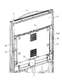
- FIG. 2 is a perspective view of a main part viewed from the back side of the outer door of FIG.
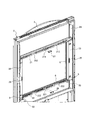
- FIG. 3 is an exploded perspective view in which the display device is disassembled from the outer door of FIG. 2.
- 4 is a rear perspective view showing a window portion of the outer door of FIG.
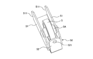
- FIG. 5 is a perspective view of the roller of FIG.
- FIG. 6 is an enlarged view of a main part showing a support state of the display device by the roller of FIG.
- FIG. 7 is a rear perspective view of the outer door showing a state in which the display device is inverted.
- FIG. 1 is a perspective view showing the overall configuration of a vending machine according to Embodiment 1 of the present invention.
- reference numeral 1 denotes a product such as a canned beverage or a plastic bottled beverage in a cold state or a hot state.
- a vending machine main body which is a heat-insulating housing that is stored separately, 2 is a single-opening type outer door supported by a hinge on the front surface of the vending machine main body 1 by a hinge, and 3 is a mode that covers the front surface of the outer door 2 It is the decoration panel arrange
- the decorative panel 3 is made of plastic and is attached to the outer door 2 via upper, lower, left and right decorative frames 31 to 34 provided at the periphery, and the vending machine is rounded by curving the upper and lower edges. This differentiates it from a vending machine with an angular appearance.
- the decorative panel 3 is formed with an opening so that parts provided on the front surface of the outer door 2 in the region covered with the decorative panel 3 are exposed on the surface. I will omit the explanation.
- a large opening window 20 is provided in the upper area of the front surface of the outer door 2, and a display device 4 for displaying images of products to be sold is rotatably mounted on the window 20.
- a coin insertion slot 2a a bill insertion slot 2b, a coin return slot 2c, a return lever 2d, a product outlet 2e, an electronic money reader / writer antenna 2f, a magnetic recording card reader / writer are provided on the front surface of the outer door 2.
- a human body sensing sensor such as a proximity sensor for sensing a human body
- a camera unit 2h such as a CCD camera for photographing a purchaser, a handle lock or a cylinder lock 2j, and the like are provided.
- a coin mechanism that stores coins in a denomination change tube or a safe and dispenses coins from the denomination change tube based on a change payout command, and the denomination and trueness of a bill inserted in communication with the bill insertion slot 2b.
- a bill validator that temporarily holds a banknote after determining it as false and returns the banknote temporarily held when it is determined as a false coin to the banknote insertion slot 2b, while taking the banknote temporarily held when it is determined as a true coin into a safe.
- a vending machine control unit that controls the entire vending machine, a control box that incorporates a display control unit that controls the display of the display device 4, and the like are provided.
- the display device 4 that is rotatably mounted on the window 20 of the outer door 2 includes, for example, a liquid crystal display, and the liquid crystal panel 4a serving as a display surface faces the window 20 of the outer door 2 in a manner facing the front side of the outer door 2. It is installed.
- the display device 4 includes a thin box-shaped casing 41 and a cover 42 that closes the opening of the casing 41. 40, the front surface of the housing 41 is opened, and a plurality of ventilation slits are formed in the flange forming the periphery.
- an aluminum frame chassis that supports the liquid crystal panel 4a from behind, and a circuit board that drives and controls the light emission of the liquid crystal panel 4a.
- the upper and lower flanges of the housing 41 are provided with rotating shafts 43 and 44 extending in the vertical direction.
- an iron magnetic attracting piece 45 is fixed to a substantially central portion in the vertical direction of the flange on the left side of the housing 41 when viewed from the front.
- the magnetic attracting piece 45 is formed in an L-shaped cross section, and the long L-shaped piece is formed such that the L-shaped short piece is flush with the back surface of the cover 42 and protrudes outward (left side). It is fixed to the left flange of the casing 41.
- This magnetic attracting piece 45 constitutes a magnetic attracting part of the display device 4.
- the cover 42 is formed with a plurality of ventilation slits and four rubber protrusions 46 protruding toward the back side.
- the protrusion height of the rubber protrusion 46 is the same as the distance between the cover 42 and the heat insulating door (not shown) disposed behind the cover 42, and the rubber protrusion 46 is formed on the heat insulating door.
- the rotating shaft 44 provided on the lower side prevents the lower part of the display device 4 (the lower flange of the casing 41) from coming into contact (sliding contact) with the peripheral edge of the window 20. Therefore, it is formed in the form of a stepped screw.
- the window 20 of the outer door 2 is formed to a size that can accommodate the display device 4, and frames 21 to 24 (see FIGS. 3 and 4) are provided along the periphery of the window 20.
- These frames 21 to 24 are formed as upper, lower, left, and right window frames of the window 20.
- the frame 21 that forms the upper window frame of the window 20 is the upper frame
- the frame 22 that forms the lower window frame of the window 20 is the lower frame
- the frame 23 forming the left window frame of the window 20 is called the left frame
- the frame 24 forming the right window frame of the window 20 is called the right frame.
- the upper frame 21 and the lower frame 22, the left frame 23 and the right frame 24 are made of the same member, and the other (the lower frame 22, the right frame 24) is the other (the upper frame 21, the left frame 23). It is configured to rotate and install.
- the upper frame 21 is made of metal having a U-shaped cross section, and the left and right ends are screwed to the door frame 2 ⁇ / b> A of the door 2 with the U-shaped open surface facing upward.
- the outer door 2 is integrally fixed.
- a bearing recess 211 that opens toward the back side is formed in the central portion of the upper frame 21 in the left-right direction.
- the lower frame 22 is one that is fixed to the door frame 2A of the outer door 2 after the upper frame 21 is rotated 180 degrees in the left-right direction in FIG. 4, and a bearing recess 221 that can be understood with reference to the lower frame 22.
- the (bearing recess 211) is formed in a funnel shape, and the portion that opens like a morning glory flower faces the back side, and the narrow and sharp portions serve as bearings for the rotating shafts 43 and 44 of the display device 4. Yes.
- the rotating shaft 44 on the lower side of the display device 4 is formed in the form of a stepped screw, and the diameter of the thin shaft portion on the tip end side forms a bearing recess 221 (bearing recess 211).
- the diameter of the thick shaft portion on the base side is smaller than the size of the narrow-pointed portion, and larger than the size of the funnel-shaped narrow-pointed portion constituting the bearing recess 221 (bearing recess 211). It is.
- Closure members 27 and 28 are attached to the bearing recesses 211 and 221, respectively.
- the closing members 27 and 28 close the portions that open to the back side while leaving the narrow and sharp portions of the funnel-shaped bearing recesses 211 and 221.
- the lower frame 22 is fixed with screws.
- the upper frame 21 and the lower frame 22 are formed with notches 212 and 222 cut out from one U-shaped leg piece (back side) to the U-shaped base end portion within a range in which strength is ensured.
- the air permeability from 4 is ensured, and a plurality of ventilation slits are formed at locations other than the notches 212 and 222.
- the left frame 23 and the right frame 24 are formed in an L-shaped cross-section, and the upper and lower ends of the L-shaped long piece are aligned with the upper frame 21 and the lower frame in such a manner that the L-shaped short piece extends along the left and right edges of the window 20. Screwed to the frame 22 and fixed to the outer door 2 integrally.
- the right frame 24 is obtained by rotating the left frame 23 180 degrees in the left-right direction in FIG. 4 and then screwing the upper and lower ends thereof to the upper frame 21 and the lower frame 22 and fixing them to the outer door 2.
- Magnets 25 and 26 are embedded in substantially vertical center portions of the long L-shaped pieces screwed to the upper frame 21 and the lower frame 22 of the left frame 23 and the right frame 24.
- the magnets 25 and 26 are configured to be disposed on the left and right objects in a manner facing the magnetic attracting piece 45 of the display device 4.
- the magnets 25 and 26 constitute a magnetic attracting part of the window frame (the left and right frames 23 and 24) of the window 20.
- rollers 5 and 5 are attached to the left and right ends of the lower frame 22 via support members 50 and 50 in such a manner that a part of the outer periphery is exposed above the lower frame 22.
- the rollers 5 and 5 and the supporting members 50 and 50 are made of the same parts, and a perspective view thereof is shown in FIG.
- the roller 5 is pivotally supported by a rotating shaft 5 ⁇ / b> A, and the rotating shaft 5 ⁇ / b> A is held by both wing pieces 51, 51 of the support member 50.
- the support member 50 is a development piece having a shape of a wing plate and bending and raising a portion to be a handle to form a fixed piece 52, and bending both of the left and right wings of the wing plate to form both wing pieces 51 and 51.
- a screw insertion hole 521 is formed in each of the blades 51, 51, a holding hole (not shown) of the rotating shaft 5 A is formed, and locking claws 511, 511 are formed at the end opposite to the fixed piece 52. Yes.
- the height of both blade pieces 51, 51 is determined to be a height at which a part of the outer periphery of the roller 5 assembled to both blade pieces 51, 51 via the rotating shaft 5A protrudes upward.
- An opening 223 (see FIG. 6) through which a part of the outer periphery of the roller 5 is inserted is formed at the base end portion of the lower frame 22.
- the support member 50 to which the roller 5 is assembled is attached to the lower frame 22 as follows. That is, the locking claws 511 and 511 of the both wing pieces 51 and 51 of the support member 50 are formed on flanges (not shown) bent from the tip of the other leg piece (front side) of the U-shaped lower frame 22 to the back side. With the roller 5 facing the opening 223 formed at the base end of the lower frame 22 after the locking, the fixing piece 52 is inserted into one leg (back side) of the U-shaped lower frame 22 with a screw insertion hole 521. It is fixed with screws.
- the roller 5 is disposed on the lower frame 22 in such a manner that a part of the outer periphery protrudes upward from the lower frame 22 and the rotating shaft 5A extends in the left-right direction of the outer door 2.
- 6 is a gasket that is integrally attached to the upper, lower, left and right frames 21 to 24 so as to protrude into the window 20, and in FIG. The arranged gasket 6 is visible.
- 2 and 3 7 is a wiring cover that covers the wiring of the display device 4, and 8 is a cover that protects an illumination lamp light source (not shown) disposed in the upper region of the outer door 2.
- the window frames (the upper and lower frames 21 and 22 and the left and right frames 23 and 24) along the periphery of the window 20 of the outer door 2
- preparation for mounting the display device 4 on the window 20 is completed.
- the liquid crystal panel 4 a that serves as a display surface from the back side of the outer door 2 is provided. It mounts
- the display device 4 is penetrated through the window 20 through the other end portion (right side in front view) opposite to the one end portion (left side in front view) to which the magnetic attracting piece 45 of the display device 4 is fixed. 4 are inserted into the bearing recesses 211 and 221 of the upper and lower frames 21 and 22.
- the display device 4 when the upper and lower rotary shafts 43 and 44 of the display device 4 are inserted into the bearing recesses 211 and 221 of the upper and lower frames 21 and 22, the display device 4 is mounted in an inclined state intersecting the window 20. As compared with the case where the display device 4 (liquid crystal panel 4a) is mounted in a state parallel to the surface of the window 20, the display device 4 can be easily held by hand.
- the rotating shaft 44 on the lower side of the display device 4 is formed in the form of a stepped screw, and the large-diameter shaft portion is configured to contact the surface of the lower frame 22.
- the (lower flange of the casing 41) is lifted without coming into contact with the lower edges of the lower frame 22 and the window 20, and the display device 4 can be easily rotated.
- the magnetic attracting piece 45 provided at one end of the display device 4 is left.
- the display device 4 is locked (locked) to a normal position by being attracted by a magnet 25 provided on the frame 23.
- the lower portion of the display device 4 (the lower flange of the housing 41) is the lower frame 22. Since it rides on the rollers 5 and 5 arranged at the left and right ends, the load on the rotating shaft 44 can be reduced.
- the outer door 2 is opened.
- the back side of the outer door 2 is exposed (see FIG. 2), so that the magnetic attracting piece 45 of the display device 4 and the magnet 25 provided on the left frame 23 are unlocked to the normal position. After that, the display device 4 is reversed.
- the other end portion on the opposite side to the one end portion (the left end side in the front view) to which the magnetic attracting piece 45 of the display device 4 is fixed is the other end portion (the right end side in the front view).
- the left end portion is pressed forward with a force that overcomes the attractive force of the magnet 25 (see FIG. 3) provided on the left frame 23, the magnetic attracting piece 45 of the display device 4 is separated from the magnet 25.
- the device 4 is rotated around the rotation shafts 43 and 44.
- the magnetic attracting piece 45 of the display device 4 is attracted to the magnet 26 (see FIG. 3) provided on the right frame 24 and displayed on the display device 4.
- the surface (liquid crystal panel 4 a) is locked (locked) at a reversal position facing the back side of the outer door 2.
- the display device 4 when the display device 4 is inverted so that the display surface (liquid crystal panel 4 a) faces the back side of the outer door 2, the display device 4 is locked (locked) by the magnetic attracting piece 45 and the magnet 26. Therefore, the display device 4 is prevented from rotating unexpectedly from the reverse position.
- a procedure reverse to the procedure for inverting the display device 4 may be performed.
- the outer door 2 disposed on the front surface of the vending machine body 1 so as to be freely opened and closed, and the rectangular opening greatly opened on the customer service surface of the outer door 2.
- a vending machine that is mounted on a window 20 having a shape and displays at least an image of a product to be sold and has a rectangular display device 4 having a touch panel type switch function, an upper and lower portions of the display device 4 Rotating shafts 43 and 44 are provided that extend in the vertical direction and are positioned substantially on the center of gravity line of the display device 4, and are separated from the rotating shafts 43 and 44 of the display device 4.
- Magnetic attracting portions (magnetic attracting pieces 45, magnets 25, 26) that attract each other magnetically are provided at portions facing the window frames (left and right frames 23, 24), respectively. 3 and 44 are pivotally supported on the window frame of the window 20, and the display device 4 is supported by the magnetic adsorption portions (magnetic adsorption pieces 45, magnets 25 and 26) provided on the display device 4 and the window frames (left and right frames 23 and 24).
- the magnetic attracting portions provided on the display device 4 and the window frames (the left and right frames 23 and 24) in the normal state by being respectively locked at the normal position or the reverse position reversed to the front side or the back side of the outer door 2.
- the display device 4 can be locked (locked) to the normal position facing the front side of the outer door 2 by the (magnetic attracting piece 45, magnet 25, 26), while the outer door 2 is opened and the display device 4 is inverted.
- the worker simply displays the display device 4 by applying a rotational force that overcomes the attractive force of the magnetic attracting portions (the magnetic attracting piece 45 and the magnet 25) provided on the display device 4 and the window frame (left frame 23).
- apparatus Can be reversed, and the inverted display device 4 is locked (locked) at the reverse position facing the back side by the respective magnetic attracting portions (magnetic attracting pieces 45, magnets 26), so that it rotates unexpectedly. This can be prevented.
- the magnetic attracting piece 45 includes the magnetic attracting piece 45 provided on the display device 4 and the magnets 25 and 26 provided on the left and right frames 23 and 24, and the magnetic attracting piece 45 is located outside the display device 4. While the display device 4 has been described as projecting to the left (left side), the display device 4 is locked (locked) at the normal position, that is, the space enclosed by the upper, lower, left, and right frames 21 to 24 is accommodated. Thus, it is possible to provide magnetic attracting portions on the facing surfaces of the display device 4 and the upper, lower, left and right frames 21 to 24, respectively.
- the display device 4 displays images of products to be sold and has a touch panel type switch function, in addition to providing a communication means for wirelessly connecting to a network, so that the display device 4 can be used as an electronic signboard, or can provide maintenance information from a distance. It is possible to support the provision and maintenance method. Therefore, the present invention is not limited to the embodiment.
Landscapes
- Physics & Mathematics (AREA)
- General Physics & Mathematics (AREA)
- Control Of Vending Devices And Auxiliary Devices For Vending Devices (AREA)
Abstract
外扉(2)に開口した窓に表示装置(4)を回転可能に軸支するとともに表示装置(4)と窓(20)の窓枠を形成する左フレーム(23),(24)とのそれぞれ対峙する部位に互いに磁気により吸引し合う磁気吸着片(45)、磁石(25),(26)を設け、前記表示装置(4)が外扉(2)の正面側を向く通常位置では磁気吸着片(45)を磁石(25)に吸着させて係止する一方、表示装置(4)が外扉(2)の背面側を向くように反転した反転位置では磁気吸着片(45)を磁石(26)に吸着させて係止することにより、表示装置(4)を反転させた際にも表示装置(4)の不測の回転を防止する。
Description
この発明は、自動販売機本体の前面を開閉する外扉の接客面に販売する商品の画像などを表示する表示装置を備えた自動販売機に関し、特に表示装置の表示面を外扉の正面側および背面側に向けて回転可能とした自動販売機に関するものである。
例えば、缶入り飲料やペットボトル入り飲料などの商品(清涼飲料等の商品)を販売する自動販売機は、一般的に、断熱筐体としてなる自動販売機本体の商品収納庫内に前記商品をコールド状態、ホット状態に区分して保存するとともに外扉の接客面の上部領域に大きく開口した窓を透明板で閉塞してなるディスプレイ室内に複数の商品見本を左右に並べて展示し、前記商品見本に対応して設けられた商品選択ボタンの操作に基いて選択された商品を販売するように構成されている。
この自動販売機においては、商品見本が商品を模したプラスチック製になり、商品の入れ替えに伴う商品見本の交換、或いは展示位置の変更の際、外扉を開放してディスプレイ室に展示された商品見本の交換や着脱を行わねばならないので手間がかかるものであった。
このため、販売する商品の画像を表示する液晶ディスプレイを外扉の接客面に配設し、必要に応じて商品の種類や表示位置を設定、変更するようにしたものが出現している。液晶ディスプレイの薄型化や大型化は著しく、従前のプラスチック製の商品見本を展示するディスプレイ室の大きさに相当する液晶ディスプレイを採用し、外扉の接客面に大きく開口した窓に配設する一方、液晶ディスプレイの表示面にタッチした位置の座標から選択された商品を検出するタッチパネル式のスイッチ機能によって液晶ディスプレイの表示面にタッチすることにより商品の選択を行うとともに選択された商品を大きく拡大して表示したり、点滅させたりするものも知られている(例えば、特許文献1参照)。
ところで、外扉の接客面に配設される液晶ディスプレイは外扉に固定して取付けられるのが一般的である一方、液晶ディスプレイを回転可能に配設し、液晶ディスプレイの表示面を外扉の正面側および背面側に向けて反転可能とした自動販売機も知られている(例えば、特許文献2参照)。この特許文献2に開示された発明によれば、外扉を開放して自動販売機の各種設定、メンテナンスを行う際に液晶ディスプレイを反転させてモニターとして活用できることが可能になる点で優れている。
ところで、前記特許文献2に開示された発明にあっては、液晶ディスプレイを回転可能に配設するため、液晶ディスプレイの左右一端側に上下方向に延在する回転軸を設けてヒンジ式に支持する一方、通常時(販売時)に液晶ディスプレイの回転を阻止するために回転軸とは反対側にロック機構が設けられ、液晶ディスプレイを回転(反転)させる際には作業員がロック機構を外すように構成されている。このため、液晶ディスプレイを回転(反転)させる際に作業員がロック機構を解除せねばならず手間がかかるものである。
また、液晶ディスプレイを表示面が背面側に向くように反転させた状態では液晶ディスプレイが自由に動き得るフリーな状態にあるので、液晶ディスプレイが不測に回転して表示面が見辛くなるおそれがあるという課題を有する。
特に、特許文献1に開示された発明のように大型の液晶ディスプレイの場合には液晶ディスプレイの不測の回転により作業員の思わぬ怪我、或いは液晶ディスプレイの表示面に物が衝突、若しくは液晶ディスプレイの回転を阻止しようとして液晶ディスプレイの表示面に強い衝撃を与えた際には液晶ディスプレイの表示面が破損するおそれがある。
本発明は上記の点に鑑みてなされたものであり、その目的は前記課題を解決し、外扉の接客面に設けられた窓に装着される表示装置の表示面を外扉の正面側および背面側に向けて反転するように回転可能に配置するとともに当該表示装置をその表示面が外扉の正面側若しくは背面側を向く通常位置および反転位置にそれぞれ係止することが可能な自動販売機を提供することにある。
上記目的を達成するために、本発明に係る自動販売機は、自動販売機本体の前面に開閉自在に配設された外扉と、前記外扉の接客面に設けられた矩形状の窓に装着され、少なくとも販売する商品の画像を表示するとともにタッチパネル式のスイッチ機能を有する矩形状の表示装置とを備えてなる自動販売機において、前記表示装置の上部および下部にそれぞれ上下方向に延在するとともに表示装置の略重心線上に位置する回転軸が設けられ、前記表示装置の回転軸から離隔した部位であって表示装置と窓の窓枠とのそれぞれ対峙する部位に互いに磁気により吸引し合う磁気吸着部が設けられ、前記表示装置の回転軸を窓の窓枠に軸支するとともに前記表示装置および窓枠に設けられた磁気吸着部により表示装置が外扉の正面側若しくは背面側に反転した通常位置若しくは反転位置にそれぞれ係止されることを特徴とする。
また本発明は、上記自動販売機において、前記窓の窓枠のうちの下方の窓枠における左右両端にその一部が露出する態様で軸線が外扉の左右方向に延在するローラーを有することを特徴とする。
また本発明は、上記自動販売機において、前記磁気吸着部は、一方が磁石であり、他方が鉄製の磁気吸着片からなることを特徴とする。
また本発明は、上記自動販売機において、前記磁気吸着片は表示装置の左右端部のいずれか一方の端部に該表示装置から側方に突出して配設され、磁石は窓の左右窓枠における前記磁気吸着片と対峙する部位に配設されてなることを特徴とする。
本発明に係る自動販売機によれば、自動販売機本体の前面に開閉自在に配設された外扉と、前記外扉の接客面に設けられた矩形状の窓に装着され、少なくとも販売する商品の画像を表示するとともにタッチパネル式のスイッチ機能を有する矩形状の表示装置とを備えてなる自動販売機において、前記表示装置の上部および下部にそれぞれ上下方向に延在するとともに表示装置の略重心線上に位置する回転軸が設けられ、前記表示装置の回転軸から離隔した部位であって表示装置と窓の窓枠とのそれぞれ対峙する部位に互いに磁気により吸引し合う磁気吸着部が設けられ、前記表示装置の回転軸を窓の窓枠に軸支するとともに前記表示装置および窓枠に設けた磁気吸着部により表示装置が外扉の正面側若しくは背面側に反転した通常位置若しくは反転位置にそれぞれ係止されることにより、通常時においては表示装置および窓枠に設けたそれぞれの磁気吸着部によって表示装置が外扉の正面側を向く通常位置にロック(係止)することができる一方、外扉を開放して表示装置を反転させる際、作業員は表示装置および窓枠に設けたそれぞれの磁気吸着部の吸引力に打ち勝つ回転力を表示装置に加えるのみで表示装置を反転させることができ、かつ、反転した表示装置はそれぞれの磁気吸着部によって背面側を向いた反転位置にロック(係止)されるので不測に回転することを防止できるという効果を奏する。
以下、本発明の実施の形態にかかる自動販売機を図面に基づいて詳細に説明する。
図1は、本発明の実施の形態1にかかる自動販売機の全体構成を示す斜視図であり、図1において、1は缶入り飲料やペットボトル入り飲料などの商品をコールド状態、ホット状態に区分して保存する断熱筐体としてなる自動販売機本体、2は自動販売機本体1の前面にヒンジにより開閉可能に支持された片開き式の外扉、3は外扉2の前面を覆う態様で配設された装飾パネルである。
前記装飾パネル3はプラスチック製になり、周縁に設けられた上下左右の化粧枠31~34を介して外扉2に取付けられ、上下縁部を湾曲させることにより自動販売機を丸みを帯びた外観とすることにより角ばった外観の自動販売機と差別化するものである。
なお、装飾パネル3には、当該装飾パネル3に覆われた領域の外扉2の前面に設けられる部品が表面に露出するように開口が形成されているものであるが、以下ではその開口の説明(記載)は割愛する。
前記外扉2の前面の上部域には大きく開口した窓20が設けられ、この窓20に販売する商品の画像などを表示する表示装置4が回転可能に装着されている。
また、外扉2の前面には硬貨投入口2a、紙幣挿入口2b、硬貨返却口2c、返却レバー2d、商品取出口2e、電子マネーリーダライタのアンテナ部2f、磁気記録式のカードのリーダライタ2g、人体を感知する近接センサなどの人体感知センサと購入者を撮影するCCDカメラなどのカメラユニット2h、ハンドルロックまたはシリンダー錠2jなどが設けられている。
なお、外扉2の背面に硬貨投入口2aに連通して投入硬貨の金種および真偽を判定して偽貨として判定された硬貨を硬貨返却口2cに返却する一方、正貨として判定された硬貨を金種別の釣銭筒若しくは金庫に収納し、釣銭払出指令に基づいて金種別の釣銭筒から硬貨を払い出すコインメカニズム、紙幣挿入口2bに連通して挿入された紙幣の金種および真偽を判定したうえで一時保留し、偽貨として判定された際に一時保留した紙幣を紙幣挿入口2bに返却する一方、正貨として判定された際に一時保留した紙幣を金庫に取り込むビルバリデータ、自動販売機全体の制御を司る自動販売機制御部、表示装置4の表示を制御する表示制御部を内蔵する制御ボックスなどが配設されているのは周知のとおりである。
外扉2の窓20に回転可能に装着される表示装置4は、例えば、液晶ディスプレイからなり、表示面となる液晶パネル4aが外扉2の正面側を向く態様で外扉2の窓20に装着されている。
この表示装置4は、外扉2の窓20から取り外した状態の分解斜視図である図3に示すように、薄い箱型の筺体41と筺体41の開口部を閉塞するカバー42とからなるケース40を備え、筺体41の前面は開口されるとともに周縁を形成するフランジには複数の通気用スリットが形成されている。
ケース40の内部には、液晶パネル4aを背後から支持するアルミニウム製のフレームシャーシ、液晶パネル4aの発光駆動とその制御を行う回路基板が内蔵されている。筺体41の上下フランジには上下方向に延在する回転軸43,44が設けられている。
これらの回転軸43,44は、表示装置4の重心線上に位置している。また、筺体41の正面視左側のフランジの上下方向の略中央部には鉄製の磁気吸着片45が固着されている。この磁気吸着片45は横断面L字状に形成され、L字状の短い片がカバー42の背面と面一であって外方(左側方)に突出する態様でL字状の長い片を筺体41の左側フランジに固着して設けられている。この磁気吸着片45が表示装置4の磁気吸着部を構成する。
そして、カバー42には複数の通気用スリットが形成されるとともに背面側に向けて突出するゴム製の突起46が4個設けられている。このゴム製の突起46の突起高さは、カバー42と、その後方に配設されている断熱扉(不図示)の離間距離と同じ高さで形成され、ゴム製の突起46が断熱扉に当接することにより、外扉2の閉時に通常位置の状態である表示装置4の不測の回転を防止する。
なお、回転軸43,44のうち、下方側に設けられた回転軸44は表示装置4の下部(筐体41の下フランジ)が窓20の周縁に当接(摺接)するのを防止するために段付きねじの形態に形成されている。
外扉2の窓20は前記表示装置4を収容可能な大きさに形成され、窓20の周縁に沿ってフレーム21~24(図3および図4参照)が設けられている。
これらフレーム21~24は、窓20の上下左右の窓枠として形成され、以下では窓20の上側の窓枠を形成するフレーム21を上フレーム、窓20の下側の窓枠を形成するフレーム22を下フレーム、窓20の正面視左側の窓枠を形成するフレーム23を左フレーム、窓20の正面視右側の窓枠を形成するフレーム24を右フレームと称することとする。
なお、上フレーム21と下フレーム22、左フレーム23と右フレーム24とはそれぞれ同一の部材からなり、一方(上フレーム21、左フレーム23)に対し、他方(下フレーム22、右フレーム24)を回転させて取付けるように構成されている。
図4に示すように上フレーム21は横断面コ字状に形成された金属製になり、コ字状の開放面が上方を向く態様で左右両端を扉2の扉枠2Aにねじ止めされて外扉2に一体的に固着されている。
上フレーム21の左右方向の中央部には背面側に向けて開放した軸受凹所211が形成されている。下フレーム22は、上フレーム21を図4において左右方向に180度回転させたうえで外扉2の扉枠2Aに固着したものであり、下フレーム22を参照すると理解できるように軸受凹所221(軸受凹所211)は漏斗状に形成されて朝顔の花のように開く部分が背面側を向き、細くとがった部分が表示装置4の回転軸43,44の軸受となるように構成されている。
ここで、表示装置4の下方側の回転軸44は段付きねじの形態に形成されており、その先端側の細い軸部の径が軸受凹所221(軸受凹所211)を構成する漏斗状の細くとがった部分の寸法よりも小さく、基部側の太い軸部の径が軸受凹所221(軸受凹所211)を構成する漏斗状の細くとがった部分の寸法よりも大きく定められているものである。
前記軸受凹所211,221には、それぞれ閉塞部材27,28が取付けられる。この閉塞部材27,28は、漏斗状の軸受凹所211,221の細くとがった部分を残して背面側に開く部分を閉鎖するものであり、横断面コ字状に形成されて上フレーム21,下フレーム22にねじ止めして固着される。
なお、上フレーム21,下フレーム22は強度が保障される範囲でコ字状の一方(背面側)の脚片からコ字状基端部まで切り欠いた切欠212,222を形成して表示装置4からの通気性を確保し、切欠212,222以外の箇所には複数の通気用スリットを形成している。
左フレーム23、右フレーム24は横断面L字状に形成され、L字状の短い片を窓20の左右の縁に沿わせる態様でL字状の長い片の上下両端を上フレーム21と下フレーム22にねじ止めしてそれぞれ外扉2に一体的に固着されている。
この場合、右フレーム24は、左フレーム23を図4において左右方向に180度回転させたうえでその上下両端を上フレーム21と下フレーム22にねじ止めして外扉2に固着したものである。そして、左フレーム23、右フレーム24の上フレーム21と下フレーム22にねじ止めされたL字状の長い片における上下方向の略中央部には磁石25,26が埋設されている。
この磁石25,26は表示装置4の磁気吸着片45に対峙する態様で左右対象に配設されるように構成されている。この磁石25,26が窓20の窓枠(左右フレーム23,24)の磁気吸着部を構成する。
また、下フレーム22の左右両端にはローラー5,5が、その外周の一部が下フレーム22の上方に露出する態様で、支持部材50,50を介して取付けられている。このローラー5,5および支持部材50,50は同一の部品からなり、その斜視図を図5に示す。
図5に示すように、ローラー5は回転軸5Aに回動自在に軸支され、回転軸5Aが支持部材50の両翼片51,51に保持されてなるものである。支持部材50は、展開図が羽子板状をなして持ち手となる部位を曲げ起こして固定片52とし、羽子板状の左右両翼を曲げ起こして両翼片51,51としたものであり、固定片52にねじ挿通孔521が形成され、両翼片51,51に回転軸5Aの保持孔(不図示)が形成されるとともに固定片52と反対側の端部に係止爪511,511が形成されている。
なお、両翼片51,51の高さは、両翼片51,51に回転軸5Aを介して組み付けられたローラー5の外周の一部が上方に突出する高さに定められ、また、コ字状の下フレーム22の基端部にはローラー5の外周の一部を挿通する開口223(図6参照)が形成されているものである。
ローラー5が組付けられた支持部材50は次のようにして下フレーム22に取付けられる。すなわち、支持部材50の両翼片51,51の係止爪511,511をコ字状の下フレーム22の他方(正面側)の脚片の先端から背面側に折り曲げられたフランジ(不図示)に係止したうえでローラー5を下フレーム22の基端部に形成した開口223に臨ませつつ固定片52をコ字状の下フレーム22の一方(背面側)の脚片にねじ挿通孔521を介してねじ止めして固着する。
これにより、ローラー5が、その外周の一部が下フレーム22から上方に突出するとともに回転軸5Aが外扉2の左右方向に延在する態様で下フレーム22に配設される。
なお、図4において、6は上下左右フレーム21~24に一体的に取付けられて窓20内に向けて突出するように配設されたガスケットであり、図4では下フレーム22、左フレーム23に配設されたガスケット6が見えている。また、図2および図3において、7は表示装置4の配線を覆う配線カバー、8は外扉2の上部領域に配設される照明灯光源(不図示)を保護するカバーである。
前述したように、外扉2の窓20の周縁に沿って窓枠(上下フレーム21,22および左右フレーム23,24)を取付けることにより窓20に表示装置4を装着する準備が完了する。この状態から上下フレーム21,22の軸受凹所211,221に対峙して取付けられる閉塞部材27,28を取り外したうえで表示装置4を外扉2の背面側から表示面となる液晶パネル4aが外扉2の正面側を向く態様で外扉2の窓20に次のように装着する。
すなわち、表示装置4の磁気吸着片45が固着された一方側の端部(正面視左端側)とは反対側の他方側の端部(正面視右端側)を窓20を貫通させつつ表示装置4の回転軸43,44を上下フレーム21,22の軸受凹所211,221に挿入させる。
このように、表示装置4の上下の回転軸43,44を上下フレーム21,22の軸受凹所211,221に挿入させるに当たり、表示装置4を窓20と交差する態様に傾けた状態で装着すると、表示装置4(液晶パネル4a)を窓20の面に平行な状態で装着する場合に比して表示装置4を手で保持することが容易となる。
前述したように、表示装置4の回転軸43,44を上下フレーム21,22の軸受凹所211,221に挿入させた後、軸受凹所211,221に対峙する閉塞部材27,28を上下フレーム21,22にねじ止めする。
これにより、表示装置4の回転軸43,44が軸受凹所211,221から脱落するのが防止される。ここで、表示装置4の下方側の回転軸44が段付きねじの形態に形成されて太径の軸部が下フレーム22の面に当接するように構成されているので、表示装置4の下部(筐体41の下フランジ)が下フレーム22および窓20の下縁に当接することなく浮き上がっており、表示装置4を容易に回転させることができる。
この後、窓20に対して傾いた状態にある表示装置4を窓20の面と面一となるように回転させると、表示装置4の一方側の端部に設けた磁気吸着片45が左フレーム23に設けた磁石25に吸着されて表示装置4を通常位置にロック(係止)する。
このように、窓20に装着された表示装置4が磁石25と磁気吸着片45とにより通常位置にロックされた状態では、表示装置4の下部(筐体41の下フランジ)が下フレーム22の左右両端に配設したローラー5,5に乗り上げているので、回転軸44に掛かる負荷を軽減することができる。
さて、表示装置4の表示面(液晶パネル4a)が外扉2の正面側を向く通常位置に保持された表示装置4を反転させる際には外扉2を開放させる。外扉2を開放すると外扉2の背面側が露出(図2参照)するので、表示装置4の磁気吸着片45と左フレーム23に設けた磁石25による表示装置4の通常位置へのロックを解除したうえで表示装置4を反転させる。
つまり、表示装置4の磁気吸着片45が固着された一方側の端部(正面視左端側)とは反対側の他方側の端部他方側の端部(正面視右端側であり、図2においては左方の端部)を、左フレーム23に設けた磁石25(図3参照)の吸引力に打ち勝つ力で前方に押圧すると表示装置4の磁気吸着片45が磁石25から離れるので、表示装置4を回転軸43,44を中心に回転させる。
そして、表示装置4が略180度回転した状態(図7参照)では、表示装置4の磁気吸着片45が右フレーム24に設けた磁石26(図3参照)に吸着して表示装置4の表示面(液晶パネル4a)が外扉2の背面側を向く反転位置にロック(係止)される。
このように、表示装置4を表示面(液晶パネル4a)が外扉2の背面側を向く状態に反転させた際、表示装置4は磁気吸着片45と磁石26によりロック(係止)されるので、表示装置4が反転位置から不測に回転するのが防止される。反転位置にロック(係止)された表示装置4を通常位置に戻すには、表示装置4を反転させる際の手順と逆の手順により行えばよい。
前述したように、この実施の形態にかかる自動販売機においては、自動販売機本体1の前面に開閉自在に配設された外扉2と、前記外扉2の接客面に大きく開口された矩形状の窓20に装着され、少なくとも販売する商品の画像を表示するとともにタッチパネル式のスイッチ機能を有する矩形状の表示装置4とを備えてなる自動販売機において、前記表示装置4の上部および下部にそれぞれ上下方向に延在するとともに表示装置4の略重心線上に位置する回転軸43,44を設け、前記表示装置4の回転軸43,44から離隔した部位であって表示装置4と窓20の窓枠(左右フレーム23,24)とのそれぞれ対峙する部位に互いに磁気により吸引し合う磁気吸着部(磁気吸着片45、磁石25,26)を設け、前記表示装置4の回転軸43,44を窓20の窓枠に軸支するとともに前記表示装置4および窓枠(左右フレーム23,24)に設けた磁気吸着部(磁気吸着片45、磁石25,26)により表示装置4が外扉2の正面側若しくは背面側に反転した通常位置若しくは反転位置にそれぞれ係止することにより、通常時においては表示装置4および窓枠(左右フレーム23,24)に設けたそれぞれの磁気吸着部(磁気吸着片45、磁石25,26)によって表示装置4が外扉2の正面側を向く通常位置にロック(係止)することができる一方、外扉2を開放して表示装置4を反転させる際、作業員は表示装置4および窓枠(左フレーム23)に設けたそれぞれの磁気吸着部(磁気吸着片45、磁石25)の吸引力に打ち勝つ回転力を表示装置4に加えるのみで表示装置4を反転させることができ、かつ、反転した表示装置4はそれぞれの磁気吸着部(磁気吸着片45、磁石26)によって背面側を向いた反転位置にロック(係止)されるので不測に回転することを防止できるものである。
なお、前述した実施の形態では、磁気吸着部として表示装置4に設けた磁気吸着片45と左右フレーム23,24に設けた磁石25,26からなり、磁気吸着片45が表示装置4の外方(左側方)に突出する態様のものについて説明したが、表示装置4が通常位置にロック(係止)された状態、つまり、上下左右のフレーム21~24で囲まれた空間の収容された状態で表示装置4と上下左右のフレーム21~24との対峙面にそれぞれ磁気吸着部を設けることもできるものである。
また、表示装置4は販売する商品の画像を表示するとともにタッチパネル式のスイッチ機能を有するものに加えて無線でネットワークと接続する通信手段を設けることにより電子看板として利用したり、遠方からメンテナンス情報の提供やメンテナンス方法の支持を行うようにすることができるものである。したがって、本発明は実施の形態に限定されるものではない。
1 自動販売機本体
2 外扉
4 表示装置
5 ローラー
20 窓
21 上フレーム
22 下フレーム
23 左フレーム
24 右フレーム
25 磁石
26 磁石
43 回転軸
44 回転軸
45 磁気吸着片
211 軸受凹所
221 軸受凹所
2 外扉
4 表示装置
5 ローラー
20 窓
21 上フレーム
22 下フレーム
23 左フレーム
24 右フレーム
25 磁石
26 磁石
43 回転軸
44 回転軸
45 磁気吸着片
211 軸受凹所
221 軸受凹所
Claims (4)
- 自動販売機本体の前面に開閉自在に配設された外扉と、
前記外扉の接客面に設けられた矩形状の窓に装着され、少なくとも販売する商品の画像を表示するとともにタッチパネル式のスイッチ機能を有する矩形状の表示装置と
を備えてなる自動販売機において、
前記表示装置の上部および下部にそれぞれ上下方向に延在するとともに表示装置の略重心線上に位置する回転軸が設けられ、前記表示装置の回転軸から離隔した部位であって表示装置と窓の窓枠とのそれぞれ対峙する部位に互いに磁気により吸引し合う磁気吸着部が設けられ、前記表示装置の回転軸を窓の窓枠に軸支するとともに前記表示装置および窓枠に設けられた磁気吸着部により表示装置が外扉の正面側若しくは背面側に反転した通常位置若しくは反転位置にそれぞれ係止されることを特徴とする自動販売機。 - 前記窓の窓枠のうちの下方の窓枠における左右両端にその一部が露出する態様で軸線が外扉の左右方向に延在するローラーを有することを特徴とする請求項1に記載の自動販売機。
- 前記磁気吸着部は、一方が磁石であり、他方が鉄製の磁気吸着片からなることを特徴とする請求項1に記載の自動販売機。
- 前記磁気吸着片は表示装置の左右端部のいずれか一方の端部に該表示装置から側方に突出して配設され、磁石は窓の左右窓枠における前記磁気吸着片と対峙する部位に配設されてなることを特徴とする請求項3に記載の自動販売機。
Priority Applications (2)
| Application Number | Priority Date | Filing Date | Title |
|---|---|---|---|
| CN201680019180.5A CN107533778B (zh) | 2015-06-25 | 2016-02-04 | 自动售货机 |
| JP2017524653A JP6439871B2 (ja) | 2015-06-25 | 2016-02-04 | 自動販売機 |
Applications Claiming Priority (2)
| Application Number | Priority Date | Filing Date | Title |
|---|---|---|---|
| JP2015-127449 | 2015-06-25 | ||
| JP2015127449 | 2015-06-25 |
Publications (1)
| Publication Number | Publication Date |
|---|---|
| WO2016208210A1 true WO2016208210A1 (ja) | 2016-12-29 |
Family
ID=57586277
Family Applications (1)
| Application Number | Title | Priority Date | Filing Date |
|---|---|---|---|
| PCT/JP2016/053328 Ceased WO2016208210A1 (ja) | 2015-06-25 | 2016-02-04 | 自動販売機 |
Country Status (3)
| Country | Link |
|---|---|
| JP (1) | JP6439871B2 (ja) |
| CN (1) | CN107533778B (ja) |
| WO (1) | WO2016208210A1 (ja) |
Families Citing this family (2)
| Publication number | Priority date | Publication date | Assignee | Title |
|---|---|---|---|---|
| CN109480547B (zh) * | 2019-01-09 | 2021-02-19 | 盈奇科技(深圳)有限公司 | 一种无人售货柜展示装置 |
| CN114283523A (zh) * | 2022-01-03 | 2022-04-05 | 江苏星星冷链科技有限公司 | 一种自动售货机的保温吸塑门体装置 |
Citations (4)
| Publication number | Priority date | Publication date | Assignee | Title |
|---|---|---|---|---|
| JPH0737124A (ja) * | 1993-07-20 | 1995-02-07 | Oki Electric Ind Co Ltd | 自動発券・販売機の筐体構造 |
| JPH08180252A (ja) * | 1994-12-26 | 1996-07-12 | Kubota Corp | 自動販売機の表示装置 |
| JPH10293546A (ja) * | 1997-04-22 | 1998-11-04 | Oki Electric Ind Co Ltd | 表示装置 |
| JP2002150384A (ja) * | 2000-11-13 | 2002-05-24 | Fuji Denki Reiki Co Ltd | 表示器付き自動販売機 |
Family Cites Families (10)
| Publication number | Priority date | Publication date | Assignee | Title |
|---|---|---|---|---|
| JP2985478B2 (ja) * | 1992-03-03 | 1999-11-29 | 富士電機株式会社 | 自動販売機のディスプレイ装置 |
| FR2717291B1 (fr) * | 1994-03-14 | 1996-07-05 | Hatem Triki | Caisson lumineux. |
| JP3541578B2 (ja) * | 1996-08-30 | 2004-07-14 | 神鋼電機株式会社 | 自動券売機 |
| JPH10232969A (ja) * | 1997-02-20 | 1998-09-02 | Fuji Electric Co Ltd | 自動販売機のディスプレイ装置 |
| JPH1158894A (ja) * | 1997-08-22 | 1999-03-02 | Nisca Corp | 情報記録装置および情報記録装置を備えた記録媒体発行機 |
| AU2000249590A1 (en) * | 1999-05-17 | 2000-12-05 | Ceemee Signs International Limited | Rotatable sign |
| JP2001312212A (ja) * | 2000-04-27 | 2001-11-09 | Nippon Signal Co Ltd:The | 液晶ディスプレイの角度調整機構 |
| JP5621247B2 (ja) * | 2009-11-30 | 2014-11-12 | 富士電機株式会社 | 自動販売機 |
| US8820575B2 (en) * | 2011-06-13 | 2014-09-02 | Convergent Media Systems Corporation | Digital signage retrofit for vending machine |
| CN104484949B (zh) * | 2014-12-19 | 2018-04-27 | 邓军 | 一种集现榨橙汁、灌流、装瓶及传媒为一体的自动售货机 |
-
2016
- 2016-02-04 CN CN201680019180.5A patent/CN107533778B/zh active Active
- 2016-02-04 JP JP2017524653A patent/JP6439871B2/ja active Active
- 2016-02-04 WO PCT/JP2016/053328 patent/WO2016208210A1/ja not_active Ceased
Patent Citations (4)
| Publication number | Priority date | Publication date | Assignee | Title |
|---|---|---|---|---|
| JPH0737124A (ja) * | 1993-07-20 | 1995-02-07 | Oki Electric Ind Co Ltd | 自動発券・販売機の筐体構造 |
| JPH08180252A (ja) * | 1994-12-26 | 1996-07-12 | Kubota Corp | 自動販売機の表示装置 |
| JPH10293546A (ja) * | 1997-04-22 | 1998-11-04 | Oki Electric Ind Co Ltd | 表示装置 |
| JP2002150384A (ja) * | 2000-11-13 | 2002-05-24 | Fuji Denki Reiki Co Ltd | 表示器付き自動販売機 |
Also Published As
| Publication number | Publication date |
|---|---|
| JPWO2016208210A1 (ja) | 2017-12-07 |
| CN107533778B (zh) | 2020-09-18 |
| JP6439871B2 (ja) | 2018-12-19 |
| CN107533778A (zh) | 2018-01-02 |
Similar Documents
| Publication | Publication Date | Title |
|---|---|---|
| EP2012282A2 (en) | Gaming machine | |
| AU2008202585B2 (en) | Gaming machine | |
| JP2005131156A (ja) | 遊技機 | |
| JP6439871B2 (ja) | 自動販売機 | |
| US20120118907A1 (en) | Vending machine-integrated table | |
| EP1415689B1 (en) | Gaming machine with hinge construction for a rotatably supporting door | |
| JPH11169536A (ja) | 遊技機 | |
| AU2005297073A1 (en) | Keypad security device | |
| JP4854592B2 (ja) | 制御基板ユニット及び遊技機 | |
| JP4570575B2 (ja) | 遊技機 | |
| US6964491B2 (en) | Gaming machine | |
| JP6508714B2 (ja) | 遊技機 | |
| JP2004024454A (ja) | 分離型スロットマシン | |
| JP4531727B2 (ja) | 遊技機 | |
| JP4924512B2 (ja) | 自動販売機 | |
| JP4335165B2 (ja) | 遊技機 | |
| JP4849559B2 (ja) | 遊技機の施錠装置 | |
| JP5786380B2 (ja) | 自動販売機 | |
| JP2018136622A (ja) | 会計装置 | |
| JP6508713B2 (ja) | 遊技機 | |
| JP6368191B2 (ja) | 遊技機 | |
| JP4889234B2 (ja) | パチンコ遊技機 | |
| JP4924537B2 (ja) | 自動販売機 | |
| JP2008197789A (ja) | 自動販売機 | |
| JP2008310494A (ja) | 自動販売機 |
Legal Events
| Date | Code | Title | Description |
|---|---|---|---|
| 121 | Ep: the epo has been informed by wipo that ep was designated in this application |
Ref document number: 16813981 Country of ref document: EP Kind code of ref document: A1 |
|
| ENP | Entry into the national phase |
Ref document number: 2017524653 Country of ref document: JP Kind code of ref document: A |
|
| NENP | Non-entry into the national phase |
Ref country code: DE |
|
| 122 | Ep: pct application non-entry in european phase |
Ref document number: 16813981 Country of ref document: EP Kind code of ref document: A1 |