WO2016203903A1 - 車両用空調装置 - Google Patents
車両用空調装置 Download PDFInfo
- Publication number
- WO2016203903A1 WO2016203903A1 PCT/JP2016/065150 JP2016065150W WO2016203903A1 WO 2016203903 A1 WO2016203903 A1 WO 2016203903A1 JP 2016065150 W JP2016065150 W JP 2016065150W WO 2016203903 A1 WO2016203903 A1 WO 2016203903A1
- Authority
- WO
- WIPO (PCT)
- Prior art keywords
- air
- heating
- refrigerant
- temperature
- condenser
- Prior art date
- Legal status (The legal status is an assumption and is not a legal conclusion. Google has not performed a legal analysis and makes no representation as to the accuracy of the status listed.)
- Ceased
Links
Images












Classifications
-
- B—PERFORMING OPERATIONS; TRANSPORTING
- B60—VEHICLES IN GENERAL
- B60H—ARRANGEMENTS OF HEATING, COOLING, VENTILATING OR OTHER AIR-TREATING DEVICES SPECIALLY ADAPTED FOR PASSENGER OR GOODS SPACES OF VEHICLES
- B60H1/00—Heating, cooling or ventilating devices
- B60H1/22—Heating, cooling or ventilating devices the heat source being other than the propulsion plant
-
- B—PERFORMING OPERATIONS; TRANSPORTING
- B60—VEHICLES IN GENERAL
- B60H—ARRANGEMENTS OF HEATING, COOLING, VENTILATING OR OTHER AIR-TREATING DEVICES SPECIALLY ADAPTED FOR PASSENGER OR GOODS SPACES OF VEHICLES
- B60H1/00—Heating, cooling or ventilating devices
- B60H1/00321—Heat exchangers for air-conditioning devices
- B60H1/00335—Heat exchangers for air-conditioning devices of the gas-air type
-
- B—PERFORMING OPERATIONS; TRANSPORTING
- B60—VEHICLES IN GENERAL
- B60H—ARRANGEMENTS OF HEATING, COOLING, VENTILATING OR OTHER AIR-TREATING DEVICES SPECIALLY ADAPTED FOR PASSENGER OR GOODS SPACES OF VEHICLES
- B60H1/00—Heating, cooling or ventilating devices
- B60H1/00642—Control systems or circuits; Control members or indication devices for heating, cooling or ventilating devices
- B60H1/00814—Control systems or circuits characterised by their output, for controlling particular components of the heating, cooling or ventilating installation
- B60H1/00878—Control systems or circuits characterised by their output, for controlling particular components of the heating, cooling or ventilating installation the components being temperature regulating devices
- B60H1/00899—Controlling the flow of liquid in a heat pump system
- B60H1/00921—Controlling the flow of liquid in a heat pump system where the flow direction of the refrigerant does not change and there is an extra subcondenser, e.g. in an air duct
-
- B—PERFORMING OPERATIONS; TRANSPORTING
- B60—VEHICLES IN GENERAL
- B60H—ARRANGEMENTS OF HEATING, COOLING, VENTILATING OR OTHER AIR-TREATING DEVICES SPECIALLY ADAPTED FOR PASSENGER OR GOODS SPACES OF VEHICLES
- B60H1/00—Heating, cooling or ventilating devices
- B60H1/02—Heating, cooling or ventilating devices the heat being derived from the propulsion plant
- B60H1/14—Heating, cooling or ventilating devices the heat being derived from the propulsion plant other than from cooling liquid of the plant
- B60H1/18—Heating, cooling or ventilating devices the heat being derived from the propulsion plant other than from cooling liquid of the plant the air being heated from the plant exhaust gases
-
- B—PERFORMING OPERATIONS; TRANSPORTING
- B60—VEHICLES IN GENERAL
- B60H—ARRANGEMENTS OF HEATING, COOLING, VENTILATING OR OTHER AIR-TREATING DEVICES SPECIALLY ADAPTED FOR PASSENGER OR GOODS SPACES OF VEHICLES
- B60H1/00—Heating, cooling or ventilating devices
- B60H1/00642—Control systems or circuits; Control members or indication devices for heating, cooling or ventilating devices
- B60H1/00814—Control systems or circuits characterised by their output, for controlling particular components of the heating, cooling or ventilating installation
- B60H1/00878—Control systems or circuits characterised by their output, for controlling particular components of the heating, cooling or ventilating installation the components being temperature regulating devices
- B60H2001/00961—Control systems or circuits characterised by their output, for controlling particular components of the heating, cooling or ventilating installation the components being temperature regulating devices comprising means for defrosting outside heat exchangers
-
- B—PERFORMING OPERATIONS; TRANSPORTING
- B60—VEHICLES IN GENERAL
- B60H—ARRANGEMENTS OF HEATING, COOLING, VENTILATING OR OTHER AIR-TREATING DEVICES SPECIALLY ADAPTED FOR PASSENGER OR GOODS SPACES OF VEHICLES
- B60H1/00—Heating, cooling or ventilating devices
- B60H1/22—Heating, cooling or ventilating devices the heat source being other than the propulsion plant
- B60H2001/2246—Heating, cooling or ventilating devices the heat source being other than the propulsion plant obtaining information from a variable, e.g. by means of a sensor
- B60H2001/225—Heating, cooling or ventilating devices the heat source being other than the propulsion plant obtaining information from a variable, e.g. by means of a sensor related to an operational state of another HVAC device
Definitions
- the present disclosure relates to a vehicle air conditioner that can heat a vehicle interior.
- the vehicle air conditioner described in Patent Document 1 performs heating of the passenger compartment using the cooling water when the cooling water of the internal combustion engine becomes high temperature, and the high pressure of the refrigeration cycle when the cooling water becomes low temperature.
- the vehicle interior is switched to heating using a refrigerant.
- the heater core that radiates the cooling water to the blown air into the room is arranged upstream of the air flow with respect to the condenser that radiates the high-pressure refrigerant to the blown air.
- the temperature of the air blown into the room may decrease.
- the present inventors diligently examined this point. As a result, immediately after the start of the refrigeration cycle, the temperature of the refrigerant flowing through the condenser may be lower than the blown air that has passed through the heater core, and the refrigerant flowing through the condenser may absorb heat from the blown air. I found out.
- the present disclosure provides a vehicle air conditioner capable of suppressing a temperature drop of air blown into an air-conditioning target space when switching from heating using a heat source different from the refrigeration cycle to heating using a high-pressure refrigerant of the refrigeration cycle. For the purpose.
- the vehicle air conditioner includes: A compressor that compresses and discharges the refrigerant, a vapor compression refrigeration cycle that includes a condenser that exchanges heat between the high-pressure refrigerant discharged from the compressor and the blown air that is blown into the air-conditioning target space; A heat exchanger for heating that uses a heat source different from that of the refrigeration cycle to heat the blown air before passing through the condenser; A heating switching unit that switches between a first heating mode in which the compressor is stopped and the blown air is heated by the heating heat exchanger, and a second heating mode in which the compressor is operated and at least the blower air is heated by the condenser , A heat exchange adjustment unit that adjusts the amount of heat exchange between the high-pressure refrigerant and the blown air in the condenser; A heat exchange control unit that controls the heat exchange adjustment unit.
- the heat exchange control part of the vehicle air conditioner is When the heating switching unit switches from the first heating mode to the second heating mode, When the condition that the refrigerant temperature of the condenser is heated by the heating heat exchanger and becomes equal to or lower than the air temperature of the blown air before passing through the condenser is established, the refrigerant temperature of the condenser is heated by the heating heat exchanger.
- the heat exchange adjustment unit is controlled so that the amount of heat exchange between the high-pressure refrigerant and the blown air in the condenser is smaller than when the air temperature of the blown air before passing through the condenser is exceeded.
- the heat exchange amount between the high-pressure refrigerant and the blown air is reduced.
- the high-pressure refrigerant can be prevented from absorbing heat from the blown air.
- the vehicle air conditioner includes: A heat exchanger for heating that heats the blown air by heat-exchanging the blown air blown into the air-conditioning target space and the heating medium; A compressor that compresses and discharges the refrigerant, and a vapor compression refrigeration cycle that includes a condenser that exchanges heat between the high-pressure refrigerant discharged from the compressor and the heating medium before flowing into the heat exchanger for heating; , A first heating mode for heating the heating medium before flowing into the condenser by a heating source different from the refrigeration cycle after stopping the compressor, and first for heating the heating medium by at least the condenser by operating the compressor A heating switching unit that switches between two heating modes; A heat exchange adjustment unit for adjusting the amount of heat exchange between the high-pressure refrigerant and the heating medium in the condenser; A heat exchange control unit that controls the heat exchange adjustment unit.
- the heat exchange control part of the vehicle air conditioner is When the heating switching unit switches from the first heating mode to the second heating mode, When the condition that the refrigerant temperature of the condenser is equal to or lower than the temperature of the heating medium before flowing into the condenser after being heated by the heating source is satisfied, the refrigerant temperature before the condenser is heated by the heating source and flows into the condenser
- the heat exchange adjustment unit is controlled so that the amount of heat exchange between the high-pressure refrigerant and the heating medium in the condenser is smaller than when the temperature exceeds the temperature of the heating medium.
- the vehicle air conditioner 1 is configured to be switchable between a cooling mode for cooling a vehicle interior that is an air-conditioning target space, a dehumidifying heating mode for heating while dehumidifying the vehicle interior, and a heating mode for heating the vehicle interior. Yes.
- the vehicle air conditioner 1 of the present embodiment can be switched between hot water heating and heat pump heating as the heating mode.
- the hot water heating is a heating mode in which the air blown into the room is heated using the internal combustion engine 42 as a heating source.
- Heat pump heating is a heating mode in which blown air is heated by the indoor condenser 12 of the heat pump cycle 10 to be described later.
- the hot water heating constitutes the first heating mode
- the heat pump heating constitutes the second heating mode.
- heat pump heating may be referred to as HP heating.
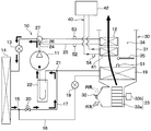
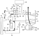
- the vehicle air conditioner 1 of the present embodiment includes a heat pump cycle 10 and an indoor air conditioning unit 30 as main components.
- the heat pump cycle 10 includes a vapor compression refrigeration cycle including a compressor 11, an indoor condenser 12, a first expansion valve 13, an outdoor heat exchanger 14, a second expansion valve 18, an indoor evaporator 19, and an accumulator 22. ing.
- an HFC refrigerant for example, R134a
- a vapor compression subcritical refrigeration cycle in which the refrigerant pressure on the high pressure side in the cycle does not exceed the critical pressure of the refrigerant. It is composed.
- an HFO refrigerant for example, R1234yf
- R1234yf an HFO refrigerant
- the refrigerant of the heat pump cycle 10 is mixed with refrigerating machine oil which is a lubricating oil for lubricating various components inside the compressor 11. A part of the lubricating oil circulates in the cycle together with the refrigerant.
- the compressor 11 which is a component device of the heat pump cycle 10 is disposed in the engine room of the vehicle.
- the compressor 11 performs a function of compressing and discharging the sucked refrigerant in the heat pump cycle 10.
- the compressor 11 is composed of an electric compressor that drives a compression mechanism (not shown) by an electric motor (not shown).
- a compression mechanism various compression mechanisms such as a scroll-type compression mechanism and a vane-type compression mechanism can be employed.
- the electric motor is an AC motor whose operation is controlled by an AC current output from the inverter 80.
- the compressor 11 of this embodiment is connected to the air-conditioning control apparatus 50 via the inverter 80, as shown in FIG.
- the inverter 80 is a device that controls the compressor 11 in accordance with a control signal from the air conditioning control device 50.
- the inverter 80 is configured to be able to adjust the flow rate of the high-pressure refrigerant flowing into the indoor condenser 12 by controlling the compressor 11.
- the inverter 80 can adjust the amount of heat exchange between the high-pressure refrigerant and the blown air in the indoor condenser 12 by changing the flow rate of the high-pressure refrigerant flowing into the indoor condenser 12. Therefore, in the present embodiment, the inverter 80 constitutes a refrigerant flow rate adjustment unit that adjusts the flow rate of the high-pressure refrigerant flowing into the indoor condenser 12, and a heat exchange adjustment unit.
- an indoor condenser 12 is connected to the refrigerant discharge port side of the compressor 11.
- the indoor condenser 12 is arrange
- the indoor condenser 12 is a condenser that heats the blown air after passing through the indoor evaporator 19 by exchanging heat between the high-pressure refrigerant discharged from the compressor 11 and the blown air.
- a first expansion valve 13 is connected to the refrigerant outlet side of the indoor condenser 12.
- the first expansion valve 13 is a decompression mechanism that decompresses the refrigerant flowing out of the indoor condenser 12.
- the first expansion valve 13 includes a valve body configured to be able to change the throttle opening, and an actuator that drives the valve body.
- the first expansion valve 13 of the present embodiment is configured by a variable throttle mechanism that can be set to a throttle state that exhibits a pressure reducing action and a fully open state that does not exhibit a pressure reducing action. Further, the first expansion valve 13 is configured by an electric variable throttle mechanism that is controlled by a control signal output from the air conditioning control device 50.
- the outdoor heat exchanger 14 is connected to the refrigerant outlet side of the first expansion valve 13.
- the outdoor heat exchanger 14 is a heat exchanger that is disposed in the engine room and exchanges heat between the refrigerant that has passed through the first expansion valve 13 and the air outside the vehicle (that is, outside air).
- the outdoor heat exchanger 14 functions as an endothermic heat exchanger that evaporates the low-pressure refrigerant and exerts an endothermic action in the heating mode.
- the outdoor heat exchanger 14 functions as a heat radiating heat exchanger that radiates heat from the high-pressure refrigerant at least in the cooling mode.
- the low-pressure side branching section 15 that branches the flow of the refrigerant that has flowed out of the outdoor heat exchanger 14 is connected to the refrigerant outlet side of the outdoor heat exchanger 14.
- the low-pressure side branching portion 15 is constituted by a three-way joint in which one of the three inlets and outlets is a refrigerant inlet and the remaining two are refrigerant outlets.
- the low pressure side branch section 15 is connected to a low pressure refrigerant passage 16 at one refrigerant outlet and a low pressure bypass passage 17 to the other refrigerant outlet.
- the low-pressure refrigerant passage 16 is a refrigerant passage that guides the refrigerant to an accumulator 22 described later via the second expansion valve 18 and the indoor evaporator 19.
- the second expansion valve 18 is a decompression mechanism that decompresses the refrigerant that has flowed out of the outdoor heat exchanger 14.
- the second expansion valve 18 of the present embodiment is configured by a variable throttle mechanism that can be set to a throttle state that exerts a pressure reducing action and a fully closed state that blocks a refrigerant flow.
- the second expansion valve 18 includes an electric variable throttle mechanism that is controlled by a control signal output from the air conditioning control device 50.
- the indoor evaporator 19 is disposed on the upstream side of the air flow of the indoor condenser 12 in the air conditioning case 31 of the indoor air conditioning unit 30 described later.
- the indoor evaporator 19 is an evaporator that cools the blown air by causing the low-pressure refrigerant that has passed through the second expansion valve 18 to exchange heat with the blown air before passing through the indoor condenser 12 and evaporating the low-pressure refrigerant. is there.
- the low-pressure bypass passage 17 is a refrigerant passage that bypasses the second expansion valve 18 and the indoor evaporator 19 and guides the refrigerant to an accumulator 22 described later.
- the low pressure bypass passage 17 is provided with a low pressure side opening / closing valve 20 for opening and closing the low pressure bypass passage 17.
- the refrigerant flowing out of the outdoor heat exchanger 14 flows into the low-pressure bypass passage 17 when the low-pressure side opening / closing valve 20 is opened and the second expansion valve 18 is fully closed.
- the refrigerant that has flowed out of the outdoor heat exchanger 14 flows into the low-pressure refrigerant passage 16 when the low-pressure side opening / closing valve 20 is closed and the second expansion valve 18 is in the throttle state. Therefore, in this embodiment, the low-pressure side opening / closing valve 20 and the second expansion valve 18 change the passage of the refrigerant flowing out of the outdoor heat exchanger 14 to either the low-pressure refrigerant passage 16 or the low-pressure bypass passage 17. It functions as a part.
- the low-pressure side opening / closing valve 20 may be constituted by a flow path switching valve.
- the flow path switching valve may be disposed in the low pressure side branching section 15 or the low pressure side junction section 21.
- the low-pressure side junction 21 of the low-pressure refrigerant passage 16 and the low-pressure bypass passage 17 is connected to the downstream side of the refrigerant flow of the indoor evaporator 19 and the low-pressure side opening / closing valve 20.
- the low-pressure side junction 21 is composed of a three-way joint in which one of the three inlets and outlets is a refrigerant outlet and the remaining two are refrigerant inlets.
- An accumulator 22 is connected to the refrigerant outlet side of the low-pressure side junction 21.
- the accumulator 22 separates the gas-liquid refrigerant flowing into the accumulator 22 and causes the separated gas-phase refrigerant and lubricating oil contained in the refrigerant to flow out to the refrigerant inlet side of the compressor 11.
- the accumulator 22 also functions as a storage unit that temporarily stores the liquid-phase refrigerant separated in the accumulator 22 so as to temporarily store the excess refrigerant in the cycle. Therefore, the accumulator 22 functions to prevent liquid compression in the compressor 11 by suppressing the liquid phase refrigerant from being sucked into the compressor 11.
- the indoor air conditioning unit 30 is disposed inside the instrument panel (that is, the instrument panel) at the foremost part of the vehicle interior.
- the indoor air conditioning unit 30 has an air conditioning case 31 that forms an outer shell and forms an air passage for the blown air into the vehicle interior.
- an inside / outside air switching device 32 for switching and introducing vehicle interior air (that is, inside air) and outside air is arranged.
- the inside / outside air switching device 32 adjusts the opening ratio of the inside air introduction port and the outside air introduction port with the inside / outside air switching door, thereby changing the air volume ratio between the inside air volume into the air conditioning case 31 and the outside air volume. It is a device to let you.
- a blower 33 that blows air introduced from the inside / outside air switching device 32 toward the vehicle interior is disposed on the downstream side of the air flow of the inside / outside air switching device 32.
- the blower 33 is an electric blower that drives a centrifugal fan 33a such as a sirocco fan by an electric motor 33b.
- the blower 33 is controlled in blowing capacity (for example, the number of rotations) by a control voltage output from the air conditioning control device 50.
- the indoor evaporator 19 On the downstream side of the air flow of the blower 33, the indoor evaporator 19, the heater core 41, and the indoor condenser 12 are arranged in the order of the indoor evaporator 19, the heater core 41, and the indoor condenser 12 with respect to the flow of the blown air. ing.
- the indoor evaporator 19 is disposed on the upstream side of the air flow with respect to the heater core 41 and the indoor condenser 12.
- the heater core 41 is disposed on the upstream side of the air flow with respect to the indoor condenser 12.
- the heater core 41 is disposed in a hot water circuit 40 through which cooling water of the internal combustion engine 42 that outputs driving force for vehicle travel circulates. Note that the heater core 41 is disposed on the downstream side of the cooling water flow of the internal combustion engine 42 in the hot water circuit 40 so that the hot water after passing through the internal combustion engine 42 flows.
- the heater core 41 is a heat exchanger that heats the blown air by exchanging heat between the cooling water flowing out from the internal combustion engine 42 and the blown air.
- the heater core 41 constitutes a heating heat exchanger that heats the blown air before passing through the indoor condenser 12 using a heat source different from the heat pump cycle 10.
- a cold air bypass passage 34 through which the blown air after passing through the indoor evaporator 19 flows around the heater core 41 and the indoor condenser 12.
- an air mix door 35 is disposed on the downstream side of the air flow of the indoor evaporator 19 and on the upstream side of the air flow of the heater core 41 and the indoor condenser 12.
- the air mix door 35 adjusts the air volume ratio between the air volume that passes through the heater core 41 and the indoor condenser 12 and the air volume that passes through the cold air bypass passage 34 in the blown air after passing through the indoor evaporator 19, and enters the vehicle interior. It functions as a temperature adjustment unit that adjusts the temperature of the blown-out air.
- the operation of the air mix door 35 is controlled by a control signal output from the air conditioning control device 50.
- a plurality of opening holes are formed in the most downstream portion of the air-conditioning case 31 to blow out the blown air that has merged in the merge space into the passenger compartment.
- the air conditioning case 31 has, as an opening hole, a defroster opening hole that blows air toward the inner surface of the window glass on the front surface of the vehicle, a face opening hole that blows air conditioned air toward the upper body of the passenger in the vehicle interior, A foot opening hole for blowing air-conditioned air toward the feet is formed.
- a defroster door, a face door, and a foot door are arranged on the upstream side of the air flow of each opening hole as a blowing mode door for adjusting the opening area of each opening hole.
- These blowing mode doors are driven by an actuator whose operation is controlled by a control signal output from the air conditioning control device 50 via a link mechanism or the like (not shown).
- each opening hole is connected to a face air outlet, a foot air outlet, and a defroster air outlet provided in the vehicle interior via ducts that form air passages, respectively.
- the air conditioning control device 50 includes a microcomputer including a storage unit such as a CPU, a ROM, and a RAM and its peripheral circuits.
- the air conditioning control device 50 performs various calculations and processes based on the control program stored in the storage unit, and controls the operation of various air conditioning control devices connected to the output side.
- storage part of the air-conditioning control apparatus 50 is comprised with a non-transitional tangible storage medium.
- a sensor group for air conditioning control is connected to the input side of the air conditioning controller 50.
- the air-conditioning control device 50 includes an internal air sensor that detects the internal air temperature, an external air sensor that detects the external air temperature, and solar radiation that detects the amount of solar radiation inside the vehicle as sensors that detect the state of the environment inside and outside the vehicle. Sensors etc. are connected.
- a sensor for detecting the operating state of the heat pump cycle 10 is connected to the air conditioning control device 50.
- the air conditioning controller 50 includes a first temperature sensor 51 that detects the air temperature after passing through the indoor evaporator 19, a second temperature sensor 52 that detects the temperature of the high-pressure refrigerant flowing into the indoor condenser 12, A refrigerant pressure sensor 53 for detecting the refrigerant pressure after passing through the indoor condenser 12 is connected.
- the air temperature after passing through the indoor evaporator 19 may be referred to as an evaporator temperature Te.
- the temperature of the high-pressure refrigerant that is discharged from the compressor 11 and flows into the indoor condenser 12 may be referred to as discharge refrigerant temperature Th.
- the refrigerant pressure after passing through the indoor condenser 12 may be referred to as a high-pressure refrigerant pressure Ph.
- the discharged refrigerant temperature Th can be interpreted as the refrigerant temperature of the indoor condenser 12.
- the first temperature sensor 51 a sensor that directly detects the temperature of the heat exchange fin of the indoor evaporator 19 as the evaporator temperature Te, or indirectly the temperature of the refrigerant flowing through the indoor evaporator 19 as the evaporator temperature Te.
- a sensor or the like to detect is conceivable, but any sensor may be used.
- the 2nd temperature sensor 52 the sensor which detects the discharge refrigerant
- any sensor may be used.
- a third temperature sensor 54 that detects the temperature of the cooling water flowing into the heater core 41 is connected to the air conditioning control device 50.
- the third temperature sensor 54 is a sensor for calculating the temperature of the blown air before being heated by the heater core 41 and passing through the indoor condenser 12 from the temperature of the cooling water flowing into the heater core 41.
- the temperature of the cooling water flowing into the heater core 41 may be referred to as the heater core water temperature Twh.
- the temperature of the blown air before being heated by the heater core 41 and passing through the indoor condenser 12 may be referred to as the heater core blowing temperature Tca.
- the heater core blowing temperature Tca is slightly lower than the heater core water temperature Twh flowing into the heater core 41 according to the heat exchange efficiency of the indoor condenser 12. For this reason, the air-conditioning control apparatus 50 of this embodiment calculates the temperature which subtracted the predetermined
- the air conditioning control device 50 is connected to an operation panel 60 on which various air conditioning operation switches are arranged.
- the air conditioning controller 50 receives operation signals from various air conditioning operation switches on the operation panel 60.
- an operation switch of the vehicle air conditioner 1 a temperature setting switch for setting a target temperature in the passenger compartment, and whether or not the blown air is cooled by the indoor evaporator 19 are set.
- a / C switch or the like is provided.
- the air-conditioning control device 50 is connected to the vehicle control device 70 that controls the entire vehicle so that bidirectional communication is possible.
- vehicle information such as the operating state of the internal combustion engine 42 and the traveling state of the vehicle are input from the vehicle control device 70 to the air conditioning control device 50.
- the air conditioning control device 50 of the present embodiment is a device in which control units (for example, hardware and software) that control the operation of various control devices connected to the output side are integrated.
- control units for example, hardware and software
- an operation mode switching unit 50a for switching the operation mode of the heat pump cycle 10 by controlling the operation of various control devices
- a compressor control unit 50b for controlling the operation of the inverter 80.
- the operation mode switching unit 50a stops the compressor 11 and heats the blown air by the heater core 41, and operates the compressor 11 and heats the blown air by at least the indoor condenser 12.
- the heating switching part which switches heating is comprised.
- the compressor control part 50b comprises the heat exchange control part which controls the inverter 80 which functions as a heat exchange adjustment part.
- the vehicle air conditioner 1 of the present embodiment can be switched to a cooling mode, a heating mode, and a dehumidifying heating mode. These operation modes can be switched by air conditioning control processing executed by the air conditioning control device 50.
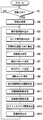
- the air conditioning control processing executed by the air conditioning control device 50 will be described with reference to the flowchart shown in FIG.
- the air conditioning control process is started when the operation switch of the vehicle air conditioner 1 on the operation panel is turned on. Note that each step in the flowchart shown in FIG. 3 is realized by the air conditioning control device 50, and each function realized in each step can be interpreted as a function realizing unit.
- the air-conditioning control device 50 determines whether or not the operation switch of the vehicle air-conditioning device 1 is turned on (that is, air-conditioning is turned on) (S1). As a result, if it is determined that the operation switch of the vehicle air conditioner 1 is turned on, the air conditioning control device 50 initializes flags, timers, and the like stored in the storage unit, and initializes the initial positions of various control devices. (S2). In this initialization process, it may be adjusted to the value stored in the storage unit when the previous operation of the vehicle air conditioner 1 was stopped.
- the air conditioning control device 50 reads the operation signal of the operation panel 60 (S3). Moreover, the air-conditioning control apparatus 50 reads each sensor signal of the sensor group for air-conditioning control (S4). And the air-conditioning control apparatus 50 calculates the target blowing temperature TAO of the blowing air which blows off into a vehicle interior based on the various signals read by the process of step S3, S4 (S5).
- the target blowing temperature TAO is calculated using the following formula F1.
- TAO Kset ⁇ Tset ⁇ Kr ⁇ Tr ⁇ Kam ⁇ Tam ⁇ Ks ⁇ As + C (F1)
- Tset is a target temperature set in the vehicle interior set by the temperature setting switch
- Tr is a detection signal detected by the inside air sensor
- Tam indicates a detection signal detected by the outside air sensor
- As indicates a detection signal detected by the solar radiation sensor.
- Kset, Kr, Kam, and Ks are control gains
- C is a correction constant.
- the air conditioning control device 50 determines the blowing capacity of the blower 33 (S6).
- the blowing capacity of the blower 33 is determined with reference to a control map stored in advance in the storage unit.
- the air conditioning control device 50 determines the air blowing capacity near the maximum capacity so that the air blowing amount of the blower 33 increases when the target blowing temperature TAO is in the extremely low temperature region and the extremely high temperature region.
- the air conditioning control device 50 of the present embodiment is configured such that when the target blowing temperature TAO rises from the extremely low temperature range to the intermediate temperature range, or falls from the extremely high temperature range to the intermediate temperature range, the air flow rate of the blower 33 is increased.
- the air blowing capacity is determined to be lower than near the maximum so as to decrease.
- the air conditioning control device 50 determines a suction port mode indicating the switching state of the inside / outside air switching device 32 (S7).
- the suction port mode is determined with reference to the control map stored in advance in the storage unit based on the target outlet temperature TAO.
- the air conditioning control device 50 of the present embodiment basically determines the suction port mode as the outside air mode for introducing outside air.
- the target blowing temperature TAO is in a very low temperature range and high cooling performance is required, or the target blowing temperature TAO is in a very high temperature range and high heating performance is required.
- the inlet mode is determined as the inside air mode for introducing the inside air into the air.
- the air conditioning control device 50 determines the outlet mode (S8).
- the outlet mode is determined with reference to the control map stored in advance in the storage unit based on the target outlet temperature TAO.
- the air-conditioning control device 50 determines the outlet mode so that the mode changes from the foot mode to the bi-level mode to the face mode as the target outlet temperature TAO decreases from the high temperature region to the low temperature region.
- the air conditioning control device 50 determines the operation mode of the vehicle air conditioner 1 based on the various signals read in steps S3 and S4 and the target outlet temperature TAO calculated in step S5 (S9).
- step S9 when the A / C switch is turned on and the target blowing temperature TAO is lower than a predetermined cooling reference value, the cooling mode for performing indoor cooling is determined. Moreover, in the process of step S9, when the A / C switch is turned on and the target blowing temperature TAO is equal to or higher than the cooling reference value, the dehumidifying heating mode for performing the dehumidifying heating in the room is determined. Furthermore, in the process of step S9, when the A / C switch is turned off and the target outlet temperature TAO is equal to or higher than the heating reference value, the heating mode in which room heating is performed is determined.
- the air conditioning control device 50 determines the open / close state of the low-pressure side open / close valve 20 based on the operation mode determined in step S9 (S10).
- step S10 as shown in FIG. 4, when the cooling mode and the dehumidifying heating mode are determined in the process of step S9, the low-pressure side on-off valve 20 is determined to be closed.
- the heating mode is determined in the process of step S9, the low-pressure side on-off valve 20 is determined to be in the open state.
- the air conditioning control device 50 determines the rotational speed of the compressor 11 based on the various signals read in steps S3 and S4, the target outlet temperature TAO calculated in step S5, and the operation mode determined in step S9. (S11).
- the rotational speed of the compressor 11 is determined as follows.
- the target evaporator temperature TEO of the indoor evaporator 19 is determined based on the target outlet temperature TAO with reference to a control map stored in advance in the storage unit.
- the target evaporator temperature TEO is determined to be a temperature (for example, 1 ° C.) higher than the frost formation temperature (for example, 0 ° C.) in order to prevent frost formation (that is, frost) of the indoor evaporator 19.
- step S11 based on the deviation between the target evaporator temperature TEO and the evaporator temperature Te detected by the first temperature sensor 51, the compressor is set so that the evaporator temperature Te approaches the target evaporator temperature TEO. 11 is determined.
- step S11 when the heating mode is determined in the process of step S9, the rotation speed of the compressor 11 is determined based on the heater core blowing temperature Tca, the high-pressure refrigerant pressure Pd, the target blowing temperature TAO, and the discharge refrigerant temperature Th. To decide.
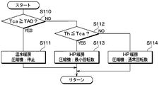
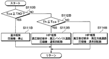
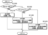
- step S11 when the heating mode is determined in the process of step S9 will be described using the flowchart of FIG.
- the control routine shown in FIG. 5 has shown the processing content which the air-conditioning control apparatus 50 processes in step S11, when it determines with heating mode by the process of step S9.
- the air-conditioning control device 50 first calculates the heater blowing temperature Tca from the heater core water temperature Twh detected by the third temperature sensor 54, and the calculated heater blowing temperature Tca is equal to or higher than the target blowing temperature TAO. It is determined whether or not (S110).
- the air-conditioning control apparatus 50 determines the rotation speed of the compressor 11 to zero. That is, when the condition that the heater core blowing temperature Tca is higher than the target blowing temperature TAO is satisfied, the air conditioning control device 50 stops the compressor 11 and heats the blown air using the internal combustion engine 42 as a heat source. (S111).
- the air-conditioning control apparatus 50 operates the compressor 11, and HP heating which heats blowing air with the indoor condenser 12 is carried out. Switch to.
- the blown air temperature TAV which is the temperature of the air blown from the indoor air conditioning unit 30 into the vehicle interior, may decrease. This point will be described with reference to FIG. FIG. 6 shows an example of changes in the blown air temperature TAV, the target blown temperature TAO, the heater core blown temperature Tca, and the discharge refrigerant temperature Th when switching from hot water heating to HP heating.
- the indoor condenser 12 is the only heat exchanger that functions as a radiator that dissipates the refrigerant. For this reason, in the heat pump cycle 10, in the steady state where the rotation speed of the compressor 11 is stable, the discharge refrigerant temperature Th is balanced so as to be higher than the heater core blowing temperature Tca.
- the refrigerant in the cycle is at a temperature or pressure corresponding to the ambient temperature around it. For this reason, the discharged refrigerant temperature Th may be lower than the heater core blowing temperature Tca.
- the air conditioning control device 50 of the present embodiment has a high-pressure refrigerant and blown air in the indoor condenser 12. To reduce the amount of heat exchange.
- the air conditioning control device 50 determines whether or not the discharged refrigerant temperature Th detected by the second temperature sensor 52 is equal to or lower than the heater core blowing temperature Tca (S112). As a result, when it is determined that the discharged refrigerant temperature Th is equal to or lower than the heater core blowing temperature Ta, the air conditioning control device 50 determines the rotation speed of the compressor 11 as the minimum rotation speed (S113).
- the rotation speed of the compressor 11 is determined to be the minimum rotation speed, the flow rate of the refrigerant flowing into the indoor condenser 12 decreases. Thereby, since the amount of heat absorption from the blown air in the indoor condenser 12 is reduced, it is possible to suppress the temperature drop of the blown air temperature TAV.
- step S112 when it is determined in the determination process in step S112 that the discharged refrigerant temperature Th is higher than the heater core blowing temperature Ta, the refrigerant does not absorb heat from the blown air in the indoor condenser 12. For this reason, when it determines with discharge refrigerant
- step S114 based on the high-pressure refrigerant pressure Ph detected by the refrigerant pressure sensor 53 and the target outlet temperature TAO, the control map stored in advance in the storage unit is referred to and the high-pressure refrigerant pressure Ph is set. A target pressure Phd is determined.
- step S114 the rotational speed of the compressor 11 is determined based on the deviation between the target pressure Phd and the high-pressure refrigerant pressure Ph so that the high-pressure refrigerant pressure Ph approaches the target pressure Phd.
- the opening degree of each expansion valve 13 is determined (S12).
- the first expansion valve 13 is fully opened and the second expansion valve 18 is determined to be in the throttle state.
- the throttle opening degree of the second expansion valve 18 is determined so that the degree of supercooling of the refrigerant flowing into the second expansion valve 18 approaches the target supercooling temperature.
- the target degree of supercooling is determined with reference to a control map stored in advance in the storage unit based on the outside air temperature detected by the outside air sensor.
- step S12 when the heating mode is determined in the process of step S9, the first expansion valve 13 is set in the throttle state and the second expansion valve 18 is determined in the fully closed state.
- the throttle opening degree of the first expansion valve 13 is determined so that the degree of supercooling of the refrigerant flowing into the first expansion valve 13 approaches the target supercooling temperature.
- the target degree of supercooling is determined with reference to a control map stored in advance in the storage unit based on the detected value of the outside air temperature sensor, etc., as in the cooling mode.
- the air conditioning control device 50 determines the opening degree of the air mix door 35 (S13).
- the air mix door 35 closes the air passage of the heater core 41 and the indoor condenser 12, and the entire flow rate of the blown air after passing through the indoor evaporator 19 passes through the cold air bypass passage 34. To be determined.
- step S13 the air mix door 35 closes the cold air bypass passage 34 in the dehumidifying heating mode or the heating mode, and the total flow rate of the blown air after passing through the indoor evaporator 19 is the heater core 41 and the indoor condenser. 12 is determined to pass.
- the door opening SW of the air mix door 35 may be determined according to the target blowing temperature TAO, the evaporator temperature Te, and the heater core water temperature Twh. Specifically, the door opening degree SW may be calculated using the following formula F2.
- SW ⁇ (TAO-Te) / (Twh-Te) ⁇ ⁇ 100 [%] (F2)
- SW ⁇ 0 [%] is the maximum cooling position of the air mix door 35 that fully opens the cold air bypass passage 34.
- SW ⁇ 100 [%] is the maximum heating position of the air mix door 35 that fully opens the air passages of the heater core 41 and the indoor condenser 12.
- the air conditioning control device 50 outputs the control signals determined in steps S6 to S13 to various control devices (S14). Thereafter, the air-conditioning control device 50 repeats the control processing of steps S3 to S13 at a predetermined cycle until the operation panel 60 requests to stop the operation of the vehicle air-conditioning device 1.
- the air conditioning control device 50 outputs the control signal related to the rotation speed of the compressor 11 to the inverter 80.
- the inverter 80 controls the rotation speed of the compressor 11 according to the control signal output from the air conditioning control device 50.
- the vehicle air conditioner 1 of the present embodiment is controlled as described above. For this reason, the vehicle air conditioner 1 operates as follows according to the operation mode selected in step S9.
- (A) Cooling Mode In the cooling mode, the air conditioning control device 50 is in a state where the low-pressure side opening / closing valve 20 is closed, the first expansion valve 13 is fully opened, and the second expansion valve 18 is in the throttled state. To operate. Therefore, in the cooling mode, as shown by the arrow in FIG. 9, the refrigerant discharged from the compressor 11 is discharged from the indoor condenser 12 ⁇ the first expansion valve 13 ⁇ the outdoor heat exchanger 14 ⁇ the second expansion valve 18 ⁇ the indoor evaporation. It flows in the order of the container 19 ⁇ accumulator 22 and is sucked into the compressor 11 again.
- the refrigerant discharged from the compressor 11 flows into the indoor condenser 12 during the cooling mode.
- the air mix door 35 closes the air passages of the heater core 41 and the indoor condenser 12
- the refrigerant flowing into the indoor condenser 12 flows out of the indoor condenser 12 without radiating heat to the blown air. .
- the refrigerant that has flowed out of the indoor condenser 12 flows into the outdoor heat exchanger 14 without being almost decompressed by the first expansion valve 13 because the first expansion valve 13 is fully open.
- the refrigerant that has flowed into the outdoor heat exchanger 14 radiates heat by exchanging heat with the outside air, and is cooled until the target degree of subcooling is reached.
- the refrigerant flowing out of the outdoor heat exchanger 14 is reduced in pressure until it flows into the second expansion valve 18 and becomes a low-pressure refrigerant because the low-pressure side opening / closing valve 20 is closed and the second expansion valve 18 is in a throttle state. Is done.
- the low-pressure refrigerant that has flowed out of the second expansion valve 18 flows into the indoor evaporator 19, absorbs heat from the blown air blown from the blower 33, and evaporates. Thereby, blowing air is cooled and dehumidified.
- the refrigerant that has flowed out of the indoor evaporator 19 flows into the accumulator 22 and is separated into gas and liquid. Then, the gas-phase refrigerant separated by the accumulator 22 is sucked into the compressor 11 and compressed again.
- the liquid-phase refrigerant separated by the accumulator 22 is stored inside the accumulator 22 as an unnecessary surplus refrigerant in order to exhibit the refrigerating capacity required by the heat pump cycle 10. The same applies to the dehumidifying heating mode and the heating mode.
- the refrigerant is radiated by the outdoor heat exchanger 14, and the refrigerant is evaporated by the indoor evaporator 19, whereby the blown air blown into the vehicle interior is cooled. Thereby, cooling of a vehicle interior is realizable.
- (B) Dehumidifying heating mode In the dehumidifying heating mode, the air conditioning control device 50 performs compression in a state where the low-pressure side opening / closing valve 20 is closed, the first expansion valve 13 is fully opened, and the second expansion valve 18 is in a throttled state. The machine 11 is operated. For this reason, at the time of dehumidification heating mode, a refrigerant
- the high-pressure refrigerant discharged from the compressor 11 flows into the indoor condenser 12 during the dehumidifying heating mode.
- the air mix door 35 fully opens the air passage of the heater core 41 and the indoor condenser 12
- the refrigerant flowing into the indoor condenser 12 exchanges heat with the blown air that has passed through the heater core 41 to dissipate heat. Thereby, it blows so that blowing air may approach target blowing temperature TAO.
- the refrigerant that has flowed out of the indoor condenser 12 flows into the outdoor heat exchanger 14 through the first expansion valve 13 as in the cooling mode.
- coolant which flowed into the outdoor heat exchanger 14 heat-exchanges with external air, radiates heat, and is cooled until it becomes a target supercooling degree.
- the refrigerant that has flowed out of the outdoor heat exchanger 14 flows in the order of the second expansion valve 18 ⁇ the indoor evaporator 19 ⁇ the accumulator 22 ⁇ the compressor 11 as in the cooling mode.
- the refrigerant is radiated by the indoor condenser 12 and the outdoor heat exchanger 14, and the refrigerant is evaporated by the indoor evaporator 19, so that it is cooled and dehumidified by the indoor evaporator 19.
- the blown air is heated in the indoor condenser 12.
- (C) Heating mode In the heating mode, the air-conditioning control device 50 opens the low-pressure side opening / closing valve 20, opens the first expansion valve 13, and fully closes the second expansion valve 18. In this state, the air-conditioning control device 50 performs hot water heating that heats the blown air using the internal combustion engine 42 as a heat source according to the heater core blowout temperature Tca and the target blowout temperature TAO, and HP heating that heats the blown air using the indoor condenser 12. And switch.
- the air conditioning control device 50 stops the compressor 11 and performs hot water heating using the internal combustion engine 42 as a heat source. In this hot water heating, the cooling air of the internal combustion engine 42 is exchanged with the blown air by the heater core 41, and the blown air is heated. Thereby, heating of a vehicle interior is realizable.
- the air conditioning control device 50 operates the compressor 11 to switch from hot water heating to HP heating.
- HP heating as shown by the arrows in FIG. 10, the refrigerant discharged from the compressor 11 flows in the order of the indoor condenser 12 ⁇ the first expansion valve 13 ⁇ the outdoor heat exchanger 14 ⁇ the accumulator 22, and again to the compressor 11. Inhaled.
- the air conditioning control device 50 sets the compressor 11 to the minimum rotation speed so that the heat exchange amount between the refrigerant and the blown air in the indoor condenser 12 is reduced. Set to. In this case, the refrigerant that has flowed into the indoor condenser 12 flows out of the indoor condenser 12 with almost no heat absorption from the blown air.
- the air conditioning control device 50 sets the rotation speed of the compressor 11 to the normal rotation speed. In this case, the high-pressure refrigerant flowing into the indoor condenser 12 radiates heat to the blown air. Thereby, in the indoor condenser 12, the blown air is heated so as to approach the target blowing temperature TAO.
- the refrigerant flowing out of the indoor condenser 12 is decompressed until it flows into the first expansion valve 13 and becomes a low-pressure refrigerant because the first expansion valve 13 is in the throttle state.
- the low-pressure refrigerant that has flowed out of the first expansion valve 13 flows into the outdoor heat exchanger 14.
- the refrigerant flowing into the outdoor heat exchanger 14 exchanges heat with the outside air and absorbs heat to evaporate.
- the refrigerant that has flowed out of the outdoor heat exchanger 14 flows into the accumulator 22 and is separated into gas and liquid because the low-pressure side opening / closing valve 20 is open and the second expansion valve 18 is fully closed. Then, the gas-phase refrigerant separated by the accumulator 22 is sucked into the compressor 11 and compressed again.
- the blown air is heated by at least one of the heater core 41 and the indoor condenser 12 unless the discharged refrigerant temperature Th is equal to or lower than the heater core blowing temperature Tca.
- the rotational speed of the compressor 11 is reduced and flows into the indoor condenser 12. Reduce refrigerant flow. According to this, the amount of heat absorption from the blown air in the indoor condenser 12 can be suppressed, and a decrease in the blown air temperature TAV from the indoor air conditioning unit 30 can be suppressed.
- the vehicle air conditioner 1 of the present embodiment described above performs HP heating and the condition that the discharged refrigerant temperature Th is equal to or lower than the heater core blowing temperature Tca is satisfied, the refrigerant and the blown air in the indoor condenser 12 The heat exchange amount is reduced.
- the amount of heat exchange between the high-pressure refrigerant and the blown air in the indoor condenser 12 is reduced by reducing the rotation speed of the compressor 11. It is configured to decrease. According to this, power consumption in the compressor 11 can be reduced while suppressing unnecessary heat exchange between the high-pressure refrigerant and the blown air in the indoor condenser 12.
- the HP heating when the HP heating is performed, if the discharged refrigerant temperature Th exceeds the heater core blowing temperature Tca, the heat exchange amount between the refrigerant and the blown air in the indoor condenser 12 is increased. According to this, the air temperature TAV blown into the vehicle compartment during HP heating can be brought close to the target air temperature TAO.
- the example of calculating the heater core blowing temperature Tca from the heater core water temperature Twh detected by the third temperature sensor 54 has been described, but the present invention is not limited to this.
- a temperature sensor that detects the temperature of the heat exchange fins of the heater core 41 may be provided, and the heater core blowing temperature Tca may be directly detected by the temperature sensor.
- the heater core water temperature Twh detected by the third temperature sensor 54 may be detected as the heater core blowing temperature Tca. The same applies to the following embodiments.
- the saturated refrigerant temperature in the indoor condenser 12 may be calculated based on the high-pressure refrigerant pressure Ph detected by the refrigerant pressure sensor 53, and the saturated refrigerant temperature may be used as the discharge refrigerant temperature Th. The same applies to the following embodiments.
- the present invention when the condition that the discharged refrigerant temperature Th is equal to or lower than the heater core blowing temperature Tca is satisfied during HP heating, it is desirable to set the rotation speed of the compressor 11 to the minimum rotation speed, but the present invention is not limited to this.
- the rotation speed of the compressor 11 is increased, and the normal rotation speed of the compressor 11 when the discharged refrigerant temperature Th exceeds the heater core blowing temperature Tca.
- a lower rotation speed may be used.
- the rotation speed of the compressor 11 may be set to a rotation speed obtained by subtracting a predetermined value from the normal rotation speed of the compressor 11.
- the present invention is not limited to this.
- the discharged refrigerant temperature Th at the start of the heat pump cycle 10 is close to the ambient temperature (for example, outside air).
- the air-conditioning control device 50 may compare the outside air temperature and the heater core blowing temperature Tca to determine whether or not the condition that the discharged refrigerant temperature Th is equal to or lower than the heater core blowing temperature Tca is satisfied.
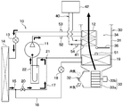
- a water refrigerant heat exchanger 23 is connected to the refrigerant discharge port side of the compressor 11.
- the water refrigerant heat exchanger 23 is a heat exchanger that exchanges heat between the high-pressure refrigerant discharged from the compressor 11 and the cooling water of the internal combustion engine 42.
- the cooling water of the internal combustion engine 42 corresponds to a heating medium that heats the blown air blown into the vehicle interior that is the air-conditioning target space. Therefore, in this embodiment, the water refrigerant heat exchanger 23 functions as a condenser that exchanges heat between the high-pressure refrigerant discharged from the compressor 11 and the cooling water.
- the water-refrigerant heat exchanger 23 of the present embodiment is a cooling water in which the cooling water after passing through the refrigerant-side passage 23a through which the high-pressure refrigerant discharged from the compressor 11 flows and the internal combustion engine 42 that constitutes the heating source flows. Side passage 23b.
- the refrigerant side passage 23 a is provided between the compressor 11 and the first expansion valve 13 in the heat pump cycle 10. Specifically, the refrigerant side passage 23 a has a refrigerant inlet side connected to the refrigerant discharge port side of the compressor 11, and a refrigerant outlet side connected to the refrigerant inlet side of the first expansion valve 13.
- the cooling water side passage 23 b is provided between the internal combustion engine 42 and the heater core 41 in the hot water circuit 40. Specifically, the cooling water side passage 23 b has a cooling water inlet side connected to the cooling water outlet side of the internal combustion engine 42, and a cooling water outlet side connected to the cooling water inlet side of the heater core 41.
- the hot water circuit 40 of the present embodiment is provided with a fourth temperature sensor 55 that detects the temperature of the cooling water flowing into the water-refrigerant heat exchanger 23 (that is, the temperature of the heating medium).
- the temperature of the cooling water flowing into the water / refrigerant heat exchanger 23 may be referred to as a cooling water temperature Twe.
- the fourth temperature sensor 55 is connected to the air conditioning controller 50 as shown in FIG.
- the air conditioning control device 50 is configured to be able to read the detection value of the fourth temperature sensor 55.
- the indoor air conditioning unit 30 of the present embodiment the indoor evaporator 19 and the heater core 41 are disposed in the air conditioning case 31, and the water refrigerant heat exchanger 23 is disposed outside the air conditioning case 31.
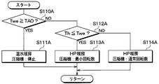
- control process at the time of the heating mode of this embodiment is demonstrated with reference to FIG.
- the control routine shown in FIG. 13 shows the processing contents when the air conditioning control device 50 determines the operation mode to be the heating mode.
- the air conditioning control device 50 first determines whether or not the coolant temperature Twe detected by the fourth temperature sensor 55 is equal to or higher than the target outlet temperature TAO (S110A). As a result, when it is determined that the cooling water temperature Twe is equal to or higher than the target blowing temperature TAO, the vehicle interior can be heated by hot water heating using the internal combustion engine 42. For this reason, when it determines with cooling water temperature Twe being more than the target blowing temperature TAO, the air-conditioning control apparatus 50 determines the rotation speed of the compressor 11 to zero.
- the air conditioning control device 50 stops the compressor 11 and determines hot water heating that heats the blown air using the internal combustion engine 42 as a heat source. (S111A).
- the air conditioning control device 50 operates the compressor 11 and cools it with the refrigerant flowing through the water-refrigerant heat exchanger 23. Switch to HP heating to heat water.
- the temperature of the refrigerant in the cycle may be lower than the cooling water temperature Twe.
- the compressor 11 When the compressor 11 is operated in a state where the temperature of the refrigerant in the cycle is lower than the cooling water temperature Twe, the refrigerant having a temperature lower than the cooling water temperature Twe circulates in the cycle. At this time, the refrigerant having a temperature lower than the cooling water temperature Twe continues to flow into the water refrigerant heat exchanger 23. For this reason, in the water refrigerant heat exchanger 23, the state in which the refrigerant flowing through the water refrigerant heat exchanger 23 absorbs heat from the cooling water is continued until the discharged refrigerant temperature Th becomes higher than the cooling water temperature Twe. In this case, the temperature of the cooling water flowing into the heater core 41 is lowered, so that the blown air temperature TAV is lowered.
- the air conditioning control device 50 determines whether or not the discharged refrigerant temperature Th is equal to or lower than the cooling water temperature Twe (S112A). As a result, when it is determined that the discharged refrigerant temperature Th is equal to or lower than the cooling water temperature Twe, the air conditioning control device 50 determines the rotation speed of the compressor 11 as the minimum rotation speed (S113A).
- the rotation speed of the compressor 11 is determined to be the minimum rotation speed, the flow rate of the refrigerant flowing into the water-refrigerant heat exchanger 23 decreases. According to this, since the amount of heat absorption from the cooling water in the water / refrigerant heat exchanger 23 decreases, the temperature drop of the cooling water flowing into the heater core 41 can be suppressed. As a result, it is possible to suppress the temperature drop of the blown air temperature TAV.
- step S112A when it is determined in step S112A that the discharged refrigerant temperature Th is higher than the cooling water temperature Twe, the high-pressure refrigerant does not absorb heat from the cooling water in the water refrigerant heat exchanger 23. For this reason, when it determines with discharge refrigerant
- a high pressure refrigerant pressure Ph is referred to by referring to a control map stored in advance in the storage unit.
- the target pressure Phd is determined.
- the rotation speed of the compressor 11 is determined based on the deviation between the target pressure Phd and the high-pressure refrigerant pressure Ph so that the high-pressure refrigerant pressure Ph approaches the target pressure Phd.
- the heat exchange between the high-pressure refrigerant and the cooling water in the water refrigerant heat exchanger 23 is performed by reducing the rotation speed of the compressor 11. The amount is reduced. According to this, power consumption in the compressor 11 can be reduced while suppressing unnecessary heat exchange between the high-pressure refrigerant and the cooling water in the water-refrigerant heat exchanger 23.
- the HP heating when the HP heating is performed, if the discharged refrigerant temperature Th exceeds the cooling water temperature Twe, the heat exchange amount between the refrigerant and the cooling water in the water refrigerant heat exchanger 23 is increased. According to this, the air temperature TAV blown into the vehicle compartment during HP heating can be brought close to the target air temperature TAO.
- the present invention when the condition that the discharged refrigerant temperature Th is equal to or lower than the cooling water temperature Twe is established during HP heating, it is desirable to set the rotation speed of the compressor 11 to the minimum rotation speed, but the present invention is not limited to this.
- the rotation speed of the compressor 11 is increased, and the normal rotation speed of the compressor 11 when the discharged refrigerant temperature Th exceeds the cooling water temperature Twe.
- a lower rotation speed may be used.
- the rotation speed of the compressor 11 may be set to a rotation speed obtained by subtracting a predetermined value from the normal rotation speed of the compressor 11.
- the present invention is not limited to this.
- the discharged refrigerant temperature Th at the start of the heat pump cycle 10 is close to the ambient temperature (for example, outside air).
- the air conditioning control device 50 may compare the outside air temperature with the cooling water temperature Twe to determine whether or not the condition that the discharged refrigerant temperature Th is equal to or lower than the cooling water temperature Twe is satisfied.
- the present embodiment is different from the first embodiment in that a refrigerant passage for flowing refrigerant to the indoor condenser 12 and a refrigerant passage for flowing refrigerant bypassing the indoor condenser 12 can be switched.
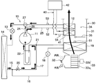
- the heat pump cycle 10 of the present embodiment is provided with a high-pressure side branch portion 24 on the refrigerant discharge port side of the compressor 11.
- the high-pressure branch 24 is a branch that branches the flow of the refrigerant discharged from the compressor 11.
- the high-pressure side branch portion 24 is configured by a three-way joint similar to the low-pressure side branch portion 15.
- the high-pressure side branch section 24 has a high-pressure refrigerant passage 25 connected to one refrigerant outlet and a high-pressure bypass passage 26 connected to the other refrigerant outlet.
- the high-pressure refrigerant passage 25 is a refrigerant passage that guides the high-pressure refrigerant discharged from the compressor 11 to the first expansion valve 13 via the indoor condenser 12.
- the high-pressure bypass passage 26 is a refrigerant passage that guides the high-pressure refrigerant discharged from the compressor 11 to the first expansion valve 13 by bypassing the indoor condenser 12.
- a high-pressure side switching valve 27 that functions as a junction between the high-pressure refrigerant passage 25 and the high-pressure bypass passage 26 is provided.
- the high-pressure side switching valve 27 is a passage switching unit that switches the refrigerant passage of the high-pressure refrigerant discharged from the compressor 11 to one of the high-pressure refrigerant passage 25 and the high-pressure bypass passage 26.
- the high-pressure side switching valve 27 of this embodiment is connected to an air conditioning control device 50 as shown in FIG.
- the high pressure side switching valve 27 of the present embodiment is configured by an electric flow path switching valve controlled by a control signal output from the air conditioning control device 50.
- the high-pressure side switching valve 27 of the present embodiment is configured to be able to adjust the flow rate of the high-pressure refrigerant flowing into the indoor condenser 12 by a control signal from the air conditioning control device 50.
- the high-pressure side switching valve 27 can adjust the amount of heat exchange between the high-pressure refrigerant and the blown air in the indoor condenser 12 by changing the flow rate of the high-pressure refrigerant flowing into the indoor condenser 12. Yes. That is, the high-pressure side switching valve 27 of the present embodiment is configured to be able to adjust the flow rate ratio between the high-pressure refrigerant that flows to the indoor condenser 12 and the high-pressure refrigerant that flows to the high-pressure bypass passage 26.
- the high-pressure bypass passage 26 and the high-pressure side switching valve 27 constitute a refrigerant flow rate adjustment unit that adjusts the flow rate of the high-pressure refrigerant flowing into the indoor condenser 12 and a heat exchange adjustment unit.
- the air-conditioning control device 50 switches the high-pressure side so that the refrigerant discharged from the compressor 11 flows into the high-pressure bypass passage 26 when the indoor condenser 12 is in a cooling mode in which heat exchange between the high-pressure refrigerant and the blown air is not performed.
- the valve 27 is controlled.
- the air conditioning control device 50 allows the refrigerant discharged from the compressor 11 to pass through the high-pressure refrigerant passage 25 to the indoor condenser 12 during the operation mode in which heat exchange is performed between the high-pressure refrigerant and the blown air in the indoor condenser 12.
- the high pressure side switching valve 27 is controlled to flow.
- the switching control unit 50c controls the high-pressure side switching valve 27 in addition to the operation mode switching unit 50a and the compressor control unit 50b.
- the switching control unit 50c constitutes a heat exchange control unit that controls the high-pressure side switching valve 27 that functions as a heat exchange adjustment unit.
- control process at the time of the heating mode of this embodiment is demonstrated with reference to FIG.
- the control routine shown in FIG. 16 shows the processing contents when the air conditioning control device 50 determines the operation mode to be the heating mode.
- the air conditioning control device 50 calculates the heater blowing temperature Tca from the heater core water temperature Twh detected by the third temperature sensor 54, and whether or not the calculated heater blowing temperature Tca is equal to or higher than the target blowing temperature TAO. Is determined (S110B). As a result, when it is determined that the heater core blowing temperature Tca is equal to or higher than the target blowing temperature TAO, the air conditioning control device 50 determines the rotation speed of the compressor 11 to be zero. That is, when the condition that the heater core blowing temperature Tca is equal to or higher than the target blowing temperature TAO is satisfied, the air conditioning control device 50 stops the compressor 11 and determines hot water heating that heats the blown air using the internal combustion engine 42 as a heat source. (S111B).
- the air conditioning control device 50 operates the compressor 11 and heats the blown air with the refrigerant flowing through the indoor condenser 12. Switch to HP heating.
- the air conditioning control device 50 when switching from hot water heating to HP heating, if the condition that the discharged refrigerant temperature Th is equal to or lower than the heater core blowing temperature Tca is satisfied, the air conditioning control device 50 heats the high-pressure refrigerant and the blown air in the indoor condenser 12. Implement a process to reduce the exchange amount.
- the air-conditioning control device 50 determines whether or not the discharged refrigerant temperature Th is equal to or lower than the heater core blowing temperature Tca (S112B). As a result, when it is determined that the discharged refrigerant temperature Th is equal to or lower than the heater core blowing temperature Tca, the air conditioning control device 50 controls the high pressure side switching valve 27 so that the discharged refrigerant from the compressor 11 flows into the high pressure bypass passage 26. (S113B). At this time, for the compressor 11, the rotation speed of the compressor 11 is determined to be the normal rotation speed so that the high-pressure refrigerant pressure Ph approaches the target pressure Phd.
- the refrigerant passage of the refrigerant discharged from the compressor 11 is set to the high-pressure bypass passage 26, the refrigerant does not flow into the indoor condenser 12. According to this, since the high-pressure refrigerant and the blown air do not exchange heat in the indoor condenser 12, it is possible to suppress the temperature drop of the blown air temperature TAV.
- step S112B when it is determined in step S112B that the discharged refrigerant temperature Th is higher than the heater core outlet temperature Tca, the high-pressure refrigerant does not absorb heat from the blown air in the indoor condenser 12. For this reason, when it is determined that the discharged refrigerant temperature Th is higher than the heater core blowing temperature Tca, the air conditioning control device 50 causes the high-pressure side switching valve 27 so that the discharged refrigerant from the compressor 11 flows into the high-pressure refrigerant passage 25. Is controlled (S114B). At this time, for the compressor 11, the rotation speed of the compressor 11 is determined to be the normal rotation speed so that the high-pressure refrigerant pressure Ph approaches the target pressure Phd.
- the vehicle air conditioner 1 of the present embodiment is controlled as described above. For this reason, the vehicle air conditioner 1 operates as follows during HP heating.
- the air conditioning control device 50 operates the compressor 11 to switch from hot water heating to HP heating.
- the air conditioning control device 50 sets the refrigerant passage of the high-pressure refrigerant discharged from the compressor 11 to the high-pressure bypass passage 26.
- the refrigerant discharged from the compressor 11 flows in the order of the first expansion valve 13 ⁇ the outdoor heat exchanger 14 ⁇ the accumulator 22 as shown by the arrow in FIG.
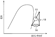
- the heat pump cycle 10 is a hot gas operation in which the work of the compressor 11 is radiated by the outdoor heat exchanger 14.
- the indoor condenser 12 has a cycle configuration in which the refrigerant and the blown air do not exchange heat.
- the air conditioning control device 50 sets the refrigerant passage of the high-pressure refrigerant discharged from the compressor 11 to the high-pressure refrigerant passage 25.
- the refrigerant discharged from the compressor 11 flows in the order of the indoor condenser 12 ⁇ the first expansion valve 13 ⁇ the outdoor heat exchanger 14 ⁇ the accumulator 22 as shown by the arrow in FIG. Is done.
- the refrigerant flowing into the indoor condenser 12 radiates heat to the blown air.
- the blower air is heated by the indoor condenser 12 so as to approach the target blowing temperature TAO.
- the refrigerant and the blown air in the indoor condenser 12 are satisfied when the condition that the discharged refrigerant temperature Th is equal to or lower than the heater core blowing temperature Tca is satisfied.
- the heat exchange amount is reduced.
- the indoor condensing is performed by flowing the refrigerant bypassing the indoor condenser 12.
- the unit 12 is configured not to exchange heat between the high-pressure refrigerant and the cooling water. According to this, unnecessary heat exchange between the high-pressure refrigerant and the blown air in the indoor condenser 12 can be prevented, and a decrease in the blown air temperature TAV can be effectively suppressed.
- the high-pressure refrigerant when HP heating is performed, when the discharged refrigerant temperature Th exceeds the heater core blowing temperature Tca, the high-pressure refrigerant is caused to flow through the indoor condenser 12. According to this, the air temperature TAV blown into the vehicle compartment during HP heating can be brought close to the target air temperature TAO.
- a refrigerant passage for flowing a refrigerant to the water-refrigerant heat exchanger 23 and a refrigerant passage for flowing the refrigerant bypassing the water-refrigerant heat exchanger 23 May be configured to be switchable.
- the high-pressure side switching valve 27 is provided at the junction of the high-pressure refrigerant passage 25 and the high-pressure bypass passage 26 , but the present invention is not limited to this.
- the high pressure side switching valve 27 may be provided at a branch portion between the high pressure refrigerant passage 25 and the high pressure bypass passage 26.
- the indoor air conditioning unit 30 of the present embodiment includes a first air in the air conditioning case 31 on the downstream side of the air flow of the indoor evaporator 19 and on the upstream side of the air flow of the heater core 41.
- a mix door 35A is arranged.
- the first air mix door 35 ⁇ / b> A adjusts the amount of air passing through the heater core 41 and the amount of air passing through the cold air bypass passage 34 among the blown air after passing through the indoor evaporator 19, thereby adjusting the temperature of the air downstream of the heater core 41. It functions as a temperature adjustment unit to be adjusted.
- the second air mix door 35B is disposed in the air conditioning case 31 on the downstream side of the air flow of the heater core 41 and on the upstream side of the air flow of the indoor condenser 12. Has been.
- the second air mix door 35 ⁇ / b> B adjusts the amount of air passing through the indoor condenser 12 and the amount of air passing through the cold air bypass passage 34 among the blown air downstream of the heater core 41, It functions as a temperature adjustment unit that adjusts the temperature.
- the second air mix door 35B of the present embodiment is configured so that the flow rate of the blown air flowing into the indoor condenser 12 can be adjusted.
- the second air mix door 35B can adjust the heat exchange amount between the high-pressure refrigerant and the blown air in the indoor condenser 12 by changing the flow rate of the blown air flowing into the indoor condenser 12. ing. Therefore, in this embodiment, the 2nd air mix door 35B comprises the air flow volume adjustment part which adjusts the flow volume of the ventilation air which flows in into the indoor condenser 12, and the heat exchange adjustment part.
- Each air mix door 35A, 35B of the present embodiment is connected to an air conditioning control device 50 as shown in FIG.
- the operation of each of the air mix doors 35 ⁇ / b> A and 35 ⁇ / b> B is individually controlled by a control signal from the air conditioning control device 50.
- the air-conditioning control device 50 is configured so that the air mixing doors 35A are arranged so that the air that has passed through the indoor evaporator 19 flows into the cool air bypass passage 34 in a cooling mode in which the air is not heated by the heater core 41 or the indoor condenser 12. , 35B are controlled.
- the air conditioning control device 50 is configured so that the blown air that has passed through the indoor evaporator 19 flows to at least one of the heater core 41 and the indoor condenser 12 in an operation mode in which the blower air is heated by the heater core 41 or the indoor condenser 12.
- the air mix doors 35A and 35B are controlled.
- the door control unit 50d controls the air mix doors 35A and 35B in addition to the operation mode switching unit 50a and the compressor control unit 50b.
- the door control part 50d comprises the heat exchange control part which controls the 2nd air mix door 35B which functions as a heat exchange adjustment part.
- control process at the time of the heating mode of this embodiment is demonstrated with reference to FIG.
- the control routine shown in FIG. 22 shows the processing contents when the air conditioning control device 50 determines the operation mode to be the heating mode.
- the air conditioning control device 50 calculates the heater blowing temperature Tca from the heater core water temperature Twh detected by the third temperature sensor 54, and the calculated heater blowing temperature Tca is higher than the target blowing temperature TAO. It is determined whether or not there is (S110C). As a result, when it is determined that the heater core blowing temperature Tca is equal to or higher than the target blowing temperature TAO, the air conditioning control device 50 determines the rotation speed of the compressor 11 to be zero. That is, when the condition that the heater core blowing temperature Tca is higher than the target blowing temperature TAO is satisfied, the air conditioning control device 50 stops the compressor 11 and heats the blown air using the internal combustion engine 42 as a heat source. It determines to warm water heating (S111C).
- the air conditioning control device 50 operates the compressor 11 and heats the blown air with the refrigerant flowing through the indoor condenser 12. Switch to HP heating.
- the air conditioning control device 50 when switching from hot water heating to HP heating, if the condition that the discharged refrigerant temperature Th is equal to or lower than the heater core blowing temperature Tca is satisfied, the air conditioning control device 50 causes the high-pressure refrigerant and the blown air in the indoor condenser 12 to A process for reducing the amount of heat exchange is performed.
- the air-conditioning control device 50 determines whether or not the discharged refrigerant temperature Th is equal to or lower than the heater core blowing temperature Tca (S112C). As a result, when it is determined that the discharged refrigerant temperature Th is equal to or lower than the heater core blowing temperature Tca, the air conditioning control device 50 controls the second air mix door 35B so that the air that has passed through the heater core 41 flows into the cold air bypass passage 34. (S113C).
- the opening degree of the first air mix door 35A is controlled so that the air that has passed through the indoor evaporator 19 flows to the heater core 41.
- the rotation speed of the compressor 11 is determined to be the normal rotation speed so that the high-pressure refrigerant pressure Ph approaches the target pressure Phd.
- the blast air does not flow into the indoor condenser 12. According to this, since the high-pressure refrigerant and the blown air do not exchange heat in the indoor condenser 12, it is possible to suppress the temperature drop of the blown air temperature TAV.
- step S112C when it is determined in the determination process in step S112C that the discharged refrigerant temperature Th is higher than the heater core blowing temperature Tca, the high-pressure refrigerant does not absorb heat from the blown air in the indoor condenser 12. For this reason, the air-conditioning control apparatus 50 controls each air mix door 35A, 35B so that the air after passing the indoor evaporator 19 flows into both the heater core 41 and the indoor condenser 12 (S114C). At this time, for the compressor 11, the rotation speed of the compressor 11 is determined to be the normal rotation speed so that the high-pressure refrigerant pressure Ph approaches the target pressure Phd.
- the vehicle air conditioner 1 of the present embodiment is controlled as described above. For this reason, the vehicle air conditioner 1 operates as follows during HP heating.
- the air conditioning control device 50 operates the compressor 11 to switch from hot water heating to HP heating.
- the second air mix door 35B is set to a position at which the cold air bypass passage 34 is fully opened.
- the blown air blown from the blower 33 flows in the order of the indoor evaporator 19 ⁇ the heater core 41 ⁇ the cold air bypass passage 34 and is blown out into the vehicle interior, as indicated by arrows in FIG.
- the blown air is heated by the heater core 41 so as to approach the target blowing temperature TAO.
- the second air mix door 35B is set to a position where the cold air bypass passage 34 is fully closed.
- the blown air blown from the blower 33 flows in the order of the indoor evaporator 19 ⁇ the heater core 41 ⁇ the indoor condenser 12 and is blown into the vehicle interior, as shown by the arrows in FIG.
- the blown air is heated by both the heater core 41 and the indoor condenser 12 so as to approach the target blowing temperature TAO.
- the refrigerant and the blown air in the indoor condenser 12 are satisfied when the condition that the discharged refrigerant temperature Th is equal to or lower than the heater core blowing temperature Tca is satisfied.
- the heat exchange amount is reduced.
- the blown air is caused to flow around the indoor condenser 12. According to this, unnecessary heat exchange between the high-pressure refrigerant and the blown air in the indoor condenser 12 can be prevented, and a decrease in the blown air temperature TAV can be effectively suppressed.
- the air temperature TAV blown into the vehicle compartment during HP heating can be brought close to the target air temperature TAO.
- the blower air when performing HP heating, when the discharged refrigerant temperature Th exceeds the heater core blowing temperature Tca, the example in which the blown air is flowed through both the heater core 41 and the indoor condenser 12 has been described. It is not limited.
- the blower air when performing the HP heating, when the discharged refrigerant temperature Th exceeds the heater core blowing temperature Tca, the blower air may be caused to flow around the indoor condenser 12 by bypassing the heater core 41.
- the present embodiment is different from the second embodiment in that a hot water bypass passage 45 that bypasses the water-refrigerant heat exchanger 23 and flows cooling water is provided for the hot water circuit 40.
- a hot water side switching valve 43 that functions as a branching portion between the hot water side heat exchange passage 44 and the hot water bypass passage 45 on the cooling water outlet side of the internal combustion engine 42.
- the hot water side switching valve 43 is a passage switching unit that switches the flow path of the cooling water flowing out of the internal combustion engine 42 to either the hot water side heat exchange passage 44 or the hot water bypass passage 45.
- the hot water side heat exchange passage 44 is a hot water passage that guides the cooling water flowing out from the internal combustion engine 42 side to the heater core 41 via the water refrigerant heat exchanger 23.
- the hot water bypass passage 45 is a hot water passage that guides the cooling water flowing out from the internal combustion engine 42 side to the heater core 41 by bypassing the water refrigerant heat exchanger 23.
- a hot water side junction 46 for joining the hot water side heat exchange passage 44 and the hot water bypass passage 45 is provided on the cooling water outlet side of the water refrigerant heat exchanger 23.
- the hot water side merging portion 46 is configured by a three-way joint similar to the low pressure side merging portion 21.
- the hot water side switching valve 43 of this embodiment is connected to the air conditioning control device 50 as shown in FIG.
- the hot water side switching valve 43 of the present embodiment is an electric flow path switching valve controlled by a control signal output from the air conditioning control device 50.
- the hot water side switching valve 43 of the present embodiment is configured to be able to adjust the flow rate of the cooling water flowing into the water / refrigerant heat exchanger 23 by a control signal from the air conditioning control device 50. And the hot water side switching valve 43 can adjust the amount of heat exchange between the high-pressure refrigerant and the cooling water in the water refrigerant heat exchanger 23 by changing the flow rate of the cooling water flowing into the water refrigerant heat exchanger 23. It is possible. Accordingly, in the present embodiment, the hot water side switching valve 43 constitutes a medium flow rate adjustment unit that adjusts the flow rate of the cooling water flowing into the water-refrigerant heat exchanger 23, and a heat exchange adjustment unit.
- the air-conditioning control device 50 is configured so that the cooling water flowing out from the internal combustion engine 42 flows into the hot water bypass passage 45 in a cooling mode in which the high-pressure refrigerant and the cooling water are not exchanged by the water refrigerant heat exchanger 23.
- the side switching valve 43 is controlled.
- the air conditioning control device 50 allows the cooling water flowing out from the internal combustion engine 42 to pass through the hot water side heat exchange passage 44 in the operation mode in which the water refrigerant heat exchanger 23 performs heat exchange between the high pressure refrigerant and the cooling water.
- the hot water side switching valve 43 is controlled so as to flow to the refrigerant heat exchanger 23.
- the switching control unit 50e controls the hot water side switching valve 43 in addition to the operation mode switching unit 50a and the compressor control unit 50b.
- the switching control part 50e comprises the heat exchange control part which controls the hot water side switching valve 43 which functions as a heat exchange adjustment part.
- control process at the time of the heating mode of this embodiment is demonstrated with reference to FIG.
- the control routine shown in FIG. 27 shows the processing contents when the air conditioning control device 50 determines the operation mode to be the heating mode.
- the air conditioning controller 50 first determines whether or not the coolant temperature Twe detected by the fourth temperature sensor 55 is equal to or higher than the target outlet temperature TAO (S110D). As a result, when it is determined that the cooling water temperature Twe is equal to or higher than the target blowing temperature TAO, the air conditioning control device 50 determines the rotation speed of the compressor 11 to be zero. That is, when the condition that the cooling water temperature Twe is higher than the target blowing temperature TAO is satisfied, the air conditioning control device 50 stops the compressor 11 and heats the blown air using the internal combustion engine 42 as a heat source. It determines to warm water heating (S111D).
- the air conditioning control device 50 operates the compressor 11 and cools it with the refrigerant flowing through the water-refrigerant heat exchanger 23. Switch to HP heating to heat water.
- the air conditioning control device 50 determines whether or not the discharged refrigerant temperature Th is equal to or lower than the cooling water temperature Twe (S112D). As a result, when it is determined that the discharged refrigerant temperature Th is equal to or lower than the cooling water temperature Twe, the air conditioning control device 50 causes the hot water side so that the cooling water flowing out from the internal combustion engine 42 flows around the water refrigerant heat exchanger 23. The switching valve 43 is controlled (S113D). At this time, for the compressor 11, the rotation speed of the compressor 11 is determined to be the normal rotation speed so that the high-pressure refrigerant pressure Ph approaches the target pressure Phd.
- the cooling water flowing out from the internal combustion engine 42 is set to the hot water bypass path 45, the cooling water will not flow into the water-refrigerant heat exchanger 23. According to this, since the amount of heat absorption from the blown air in the water / refrigerant heat exchanger 23 is reduced, it is possible to suppress the temperature drop of the cooling water flowing into the heater core 41. As a result, it is possible to suppress the temperature drop of the blown air temperature TAV.
- step S112D when it is determined in step S112D that the discharged refrigerant temperature Th is higher than the cooling water temperature Twe, the high-pressure refrigerant does not absorb heat from the cooling water in the water refrigerant heat exchanger 23. For this reason, when it is determined in the determination process of step S112D that the discharged refrigerant temperature Th is higher than the cooling water temperature Twe, the air conditioning control device 50 causes the cooling water flowing out from the internal combustion engine 42 to flow into the water / refrigerant heat exchanger. The hot water side switching valve 43 is controlled so as to flow to 23 (S114D). At this time, for the compressor 11, the rotation speed of the compressor 11 is determined to be the normal rotation speed so that the high-pressure refrigerant pressure Ph approaches the target pressure Phd.
- the vehicle air conditioner 1 of the present embodiment is controlled as described above. For this reason, the vehicle air conditioner 1 operates as follows during HP heating.
- the air conditioning control device 50 operates the compressor 11 to switch from hot water heating to HP heating.
- the air conditioning control device 50 sets the flow path of the cooling water flowing out from the internal combustion engine 42 to the hot water bypass path 45. As a result, the cooling water flowing out from the internal combustion engine 42 flows in the order of the hot water bypass passage 45 ⁇ the heater core 41 as shown by the arrow in FIG.
- the air conditioning control device 50 sets the flow path of the cooling water flowing out from the internal combustion engine 42 to the hot water side heat exchange passage 44.
- the cooling water flowing out from the internal combustion engine 42 flows in the order of the water / refrigerant heat exchanger 23 ⁇ the heater core 41 and flows again toward the internal combustion engine 42 as shown by the arrows in FIG.
- the temperature of the cooling water flowing into the heater core 41 increases as the refrigerant flowing into the water-refrigerant heat exchanger 23 radiates heat to the cooling water.
- the heated air is heated by the heater core 41 so as to approach the target blowing temperature TAO.
- the cooling water when the condition that the discharged refrigerant temperature Th is equal to or lower than the cooling water temperature Twe is satisfied, the cooling water is allowed to flow around the water refrigerant heat exchanger 23, thereby causing the water refrigerant heat exchanger 23 to flow.
- the high pressure refrigerant and the cooling water are configured not to exchange heat. According to this, unnecessary heat exchange between the high-pressure refrigerant and the cooling water in the water-refrigerant heat exchanger 23 can be prevented, and a decrease in the blown air temperature TAV can be effectively suppressed.
- the high-pressure refrigerant is caused to flow through the indoor condenser 12 when the discharged refrigerant temperature Th exceeds the cooling water temperature Twe. According to this, the air temperature TAV blown into the vehicle compartment during HP heating can be brought close to the target air temperature TAO.
- the hot water side switching valve 43 is provided at the branch portion between the hot water side heat exchange passage 44 and the hot water bypass passage 45 is described, but the present invention is not limited to this.
- the hot water side switching valve 43 may be provided at the junction of the hot water side heat exchange passage 44 and the hot water bypass passage 45.
- the heating source of the cooling water which is the heating medium, is the internal combustion engine 42
- a heating element such as an electric heater or a high-voltage battery may be used as a cooling water heating source.
- the vehicle air conditioner 1 may be any device as long as it can heat the vehicle interior, and may be configured as a device dedicated to heating the vehicle interior, for example.
- the heater core blowout temperature Tca, the cooling water temperature Twe, and the target blowout temperature TAO are compared, and the example of switching between the hot water heating and the HP heating has been described.
- the present invention is not limited to this. For example, you may make it switch between warm water heating and HP heating according to the request
Landscapes
- Engineering & Computer Science (AREA)
- Physics & Mathematics (AREA)
- Thermal Sciences (AREA)
- Mechanical Engineering (AREA)
- Chemical & Material Sciences (AREA)
- Combustion & Propulsion (AREA)
- Air-Conditioning For Vehicles (AREA)
Abstract
Description
冷媒を圧縮して吐出する圧縮機、圧縮機から吐出された高圧冷媒を空調対象空間へ送風される送風空気と熱交換させる凝縮器を含んで構成される蒸気圧縮式の冷凍サイクルと、
冷凍サイクルとは別の熱源を利用して、凝縮器を通過する前の送風空気を加熱する加熱用熱交換器と、
圧縮機を停止して加熱用熱交換器により送風空気を加熱する第1の暖房モード、および圧縮機を稼働して少なくとも凝縮器により送風空気を加熱する第2の暖房モードを切り替える暖房切替部と、
凝縮器における高圧冷媒と送風空気との熱交換量を調整する熱交換調整部と、
熱交換調整部を制御する熱交換制御部と、を備える。
暖房切替部が第1の暖房モードから第2の暖房モードに切り替える際に、
凝縮器の冷媒温度が加熱用熱交換器で加熱されて凝縮器を通過する前の送風空気の空気温度以下となる条件が成立すると、凝縮器の冷媒温度が加熱用熱交換器で加熱されて凝縮器を通過する前の送風空気の空気温度を上回る場合に比べて、凝縮器における高圧冷媒と送風空気との熱交換量が少なくなるように、熱交換調整部を制御する。
空調対象空間へ送風される送風空気と加熱媒体とを熱交換させて送風空気を加熱する加熱用熱交換器と、
冷媒を圧縮して吐出する圧縮機、圧縮機から吐出された高圧冷媒を加熱用熱交換器に流入する前の加熱媒体と熱交換させる凝縮器を含んで構成される蒸気圧縮式の冷凍サイクルと、
圧縮機を停止して冷凍サイクルとは別の加熱源により凝縮器に流入する前の加熱媒体を加熱する第1の暖房モード、および圧縮機を稼働して少なくとも凝縮器により加熱媒体を加熱する第2の暖房モードを切り替える暖房切替部と、
凝縮器における高圧冷媒と加熱媒体との熱交換量を調整する熱交換調整部と、
熱交換調整部を制御する熱交換制御部と、を備える。
暖房切替部が第1の暖房モードから第2の暖房モードに切り替える際に、
凝縮器の冷媒温度が加熱源で加熱されて凝縮器に流入する前の加熱媒体の温度以下となる条件が成立すると、凝縮器の冷媒温度が加熱源で加熱されて凝縮器に流入する前の加熱媒体の温度を上回る場合に比べて、凝縮器における高圧冷媒と加熱媒体との熱交換量が少なくなるように、熱交換調整部を制御する。
本実施形態について、図1~図10を参照して説明する。本実施形態では、本開示の車両用空調装置1を内燃機関(例えば、エンジン)42および図示しない走行用電動モータから車両走行用の駆動力を得るハイブリッド自動車に適用した例について説明する。
なお、SW≦0[%]は、冷風バイパス通路34を全開状態にするエアミックスドア35の最大冷房位置である。これに対して、SW≧100[%]は、ヒータコア41および室内凝縮器12の空気通路を全開状態にするエアミックスドア35の最大暖房位置である。
冷房モードでは、空調制御装置50が、低圧側開閉弁20を閉状態、第1膨張弁13を全開状態、および第2膨張弁18を絞り状態とした状態で、圧縮機11を稼働させる。このため、冷房モード時には、図9の矢印で示すように、圧縮機11からの吐出冷媒が、室内凝縮器12→第1膨張弁13→室外熱交換器14→第2膨張弁18→室内蒸発器19→アキュムレータ22の順に流れ、再び圧縮機11に吸入される。
除湿暖房モードでは、空調制御装置50が、低圧側開閉弁20を閉状態、第1膨張弁13を全開状態、および第2膨張弁18を絞り状態とした状態で、圧縮機11を稼働させる。このため、除湿暖房モード時には、冷房モード時と同様に、図9の矢印で示すように冷媒が流れる。
暖房モードでは、空調制御装置50が、低圧側開閉弁20を開状態、第1膨張弁13を絞り状態、および第2膨張弁18を全閉状態とする。この状態で、空調制御装置50は、ヒータコア吹出温度Tcaおよび目標吹出温度TAOに応じて、内燃機関42を熱源として送風空気を加熱する温水暖房と、室内凝縮器12により送風空気を加熱するHP暖房とを切り替える。
ヒータコア吹出温度Tcaが目標吹出温度TAO以上となる条件が成立すると、空調制御装置50が、圧縮機11を停止して、内燃機関42を熱源とする温水暖房を実施する。この温水暖房では、ヒータコア41にて内燃機関42の冷却水を送風空気と熱交換させて、送風空気が加熱される。これにより、車室内の暖房を実現することができる。
ヒータコア吹出温度Tcaが目標吹出温度TAOを下回る条件が成立すると、空調制御装置50が、圧縮機11を稼働して温水暖房からHP暖房に切り替える。HP暖房時には、図10の矢印で示すように、圧縮機11からの吐出冷媒が、室内凝縮器12→第1膨張弁13→室外熱交換器14→アキュムレータ22の順に流れ、再び圧縮機11に吸入される。
次に、第2実施形態について、図11~図13を参照して説明する。本実施形態では、車両用空調装置1のヒートポンプサイクル10における凝縮器を水冷媒熱交換器23で構成している点が第1実施形態と相違している。
次に、第3実施形態について、図14~図19を参照して説明する。本実施形態では、室内凝縮器12へ冷媒を流す冷媒通路と室内凝縮器12を迂回して冷媒を流す冷媒通路を切替可能である点が第1実施形態と相違している。
次に、第4実施形態について、図20~図24を参照して説明する。本実施形態では、ヒータコア41および室内凝縮器12それぞれに対応してエアミックスドア35A、35Bを設けている点が第1実施形態と相違している。
次に、第5実施形態について、図25~図29を参照して説明する。本実施形態では、温水回路40に対して、水冷媒熱交換器23を迂回して冷却水を流す温水バイパス通路45を設けている点が第2実施形態と相違している。
以上、本開示の実施形態について説明したが、本開示は上述の実施形態に限定されるものではなく、適宜変更が可能である。例えば、以下のように種々変形可能である。
Claims (9)
- 車室内を暖房可能な車両用空調装置であって、
冷媒を圧縮して吐出する圧縮機(11)、前記圧縮機から吐出された高圧冷媒を空調対象空間へ送風される送風空気と熱交換させる凝縮器(12)を含んで構成される蒸気圧縮式の冷凍サイクル(10)と、
前記冷凍サイクルとは別の熱源を利用して、前記凝縮器を通過する前の送風空気を加熱する加熱用熱交換器(41)と、
前記圧縮機を停止して前記加熱用熱交換器により送風空気を加熱する第1の暖房モード、および前記圧縮機を稼働して少なくとも前記凝縮器により送風空気を加熱する第2の暖房モードを切り替える暖房切替部(50a)と、
前記凝縮器における前記高圧冷媒と前記送風空気との熱交換量を調整する熱交換調整部(80、26、27、35B)と、
前記熱交換調整部を制御する熱交換制御部(50b、50c、50d)と、を備え、
前記熱交換制御部は、
前記暖房切替部が前記第1の暖房モードから前記第2の暖房モードに切り替える際に、
前記凝縮器の冷媒温度が前記加熱用熱交換器で加熱されて前記凝縮器を通過する前の送風空気の温度以下となる条件が成立すると、前記凝縮器の冷媒温度が前記加熱用熱交換器で加熱されて前記凝縮器を通過する前の送風空気の温度を上回る場合に比べて、前記凝縮器における前記高圧冷媒と前記送風空気との熱交換量が少なくなるように、前記熱交換調整部を制御する車両用空調装置。 - 前記熱交換調整部は、前記凝縮器に流入する前記高圧冷媒の流量を調整する冷媒流量調整部(80、26、27)を有しており、
前記熱交換制御部(50b、50c)は、前記凝縮器における前記高圧冷媒と前記送風空気との熱交換量を少なくする際に、前記冷媒流量調整部を制御して前記凝縮器に流入する前記高圧冷媒の流量を減少させることを特徴とする請求項1に記載の車両用空調装置。 - 前記冷凍サイクルには、前記凝縮器を迂回して前記高圧冷媒を流す高圧バイパス通路(26)が設定されると共に、前記凝縮器に流す前記高圧冷媒と前記高圧バイパス通路に流す前記高圧冷媒との流量割合を調整する高圧側切替弁(27)が設けられており、
前記冷媒流量調整部は、前記高圧バイパス通路および前記高圧側切替弁を含んで構成されている請求項2に記載の車両用空調装置。 - 前記熱交換調整部は、前記凝縮器に流入する前記送風空気の流量を調整する空気流量調整部(35B)を有しており、
前記熱交換制御部(50d)は、前記凝縮器における前記高圧冷媒と前記送風空気との熱交換量を少なくする際に、前記空気流量調整部を制御して前記凝縮器に流入する前記送風空気の流量を減少させる請求項1に記載の車両用空調装置。 - 前記暖房切替部は、前記加熱用熱交換器で加熱されて前記凝縮器を通過する前の送風空気の温度が前記空調対象空間へ吹き出す空気の目標吹出温度を下回る条件が成立すると、前記第1の暖房モードから前記第2の暖房モードに切り替える請求項1ないし4のいずれか1つに記載の車両用空調装置。
- 車室内を暖房可能な車両用空調装置であって、
空調対象空間へ送風される送風空気と加熱媒体とを熱交換させて前記送風空気を加熱する加熱用熱交換器(41)と、
冷媒を圧縮して吐出する圧縮機(11)、前記圧縮機から吐出された高圧冷媒を前記加熱用熱交換器に流入する前の前記加熱媒体と熱交換させる凝縮器(23)を含んで構成される蒸気圧縮式の冷凍サイクル(10)と、
前記圧縮機を停止して前記冷凍サイクルとは別の加熱源(42)により前記凝縮器に流入する前の前記加熱媒体を加熱する第1の暖房モード、および前記圧縮機を稼働して少なくとも前記凝縮器により前記加熱媒体を加熱する第2の暖房モードを切り替える暖房切替部(50a)と、
前記凝縮器における前記高圧冷媒と前記加熱媒体との熱交換量を調整する熱交換調整部(80、43)と、
前記熱交換調整部を制御する熱交換制御部(50b、50e)と、を備え、
前記熱交換制御部は、
前記暖房切替部が前記第1の暖房モードから前記第2の暖房モードに切り替える際に、
前記凝縮器の冷媒温度が前記加熱源で加熱されて前記凝縮器に流入する前の加熱媒体の温度以下となる条件が成立すると、前記凝縮器の冷媒温度が前記加熱源で加熱されて前記凝縮器に流入する前の加熱媒体の温度を上回る場合に比べて、前記凝縮器における前記高圧冷媒と前記加熱媒体との熱交換量が少なくなるように、前記熱交換調整部を制御する車両用空調装置。 - 前記熱交換調整部は、前記凝縮器に流入する前記高圧冷媒の流量を調整する冷媒流量調整部(80)を有しており、
前記熱交換制御部(50b)は、前記凝縮器における前記高圧冷媒と前記加熱媒体との熱交換量を少なくする際に、前記冷媒流量調整部を制御して前記凝縮器に流入する前記高圧冷媒の流量を減少させる請求項6に記載の車両用空調装置。 - 前記熱交換調整部は、前記凝縮器に流入する前記加熱媒体の流量を調整する媒体流量調整部(43)を有しており、
前記熱交換制御部(50e)は、前記高圧冷媒と前記加熱媒体との熱交換量を少なくする際に、前記媒体流量調整部を制御して前記凝縮器に流入する前記加熱媒体の流量を減少させる請求項6に記載の車両用空調装置。 - 前記暖房切替部は、前記加熱源で加熱されて前記凝縮器に流入する前の加熱媒体の温度が前記空調対象空間へ吹き出す空気の目標吹出温度を下回る条件が成立すると、前記第1の暖房モードから前記第2の暖房モードに切り替える請求項6ないし8のいずれか1つに記載の車両用空調装置。
Priority Applications (4)
| Application Number | Priority Date | Filing Date | Title |
|---|---|---|---|
| DE112016002731.1T DE112016002731T5 (de) | 2015-06-16 | 2016-05-23 | Klimatisierungsvorrichtung für Fahrzeug |
| US15/576,308 US10427497B2 (en) | 2015-06-16 | 2016-05-23 | Air conditioner for vehicle |
| CN201680025251.2A CN107531128B (zh) | 2015-06-16 | 2016-05-23 | 车辆用空调装置 |
| JP2017524750A JP6332560B2 (ja) | 2015-06-16 | 2016-05-23 | 車両用空調装置 |
Applications Claiming Priority (2)
| Application Number | Priority Date | Filing Date | Title |
|---|---|---|---|
| JP2015-121102 | 2015-06-16 | ||
| JP2015121102 | 2015-06-16 |
Publications (1)
| Publication Number | Publication Date |
|---|---|
| WO2016203903A1 true WO2016203903A1 (ja) | 2016-12-22 |
Family
ID=57545150
Family Applications (1)
| Application Number | Title | Priority Date | Filing Date |
|---|---|---|---|
| PCT/JP2016/065150 Ceased WO2016203903A1 (ja) | 2015-06-16 | 2016-05-23 | 車両用空調装置 |
Country Status (5)
| Country | Link |
|---|---|
| US (1) | US10427497B2 (ja) |
| JP (1) | JP6332560B2 (ja) |
| CN (1) | CN107531128B (ja) |
| DE (1) | DE112016002731T5 (ja) |
| WO (1) | WO2016203903A1 (ja) |
Cited By (6)
| Publication number | Priority date | Publication date | Assignee | Title |
|---|---|---|---|---|
| JP2018149986A (ja) * | 2017-03-14 | 2018-09-27 | 株式会社デンソー | 空調装置 |
| WO2018221137A1 (ja) * | 2017-05-30 | 2018-12-06 | 株式会社デンソー | 車両用空調装置 |
| JP2018192937A (ja) * | 2017-05-18 | 2018-12-06 | サンデン・オートモーティブクライメイトシステム株式会社 | 車両用空気調和装置 |
| KR20190042785A (ko) * | 2017-10-16 | 2019-04-25 | 현대자동차주식회사 | 차량용 에어컨 시스템 제어방법 |
| JP2019188851A (ja) * | 2018-04-18 | 2019-10-31 | カルソニックカンセイ株式会社 | 空調装置 |
| JP2021121542A (ja) * | 2017-04-26 | 2021-08-26 | サンデン・オートモーティブクライメイトシステム株式会社 | 車両用空気調和装置 |
Families Citing this family (12)
| Publication number | Priority date | Publication date | Assignee | Title |
|---|---|---|---|---|
| JPH0647191B2 (ja) | 1990-04-11 | 1994-06-22 | 新日本製鐵株式会社 | ガスシールドアーク溶接用フラックス入りワイヤ |
| JP6269307B2 (ja) * | 2014-05-13 | 2018-01-31 | 株式会社デンソー | 車両用空調装置 |
| JP6680626B2 (ja) * | 2016-06-14 | 2020-04-15 | 本田技研工業株式会社 | 車両用空調装置 |
| JP7024537B2 (ja) * | 2018-03-22 | 2022-02-24 | 株式会社デンソー | 冷却装置 |
| CN108800565A (zh) * | 2018-06-06 | 2018-11-13 | 黄胜权 | 变风道热泵干燥机 |
| KR102589025B1 (ko) * | 2018-07-25 | 2023-10-17 | 현대자동차주식회사 | 전기자동차용 공조장치 제어방법 |
| JP7176405B2 (ja) * | 2018-12-26 | 2022-11-22 | 株式会社デンソー | 温度調整装置 |
| JP7202223B2 (ja) * | 2019-03-11 | 2023-01-11 | 株式会社Subaru | 車両 |
| JP7120152B2 (ja) * | 2019-05-17 | 2022-08-17 | 株式会社デンソー | 空調装置 |
| DE102019213860A1 (de) * | 2019-09-11 | 2021-03-11 | Mahle International Gmbh | Klimatisierungssystem für ein Kraftfahrzeug |
| EP4281300A1 (en) | 2021-01-26 | 2023-11-29 | Dometic Sweden AB | Air conditioning system for a vehicle |
| USD1073892S1 (en) | 2021-01-26 | 2025-05-06 | Dometic Sweden Ab | Air conditioning housing |
Citations (6)
| Publication number | Priority date | Publication date | Assignee | Title |
|---|---|---|---|---|
| JPH05208611A (ja) * | 1992-01-31 | 1993-08-20 | Nissan Motor Co Ltd | 車両用冷房装置 |
| JPH10226222A (ja) * | 1997-02-13 | 1998-08-25 | Denso Corp | 車両用空調装置 |
| JP2008155705A (ja) * | 2006-12-21 | 2008-07-10 | Calsonic Kansei Corp | 車両用空気調和装置 |
| JP2010042698A (ja) * | 2008-08-08 | 2010-02-25 | Denso Corp | 車両用空調装置 |
| JP2011140291A (ja) * | 2010-01-11 | 2011-07-21 | Denso Corp | 車両用空調装置 |
| JP2014231262A (ja) * | 2013-05-28 | 2014-12-11 | サンデン株式会社 | 車両用空気調和装置 |
Family Cites Families (12)
| Publication number | Priority date | Publication date | Assignee | Title |
|---|---|---|---|---|
| JP3119281B2 (ja) | 1991-10-14 | 2000-12-18 | 株式会社デンソー | 車両用空調装置 |
| JP2005053325A (ja) * | 2003-08-04 | 2005-03-03 | Calsonic Kansei Corp | 車両用空調装置 |
| JP5929372B2 (ja) | 2011-04-04 | 2016-06-08 | 株式会社デンソー | 冷凍サイクル装置 |
| DE102012205200B4 (de) | 2011-04-04 | 2020-06-18 | Denso Corporation | Kältemittelkreislaufvorrichtung |
| JP6275372B2 (ja) * | 2011-09-05 | 2018-02-07 | 株式会社デンソー | 冷凍サイクル装置 |
| EP3222449A1 (en) * | 2012-02-28 | 2017-09-27 | Japan Climate Systems Corporation | Vehicle air conditioner |
| EP2878468B1 (en) * | 2012-07-24 | 2018-06-06 | Japan Climate Systems Corporation | Air conditioning device for vehicle |
| JP6031931B2 (ja) * | 2012-10-03 | 2016-11-24 | 株式会社デンソー | 冷凍サイクル装置 |
| JP2014097740A (ja) * | 2012-11-15 | 2014-05-29 | Calsonic Kansei Corp | 車両用空気調和装置 |
| JP6141744B2 (ja) * | 2012-11-16 | 2017-06-07 | 株式会社デンソー | 冷凍サイクル装置 |
| JP6031676B2 (ja) * | 2012-12-19 | 2016-11-24 | パナソニックIpマネジメント株式会社 | 車両用ヒートポンプ装置および車両用空調装置 |
| JP5626327B2 (ja) | 2012-12-21 | 2014-11-19 | 株式会社デンソー | 車両用空調装置 |
-
2016
- 2016-05-23 US US15/576,308 patent/US10427497B2/en active Active
- 2016-05-23 WO PCT/JP2016/065150 patent/WO2016203903A1/ja not_active Ceased
- 2016-05-23 DE DE112016002731.1T patent/DE112016002731T5/de not_active Withdrawn
- 2016-05-23 JP JP2017524750A patent/JP6332560B2/ja not_active Expired - Fee Related
- 2016-05-23 CN CN201680025251.2A patent/CN107531128B/zh not_active Expired - Fee Related
Patent Citations (6)
| Publication number | Priority date | Publication date | Assignee | Title |
|---|---|---|---|---|
| JPH05208611A (ja) * | 1992-01-31 | 1993-08-20 | Nissan Motor Co Ltd | 車両用冷房装置 |
| JPH10226222A (ja) * | 1997-02-13 | 1998-08-25 | Denso Corp | 車両用空調装置 |
| JP2008155705A (ja) * | 2006-12-21 | 2008-07-10 | Calsonic Kansei Corp | 車両用空気調和装置 |
| JP2010042698A (ja) * | 2008-08-08 | 2010-02-25 | Denso Corp | 車両用空調装置 |
| JP2011140291A (ja) * | 2010-01-11 | 2011-07-21 | Denso Corp | 車両用空調装置 |
| JP2014231262A (ja) * | 2013-05-28 | 2014-12-11 | サンデン株式会社 | 車両用空気調和装置 |
Cited By (10)
| Publication number | Priority date | Publication date | Assignee | Title |
|---|---|---|---|---|
| JP2018149986A (ja) * | 2017-03-14 | 2018-09-27 | 株式会社デンソー | 空調装置 |
| JP2021121542A (ja) * | 2017-04-26 | 2021-08-26 | サンデン・オートモーティブクライメイトシステム株式会社 | 車両用空気調和装置 |
| JP7095848B2 (ja) | 2017-04-26 | 2022-07-05 | サンデン・オートモーティブクライメイトシステム株式会社 | 車両用空気調和装置 |
| JP2018192937A (ja) * | 2017-05-18 | 2018-12-06 | サンデン・オートモーティブクライメイトシステム株式会社 | 車両用空気調和装置 |
| WO2018221137A1 (ja) * | 2017-05-30 | 2018-12-06 | 株式会社デンソー | 車両用空調装置 |
| JP2018202896A (ja) * | 2017-05-30 | 2018-12-27 | 株式会社デンソー | 車両用空調装置 |
| US11407279B2 (en) | 2017-05-30 | 2022-08-09 | Denso Corporation | Vehicular air conditioner |
| KR20190042785A (ko) * | 2017-10-16 | 2019-04-25 | 현대자동차주식회사 | 차량용 에어컨 시스템 제어방법 |
| KR102429011B1 (ko) | 2017-10-16 | 2022-08-04 | 현대자동차 주식회사 | 차량용 에어컨 시스템 제어방법 |
| JP2019188851A (ja) * | 2018-04-18 | 2019-10-31 | カルソニックカンセイ株式会社 | 空調装置 |
Also Published As
| Publication number | Publication date |
|---|---|
| US20180141410A1 (en) | 2018-05-24 |
| CN107531128B (zh) | 2020-03-17 |
| CN107531128A (zh) | 2018-01-02 |
| US10427497B2 (en) | 2019-10-01 |
| JP6332560B2 (ja) | 2018-05-30 |
| JPWO2016203903A1 (ja) | 2017-10-05 |
| DE112016002731T5 (de) | 2018-03-01 |
Similar Documents
| Publication | Publication Date | Title |
|---|---|---|
| JP6332560B2 (ja) | 車両用空調装置 | |
| US11525611B2 (en) | Refrigeration cycle device for vehicle | |
| JP6201434B2 (ja) | 冷凍サイクル装置 | |
| US20190111756A1 (en) | Refrigeration cycle device | |
| JP6011375B2 (ja) | 冷凍サイクル装置 | |
| CN113423596B (zh) | 制冷循环装置 | |
| JP6332193B2 (ja) | 車両用空調装置 | |
| WO2019044353A1 (ja) | 冷凍サイクル装置 | |
| JP6338019B2 (ja) | 冷凍サイクル装置 | |
| WO2022181110A1 (ja) | 空調装置 | |
| CN110997369A (zh) | 制冷循环装置 | |
| WO2019003694A1 (ja) | 空調装置 | |
| JP2018091536A (ja) | 冷凍サイクル装置 | |
| WO2023047981A1 (ja) | ヒートポンプサイクル装置 | |
| WO2019194027A1 (ja) | 電池冷却装置 | |
| JP6544287B2 (ja) | 空調装置 | |
| JP5935714B2 (ja) | 冷凍サイクル装置 | |
| JP5888126B2 (ja) | 車両用空調装置 | |
| JP7768378B2 (ja) | ヒートポンプサイクル装置 | |
| JP6897185B2 (ja) | 空調装置 | |
| WO2025234209A1 (ja) | 冷凍サイクル装置 | |
| JP2014000905A (ja) | ヒートポンプサイクル |
Legal Events
| Date | Code | Title | Description |
|---|---|---|---|
| 121 | Ep: the epo has been informed by wipo that ep was designated in this application |
Ref document number: 16811378 Country of ref document: EP Kind code of ref document: A1 |
|
| ENP | Entry into the national phase |
Ref document number: 2017524750 Country of ref document: JP Kind code of ref document: A |
|
| WWE | Wipo information: entry into national phase |
Ref document number: 15576308 Country of ref document: US |
|
| WWE | Wipo information: entry into national phase |
Ref document number: 112016002731 Country of ref document: DE |
|
| 122 | Ep: pct application non-entry in european phase |
Ref document number: 16811378 Country of ref document: EP Kind code of ref document: A1 |