WO2016199880A1 - 車両用ディスクブレーキ - Google Patents
車両用ディスクブレーキ Download PDFInfo
- Publication number
- WO2016199880A1 WO2016199880A1 PCT/JP2016/067310 JP2016067310W WO2016199880A1 WO 2016199880 A1 WO2016199880 A1 WO 2016199880A1 JP 2016067310 W JP2016067310 W JP 2016067310W WO 2016199880 A1 WO2016199880 A1 WO 2016199880A1
- Authority
- WO
- WIPO (PCT)
- Prior art keywords
- disk
- disc
- caliper body
- friction pad
- caliper
- Prior art date
- Legal status (The legal status is an assumption and is not a legal conclusion. Google has not performed a legal analysis and makes no representation as to the accuracy of the status listed.)
- Ceased
Links
Images




Classifications
-
- F—MECHANICAL ENGINEERING; LIGHTING; HEATING; WEAPONS; BLASTING
- F16—ENGINEERING ELEMENTS AND UNITS; GENERAL MEASURES FOR PRODUCING AND MAINTAINING EFFECTIVE FUNCTIONING OF MACHINES OR INSTALLATIONS; THERMAL INSULATION IN GENERAL
- F16D—COUPLINGS FOR TRANSMITTING ROTATION; CLUTCHES; BRAKES
- F16D55/00—Brakes with substantially-radial braking surfaces pressed together in axial direction, e.g. disc brakes
- F16D55/02—Brakes with substantially-radial braking surfaces pressed together in axial direction, e.g. disc brakes with axially-movable discs or pads pressed against axially-located rotating members
- F16D55/22—Brakes with substantially-radial braking surfaces pressed together in axial direction, e.g. disc brakes with axially-movable discs or pads pressed against axially-located rotating members by clamping an axially-located rotating disc between movable braking members, e.g. movable brake discs or brake pads
- F16D55/224—Brakes with substantially-radial braking surfaces pressed together in axial direction, e.g. disc brakes with axially-movable discs or pads pressed against axially-located rotating members by clamping an axially-located rotating disc between movable braking members, e.g. movable brake discs or brake pads with a common actuating member for the braking members
- F16D55/225—Brakes with substantially-radial braking surfaces pressed together in axial direction, e.g. disc brakes with axially-movable discs or pads pressed against axially-located rotating members by clamping an axially-located rotating disc between movable braking members, e.g. movable brake discs or brake pads with a common actuating member for the braking members the braking members being brake pads
- F16D55/226—Brakes with substantially-radial braking surfaces pressed together in axial direction, e.g. disc brakes with axially-movable discs or pads pressed against axially-located rotating members by clamping an axially-located rotating disc between movable braking members, e.g. movable brake discs or brake pads with a common actuating member for the braking members the braking members being brake pads in which the common actuating member is moved axially, e.g. floating caliper disc brakes
- F16D55/2265—Brakes with substantially-radial braking surfaces pressed together in axial direction, e.g. disc brakes with axially-movable discs or pads pressed against axially-located rotating members by clamping an axially-located rotating disc between movable braking members, e.g. movable brake discs or brake pads with a common actuating member for the braking members the braking members being brake pads in which the common actuating member is moved axially, e.g. floating caliper disc brakes the axial movement being guided by one or more pins engaging bores in the brake support or the brake housing
- F16D55/227—Brakes with substantially-radial braking surfaces pressed together in axial direction, e.g. disc brakes with axially-movable discs or pads pressed against axially-located rotating members by clamping an axially-located rotating disc between movable braking members, e.g. movable brake discs or brake pads with a common actuating member for the braking members the braking members being brake pads in which the common actuating member is moved axially, e.g. floating caliper disc brakes the axial movement being guided by one or more pins engaging bores in the brake support or the brake housing by two or more pins
-
- F—MECHANICAL ENGINEERING; LIGHTING; HEATING; WEAPONS; BLASTING
- F16—ENGINEERING ELEMENTS AND UNITS; GENERAL MEASURES FOR PRODUCING AND MAINTAINING EFFECTIVE FUNCTIONING OF MACHINES OR INSTALLATIONS; THERMAL INSULATION IN GENERAL
- F16D—COUPLINGS FOR TRANSMITTING ROTATION; CLUTCHES; BRAKES
- F16D65/00—Parts or details
- F16D65/02—Braking members; Mounting thereof
-
- F—MECHANICAL ENGINEERING; LIGHTING; HEATING; WEAPONS; BLASTING
- F16—ENGINEERING ELEMENTS AND UNITS; GENERAL MEASURES FOR PRODUCING AND MAINTAINING EFFECTIVE FUNCTIONING OF MACHINES OR INSTALLATIONS; THERMAL INSULATION IN GENERAL
- F16D—COUPLINGS FOR TRANSMITTING ROTATION; CLUTCHES; BRAKES
- F16D65/00—Parts or details
- F16D65/02—Braking members; Mounting thereof
- F16D65/04—Bands, shoes or pads; Pivots or supporting members therefor
- F16D65/092—Bands, shoes or pads; Pivots or supporting members therefor for axially-engaging brakes, e.g. disc brakes
-
- F—MECHANICAL ENGINEERING; LIGHTING; HEATING; WEAPONS; BLASTING
- F16—ENGINEERING ELEMENTS AND UNITS; GENERAL MEASURES FOR PRODUCING AND MAINTAINING EFFECTIVE FUNCTIONING OF MACHINES OR INSTALLATIONS; THERMAL INSULATION IN GENERAL
- F16D—COUPLINGS FOR TRANSMITTING ROTATION; CLUTCHES; BRAKES
- F16D65/00—Parts or details
- F16D65/02—Braking members; Mounting thereof
- F16D65/04—Bands, shoes or pads; Pivots or supporting members therefor
- F16D65/092—Bands, shoes or pads; Pivots or supporting members therefor for axially-engaging brakes, e.g. disc brakes
- F16D65/095—Pivots or supporting members therefor
Definitions
- the present invention relates to a vehicle disc brake used in vehicles such as automobiles and motorcycles, and more specifically, a vehicle disc brake in which a pair of friction pads are suspended by a hanger pin suspended across a disc rotor in a disc axial direction. About.
- an object of the present invention is to provide a vehicle disc brake capable of satisfactorily replacing a friction pad while reducing the size of the caliper body.
- a vehicle disc brake according to the present invention is disposed on one side of a disc rotor, and includes an action portion including a piston, and a reaction force claw disposed on the other side of the disc rotor.
- the caliper body is connected by a bridge portion to form a caliper body, and the caliper body is attached to a caliper bracket fixed to the vehicle body on one side of the disc rotor in a disc axial direction via a pair of slide pins.
- a slidable support is provided, and a pair of friction pads are disposed opposite to each other with the disk rotor sandwiched between the action part and the reaction part, and a hanging part provided on the friction pad is used as the action part and the reaction part.
- the friction pad is on the disc entry side when the vehicle moves forward, and Torque transmission in which the pad suspension is formed on the outer side of the disk in the radial direction of the disk, and on the disk delivery side, a braking torque is transmitted by contacting a torque receiving portion provided on either the caliper body or the caliper bracket.
- the caliper body is characterized in that an accommodation recess for accommodating the pad suspension portion so as to be movable in the disc axial direction is formed on a side surface of the disc rotor of the bridge portion.
- the friction pad is provided with a knob piece projecting outward from the caliper body on the outer surface of the disk insertion side. Further, the friction pad is a state in which the caliper body is assembled to the caliper bracket by removing the hanger pin from the caliper body and rotating the disk insertion side of the friction pad inward in the disk radial direction. It is preferable that the caliper body can be removed.
- the friction pad is configured to suspend the pad suspension portion formed on the disk entry side and on the outer side in the radial direction of the disc on one hanger pin inside the caliper body.
- the hanger pin can be removed and the friction pad replaced while the caliper body and the friction pad are assembled to the caliper bracket while reducing the size of the caliper body.
- the friction pad can be exchanged favorably by picking the handle.
- the friction pad can be removed from the caliper body with the caliper body assembled to the caliper bracket by removing the hanger pin from the caliper body and rotating the disk entry side of the friction pad inward in the disk radial direction. As a result, the friction pad on the working portion side where the caliper bracket is disposed can be easily replaced.
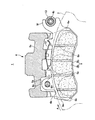
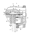
- FIG. 4 is a sectional view taken along the line II in FIG. 3.
- FIG. 4 is a sectional view taken along the line II-II in FIG. 3.
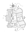
- 1 is a side view of a vehicle disc brake showing an embodiment of the present invention.
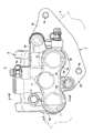
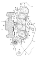
- FIG. 7 is a sectional view taken along line IV-IV in FIG. 6. It is a top view of the disc brake for vehicles which shows one example of the present invention. It is a front view of the disk brake for vehicles similarly.
- FIG. 6 is an explanatory diagram of a state in which when the friction pad on the action part side is removed, the slide pin is pulled out and the friction pad is rotated. It is explanatory drawing at the time of extracting the friction pad of an action part side. It is explanatory drawing at the time of removing the friction pad by the side of a reaction part.
- FIGS. 1 to 9 are views showing one embodiment of the disk brake for a vehicle according to the present invention.
- An arrow A indicates a rotation direction of a disk rotor that rotates integrally with a wheel when the vehicle moves forward.
- the disk entry side is assumed to be when the vehicle is moving forward.
- the vehicle disc brake 1 of the present embodiment includes a disc rotor 2 that rotates integrally with a wheel (not shown) during vehicle travel, a caliper bracket 3 that is attached to a vehicle body at one side of the disc rotor 2, and the caliper bracket 3
- a pin slide-type caliper body 6 supported so as to be slidable in the disk axial direction via a pair of slide pins 4 and 5, and a hanger pin spanned between the action portion 6a and the reaction portion 6b of the caliper body 6 7 and a pair of friction pads 8 and 9 that are suspended by the hanger pins 7 and arranged to face each other with the disc rotor 2 interposed therebetween.
- the caliper body 6 includes the above-described action part 6a and reaction part 6b arranged on both sides of the disk rotor 2, and a bridge part 6c that connects these parts across the outer periphery of the disk rotor 2, and the bridge part 6c.
- the pad spring 10 is contracted between the friction pads 8 and 9.
- the action portion 6a is provided with three bottomed cylinder holes 6d that open on the disk rotor 2 side, and the reaction portion 6b is integrally formed with four reaction force claws 6e.
- a piston 11 is inserted in each cylinder hole 6d in a liquid-tight manner, and a hydraulic pressure chamber 12 is defined between the piston 11 and the bottom of the cylinder hole 6d.
- a female screw portion 6f for attaching the hanger pin 7 is formed on the disk insertion side of the action portion 6a, and a pin insertion portion 6g for inserting the hanger pin 7 is formed coaxially on the disk insertion side of the reaction portion.
- the female screw portion 6f has a large-diameter female screw hole 6h formed on the side opposite to the disk rotor and a first shaft portion insertion hole formed on the disk rotor side and having a smaller diameter than the female screw hole 6h and passing through the shaft portion of the hanger pin 7. 6i, and a conical step portion is formed between the female screw hole 6h and the first shaft portion insertion hole 6i.
- the pin insertion portion 6g is formed on the disk rotor side, communicates with the second shaft portion insertion hole 6j through which the shaft portion 7a of the hanger pin 7 is inserted, and the second shaft portion insertion hole 6j.
- a small-diameter hole 6k formed to have a smaller diameter than the insertion hole 6j and a large-diameter hole 6m that is continuous with the small-diameter hole 6k and that opens to the opposite disk rotor side are provided. It is formed in a mortar shape that gradually becomes larger in diameter.
- the action portion 6a has a first vehicle body mounting arm 6n projecting from the disk delivery side and a second vehicle body mounting arm 6p projecting radially inward from the disk, and the one slide pin 4 is inserted into the first vehicle body mounting arm 6n.
- One slide pin 4 has a threaded portion fitted to the first slide pin mounting arm 3 a of the caliper bracket 3, and the flange portion 4 a of the slide pin 4 is brought into contact with one side surface of the caliper bracket 3, so that A cylindrical torque receiving pin 13 (a torque receiving portion of the present invention) is screwed into the screw portion 4b protruding to the side surface side.
- the torque receiving pin 13 is disposed in the reaction portion direction across the outer periphery of the disc rotor 2 in the disc axial direction on the disc delivery side of the bridge portion 6c.
- the other slide pin 5 is mounted on the second slide pin mounting arm 3b of the caliper bracket 3 so as to protrude in the direction opposite to the disk rotor, and the tip side is inserted into the second vehicle body mounting arm 6p.
- An accommodating recess 6q is formed on the side of the disc rotor on the side of the disc rotor of the bridge portion 6c to accommodate the pad suspension portions 8a, 9a provided on the friction pads 8, 9 so as to be movable in the disc axial direction. Yes.
- the friction pads 8 and 9 are configured by fixing linings 8b and 9b slidably in contact with the side surfaces of the disk rotor 2 to metal back plates 8c and 9c, and on the disk entrance side of the back plates 8c and 9c, In addition, the pad suspension portions 8a and 9a protrude from the outer side in the radial direction of the disk. Hanger pin insertion holes 8d and 9d are formed in the pad suspension portions 8a and 9a, respectively. Further, on the outer surface of the back plate 8c, 9c on the disk insertion side, when the friction pads 8, 9 are assembled to the caliper body 6, knobs 8e, 9e projecting outward from the caliper body 6 are respectively provided. Is formed.
- An ear piece 8f to be supported by the caliper bracket 3 protrudes from the disk return side of the back plate 8c of the friction pad 8 on the working side, and a braking torque is applied to the disk return side of the back plate 8c during braking.
- a torque transmission surface 8g (a torque transmission portion of the present invention) to be transmitted to the bracket 3 is formed. Further, as shown in FIG. 7, the friction pad 8 on the working portion side is opened from the opening end portion P1 on the disk insertion side of the housing recess 6q when the disk insertion side is rotated inward in the disk radial direction.
- the second slide pin mounting arm 3b is formed in a shape that can pass through the space E1 formed between the distal ends P2.
- a bifurcated torque transmission arm 9f (torque transmission portion of the present invention) having an opening on the disk delivery side is formed on the disk delivery side of the back plate 9c of the friction pad 9 on the reaction part side. 9 f is in contact with the torque receiving pin 13.
- the caliper bracket 3 is formed by pressing a single plate material.
- the caliper bracket 3 protrudes outward in the radial direction of the disk on the disk delivery side, and on the inner side of the disk in the radial direction of the disk.
- the projecting second slide pin mounting arm 3b is provided.
- the first slide pin mounting arm 3a is formed with a slide pin mounting hole for mounting the slide pin 4 on the outer peripheral side of the disk, and one body mounting bolt on the disk delivery side with respect to the slide pin mounting hole. Is formed with a bolt hole 3c (an attachment portion of the present invention).
- a torque receiving surface 3d (torque receiving portion of the present invention) that receives torque from the friction pad 8 on the action portion side during braking, and a friction pad on the action portion side
- a support portion 3e that supports the ear piece 8f formed on the base plate 8 is formed orthogonally.
- the second slide pin mounting arm 3b is formed with a slide pin mounting hole 3f for fixing the other slide pin 5, and the other vehicle body mounting bolt is mounted on the inner peripheral side of the disk with respect to the slide pin mounting hole 3f.
- Bolt hole 3g (attachment portion of the present invention) is formed.
- the hanger pin 7 includes a male screw portion 7b having a diameter larger than that of the shaft portion on one end side of the shaft portion 7a and a small diameter shaft portion 7c having a diameter smaller than that of the shaft portion 7a on the other end side. Between 7a, the cone part which becomes a small diameter gradually from the external thread part 7b toward the axial part is formed.
- the small-diameter shaft portion 7c is provided with a circumferential groove 7d for fitting the retaining member 14 on the other end side, and on the other end side of the circumferential groove 7d is a conical shape that gradually becomes smaller in diameter toward the end portion.
- the head 7e is formed.
- the retaining member 14 is formed in a C shape with a resin such as polypropylene, for example, and has an outer diameter slightly larger than the inner diameter of the small-diameter hole 6k.
- the friction pads 8 and 9 are assembled to the caliper bracket 3 and the caliper body 6 formed in this way, the ear piece 8f of the friction pad 8 of the action portion is supported by the support portion 3e, and the torque of the caliper bracket 3 is set.
- the receiving surface 3d is brought into contact with the torque transmission surface 8g of the friction pad 8.
- the friction transmitting pad 9 is supported by bringing the torque transmitting arm 9 f of the friction pad 9 on the reaction portion side into contact with the torque receiving pin 13.
- the pad suspending portions 8a and 9a of the friction pads 8 and 9 are accommodated in the accommodating recess 6q of the bridge portion 6c, and the hanger pin insertion holes 8d and 9d and the female screw portion 6f of the caliper body 6 and the pin are inserted.
- the part 6g is disposed at a position where the axes coincide.
- the hanger pin 7 in a state in which the retaining member 14 is fitted in the circumferential groove 7d, the female screw hole 6h, the first shaft portion insertion hole 6i, the hanger pin insertion holes 8d and 9d, the second shaft portion insertion hole 6j, the small diameter
- the male screw portion 7b is threaded into the female screw hole 6h in order through the hole 6k, and a step formed between the female screw hole 6h and the first shaft portion insertion hole 6i is connected to the male screw portion 7b and the shaft portion 7a. It is made to contact
- the retaining member 14 passes through the small-diameter hole 6k in a compressed state and is disposed in the large-diameter hole 6m.
- the head 7e protrudes outward from the large-diameter hole 6m, and is smaller than the small-diameter hole 6k and the small-diameter hole 6k.
- the hanger pin 7 is prevented from being removed by the retaining member 14 having a slightly larger diameter.
- the friction pads 8 and 9 When the friction pads 8 and 9 are replaced, when the friction pads 8 and 9 are removed from the caliper body 6, the male threaded portion 7 b of the hanger pin 7 is loosened and the retaining member 14 is compressed while the diameter of the hanger pin 7 is reduced. It is extracted from the hole 6k, the second shaft portion insertion hole 6j, the hanger pin insertion holes 8d and 9d, the first shaft portion insertion hole 6i, and the female screw hole 6h.
- the friction pad 8 on the action part side has a knob 8e and rotates the disk insertion side of the friction pad 8 inward in the disk radial direction, as shown in FIG.
- the ear piece 8f leaves the support portion 3e by pulling toward the disk entry side, the disk radial outer side of the back plate 8c passes through the opening end P1, and the disk radial inner side of the back plate 8c is the tip.
- the friction pad 8 can be taken out of the caliper body 6 from the space E1 through the portion P2. Also, the new friction pad 8 to be replaced can be easily inserted into a predetermined place via the space E1.
- the friction pad 9 of the reaction part has a knob 9e and pulls the friction pad 9 toward the disk insertion side while rotating the disk insertion side of the friction pad 9 inward in the disk radial direction.
- the torque transmitting arm 9f is separated from the torque receiving pin 13 and can be taken out of the caliper body 6 through the gap between the reaction force claw 6e and the disc rotor 2.
- the new friction pad 9 to be replaced can be easily inserted into a predetermined place through the gap between the reaction force claw 6e and the disc rotor 2.
- the friction pads 8 and 9 are arranged on the disk insertion side and the pad hanging portions 8a and 9a formed on the outer side in the radial direction of the disk. Since the caliper body 6 and the friction pads 8 and 9 are assembled to the caliper bracket 3 while the caliper body 6 is miniaturized, the hanger pins 7 are removed and the friction pads 8 and 9 are removed. Can be exchanged. Further, since the tabs 8e and 9e projecting outward from the caliper body 6 are formed on the outer surfaces of the friction pads 8 and 9 on the disk insertion side, the tabs 8e and 9e are picked and the friction pad 8 is picked. 9 can be performed satisfactorily. Further, by removing the hanger pin 7 and rotating the friction pad 8, the friction pad 8 can be easily attached / detached via the space E 1, so that the friction pad on the working portion side where the caliper bracket 3 is disposed is provided. 8 can also be easily replaced.
- the present invention is not limited to the above-described embodiments, and the brake torque from the friction pad may be received by the caliper body.
- the shape of the part is arbitrary.
- the hanger pin is not limited to the present embodiment, and the retaining structure is arbitrary as long as it can be attached and detached, and is not limited to the one using a C-shaped retaining member.
- the number of pistons is not limited to this embodiment, and is arbitrary.
Landscapes
- Engineering & Computer Science (AREA)
- General Engineering & Computer Science (AREA)
- Mechanical Engineering (AREA)
- Braking Arrangements (AREA)
Abstract
Description
Claims (3)
- ディスクロータの一側部に配置され、ピストンを備えた作用部と、前記ディスクロータの他側部に配置され、反力爪を備えた反作用部とをブリッジ部で連結してキャリパボディを形成し、該キャリパボディを、前記ディスクロータの一側部で車体に固設されるキャリパブラケットに一対のスライドピンを介してディスク軸方向にスライド可能に支持し、前記作用部と反作用部との間に前記ディスクロータを挟んで一対の摩擦パッドを対向配置し、該摩擦パッドに設けた吊下げ部を、前記作用部と反作用部とに亘ってディスク軸方向に架け渡されるハンガーピンに吊持させた車両用ディスクブレーキにおいて、
前記摩擦パッドは、車両前進時におけるディスク回入側で、且つ、ディスク半径方向外側に前記パッド吊下げ部が形成されるとともに、ディスク回出側に、前記キャリパボディ又は前記キャリパブラケットのいずれか一方に設けたトルク受部に当接して制動トルクを伝達させるトルク伝達部を備え、
前記キャリパボディは、前記ブリッジ部のディスクロータ側面に、前記パッド吊下げ部をディスク軸方向に移動可能に収容する収容凹部が形成されていることを特徴とする車両用ディスクブレーキ。 - 前記摩擦パッドはディスク回入側の外面に、前記キャリパボディよりも外方に突出する摘まみ片を備えていることを特徴とする請求項1記載の車両用ディスクブレーキ。
- 前記摩擦パッドは、前記ハンガーピンを前記キャリパボディから取り外し、前記摩擦パッドのディスク回入側をディスク半径方向内側に回動させることにより、前記キャリパボディを前記キャリパブラケットに組み付けた状態で、前記キャリパボディから取り外し可能となることを特徴とする請求項1又は2記載の車両用ディスクブレーキ。
Priority Applications (3)
| Application Number | Priority Date | Filing Date | Title |
|---|---|---|---|
| CN201680034283.9A CN107636341B (zh) | 2015-06-12 | 2016-06-10 | 车辆用盘式制动器 |
| JP2017523707A JP6594976B2 (ja) | 2015-06-12 | 2016-06-10 | 車両用ディスクブレーキ |
| BR112017023510-2A BR112017023510B1 (pt) | 2015-06-12 | 2016-06-10 | Freio a disco veicular |
Applications Claiming Priority (2)
| Application Number | Priority Date | Filing Date | Title |
|---|---|---|---|
| JP2015118833 | 2015-06-12 | ||
| JP2015-118833 | 2015-06-12 |
Publications (1)
| Publication Number | Publication Date |
|---|---|
| WO2016199880A1 true WO2016199880A1 (ja) | 2016-12-15 |
Family
ID=57503413
Family Applications (1)
| Application Number | Title | Priority Date | Filing Date |
|---|---|---|---|
| PCT/JP2016/067310 Ceased WO2016199880A1 (ja) | 2015-06-12 | 2016-06-10 | 車両用ディスクブレーキ |
Country Status (5)
| Country | Link |
|---|---|
| JP (1) | JP6594976B2 (ja) |
| CN (1) | CN107636341B (ja) |
| BR (1) | BR112017023510B1 (ja) |
| TW (1) | TWI679356B (ja) |
| WO (1) | WO2016199880A1 (ja) |
Cited By (3)
| Publication number | Priority date | Publication date | Assignee | Title |
|---|---|---|---|---|
| CN108626273A (zh) * | 2017-03-23 | 2018-10-09 | 株式会社万都 | 用于车辆的盘式制动器 |
| WO2020066487A1 (ja) * | 2018-09-26 | 2020-04-02 | 本田技研工業株式会社 | ディスクブレーキ |
| US20210088090A1 (en) * | 2018-06-15 | 2021-03-25 | Nissin Kogyo Co., Ltd. | Vehicular disc brake |
Families Citing this family (1)
| Publication number | Priority date | Publication date | Assignee | Title |
|---|---|---|---|---|
| JP7675312B2 (ja) * | 2020-03-30 | 2025-05-14 | Astemo株式会社 | 車両用ディスクブレーキのキャリパボディ取付け構造 |
Citations (5)
| Publication number | Priority date | Publication date | Assignee | Title |
|---|---|---|---|---|
| JPH1182569A (ja) * | 1997-09-12 | 1999-03-26 | Nissin Kogyo Kk | 車両用ディスクブレーキ |
| JPH11108086A (ja) * | 1997-10-07 | 1999-04-20 | Nissin Kogyo Kk | 車両用ディスクブレーキ |
| JP2004132449A (ja) * | 2002-10-10 | 2004-04-30 | Nissin Kogyo Co Ltd | 車両用ディスクブレーキ |
| JP2009257514A (ja) * | 2008-04-18 | 2009-11-05 | Nissin Kogyo Co Ltd | 車両用ディスクブレーキ |
| JP2013190035A (ja) * | 2012-03-14 | 2013-09-26 | Nissin Kogyo Co Ltd | 車両用ディスクブレーキ |
Family Cites Families (11)
| Publication number | Priority date | Publication date | Assignee | Title |
|---|---|---|---|---|
| JPS6230588Y2 (ja) * | 1981-02-25 | 1987-08-06 | ||
| JPH032012Y2 (ja) * | 1986-10-08 | 1991-01-21 | ||
| JPS63146232U (ja) * | 1987-03-18 | 1988-09-27 | ||
| FR2660380B1 (fr) * | 1990-03-29 | 1992-06-12 | Bendix Europ Services Tech | Frein a disque a chambre de travail thermiquement isolee. |
| AUPQ547000A0 (en) * | 2000-02-07 | 2000-03-02 | Pbr Australia Pty Ltd | Disc brake assembly |
| EP1597492B1 (en) * | 2003-02-28 | 2017-03-22 | Freni Brembo S.p.A. | Pad and caliper of a disk brake |
| JP4494960B2 (ja) * | 2004-02-27 | 2010-06-30 | 日立オートモティブシステムズ株式会社 | ディスクブレーキ |
| DE102005001482A1 (de) * | 2005-01-12 | 2006-07-20 | Gustav Magenwirth Gmbh & Co. Kg | Bremszange und Bremsbelag für eine Bremszange |
| CN2816476Y (zh) * | 2005-07-27 | 2006-09-13 | 南京长安汽车有限公司 | 悬浮钳式盘制动器 |
| DE102007049981B4 (de) * | 2007-10-18 | 2009-07-30 | Knorr-Bremse Systeme für Nutzfahrzeuge GmbH | Bremsbelag einer Scheibenbremse |
| JP6182435B2 (ja) * | 2013-11-15 | 2017-08-16 | 日信工業株式会社 | 車両用ディスクブレーキ |
-
2016
- 2016-06-07 TW TW105117961A patent/TWI679356B/zh active
- 2016-06-10 BR BR112017023510-2A patent/BR112017023510B1/pt active IP Right Grant
- 2016-06-10 WO PCT/JP2016/067310 patent/WO2016199880A1/ja not_active Ceased
- 2016-06-10 JP JP2017523707A patent/JP6594976B2/ja active Active
- 2016-06-10 CN CN201680034283.9A patent/CN107636341B/zh active Active
Patent Citations (5)
| Publication number | Priority date | Publication date | Assignee | Title |
|---|---|---|---|---|
| JPH1182569A (ja) * | 1997-09-12 | 1999-03-26 | Nissin Kogyo Kk | 車両用ディスクブレーキ |
| JPH11108086A (ja) * | 1997-10-07 | 1999-04-20 | Nissin Kogyo Kk | 車両用ディスクブレーキ |
| JP2004132449A (ja) * | 2002-10-10 | 2004-04-30 | Nissin Kogyo Co Ltd | 車両用ディスクブレーキ |
| JP2009257514A (ja) * | 2008-04-18 | 2009-11-05 | Nissin Kogyo Co Ltd | 車両用ディスクブレーキ |
| JP2013190035A (ja) * | 2012-03-14 | 2013-09-26 | Nissin Kogyo Co Ltd | 車両用ディスクブレーキ |
Cited By (9)
| Publication number | Priority date | Publication date | Assignee | Title |
|---|---|---|---|---|
| CN108626273A (zh) * | 2017-03-23 | 2018-10-09 | 株式会社万都 | 用于车辆的盘式制动器 |
| US20210088090A1 (en) * | 2018-06-15 | 2021-03-25 | Nissin Kogyo Co., Ltd. | Vehicular disc brake |
| JPWO2019240117A1 (ja) * | 2018-06-15 | 2021-06-24 | 日立Astemo株式会社 | 車両用ディスクブレーキ |
| JP7308824B2 (ja) | 2018-06-15 | 2023-07-14 | 日立Astemo株式会社 | 車両用ディスクブレーキ |
| US12066066B2 (en) * | 2018-06-15 | 2024-08-20 | Hitachi Astemo, Ltd. | Vehicular disc brake |
| EP3809009B1 (en) | 2018-06-15 | 2024-10-30 | Hitachi Astemo, Ltd. | Vehicular disc brake |
| WO2020066487A1 (ja) * | 2018-09-26 | 2020-04-02 | 本田技研工業株式会社 | ディスクブレーキ |
| JPWO2020066487A1 (ja) * | 2018-09-26 | 2021-08-30 | 本田技研工業株式会社 | ディスクブレーキ |
| JP7023378B2 (ja) | 2018-09-26 | 2022-02-21 | 本田技研工業株式会社 | ディスクブレーキ |
Also Published As
| Publication number | Publication date |
|---|---|
| TWI679356B (zh) | 2019-12-11 |
| BR112017023510A2 (pt) | 2019-05-14 |
| CN107636341A (zh) | 2018-01-26 |
| BR112017023510B1 (pt) | 2022-12-13 |
| JP6594976B2 (ja) | 2019-10-23 |
| TW201704655A (zh) | 2017-02-01 |
| CN107636341B (zh) | 2020-07-17 |
| JPWO2016199880A1 (ja) | 2018-03-29 |
Similar Documents
| Publication | Publication Date | Title |
|---|---|---|
| JP6594976B2 (ja) | 車両用ディスクブレーキ | |
| US12066066B2 (en) | Vehicular disc brake | |
| JP4741693B2 (ja) | 化粧プレートの取付構造 | |
| CN101852256B (zh) | 盘式制动设备 | |
| JP5726151B2 (ja) | 車両用ディスクブレーキ | |
| CN103912608A (zh) | 采用摩擦片三爪弹簧结构的盘式制动器 | |
| WO2014175388A1 (ja) | ディスクブレーキ装置 | |
| JP2012072830A (ja) | ディスクブレーキのパッド戻し機構 | |
| JP2012202528A (ja) | 車両用ディスクブレーキ | |
| JP2015152034A (ja) | 車両用ディスクブレーキ | |
| JP2015007439A (ja) | 車両用ディスクブレーキ | |
| JP2012036979A (ja) | 車両用ディスクブレーキ | |
| JP2016017558A (ja) | ディスクブレーキ装置 | |
| JP5587876B2 (ja) | 車両用ディスクブレーキのキャリパボディ支持構造 | |
| TWI664362B (zh) | Disc brake | |
| JP4979670B2 (ja) | ディスクブレーキ装置 | |
| JP5436387B2 (ja) | 車両用ディスクブレーキ | |
| JP5603797B2 (ja) | 車両用ディスクブレーキ | |
| JP4590427B2 (ja) | ピンスライド型車両用ディスクブレーキ | |
| JP2013190035A (ja) | 車両用ディスクブレーキ | |
| JP4839272B2 (ja) | ピンスライド型車両用ディスクブレーキ | |
| JP2020159368A (ja) | 車両用ディスクブレーキ | |
| JP2000249173A (ja) | 車両用ディスクブレーキのハンガーピン抜け止め構造 | |
| JP5562294B2 (ja) | 車両用ディスクブレーキ | |
| JP2010185503A (ja) | 車両用ディスクブレーキのキャリパボディ |
Legal Events
| Date | Code | Title | Description |
|---|---|---|---|
| 121 | Ep: the epo has been informed by wipo that ep was designated in this application |
Ref document number: 16807585 Country of ref document: EP Kind code of ref document: A1 |
|
| ENP | Entry into the national phase |
Ref document number: 2017523707 Country of ref document: JP Kind code of ref document: A |
|
| NENP | Non-entry into the national phase |
Ref country code: DE |
|
| REG | Reference to national code |
Ref country code: BR Ref legal event code: B01A Ref document number: 112017023510 Country of ref document: BR |
|
| 32PN | Ep: public notification in the ep bulletin as address of the adressee cannot be established |
Free format text: NOTING OF LOSS OF RIGHTS PURSUANT TO RULE 112(1) EPC (EPO FORM 1205 DATED 14.03.2018) |
|
| 122 | Ep: pct application non-entry in european phase |
Ref document number: 16807585 Country of ref document: EP Kind code of ref document: A1 |
|
| ENP | Entry into the national phase |
Ref document number: 112017023510 Country of ref document: BR Kind code of ref document: A2 Effective date: 20171031 |
|
| WWG | Wipo information: grant in national office |
Ref document number: 202118057051 Country of ref document: IN |