WO2016199852A1 - 表面処理鋼板 - Google Patents
表面処理鋼板 Download PDFInfo
- Publication number
- WO2016199852A1 WO2016199852A1 PCT/JP2016/067213 JP2016067213W WO2016199852A1 WO 2016199852 A1 WO2016199852 A1 WO 2016199852A1 JP 2016067213 W JP2016067213 W JP 2016067213W WO 2016199852 A1 WO2016199852 A1 WO 2016199852A1
- Authority
- WO
- WIPO (PCT)
- Prior art keywords
- plating layer
- vanadium
- steel plate
- layer
- plating
- Prior art date
- Legal status (The legal status is an assumption and is not a legal conclusion. Google has not performed a legal analysis and makes no representation as to the accuracy of the status listed.)
- Ceased
Links
Images





Classifications
-
- C—CHEMISTRY; METALLURGY
- C25—ELECTROLYTIC OR ELECTROPHORETIC PROCESSES; APPARATUS THEREFOR
- C25D—PROCESSES FOR THE ELECTROLYTIC OR ELECTROPHORETIC PRODUCTION OF COATINGS; ELECTROFORMING; APPARATUS THEREFOR
- C25D5/00—Electroplating characterised by the process; Pretreatment or after-treatment of workpieces
- C25D5/60—Electroplating characterised by the structure or texture of the layers
- C25D5/615—Microstructure of the layers, e.g. mixed structure
- C25D5/619—Amorphous layers
-
- C—CHEMISTRY; METALLURGY
- C25—ELECTROLYTIC OR ELECTROPHORETIC PROCESSES; APPARATUS THEREFOR
- C25D—PROCESSES FOR THE ELECTROLYTIC OR ELECTROPHORETIC PRODUCTION OF COATINGS; ELECTROFORMING; APPARATUS THEREFOR
- C25D5/00—Electroplating characterised by the process; Pretreatment or after-treatment of workpieces
- C25D5/34—Pretreatment of metallic surfaces to be electroplated
- C25D5/36—Pretreatment of metallic surfaces to be electroplated of iron or steel
-
- C—CHEMISTRY; METALLURGY
- C25—ELECTROLYTIC OR ELECTROPHORETIC PROCESSES; APPARATUS THEREFOR
- C25D—PROCESSES FOR THE ELECTROLYTIC OR ELECTROPHORETIC PRODUCTION OF COATINGS; ELECTROFORMING; APPARATUS THEREFOR
- C25D3/00—Electroplating: Baths therefor
- C25D3/02—Electroplating: Baths therefor from solutions
- C25D3/12—Electroplating: Baths therefor from solutions of nickel or cobalt
-
- C—CHEMISTRY; METALLURGY
- C25—ELECTROLYTIC OR ELECTROPHORETIC PROCESSES; APPARATUS THEREFOR
- C25D—PROCESSES FOR THE ELECTROLYTIC OR ELECTROPHORETIC PRODUCTION OF COATINGS; ELECTROFORMING; APPARATUS THEREFOR
- C25D3/00—Electroplating: Baths therefor
- C25D3/02—Electroplating: Baths therefor from solutions
- C25D3/22—Electroplating: Baths therefor from solutions of zinc
-
- C—CHEMISTRY; METALLURGY
- C25—ELECTROLYTIC OR ELECTROPHORETIC PROCESSES; APPARATUS THEREFOR
- C25D—PROCESSES FOR THE ELECTROLYTIC OR ELECTROPHORETIC PRODUCTION OF COATINGS; ELECTROFORMING; APPARATUS THEREFOR
- C25D5/00—Electroplating characterised by the process; Pretreatment or after-treatment of workpieces
- C25D5/10—Electroplating with more than one layer of the same or of different metals
- C25D5/12—Electroplating with more than one layer of the same or of different metals at least one layer being of nickel or chromium
-
- C—CHEMISTRY; METALLURGY
- C25—ELECTROLYTIC OR ELECTROPHORETIC PROCESSES; APPARATUS THEREFOR
- C25D—PROCESSES FOR THE ELECTROLYTIC OR ELECTROPHORETIC PRODUCTION OF COATINGS; ELECTROFORMING; APPARATUS THEREFOR
- C25D5/00—Electroplating characterised by the process; Pretreatment or after-treatment of workpieces
- C25D5/60—Electroplating characterised by the structure or texture of the layers
-
- C—CHEMISTRY; METALLURGY
- C25—ELECTROLYTIC OR ELECTROPHORETIC PROCESSES; APPARATUS THEREFOR
- C25D—PROCESSES FOR THE ELECTROLYTIC OR ELECTROPHORETIC PRODUCTION OF COATINGS; ELECTROFORMING; APPARATUS THEREFOR
- C25D5/00—Electroplating characterised by the process; Pretreatment or after-treatment of workpieces
- C25D5/60—Electroplating characterised by the structure or texture of the layers
- C25D5/605—Surface topography of the layers, e.g. rough, dendritic or nodular layers
-
- C—CHEMISTRY; METALLURGY
- C25—ELECTROLYTIC OR ELECTROPHORETIC PROCESSES; APPARATUS THEREFOR
- C25D—PROCESSES FOR THE ELECTROLYTIC OR ELECTROPHORETIC PRODUCTION OF COATINGS; ELECTROFORMING; APPARATUS THEREFOR
- C25D5/00—Electroplating characterised by the process; Pretreatment or after-treatment of workpieces
- C25D5/60—Electroplating characterised by the structure or texture of the layers
- C25D5/615—Microstructure of the layers, e.g. mixed structure
- C25D5/617—Crystalline layers
-
- C—CHEMISTRY; METALLURGY
- C25—ELECTROLYTIC OR ELECTROPHORETIC PROCESSES; APPARATUS THEREFOR
- C25D—PROCESSES FOR THE ELECTROLYTIC OR ELECTROPHORETIC PRODUCTION OF COATINGS; ELECTROFORMING; APPARATUS THEREFOR
- C25D7/00—Electroplating characterised by the article coated
- C25D7/06—Wires; Strips; Foils
- C25D7/0614—Strips or foils
- C25D7/0621—In horizontal cells
-
- C—CHEMISTRY; METALLURGY
- C25—ELECTROLYTIC OR ELECTROPHORETIC PROCESSES; APPARATUS THEREFOR
- C25D—PROCESSES FOR THE ELECTROLYTIC OR ELECTROPHORETIC PRODUCTION OF COATINGS; ELECTROFORMING; APPARATUS THEREFOR
- C25D9/00—Electrolytic coating other than with metals
- C25D9/04—Electrolytic coating other than with metals with inorganic materials
- C25D9/08—Electrolytic coating other than with metals with inorganic materials by cathodic processes
- C25D9/10—Electrolytic coating other than with metals with inorganic materials by cathodic processes on iron or steel
-
- C—CHEMISTRY; METALLURGY
- C25—ELECTROLYTIC OR ELECTROPHORETIC PROCESSES; APPARATUS THEREFOR
- C25D—PROCESSES FOR THE ELECTROLYTIC OR ELECTROPHORETIC PRODUCTION OF COATINGS; ELECTROFORMING; APPARATUS THEREFOR
- C25D5/00—Electroplating characterised by the process; Pretreatment or after-treatment of workpieces
- C25D5/48—After-treatment of electroplated surfaces
Definitions
- the present invention relates to a surface-treated steel sheet excellent in corrosion resistance (barrier property) of a plating in a corrosive environment and coating film adhesion.
- electrogalvanized steel sheets have been used in various fields such as home appliances, building materials, and automobiles.
- barrier property corrosion resistance
- the coating weight of the galvanized layer is increased, there is a problem that the manufacturing cost increases and the workability and the weldability decrease.
- the technique of forming a coating film on the surface is used widely conventionally as a method of improving the barrier property and appearance of an electrogalvanized steel plate.
- the adhesion coating film adhesion
- the effect of forming the coating film is sufficient. I can not get it. For this reason, while improving the barrier property of an electrogalvanized steel plate, it is required to improve coating-film adhesiveness.
- Non-Patent Documents 1 to 4 describe a technique of subjecting a Zn-V oxide to complex electrodeposition on the surface of a copper plate which is a cathode.
- Patent Document 1 describes a technique for forming a V-enriched layer in a surface layer portion of a plated layer of a zinc-based plated steel sheet.
- Patent Document 2 describes a technology related to a plating layer containing zinc and vanadium and having a plurality of dendritic arms.
- Patent Document 3 describes that a zinc- and vanadium-containing plating layer formed on a steel plate has a dendritic crystal in which vanadium oxide is present in zinc, and portions other than dendritic crystal are described. It is described that a phase having a higher vanadium content than in a dendritic crystal is present.
- Patent Document 4 describes that in a zinc-based composite electroplated steel sheet containing zinc and vanadium hydroxide, vanadium hydroxide is co-deposited in zinc.
- the present inventor repeated earnest examination, as shown below. That is, the present inventor formed a plating layer containing zinc and vanadium or zirconium on the surface of a steel plate by electroplating under various conditions using the steel plate as a cathode, and investigated its barrier properties and coating adhesion. .
- the plating layer containing zinc and vanadium has a dendritic crystal containing metallic zinc and an intercrystalline filling region containing hydrated vanadium oxide or vanadium hydroxide. I found that it would be better to form a layer.
- a plated layer has an intercrystalline filling region containing hydrated vanadium oxide or vanadium hydroxide, and therefore, for example, a plated steel plate provided with a zinc plated layer in place of the plated layer.
- the corrosion potential is noble, and has excellent barrier properties.
- the inventor also found that under certain conditions, a phase containing hydrated zirconia oxide or zirconia hydroxide is formed around dendritic crystals consisting of metallic zinc. It has been found that such a plated layer has a barrier property equal to or higher than that of zinc vanadium plating and is excellent in coating film adhesion, and the present invention has been completed.
- Each aspect of the present invention is as follows.
- a surface-treated steel plate comprises: a steel plate; and a plating layer formed on one side or both sides of the steel plate and containing zinc and vanadium or zirconium; And an inter-crystal filling region that shows an amorphous diffraction pattern when filling between the dendrite-like crystals and performing electron beam diffraction; and the plating layer contains the vanadium.
- the intercrystalline filling region comprises hydrated vanadium oxide or vanadium hydroxide
- the plating layer comprises zirconium
- the intercrystalline filling region is hydrated zirconium oxide or zirconium water Contains oxides.
- the plating layer contains the vanadium, V / Zn, which is a molar ratio of the vanadium to the zinc in the intercrystalline filling region, is 0 .10 or more and 2.00 or less, and when the plating layer contains the zirconium, Zr / Zn which is a molar ratio of the zirconium and the zinc in the inter-crystal filling region is 1.00 or more. You may employ
- the plating layer contains the vanadium, and the surface layer of the dendritic crystal contains zinc oxide or zinc hydroxide. A configuration may be adopted.
- Zn / V which is a molar ratio between zinc and the vanadium, is 8 between the steel sheet and the plating layer. You may employ
- an organic resin film having a polyurethane resin and 1 to 20% by mass of carbon black on the surface of the plating layer A configuration further provided may be adopted.
- the method for producing a surface-treated steel sheet according to an aspect of the present invention is a method for producing a surface-treated steel sheet according to any one of the above (1) to (5), 0 to 18 A / dm using a plating bath containing 0.000 mol / l of Zn 2+ ion and 0.01 to 2.00 mol / l of V ion or 0.10 to 4.00 mol / l of Zr ion
- the surface-treated steel plate which has the outstanding barrier property and coating-film adhesiveness can be provided.
- FIG. 5A It is a schematic diagram for demonstrating generation
- TEM transmission electron microscope
- SEM scanning electron microscope
- FIG. 1 is a cross-sectional schematic diagram for demonstrating an example of the surface-treated steel plate 10 which concerns on this embodiment.
- an underlayer 20, a plating layer 30, and a surface layer 40 are formed in this order from the side of the steel plate 1 on both sides of the steel plate 1.
- FIG. 1 only the foundation layer 20, the plating layer 30, and the surface layer 40 formed on one surface (upper surface) side of the steel plate 1 are described, and the description on the other surface (lower surface) is omitted.
- the steel plate 1 on which the plating layer 30 is formed is not particularly limited.
- the steel plate 1 extremely low C type (ferrite main structure), Al-k type (structure containing pearlite in ferrite), two phase structure type (for example, structure including martensite in ferrite, bainite in ferrite Any type of steel plate may be used, such as a structure including A), a processing induced transformation type (a structure including retained austenite in ferrite), a microcrystalline type (ferrite main structure), and the like.
- an underlayer 20 may be provided between the steel plate 1 and the plating layer 30.
- the foundation layer 20 is provided as necessary in order to improve the adhesion between the steel plate 1 and the plating layer 30.
- the base layer 20 having a thickness of 1 to 300 nm and made of a crystal containing nickel be provided.
- the plating layer 30 is disposed between the dendritic crystal 31 and the dendritic crystal 31 as shown in FIG. 1, and the intercrystalline filling region 32 showing an amorphous diffraction pattern when electron beam diffraction is performed.
- amorphous means that electron beam diffraction is performed for each layer from the cross-sectional direction using a transmission electron microscope (TEM), and a diffraction pattern derived from a crystal structure can not be obtained.
- TEM transmission electron microscope
- the intercrystalline packing region 32 comprises hydrated vanadium oxide or vanadium hydroxide.
- the inter-crystal filling region 32 preferably contains vanadium hydroxide in order to improve coating film adhesion.
- the intercrystalline filling region 32 contains zinc. The inclusion of zinc in the intercrystalline filling region 32 improves the corrosion resistance.
- the molar ratio (V / Zn) of vanadium to zinc in the intercrystalline filling region 32 is at least 0.10. It is preferable that it is 2.00 or less.
- the above-mentioned molar ratio (V / Zn) is in the above-mentioned range, and when the electron beam diffraction is performed, the intercrystalline filling region exhibits an amorphous diffraction pattern, thereby providing excellent corrosion resistance (barrier property) and coating. Film adhesion is obtained.
- a plurality of dendrite crystals 31 are formed in the plating layer 30.
- the shapes of the plurality of dendritic crystals 31 may all be different, or the same one may be included.
- the shape of each dendritic crystal 31 may be needle-like or rod-like.
- each dendritic crystal 31 may extend linearly in the length direction or may extend curvilinearly.
- the cross-sectional shape of each dendritic crystal 31 is not particularly limited, and may be, for example, a circle, an ellipse, or a polygon.
- the cross-sectional shape of each dendritic crystal 31 may be uniform or nonuniform in the longitudinal direction.
- the outer peripheral dimension of each of the dendritic crystals 31 may be uniform or nonuniform in the longitudinal direction.
- each dendritic crystal 31 has an interior 3 a of a dendritic crystal and a surface layer 3 b formed on the surface of the dendritic crystal 31.
- the interior 3a of the dendritic crystal 31 is grown from the steel plate 1 side to the outside, and has a plurality of branched branches.
- the surface layer 3 b is formed to have a substantially uniform thickness so as to cover the surface of the interior 3 a of the dendritic crystal 31.
- the dendritic crystal 31 shown in FIG. 1 having the interior 3a and the surface layer 3b of the dendritic crystal 31 has a maximum length of 4.0 ⁇ m or less and a maximum width of 0.5 ⁇ m or less when viewed in cross section Is preferred.
- the maximum length and the maximum width of the dendritic crystal 31 are in the above range, the dense plated layer 30 having the fine dendritic crystal 31 is obtained. Therefore, the barrier function of the plating layer 30 is improved, and a further excellent barrier property can be obtained.
- the maximum length of the dendritic crystal 31 is more preferably 3.0 ⁇ m or less.
- the maximum width of the cross section of the dendritic crystal 31 is more preferably 0.4 ⁇ m or less.
- the maximum length of the dendritic crystal 31 refers to the cross section of the plating layer observed using a scanning electron microscope (SEM), and the maximum length of 50 dendritic crystals 31 is measured. It is obtained by calculating the average value.
- the maximum width of the cross section of the dendritic crystal 31 refers to the cross section of the plating layer observed using a transmission electron microscope (TEM), and the maximum width of 50 dendritic crystals 31 is measured, It is obtained by calculating the average value.
- the interior 3a of the dendritic crystal 31 contains metallic zinc.
- the interior 3a of the dendritic crystal 31 may contain other metallic components such as nickel which is nobler than the precipitation potential of zinc.
- the surface layer 3 b preferably contains a crystal containing zinc oxide or zinc hydroxide.
- the surface layer 3 b more preferably contains zinc oxide crystals.
- the thickness of the surface layer 3b is preferably 0.1 to 500 nm.
- the granular crystal 3 c may be contained in the interior 3 a of the dendritic crystal 31.
- the granular crystals 3c contain zinc and nickel.
- the particle diameter of the granular crystals 3c is preferably 0.1 to 500 nm. When the particle diameter of the granular crystals 3c is in the above range, better coating film adhesion can be obtained.
- Zn / V which is a molar ratio of zinc and vanadium contained in the plating layer 30 is 0.50 or more and less than 8.00.
- Zn / V is 0.50 or more and less than 8.00, an excellent barrier function by containing vanadium is obtained, which is preferable.
- a zinc-containing base plating layer (not between the steel plate 1 and the plating layer 30 (when the base layer 20 is formed, between the base layer 20 and the plating layer 30) ) May be formed. It is because the outstanding corrosion-resistant improvement effect by sacrificial corrosion protection of zinc is acquired by forming a base plating layer (not shown).
- the undercoat layer (not shown) may contain zinc and vanadium, and Zn / V, which is a molar ratio of zinc to vanadium, may be 8.00 or more.
- the base plating layer (not shown) may be made of only zinc.
- an upper plating layer (not shown) containing zinc may be formed in the upper layer of the plating layer 30, an upper plating layer (not shown) containing zinc may be formed.
- the formation of the upper plating layer (not shown) is preferable because an excellent corrosion resistance improvement effect by sacrificial corrosion protection of zinc can be obtained.
- the upper plating layer (not shown) may be made only of zinc. Further, the upper plating layer (not shown) may contain zinc and vanadium, and Zn / V, which is a molar ratio of the zinc and the vanadium, may be 8.00 or more.
- an undercoating layer (not shown) can be formed.
- the upper plating layer (not shown) can be formed on the plating layer 30 by the same method as the base plating layer (not shown).
- the molar ratio (a / b) of the amount of zinc (a) contained in the interior 3a of the dendritic crystal 31 to the total (b) of the amount of zinc contained in the intercrystalline filling region 32 and the surface layer 3b of the dendritic crystal 31 Is preferably in the range of 0.10 or more and 3.00 or less.
- the above molar ratio (a / b) is set to 0.20 or more.
- said molar ratio (a / b) is 3.00 or less, the steel plate 1 which originates in the zinc oxide or zinc hydroxide contained in the surface layer of the dendritic crystal 31 being hard to let air and water pass.
- the barrier property improving effect of the present invention can be effectively obtained, and more excellent barrier property can be obtained.
- the molar ratio (a / b) is more preferably 0.25 or less.
- the molar ratio of the total (A) of the amount of zinc contained in the dendritic crystal 31 and the amount of zinc contained in the surface layer 3b of the dendritic crystal 31 and the molar ratio (B) of the vanadium contained in the intercrystalline filling region 32 A / B) is preferably 0.05 or more and 6.00 or less.
- the sacrificial anticorrosive action by the metal zinc contained in the dendritic crystal 31 and the zinc oxide or zinc hydroxide contained in the surface layer 3 b of the dendritic crystal 31 The barrier property improving action by the substance is effectively obtained, and the better barrier property is obtained.
- the above molar ratio (A / B) is 0.10 or more More preferable. Moreover, when said molar ratio (A / B) is 6.00 or less, the effect of making the corrosion potential noble by containing vanadium, and improving a barrier property is exhibited more effectively.
- the molar ratio (A / B) is more preferably 5.00 or less, and still more preferably 4.50 or less, in order to further improve the barrier property improving action by containing vanadium.
- the vanadium content contained in the plating layer 30 is preferably 1% by mass to 20% by mass. If the amount of vanadium in the plating layer 30 is 1% by mass or more, better barrier properties can be obtained.
- the vanadium content in the plating layer 30 is more preferably 4% by mass or more in order to further improve the barrier property and the coating film adhesion. When the vanadium content in the plating layer 30 is 20% by mass or less, the contents of the dendritic crystal 31 and the surface layer 3b of the dendritic crystal 31 increase relatively, and the sacrificial corrosion action and dendritic shape by the dendritic crystal 31 The barrier property improving action of the surface layer 3 b of the crystal 31 can be effectively obtained.
- the vanadium content of the plating layer 30 is more preferably 15% by mass or less in order to secure the content of the dendritic crystal 31 and the surface layer 3 b of the dendritic crystal 31.
- the adhesion amount of the plating layer 30 is preferably 1 g / m 2 or more, and preferably 3 g / m 2 or more, in order to improve the barrier property.
- the adhesion amount of the plating layer 30 is preferably 90 g / m 2 or less, more preferably 50 g / m 2 or less, and still more preferably 15 g / m 2 or less.
- the adhesion amount of the plating layer 30 is 15 g / m 2 or less, the amount of metal to be deposited may be smaller than that of conventional electrogalvanization (usually about 20 g / m 2 ), etc. It is economically superior in terms of metal cost and power cost to form
- the surface-treated steel sheet 10 of the present embodiment preferably has a natural immersion potential (corrosion potential) of -0.8 V or more when the plating layer 30 is used as a working electrode and immersed in a 5% NaCl aqueous solution at 25 ° C.
- the above-mentioned corrosion potential is preferably 0.2 V or more (noble) higher than a plated steel plate (about corrosion potential-about 1.0 V) in which a galvanized layer is provided instead of the plating layer 30.
- the above-mentioned corrosion potential is more preferably ⁇ 0.7 V or more.
- a surface layer 40 composed of a film of one or more layers is formed on the surface of the plating layer 30, a surface layer 40 composed of a film of one or more layers is formed.
- the surface layer 40 is provided as needed.
- the formation of the surface layer 40 improves the corrosion resistance.
- the film of one or more layers forming the surface layer 40 preferably contains an organic resin (R).
- the organic resin (R) contained in the film is not particularly limited and, for example, a polyurethane resin can be mentioned.
- a polyurethane resin can be mentioned.
- the organic resin (R) contained in the film one or more organic resins (not modified) may be mixed and used, or at least one organic resin may be used in the presence of at least one organic resin.
- One or two or more organic resins obtained by modifying one other organic resin may be used in combination.
- polyurethane resin used for organic resin (R) after making a polyol compound and a polyisocyanate compound react, what is obtained by chain-extending with a chain extender etc. can be mentioned, for example.
- the polyol compound used as a raw material of the polyurethane resin is not particularly limited as long as it is a compound containing two or more hydroxyl groups per molecule, and examples thereof include ethylene glycol, propylene glycol, diethylene glycol, and 1,6-hexanediol.
- Neopentyl glycol triethylene glycol, glycerin, trimethylol ethane, trimethylol propane, polycarbonate polyol, polyester polyol, polyether polyol such as bisphenol hydroxypropyl ether, polyester amide polyol, acrylic polyol, polyurethane polyol, or mixtures thereof It can be mentioned.
- the compound containing 2 or more of isocyanate groups per molecule is used, for example, aliphatic isocyanate, such as hexamethylene diisocyanate (HDI), isophorone diisocyanate (IPDI) And alicyclic diisocyanates, aromatic diisocyanates such as tolylene diisocyanate (TDI), aromatic aliphatic diisocyanates such as diphenylmethane diisocyanate (MDI), and mixtures thereof.
- aliphatic isocyanate such as hexamethylene diisocyanate (HDI), isophorone diisocyanate (IPDI)
- alicyclic diisocyanates aromatic diisocyanates such as tolylene diisocyanate (TDI), aromatic aliphatic diisocyanates such as diphenylmethane diisocyanate (MDI), and mixtures thereof.
- a compound containing one or more active hydrogens in the molecule is used.
- the polyurethane resin used for the organic resin (R) is a polyol compound contained in the raw material solution by heating the raw material solution containing the blocked isocyanate compound and the above-mentioned polyol compound to a temperature at which the blocking agent dissociates. It may be obtained by reacting with the polyol component of The blocked isocyanate compound regenerates the isocyanate group by heating to a temperature at which the blocking agent dissociates.
- a block isocyanate compound what masked the isocyanate group of the said polyisocyanate compound by the conventionally well-known block agent can be used, for example.
- the blocking agent for example, dimethylpyrazole (DMP), methyl ethyl ketone oxime and the like can be used.
- the film of one or more layers forming the surface layer 40 is, in addition to the organic resin (R), a phosphoric acid compound (P), an organosilicon compound (W), a carbon black (C) and a fluorometal complex compound ( It is preferable to contain one or two or more kinds of raw materials selected from F) and polyethylene wax (Q).
- the phosphate compound (P) contained in the film is a compound which releases phosphate ions in the film.
- the film composition when forming a film during film formation contacts the plating layer 30, or after the film formation
- the phosphate ion derived from the phosphate compound is eluted from the solution
- the phosphate compound (P) and the vanadium oxide present on the surface of the plating layer 30 react with each other, and the poorly soluble phosphoric acid on the surface of the plating layer 30 Form a vanadium-based film.
- the white rust resistance can be significantly improved.
- the phosphate compound (P) When the phosphate compound (P) is an insoluble one that does not release phosphate ions in the environment, the phosphate compound (P) contained in the film inhibits the migration of corrosion factors such as water and oxygen. Therefore, excellent barrier properties can be obtained.
- phosphoric acid compound (P) contained in the film for example, phosphoric acids such as ortho phosphoric acid, meta phosphoric acid, pyrophosphoric acid, triphosphoric acid and tetraphosphoric acid, and ammonium dihydrogen phosphate may be used. it can. These phosphoric acid compounds (P) may be used alone or in combination of two or more.
- the content of the phosphate compound (P) contained in the film is preferably 1 to 20% by mass as phosphate ion, more preferably 6 to 18% by mass, and most preferably 10 to 15% by mass.
- concentration of phosphate ions contained in the film is 1% by mass or more, excellent barrier properties can be obtained.
- the phosphate ion concentration in the film is 20% by mass or less, it is possible to prevent the film from swelling due to the elution of phosphoric acid.
- the surface of the steel plate 1 contains vanadium in the plating layer 30 and a phosphoric acid compound in the film, and is excellent against corrosion factors (such as water and oxygen)
- a barrier layer (not shown) having a barrier property is formed.
- the white rust resistance is excellent and the effect of delaying the occurrence of red rust is obtained, and the barrier property is remarkably improved.
- organosilicon compound (W) contained in a film the hydrolysis condensation product of a silane coupling agent etc. can be illustrated, for example.
- silane coupling agent used to form the organosilicon compound (W) in the film include 3-glycidoxypropyltrimethoxysilane 3-aminopropyltriethoxysilane.
- the above silane coupling agents may be used alone or in combination of two or more.
- the organosilicon compound (W) in the film is preferably obtained by the reaction of an amino group-containing silane coupling agent (W1) and an epoxy group-containing silane coupling agent (W2).
- crosslinking is caused by the reaction of the amino group with the epoxy group, and the reaction of the alkoxysilyl group contained in each of the silane coupling agent (W1) and the silane coupling agent (W2) or their partial hydrolysis products.
- a dense and dense film is formed. As a result, the barrier property, scratch resistance and contamination resistance of the surface-treated steel sheet are further improved.
- silane coupling agent (W1) containing an amino group for example, 3-aminopropyltriethoxysilane can be exemplified.
- silane coupling agent (W2) containing an epoxy group for example, 3-glycidoxypropyltrimethoxysilane can be exemplified.
- the molar ratio [(W1) / (W2)] between the silane coupling agent (W1) containing an amino group and the silane coupling agent (W2) containing an epoxy group is 0.5 or more and 2.5 or less Is more preferably 0.7 or more and 1.6 or less.
- the molar ratio [(W1) / (W2)] is 0.5 or more, a sufficient film-forming property can be obtained, so that the barrier property is improved.
- sufficient water resistance is obtained as said molar ratio is 2.5 or less, the outstanding barrier property is obtained.
- the organosilicon compound (W) contained in the film preferably has, for example, a number average molecular weight of 1,000 or more and 10,000 or less, and more preferably 2,000 or more and 10,000 or less.
- a number average molecular weight of the organosilicon compound (W) is 1,000 or more, it becomes a film excellent in water resistance, and alkali resistance and barrier property become better.
- the number average molecular weight of the organosilicon compound (W) is 10000 or less, the organosilicon compound (W) can be stably dissolved or dispersed in an aqueous medium containing water as a main component, and storage stability is It may decrease.
- the mass ratio (R / W) of the organic resin (R) to the organosilicon compound (W) in the film is preferably 1.0 to 3.0.
- R / W is 1.0 or more, cohesive failure does not easily occur in the film during processing, and processing adhesion becomes good.
- the effect by containing an organosilicon compound (W) is fully acquired as R / W is 3.0 or less, and the film with high hardness is obtained.
- the organosilicon compound (W) can be produced, for example, by dissolving or dispersing the above-mentioned silane coupling agent in water and stirring at a predetermined temperature for a predetermined time to obtain a hydrolytic condensate.
- a film containing an organosilicon compound (W) is, for example, a paint composition comprising an aqueous liquid or an alcohol-based liquid containing an organosilicon compound (W) as a raw material of a coating composition for forming a film, Can be applied to the plating layer and dried.
- the aqueous liquid or alcohol-based liquid containing the organosilicon compound (W) can be obtained, for example, by dissolving or dispersing an organosilicon compound such as a hydrolysis condensation product of a silane coupling agent in water to obtain an aqueous liquid, a silane cup
- an organosilicon compound such as a hydrolysis condensation product of a ring agent can be dissolved in an alcohol-based organic solvent such as methanol, ethanol or isopropanol to obtain an alcohol-based liquid.
- an acid, an alkali, an organic solvent, a surfactant or the like may be added.
- the solid content concentration of the organosilicon compound (W) in the aqueous solution or alcohol solution of the organosilicon compound (W) is preferably 25% by mass or less.
- the storage stability of the aqueous liquid or the alcohol-based liquid is good.
- the film preferably contains carbon black (C) as a color pigment.
- C carbon black
- Examples of carbon black (C) contained in the film include known carbon blacks such as furnace black, ketjen black, acetylene black and channel black. Further, as the carbon black (C) contained in the film, carbon black which has been subjected to known ozone treatment, plasma treatment and liquid phase oxidation treatment may be used.
- the particle diameter of the carbon black (C) contained in the film is not particularly limited as long as there is no problem in the dispersibility in the coating composition for forming the film, the quality of the coating film, and the paintability.
- carbon black is dispersed in an aqueous solvent, it agglomerates in the process of dispersion. For this reason, in general, it is difficult to disperse carbon black in an aqueous solvent with the primary particle size unchanged. Therefore, carbon black contained in the coating composition for film formation is present in the form of secondary particles having a particle diameter larger than the primary particle diameter. Therefore, carbon black in a film formed using the paint composition is also present in the form of secondary particles, as in the paint composition.
- carbon black used as a raw material of the film for example, those having a primary particle diameter of 10 nm to 120 nm can be used.
- the particle size of carbon black contained in the film is preferably 10 nm to 50 nm.
- the particle diameter of carbon black in the form of secondary particles dispersed in the film is important to secure the design and barrier properties of the film.
- the average particle size of carbon black in the film is preferably 20 nm to 300 nm.
- the content of carbon black (C) contained in the film is, for example, preferably 1 to 20% by mass, more preferably 3 to 15% by mass, and most preferably 5 to 13% by mass.
- the content of carbon black (C) contained in the film is 1% by mass or more, a uniform black appearance can be obtained.
- the content of carbon black (C) contained in the film is 20% by mass or less, the content of other raw materials of carbon black (C) contained in the film can be secured, so that excellent barrier property is obtained. Is obtained.
- the film can contain a fluoro metal complex compound (F).
- the fluoro metal complex compound (F) acts as a crosslinking agent in the film to improve the cohesion of the film.
- the fluoro metal complex compound (F) is not particularly limited, but it is preferable to use a titanium-containing fluoro metal complex compound from the viewpoint of the barrier property.
- a fluoro metal complex compound (F) titanium hydrofluoric acid can be mentioned, for example.
- the film may contain polyethylene wax (Q).
- Polyethylene wax (Q) can improve the scratch resistance of the film. Therefore, when the film contains polyethylene wax (Q), the lubricity of the surface-treated steel sheet is enhanced, and, for example, the frictional resistance due to the contact between the steel sheet and the press die is reduced, and damage at the processed portion of the steel sheet And it can prevent the flaw when handling the steel plate.
- the polyethylene wax (Q) contained in the film is not particularly limited, and known lubricants can be used. Specifically, it is preferable to use a polyolefin resin lubricant as the polyethylene wax (Q).
- the polyolefin resin-based lubricant used as the polyethylene wax (Q) is not particularly limited, and examples thereof include hydrocarbon-based waxes such as polyethylene.
- the content of the polyethylene wax (Q) contained in the film is preferably 0.5% by mass or more and 10% by mass or less in the film, and more preferably 1% by mass or more and 5% by mass or less.
- the content of the polyethylene wax (Q) is 0.5% by mass or more, the effect of improving the scratch resistance can be obtained.
- the content of the polyethylene wax (Q) is 10% by mass or less, the content of the other raw material of the polyethylene wax (Q) contained in the film can be secured, so that excellent barrier properties can be obtained.
- an upper layer plating step in which electroplating is performed on the steel plate 1 having the irregularities formed thereon at a current density of 21 to 200 A / dm 2 using the above-mentioned plating bath.
- the base formation step described above is one factor that affects V / Zn, which is the molar ratio of the vanadium to the zinc in the above-described inter-crystal filling region in the plating layer.
- V / Zn is the molar ratio of the vanadium to the zinc in the above-described inter-crystal filling region in the plating layer.
- pretreatment is performed on both sides of the steel plate 1 on which the plating layer 30 is formed, as necessary.
- pretreatment it is preferable to form a base layer 20 by performing nickel plating with a thickness of 1 to 300 nm on both sides of the steel plate 1.
- the plating layer 30 is formed on one side or both sides of the steel plate 1.
- a method of forming the plating layer 30 on both sides of the steel plate 1 by electroplating using the plating apparatus shown in FIG. 3 will be described as an example.
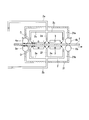
- FIG. 3 is a schematic view showing an example of the plating apparatus.
- the rolls 4a, 4b, 5a, 5b among the rolls 4a, 4b, 5a, 5b, the rolls 4a, 4b disposed on the top of the steel plate 1 are connecting members (conductors) for electrically connecting the power supply (not shown) to the steel plate 1.
- Act as The steel plate 1 is made to be a cathode by being electrically connected to the rolls 4a and 4b.
- a plurality of plating apparatuses shown in FIG. 3 are used in series.
- the base formation step is performed in the region surrounded by the plating apparatus shown in FIG. 3 or the rolls 4a and 5a in FIG. 3 and the intermediate branch paths 2d and 2f.
- the upper layer plating step is performed in a region surrounded by the plating apparatus shown in FIG. 3 or the intermediate branch paths 2d and 2f in FIG. 3 and the rolls 4b and 5b.
- the plating tank 21 includes an upper tank 21 a disposed in the upper part of the steel plate 1 and a lower tank 21 b disposed in the lower part of the steel plate 1. As shown in FIG. 3, at positions adjacent to the steel plate 1 in the upper tank 21a and the lower tank 21b, a plurality of anodes 3 made of platinum or the like are arranged at predetermined intervals with the steel plate 1 There is. The surface of each anode 3 opposed to the steel plate 1 is disposed substantially parallel to the surface of the steel plate 1. Each anode 3 is electrically connected to a power supply (not shown) by a connection member (not shown).
- the upper bath 21 a and the lower bath 21 b are filled with the plating bath 2.
- the steel plate 1 moving with the surface direction being substantially horizontal is disposed between the upper tank 21 a and the lower tank 21 b of the plating tank 21, the steel plate 1 moving with the surface direction being substantially horizontal is disposed.
- the steel plate 1 which has passed through the inside of the plating tank 21 in the direction of the arrow by the rolls 4a, 4b, 5a, 5b is in a state of being immersed in the plating bath 2 in the upper tank 21a and the lower tank 21b. . Therefore, in the present embodiment, the steel plate 1 is transported by the rolls 4a, 4b, 5a, 5b, and the steel plate 1 is moved in the plating bath 2, so that the plating bath 2 flows relatively to the steel plate 1.
- the plating bath 2 is in a flowing state.
- an upper supply piping 2a for supplying the plating bath 2 to the upper tank 21a is provided so as to penetrate the upper surface of the upper tank 21a.
- the upper supply pipe 2a is branched into a plurality of outer peripheral branch paths 2c and a plurality of intermediate branch paths 2d (only one is shown in FIG. 3) in the upper tank 21a.
- a plurality of intermediate branch paths 2d are disposed along the width direction of the steel plate 1 between the adjacent anodes 3 in plan view.
- the middle branch passage 2 d is provided with an opening for supplying the plating bath 2 toward the space between the anode 3 and the steel plate 1 on both sides.
- a plurality of outer peripheral branch paths 2c are disposed along the width direction of the steel plate 1 between the anode 3 and the rolls 4a and 4b in plan view.
- the outer peripheral branch path 2 c is provided with an opening for supplying the plating bath 2 toward the space between the anode 3 and the steel plate 1.
- the upper tank 21a is provided with a discharge port (not shown) for discharging the plating bath 2, and is connected to the upper supply pipe 2a via a pipe (not shown) equipped with a pump. Therefore, in the upper tank 21a, the plating bath 2 supplied from the upper supply pipe 2a and discharged from the discharge port is supplied again from the upper supply pipe 2a via the pipe by the pump and circulated in a flowing state The plating bath 2 is used.
- a lower supply pipe 2b for supplying the plating bath 2 to the lower tank 21b is provided so as to penetrate the lower surface of the lower tank 21b.
- the lower supply pipe 2b is branched into a plurality of outer peripheral branch paths 2e and a plurality of intermediate branch paths 2f (only one is shown in FIG. 3) in the lower tank 21b.
- a plurality of intermediate branch paths 2 f are disposed along the width direction of the steel plate 1 between the anodes 3 adjacent to each other in plan view.
- the middle branch path 2 f is provided with an opening for supplying the plating bath 2 toward the space between the anode 3 and the steel plate 1 on both sides.
- a plurality of outer peripheral branch paths 2e are disposed along the width direction of the steel plate 1 between the anode 3 and the rolls 5a and 5b in plan view.
- the outer peripheral branch path 2 e is provided with an opening for supplying the plating bath 2 toward the space between the anode 3 and the steel plate 1.
- the lower tank 21b is provided with a discharge port (not shown) for discharging the plating bath 2, and is connected to the lower supply pipe 2b via a pipe (not shown) equipped with a pump. Therefore, in the lower tank 21b, the plating bath 2 supplied from the lower supply pipe 2b and discharged from the discharge port is supplied again from the lower supply pipe 2b via the pipe by the pump and circulated. The plating bath 2 is used.
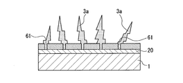
- FIGS. 4A to 4C are schematic views for explaining the state of the surface of the steel plate 1 in the process of manufacturing the surface-treated steel plate 10 shown in FIG.
- the portion of the steel plate 1 having the nickel plating layer (underlayer) 20a formed on the surface passes through between the rolls 4a and 5a and sequentially contacts the plating bath 2 to 18A / dm 2 or less.
- Plating is started at a current density of That is, the rolls 4a and 5a are rolls for conducting electricity and are also called conductor rolls.
- the steel plate and the plating solution come in contact with each other after passing between the conductor rolls 4a and 5a.
- the current concentration portion 61 is a portion on the surface of the steel plate 1 where the vanadium compound 6 is not deposited or a portion where the amount of deposition is small and where current easily flows.
- the deposition potential of Zn is reached, and the reduction deposition reaction of Zn is started.
- the dendritic crystal 3a containing metallic zinc grows, and the upper layer plating step is started.
- the dendritic crystal 3a is grown, it is estimated that the crystal is more likely to grow at the tip of the dendritic crystal 3a.
- the hydrogen 62 thus generated raises the pH of the solid-liquid interface between the surface of the dendritic crystal 3 a and the plating bath 2.
- crystals containing zinc oxide or zinc hydroxide are deposited so as to cover the surface of the dendritic crystal 31, and the dendritic crystal 31 having the surface layer 3b shown in FIG. 1 is formed.
- an amorphous containing hydrated vanadium oxide or vanadium hydroxide is precipitated between adjacent dendritic crystals 31, and the inter-crystal filling region 32 shown in FIG. It is presumed to be formed.
- the current application time is controlled in the range of 0.05 to 8.00 seconds in the base formation step. For this reason, before zinc precipitates on the surface of the steel plate 1, precipitation of the vanadium compound 6 is started, and a plurality of current concentration portions 61 are formed on the surface of the steel plate 1. As a result, it is presumed that a dendritic crystal 31 is obtained by the above-described mechanism, and an inter-crystalline filling region 32 showing an amorphous diffraction pattern is obtained when electron beam diffraction is performed. It is more preferable that the moving time of the steel sheet 1 passing the interval D is in the range of 1.00 to 6.00 seconds.
- the precipitation amount of the vanadium compound 6 deposited before zinc precipitates on the surface of the steel plate 1 as the electricity supply time of a base formation process is less than 0.05 second runs short. For this reason, it becomes difficult to grow the dendritic crystal 31 made of metallic zinc in the current concentration portion 61 formed on the surface of the steel plate 1.
- the intercrystalline filling region 32 containing hydrated vanadium oxide or vanadium hydroxide can not be obtained, or even if the intercrystalline filling region 32 is obtained, the amorphous diffraction pattern becomes unstable. .
- the current passing time in the base forming step exceeds 8.00 seconds, the amount of the vanadium compound 6 deposited before zinc deposits on the surface of the steel sheet 1 is too large, and the current formed on the surface of the steel sheet 1 The number of concentrated parts 61 may decrease or disappear. For this reason, it becomes difficult to grow the dendritic crystal 31 made of metallic zinc, and the diffraction pattern of amorphous even if the dendritic crystal 31 and the intercrystalline filling region 32 can not be obtained or the intercrystalline filling region 32 is obtained. Become unstable.
- electroplating is preferably performed under the condition that the current density is 0 to 18 A / dm 2, and it is more preferable to perform electroplating under the condition of 2 to 15 A / dm 2. preferable.
- the molar ratio (V / Zn) of vanadium to zinc in the intercrystalline filling region 32 becomes 0.10 or more and 2.00 or less, and the electron
- the intercrystalline filling region 32 exhibits an amorphous diffraction pattern, and as a result, barrier properties and coating film adhesion can be improved.
- the current density in the base formation step is not within the above range, the intercrystalline filling region 32 is not formed, or the amorphous diffraction pattern becomes unstable even if the intercrystalline filling region 32 is formed.
- electroplating is preferably performed under the condition that the current density is 21 to 200 A / dm 2 .
- the current density is 21 A / dm 2 or more, hydrogen 62 can be generated sufficiently at the solid-liquid interface between the tip of the branch of the dendritic crystal 31 and the plating bath 2. Therefore, the precipitation amount of the hydrated vanadium oxide or vanadium hydroxide contained in the intercrystalline filling region 32 is increased.
- the plating layer 30 having a high vanadium content and excellent barrier properties can be formed. If the current density exceeds 200 A / dm 2 , the plated structure may be roughened or a crack may easily occur, and thus the adhesion between the plated layer 30 and the steel plate 1 may be reduced.
- the average flow velocity of the plating bath 2 in the plating tank 21 when plating is preferably in the range of 20 to 300 m / min, and more preferably in the range of 40 to 200 m / min.
- the average flow velocity of the plating bath 2 is in the range of 20 to 300 m / min, generation of cracks in the plating 30 layer can be prevented, and ions can be supplied from the plating bath 2 to the surface of the steel sheet 1 without any problem. it can.
- the plating bath 2 one containing a V compound and a Zn compound is used.
- a pH adjuster another V compound and another metal compound that is not a Zn compound, and an additive may be added to the plating bath 2.
- pH adjusters include H 2 SO 4 and NaOH.
- the additive include Na 2 SO 4 which stabilizes the conductivity of the plating bath 2.
- NiSO 4 .6H 2 O nickel compounds
- the plating bath 2 contains a nickel compound, it is preferable that the plating bath 2 contains 0.01 mol / l or more of Ni 2+ . By this, the plating layer 30 which contains nickel sufficiently can be formed. The plating layer 30 containing nickel is preferable because excellent plating adhesion can be obtained.
- Examples of the Zn compound used in the plating bath 2 include metal Zn, ZnSO 4 .7H 2 O, ZnCO 3 and the like. These may be used alone or in combination of two or more.
- a V compound used for the plating bath 2 ammonium metavanadate (V), potassium metavanadate (V), sodium metavanadate (V), VO (C 5 H 7 O 2 ) 2 (vanadyl acetylacetonate (V) IV), VOSO 4 .5H 2 O (vanadyl sulfate (IV)) and the like. These may be used alone or in combination of two or more.
- Plating bath 2 it is preferable to use one containing Zn 2+ and VO 2+ .
- Plating bath 2 when it is intended to include Zn 2+, preferably comprises Zn 2+ 0.10 ⁇ 4.00mol / l, and more preferably contains 0.35 ⁇ 2.00mol / l.
- Plating bath 2 when it is intended to include VO 2+, preferably contains less than 0.01 mol / l or higher 2.00 mol / l of VO 2+ in the plating bath 2.
- the plating bath 2 it is preferable to use one containing 0.10 mol / l or more of Na + in the plating bath 2. In this case, the conductivity of the plating bath 2 can be enhanced, and the plating layer 30 of the present embodiment can be easily formed.
- the temperature of the plating bath 2 is not particularly limited, but is preferably in the range of 40 to 60 ° C. in order to easily and efficiently form the plating layer 30 of the present embodiment. Further, the pH of the plating bath 2 is preferably in the range of 1 to 5, and more preferably in the range of 1.5 to 4 in order to easily form the plating layer 30 of the present embodiment.
- a treatment agent for improving the barrier property, fingerprint resistance, scratch resistance, lubricity, design property, etc. is applied on the plating layer 30.
- the surface layer 40 is formed.
- the surface-treated steel sheet 10 shown in FIG. 1 is obtained by the above steps.
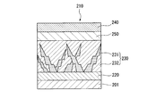
- the surface-treated steel plate 210 of the present embodiment includes a steel plate 201 and a plating layer 230 formed on one side or both sides of the steel plate.
- the plating layer 230 contains zinc and zirconium.
- the plating layer 230 also contains dendritic crystals 231 containing metallic zinc and an intercrystalline filling region 232 containing one or both of hydrated zirconium oxide or zirconium hydroxide.
- the surface-treated steel plate 210 will be described in detail.
- the plating layer 230 includes the dendritic crystal 231 containing metallic zinc and the intercrystalline filling region 232 containing one or both of hydrated zirconium oxide or zirconium hydroxide.
- the dendritic crystal 231 is a dendritic crystal phase containing metallic zinc, and the intercrystalline packing region 232 contains one or both of hydrated zirconium oxide or zirconium hydroxide, and around the dendritic crystal 231 It is formed and has an amorphous pattern by electron diffraction.
- the plating layer 230 has a configuration in which the dendritic crystal 231 is deposited first, and then the intercrystalline filling region 232 is deposited around the dendritic crystal 231.
- the dendritic crystal 31 of the first embodiment has the interior 3a and the surface layer 3b.
- the interior 3a of the dendritic crystal 31 preferably contains metallic zinc, and may contain other metallic components such as nickel.
- the surface layer 3b of the dendritic crystal 31 preferably contains zinc oxide or zinc hydroxide, and more preferably contains crystals of hydrated zinc oxide.
- the dendritic crystal 231 of the present embodiment does not have the inside and the surface layer.
- the dendritic crystal 231 may be formed only of metallic zinc, and may contain, together with metallic zinc, another metallic component such as nickel which is more noble than the deposition potential of zinc.
- the dendritic crystal 231 grows from the steel plate 201 side toward the surface of the plating layer 230 along the thickness direction of the plating layer 230, and has a branched structure toward the surface of the plating layer 230.
- the dendritic crystal 231 contains metallic zinc, sacrificial corrosion resistance can be imparted to the plating layer 230.
- the inter-crystal packing region 232 may contain zinc oxide in addition to containing one or both of hydrated zirconium oxide and zirconium hydroxide. The inclusion of these inclusions in the inter-crystal filling region 232 can provide the plated layer 230 with a barrier property. Further, since the inter-crystal filling region 232 is mainly made of hydrated oxide or hydroxide, when the coating film is formed in the inter-crystal filling region 232, the coating film adhesion can be secured. The intercrystalline filling region 232 exhibits an amorphous diffraction pattern when electron diffraction is performed.
- the molar ratio (Zr / Zn) of zirconium to zinc in the intercrystalline filling region 232 is 1. It is preferable that it is 00 or more and 3.00 or less.
- the above-mentioned molar ratio (Zr / Zn) is in the above-mentioned range, and when the electron beam diffraction is performed, the intercrystalline filling region 232 exhibits an amorphous diffraction pattern, so that excellent corrosion resistance (barrier property) and Coating film adhesion is obtained.
- an amorphous layer 250 may be formed which exhibits an amorphous diffraction pattern when electron diffraction is performed. It is presumed that the amorphous layer 250 is formed first when the plating layer 230 is formed. That is, first, the amorphous layer 250 is formed on the steel plate 201, and then the plating layer 230 including the dendritic crystal 231 and the inter-crystal filling region 232 is grown between the steel plate 201 and the amorphous layer 250. It is guessed that.
- the amorphous layer 250 is a layer mainly composed of zirconium oxide, and may contain a trace amount of zinc.
- the amorphous layer 250 exhibits barrier properties by being formed on the plating layer 230.
- the amorphous layer 250 can be removed by immersing the steel plate 201 having the plating layer 230 in an acidic solution after forming the plating layer 230.
- the amorphous layer 250 may be removed from the surface-treated steel sheet 201 by such a process.
- the plating layer 230 is exposed by removing the amorphous layer 250.
- the surface of the plating layer 230 has a surface roughness higher than that of the amorphous layer 250, and has excellent coating film adhesion as compared with the case where the amorphous layer 250 is formed.
- the adhesion amount of the plating layer 230 is preferably 1 g / m 2 or more, and preferably 3 g / m 2 or more, in order to improve the barrier property.
- the adhesion amount of the plating layer 230 is preferably 60 g / m 2 or less, more preferably 40 g / m 2 or less, and still more preferably 20 g / m 2 or less.
- the adhesion amount of the plating layer 230 is 20 g / m 2 or less, the amount of metal to be deposited may be smaller than that of conventional electrogalvanization (usually about 20 g / m 2 ) or the like. In addition, when the adhesion amount is too large, the plating layer 230 is easily cracked.
- the thickness of the plating layer 230 is preferably in the range of 0.5 to 40 ⁇ m, more preferably in the range of 1.0 to 20 ⁇ m, and still more preferably in the range of 2.0 to 15 ⁇ m. If the thickness of the plating layer 230 is not less than the lower limit, the barrier property can be improved. In addition, when the thickness of the plating layer 230 is equal to or less than the upper limit, a crack is less likely to occur in the plating layer 230.
- the thickness of the plating layer 230 can be controlled by adjusting the amount of power to be applied when electroplating.
- the thickness of the amorphous layer 250 is preferably 0.20 to 2.00 ⁇ m, more preferably 0.30 to 1.50 ⁇ m, and still more preferably 0.50 to 1.00 ⁇ m. If the thickness of the amorphous layer 250 is not less than the upper limit, the plated layer 230 can be provided with a barrier property. In addition, when the thickness of the amorphous layer 250 is equal to or less than the lower limit, the occurrence of a crack can be prevented and the barrier property can be secured.
- the thickness of the amorphous layer 250 can be controlled by adjusting the Zr concentration in the plating bath at the time of electroplating. That is, as the Zr concentration in the plating bath at the time of electroplating is increased, the thickness of the amorphous layer 250 can be increased.
- the plating layer 230 is composed of Zr: 3 to 40 atm%, Zn: 3 to 40 atm%, and the balance of oxygen and impurities in average concentration. If Zr in the plating layer 230 is 3 atm% or more, the barrier property can be enhanced. Moreover, if Zr in the plating layer 230 is 40 atm% or less, generation
- the dendritic crystal 231 contains metal Zn as described above, and may further contain Ni or the like.
- TEM transmission electron microscope
- the intercrystal filling region 232 is composed of Zr: 10 to 80 atm%, Zn: 3 to 40 atm%, and the balance of oxygen and impurities in average concentration. If Zr in the inter-crystal filling region 232 is 10 atm% or more, the barrier property can be enhanced. Moreover, if Zr in the inter-crystal filling region 232 is 80 atm% or less, generation of a crack in the plating layer 230 can be prevented, and barrier properties can be ensured. In addition, if Zn in the inter-crystal filling region 232 is 3 atm% or more, the barrier property can be enhanced. In addition, if Zn in the inter-crystal filling region 232 is 40 atm% or less, the amount of Zr can be relatively secured, and the barrier property of the plating layer 230 can be improved.
- the amorphous layer 250 is composed of Zr: 10 to 60 atm%, Zn: 0 to 15 atm%, balance oxygen and impurities in average concentration. If Zr in the amorphous layer 250 is 10 atm% or more, the barrier property can be enhanced. In addition, when Zr in the amorphous layer 250 is 60 atm% or less, generation of a crack can be prevented and the barrier property can be secured.
- the amorphous layer 250 may contain a slight amount of Zn or may not contain Zn.
- the base layer 220 may be formed between the steel plate 201 and the plating layer 230 as in the first embodiment.
- the surface layer 240 may be formed on the plating layer 230 (the amorphous layer 250 when the amorphous layer 250 is formed).
- the L * value representing the lightness is 40 or less, and has a black appearance. By having a black appearance, it can be used for various applications. When the L * value is over 40, it is difficult to use as a material having a black appearance. In particular, by setting the Zr concentration in the plating layer 230 to 5% by mass or more, the L * value can be reliably reduced to 40 or less.
- the surface-treated steel plate 210 of this embodiment of this embodiment demonstrated the example which formed the plating layer 230 on the steel plate 201
- this embodiment is not restricted to this, An electrogalvanized steel plate, a hot dip galvanized steel plate
- the plating layer 230 of the present embodiment may be formed on the galvanized layer of the alloyed galvanized steel sheet. That is, between the steel plate 201 and the plating layer 230, a second galvanized layer (not shown) containing zinc may be further formed.
- the corrosion resistance of the surface-treated steel sheet 210 can be further improved.
- the second zinc plating layer (not shown) can exhibit a sacrificial corrosion protection effect, and can improve the corrosion resistance of the surface-treated steel sheet 210.
- Method of manufacturing surface-treated steel sheet 210 Next, a method of manufacturing the surface-treated steel plate 210 will be described.
- the manufacturing method of the surface-treated steel sheet 210 is different only in the manufacturing method of the surface-treated steel sheet 1 according to the first embodiment and the composition of the plating bath, and the other points are the same.
- the method of manufacturing the surface-treated steel plate 210 includes a base forming step and an upper layer plating step, as in the first embodiment.
- the same plating bath is used in the base formation step and the upper layer plating step, and a plating bath containing a Zr compound (ZrO 2+ ) and a Zn compound (Zn 2+ ) is used.
- a Zr compound what forms ZrO ⁇ 2+> ion in a plating bath is preferable,
- soluble salts such as a zirconium nitrate oxide, a sulfuric acid zirconium oxide, a zirconium chloride nitric oxide oxide, etc. can be illustrated. These may be used alone or in combination of two or more.
- the plating bath preferably contains 0.10 to 4.00 mol / l, more preferably 0.50 to 2.00 mol / l, of Zn 2+ .
- the content of ZrO 2+ is preferably 0.10 to 4.00 mol / l, more preferably 0.50 to 2.00 mol / l.
- a pH adjuster a Zr compound and another metal compound that is not a Zn compound, an additive, and the like may be added to the plating bath.
- the current density in the base formation step and the upper layer plating step is the same as in the first embodiment, and thus the description thereof is omitted.
- the present invention is not limited to the embodiments described above.
- the case where the plating layer is formed on both sides of the steel plate is described as an example, but the plating layer may be formed only on one side of the steel plate.
- the base layer is formed between the steel plate and the plating layer, the base layer may not be formed.
- the foundation layer may be formed only between the steel plate on one side and the plating layer.
- the case where the plating layer contains vanadium and the case where the plating layer contains zirconium are separately described, but these embodiments may be provided simultaneously.
- the surface layer does not need to be formed. Since the surface-treated steel sheet of the present embodiment is excellent in barrier property, it is not necessary to form a surface layer for improving the barrier property on the surface of the plating layer. When the plating layer is formed on both sides of the steel plate, the surface layer may be formed only on the surface of the plating layer on one side.
- the plating apparatus which manufactures a surface-treated steel plate is the plating apparatus shown in FIG. It is not limited.
- the number of anodes 3 may be any number.
- the size and shape of the plating tank 21, the steel plate 1 and the anode 3, and the arrangement and shape of the upper supply pipe 2 a and the lower supply pipe 2 b are not particularly limited. It can be determined accordingly.
- a 0.5-mm-thick SPCD plate for drawing of a cold-rolled steel plate specified in JIS G 3141 was used.
- the above steel plate was subjected to pretreatment (nickel plating) and used as a cathode.
- pretreatment nickel plating
- the pH was adjusted to 2.0.
- each energization time was a time shown in Tables 2 and 3, and a plating layer was formed by electroplating.
- ZnSO 4 ⁇ 7H 2 O is used as the Zn compound
- VOSO 4 ⁇ 5H 2 O is used as the V compound
- Na 2 SO 4 and other metal compounds as needed.
- NiSO 4 ⁇ 6 H 2 O was used as By adjusting these contents, the concentrations of Zn 2+ , V (V 4 + , VO 2 + ), Na + and Ni 2+ shown in Table 1 were adjusted.
- FE-TEM field emission type transmission electron microscope
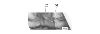
- 5A to 5C are transmission electron microscope (TEM) photographs of the plated layer of the surface-treated steel sheet of Example V4.
- 5A is a cross-sectional photograph of the entire plating layer 30 formed on the steel plate 1 in the thickness direction
- FIG. 5B is a magnified photograph of the interface between the steel plate and the plating layer in the cross section of FIG. 5A
- FIG. It is an enlarged photograph of a dendritic crystal and its surrounding portion in a cross section of
- reference numeral 51 denotes a base layer
- reference numeral 52 denotes an intercrystalline filling region in the vicinity of the interface between the steel plate and the plating layer.
- reference numeral 53 denotes a dendritic crystal
- reference numeral 54 denotes an inter-crystal filling region
- reference numeral 55 denotes a surface layer formed on the surface of the dendritic crystal.
- the plated layers of the surface-treated steel sheets of Examples V1 to V3 and V5 to V20 were also observed using a TEM, as in Example V4. As a result, in the plating layer, a dendritic crystal, an intercrystalline filling region, and a surface layer of a dendritic crystal were formed.
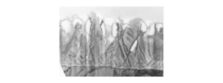
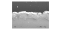
- FIG. 6 is a scanning electron microscope (SEM) photograph of the plated layer of the surface-treated steel sheet of Example V4.
- reference numeral 56 denotes a dendritic crystal
- reference numeral 57 denotes an intercrystalline filling region disposed between the dendritic crystals
- reference numeral 58 denotes a surface layer covering the surface of the dendritic crystal.
- the white part of the surface of a plating layer is the gold film vapor-deposited in order to observe a plating layer.
- the plated layers of the surface-treated steel plates of Examples V1 to V3 and V5 to V20 also had dendritic crystals, an intercrystalline filling region, and a surface layer of dendritic crystals formed in the same manner as the plated layer of Example V4.
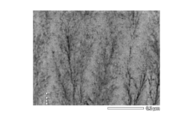
- FIG. 7 is a scanning electron microscope (SEM) photograph of the plated layer of the surface-treated steel sheet of Comparative Example x2. As shown in FIG. 7, the plating layer of Comparative Example x2 was a single phase composed of dendritic crystals.
- Example V1 to Example V20 dendritic crystal, intercrystalline filling region, dendritic crystal, respectively, using an energy dispersive X-ray analyzer (EDS) (manufactured by JEOL Ltd. (JED-2300T)) Elemental analysis of the surface layer of Then, the element (composition) contained in the dendritic crystal, the element (composition) contained in the intercrystalline filling region, the amount of vanadium and zinc thereof, and the element (composition) contained in the surface layer of the dendritic crystal were examined. In addition, using the result of elemental analysis, the molar ratio (V / Zn) of the amount of vanadium to the amount of zinc in the intercrystalline filling region was calculated.
- EDS energy dispersive X-ray analyzer
- the surface layer of the dendritic crystal, the intercrystalline filling region, and the dendritic crystal is a crystal using an electron beam diffraction image obtained by TEM from the cross sectional direction. It was confirmed whether it had a structure or was amorphous.
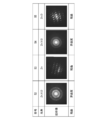
- FIG. 8 is a photograph showing an electron beam diffraction image of the plating layer of Example V4. The symbols attached to the photographs shown in FIG. 8 correspond to the intercrystalline filling region 52, the dendritic crystal 53, the intercrystalline filling region 54, and the surface layer 55 of the dendritic crystal shown in FIGS. 5B and 5C, respectively. From the electron beam diffraction image shown in FIG.
- the dendritic crystal 53 and the surface layer 55 of the dendritic crystal had a crystal structure.
- the intercrystalline filling regions 52 and 54 were amorphous because the diffraction pattern due to the crystal structure was not obtained.
- the surface layer of the dendritic crystal, the intercrystalline filling region, and the dendritic crystal each has a crystal structure or is amorphous similarly to Example V4. It was confirmed. As a result, it was found that the surface layer of the dendritic crystal and the dendritic crystal had a crystal structure, and the intercrystalline filling region was amorphous. In addition, when the impurities in the dendritic crystal were examined, C, Si, S, Fe, and N were each about 0.1 to 5 atm%.
- the adhesion amount of the plating layer was the total mass per unit area of the Zn element and the V element detected using a fluorescent X-ray apparatus (Simultix 14 manufactured by Rigaku Corporation). Further, the vanadium content in the plating layer was calculated as a percentage by dividing the amount of V element detected by the fluorescent X-ray apparatus by the adhesion amount.
- the edge and back surface of the test piece cut out from the surface-treated steel sheet were tape-sealed, and a salt spray test (JIS-Z-2371) was performed. And the white rust generation area rate of the non-sealed part after 72 hours was observed visually, and the following references
- the white rusting area ratio is a percentage of the area of the white rusting site to the area of the observation site.
- Powdering property adheresion between plated layer and steel sheet
- a 60 ° V bending mold was used for the powdering test. Bending at 60 ° using a die with a curvature radius of 1 mm at the tip so that the evaluation surface of the test piece cut out from the surface-treated steel plate is on the inside of the bending portion, and a tape is attached to the inside of the bending portion , I peeled off the tape. Powdering property (peeling width (mm)) was evaluated from the peeling condition of the plating layer peeled with the tape.
- a paint (Amilac # 1000, manufactured by Kansai Paint Co., Ltd.) was bar-coated on a test piece cut out of a surface-treated steel plate and baked at 140 ° C. for 20 minutes to form a dry film having a thickness of 25 ⁇ m.
- the resulting coated plate was immersed in boiling water for 30 minutes and then left in a room at normal temperature for 24 hours. Thereafter, 100 square grids of 1 mm square are cut into the test piece with an NT cutter, and this is extruded 7 mm with an Erichsen testing machine, and then this extrusion convex portion is subjected to a peeling test with an adhesive tape to obtain coating film adhesion ( The number of peeled pieces was evaluated.
- the coating composition for forming a film comprises an organic resin (R), a phosphoric acid compound (P), a carbon black (C), an organosilicon compound (W) and a fluorometal complex compound (shown in Table 8) F), the isocyanate compound (I) and the polyethylene wax (Q) are stirred in water as a solvent using the paint disperser at contents (% by mass of solid content) shown in Table 9 and Table 10 The mixture was dispersed to prepare a paint composition.
- R organic resin
- P a phosphoric acid compound
- C carbon black
- W organosilicon compound
- Q fluorometal complex compound
- 3-aminopropyltriethoxysilane (W1) and 3-glycidoxypropyltrimethoxysilane (W2) shown in Table 8 are ratios shown in Table 9 and Table 10 [(W1)
- generated was added as an organosilicon compound (W) so that it might become content shown in Table 9 and Table 10.
- a film was formed by the following method using the above-mentioned paint composition.
- a paint composition was applied to the surface of the surface-treated steel sheet using a roll coater so as to obtain the film thickness shown in Table 11 and Table 12.
- the surface-treated steel sheet coated with the coating composition was dried by heating so as to reach a plate reaching temperature of 150 ° C., and spray cooled using water to obtain a film.
- the hydrated oxide was still present in the plating layer even after heating to 150 ° C.
- each surface-treated steel plate in which the film was formed on the surface of the plating layer was evaluated for appearance uniformity, corrosion resistance, conductivity, processing adhesion, and scratch resistance. Further, as a reference example e2, the appearance uniformity, the corrosion resistance, the conductivity, the working adhesion, and the scratch resistance of the surface-treated steel sheet of Example V4 manufactured in (Example 1) were evaluated. The evaluation results of each item are shown in Table 11 and Table 12.
- the evaluation method and evaluation criteria for each item are shown below. (Appearance uniformity)
- the L * value of the surface-treated steel sheet was measured using a colorimeter CR-400 manufactured by Konica Minolta Co., Ltd., and evaluated according to the following evaluation criteria.
- L * value is less than 24 4: L * value is 24 or more, less than 27 3: L * value is 27 or more, less than 28 2: L * value is 28 or more, less than 30 1: L * value is more than 30
- the edge and back surface of the test piece cut out from the surface-treated steel plate were tape-sealed, and a salt spray test (JIS Z 2371) was performed. And the white rust generation area rate of the non-sealed part after 240 hours was observed visually, and the following references evaluated.
- the white rusting area ratio is a percentage of the area of the white rusting site to the area of the observation site.
- the interlayer resistance value ( ⁇ ⁇ cm 2 ) was measured by the measurement method defined in JIS C 2550 using the test piece cut out from the surface-treated steel sheet, and the conductivity was evaluated according to the following criteria.
- Interlayer resistance value is less than 1.0 ⁇ ⁇ cm 2 5: Interlayer resistance value is 1.0 ⁇ ⁇ cm 2 or more, less than 1.5 ⁇ ⁇ cm 2 4: Interlayer resistance value is 1.5 ⁇ ⁇ cm 2 or more 2. 0 ⁇ ⁇ cm 2 or less 3: Interlayer resistance value is 2.0 ⁇ ⁇ cm 2 or more, less than 2.5 ⁇ ⁇ cm 2 2: Interlayer resistance value is 2.5 ⁇ ⁇ cm 2 or more, less than 3.0 ⁇ ⁇ cm 2 1: Interlayer Resistance value is 3.0 ⁇ ⁇ cm 2 or more
- the test material cut out from the surface-treated steel plate was brought into close contact with the electrogalvanized steel plate (non-treated material), and the test material was rotated 90 ° in a pressurized state.
- the pressurization was 0.2 kg / cm 2 , and the test temperature was 25 ° C. Thereafter, the appearance of the test material was visually evaluated.
- the evaluation result is 2 or more of the evaluation criteria in any of the evaluation items. It showed excellent appearance uniformity, corrosion resistance, conductivity, processing adhesion and scratch resistance. In addition, the examples t1 to t14 had better corrosion resistance and conductivity as compared with the reference example e2 in which no film was formed on the surface.
- Comparative Examples w1 to w5 having a film on the surface of the plated layer of the surface-treated steel sheet of Comparative Example x3 the evaluation results of appearance uniformity, corrosion resistance after 240 hours, processing adhesion and scratch resistance are 1. , The performance was inferior.
- Test results of zirconium-containing surface-treated steel sheet Using the plating apparatus shown in FIG. 2, a surface-treated steel plate having a plating layer containing zirconium on both sides of the steel plate was prepared and evaluated by the method described below. The description of the same matters as in the first embodiment will be omitted.
- a flowing plating bath was prepared by circulating the plating baths having the composition, temperature and pH shown in Table 13 at an average relative flow rate of 100 m / min.
- a steel plate was used as a cathode for pretreatment (nickel plating).
- a current flow time was set to a time shown in Tables 14 and 15
- a current density was set to a numerical value shown in Tables 14 and 15
- a plating layer was formed by electroplating.
- ZnSO 4 ⁇ 7H 2 O is used as the Zn compound
- a ZrO (NO 3 ) 2 aqueous solution or a ZrOSO 4 aqueous solution is used as the Zr compound, and further, Na 2 SO 4 or others as needed.
- NiSO 4 ⁇ 6 H 2 O was used as a metal compound of By adjusting these contents, the concentrations of Zn 2+ , Zr (Zr 4 + , ZrO 2 + ), Na + and Ni 2+ shown in Table 1 were adjusted.
- FE-TEM field emission type transmission electron microscope
- FIG. 9 is a transmission electron microscope (TEM) photograph of the plated layer of the surface-treated steel sheet of Example Z4.
- TEM transmission electron microscope
- the dendrite-like crystals were found to be composed of Zn metal by elemental analysis and electron beam diffraction analysis with an energy dispersive X-ray analyzer (EDS (JED-2300T) manufactured by JEOL Ltd.) and the intercrystalline filling region.
- EDS energy dispersive X-ray analyzer
- the amorphous layer in the surface layer was made of zirconium oxide.
- Example Z4 dendritic crystals, an intercrystalline filling region formed around the same, and an amorphous layer in the surface layer portion were formed. In addition, the amorphous layer in the surface layer was also removed in some cases.
- Example Z1 to Example Z20 For the plated layers of Example Z1 to Example Z20, “Dendrite-like crystals”, “intercrystalline filling region” “each using an energy dispersive X-ray analyzer (EDS) (manufactured by JEOL Ltd. (JED-2300T)) Elemental analysis of “surface layer of dendritic crystal” was performed. Then, the element (composition) contained in the dendritic crystal, the element (composition) contained in the intercrystalline filling region, the amount of zirconium and zinc thereof, and the element (composition) contained in the surface layer of the dendritic crystal were examined. Moreover, the molar ratio (Zr / Zn) of the amount of zirconium of the filling area between crystals and the amount of zinc was calculated using the result of elemental analysis.
- EDS energy dispersive X-ray analyzer
- the plated layers of the surface-treated steel sheets of Comparative Example x11 to Comparative Example x16 were analyzed using an X-ray diffractometer (XRD: RINT 2500 manufactured by Rigaku Corporation). As a result, it was confirmed that the dendritic crystal had a Zn crystal structure in the plated layers of Comparative Examples x11 to x16. In addition, it is confirmed that only an unstable amorphous diffraction pattern can be obtained when no intercrystalline filling region is formed (comparative example x 15) or even if it is formed (comparative examples x 11 to x 14 and x 16). did.
- XRD X-ray diffractometer
- the adhesion amount of the plating layer was the total mass per unit area of Zn element and Zr element detected using a fluorescent X-ray apparatus (Simultix 14 manufactured by Rigaku Corporation). Further, the zirconium content in the plating layer was calculated as a percentage by dividing the Zr element amount detected by the fluorescent X-ray apparatus by the adhesion amount.
- Comparative Example current density in the base forming step is 25A / dm 2 x12 ⁇
- the molar ratio (Zr / Zn) of zirconium to zinc in the inter-crystal filling region is 1.00 or more and 3.00 or less, and electron beam diffraction is performed, unlike the plating layer of the surface-treated steel sheet of x13
- the intercrystalline filling region showed an amorphous diffraction pattern.
- barrier property and coating-film adhesiveness are more excellent.
- the coating composition for forming a film comprises an organic resin (R), a phosphoric acid compound (P), a carbon black (C), an organosilicon compound (W) and a fluorometal complex compound (shown in Table 8) F), the isocyanate compound (I) and the polyethylene wax (Q) are stirred in water as a solvent using the paint disperser at the contents (% by mass of solid content) shown in Table 20 and Table 21 The mixture was dispersed to prepare a paint composition. Description of the same matters as in the second embodiment will be omitted.
- a film was formed by the following method using the above-mentioned paint composition.
- the coating composition was applied to the surface of the surface-treated steel sheet using a roll coater so as to obtain the film thickness shown in Table 22 and Table 23.
- the surface-treated steel sheet coated with the coating composition was dried by heating so as to reach a plate reaching temperature of 150 ° C., and spray cooled using water to obtain a film.
- the hydrated oxide was still present in the plating layer even after heating to 150 ° C.
- each surface-treated steel plate in which the film was formed on the surface of the plating layer was evaluated for appearance uniformity, corrosion resistance, conductivity, processing adhesion, and scratch resistance. Further, as a reference example f1, evaluation of appearance uniformity, corrosion resistance, conductivity, processing adhesion, and scratch resistance of the surface-treated steel sheet of Example Z4 manufactured in (Example 3) was performed. The evaluation results of each item are shown in Table 22 and Table 23.
- Examples u1 to u14 having a film on the surface of the plated layer of the surface-treated steel sheet of Example Z4 have an evaluation result of 2 or more of the evaluation criteria in any of the evaluation items. It showed excellent appearance uniformity, corrosion resistance, conductivity, processing adhesion and scratch resistance. Further, in the examples u1 to u14, the corrosion resistance and the conductivity were good as compared with the reference example f1 in which the film was not formed on the surface.
- Comparative Examples y1 to y5 having a film on the surface of the plated layer of the surface-treated steel sheet of Comparative Example x13 the evaluation results of appearance uniformity, corrosion resistance after 240 hours, processing adhesion, and scratch resistance are 1. , The performance was inferior.
Landscapes
- Chemical & Material Sciences (AREA)
- Engineering & Computer Science (AREA)
- Chemical Kinetics & Catalysis (AREA)
- Electrochemistry (AREA)
- Materials Engineering (AREA)
- Metallurgy (AREA)
- Organic Chemistry (AREA)
- Crystallography & Structural Chemistry (AREA)
- Inorganic Chemistry (AREA)
- Other Surface Treatments For Metallic Materials (AREA)
- Electroplating Methods And Accessories (AREA)
- Electroplating And Plating Baths Therefor (AREA)
- Chemical Treatment Of Metals (AREA)
Abstract
Description
本願は、2015年6月9日に、日本に出願された特願2015-116554号及び特願2015-116604号に基づき優先権を主張し、その内容をここに援用する。
電気亜鉛めっき鋼板のバリア性を向上させる方法としては、亜鉛めっき層のめっき量(目付け量)を増加させることが考えられる。しかしながら、亜鉛めっき層の目付け量を増加させた場合、製造コストが増大し、加工性や溶接性が低下するという問題があった。
特許文献1には、亜鉛系めっき鋼板のめっき層の表層部にV濃化層を形成する技術が記載されている。
特許文献2には、亜鉛及びバナジウムを含み、複数のデンドライト状のアームを有するめっき層に関する技術が記載されている。
また、V(バナジウム)は稀少な元素であることから、亜鉛バナジウムめっきに代わる、バリア性に優れためっきが所望されている。
本発明は、このような事情に鑑みてなされたものであって、鋼板の表面に、亜鉛とバナジウムまたはジルコニウムとを含むめっき層が形成された、バリア性及び塗膜密着性に優れた表面処理鋼板を提供することを課題とする。
すなわち、本発明者は、電気めっき法で、鋼板を陰極として種々の条件で、亜鉛とバナジウムまたはジルコニウムとを含むめっき層を鋼板の表面に形成し、そのバリア性と塗膜密着性を調査した。
また、本発明者は、ある条件下において、金属亜鉛からなるデンドライト状結晶の周囲に、水和したジルコニア酸化物またはジルコニア水酸化物を含む相が形成されることを見出した。このようなめっき層は、亜鉛バナジウムめっきとの比較で、バリア性が同等以上であり、かつ塗膜密着性に優れることが判明し、本発明を完成するに至った。本発明の各態様は以下の通りである。
(2)上記(1)に記載の表面処理鋼板では、前記めっき層が前記バナジウムを含む場合に、前記結晶間充填領域中の前記バナジウムと前記亜鉛とのモル比であるV/Znが、0.10以上2.00以下であり、前記めっき層が前記ジルコニウムを含む場合に、前記結晶間充填領域中の前記ジルコニウムと前記亜鉛とのモル比であるZr/Znが、1.00以上3.00以下である構成を採用してもよい。
(3)上記(1)または(2)に記載の表面処理鋼板では、前記めっき層が前記バナジウムを含む場合であって、前記デンドライト状結晶の表層が、亜鉛酸化物または亜鉛水酸化物を含む構成を採用してもよい。
(5)上記(1)~(4)のいずれか一項に記載の表面処理鋼板では、前記めっき層の表面に、ポリウレタン樹脂と、1~20質量%のカーボンブラックとを有する有機樹脂皮膜をさらに備える構成を採用してもよい。
(6)本発明の一態様に係る表面処理鋼板の製造方法は、上記(1)~(5)のいずれか一項に記載の表面処理鋼板を製造する方法であって、0.10~4.00mol/lのZn2+イオンと、0.01~2.00mol/lのVイオンまたは0.10~4.00mol/lのZrイオンとを含有するめっき浴を用いて、0~18A/dm2の電流密度で電気めっきを行うことにより、前記鋼板上に水和したバナジウム酸化物、またはバナジウム水酸化物を析出させて凹凸を形成する下地形成工程と;前記凹凸を形成した前記鋼板に、前記めっき浴を用いて、21~200A/dm2の電流密度で電気めっきを行う上層めっき工程と;を有する。
以下、図面を参照して、めっき層がバナジウムを含有する場合の第1実施形態の表面処理鋼板10について詳細に説明する。
図1は、本実施形態に係る表面処理鋼板10の一例を説明するための断面模式図である。図1に示す表面処理鋼板10は、鋼板1の両面にそれぞれ、下地層20とめっき層30と表面層40とが鋼板1側から順に形成されているものである。図1においては、鋼板1の一方の面(上面)側に形成されている下地層20とめっき層30と表面層40のみ記載し、他方の面(下面)側の記載を省略している。
本発明において「非晶質」とは、透過型電子顕微鏡(TEM)を用いて断面方向から各層毎に電子線回折を行って、結晶構造に起因する回折パターンが得られないことを意味する。
また、結晶間充填領域32は、亜鉛を含むことが好ましい。結晶間充填領域32が亜鉛を含むことにより耐食性が向上する。
また「デンドライト状結晶31の断面視したときの最大幅」とは、透過型電子顕微鏡(TEM)を用いてめっき層の断面を観察し、50本のデンドライト状結晶31の最大幅を測定し、その平均値を算出することにより求めたものである。
また、表層3bは、亜鉛酸化物または亜鉛水酸化物を含む結晶を含むことが好ましい。表層3bは、亜鉛酸化物の結晶を含むことがより好ましい。表層3bの厚みは、0.1~500nmであることが好ましい。
下地めっき層(不図示)は、亜鉛とバナジウムとを含んでかつ、当該亜鉛と当該バナジウムとのモル比であるZn/Vが8.00以上であってもよい。また、下地めっき層(不図示)は、亜鉛のみから構成されていてもよい。
上層めっき層(不図示)は亜鉛のみから構成されていてもよい。また、上層めっき層(不図示)は、亜鉛とバナジウムとを含んでかつ、当該亜鉛と当該バナジウムとのモル比であるZn/Vが8.00以上であってもよい。
下地めっき層(不図示)と同様の方法で、上層めっき層(不図示)をめっき層30上に形成することができる。
上記のモル比(a/b)が0.10以上であると、めっき層30の表面に傷が発生した場合に、デンドライト状結晶31に含まれる金属亜鉛による犠牲防食作用が効果的に得られるものとなり、より優れたバリア性が得られる。デンドライト状結晶31に含まれる金属亜鉛による犠牲防食作用をより効果的に得るためには、上記のモル比(a/b)を0.20以上とすることがより好ましい。
また、上記のモル比(a/b)が3.00以下である場合、デンドライト状結晶31の表層に含まれる亜鉛酸化物または亜鉛水酸化物が空気や水を通しにくいことに起因する鋼板1のバリア性向上作用が効果的に得られるものとなり、より優れたバリア性が得られる。デンドライト状結晶31の表層3bによるバリア性向上作用をより効果的に得るためには、上記のモル比(a/b)は0.25以下であることがより好ましい。
デンドライト状結晶31による犠牲防食作用とデンドライト状結晶31の表層3bによるバリア性向上作用とをより効果的に得るために、上記のモル比(A/B)は、0.10以上であることがより好ましい。また、上記のモル比(A/B)が6.00以下である場合、バナジウムを含有することによる腐食電位を貴としてバリア性を向上させる効果が、より効果的に発揮される。バナジウムを含有することによるバリア性向上作用をより一層向上させるために、上記のモル比(A/B)は5.00以下であることがより好ましく、4.50以下であることがさらに好ましい。
めっき層30のバナジウム含有量は、デンドライト状結晶31およびデンドライト状結晶31の表層3bの含有量を確保するため、15質量%以下であることがより好ましい。
表面層40を形成している1層以上の皮膜は、有機樹脂(R)を含有するものであることが好ましい。
皮膜に含まれる有機樹脂(R)としては、1種又は2種以上の有機樹脂(変性していないもの)を混合して用いてもよいし、少なくとも1種の有機樹脂の存在下で、少なくとも1種のその他の有機樹脂を変性することによって得られる有機樹脂を1種又は2種以上混合して用いてもよい。
ポリウレタン樹脂の原料として用いられる上記ポリオール化合物としては、1分子当たり2個以上の水酸基を含有する化合物であれば特に限定されず、例えば、エチレングリコール、プロピレングリコール、ジエチレングリコール、1,6-へキサンジオール、ネオペンチルグリコール、トリエチレングリコール、グリセリン、トリメチロールエタン、トリメチロールプロパン、ポリカーボネートポリオール、ポリエステルポリオール、ビスフェノールヒドロキシプロピルエーテル等のポリエーテルポリオール、ポリエステルアミドポリオール、アクリルポリオール、ポリウレタンポリオール、又はこれらの混合物が挙げられる。
ブロックイソシアネート化合物は、ブロック剤の解離する温度以上に加熱することにより、イソシアネート基を再生するものである。ブロックイソシアネート化合物としては、例えば、上記ポリイソシアネート化合物のイソシアネート基を、従来公知のブロック剤でマスクしたものを用いることができる。ブロック剤としては、例えば、ジメチルピラゾール(DMP)、メチルエチルケトンオキシムなどを用いることができる。
皮膜中の有機ケイ素化合物(W)の生成に用いるシランカップリング剤としては、例えば、3-グリシドキシプロピルトリメトキシシラン3-アミノプロピルトリエトキシシランを挙げることができる。上記シランカップリング剤は、単独で用いてもよく、2種以上を併用してもよい。
有機ケイ素化合物(W)を含有する水性液又はアルコール系液は、例えば、シランカップリング剤の加水分解縮合物等の有機ケイ素化合物を、水中に溶解又は分散して水性液を得る方法、シランカップリング剤の加水分解縮合物等の有機ケイ素化合物を、メタノール、エタノール、イソプロパノール等のアルコール系有機溶剤中に溶解してアルコール系液を得る方法等により製造できる。
皮膜の意匠性およびバリア性を担保するためには、皮膜中に分散している二次粒子の形態のカーボンブラックの粒子径が重要である。皮膜中のカーボンブラックの平均粒子径は20nm~300nmであることが好ましい。
次に、表面処理鋼板10の製造方法を説明する。
本実施形態の表面処理鋼板の製造方法は、0.10~4.00mol/lのZn2+イオンと、0.01~2.00mol/lのVイオンまたは0.10~4.00mol/lのZrイオンとを含有するめっき浴を用いて、0~18A/dm2の電流密度で電気めっきを行うことにより、鋼板1上に水和したバナジウム酸化物、またはバナジウム水酸化物を析出させて凹凸を形成する下地形成工程と、凹凸を形成した鋼板1に、上記のめっき浴を用いて、21~200A/dm2の電流密度で電気めっきを行う上層めっき工程とを有することを特徴とする。上述する下地形成工程は、めっき層内にある前述した結晶間充填領域中の前記バナジウムと前記亜鉛とのモル比であるV/Znに影響を及ぼす一つの因子である。この下地形成工程の電流密度が18A/dm2を超える場合には、結晶間充填領域中のバナジウムと亜鉛とのモル比であるV/Znが0.10未満になる。
次に、鋼板1の片面または両面に、めっき層30を形成する。本実施形態においては、図3に示すめっき装置を用いて、電気めっき法により、鋼板1の両面にめっき層30を形成する方法を例に挙げて説明する。
図3に示すように、上部槽21a内および下部槽21b内の鋼板1に隣接する位置には、白金などからなる複数の陽極3が鋼板1との間に所定の間隔を空けて配置されている。各陽極3の鋼板1に対向する面は、鋼板1の表面と略平行となるように配置されている。各陽極3は、不図示の接続部材によって、電源(不図示)に電気的に接続されている。
図3に示すめっき装置では、表面にニッケルめっき層(下地層)20aの形成されている鋼板1のロール4a、5a間を通過した部分から順次めっき浴2と接触して、18A/dm2以下の電流密度でめっきが開始される。
即ち、ロール4a、5aは通電をするためのロールでコンダクターロールとも呼ばれている。鋼板とメッキ液はこのコンダクターロール4a、5a間を通過した後に接する。
これは、18A/dm2以下の電流密度においては、析出電位の高いバナジウムは還元析出するが、析出電位の低い亜鉛は析出しないためと推定される。なお、上記の下地形成工程では水和したバナジウム酸化物またはバナジウム水酸化物を含むバナジウム化合物6が析出する。この下地は前述した下地層20とは異なる。この下地は最終的にはめっき層30に取り込まれる。
下地形成工程の通電時間が8.00秒を超えると、鋼板1の表面に亜鉛が析出する前に析出されるバナジウム化合物6の析出量が多くなりすぎて、鋼板1の表面に形成される電流集中部61の数が少なくなったり、なくなったりする。このため、金属亜鉛からなるデンドライト状結晶31が成長しにくくなり、デンドライト状結晶31および結晶間充填領域32が得られなかったり、結晶間充填領域32が得られたとしても非晶質の回折パターンが不安定となったりする。
また、上層めっき工程においては、電流密度が21~200A/dm2となる条件で電気めっきを行うことが好ましい。上記の電流密度を21A/dm2以上とすることで、デンドライト状結晶31の枝部の先端とめっき浴2との固液界面で十分に水素62を発生させることができる。したがって、結晶間充填領域32に含まれる水和したバナジウム酸化物またはバナジウム水酸化物の析出量が増加する。よって、バナジウム含有量が多く、バリア性に優れためっき層30を形成できる。また、電流密度が200A/dm2を超えると、めっき構造が粗くなったり、クラックが生じやすくなったりするため、めっき層30と鋼板1との間の密着性が低下する恐れがある。
pH調整剤としては、H2SO4やNaOHなどが挙げられる。
添加剤としては、めっき浴2の導電性を安定させるNa2SO4などが挙げられる。
また、めっき浴2に用いられるV化合物としては、メタバナジン酸アンモン(V)、メタバナジン酸カリウム(V)、メタバナジン酸ソーダ(V)、VO(C5H7O2)2(バナジルアセチルアセトネート(IV))、VOSO4・5H2O(硫酸バナジル(IV))などが挙げられる。これらは単独で用いてもよく、2種類以上を併用しても良い。
めっき浴2が、Zn2+を含むものである場合、Zn2+を0.10~4.00mol/l含むことが好ましく、0.35~2.00mol/l含むことがより好ましい。
めっき浴2が、VO2+を含むものである場合、めっき浴2中にVO2+を0.01mol/l以上2.00mol/l未満含むことが好ましい。VO2+を上記範囲内で含むめっき浴2を用いることで、バナジウム含有量が多く、バリア性に優れためっき層30を容易に形成できる。めっき浴2に含まれるVO2+の含有量が上記範囲未満である場合、めっき層30中のバナジウム含有量を確保しにくくなる。また、めっき浴2に含まれるVO2+の含有量が上記範囲を超えると、高価なバナジウムをめっき浴2中に多く使用することになるため経済的に不利となる。
また、めっき浴2のpHは、本実施形態のめっき層30を容易に形成するために、1~5の範囲であることが好ましく、1.5~4の範囲であることがより好ましい。
以上の工程により、図1に示す表面処理鋼板10が得られる。
以下、めっき層230がジルコニウムを含有する場合の第2実施形態の表面処理鋼板210について説明する。
本実施形態の表面処理鋼板210は、鋼板201と、鋼板の片面または両面に形成されためっき層230とを備えている。めっき層230には、亜鉛およびジルコニウムが含まれている。また、めっき層230には、金属亜鉛を含むデンドライト状結晶231と、水和したジルコニウム酸化物またはジルコニウム水酸化物の一方または両方を含む結晶間充填領域232とを含有する。以下、表面処理鋼板210について詳細に説明する。
デンドライト状結晶231は、金属亜鉛を含むデンドライト状の結晶相であり、結晶間充填領域232は、水和したジルコニウム酸化物またはジルコニウム水酸化物の一方または両方を含み、デンドライト状結晶231の周囲に形成され、電子線回折により非晶質のパターンを有する。
めっき層230は、デンドライト状結晶231が先に析出し、次いで、結晶間充填領域232がデンドライト状結晶231の周囲に析出した形態を有している。
デンドライト状結晶231は、金属亜鉛のみから形成されていてもよく、金属亜鉛とともに、亜鉛の析出電位よりも貴であるニッケルなどの他の金属成分が含まれていてもよい。また、デンドライト状結晶231は、めっき層230の厚み方向に沿って鋼板201側からめっき層230表面側に向けて成長し、めっき層230表面に向けて枝分かれした構造を有している。デンドライト状結晶231が金属亜鉛を含むことで、めっき層230に犠牲防食性を付与できる。
結晶間充填領域232は、電子線回折を行った場合に非晶質の回折パターンを示す。
非晶質層250は、めっき層230の形成時に最初に形成されたものと推測される。すなわち、鋼板201上に最初に非晶質層250が形成され、その後、鋼板201と非晶質層250との間に、デンドライト状結晶231及び結晶間充填領域232を含むめっき層230が成長するものと推測される。
非晶質層250が除去されることにより、めっき層230が露出する。めっき層230の表面は、非晶質層250に比べて表面粗度が高く、非晶質層250が形成されている場合に比べて、塗膜密着性に優れたものとなる。
デンドライト状結晶231は、透過型電子顕微鏡(TEM)を用いてめっき層230断面から電子線回折を行った場合に、結晶構造に起因する回折パターンが得られる。
次に、表面処理鋼板210の製造方法を説明する。表面処理鋼板210の製造方法は、第1実施形態に係る表面処理鋼板1の製造方法とめっき浴の組成のみ異なり、他の点については同様である。
Zr化合物としては、めっき浴中でZrO2+イオンを形成するものが好ましく、例えば、硝酸酸化ジルコニウム、硫酸酸化ジルコニウム、塩化硝酸酸化ジルコニウム等の可溶性の塩を例示できる。これらは単独で用いてもよく、2種類以上を併用しても良い。
本発明は上述した実施形態に限定されるものではない。
本実施形態においては、鋼板の両面にめっき層が形成されている場合を例に挙げて説明したが、めっき層は、鋼板の片面にのみ形成されていてもよい。
また、鋼板とめっき層との間には、下地層が形成されていることが好ましいが、下地層は形成されていなくてもよい。また、鋼板の両面にめっき層が形成されている場合には、片面の鋼板とめっき層との間にのみ、下地層が形成されていてもよい。
図3に示すめっき装置を用いて、以下に示す方法により鋼板の両面にバナジウムを含むめっき層を有する表面処理鋼板を作成し、評価した。
表1に示すめっき浴組成、温度、pHのめっき浴を、相対平均流速100m/minで循環させてなる流動状態のめっき浴を用意した。

上記の鋼板に前処理(ニッケルめっき)を行い、陰極として用いた。
前処理を行う際には、まず、ニッケルめっき用のめっき浴として、イオン交換水と濃硫酸とNiSO4・6H2Oとを混合して、Ni2+として60g/Lを含有し、60℃におけるpHが2.0であるものを調整した。そして、鋼板をめっき浴に浸漬させ、鋼板を陰極とし、陽極として白金電極を用いて、Ni付着量が200mg/m2となる様に電解処理を行った。
下地形成工程及び上層めっき工程において、各通電時間を表2及び表3に示す時間とし、電気めっき法によりめっき層を形成した。
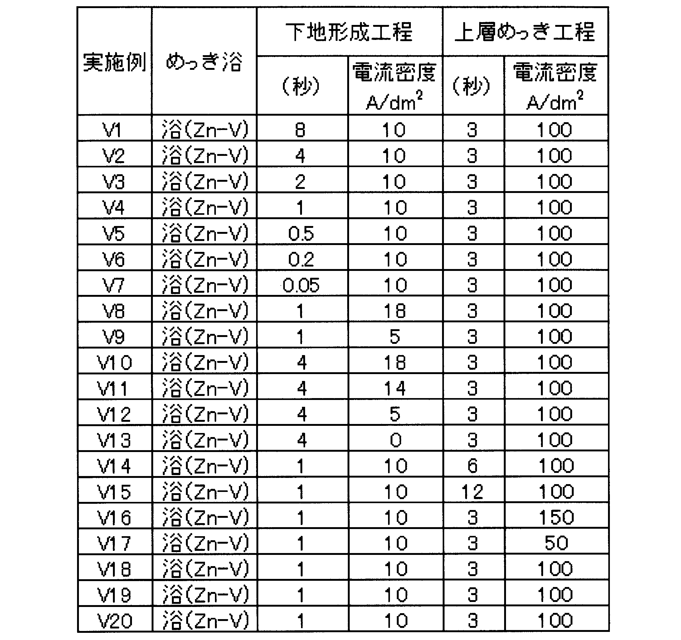
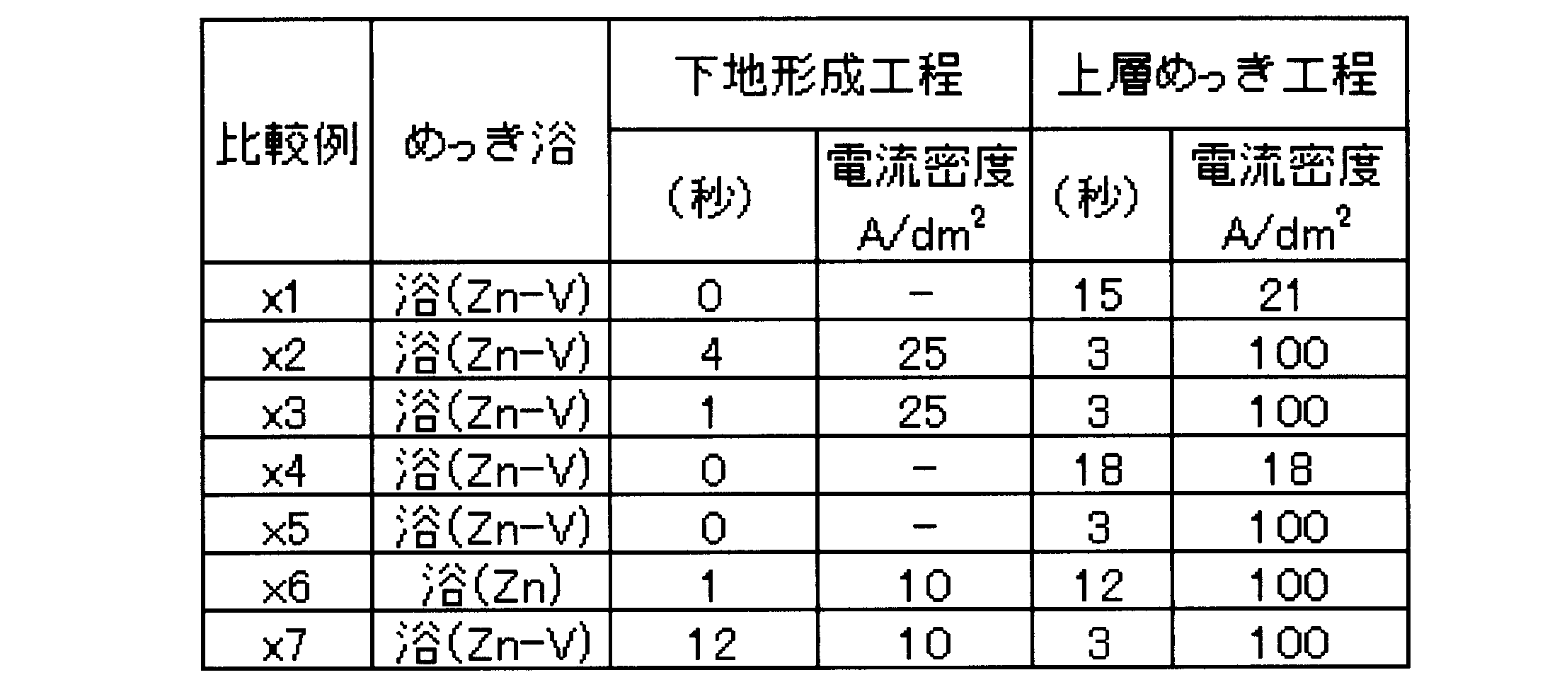
図6は、実施例V4の表面処理鋼板のめっき層の走査型電子顕微鏡(SEM)写真である。図6において、符号56はデンドライト状結晶であり、符号57はデンドライト状結晶間に配置された結晶間充填領域であり、符号58はデンドライト状結晶の表面を覆う表層である。なお、図6に示す写真において、めっき層の表面の白い部分は、めっき層を観察するために蒸着した金膜である。
また、元素分析の結果を用いて、結晶間充填領域のバナジウム量と亜鉛量とのモル比(V/Zn)を算出した。
その結果を表4及び表5に示す。
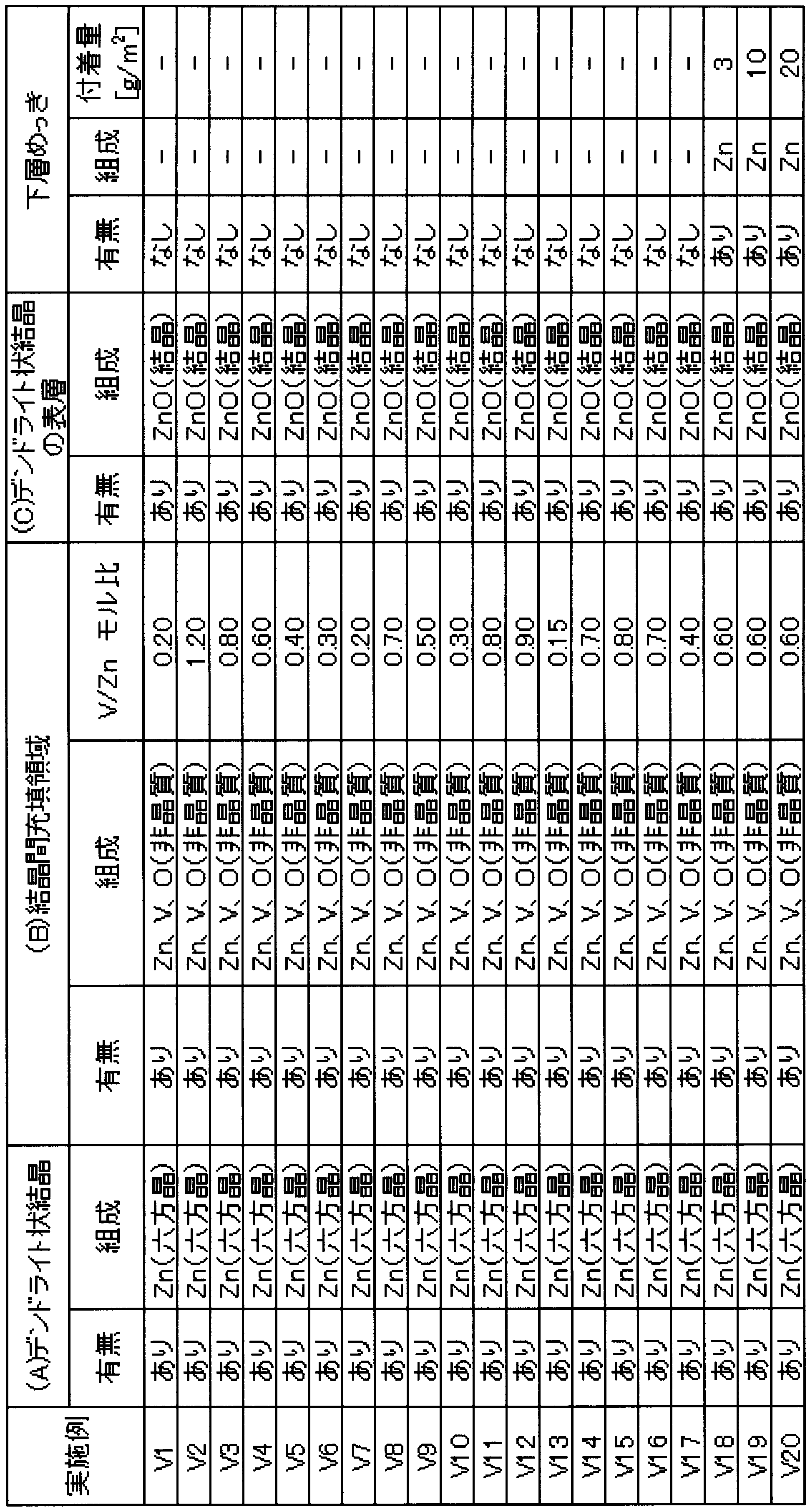

図8は、実施例V4のめっき層の電子線回析像を示した写真である。図8に示す写真に付した符号は、それぞれ図5Bおよび図5Cに示す結晶間充填領域52、デンドライト状結晶53、結晶間充填領域54、デンドライト状結晶の表層55に対応するものである。
図8に示す電子線回析像から、デンドライト状結晶53、デンドライト状結晶の表層55は、結晶構造を有することが分かった。また、結晶間充填領域52、54は結晶構造に起因する回析パターンが得られず、非晶質であることが分かった。
なお、デンドライト状結晶内の不純物を調べたところ、C、Si、S、Fe、Nがそれぞれ0.1~5atm%程度であった。
めっき層の付着量は、蛍光X線装置(リガク社製Simultix14)を用いて検出したZn元素およびV元素の単位面積当たりの合計質量とした。また、めっき層中のバナジウム含有量は、蛍光X線装置により検出されたV元素量を前記付着量で除して百分率で算出した。
表面処理鋼板からから切り出した試験片のエッジおよび裏面をテープシールして、塩水噴霧試験(JIS-Z-2371)を行った。そして、72時間後の非シール部分の白錆発生面積率を目視で観察し、以下の基準で評価した。なお、白錆発生面積率とは、観察部位の面積に対する白錆発生部位の面積の百分率である。
5:白錆発生面積率10%未満、
4:白錆発生面積率10%以上、25%未満
3:白錆発生面積率25%以上、50%未満
2:白錆発生面積率50%以上、75%未満
1:白錆発生面積率75%以上
表面処理鋼板から切り出した試験片に塗料(関西ペイント株式会社製、アミラック♯1000)をバーコート塗布し、140℃で20分間焼付を行い、乾燥膜厚で25μmの皮膜を形成した。その後、塗装した試験片のエッジおよび裏面をテープシールし、表面にNTカッターでXの形になるよう疵を付与した。そして、塩水噴霧試験(JIS-Z-2371)を行い、疵部から赤錆が発生するまでの時間を測定し、以下の基準で評価した。
5:赤錆発生までの時間960時間以上
4:赤錆発生までの時間720時間以上、960時間未満
3:赤錆発生までの時間480時間以上、720時間未満
2:赤錆発生までの時間120時間以上、480時間未満
1:赤錆発生までの時間120時間未満
パウダリング試験には、60°V曲げ金型を用いた。表面処理鋼板から切り出した試験片の評価面が曲げ部の内側となるように、先端の曲率半径が1mmである金型を用いて、60°に曲げ加工し、曲げ部の内側にテープを貼り、テープを引き剥がした。テープと共に剥離しためっき層の剥離状況から、パウダリング性(剥離幅(mm))を評価した。
表面処理鋼板から切り出した試験片に塗料(関西ペイント株式会社製、アミラック♯1000)をバーコート塗布し、140℃で20分間焼付を行い、乾燥膜厚で25μmの皮膜を形成した。得られた塗装板を沸騰水に30分浸漬後、常温の室内に24時間放置した。その後、試験片に対して1mm角100個の碁盤目をNTカッターで切り入れ、これをエリクセン試験機で7mm押し出した後、この押し出し凸部に粘着テープによる剥離テストを行い、塗膜密着性(剥離個数)を評価した。
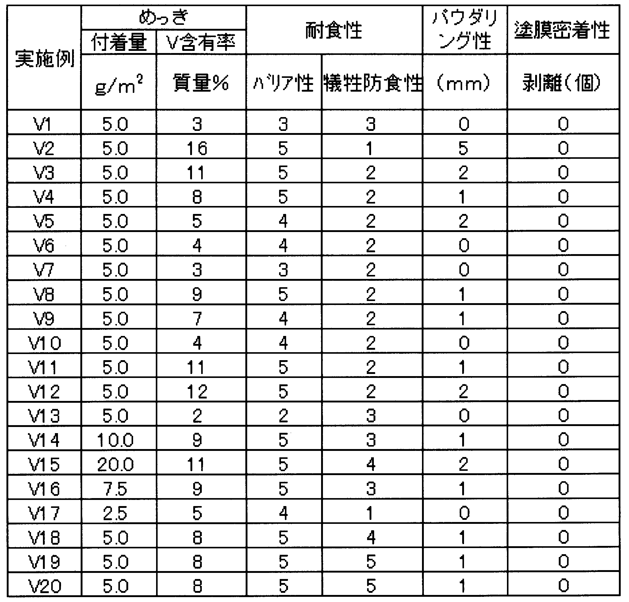
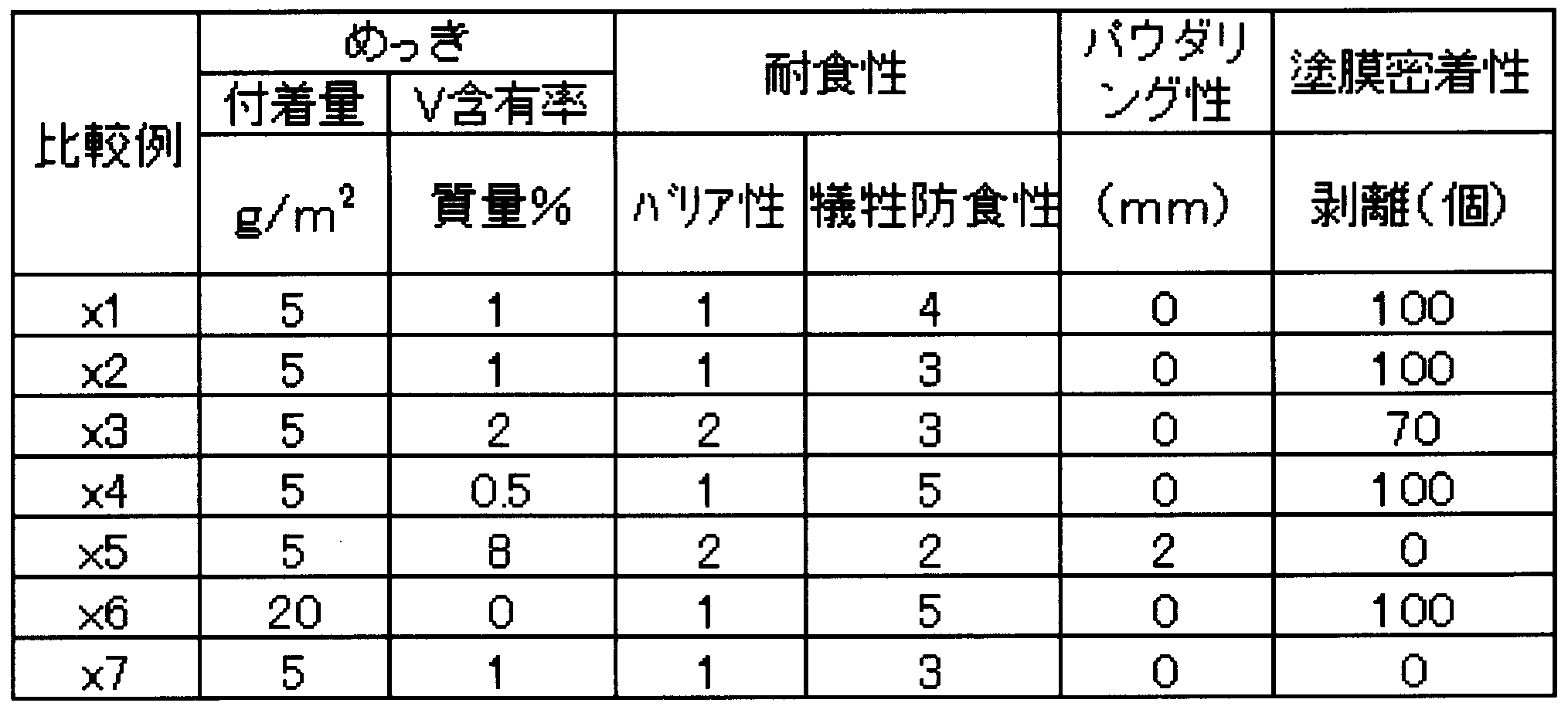
また、下地形成工程における電流密度が0~18A/dm2である実施例V1~実施例V20の表面処理鋼板のめっき層では、下地形成工程における電流密度が25A/dm2である比較例x2及びx3の表面処理鋼板のめっき層とは異なり、結晶間充填領域中のバナジウムと亜鉛とのモル比(V/Zn)が0.10以上2.00以下となり、かつ、電子線回折を行った場合に結晶間充填領域が非晶質の回折パターンを示した。また、バリア性および塗膜密着性がより優れていることが分かった。
皮膜を形成するための塗料組成物は、表8に示す有機樹脂(R)と、りん酸化合物(P)と、カーボンブラック(C)と、有機ケイ素化合物(W)と、フルオロ金属錯体化合物(F)と、イソシアネート化合物(I)と、ポリエチレンワックス(Q)とを、表9および表10に示す含有量(固形分の質量%)で、溶媒である水中に塗料用分散機を用いて撹拌して分散させ、塗料組成物を調製した。

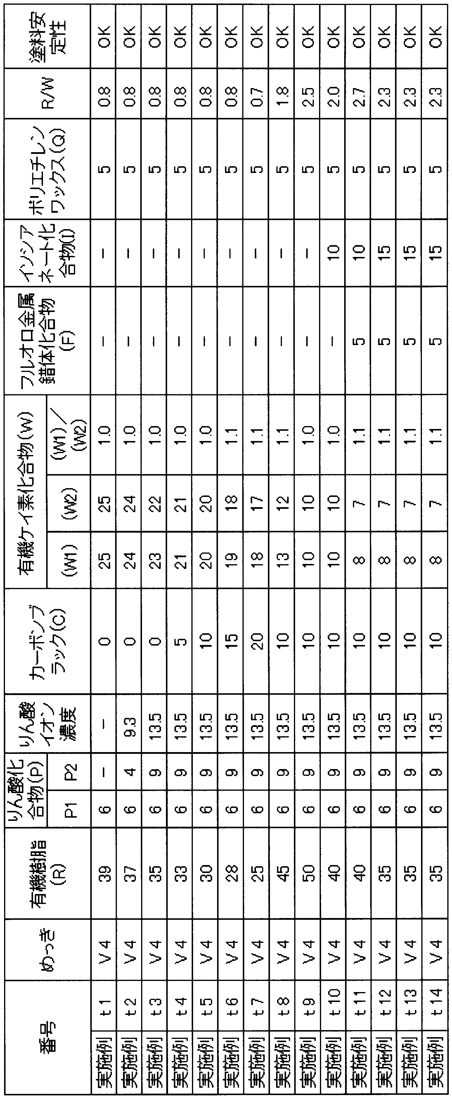

このようにして調製した塗料組成物を、室温で30分撹拌して、沈殿物発生の有無を目視により観察した。
沈殿物が発生しなかったものを塗料安定性「OK」、沈殿物が発生したものを塗料安定性「NG」と評価した。塗料安定性の結果を表9および表10に示す。
まず、表面処理鋼板の表面に、表11および表12に示す膜厚となるように、ロールコーターを用いて塗料組成物を塗布した。その後、塗料組成物を塗布した表面処理鋼板を、板到達温度が150℃となるように加熱して乾燥し、水を用いてスプレー冷却し、皮膜を得た。なお、150℃まで加熱後においてもめっき層中に水和酸化物は存在した。
各項目の評価結果を表11および表12に示す。
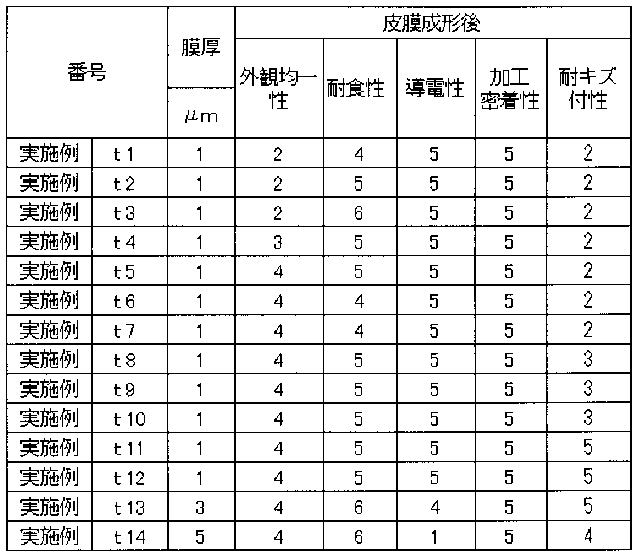

(外観均一性)
コニカミノルタ社製の測色計:CR-400を用いて表面処理鋼板のL*値を測定し、下記の評価基準で評価した。
5:L*値が24未満
4:L*値が24以上、27未満
3:L*値が27以上、28未満
2:L*値が28以上、30未満
1:L*値が30超
表面処理鋼板から切り出した試験片のエッジおよび裏面をテープシールして、塩水噴霧試験(JIS Z 2371)を行った。そして、240時間後の非シール部分の白錆発生面積率を目視で観察し、以下の基準で評価した。白錆発生面積率とは、観察部位の面積に対する白錆発生部位の面積の百分率である。
6:白錆発生率3%未満
5:白錆発生率3%以上、10%未満
4:白錆発生率10%以上、25%未満
3:白錆発生率25%以上、50%未満
2:白錆発生率50%以上、75%未満
1:白錆発生率75%以上
表面処理鋼板から切り出した試験片を用いて、JIS C 2550に規定されている測定方法で、層間抵抗値(Ω・cm2)を測定し、以下の基準にて導電性を評価した。
6:層間抵抗値が1.0Ω・cm2未満
5:層間抵抗値が1.0Ω・cm2以上、1.5Ω・cm2未満
4:層間抵抗値が1.5Ω・cm2以上、2.0Ω・cm2未満
3:層間抵抗値が2.0Ω・cm2以上、2.5Ω・cm2未満
2:層間抵抗値が2.5Ω・cm2以上、3.0Ω・cm2未満
1:層間抵抗値が3.0Ω・cm2以上
表面処理鋼板から切り出した試験片に180°折り曲げ加工を施した後、折り曲げ部の外側に対してテープ剥離試験を実施した。テープ剥離部の外観を拡大率10倍のルーペで観察し、下記の評価基準で評価した。折り曲げ加工は、20℃の雰囲気中で0.5mmのスペーサーを間に挟んで実施した。
5:塗膜に剥離が認められない
4:極一部の塗膜に剥離が認められる(剥離面積≦2%)
3:一部の塗膜に剥離が認められる(2%<剥離面積≦10%)
2:塗膜に剥離が認められる(10%<剥離面積≦20%)
1:塗膜に剥離が認められる(剥離面積>20%)
表面処理鋼板から切り出した供試材を、電気亜鉛めっき鋼板(無処理材)と密着させ、加圧した状態で供試材を90°回転させた。加圧は0.2kg/cm2とし、試験温度は25℃とした。その後、供試材の外観を目視で評価した。
6:キズが全く見えない。
5:細かいキズはあるが、素地の露出なし
4:素地が僅かに露出(露出面積:3%未満)
3:素地が露出(露出面積:3%以上、10%未満)
2:素地が露出(露出面積:10%以上、30%未満)
1:素地が露出(露出面積:30%以上)
図2に示すめっき装置を用いて、以下に示す方法により鋼板の両面にジルコニウムを含むめっき層を有する表面処理鋼板を作成し、評価した。
なお、実施例1と同様の事項についてはその説明を省略する。
表13に示すめっき浴組成、温度、pHのめっき浴を、平均相対流速100m/minで循環させてなる流動状態のめっき浴を用意した。

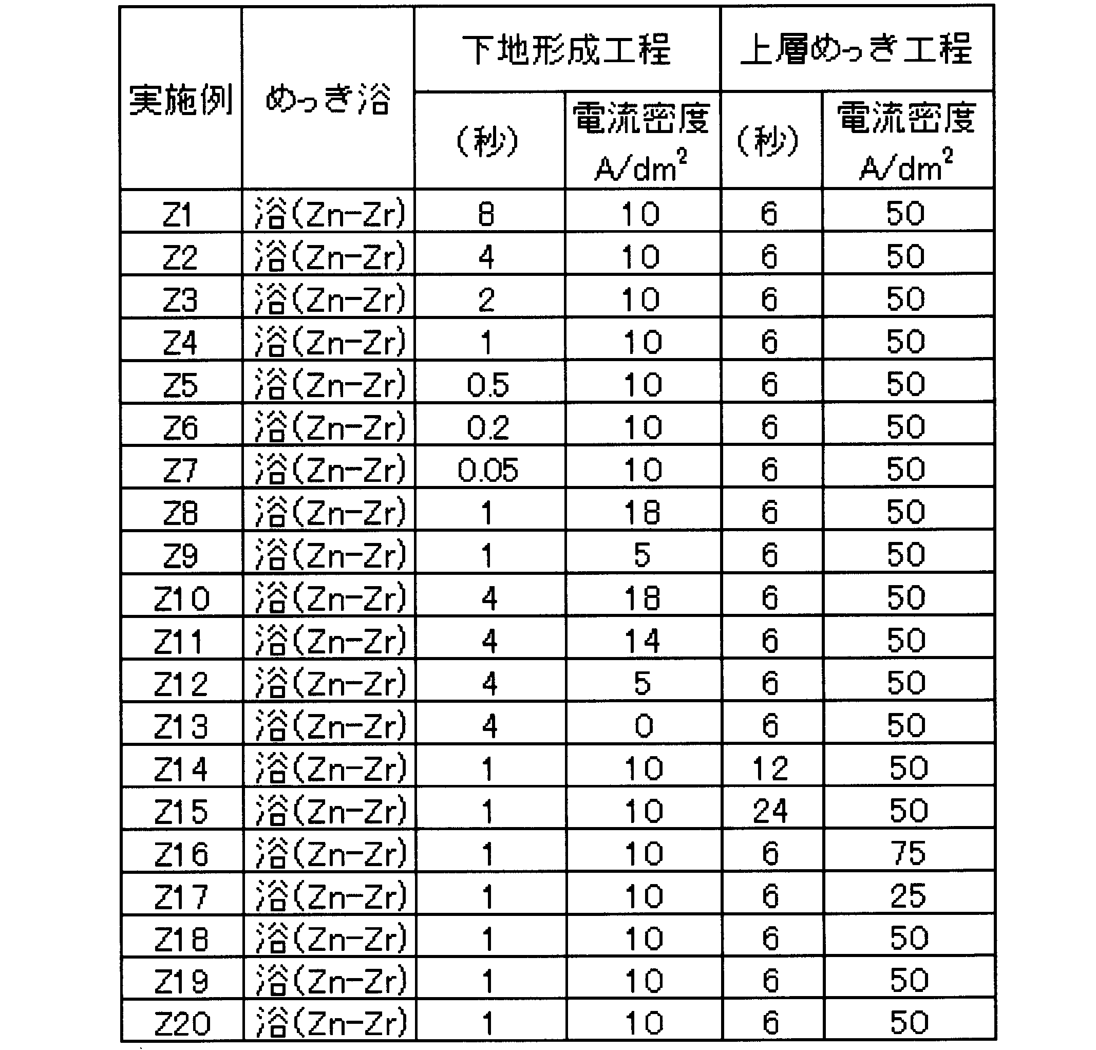
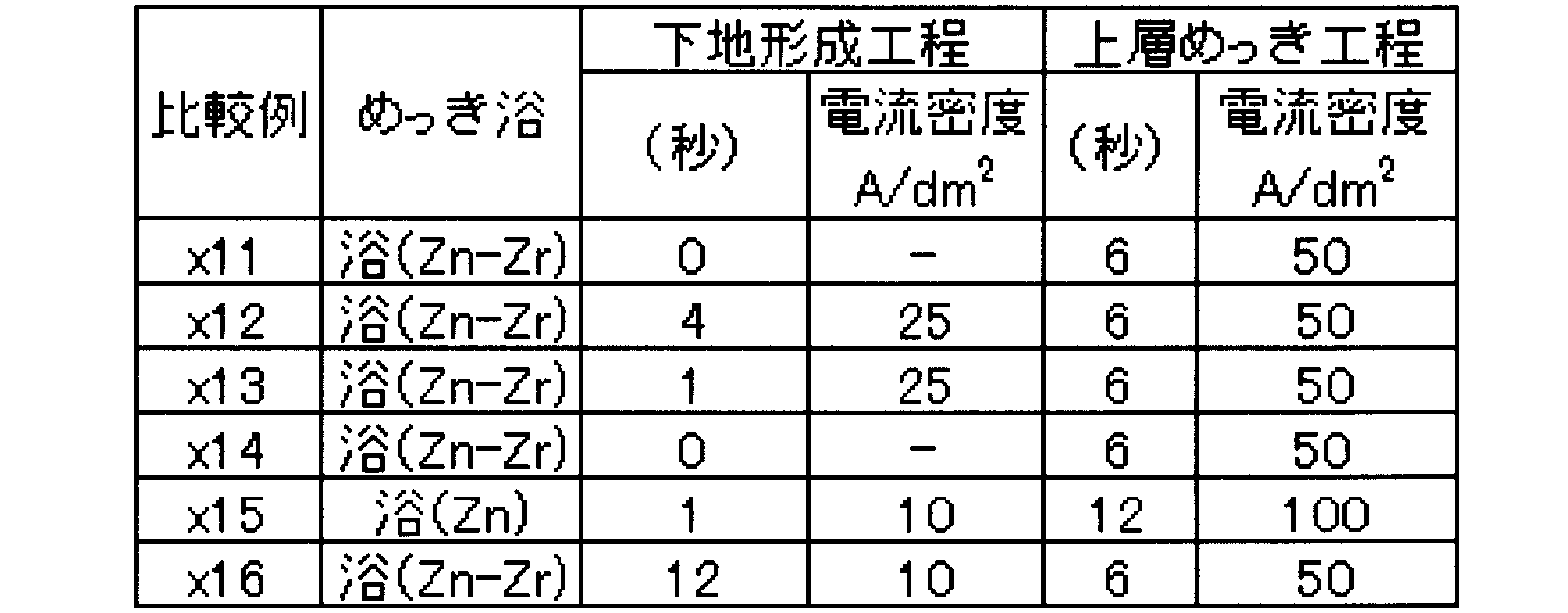
図9に示すように、本実施形態のめっき層には、デンドライト状結晶と、その周囲に形成された結晶間充填領域と、表層部の非晶質層とが形成されていることが判る。デンドライト状結晶は、エネルギー分散型X線分析装置(EDS(日本電子社製(JED-2300T))による元素分析及び電子線回折分析により、金属Znからなることが判明した。また、結晶間充填領域は、酸化ジルコニウム及び水酸化ジルコニウムを含むことが判明した。更に、表層部の非晶質層は、酸化ジルコニウムからなることが判明した。
また、元素分析の結果を用いて、結晶間充填領域のジルコニウム量と亜鉛量とのモル比(Zr/Zn)を算出した。
その結果を表16~表17に示す。
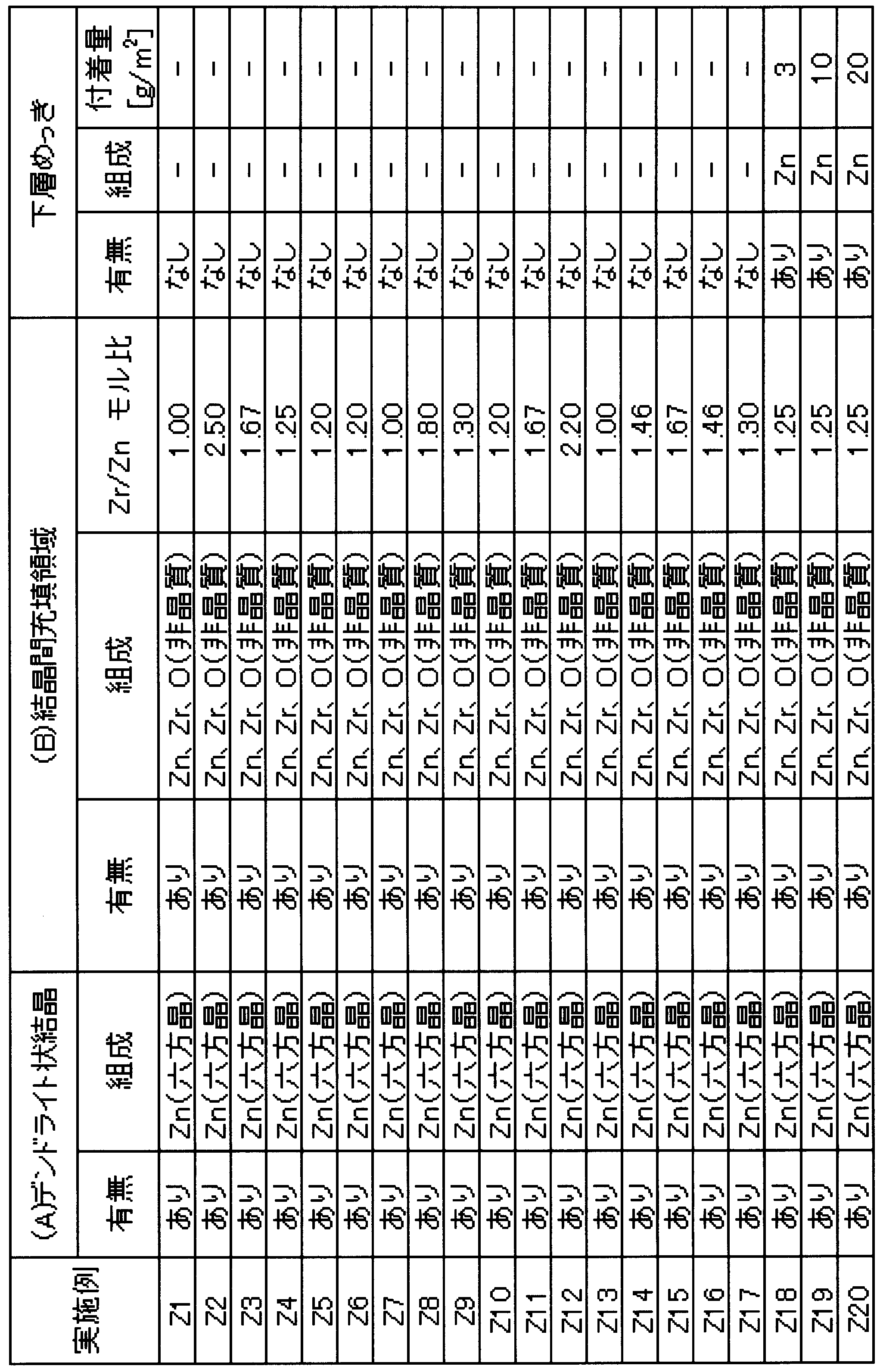
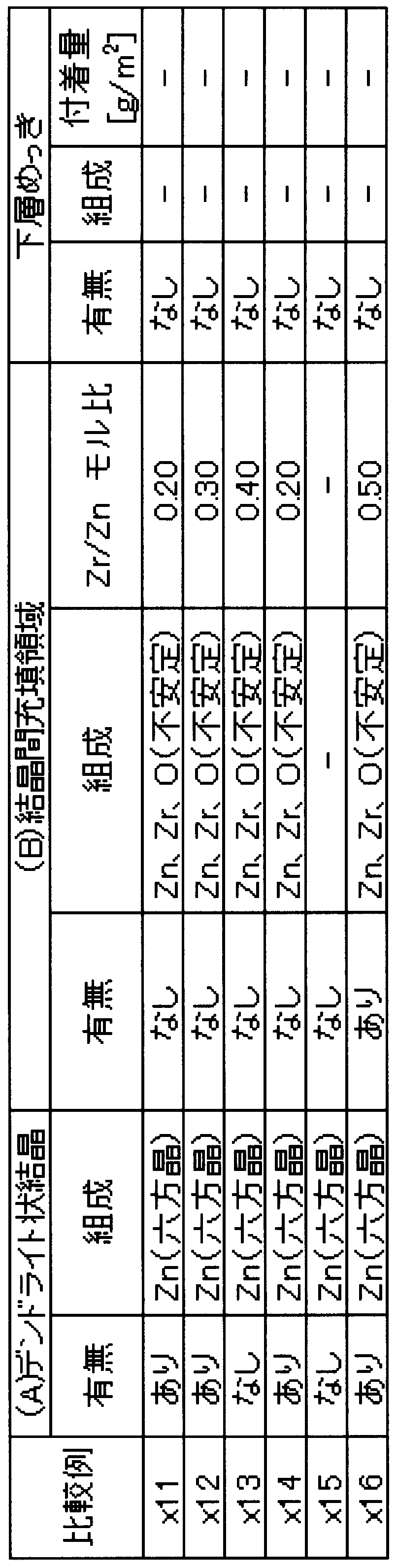
なお、デンドライト状結晶内の不純物を調べたところ、C、Si、S、Fe、Nがそれぞれ0.1~5atm%程度であった。
めっき層の付着量は、蛍光X線装置(リガク社製Simultix14)を用いて検出したZn元素およびZr元素の単位面積当たりの合計質量とした。また、めっき層中のジルコニウム含有量は、蛍光X線装置により検出されたZr元素量を前記付着量で除して百分率で算出した。

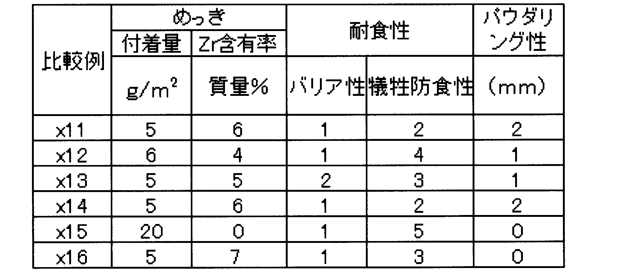
また、下地形成工程における電流密度が0~18A/dm2である実施例Z1~実施例Z20の表面処理鋼板のめっき層では、下地形成工程における電流密度が25A/dm2である比較例x12~x13の表面処理鋼板のめっき層とは異なり、結晶間充填領域中のジルコニウムと亜鉛とのモル比(Zr/Zn)が1.00以上3.00以下となり、かつ、電子線回折を行った場合に結晶間充填領域が非晶質の回折パターンを示した。また、バリア性および塗膜密着性がより優れていることが分かった。
皮膜を形成するための塗料組成物は、表8に示す有機樹脂(R)と、りん酸化合物(P)と、カーボンブラック(C)と、有機ケイ素化合物(W)と、フルオロ金属錯体化合物(F)と、イソシアネート化合物(I)と、ポリエチレンワックス(Q)とを、表20および表21に示す含有量(固形分の質量%)で、溶媒である水中に塗料用分散機を用いて撹拌して分散させ、塗料組成物を調製した。
なお、実施例2と同様の事項については説明を省略する。

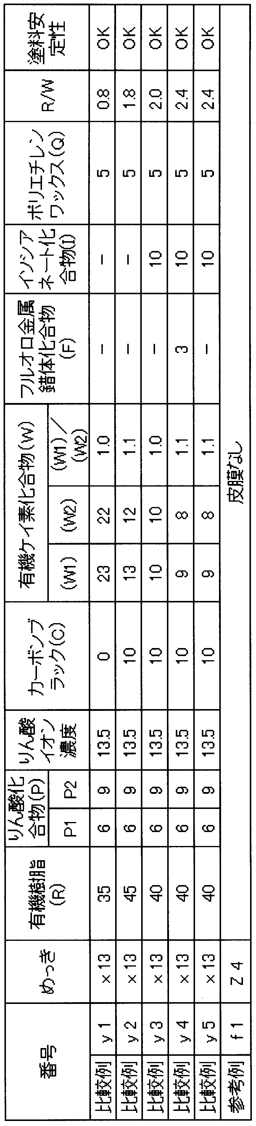
まず、表面処理鋼板の表面に、表22および表23に示す膜厚となるように、ロールコーターを用いて塗料組成物を塗布した。その後、塗料組成物を塗布した表面処理鋼板を、板到達温度が150℃となるように加熱して乾燥し、水を用いてスプレー冷却し、皮膜を得た。なお、150℃まで加熱後においてもめっき層中に水和酸化物は存在した。
各項目の評価結果を表22および表23に示す。


2 めっき浴
2a 上部供給用配管
2b 下部供給用配管
2c、2e 外周分岐路
2d、2f 中間分岐路
3 陽極
3a デンドライト状結晶の内部
3b、55、58 デンドライト状結晶の表層
3c 粒状結晶
4a、5a、4b、5b ロール
6 バナジウム化合物
10、210 表面処理鋼板
20、51、220 下地層
20a ニッケルめっき層
21 めっき槽
21a 上部槽
21b 下部槽
30、230 めっき層
31、53、56、231 デンドライト状結晶
32、52、54、57、232 結晶間充填領域
40、240 表面層
61 電流集中部
62 水素
250 非晶質層
D ロール4a、5aと陽極3との間の間隔
Claims (6)
- 鋼板と;
前記鋼板の片面または両面に形成され、亜鉛とバナジウムまたはジルコニウムとを含むめっき層と;
を備え、
前記めっき層が、
金属亜鉛を含むデンドライト状結晶と;
前記デンドライト状結晶間を充填し、電子線回折を行った場合に非晶質の回折パターンを示す結晶間充填領域と;
を有し、
前記めっき層が前記バナジウムを含む場合に、前記結晶間充填領域が、水和したバナジウム酸化物またはバナジウム水酸化物を含み、
前記めっき層がジルコニウムを含む場合に、前記結晶間充填領域が、水和したジルコニウム酸化物またはジルコニウム水酸化物を含む
ことを特徴とする表面処理鋼板。 - 前記めっき層が前記バナジウムを含む場合に、前記結晶間充填領域中の前記バナジウムと前記亜鉛とのモル比であるV/Znが、0.10以上2.00以下であり、
前記めっき層が前記ジルコニウムを含む場合に、前記結晶間充填領域中の前記ジルコニウムと前記亜鉛とのモル比であるZr/Znが、1.00以上3.00以下である
ことを特徴とする請求項1に記載の表面処理鋼板。 - 前記めっき層が前記バナジウムを含む場合であって、
前記デンドライト状結晶の表層が、亜鉛酸化物または亜鉛水酸化物を含む
ことを特徴とする請求項1または請求項2に記載の表面処理鋼板。 - 前記鋼板と前記めっき層との間に、亜鉛と当該バナジウムとのモル比であるZn/Vが8.00以上である下地めっき層がさらに設けられている
ことを特徴とする請求項1~請求項3のいずれか一項に記載の表面処理鋼板。 - 前記めっき層の表面に、ポリウレタン樹脂と、1~20質量%のカーボンブラックとを有する有機樹脂皮膜をさらに備える
ことを特徴とする、請求項1~請求項4のいずれか一項に記載の表面処理鋼板。 - 請求項1~5のいずれか一項に記載の表面処理鋼板を製造する方法であって、
0.10~4.00mol/lのZn2+イオンと、0.01~2.00mol/lのVイオンまたは0.10~4.00mol/lのZrイオンとを含有するめっき浴を用いて、0~18A/dm2の電流密度で電気めっきを行うことにより、前記鋼板上に水和したバナジウム酸化物、またはバナジウム水酸化物を析出させて凹凸を形成する下地形成工程と;
前記凹凸を形成した前記鋼板に、前記めっき浴を用いて、21~200A/dm2の電流密度で電気めっきを行う上層めっき工程と;
を有する
ことを特徴とする表面処理鋼板の製造方法。
Priority Applications (7)
| Application Number | Priority Date | Filing Date | Title |
|---|---|---|---|
| MYPI2017704407A MY186934A (en) | 2015-06-09 | 2016-06-09 | Surface-treated steel sheet |
| CA2986369A CA2986369A1 (en) | 2015-06-09 | 2016-06-09 | Surface-treated steel sheet |
| KR1020177033913A KR102274990B1 (ko) | 2015-06-09 | 2016-06-09 | 표면 처리 강판 |
| JP2017523694A JP6531825B2 (ja) | 2015-06-09 | 2016-06-09 | 表面処理鋼板 |
| US15/578,145 US20180100244A1 (en) | 2015-06-09 | 2016-06-09 | Surface-treated steel sheet |
| MX2017015441A MX2017015441A (es) | 2015-06-09 | 2016-06-09 | Lamina de acero tratada en la superficie. |
| CN201680031662.2A CN107636207B (zh) | 2015-06-09 | 2016-06-09 | 表面处理钢板 |
Applications Claiming Priority (4)
| Application Number | Priority Date | Filing Date | Title |
|---|---|---|---|
| JP2015116604 | 2015-06-09 | ||
| JP2015-116604 | 2015-06-09 | ||
| JP2015116554 | 2015-06-09 | ||
| JP2015-116554 | 2015-06-09 |
Publications (1)
| Publication Number | Publication Date |
|---|---|
| WO2016199852A1 true WO2016199852A1 (ja) | 2016-12-15 |
Family
ID=57503470
Family Applications (1)
| Application Number | Title | Priority Date | Filing Date |
|---|---|---|---|
| PCT/JP2016/067213 Ceased WO2016199852A1 (ja) | 2015-06-09 | 2016-06-09 | 表面処理鋼板 |
Country Status (9)
| Country | Link |
|---|---|
| US (1) | US20180100244A1 (ja) |
| JP (1) | JP6531825B2 (ja) |
| KR (1) | KR102274990B1 (ja) |
| CN (1) | CN107636207B (ja) |
| CA (1) | CA2986369A1 (ja) |
| MX (1) | MX2017015441A (ja) |
| MY (1) | MY186934A (ja) |
| TW (1) | TWI641728B (ja) |
| WO (1) | WO2016199852A1 (ja) |
Cited By (5)
| Publication number | Priority date | Publication date | Assignee | Title |
|---|---|---|---|---|
| WO2019124521A1 (ja) * | 2017-12-20 | 2019-06-27 | 日本製鉄株式会社 | プレコート鋼板 |
| JP6638867B1 (ja) * | 2018-12-12 | 2020-01-29 | 日本製鉄株式会社 | 被覆鋼板 |
| JP2021123729A (ja) * | 2020-01-31 | 2021-08-30 | 日本製鉄株式会社 | 表面処理めっき鋼板およびそれに用いるめっき鋼板、ならびに表面処理めっき鋼板の製造方法 |
| JP2021123728A (ja) * | 2020-01-31 | 2021-08-30 | 日本製鉄株式会社 | めっき液の製造方法およびめっき液、ならびにめっき鋼板の製造方法およびめっき鋼板 |
| WO2025109918A1 (ja) * | 2023-11-22 | 2025-05-30 | 東洋鋼鈑株式会社 | 表面処理亜鉛めっき鋼板、樹脂フィルム被覆鋼板、建築用パネル、表面処理亜鉛めっき鋼板の製造方法、及び樹脂フィルム被覆鋼板の製造方法 |
Families Citing this family (4)
| Publication number | Priority date | Publication date | Assignee | Title |
|---|---|---|---|---|
| MX2019014874A (es) | 2017-06-16 | 2020-02-07 | Nippon Steel Corp | Acero enchapado. |
| DE102019203803A1 (de) | 2019-03-20 | 2020-09-24 | Robert Bosch Gmbh | Zündkerzengehäuse mit galvanischer Nickel- und Zink-haltiger Schutzschicht und einer Silizium-haltigen Versiegelungsschicht, sowie eine Zündkerze mit diesem Gehäuse und Herstellungsverfahren für dieses Gehäuse |
| DE102019203805A1 (de) * | 2019-03-20 | 2020-09-24 | Robert Bosch Gmbh | Zündkerzengehäuse mit galvanischer Zink-haltiger Schutzschicht und einer Silizium-haltigen Versiegelungsschicht, sowie eine Zündkerze mit diesem Gehäuse und Herstellungsverfahren für dieses Gehäuse |
| CN110512246B (zh) * | 2019-09-29 | 2020-11-03 | 太仓陶氏电气有限公司 | 一种用于电子元器件散热系统的泡沫金属的制备工艺 |
Citations (4)
| Publication number | Priority date | Publication date | Assignee | Title |
|---|---|---|---|---|
| JPH11343559A (ja) * | 1998-05-30 | 1999-12-14 | Nkk Corp | 耐クラック性及び耐食性に優れた溶融Al−Zn系合金めっき鋼板 |
| JP2013108183A (ja) * | 2011-03-29 | 2013-06-06 | Nippon Steel & Sumitomo Metal Corp | 表面処理鋼板の製造方法 |
| JP2014114503A (ja) * | 2012-11-15 | 2014-06-26 | Jfe Steel Corp | 亜鉛系電気めっき鋼板およびその製造方法 |
| JP2014234520A (ja) * | 2013-05-30 | 2014-12-15 | Jfeスチール株式会社 | 亜鉛系電気めっき鋼板の製造方法 |
Family Cites Families (6)
| Publication number | Priority date | Publication date | Assignee | Title |
|---|---|---|---|---|
| US7144637B2 (en) * | 2004-07-12 | 2006-12-05 | Thomae Kurt J | Multilayer, corrosion-resistant finish and method |
| JP5042555B2 (ja) * | 2006-08-03 | 2012-10-03 | 新日本製鐵株式会社 | 薄膜一次防錆被覆層を有する表面導電性に優れた亜鉛系めっき鋼板とその製造方法 |
| KR101046301B1 (ko) * | 2009-09-23 | 2011-07-04 | 주식회사 엠.이.시 | 니켈플래쉬 도금용액, 전기아연강판 및 이의 제조방법 |
| KR101860071B1 (ko) * | 2009-11-20 | 2018-06-27 | 도요 고한 가부시키가이샤 | 커버 부재용 표면처리강판의 제조방법 |
| JP2011111633A (ja) | 2009-11-24 | 2011-06-09 | Jfe Steel Corp | 亜鉛系複合電気めっき鋼板の製造方法 |
| JP2013185199A (ja) | 2012-03-07 | 2013-09-19 | Jfe Steel Corp | 亜鉛系電気めっき鋼板およびその製造方法 |
-
2016
- 2016-06-09 JP JP2017523694A patent/JP6531825B2/ja active Active
- 2016-06-09 WO PCT/JP2016/067213 patent/WO2016199852A1/ja not_active Ceased
- 2016-06-09 CA CA2986369A patent/CA2986369A1/en not_active Abandoned
- 2016-06-09 MX MX2017015441A patent/MX2017015441A/es unknown
- 2016-06-09 MY MYPI2017704407A patent/MY186934A/en unknown
- 2016-06-09 CN CN201680031662.2A patent/CN107636207B/zh active Active
- 2016-06-09 US US15/578,145 patent/US20180100244A1/en not_active Abandoned
- 2016-06-09 KR KR1020177033913A patent/KR102274990B1/ko active Active
- 2016-06-13 TW TW105118388A patent/TWI641728B/zh active
Patent Citations (4)
| Publication number | Priority date | Publication date | Assignee | Title |
|---|---|---|---|---|
| JPH11343559A (ja) * | 1998-05-30 | 1999-12-14 | Nkk Corp | 耐クラック性及び耐食性に優れた溶融Al−Zn系合金めっき鋼板 |
| JP2013108183A (ja) * | 2011-03-29 | 2013-06-06 | Nippon Steel & Sumitomo Metal Corp | 表面処理鋼板の製造方法 |
| JP2014114503A (ja) * | 2012-11-15 | 2014-06-26 | Jfe Steel Corp | 亜鉛系電気めっき鋼板およびその製造方法 |
| JP2014234520A (ja) * | 2013-05-30 | 2014-12-15 | Jfeスチール株式会社 | 亜鉛系電気めっき鋼板の製造方法 |
Cited By (9)
| Publication number | Priority date | Publication date | Assignee | Title |
|---|---|---|---|---|
| WO2019124521A1 (ja) * | 2017-12-20 | 2019-06-27 | 日本製鉄株式会社 | プレコート鋼板 |
| JPWO2019124521A1 (ja) * | 2017-12-20 | 2020-11-19 | 日本製鉄株式会社 | プレコート鋼板 |
| JP6638867B1 (ja) * | 2018-12-12 | 2020-01-29 | 日本製鉄株式会社 | 被覆鋼板 |
| WO2020121431A1 (ja) * | 2018-12-12 | 2020-06-18 | 日本製鉄株式会社 | 被覆鋼板 |
| JP2021123729A (ja) * | 2020-01-31 | 2021-08-30 | 日本製鉄株式会社 | 表面処理めっき鋼板およびそれに用いるめっき鋼板、ならびに表面処理めっき鋼板の製造方法 |
| JP2021123728A (ja) * | 2020-01-31 | 2021-08-30 | 日本製鉄株式会社 | めっき液の製造方法およびめっき液、ならびにめっき鋼板の製造方法およびめっき鋼板 |
| JP7364896B2 (ja) | 2020-01-31 | 2023-10-19 | 日本製鉄株式会社 | 表面処理めっき鋼板およびそれに用いるめっき鋼板、ならびに表面処理めっき鋼板の製造方法 |
| JP7397305B2 (ja) | 2020-01-31 | 2023-12-13 | 日本製鉄株式会社 | めっき液の製造方法およびめっき液、ならびにめっき鋼板の製造方法 |
| WO2025109918A1 (ja) * | 2023-11-22 | 2025-05-30 | 東洋鋼鈑株式会社 | 表面処理亜鉛めっき鋼板、樹脂フィルム被覆鋼板、建築用パネル、表面処理亜鉛めっき鋼板の製造方法、及び樹脂フィルム被覆鋼板の製造方法 |
Also Published As
| Publication number | Publication date |
|---|---|
| MY186934A (en) | 2021-08-26 |
| KR20180015133A (ko) | 2018-02-12 |
| CA2986369A1 (en) | 2016-12-15 |
| JPWO2016199852A1 (ja) | 2018-01-25 |
| CN107636207B (zh) | 2020-04-28 |
| TW201710562A (zh) | 2017-03-16 |
| TWI641728B (zh) | 2018-11-21 |
| US20180100244A1 (en) | 2018-04-12 |
| CN107636207A (zh) | 2018-01-26 |
| JP6531825B2 (ja) | 2019-06-19 |
| MX2017015441A (es) | 2018-03-08 |
| KR102274990B1 (ko) | 2021-07-09 |
Similar Documents
| Publication | Publication Date | Title |
|---|---|---|
| JP6531825B2 (ja) | 表面処理鋼板 | |
| EP2280094B1 (en) | Metallic material and manufacturing method thereof | |
| US10415148B2 (en) | Passivation of micro-discontinuous chromium deposited from a trivalent electrolyte | |
| WO2012036204A1 (ja) | 容器用鋼板 | |
| US9157165B2 (en) | Method of production of chemically treated steel sheet | |
| TW202227667A (zh) | 表面處理鋼板及其製造方法 | |
| EP4219795A1 (en) | Surface-treated steel sheet and production method therefor | |
| CN101970725A (zh) | 具有薄膜一次防锈被覆层的表面导电性优良的锌系镀覆钢板及其制造方法 | |
| JP5334499B2 (ja) | 塗装密着性に優れた表面処理金属板およびその製造方法 | |
| JP6112268B1 (ja) | 表面処理鋼板 | |
| JP5130080B2 (ja) | リン酸塩処理電気亜鉛めっき鋼板 | |
| TW202227671A (zh) | 表面處理鋼板及其製造方法 | |
| JP5812041B2 (ja) | 亜鉛系電気めっき鋼板の製造方法 | |
| JP2008174819A (ja) | 塗膜形成方法 | |
| KR20170087545A (ko) | 표면처리강판 제조방법 | |
| EP4212650A1 (en) | Surface-treated steel sheet and production method therefor | |
| JP2010022911A (ja) | プレコート鋼板の製造方法およびその製造方法により製造されたプレコート鋼板。 | |
| JP5119864B2 (ja) | リン酸塩処理亜鉛系めっき鋼板及びその製造方法 | |
| JP5607575B2 (ja) | 塗膜形成方法及び被覆鋼板 | |
| JP6515383B2 (ja) | 黒色亜鉛合金めっき鋼板とその製造方法 | |
| US20110104514A1 (en) | Method for producing tinned steel sheet and tinned steel sheet | |
| Chen et al. | Preparation and characterization of high electrical conductivity and corrosion resistant black passivation film on Zn-Ni alloy coating of AA2024 substrates | |
| JP4661627B2 (ja) | 表面処理亜鉛系めっき金属材及びその製造方法 | |
| Jayaramaiah et al. | Co-precipitation synthesis of Cu 2 V 2 O 7 nanoparticles and electrochemical investigation of the corrosion resistance of Zn–Cu 2 V 2 O 7 composite coatings on mild steel in 3.5 wt% NaCl and 0.1 M HCl solutions | |
| WO2025079688A1 (ja) | 溶融めっき鋼材 |
Legal Events
| Date | Code | Title | Description |
|---|---|---|---|
| 121 | Ep: the epo has been informed by wipo that ep was designated in this application |
Ref document number: 16807558 Country of ref document: EP Kind code of ref document: A1 |
|
| DPE1 | Request for preliminary examination filed after expiration of 19th month from priority date (pct application filed from 20040101) | ||
| ENP | Entry into the national phase |
Ref document number: 2017523694 Country of ref document: JP Kind code of ref document: A |
|
| ENP | Entry into the national phase |
Ref document number: 2986369 Country of ref document: CA |
|
| ENP | Entry into the national phase |
Ref document number: 20177033913 Country of ref document: KR Kind code of ref document: A |
|
| WWE | Wipo information: entry into national phase |
Ref document number: 15578145 Country of ref document: US |
|
| WWE | Wipo information: entry into national phase |
Ref document number: MX/A/2017/015441 Country of ref document: MX |
|
| NENP | Non-entry into the national phase |
Ref country code: DE |
|
| 122 | Ep: pct application non-entry in european phase |
Ref document number: 16807558 Country of ref document: EP Kind code of ref document: A1 |