WO2016195103A1 - 弾性クローラ - Google Patents
弾性クローラ Download PDFInfo
- Publication number
- WO2016195103A1 WO2016195103A1 PCT/JP2016/066691 JP2016066691W WO2016195103A1 WO 2016195103 A1 WO2016195103 A1 WO 2016195103A1 JP 2016066691 W JP2016066691 W JP 2016066691W WO 2016195103 A1 WO2016195103 A1 WO 2016195103A1
- Authority
- WO
- WIPO (PCT)
- Prior art keywords
- cord
- layer
- crawler
- elastic
- code
- Prior art date
- Legal status (The legal status is an assumption and is not a legal conclusion. Google has not performed a legal analysis and makes no representation as to the accuracy of the status listed.)
- Ceased
Links
Images



Classifications
-
- B—PERFORMING OPERATIONS; TRANSPORTING
- B62—LAND VEHICLES FOR TRAVELLING OTHERWISE THAN ON RAILS
- B62D—MOTOR VEHICLES; TRAILERS
- B62D55/00—Endless track vehicles
- B62D55/08—Endless track units; Parts thereof
- B62D55/18—Tracks
- B62D55/24—Tracks of continuously flexible type, e.g. rubber belts
- B62D55/244—Moulded in one piece, with either smooth surfaces or surfaces having projections, e.g. incorporating reinforcing elements
-
- B—PERFORMING OPERATIONS; TRANSPORTING
- B62—LAND VEHICLES FOR TRAVELLING OTHERWISE THAN ON RAILS
- B62D—MOTOR VEHICLES; TRAILERS
- B62D55/00—Endless track vehicles
- B62D55/08—Endless track units; Parts thereof
- B62D55/18—Tracks
- B62D55/24—Tracks of continuously flexible type, e.g. rubber belts
- B62D55/253—Tracks of continuously flexible type, e.g. rubber belts having elements interconnected by one or more cables or like elements
Definitions
- One embodiment of the present invention relates to an elastic crawler.
- Japanese Patent Application Laid-Open No. 2008-166862 discloses a rubber crawler in which a cord is disposed inside a crawler body.
- the elastic crawler is distorted inside the crawler due to winding around the sprocket or idler or pressing from the wheel.
- the cord layers embedded in the elastic crawler may be separated from each other.
- An object of one embodiment of the present invention is to suppress separation of cord layers embedded in an elastic crawler in consideration of the above fact.
- the elastic crawler according to the first aspect of the present invention is formed by an elastic crawler body formed endlessly by an elastic body, a plurality of cords arranged at intervals and covered with an elastic body, and the elastic crawler main body
- a plurality of cord layers embedded in the cord layers, and the cords included in the cord layers adjacent to each other are arranged so as to intersect each other when viewed from the thickness direction of the elastic crawler main body, and the elastic crawler main body
- at least one pair of adjacent code layers has a total area of a portion where the codes included in each layer of the adjacent code layers overlap each other when viewed in the thickness direction.
- the areas of the cord layers where the cords are not arranged are smaller than the total area of the overlapping portions when viewed from the thickness direction.
- each cord layer of the elastic crawler an area where no cord is arranged is filled with an elastic body.
- regions where the cords of the respective layers are not arranged overlap each other continuously over the two adjacent cord layers.
- the elastic body is filled.
- two adjacent code layers are connected by an elastic body penetrating the two adjacent layers in a portion where the areas where the codes of the respective layers are not arranged overlap each other.
- the elastic crawler according to the first aspect of the present invention has an elastic body in at least one pair of adjacent two cord layers as viewed from the thickness direction of the elastic crawler main body in at least a part of the elastic crawler main body.
- the total area of the portions that are connected through is larger than the total area of the portions where the cords of the two layers overlap.
- the elastic crawler according to the second aspect of the present invention is formed by covering an elastic crawler body formed endlessly with an elastic body, a plurality of cords arranged at intervals and covered with an elastic body, A plurality of cord layers embedded in the cord layers, and the cords included in the cord layers adjacent to each other are arranged so as to intersect each other when viewed from the thickness direction of the elastic crawler main body, and the elastic crawler main body In at least some of the regions, the cords included in each layer of at least one pair of adjacent cord layers satisfy the following formula (1).
- K a is the diameter ( ⁇ a ) of one cord selected from a plurality of cords included in the a-th layer from the inner peripheral surface side of the elastic crawler body, and the one The ratio ( ⁇ a / ( ⁇ a ) where the pitch of the cord ( ⁇ a + D a (D a represents the inter-cord distance between the other cord adjacent to the one cord in the a layer and the one cord)) + D a )).
- “1-K a ” represents a ratio (D a / ( ⁇ a + D a )) between the distance between cords (D a ) and the pitch ( ⁇ a + D a ) of the one cord.
- “K a + 1 ” is the diameter ( ⁇ a + 1 ) of one cord selected from a plurality of cords included in the (a + 1) th layer from the inner peripheral surface side of the elastic crawler body and the pitch ( ⁇ of the one cord) ratio ( ⁇ a + 1 / ( ⁇ a + 1 + D a + 1 )) with a + 1 + D a + 1 (D a + 1 represents the inter-code distance between the other code adjacent to the one code and the one code in the (a + 1) layer) ).
- “1-K a + 1 ” represents the ratio (D a + 1 / ( ⁇ a + 1 + D a + 1 )) between the inter-code distance (D a + 1 ) and the pitch ( ⁇ a + 1 + D a + 1 ) of the one code.
- a is 1 ⁇ a ⁇ X ⁇ 1 (X ⁇ 2, X represents the number of code layers).
- the one code selected from the plurality of codes included in the a layer or the (a + 1) layer is one code arbitrarily selected from the plurality of codes included in the a layer or the (a + 1) layer. Means that.
- the a layer and the (a + 1) layer are the a-th and (a + 1) -th code layers counted from the inner peripheral surface side of the elastic crawler body, and the a-layer and the (a + 1) -layer are layers adjacent to each other. is there.
- a plurality of cord layers are embedded in the elastic crawler body, and the cords respectively included in the adjacent cord layers are arranged so as to intersect each other as viewed from the thickness direction of the elastic crawler body.
- the area of the portion where the cords overlap between adjacent layers is adjacent to these cords. It indicates that the area is smaller than the area of the overlapping area.
- the portion where the adjacent two-layer cords are not arranged is overlapped with the elastic body continuously over the two cord layers. That is, in the portion where the adjacent two-layer cords are not arranged, the two adjacent cord layers are connected by the elastic body penetrating the two layers. On the other hand, in the adjacent two cord layers, the portions where the cords overlap with each other cannot be connected through the two cord layers because the elastic body is divided by the cord.
- the relationship of the formula (1) is such that at least a part of at least one pair of adjacent cord layers among a plurality of cord layers embedded in the elastic crawler body has three or more layers. It holds in the area. For this reason, in at least a partial region of the elastic crawler main body, the total area of the portions where at least one pair of adjacent cord layers penetrates and is connected by the elastic body when viewed in the thickness direction of the elastic crawler main body is the two layers. This is larger than the total area of the portions where the codes overlap.
- the elastic crawler according to a third aspect of the present invention is the elastic crawler according to the second aspect, wherein the plurality of cord layers include a main cord layer and a cross cord layer adjacent to the main cord layer.
- the plurality of cord layers include a main cord layer and a cross cord layer adjacent to the main cord layer.
- the main cord included in the main cord layer and the intersecting cord included in the intersecting cord layer satisfy the formula (1).
- the area of the portion connected by the elastic body that passes through the main cord layer and the cross cord layer adjacent to the main cord layer is the cord of the two layers. It is larger than the area of the overlapping part. Therefore, peeling between the main cord layer embedded in the elastic crawler and the cross cord layers adjacent to the main cord layer can be suppressed.
- the pitch of the intersecting cord is larger than twice the diameter of the intersecting cord.
- the pitch of the main cord can be reduced while satisfying the formula (1) by forming the pitch of the intersecting cord large.
- the cords included in all the adjacent cord layers satisfy the formula (1).
- the area of the portion where all the two adjacent cord layers are connected through the elastic body is the portion where the two cords overlap each other. Is larger than the area.
- the elastic crawler according to a sixth aspect of the present invention is the elastic crawler according to any one of the second to fifth aspects, wherein all the code layers are penetrated by the elastic body when viewed from the thickness direction of the elastic crawler body. It has a part to be connected.
- all cord layers have a portion that penetrates and is connected by an elastic body. Therefore, it is possible to enhance the effect of suppressing the separation of the cord layers between the cord layers embedded in the elastic crawler.
- the elastic crawler according to the seventh aspect of the present invention is the elastic crawler according to any one of the second to sixth aspects, wherein the cords satisfying the formula (1) when viewed from the thickness direction of the elastic crawler body are: The following formula (2) is satisfied.
- the area of the part where all the cord layers are penetrated and connected by the elastic body is larger than the area of the part where two adjacent adjacent cords overlap. Is also big.
- the elastic crawler according to the eighth aspect of the present invention is the elastic crawler according to any one of the second aspect to the seventh aspect, wherein a protrusion is provided on the inner peripheral surface of the elastic crawler body at intervals in the crawler circumferential direction. A part of the area is an area outside the protrusion in the crawler width direction.
- protrusions are provided on the inner peripheral surface of the elastic crawler body at intervals in the crawler circumferential direction, and are arbitrarily adjacent to each other on the outer side in the crawler width direction of the protrusions as viewed from the thickness direction of the elastic crawler body.
- the area of the portion where the two cord layers are connected by the elastic body is larger than the area of the portion where the two cords overlap.
- the elastic crawler according to one aspect of the present invention, it is possible to suppress separation of the code layers embedded in the elastic crawler.
- FIG. 1 is a partially cut plan view of an elastic crawler according to a first embodiment of the present invention. It is a partial enlarged plan view of an elastic crawler concerning a 1st embodiment of the present invention. It is a partial enlarged plan view of an elastic crawler concerning a 1st embodiment of the present invention. It is a partial enlarged plan view of an elastic crawler concerning a 2nd embodiment of the present invention. It is the elements on larger scale of the elastic crawler concerning other embodiments of the present invention.
- the rubber crawler 80 in this embodiment is an endless track that is used by being wound around the sprocket 91 and the idler 92 so as to surround the sprocket 91, the idler 92, the plurality of wheels 90, and the like.
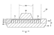
- FIG. 2 is a cross-sectional view along an axis perpendicular to the axis of the crawler circumferential direction of the rubber crawler 80 of the first embodiment.
- the crawler circumferential direction is a direction along the rotation direction of the rubber crawler 80, and can also be referred to as a longitudinal direction.
- the crawler width direction is a direction orthogonal to the rotation direction of the rubber crawler 80, and the crawler thickness direction is a direction when the rubber crawler 80 is viewed from the inner peripheral surface side or the outer peripheral surface side.
- the crawler width direction is indicated by arrow W
- the crawler thickness direction is indicated by arrow D
- the crawler width direction is indicated by arrow W
- the crawler circumferential direction is indicated by arrow L.
- the rubber crawler 80 includes a rubber crawler main body 82, a protrusion 50, and a lug 60 that are endlessly formed of rubber as an example of an elastic body.
- the rubber crawler body 82 is an example of an elastic crawler body in the present embodiment.
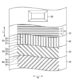
- a 0 degree cord layer 10 In the rubber crawler body 82, a 0 degree cord layer 10, a main cord layer 20, a bias cord layer 30, and a bias cord layer 40 are laminated in this order from the inner peripheral surface side (the upper side in FIG. 2).
- the protrusions 50 are provided at the center of the inner peripheral surface of the rubber crawler body 82 with a constant pitch (interval) in the circumferential direction of the rubber crawler 80.
- the protrusion 50 is engaged with the sprocket 91 to transmit the driving force to the rubber crawler 80. Further, in the rubber crawler main body 82, the outer side of the protrusion 50 in the crawler width direction, in other words, the left and right inner peripheral surfaces 71 and 72 are the running surfaces of the wheel 90 indicated by a two-dot chain line.
- the lugs 60 are provided on the outer peripheral surface of the rubber crawler main body 82 so as to protrude with a constant pitch in the circumferential direction of the rubber crawler 80.
- the 0 degree cord layer 10 has an endless belt shape, and the 0 degree cord 11 embedded in a direction perpendicular to the direction of the main cord 21 to be described later is a crawler of the rubber crawler body 82. It is embedded at equal intervals in the circumferential direction.
- the 0 degree cord 11 is a reinforcing steel cord for increasing the rigidity in the width direction of the rubber crawler 80, and is configured by twisting a plurality of strands.
- the strand is formed by twisting a plurality of filaments.
- the rubber crawler body 82 is embedded along the crawler width direction of the rubber crawler 80. For this reason, the rubber crawler main body 82 is hardly deformed in the crawler width direction.
- the 0 degree code layer 11 is an example of a cross code layer in the present embodiment.
- a main code layer 20 is disposed on the outer peripheral surface side of the 0-degree code layer 10.
- the main cord layer 20 has an endless belt shape, and the main cord 21 is embedded in the crawler width direction of the rubber crawler body 82 at equal intervals.
- the main cord 21 is spirally wound in the crawler circumferential direction of the rubber crawler 80 and embedded in the rubber crawler main body 82. As a result, the main cord 21 has the same distance in the crawler width direction over the entire circumference of the rubber crawler 80 in the crawler circumferential direction.
- the main cord 21 is a steel cord embedded to enhance the tensile strength of the rubber crawler 80 in the crawler circumferential direction, and is configured by twisting a plurality of strands.
- the strand is formed by twisting a plurality of filaments. For this reason, the tensile strength of the rubber crawler main body 82 in the crawler circumferential direction is increased.
- a bias code layer 30 is disposed on the outer peripheral surface side of the main code layer 20.
- the bias cord layer 30 has an endless belt shape, and the bias cord 31 is configured to be embedded at equal intervals over the crawler width direction of the rubber crawler body 82. Further, it is configured to be embedded at equal intervals in the crawler circumferential direction.
- the bias cord 31 extends obliquely with respect to the crawler circumferential direction and is arranged in parallel, and intersects with the main cord 21 and a bias cord 41 described later as viewed from the inner circumferential surface of the rubber crawler 80.
- the bias cord 31 and the bias cord 41 are inclined in directions opposite to each other with respect to the crawler circumferential direction.
- seeing from the inner peripheral surface of the rubber crawler 80 is an aspect in which the rubber crawler main body 82 is seen from the thickness direction.
- the bias cord 31 is a reinforcing steel cord for preventing the main cord 21 from being twisted, and is formed by twisting a plurality of strands.
- the strand is formed by twisting a plurality of filaments, and a steel cord having a smaller diameter than the main cord 21 is used. For this reason, the straightness of the rubber crawler body 82 is improved.
- the bias code layer 31 is an example of a cross code layer in the present embodiment.
- the bias code layer 40 is disposed on the outer peripheral surface side of the bias code layer 30.
- the bias cord layer 40 has an endless belt shape, and the bias cord 41 is configured to be embedded at equal intervals over the crawler width direction of the rubber crawler body 82. Further, it is configured to be embedded at equal intervals in the crawler circumferential direction.
- the bias cord 41 extends obliquely with respect to the crawler circumferential direction and is arranged in parallel, and is arranged to intersect with the bias cord 31 when viewed from the inner circumferential surface of the rubber crawler 80.
- the bias cord 41 and the bias cord 31 are inclined in directions opposite to each other with respect to the crawler circumferential direction.
- the bias cord 41 is a reinforcing steel cord for preventing the main cord 21 from being twisted, and is formed by twisting a plurality of strands.
- the strand is formed by twisting a plurality of filaments, and a steel cord having a smaller diameter than the main cord 21 is used. For this reason, the straightness of the rubber crawler body 82 is improved.
- the 0-degree code layer 10 the main code layer 20, the bias code layer 30, and the bias code layer 40 are respectively referred to as the first layer 10, the second layer 20, the third layer 30, and the fourth layer 40. May be expressed.
- K a is the diameter of one cord (selected from a plurality of cords included in the a-th layer from the inner peripheral surface side of the rubber crawler 80 as shown in FIG. ⁇ a ) and the ratio of the pitch ( ⁇ a + D a ) of the one cord (hereinafter simply referred to as pitch).
- FIG. 5 is a unit configuration diagram in which one pitch is extracted from each of the a-th layer and the (a + 1) -th layer.
- the unit configuration of the a-th layer and the (a + 1) -th layer of the rubber crawler 80 is configured continuously in the crawler circumferential direction and the width direction.
- the diameter ⁇ a , the pitch P a , and the inter-cord distance D a are measured by radiographing the rubber crawler 80 from the crawler thickness direction.
- Expression (1-2) since all the codes included in each layer satisfy Expression (1), Expression (1-2) is satisfied.
- Expression (E) and (F) are substituted into the expression (1-2), respectively, and the expression (1-2) is replaced with the relationship of the areas S and T, the expression (1-2) becomes as follows: Rewritten. S ⁇ sin ⁇ ⁇ T ⁇ sin ⁇
- the area where the 0 degree code 11 and the main code 21 overlap in the entire crawler width direction in the crawler width direction is the 0 degree code 11 and the main area.
- the area where the code 21 is not arranged is smaller than the area of the overlapping portion.
- a portion where no cord of any cord layer is arranged is continuously filled with rubber over two adjacent cord layers. Therefore, two adjacent cord layers are connected by rubber penetrating the two layers in a portion where regions where no cords are arranged overlap each other.
- the area of the portion connecting the first layer 10 and the second layer 20 through the crawler width direction in the entire area of the crawler circumferential direction is the first area.
- the area of the layer 10 and the second layer 20 is larger than the area of the overlapping portion.
- the area where the main cord 21 and the bias cord 31 overlap in the entire crawler width direction in the entire crawler width direction is the main cord 21 and the bias cord 31. It is smaller than the area of the part where the regions where no is arranged overlap.
- the area of the portion that connects through the second layer 20 and the third layer 30 across the crawler width direction in the entire crawler circumferential direction is the second area. It is larger than the area of the portion where the cords of the layer 20 and the third layer 30 overlap.
- the area where the bias code 31 and the bias code 41 overlap in the entire crawler width direction in the entire crawler width direction is as follows. It is smaller than the area of the part where the regions where no is arranged overlap.
- the area of the portion that penetrates and connects the third layer 30 and the fourth layer 40 in the entire crawler width direction in the entire crawler width direction is as follows. It is larger than the area of the portion where the codes of the third layer 30 and the fourth layer 40 overlap.
- any two adjacent cord layers are penetrated by rubber across the crawler width direction in all regions in the crawler circumferential direction when the rubber crawler 80 is viewed from the inner peripheral surface.
- the area of the connected part is larger than the area of the part where the codes of the two code layers overlap.
- chord tries to move also to a horizontal direction.
- the rubber breaking between the cords is suppressed from being propagated in the horizontal direction by the rubber that penetrates and connects the two adjacent cord layers.
- FIG. 6 is a partial view seen from the inner peripheral surface side of the rubber crawler 81 of the second embodiment, and rubber is omitted.
- a 0 degree cord layer 10 In the rubber crawler 81 of the second embodiment, a 0 degree cord layer 10, a main cord layer 20, a bias cord layer 30, and a bias cord layer 40 are laminated in order from the inner peripheral surface side of the rubber crawler 81.
- a 0 degree code 11, a main code 21, a bias code 31, and a bias code 41 are embedded in the 0 degree code layer 10, the main code layer 20, the bias code layer 30, and the bias code layer 40, respectively.
- bias cord 31 overlap as S 23.
- S 12 , S 23 , S 34 , and T 0 are shown one by one. However, S 12 , S 23 , S 34 , and T 0 are all in the crawler circumferential direction, The total area of the portions in the crawler width direction is not limited to the region shown in FIG.
- the total area of the portions where the 0 degree cord 11 and the main cord 21 overlap in the entire crawler width direction in the crawler width direction is 0 degree cord 11.
- the area where the main code 21, the bias code 31, and the bias code 41 are not arranged is smaller than the total area of the overlapping portions.
- the rubber which penetrates the 1st layer 10, the 2nd layer 20, the 3rd layer 30, and the 4th layer 40 over the crawler width direction in all the fields of the crawler circumferential direction seeing rubber crawler 81 from the inner peripheral surface. Is larger than the area of the portion where the cords of the first layer 10 and the second layer 20 overlap each other.
- the total area of the portions where the main cord 21 and the bias cord 31 overlap in the entire crawler width direction in the crawler width direction is the 0 degree code 11
- the main The area where none of the cord 21, the bias code 31, and the bias code 41 is arranged is smaller than the total area of the overlapping portions.
- the area of the part continuously connected by the body is larger than the area of the part where the cords of the second layer 20 and the third layer 30 overlap each other.
- the total area of the portions where the bias code 31 and the bias code 41 overlap in the entire crawler width direction in the entire crawler width direction is 0 degree code 11, main The area where none of the cord 21, the bias code 31, and the bias code 41 is arranged is smaller than the total area of the overlapping portions.
- the area of the part continuously connected by the body is larger than the area of the part where the cords of the third layer 30 and the fourth layer 40 overlap.
- the rubber crawler 81 includes the first layer 10, the second layer 20, and the third layer 30 in the crawler width direction in all regions in the crawler circumferential direction when the rubber crawler 81 is viewed from the inner peripheral surface.
- the area of the portion continuously connected by the elastic body that penetrates the fourth layer 40 is larger than the area of the portion where the cords of any two adjacent cord layers overlap each other.
- the 0 degree cord layer 10 the main cord layer 20, the bias cord layer 30, and the bias cord layer 40 are embedded in order from the inner peripheral surface side, but at least two cord layers are embedded. Is provided, the 0 degree code layer 10 may not be provided, and the bias code layer 40 may not be provided.
- bias code layer may be provided on the outer peripheral surface side of the bias code layer 40.
- the 0 degree cord layer 10 may be provided not on the inner peripheral surface side of the rubber crawler 80 but on the outer peripheral surface side.
- the cords included in all the adjacent cord layers satisfy the formula (1), but at least one pair of cords adjacent to each other It suffices that the codes included in each layer satisfy the formula (1).
- a rubber crawler having the following configuration was manufactured and subjected to a durability test to verify the effect of this example.
- the code layers were separated between the 0-degree code layer 10 and the main code layer 20 and the main code layer 20 and the bias code layer 30 where Expression (1-1) did not hold.
- the 0 degree code layer 10 and the main code having a large value obtained by subtracting the right side [(1-K a ) ⁇ (1-K a + 1 )] from the left side (K a ⁇ K a + 1 ) of the expression (1-1). There were many occurrences of delamination with the layer 20.
- the main code 21 included in the main code layer 20 and the codes (0 degree code 11 and bias code 31) included in the code layer adjacent to the main code layer 20 are expressed by the following equation (1). Just fill it.
- the area of the portion where the cord layers adjacent to the cord layer 20 are connected by the elastic body may be larger than the area of the portion where the cords of the two cord layers overlap each other.
- the pitch of the main cord 21 can be reduced, the main cord layer 20 and the cord layer adjacent to the main cord layer 20 (the cord layer adjacent to the main cord layer 20 without damaging the strength against the tension acting in the crawler circumferential direction of the rubber crawler body 82). That is, peeling from the 0 degree code layer 10 and the bias code layer 30) can be suppressed.
- the first layer 10 when viewed from the inner peripheral surface of the rubber crawler 81, the first layer 10, the second layer 20, the third layer 30, the first layer 10 in the entire crawler circumferential direction in the crawler width direction.
- the area of the portion continuously connected by the elastic body that penetrates the four layers 40 is larger than the area of the portion where the cords of any two adjacent cord layers overlap each other, the first layer 10,
- the area of the portion continuously connected by the elastic body that penetrates the second layer 20, the third layer 30, and the fourth layer 40 is larger than the area of the portion where the cords of at least one pair of the adjacent cord layers overlap each other. May be large.
- the area of the part connected continuously by the elastic body which penetrates the 1st layer 10, the 2nd layer 20, the 3rd layer 30, and the 4th layer 40 is the main cord layer and the cord layer adjacent to the main cord layer It is good also as a thing larger than the area of the part which each code
- the pitch of the cord embedded in the cord layer adjacent to the main cord layer 20 (that is, the 0 degree cord layer 10 and the bias cord layer 30) is set to be larger than twice the diameter of the cord. Also good.
- the pitch of the cords in each cord layer is set at equal intervals in the crawler circumferential direction or the width direction, it is not limited to this.
- the pitch of the cords on the outer side in the width direction excluding the central part of the rubber crawlers 80 and 81 may be increased so that the expression (1) is established on the outer side in the width direction of the protrusion 50. In this case, peeling of the embedded code layers can be suppressed in the portion through which the wheel 90 passes.
- one code included in the a layer is C a
- one adjacent to one side and the other side of the code is L a and R a
- one code included in the (a + 1) layer Is C a + 1
- codes adjacent to one side and the other side of the code are L a + 1 and R a + 1 .
- the code distance between C a and L a, the code distance between C a and R a are different.
- the distance between cords of C a + 1 and L a + 1 is different from the distance between cords of C a + 1 and R a + 1 .
- rubber is used as an example of the elastic body, an elastomer or the like may be used.
Landscapes
- Engineering & Computer Science (AREA)
- Chemical & Material Sciences (AREA)
- Combustion & Propulsion (AREA)
- Transportation (AREA)
- Mechanical Engineering (AREA)
- Tires In General (AREA)
Abstract
Description
Ka×Ka+1<(1-Ka)×(1-Ka+1)・・・式(1)
[式(1)において、「Ka」は、前記弾性クローラ本体の内周面側からa番目の層に含まれる複数本のコードから選ばれる一のコードの直径(φa)と前記一のコードのピッチ(φa+Da(Daはa層中で前記一のコードに隣接する他のコードと前記一のコードとのコード間距離を表す))との比(φa/(φa+Da))を表す。「1-Ka」は前記コード間距離(Da)と前記一のコードのピッチ(φa+Da)との比(Da/(φa+Da))を表す。「Ka+1」は、前記弾性クローラ本体の内周面側から(a+1)番目の層に含まれる複数本のコードから選ばれる一のコードの直径(φa+1)と前記一のコードのピッチ(φa+1+Da+1(Da+1は(a+1)層中で前記一のコードに隣接する他のコードと前記一のコードとのコード間距離を表す))との比(φa+1/(φa+1+Da+1))を表す。「1-Ka+1」は前記コード間距離(Da+1)と前記一のコードのピッチ(φa+1+Da+1)との比(Da+1/(φa+1+Da+1))を表す。但し、aは、1≦a≦X-1(X≧2、Xはコード層の数を表す)である。]
Ka×Ka+1<(1-K1)×(1-K2)×・・・×(1-Kx)・・・式(2)
以下、図面を参照しながら、本発明の第一実施形態に係る弾性クローラの一例としてのゴムクローラ80について説明する。
Ka×Ka+1<(1-Ka)×(1-Ka+1)・・・式(1-1)
すなわち、
Ka=φa/(φa+Da)・・・式(A)
で表される。なお、Daはa層中で該一のコードに隣接する他のコードと該一のコードとのコード間距離を表す。
1-Ka=Da/(φa+Da)・・・式(B)
で表される。
Ka+1=φa+1/(φa+1+Da+1)・・・式(C)
で表される。なお、Da+1は(a+1)層中で該一のコードに隣接する他のコードと該一のコードとのコード間距離を表す。
1-Ka+1=Da+1/(φa+1+Da+1)・・・式(D)
で表される。
φa×φa+1<Da×Da+1・・・・式(1-2)
S=φa×φa+1/sinθ・・・式(E)
T=Da×Da+1/sinθ・・・式(F)
で表される。
S×sinθ<T×sinθ
S<T・・・式(1-3)
を満たす。
第1実施形態のゴムクローラ80は、上記のように構成されており、以下その作用について説明する。
以下、図面を参照しながら、第2実施形態の弾性クローラの一例としてのゴムクローラ81について説明する。なお、第1実施形態と同様の構成となる部分については、同一符号を付して説明を省略する。
S12<T0 かつ S23<T0 かつ S34<T0
が成りたつ。
Ka×Ka+1<(1-K1)×(1-K2)×(1-K3)×(1-K4)・・・式(2)
が成り立つ。
第2実施形態のゴムクローラ81は、上記のように構成されており、以下その作用について説明する。
以上、本発明の実施形態の例について説明したが、本発明の実施形態は、上記に限定されるものでなく、上記以外にも、その主旨を逸脱しない範囲内において種々変形して実施可能であることは勿論である。
a=1 又は a=2 又は a=3
を満たせばよい。
メインコード層20:φ2=6.19mm、 D2=4.47mm
バイアスコード層30:φ3=0.94mm、 D3=1.00mm
バイアスコード層40:φ4=0.94mm、 D4=1.00mm
K1=0.57、K2=0.58、K3=0.48、K4=0.48
となる(小数点3桁を四捨五入して求められる値。以下同様)。したがって、
K1×K2=0.33、(1-K1)×(1-K2)=0.18、
K2×K3=0.28、(1-K2)×(1-K3)=0.22、
K3×K4=0.23、(1-K3)×(1-K4)=0.27、
となり、式(1-1)は、a=3のときにおいてのみ成り立つ。
1≦a≦2
を満たせばよい。
S12<T0 又は S23<T0 又は S34<T0
を満たせばよい。
S12<T0 かつ S23<T0
を満たせばよい。
S<T1 かつ S<T2 かつ S<T3かつ S<T4
が、クローラの任意の領域で成り立っていればよい。
Claims (8)
- 弾性体により無端状に形成された弾性クローラ本体と、
複数本のコードが間隔をあけて並べられると共に弾性体で被覆して形成され、前記弾性クローラ本体に埋設された複数のコード層と、
を備え、互いに隣接する前記コード層にそれぞれ含まれる前記コード同士は、前記弾性クローラ本体の厚み方向からみて、交差して配置されると共に、前記弾性クローラ本体の少なくとも一部の領域において、少なくとも1組の隣接する前記コード層は、前記隣接する前記コード層の各層に含まれる前記コード同士が前記厚み方向からみて重なり合う部分の合計面積が、前記隣接する前記コード層の各層の前記コードが配置されていない領域同士が前記厚み方向からみて重なり合う部分の合計面積よりも小さい、弾性クローラ。 - 弾性体により無端状に形成された弾性クローラ本体と、
複数本のコードが間隔をあけて並べられると共に弾性体で被覆して形成され、前記弾性クローラ本体に埋設された複数のコード層と、
を備え、互いに隣接する前記コード層にそれぞれ含まれる前記コード同士は、前記弾性クローラ本体の厚み方向からみて、交差して配置されると共に、前記弾性クローラ本体の少なくとも一部の領域において、少なくとも1組の隣接する前記コード層の各層に含まれる前記コード同士が、下記式(1)を満たす、弾性クローラ。
Ka×Ka+1<(1-Ka)×(1-Ka+1)・・・式(1)
[式(1)において、「Ka」は、前記弾性クローラ本体の内周面側からa番目の層に含まれる複数本のコードから選ばれる一のコードの直径(φa)と前記一のコードのピッチ(φa+Da(Daはa層中で前記一のコードに隣接する他のコードと前記一のコードとのコード間距離を表す))との比(φa/(φa+Da))を表す。「1-Ka」は前記コード間距離(Da)と前記一のコードのピッチ(φa+Da)との比(Da/(φa+Da))を表す。「Ka+1」は、前記弾性クローラ本体の内周面側から(a+1)番目の層に含まれる複数本のコードから選ばれる一のコードの直径(φa+1)と前記一のコードのピッチ(φa+1+Da+1(Da+1は(a+1)層中で前記一のコードに隣接する他のコードと前記一のコードとのコード間距離を表す))との比(φa+1/(φa+1+Da+1))を表す。「1-Ka+1」は前記コード間距離(Da+1)と前記一のコードのピッチ(φa+1+Da+1)との比(Da+1/(φa+1+Da+1))を表す。但し、aは、1≦a≦X-1(X≧2、Xはコード層の数を表す)である。] - 複数の前記コード層は、
メインコード層と、
前記メインコード層と隣接する交差コード層と、
を備え、前記メインコード層は、前記弾性クローラ本体のクローラ周方向に巻回され、前記弾性体に被覆されたメインコードを有し、
前記交差コード層は、前記弾性クローラ本体の厚み方向からみて前記メインコードと交差すると共に前記弾性体に被覆された交差コードを有し、
前記メインコード層に含まれる前記メインコードと、前記交差コード層に含まれる前記交差コードとが、前記式(1)を満たす、請求項2に記載の弾性クローラ。 - 前記交差コードのピッチが、前記交差コードの直径の2倍よりも大きい、請求項3に記載の弾性クローラ。
- 全ての互いに隣接する前記コード層にそれぞれ含まれる前記コード同士が、前記式(1)を満たす、請求項2に記載の弾性クローラ。
- 前記弾性クローラ本体の厚み方向からみて、全ての前記コード層が前記弾性体によって貫いて連結される部分を有する、請求項2~請求項5の何れか1項に記載の弾性クローラ。
- 前記弾性クローラ本体の厚み方向からみて、前記式(1)を満たす前記コード同士が、次の式(2)を満たす、請求項2~請求項6の何れか1項に記載の弾性クローラ。
Ka×Ka+1<(1-K1)×(1-K2)×・・・×(1-Kx)・・・式(2) - 前記弾性クローラ本体の内周面には、クローラ周方向に間隔をあけて突起が設けられ、
前記一部の領域が、前記突起のクローラ幅方向外側の領域である、請求項1~請求項7の何れか1項に記載の弾性クローラ。
Priority Applications (3)
| Application Number | Priority Date | Filing Date | Title |
|---|---|---|---|
| CN201680031025.5A CN107614360B (zh) | 2015-06-05 | 2016-06-03 | 弹性履带 |
| CA2988070A CA2988070C (en) | 2015-06-05 | 2016-06-03 | Elastic crawler |
| US15/577,347 US10351187B2 (en) | 2015-06-05 | 2016-06-03 | Elastic crawler |
Applications Claiming Priority (2)
| Application Number | Priority Date | Filing Date | Title |
|---|---|---|---|
| JP2015-114704 | 2015-06-05 | ||
| JP2015114704A JP5855305B1 (ja) | 2015-06-05 | 2015-06-05 | 弾性クローラ |
Publications (1)
| Publication Number | Publication Date |
|---|---|
| WO2016195103A1 true WO2016195103A1 (ja) | 2016-12-08 |
Family
ID=55269188
Family Applications (1)
| Application Number | Title | Priority Date | Filing Date |
|---|---|---|---|
| PCT/JP2016/066691 Ceased WO2016195103A1 (ja) | 2015-06-05 | 2016-06-03 | 弾性クローラ |
Country Status (5)
| Country | Link |
|---|---|
| US (1) | US10351187B2 (ja) |
| JP (1) | JP5855305B1 (ja) |
| CN (1) | CN107614360B (ja) |
| CA (1) | CA2988070C (ja) |
| WO (1) | WO2016195103A1 (ja) |
Cited By (1)
| Publication number | Priority date | Publication date | Assignee | Title |
|---|---|---|---|---|
| US10351187B2 (en) | 2015-06-05 | 2019-07-16 | Bridgestone Corporation | Elastic crawler |
Families Citing this family (1)
| Publication number | Priority date | Publication date | Assignee | Title |
|---|---|---|---|---|
| JP7586478B2 (ja) * | 2020-12-11 | 2024-11-19 | 株式会社メタルカラー | Ptp包装用アルミニウム箔積層体 |
Citations (3)
| Publication number | Priority date | Publication date | Assignee | Title |
|---|---|---|---|---|
| JPS63502978A (ja) * | 1986-04-14 | 1988-11-02 | キャタピラー インコーポレイティド | エンドレスエラストマードライブベルト |
| WO2002012054A1 (en) * | 2000-08-08 | 2002-02-14 | Bridgestone Corporation | Elastic endless crawler, and method of producing the same |
| JP2003267276A (ja) * | 2002-03-12 | 2003-09-25 | Ohtsu Tire & Rubber Co Ltd :The | 弾性クローラ及びクローラ式走行装置 |
Family Cites Families (12)
| Publication number | Priority date | Publication date | Assignee | Title |
|---|---|---|---|---|
| US4721498A (en) * | 1986-04-14 | 1988-01-26 | Caterpillar Inc. | Endless elastomeric drive belt |
| JPH02110592U (ja) * | 1989-02-23 | 1990-09-04 | ||
| JPH07223565A (ja) | 1994-02-10 | 1995-08-22 | Komatsu Ltd | 鉄道工事用作業車のゴム履帯 |
| JP3805974B2 (ja) | 2000-12-01 | 2006-08-09 | 住友ゴム工業株式会社 | 弾性クローラ |
| US7325888B2 (en) * | 2003-05-28 | 2008-02-05 | Bridgestone Corporation | Rubber crawler having excellent straight driving property |
| JP4838142B2 (ja) * | 2004-10-20 | 2011-12-14 | 株式会社ブリヂストン | 芯金レスクロ−ラの構造 |
| CN101432186B (zh) * | 2006-05-02 | 2011-09-28 | 株式会社普利司通 | 无芯骨橡胶履带 |
| JP4758308B2 (ja) | 2006-09-08 | 2011-08-24 | 株式会社ブリヂストン | ゴムクロ−ラ及びその製法 |
| JP5264367B2 (ja) | 2008-08-22 | 2013-08-14 | 株式会社ブリヂストン | ゴムクローラおよびクローラ式走行体 |
| US7896440B2 (en) * | 2008-09-15 | 2011-03-01 | Po-Chuan Tsai | Chair armrest having a height adjustable function |
| CN203332253U (zh) | 2013-06-29 | 2013-12-11 | 江西金利隆橡胶履带有限公司 | 一种帘布式橡胶履带 |
| JP5855305B1 (ja) | 2015-06-05 | 2016-02-09 | 株式会社ブリヂストン | 弾性クローラ |
-
2015
- 2015-06-05 JP JP2015114704A patent/JP5855305B1/ja active Active
-
2016
- 2016-06-03 CA CA2988070A patent/CA2988070C/en active Active
- 2016-06-03 WO PCT/JP2016/066691 patent/WO2016195103A1/ja not_active Ceased
- 2016-06-03 US US15/577,347 patent/US10351187B2/en active Active
- 2016-06-03 CN CN201680031025.5A patent/CN107614360B/zh active Active
Patent Citations (3)
| Publication number | Priority date | Publication date | Assignee | Title |
|---|---|---|---|---|
| JPS63502978A (ja) * | 1986-04-14 | 1988-11-02 | キャタピラー インコーポレイティド | エンドレスエラストマードライブベルト |
| WO2002012054A1 (en) * | 2000-08-08 | 2002-02-14 | Bridgestone Corporation | Elastic endless crawler, and method of producing the same |
| JP2003267276A (ja) * | 2002-03-12 | 2003-09-25 | Ohtsu Tire & Rubber Co Ltd :The | 弾性クローラ及びクローラ式走行装置 |
Cited By (1)
| Publication number | Priority date | Publication date | Assignee | Title |
|---|---|---|---|---|
| US10351187B2 (en) | 2015-06-05 | 2019-07-16 | Bridgestone Corporation | Elastic crawler |
Also Published As
| Publication number | Publication date |
|---|---|
| US10351187B2 (en) | 2019-07-16 |
| JP5855305B1 (ja) | 2016-02-09 |
| CN107614360A (zh) | 2018-01-19 |
| CN107614360B (zh) | 2019-09-17 |
| JP2017001429A (ja) | 2017-01-05 |
| CA2988070C (en) | 2019-11-12 |
| US20180154958A1 (en) | 2018-06-07 |
| CA2988070A1 (en) | 2016-12-08 |
Similar Documents
| Publication | Publication Date | Title |
|---|---|---|
| EP2952627B1 (en) | Steel cord and elastic track using same | |
| EP3133000B1 (en) | Endless track | |
| US10479426B2 (en) | Crawler | |
| JP5855305B1 (ja) | 弾性クローラ | |
| US9434429B2 (en) | Rubber crawler | |
| CN105008215A (zh) | 履带 | |
| CA2744475A1 (en) | Conveyor belt for a belt conveying system | |
| JP5213377B2 (ja) | ゴムクローラ | |
| JP2013166475A (ja) | 弾性クローラ | |
| WO2016194905A1 (ja) | クローラ | |
| JP2003278085A (ja) | 弾性クローラ用コード | |
| JP7102927B2 (ja) | 弾性クローラ及びクローラ式走行体 | |
| JP6574116B2 (ja) | 芯金レスクローラ及び芯金レスクローラ装置 | |
| JP2016107990A (ja) | クローラ | |
| JP2001010555A (ja) | スパイラルコード・ゴムクローラ | |
| JP2007137362A (ja) | 弾性クローラ | |
| JP2021066346A (ja) | 弾性クローラ及び弾性クローラ用の芯材 | |
| CN107614224A (zh) | 橡胶制品用增强层 | |
| JP2007118792A (ja) | 弾性クローラ | |
| JPH04110284A (ja) | 弾性無限軌道帯 | |
| JP2015202786A (ja) | クローラ | |
| JPH0663186B2 (ja) | スチ−ルコ−ド | |
| JPH04110285A (ja) | 弾性無限軌道帯 | |
| JP2001010557A (ja) | ゴムクローラ | |
| JP2013203350A (ja) | 弾性クローラ |
Legal Events
| Date | Code | Title | Description |
|---|---|---|---|
| 121 | Ep: the epo has been informed by wipo that ep was designated in this application |
Ref document number: 16803534 Country of ref document: EP Kind code of ref document: A1 |
|
| WWE | Wipo information: entry into national phase |
Ref document number: 15577347 Country of ref document: US |
|
| ENP | Entry into the national phase |
Ref document number: 2988070 Country of ref document: CA |
|
| NENP | Non-entry into the national phase |
Ref country code: DE |
|
| 122 | Ep: pct application non-entry in european phase |
Ref document number: 16803534 Country of ref document: EP Kind code of ref document: A1 |