WO2016194900A1 - 車両制御装置、及び車両制御方法 - Google Patents
車両制御装置、及び車両制御方法 Download PDFInfo
- Publication number
- WO2016194900A1 WO2016194900A1 PCT/JP2016/066020 JP2016066020W WO2016194900A1 WO 2016194900 A1 WO2016194900 A1 WO 2016194900A1 JP 2016066020 W JP2016066020 W JP 2016066020W WO 2016194900 A1 WO2016194900 A1 WO 2016194900A1
- Authority
- WO
- WIPO (PCT)
- Prior art keywords
- vehicle
- lane
- driver
- host vehicle
- unit
- Prior art date
- Legal status (The legal status is an assumption and is not a legal conclusion. Google has not performed a legal analysis and makes no representation as to the accuracy of the status listed.)
- Ceased
Links
Images


Classifications
-
- B—PERFORMING OPERATIONS; TRANSPORTING
- B60—VEHICLES IN GENERAL
- B60W—CONJOINT CONTROL OF VEHICLE SUB-UNITS OF DIFFERENT TYPE OR DIFFERENT FUNCTION; CONTROL SYSTEMS SPECIALLY ADAPTED FOR HYBRID VEHICLES; ROAD VEHICLE DRIVE CONTROL SYSTEMS FOR PURPOSES NOT RELATED TO THE CONTROL OF A PARTICULAR SUB-UNIT
- B60W30/00—Purposes of road vehicle drive control systems not related to the control of a particular sub-unit, e.g. of systems using conjoint control of vehicle sub-units
- B60W30/08—Active safety systems predicting or avoiding probable or impending collision or attempting to minimise its consequences
- B60W30/095—Predicting travel path or likelihood of collision
- B60W30/0953—Predicting travel path or likelihood of collision the prediction being responsive to vehicle dynamic parameters
-
- B—PERFORMING OPERATIONS; TRANSPORTING
- B60—VEHICLES IN GENERAL
- B60W—CONJOINT CONTROL OF VEHICLE SUB-UNITS OF DIFFERENT TYPE OR DIFFERENT FUNCTION; CONTROL SYSTEMS SPECIALLY ADAPTED FOR HYBRID VEHICLES; ROAD VEHICLE DRIVE CONTROL SYSTEMS FOR PURPOSES NOT RELATED TO THE CONTROL OF A PARTICULAR SUB-UNIT
- B60W30/00—Purposes of road vehicle drive control systems not related to the control of a particular sub-unit, e.g. of systems using conjoint control of vehicle sub-units
- B60W30/08—Active safety systems predicting or avoiding probable or impending collision or attempting to minimise its consequences
- B60W30/095—Predicting travel path or likelihood of collision
- B60W30/0956—Predicting travel path or likelihood of collision the prediction being responsive to traffic or environmental parameters
-
- B—PERFORMING OPERATIONS; TRANSPORTING
- B60—VEHICLES IN GENERAL
- B60W—CONJOINT CONTROL OF VEHICLE SUB-UNITS OF DIFFERENT TYPE OR DIFFERENT FUNCTION; CONTROL SYSTEMS SPECIALLY ADAPTED FOR HYBRID VEHICLES; ROAD VEHICLE DRIVE CONTROL SYSTEMS FOR PURPOSES NOT RELATED TO THE CONTROL OF A PARTICULAR SUB-UNIT
- B60W50/00—Details of control systems for road vehicle drive control not related to the control of a particular sub-unit, e.g. process diagnostic or vehicle driver interfaces
- B60W50/08—Interaction between the driver and the control system
- B60W50/14—Means for informing the driver, warning the driver or prompting a driver intervention
-
- G—PHYSICS
- G01—MEASURING; TESTING
- G01S—RADIO DIRECTION-FINDING; RADIO NAVIGATION; DETERMINING DISTANCE OR VELOCITY BY USE OF RADIO WAVES; LOCATING OR PRESENCE-DETECTING BY USE OF THE REFLECTION OR RERADIATION OF RADIO WAVES; ANALOGOUS ARRANGEMENTS USING OTHER WAVES
- G01S13/00—Systems using the reflection or reradiation of radio waves, e.g. radar systems; Analogous systems using reflection or reradiation of waves whose nature or wavelength is irrelevant or unspecified
- G01S13/86—Combinations of radar systems with non-radar systems, e.g. sonar, direction finder
- G01S13/867—Combination of radar systems with cameras
-
- G—PHYSICS
- G01—MEASURING; TESTING
- G01S—RADIO DIRECTION-FINDING; RADIO NAVIGATION; DETERMINING DISTANCE OR VELOCITY BY USE OF RADIO WAVES; LOCATING OR PRESENCE-DETECTING BY USE OF THE REFLECTION OR RERADIATION OF RADIO WAVES; ANALOGOUS ARRANGEMENTS USING OTHER WAVES
- G01S13/00—Systems using the reflection or reradiation of radio waves, e.g. radar systems; Analogous systems using reflection or reradiation of waves whose nature or wavelength is irrelevant or unspecified
- G01S13/88—Radar or analogous systems specially adapted for specific applications
- G01S13/93—Radar or analogous systems specially adapted for specific applications for anti-collision purposes
- G01S13/931—Radar or analogous systems specially adapted for specific applications for anti-collision purposes of land vehicles
-
- G—PHYSICS
- G06—COMPUTING OR CALCULATING; COUNTING
- G06V—IMAGE OR VIDEO RECOGNITION OR UNDERSTANDING
- G06V20/00—Scenes; Scene-specific elements
- G06V20/50—Context or environment of the image
- G06V20/56—Context or environment of the image exterior to a vehicle by using sensors mounted on the vehicle
- G06V20/58—Recognition of moving objects or obstacles, e.g. vehicles or pedestrians; Recognition of traffic objects, e.g. traffic signs, traffic lights or roads
-
- G—PHYSICS
- G08—SIGNALLING
- G08G—TRAFFIC CONTROL SYSTEMS
- G08G1/00—Traffic control systems for road vehicles
- G08G1/16—Anti-collision systems
- G08G1/166—Anti-collision systems for active traffic, e.g. moving vehicles, pedestrians, bikes
-
- B—PERFORMING OPERATIONS; TRANSPORTING
- B60—VEHICLES IN GENERAL
- B60W—CONJOINT CONTROL OF VEHICLE SUB-UNITS OF DIFFERENT TYPE OR DIFFERENT FUNCTION; CONTROL SYSTEMS SPECIALLY ADAPTED FOR HYBRID VEHICLES; ROAD VEHICLE DRIVE CONTROL SYSTEMS FOR PURPOSES NOT RELATED TO THE CONTROL OF A PARTICULAR SUB-UNIT
- B60W50/00—Details of control systems for road vehicle drive control not related to the control of a particular sub-unit, e.g. process diagnostic or vehicle driver interfaces
- B60W2050/0062—Adapting control system settings
- B60W2050/0075—Automatic parameter input, automatic initialising or calibrating means
-
- B—PERFORMING OPERATIONS; TRANSPORTING
- B60—VEHICLES IN GENERAL
- B60W—CONJOINT CONTROL OF VEHICLE SUB-UNITS OF DIFFERENT TYPE OR DIFFERENT FUNCTION; CONTROL SYSTEMS SPECIALLY ADAPTED FOR HYBRID VEHICLES; ROAD VEHICLE DRIVE CONTROL SYSTEMS FOR PURPOSES NOT RELATED TO THE CONTROL OF A PARTICULAR SUB-UNIT
- B60W50/00—Details of control systems for road vehicle drive control not related to the control of a particular sub-unit, e.g. process diagnostic or vehicle driver interfaces
- B60W50/08—Interaction between the driver and the control system
- B60W50/14—Means for informing the driver, warning the driver or prompting a driver intervention
- B60W2050/143—Alarm means
-
- B—PERFORMING OPERATIONS; TRANSPORTING
- B60—VEHICLES IN GENERAL
- B60W—CONJOINT CONTROL OF VEHICLE SUB-UNITS OF DIFFERENT TYPE OR DIFFERENT FUNCTION; CONTROL SYSTEMS SPECIALLY ADAPTED FOR HYBRID VEHICLES; ROAD VEHICLE DRIVE CONTROL SYSTEMS FOR PURPOSES NOT RELATED TO THE CONTROL OF A PARTICULAR SUB-UNIT
- B60W2520/00—Input parameters relating to overall vehicle dynamics
- B60W2520/10—Longitudinal speed
-
- B—PERFORMING OPERATIONS; TRANSPORTING
- B60—VEHICLES IN GENERAL
- B60W—CONJOINT CONTROL OF VEHICLE SUB-UNITS OF DIFFERENT TYPE OR DIFFERENT FUNCTION; CONTROL SYSTEMS SPECIALLY ADAPTED FOR HYBRID VEHICLES; ROAD VEHICLE DRIVE CONTROL SYSTEMS FOR PURPOSES NOT RELATED TO THE CONTROL OF A PARTICULAR SUB-UNIT
- B60W2520/00—Input parameters relating to overall vehicle dynamics
- B60W2520/14—Yaw
-
- B—PERFORMING OPERATIONS; TRANSPORTING
- B60—VEHICLES IN GENERAL
- B60W—CONJOINT CONTROL OF VEHICLE SUB-UNITS OF DIFFERENT TYPE OR DIFFERENT FUNCTION; CONTROL SYSTEMS SPECIALLY ADAPTED FOR HYBRID VEHICLES; ROAD VEHICLE DRIVE CONTROL SYSTEMS FOR PURPOSES NOT RELATED TO THE CONTROL OF A PARTICULAR SUB-UNIT
- B60W2540/00—Input parameters relating to occupants
- B60W2540/12—Brake pedal position
-
- B—PERFORMING OPERATIONS; TRANSPORTING
- B60—VEHICLES IN GENERAL
- B60W—CONJOINT CONTROL OF VEHICLE SUB-UNITS OF DIFFERENT TYPE OR DIFFERENT FUNCTION; CONTROL SYSTEMS SPECIALLY ADAPTED FOR HYBRID VEHICLES; ROAD VEHICLE DRIVE CONTROL SYSTEMS FOR PURPOSES NOT RELATED TO THE CONTROL OF A PARTICULAR SUB-UNIT
- B60W2540/00—Input parameters relating to occupants
- B60W2540/18—Steering angle
-
- B—PERFORMING OPERATIONS; TRANSPORTING
- B60—VEHICLES IN GENERAL
- B60W—CONJOINT CONTROL OF VEHICLE SUB-UNITS OF DIFFERENT TYPE OR DIFFERENT FUNCTION; CONTROL SYSTEMS SPECIALLY ADAPTED FOR HYBRID VEHICLES; ROAD VEHICLE DRIVE CONTROL SYSTEMS FOR PURPOSES NOT RELATED TO THE CONTROL OF A PARTICULAR SUB-UNIT
- B60W2554/00—Input parameters relating to objects
- B60W2554/80—Spatial relation or speed relative to objects
- B60W2554/802—Longitudinal distance
-
- B—PERFORMING OPERATIONS; TRANSPORTING
- B60—VEHICLES IN GENERAL
- B60W—CONJOINT CONTROL OF VEHICLE SUB-UNITS OF DIFFERENT TYPE OR DIFFERENT FUNCTION; CONTROL SYSTEMS SPECIALLY ADAPTED FOR HYBRID VEHICLES; ROAD VEHICLE DRIVE CONTROL SYSTEMS FOR PURPOSES NOT RELATED TO THE CONTROL OF A PARTICULAR SUB-UNIT
- B60W2554/00—Input parameters relating to objects
- B60W2554/80—Spatial relation or speed relative to objects
- B60W2554/804—Relative longitudinal speed
-
- B—PERFORMING OPERATIONS; TRANSPORTING
- B60—VEHICLES IN GENERAL
- B60W—CONJOINT CONTROL OF VEHICLE SUB-UNITS OF DIFFERENT TYPE OR DIFFERENT FUNCTION; CONTROL SYSTEMS SPECIALLY ADAPTED FOR HYBRID VEHICLES; ROAD VEHICLE DRIVE CONTROL SYSTEMS FOR PURPOSES NOT RELATED TO THE CONTROL OF A PARTICULAR SUB-UNIT
- B60W2555/00—Input parameters relating to exterior conditions, not covered by groups B60W2552/00, B60W2554/00
- B60W2555/60—Traffic rules, e.g. speed limits or right of way
-
- B—PERFORMING OPERATIONS; TRANSPORTING
- B60—VEHICLES IN GENERAL
- B60W—CONJOINT CONTROL OF VEHICLE SUB-UNITS OF DIFFERENT TYPE OR DIFFERENT FUNCTION; CONTROL SYSTEMS SPECIALLY ADAPTED FOR HYBRID VEHICLES; ROAD VEHICLE DRIVE CONTROL SYSTEMS FOR PURPOSES NOT RELATED TO THE CONTROL OF A PARTICULAR SUB-UNIT
- B60W2556/00—Input parameters relating to data
- B60W2556/10—Historical data
-
- G—PHYSICS
- G01—MEASURING; TESTING
- G01S—RADIO DIRECTION-FINDING; RADIO NAVIGATION; DETERMINING DISTANCE OR VELOCITY BY USE OF RADIO WAVES; LOCATING OR PRESENCE-DETECTING BY USE OF THE REFLECTION OR RERADIATION OF RADIO WAVES; ANALOGOUS ARRANGEMENTS USING OTHER WAVES
- G01S13/00—Systems using the reflection or reradiation of radio waves, e.g. radar systems; Analogous systems using reflection or reradiation of waves whose nature or wavelength is irrelevant or unspecified
- G01S13/88—Radar or analogous systems specially adapted for specific applications
- G01S13/93—Radar or analogous systems specially adapted for specific applications for anti-collision purposes
- G01S13/931—Radar or analogous systems specially adapted for specific applications for anti-collision purposes of land vehicles
- G01S2013/93185—Controlling the brakes
-
- G—PHYSICS
- G01—MEASURING; TESTING
- G01S—RADIO DIRECTION-FINDING; RADIO NAVIGATION; DETERMINING DISTANCE OR VELOCITY BY USE OF RADIO WAVES; LOCATING OR PRESENCE-DETECTING BY USE OF THE REFLECTION OR RERADIATION OF RADIO WAVES; ANALOGOUS ARRANGEMENTS USING OTHER WAVES
- G01S7/00—Details of systems according to groups G01S13/00, G01S15/00, G01S17/00
- G01S7/02—Details of systems according to groups G01S13/00, G01S15/00, G01S17/00 of systems according to group G01S13/00
- G01S7/41—Details of systems according to groups G01S13/00, G01S15/00, G01S17/00 of systems according to group G01S13/00 using analysis of echo signal for target characterisation; Target signature; Target cross-section
Definitions
- the present invention relates to a vehicle control device and a vehicle control method for outputting an alarm in order to prevent a collision between an object and the host vehicle.
- a safety system such as PCS (Pre-crash safety system) has been developed to avoid collisions or reduce damage caused by collisions.
- PCS Pre-crash safety system
- an alarm is output when a preceding vehicle approaches the host vehicle.
- the driver's avoidance operation of the object interferes with the alarm output, which may cause the driver to feel uncomfortable.
- Patent Document 1 a history of the timing of the avoidance operation when the driver of the host vehicle has reached a predetermined distance from the preceding vehicle is accumulated. Then, the driver's actual operation is compared with the history of the avoidance operation timing, and an alarm is given to the driver. Thus, the timing of the object avoidance operation by the driver is prevented from interfering with the timing of the alarm output.
- the present invention has been made in view of the above, and has as its main object to provide a vehicle control technique that can implement a warning for a driver at a more appropriate timing.
- the vehicle control apparatus accumulates a history of timings of avoidance operations performed by the driver of the host vehicle (M1) on an object (M2, M3) existing at a predetermined distance in front of the host vehicle.
- An alarm output setting unit for setting a time; a determination unit for determining a risk of a collision of the host vehicle based on a position of an object ahead of the host vehicle; and the alarm based on the risk of a collision of the host vehicle.
- a changing unit that changes the alarm output time set by the output setting unit.
- the risk of collision with the host vehicle is determined based on the position of the object in front of the host vehicle. And based on the determination result, the alarm output timing set based on the distribution of the timing of the avoidance operation is changed. In this case, the interference between the driver's avoidance operation and the warning can be suppressed, and consequently, the output of an unnecessary warning to the driver can be suppressed.
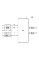
- FIG. 1 is a schematic configuration diagram of a vehicle control system according to an embodiment of the present invention.
- the flowchart of the calculation process of a preceding vehicle lap ratio The flowchart of the calculation process of the own lane lap rate.
- the flowchart of the calculation process of the output time of a rear-end collision warning The flowchart of the output process of an alarm.
- the vehicle control system is mounted on a vehicle (hereinafter, this device-equipped vehicle is referred to as a host vehicle), detects an object existing in front of the host vehicle, and avoids / reduces a collision with the object. It functions as a PCS system that performs various controls.
- a vehicle control system 100 mounted on a host vehicle includes an ECU (electrical control unit) 10 that is a vehicle control device, a radar 21, an imaging device 22, various sensors, an alarm device 40, and a braking device 50. Has been.
- ECU electronic control unit
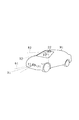
- the radar 21 detects an object in front of the host vehicle as a radar target LT using a directional electromagnetic wave such as a millimeter wave or a laser, and as shown in FIG. 2, at the front portion of the host vehicle M1.
- the optical axis X1 is attached so as to face the front of the vehicle. Then, every predetermined time, the radar 61 scans an area 61 that extends over the range of the predetermined angle ⁇ 1 toward the front of the vehicle with the optical axis X1 as the center, and receives electromagnetic waves reflected on the surface of an object outside the vehicle, Input to the ECU 10.
- the radar 21 has detected an object when the reflected wave of the radar can be received with a predetermined or higher reception intensity. Therefore, whenever the radar 21 receives a reflected wave with a reception intensity equal to or higher than a predetermined threshold, the radar 21 receives one radar target LT and inputs the radar target LT to the ECU 10.
- the radar target LT includes information such as the distance to the object in the traveling direction of the host vehicle, the relative speed, and the lateral position indicating the position of the host vehicle in the vehicle width direction.
- the imaging device 22 is a CCD camera, a monocular camera, a stereo camera, or the like, and is installed near the upper end of the windshield of the host vehicle M1 as shown in FIG. Then, at every predetermined time, an image 62 is acquired by capturing an area 62 that extends in the range of the predetermined angle ⁇ 2 toward the front of the vehicle with the imaging axis X2 as the center. Then, the captured image is subjected to image processing to obtain an object as an image target GT and input to the ECU 10.
- the image target GT includes information such as the lateral width of the object in addition to the distance and relative speed with the object in the traveling direction of the host vehicle, the lateral position indicating the position of the host vehicle in the vehicle width direction. Therefore, the ECU 10 recognizes the image target GT as information having a predetermined width.
- a yaw rate sensor 23 is a known sensor that detects the turning angular velocity (yaw rate ⁇ ) of the vehicle
- the vehicle speed sensor 24 detects the speed of the host vehicle (own vehicle speed V) based on the rotational speed of the wheels.
- the steering angle sensor 25 detects an angle at which the steering wheel of the host vehicle is rotated as a steering angle.
- the alarm device 40 is a speaker, a display, or the like, and is used to output an alarm in a state where the driver can recognize it using vision or hearing, such as voice or image.
- the braking device 50 is a seat belt, a brake, or the like, and is used to reduce a driver's collision damage by winding up the seat belt or to reduce a collision speed by a brake operation.
- the ECU 10 is an electronic control unit that controls the vehicle control system.
- the ECU 10 is mainly composed of a central processing unit (CPU), and includes a read-only memory (ROM), a random access memory (RAM), an input / output interface, and the like. It is configured.
- Various functions to be described from the ECU 10 are realized by the CPU executing a program stored in the ROM.
- the ECU 10 detects objects (vehicles, obstacles, pedestrians, etc.) other than the subject vehicle based on the information on each target acquired by the radar 21 and the imaging device 22. Then, it is determined whether or not there is a possibility of collision with these objects, and when it is determined that there is a high possibility of collision, the alarm device 40 and the braking device 50 are operated.
- the ECU 10 switches the operation mode of the alarm device 40 according to the urgency of the collision between the host vehicle and the object (preceding vehicle, oncoming vehicle, etc.). For example, when the urgency level of the collision is low, a guide voice describing the presence of the object is output. When the urgency level of the collision is medium, a warning sound is output so as to be directed to the driver from the direction corresponding to the position of the object. When the urgency level of the collision is high, a rear-end collision warning PRE (PERCEPTUAL RISK ESTIMATE) for prompting collision avoidance for the object is output.
- PRE PERCEPTUAL RISK ESTIMATE
- the warning device 40 is activated as soon as possible for the rear-end collision warning PRE.
- the timing of the rear-end collision warning PRE is too early, the avoidance operation by the driver and the output timing of the warning interfere with each other, giving the driver unpleasant feeling.
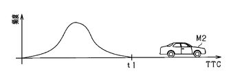
- the ECU 10 obtains a distribution of the frequency of the avoidance operation by the driver by accumulating a history of the timing of the avoidance operation of the driver when the driver of the host vehicle has reached a predetermined distance from the preceding vehicle. For example, in a scene where the host vehicle M1 and the preceding vehicle M2 approach a predetermined distance, the frequency distribution of the driver's avoidance operation as shown in FIG. 3 is monitored by monitoring the timing at which the driver steps on the brake as the avoidance operation. Is obtained.
- the horizontal axis represents a collision margin time TTC (Time to Collision) corresponding to the time until the vehicle collides with an object such as the preceding vehicle M2 ahead of the host vehicle.
- TTC is an evaluation value indicating how many seconds later the collision occurs when the vehicle travels at the vehicle speed Vs as it is.
- the smaller the TTC the higher the risk of collision (the right side in FIG. 3), and the larger the TTC.
- the risk of collision is low (left side of FIG. 3).
- the driver There is a possibility that the avoidance operation and the rear-end collision warning PRE interfere with each other. Therefore, the timing after TTC (for example, time t1) at which the driver's avoidance operation may be performed is set as the output timing of the rear-end collision warning PRE. As described above, interference between the driver's avoidance operation and the rear-end collision warning PRE can be avoided.
- the risk of collision between the host vehicle and the preceding vehicle changes depending on the positional relationship between the host vehicle and the preceding vehicle, the approaching state of the preceding vehicle with respect to the host vehicle, and the like.
- the risk of collision is low, it may be possible to delay the avoidance operation after the driver notices an object in front of the host vehicle. Therefore, in the situation where the risk of collision is low, even if the rear-end collision PRE is output at a timing set based on the driver's avoidance model, the driver's avoidance operation and the output timing of the rear-end collision PRE may interfere. There is sex.
- the ECU 10 changes the output timing of the rear-end collision alarm PRE in consideration of the risk of a collision of the host vehicle, thereby suppressing the output of the rear-end collision alarm PRE more unnecessary.
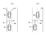
- the vehicle width (own vehicle width) of the host vehicle M1 and the vehicle width of the preceding vehicle M2 overlap.
- the risk of collision changes according to the ratio (lap rate). That is, in FIG. 4, as the lap rate between the host vehicle M1 and the preceding vehicle M2 (hereinafter referred to as the preceding vehicle lap rate) decreases (as the left side of the page), the risk of collision decreases, and the driver moves to the preceding vehicle M2. It is assumed that the avoidance operation will be carried out later after noticing.
- the ECU 10 indicates the risk of collision when the preceding vehicle M2 is in front of the host vehicle M1 in the own lane, and the lateral position of the host vehicle M1 and the lateral position of the preceding vehicle M2 overlap.
- the preceding vehicle lap rate is obtained as a parameter.
- the output timing of the rear-end collision alert PRE set based on the driving history of the driver is changed based on the preceding vehicle lap rate. That is, the timing at which the rear-end collision warning PRE is output is changed to the delay side as the preceding vehicle lap rate becomes smaller and the possibility that the driver avoids the steering avoidance timing becomes higher.
- the ECU 10 determines, as the moving state determination unit (33), when the preceding vehicle M2 (or the oncoming vehicle M3) exceeds the white line WL (or the white line WR) and overlaps the own lane TL, Alternatively, it is determined whether the oncoming vehicle M3) is approaching or separating from the host vehicle M1.
- the approaching state and the separating state are obtained from the lateral speed of the preceding vehicle M2 (or the oncoming vehicle M3).
- the lateral speed is a moving speed in a direction orthogonal to the own lane TL.
- a lap rate between the preceding vehicle M2 and the own lane (hereinafter, the own lane lap rate) is obtained as a parameter indicating the risk of collision.
- the output timing of the rear-end collision warning PRE set based on the driving history of the driver is changed using the own lane lap rate. That is, the timing at which the rear-end collision warning PRE is output is changed to the delay side as the lane wrap rate decreases and the possibility that the driver avoids the steering avoidance becomes higher.
- the ECU 10 includes a radar target acquisition unit 11, an image target acquisition unit 12, a fusion processing unit 13, a lateral position correction unit 14, a vehicle determination unit 31, a predicted course estimation unit 32, and a movement state determination unit. 33, a preceding vehicle lap rate calculation unit 15, an own lane lap rate calculation unit 16, an estimated model generation unit 17, a rear-end collision alarm setting unit 18, and a vehicle control unit 19 are provided.
- the radar target acquisition unit 11 acquires information on the radar target LT detected by the radar 21 at predetermined intervals.
- the image target acquisition unit 12 acquires information on the image target GT detected by the imaging device 22 every predetermined period.
- the fusion processing unit 13 fuses the radar target LT and the image target GT (fusion) to generate a fusion target FSN. Specifically, the position of the fusion target in the traveling direction of the host vehicle is specified based on the distance and relative speed of the radar target LT, and the width of the fusion target in the vehicle width direction of the host vehicle is determined based on the lateral width and lateral position of the image target GT. Identify the location.
- the fusion target FSN is generated using the radar target LT and the image target GT, and the position of the object is specified by the fusion target FSN, among the information acquired by the radar 21 and the imaging device 22
- the position of the object is specified using information with higher accuracy, and the recognition accuracy of the position of the object can be improved.
- the lateral position of the end of the object in the vehicle width direction can be specified by the lateral position of the fusion target FSN.
- the side approaching the host vehicle may be selected as the lateral position of the object to be controlled.
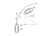
- an estimated R that is the curve radius (the reciprocal of the curvature) of the predicted path of the host vehicle is obtained by the predicted path estimation unit 32 that estimates the curvature of the predicted path of the host vehicle. Then, the lateral position correction unit 14 corrects the lateral position of the object using the estimated R.
- the correction by the correction value ⁇ x is not performed when the host vehicle is stopped when the estimated R is zero or when the host vehicle is traveling straight ahead when the estimated R is greater than a predetermined threshold.
- the radar target 21 and the imaging device 22 are not fused, that is, when the object is detected by only one of the radar 21 and the imaging device 22, the radar target 21 or the imaging device 22 is used.
- the position of the object may be specified based on the target information. Specifically, when only the radar target LT is detected, the position (distance, lateral position, etc.) of the object is specified using the radar target LT.
- the position (distance, lateral position, etc.) of the object is specified using the image target GT.
- the preceding vehicle lap rate calculation unit 15 calculates the preceding vehicle lap rate as a parameter indicating the risk of collision.
- the preceding vehicle lap rate can be calculated using the avoidance margin between the preceding vehicle and the host vehicle.
- the avoidance margin width can be calculated from the vehicle width of the host vehicle and the overlapping amount in the vehicle width direction between the host vehicle and the preceding vehicle.
- the amount of overlap in the vehicle width direction between the host vehicle and the preceding vehicle can be obtained, for example, by comparing the lateral position of the preceding vehicle with the lateral position of the host vehicle.
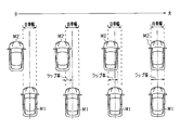
- the lap state between the preceding vehicle and the own vehicle can be classified into three patterns shown in FIG. 7 according to the positional relationship between the own vehicle and the preceding vehicle and the size relationship of the vehicle width. That is, as shown in FIG. 7A, the preceding vehicle M2 is offset with respect to the host vehicle M1. As shown in FIG. 7B, when the vehicle width of the preceding vehicle M2 is larger than the vehicle width of the host vehicle M1, the entire host vehicle M1 overlaps the preceding vehicle M2. As shown in FIG. 7C, when the vehicle width of the preceding vehicle M2 is narrower than the vehicle width of the own vehicle M1, the preceding vehicle M2 is included in the vehicle width of the own vehicle M1, Is one pattern. For example, the preceding vehicle lap rate of each pattern is calculated as follows.
- the avoidance margin width Xa is calculated from the difference between the lateral position of the host vehicle M1 and the lateral position of the preceding vehicle, and the avoidance margin width Xa is subtracted from the vehicle width X0 of the host vehicle. Find the preceding car lap rate.
- the avoidance margin width Xa 0 of the own vehicle, the preceding vehicle lap ratio is 100%.
- the larger avoidance margin width Xa (here, the avoidance margin width Xa on the right side of the host vehicle) is subtracted from the vehicle width X0 of the host vehicle to calculate the preceding vehicle lap ratio.
- the own lane lap rate calculation unit 16 calculates the own lane lap rate as a parameter indicating the risk of collision.
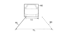
- calculation of the own lane wrap rate will be described with reference to FIG. FIG. 8 is a captured image acquired by the imaging device 22, and the white line WL on the left side and the white line WR on the right side of the own lane TL are detected by image processing of the captured image.
- the preceding vehicle M2 is detected as an FSN target. In this case, since the preceding vehicle M2 overlaps the white line WL on the left side, the width LL inside the own lane with respect to the white line WL on the left side is calculated as the own lane wrap rate.
- the own lane lap rate is calculated on the condition that the preceding vehicle is moving laterally away from the own vehicle, and the output timing of the rear-end collision warning PRE is changed using the own lane lap rate.
- the preceding vehicle lap rate calculation unit 15 and the own lane lap rate calculation unit 16 constitute a determination unit 34 (see FIG. 1B) that determines the risk of collision of the host vehicle based on the position of the object ahead of the host vehicle.
- the own lane lap rate calculation unit 16 and the preceding vehicle lap rate calculation unit 15 each have their own lane lap that is a lap rate between the object and the own lane when the object overlaps the own lane on which the own vehicle travels. It corresponds to the 1st determination part 16 which determines the danger of a collision based on a rate, and the 2nd determination part 15 which determines the risk of a collision based on the preceding vehicle lap rate which is a lap rate of the own vehicle and a preceding vehicle. .
- the estimation model generation unit 17 generates an estimation model for estimating the timing of the avoidance operation by the driver by formulating the distribution of the frequency of the avoidance operation by the driver. For example, an estimation model is generated using Equation (1).
- Vs is the own vehicle speed acquired from the vehicle speed sensor 24.
- D is a relative distance
- Vr is a relative velocity
- Ap is a relative acceleration, which can be obtained from information on the fusion target FSN.
- ⁇ , ⁇ , and n are coefficients determined by matching. Then, the output timing TPRE of the rear-end collision alarm PRE is set so that the avoidance operation timing estimated based on the equation (1) and the rear-end collision alarm PRE do not interfere with each other.
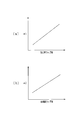
- the estimation model generation unit 17 of the present embodiment obtains a coefficient used for the above calculation from the preceding vehicle lap rate. Then, the estimated model is changed by substituting the obtained coefficient into the equation (1).
- the estimated model is changed using the coefficient ⁇ 1 calculated based on the preceding vehicle lap ratio instead of the coefficient ⁇ in the equation (1).
- the coefficient ⁇ 1 is calculated using the correlation between the preceding vehicle lap ratio and the coefficient ⁇ 1 shown in FIG.
- the coefficient ⁇ 1 is set to a smaller value as the preceding vehicle lap ratio becomes smaller. Therefore, the timing of the driver's avoidance operation estimated by the estimation model is shifted to the delay side as the preceding vehicle lap ratio is small and the risk of collision is low, and the output timing TPER of the rear-end collision warning PRE is set to the delay side. Can be changed. As described above, it is possible to suppress an unnecessary warning from being output while suppressing interference between the driver's avoidance operation and the rear-end collision warning PRE.
- the estimated model generation unit 17 obtains a coefficient used for the above calculation from the own lane lap rate. Specifically, the estimated model is changed using the coefficient ⁇ 2 calculated based on the own lane lap rate instead of the coefficient ⁇ in the equation (1).
- the coefficient ⁇ 2 is calculated using the correlation between the own lane wrap rate and the coefficient ⁇ 2 shown in FIG. Also in FIG. 9B, the coefficient ⁇ 2 is set to a smaller value as the own lane wrap ratio decreases. Therefore, the lower the own lane lap rate and the lower the risk of collision, the more the driver avoidance operation timing estimated by the estimation model is shifted to the delay side, and the output timing TPER of the rear-end collision warning PRE is set to the delay side. Can be changed. As described above, it is possible to suppress an unnecessary warning from being output while suppressing interference between the driver's avoidance operation and the rear-end collision warning PRE.
- the estimated model generation unit 17 includes a distribution calculation unit 35, an alarm output setting unit 36, and a change unit 37 as functional blocks.
- the distribution calculation unit 35 accumulates a history of timings of avoidance operations performed by the driver of the host vehicle on an object existing at a predetermined distance ahead of the host vehicle, and calculates a distribution of timings of the avoidance operation.
- an estimation model that estimates the timing of the avoidance operation by the driver by formulating the distribution of the frequency of the avoidance operation by the driver is used.
- the alarm output setting unit 36 sets the output timing of an alarm for the driver based on the distribution of the timing of the avoidance operation so that the avoidance operation and the actual operation of the driver do not interfere with each other.
- an alarm output timing for the driver in this embodiment, the output of the rear-end collision alarm PRE
- Timing TPRE is set.
- the changing unit 37 changes the alarm output timing set by the alarm output setting unit 36 based on the risk of collision of the host vehicle determined by the determining unit 34.
- the risk of collision when the object overlaps the own lane in which the host vehicle travels in the own lane lap rate calculation unit 16 of the determination unit 34, In the preceding vehicle lap rate calculation unit 15 of the determination unit 34 determined based on the own vehicle lap rate that is the lap rate with the lane, and based on the preceding vehicle lap rate that is the lap rate between the host vehicle and the preceding vehicle Some have been judged.
- the change unit 37 changes the alarm output timing based on the own lane lap rate from the determination unit 34 and the second change unit 38 changes the alarm output timing based on the preceding vehicle lap rate from the determination unit 34. And a change unit 39.
- the rear-end collision alarm setting unit 18 outputs the rear-end collision alarm PRE output timing calculated by the second changing unit 39 based on the preceding vehicle lap rate for the same object (preceding vehicle, oncoming vehicle), and the first changing unit 38 in the own lane.
- the output timing of the rear-end collision alarm PRE calculated based on the lap rate, it functions as a selection unit that selects the earlier one of the alarm output timings as the output timing.
- priority is given to the output timing with the higher degree of danger. As described above, unnecessary warning output is suppressed while appropriately warning the driver.
- the vehicle control unit 19 calculates a collision margin time TTC (Time to collision) based on the relative position and relative speed between the host vehicle and the preceding vehicle. Then, when the TTC is the output timing of the rear-end collision alarm PRE set by the rear-end collision alarm setting unit 18, an operation command is output to the alarm device 40. As a result, an alarm is output from the alarm device 40.
- the TTC may be calculated by taking into account the relative acceleration between the host vehicle and the preceding vehicle.
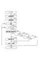
- FIG. 10 is a flowchart of the preceding vehicle lap rate calculation process.
- FIG. 11 is a flowchart of the calculation process of the own lane lap rate.
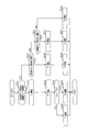
- FIG. 12 is a flowchart of the calculation process of the output timing of the rear-end collision warning PRE.
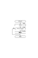
- FIG. 13 is a flowchart of an alarm output process in the PCS control of this embodiment. Each of these processes is repeatedly performed by the ECU 10 at a predetermined cycle.
- ECU10 acquires the information of the own vehicle in step S11. For example, vehicle speed, steering angle, acceleration information, deceleration information, and the like are acquired as information on the host vehicle.
- step S12 the ECU 10 acquires information on an object such as a preceding vehicle.
- information such as the relative distance, relative speed, relative lateral position, and vehicle width of an object is acquired from an FSN target or the like.
- ECU10 determines whether an object is a vehicle in step S13.
- the vehicle determination unit 31 performs well-known image processing such as template matching on the photographed image of the imaging device 22, so that the type of a predetermined object existing in the imaging range (another vehicle, a pedestrian) , Road obstacles, etc.) are detected, and determination is made based on the detection result.
- step S14 determines whether other vehicles (namely, preceding vehicle) overlap with the own vehicle in step S14, when step S13 is affirmed. This process can be determined from the positional relationship between the lateral position of the host vehicle and the lateral position of the other vehicle. If it is determined in step S14 that the other vehicle overlaps with the host vehicle, the ECU 10 calculates a preceding vehicle lap ratio in steps S15 to S19.
- step S15 the ECU 10 determines whether or not the vehicle width of the preceding vehicle is smaller than the vehicle width of the host vehicle. Whether the vehicle width of the preceding vehicle is smaller than the vehicle width of the host vehicle is determined based on the detection result of the lateral position and the lateral width of the object acquired from the fusion target FSN or the like. If the determination in step S15 is affirmative, the ECU 10 calculates an avoidance margin width in the left-right direction of the preceding vehicle relative to the host vehicle in step S16. The avoidance margin width can be obtained by comparing the left and right lateral positions of the host vehicle with the left and right lateral positions of the preceding vehicle and calculating the difference.
- step S17 the ECU 10 calculates the preceding vehicle lap ratio using the larger one of the left and right avoidance margin widths.
- step S15 determines in step S18 whether the preceding vehicle is offset with respect to the host vehicle. Whether or not there is an offset can also be determined based on the detection result of the lateral position of the object acquired from the fusion target FSN or the like.
- the ECU 10 also proceeds to step S16 when it determines that there is an offset in step S18, and calculates an avoidance margin. In this case, the avoidance margin on the side where the preceding vehicle is offset from the own vehicle is calculated.
- step S17 the ECU 10 calculates the preceding vehicle lap rate using the avoidance margin.
- step S18 the ECU 10 proceeds to step S19 and determines whether or not the host vehicle is a full lap (the lap rate is 100%) with respect to the preceding vehicle. If the ECU 10 determines in step S19 that the host vehicle is a full lap with respect to the preceding vehicle, the ECU 10 proceeds to step S17 and sets the preceding vehicle lap rate to 100%. If negative in S13 and S14, the process is terminated.
- step S31 the ECU 10 acquires information on the own vehicle. For example, vehicle speed, steering angle, acceleration information, deceleration information, and the like are acquired as information on the host vehicle.
- ECU10 acquires the information of objects, such as a preceding vehicle, in step S32.
- information such as the relative distance, relative speed, relative lateral position, and vehicle width of the object is acquired using an FSN target or the like.
- step S33 the ECU 10 determines whether or not the object is a vehicle.
- the vehicle determination unit 31 performs well-known image processing such as template matching on the photographed image of the imaging device 22, so that the type of a predetermined object existing in the imaging range (another vehicle, a pedestrian) , Road obstacles, etc.) are detected, and determination is made based on the detection result.
- ECU10 determines whether the vehicle (other vehicle) has overlapped with the white line of the own lane in step S34, when step S33 is affirmed. This process can be determined by comparing the lateral position of the other vehicle with the position of the white line.
- step S34 determines in step S35 whether the other vehicle is in a stopped state. This process is affirmed when the lateral movement speed of the vehicle is zero. The flow of processing proceeds to step S36 when the other vehicle is in a stopped state.
- step S35 If it is determined in step S35 that the other vehicle is not stopped, the ECU 10 determines in step S37 whether or not the other vehicle is separated from the own vehicle. If no in step S37, the process is terminated. If the determination in step S37 is affirmative, the ECU 10 acquires, in step S36, the width on the own lane side with respect to the white line as the own lane wrap rate in the other vehicle. If the determination in S33 or S34 is negative, the process is terminated.
- step S44 If step S44 is affirmed, the ECU 10 sets the output timing Tb to the output timing of the rear-end collision warning PRE in step S45. If step S44 is negative, the ECU 10 sets the output timing Ta to the output timing of the rear-end collision warning PRE in step S46.
- step S41 determines in step S41 whether or not only the preceding vehicle lap rate has been acquired. If the determination in step S47 is affirmative, the ECU 10 calculates the output timing Ta of the rear-end collision warning PRE using the estimated model obtained using the coefficient ⁇ 1 calculated from the preceding vehicle lap ratio in step S48. In step S49, the ECU 10 sets the output timing Ta to the output timing of the rear-end collision warning PRE.
- step S50 determines in step S50 whether or not only the own lane lap rate has been acquired. If the determination in step S50 is affirmative, the ECU 10 calculates the output timing Tb of the rear-end collision warning PRE in step S51 using the estimation model obtained using the coefficient ⁇ 2 calculated from the own lane lap rate. In step S52, the ECU 10 sets the output timing Tb to the output timing of the rear-end collision alarm PRE.
- the ECU 10 calculates a collision margin time TTC (Time to collision) of the own vehicle with respect to an object (such as a preceding vehicle).
- TTC may be calculated based on the relative distance and relative speed between the host vehicle and the preceding vehicle, or may be calculated in consideration of the relative acceleration.
- step S62 the ECU 10 determines whether or not the TTC calculated in step S61 is the output timing TPRE of the rear-end collision alarm PRE. If no in step S62, the process is terminated. If the determination in step S62 is affirmative, the ECU 10 outputs a rear-end collision warning PRE in step S63.
- a history of timings of avoidance operations performed by the driver of the host vehicle on an object (such as a preceding vehicle) existing at a predetermined distance ahead of the host vehicle is accumulated, and a distribution of timings of the avoidance operation is calculated. Based on the calculated avoidance operation timing distribution, an alarm output timing for the driver is set so that the avoidance operation and the driver's actual avoidance operation do not interfere with each other. Thereby, it is possible to suppress the output of unnecessary alarms by taking into consideration statistical data regarding the driver.
- the driver's avoidance operation and the alarm may interfere with each other, leading to driver discomfort.
- the risk of collision with the host vehicle is determined based on the position of the object in front of the host vehicle. And based on the determination result, the alarm output timing set based on the distribution of the timing of the avoidance operation is changed. In this case, unnecessary alarm output to the driver can be suppressed while suppressing interference with the driver's avoidance operation.
- the collision avoidance control is performed on the assumption that the preceding vehicle or the like is detected as the FSN target.
- the radar target LT detected by the radar 21 or the image target GT detected by the imaging device 22 may be performed using any information.
- the output timing of the rear-end collision warning PRE is changed on condition that the preceding vehicle and the white line overlap and the preceding vehicle moves in a direction away from the own vehicle.
- the output timing of the rear-end collision warning PRE may be changed only on the condition that the preceding vehicle overlaps the own lane.
- a plurality of object detection devices of the radar 21 and the imaging device 22 are used to identify an object in front of the host vehicle.
- at least one of the radar 21 and the imaging device 22 is What is necessary is just to be provided.
- model of the driver's avoidance operation is obtained by monitoring the timing of stepping on the brake as the driver's avoidance operation.
- a model of the driver's avoidance operation may be obtained by monitoring the timing at which the steering operation is performed as the driver's avoidance operation.
- the distribution of the frequency of avoidance operations by the driver is formulated.
- the distribution of the frequency of avoidance operations by the driver may be represented by a map or the like.
- the output timing TPRE of the rear-end collision alarm PRE is set using the map so that the timing of the driver's avoidance operation and the rear-end collision alarm PRE do not interfere with each other.
Landscapes
- Engineering & Computer Science (AREA)
- Remote Sensing (AREA)
- Radar, Positioning & Navigation (AREA)
- Physics & Mathematics (AREA)
- General Physics & Mathematics (AREA)
- Automation & Control Theory (AREA)
- Transportation (AREA)
- Mechanical Engineering (AREA)
- Computer Networks & Wireless Communication (AREA)
- Multimedia (AREA)
- Theoretical Computer Science (AREA)
- Human Computer Interaction (AREA)
- Electromagnetism (AREA)
- Traffic Control Systems (AREA)
Priority Applications (1)
| Application Number | Priority Date | Filing Date | Title |
|---|---|---|---|
| US15/578,662 US10625739B2 (en) | 2015-06-02 | 2016-05-31 | Vehicle control apparatus and vehicle control method |
Applications Claiming Priority (2)
| Application Number | Priority Date | Filing Date | Title |
|---|---|---|---|
| JP2015-112613 | 2015-06-02 | ||
| JP2015112613A JP6363558B2 (ja) | 2015-06-02 | 2015-06-02 | 車両制御装置、及び車両制御方法 |
Publications (1)
| Publication Number | Publication Date |
|---|---|
| WO2016194900A1 true WO2016194900A1 (ja) | 2016-12-08 |
Family
ID=57441296
Family Applications (1)
| Application Number | Title | Priority Date | Filing Date |
|---|---|---|---|
| PCT/JP2016/066020 Ceased WO2016194900A1 (ja) | 2015-06-02 | 2016-05-31 | 車両制御装置、及び車両制御方法 |
Country Status (3)
| Country | Link |
|---|---|
| US (1) | US10625739B2 (enExample) |
| JP (1) | JP6363558B2 (enExample) |
| WO (1) | WO2016194900A1 (enExample) |
Cited By (3)
| Publication number | Priority date | Publication date | Assignee | Title |
|---|---|---|---|---|
| JP2019043195A (ja) * | 2017-08-30 | 2019-03-22 | マツダ株式会社 | 車両制御装置 |
| CN116572945A (zh) * | 2022-02-10 | 2023-08-11 | 丰田自动车株式会社 | 驾驶辅助装置、方法、非暂时性存储介质和车辆 |
| US12592067B2 (en) * | 2023-10-07 | 2026-03-31 | Hon Hai Precision Industry Co., Ltd. | Early warning method for anti-collision, vehicle mounted device and storage medium |
Families Citing this family (18)
| Publication number | Priority date | Publication date | Assignee | Title |
|---|---|---|---|---|
| US9919648B1 (en) | 2016-09-27 | 2018-03-20 | Robert D. Pedersen | Motor vehicle artificial intelligence expert system dangerous driving warning and control system and method |
| JP6983915B2 (ja) * | 2017-06-12 | 2021-12-17 | コンチネンタル オートモーティブ ゲゼルシャフト ミット ベシュレンクテル ハフツング | 後方プリクラッシュセーフティシステム |
| JP7067175B2 (ja) * | 2018-03-23 | 2022-05-16 | 株式会社デンソー | 運転支援装置、運転支援方法、およびコンピュータプログラム |
| KR102077201B1 (ko) * | 2018-07-20 | 2020-02-13 | 현대모비스 주식회사 | 차량의 통합 제어 장치 및 방법 |
| US11059479B2 (en) | 2018-10-08 | 2021-07-13 | Mando Corporation | Collision avoidance apparatus and collision avoidance method |
| KR101964858B1 (ko) | 2018-10-08 | 2019-08-13 | 주식회사 만도 | 충돌 방지 장치 및 충돌 방지 방법 |
| US20220041184A1 (en) * | 2018-10-18 | 2022-02-10 | Caratica Ai Ltd. | Method and system for obstacle detection |
| CN109583434B (zh) * | 2019-01-18 | 2021-04-23 | 浙江吉利汽车研究院有限公司 | 一种车辆重叠度获取方法及装置 |
| JP7283130B2 (ja) * | 2019-02-28 | 2023-05-30 | トヨタ自動車株式会社 | フォースリミッタ制御システム |
| DE102019208507A1 (de) * | 2019-06-12 | 2020-12-17 | Robert Bosch Gmbh | Verfahren zur Bestimmung eines Überlappungsgrades eines Objektes mit einem Fahrstreifen |
| JP7244643B2 (ja) * | 2019-06-21 | 2023-03-22 | 日立Astemo株式会社 | 車両制御装置 |
| JP7172925B2 (ja) * | 2019-09-13 | 2022-11-16 | いすゞ自動車株式会社 | 運転支援装置 |
| US10981507B1 (en) * | 2019-11-07 | 2021-04-20 | Focused Technology Solutions, Inc. | Interactive safety system for vehicles |
| JP7347457B2 (ja) * | 2021-02-25 | 2023-09-20 | いすゞ自動車株式会社 | 運転支援装置及び運転支援方法 |
| JP7830143B2 (ja) * | 2022-01-24 | 2026-03-16 | 株式会社Subaru | 車両の運転支援装置、及び、車両の運転支援システム |
| JP7813145B2 (ja) * | 2022-01-24 | 2026-02-12 | 株式会社Subaru | 車両の運転支援装置 |
| KR20240022034A (ko) | 2022-08-10 | 2024-02-20 | 주식회사 에이치엘클레무브 | 운전자 보조 장치 및 운전자 보조 방법 |
| WO2025069343A1 (ja) * | 2023-09-28 | 2025-04-03 | ヤマハ発動機株式会社 | 鞍乗型車両用fcw装置及び鞍乗型車両用fcw方法 |
Citations (5)
| Publication number | Priority date | Publication date | Assignee | Title |
|---|---|---|---|---|
| JP2007008300A (ja) * | 2005-06-30 | 2007-01-18 | Nissan Motor Co Ltd | 車両用運転操作補助装置および車両用運転操作補助装置を備えた車両 |
| JP2011197915A (ja) * | 2010-03-18 | 2011-10-06 | Toyota Motor Corp | 追突警報装置および追突警報方法 |
| JP2012008696A (ja) * | 2010-06-23 | 2012-01-12 | Toyota Motor Corp | 車両支援装置 |
| JP2013173404A (ja) * | 2012-02-23 | 2013-09-05 | Toyota Motor Corp | 衝突被害軽減システム、装置制御装置、衝突被害低減方法 |
| JP2015207164A (ja) * | 2014-04-21 | 2015-11-19 | 株式会社デンソー | 走行支援装置 |
Family Cites Families (17)
| Publication number | Priority date | Publication date | Assignee | Title |
|---|---|---|---|---|
| JP4578795B2 (ja) * | 2003-03-26 | 2010-11-10 | 富士通テン株式会社 | 車両制御装置、車両制御方法および車両制御プログラム |
| US7206697B2 (en) * | 2003-10-14 | 2007-04-17 | Delphi Technologies, Inc. | Driver adaptive collision warning system |
| US7302339B2 (en) * | 2003-07-21 | 2007-11-27 | Justin Gray | Hazard countermeasure system and method for vehicles |
| US20070078600A1 (en) * | 2005-09-20 | 2007-04-05 | Honeywell International Inc. | System and method of collision avoidance using an invarient set based on vehicle states and dynamic characteristics |
| JP4893118B2 (ja) * | 2006-06-13 | 2012-03-07 | 日産自動車株式会社 | 回避制御装置、この回避制御装置を備える車両および回避制御方法 |
| JP4254844B2 (ja) * | 2006-11-01 | 2009-04-15 | トヨタ自動車株式会社 | 走行制御計画評価装置 |
| RU2011119211A (ru) * | 2008-11-13 | 2012-12-20 | Асер Рич Лимитед. | Система и способ повышения безопасности транспортного средства путем улучшения знания ситуации водителем транспортного средства |
| US20100209890A1 (en) * | 2009-02-18 | 2010-08-19 | Gm Global Technology Operations, Inc. | Vehicle stability enhancement control adaptation to driving skill with integrated driving skill recognition |
| DE112010005654T5 (de) * | 2010-06-08 | 2013-05-29 | Toyota Jidosha Kabushiki Kaisha | Fahrmodell-Erzeugungsvorrichtung und Fahrunterstützungsvorrichtung |
| WO2012172632A1 (ja) * | 2011-06-13 | 2012-12-20 | トヨタ自動車株式会社 | 運転支援装置及び運転支援方法 |
| TWI455073B (zh) * | 2011-12-14 | 2014-10-01 | Ind Tech Res Inst | 車用特定路況警示裝置、系統與方法 |
| US9129519B2 (en) * | 2012-07-30 | 2015-09-08 | Massachussetts Institute Of Technology | System and method for providing driver behavior classification at intersections and validation on large naturalistic data sets |
| BR112015009456B1 (pt) * | 2012-10-26 | 2020-06-02 | Toyota Jidosha Kabushiki Kaisha | Dispositivo de suporte de direcionamento e método de suporte de direcionamento |
| KR101480610B1 (ko) * | 2013-05-21 | 2015-01-08 | 현대자동차주식회사 | 차량의 충돌 방지 장치 및 그 방법 |
| KR101519287B1 (ko) * | 2014-02-14 | 2015-05-11 | 현대자동차주식회사 | 차량 충돌 방지 장치 및 그 방법 |
| US9214086B1 (en) * | 2014-05-30 | 2015-12-15 | Alpine Electronics, Inc. | Vehicle to vehicle wireless communication apparatus with potential crash warning |
| WO2016103460A1 (ja) * | 2014-12-26 | 2016-06-30 | 横浜ゴム株式会社 | 衝突回避システム |
-
2015
- 2015-06-02 JP JP2015112613A patent/JP6363558B2/ja active Active
-
2016
- 2016-05-31 WO PCT/JP2016/066020 patent/WO2016194900A1/ja not_active Ceased
- 2016-05-31 US US15/578,662 patent/US10625739B2/en active Active
Patent Citations (5)
| Publication number | Priority date | Publication date | Assignee | Title |
|---|---|---|---|---|
| JP2007008300A (ja) * | 2005-06-30 | 2007-01-18 | Nissan Motor Co Ltd | 車両用運転操作補助装置および車両用運転操作補助装置を備えた車両 |
| JP2011197915A (ja) * | 2010-03-18 | 2011-10-06 | Toyota Motor Corp | 追突警報装置および追突警報方法 |
| JP2012008696A (ja) * | 2010-06-23 | 2012-01-12 | Toyota Motor Corp | 車両支援装置 |
| JP2013173404A (ja) * | 2012-02-23 | 2013-09-05 | Toyota Motor Corp | 衝突被害軽減システム、装置制御装置、衝突被害低減方法 |
| JP2015207164A (ja) * | 2014-04-21 | 2015-11-19 | 株式会社デンソー | 走行支援装置 |
Cited By (3)
| Publication number | Priority date | Publication date | Assignee | Title |
|---|---|---|---|---|
| JP2019043195A (ja) * | 2017-08-30 | 2019-03-22 | マツダ株式会社 | 車両制御装置 |
| CN116572945A (zh) * | 2022-02-10 | 2023-08-11 | 丰田自动车株式会社 | 驾驶辅助装置、方法、非暂时性存储介质和车辆 |
| US12592067B2 (en) * | 2023-10-07 | 2026-03-31 | Hon Hai Precision Industry Co., Ltd. | Early warning method for anti-collision, vehicle mounted device and storage medium |
Also Published As
| Publication number | Publication date |
|---|---|
| JP6363558B2 (ja) | 2018-07-25 |
| US10625739B2 (en) | 2020-04-21 |
| JP2016224825A (ja) | 2016-12-28 |
| US20180154892A1 (en) | 2018-06-07 |
Similar Documents
| Publication | Publication Date | Title |
|---|---|---|
| JP6363558B2 (ja) | 車両制御装置、及び車両制御方法 | |
| JP6491596B2 (ja) | 車両制御装置及び車両制御方法 | |
| CN108541325B (zh) | 驾驶辅助装置以及驾驶辅助方法 | |
| US8175797B2 (en) | Vehicle drive assist system | |
| JP6561584B2 (ja) | 車両制御装置、及び車両制御方法 | |
| EP2803547B1 (en) | Collision mitigation apparatus | |
| US9470790B2 (en) | Collision determination device and collision determination method | |
| US9819927B2 (en) | Image processing device, image processing method, and device control system | |
| WO2018074287A1 (ja) | 車両制御装置 | |
| JP6787157B2 (ja) | 車両制御装置 | |
| JP2017117344A (ja) | 走行支援装置 | |
| JP2019114030A (ja) | 衝突判定装置 | |
| WO2017065212A1 (ja) | 車両制御装置及び車両制御方法 | |
| WO2017104773A1 (ja) | 移動体制御装置及び移動体制御方法 | |
| JP7054327B2 (ja) | 走行支援装置 | |
| JP6432538B2 (ja) | 衝突予測装置 | |
| WO2017104387A1 (ja) | 物体検知装置及び物体検知方法 | |
| WO2016158634A1 (ja) | 車両制御装置及び車両制御方法 | |
| JP2017068461A (ja) | 車両の運転支援装置 | |
| WO2016186171A1 (ja) | 物体検出装置、及び物体検出方法 | |
| WO2019012995A1 (ja) | 走行支援装置 | |
| JP2017191382A (ja) | 車両制御装置、及び車両制御方法 | |
| JP2018063605A (ja) | 車両制御装置 | |
| WO2017183668A1 (ja) | 車両制御装置、車両制御方法 | |
| JP2012164275A (ja) | 画像認識装置 |
Legal Events
| Date | Code | Title | Description |
|---|---|---|---|
| 121 | Ep: the epo has been informed by wipo that ep was designated in this application |
Ref document number: 16803334 Country of ref document: EP Kind code of ref document: A1 |
|
| WWE | Wipo information: entry into national phase |
Ref document number: 15578662 Country of ref document: US |
|
| NENP | Non-entry into the national phase |
Ref country code: DE |
|
| 122 | Ep: pct application non-entry in european phase |
Ref document number: 16803334 Country of ref document: EP Kind code of ref document: A1 |