WO2016194594A1 - スピンドル - Google Patents
スピンドル Download PDFInfo
- Publication number
- WO2016194594A1 WO2016194594A1 PCT/JP2016/064475 JP2016064475W WO2016194594A1 WO 2016194594 A1 WO2016194594 A1 WO 2016194594A1 JP 2016064475 W JP2016064475 W JP 2016064475W WO 2016194594 A1 WO2016194594 A1 WO 2016194594A1
- Authority
- WO
- WIPO (PCT)
- Prior art keywords
- ring
- rotation
- peripheral surface
- tip
- spindle
- Prior art date
- Legal status (The legal status is an assumption and is not a legal conclusion. Google has not performed a legal analysis and makes no representation as to the accuracy of the status listed.)
- Ceased
Links
Images






Classifications
-
- F—MECHANICAL ENGINEERING; LIGHTING; HEATING; WEAPONS; BLASTING
- F16—ENGINEERING ELEMENTS AND UNITS; GENERAL MEASURES FOR PRODUCING AND MAINTAINING EFFECTIVE FUNCTIONING OF MACHINES OR INSTALLATIONS; THERMAL INSULATION IN GENERAL
- F16C—SHAFTS; FLEXIBLE SHAFTS; ELEMENTS OR CRANKSHAFT MECHANISMS; ROTARY BODIES OTHER THAN GEARING ELEMENTS; BEARINGS
- F16C27/00—Elastic or yielding bearings or bearing supports, for exclusively rotary movement
- F16C27/06—Elastic or yielding bearings or bearing supports, for exclusively rotary movement by means of parts of rubber or like materials
-
- B—PERFORMING OPERATIONS; TRANSPORTING
- B05—SPRAYING OR ATOMISING IN GENERAL; APPLYING FLUENT MATERIALS TO SURFACES, IN GENERAL
- B05B—SPRAYING APPARATUS; ATOMISING APPARATUS; NOZZLES
- B05B5/00—Electrostatic spraying apparatus; Spraying apparatus with means for charging the spray electrically; Apparatus for spraying liquids or other fluent materials by other electric means
- B05B5/025—Discharge apparatus, e.g. electrostatic spray guns
- B05B5/04—Discharge apparatus, e.g. electrostatic spray guns characterised by having rotary outlet or deflecting elements, i.e. spraying being also effected by centrifugal forces
- B05B5/0415—Driving means; Parts thereof, e.g. turbine, shaft, bearings
Definitions
- the present invention relates to a spindle applied to a precision processing machine, an electrostatic coating apparatus, or the like, and more particularly to a spindle that supports a housing portion that rotatably holds a rotating shaft using an O-ring.
- Japanese Unexamined Patent Application Publication No. 2010-261505 discloses a spindle in which a sleeve that rotatably supports a rotating shaft is held in a housing.
- a sleeve is supported with respect to a housing via an O-ring.
- Such an O-ring is usually made of an elastic body such as rubber. The O-ring has a function of absorbing vibrations generated by the high-speed rotation of the spindle rotation shaft and stabilizing the spindle operation.
- a perfluoroelastomer is known as such a material excellent in solvent resistance.
- perfluoroelastomer is excellent in solvent resistance, but generally has higher hardness than rubber materials used for O-rings.
- the perfluoroelastomer O-ring has a smaller deformation amount with respect to external force than a general O-ring. For this reason, the vibration caused by the rotation of the rotating shaft cannot be sufficiently absorbed by the O-ring, and as a result, the rotating shaft of the spindle cannot be stably rotated at a high speed.
- the present invention has been made to solve the above-described problems, and an object of the present invention is to provide a spindle capable of stably rotating a rotating shaft at a high speed.
- a spindle includes a rotating shaft, a housing portion, a cover member, and a plurality of O-rings.
- the housing portion includes a bearing sleeve in which a sleeve through-hole surrounding at least a part of the outer peripheral surface of the rotating shaft is formed.
- the cover member surrounds at least a part of the outer peripheral surface of the housing portion.
- the plurality of O-rings are disposed between the housing part and the cover member, and support the housing part with respect to the cover member.
- the plurality of O-rings include an intermediate O-ring and a rear end side O-ring.
- the O-ring arranged closest to the tip in the direction along the rotation center axis of the rotation shaft is the tip of the rotation shaft from the center of the bearing sleeve in the direction along the rotation center axis of the rotation shaft. It is located in the intermediate region on the rear end side of the rotation axis from the position of the center of gravity of the rotation axis.
- a spindle includes a rotating shaft, a housing portion, a cover member, and a plurality of O-rings.
- the housing portion includes a bearing sleeve in which a sleeve through-hole surrounding at least a part of the outer peripheral surface of the rotating shaft is formed.
- the cover member surrounds at least a part of the outer peripheral surface of the housing portion.
- the plurality of O-rings are disposed between the housing part and the cover member, and support the housing part with respect to the cover member.
- the O-ring arranged closest to the tip in the direction along the rotation center axis of the rotation shaft is an annular groove formed so as to circulate around the rotation center axis on the outer peripheral surface of the housing portion. Placed inside.
- the inner peripheral surface of the annular groove includes a contact portion that comes into contact with the O-ring and a concave portion adjacent to the contact portion.
- a spindle includes a rotating shaft, a housing portion, a cover member, and a plurality of O-rings.
- the housing portion includes a bearing sleeve in which a sleeve through-hole surrounding at least a part of the outer peripheral surface of the rotating shaft is formed.
- the cover member surrounds at least a part of the outer peripheral surface of the housing portion.
- the plurality of O-rings are disposed between the housing part and the cover member, and support the housing part with respect to the cover member.
- the plurality of O-rings include an intermediate O-ring and a tip side O-ring.
- the intermediate O-ring is positioned in the intermediate region on the tip end side of the rotation shaft from the center of the bearing sleeve in the direction along the rotation center axis of the rotation shaft and on the rear end side of the rotation shaft from the position of the center of gravity of the rotation shaft.
- the front end side O-ring is located in a region closer to the front end side of the rotation shaft than the position of the center of gravity of the rotation shaft in the direction along the rotation center axis.
- the front end side O-ring is arranged inside a front end side annular groove formed so as to go around the rotation center axis on the outer peripheral surface of the housing portion.
- the inner peripheral surface of the tip-side annular groove includes a contact portion that contacts the tip-side O-ring and a recess that is adjacent to the contact portion.
- FIG. 2 is a schematic cross-sectional view of a spindle according to Embodiment 1.
- FIG. It is a cross-sectional schematic diagram which shows the state which attached the cup to the rotating shaft front-end
- FIG. 3 is a schematic sectional view taken along line III-III in FIG. It is a schematic diagram for demonstrating the seal structure in the O-ring in the spindle shown in FIG. It is a cross-sectional schematic diagram which shows the modification of the spindle shown in FIG. It is a cross-sectional schematic diagram which shows the modification of the spindle shown in FIG. 6 is a schematic cross-sectional view of a spindle according to Embodiment 2.
- FIG. 8 is a schematic sectional view taken along line VIII-VIII in FIG. It is a cross-sectional schematic diagram which shows the modification of the spindle shown in FIG. 6 is a schematic cross-sectional view of a spindle according to Embodiment 3.
- FIG. It is a cross-sectional schematic diagram which shows the state which attached the cup to the rotating shaft front-end
- FIGS. 1 and 2 are air turbine drive spindle.
- FIG. 1 is a schematic cross-sectional view for explaining a spindle.
- FIG. 2 is a schematic cross-sectional view showing a state where the cup 37 is attached to the tip of the rotating shaft 1 of the spindle.
- the spindle includes a rotating shaft 1, a journal bearing 7 that supports the rotating shaft 1 in the radial direction, a thrust bearing 8 that supports the rotating shaft 1 in the thrust direction, and the rotating shaft 1 via the journal bearing 7 and the thrust bearing 8.
- a housing assembly 2 that is rotatably supported, a cover 5 that is positioned on the outer peripheral side of the housing assembly 2, a rear end side O-ring 23 and an intermediate O-ring 24 that are disposed between the cover 5 and the housing assembly 2, and rotation
- An air supply unit (a drive air supply path 13 and a drive air supply nozzle 14) that is provided so as to be able to eject gas to the shaft 1 is mainly provided.
- a nozzle plate 6 is fixed to the cover 5 so as to cover the rotary shaft 1 in the thrust direction.
- the nozzle plate 6 is provided with the air supply unit.
- the journal bearing 7 and the thrust bearing 8 are configured as, for example, static pressure gas bearings.
- the rotary shaft 1 includes a shaft portion having a cylindrical shape and a thrust plate portion formed so as to extend in the radial direction with respect to the shaft portion.
- the thrust plate portion is connected to one end portion in the axial direction of the shaft portion.
- the one end side of the shaft portion where the thrust plate portion is provided in the axial direction is the rear side
- the other end portion side of the shaft portion located on the opposite side of the thrust plate portion in the axial direction of the shaft portion is It is called the front side.
- a first through hole 17 extending in the thrust direction is formed in the shaft portion and the thrust plate portion.
- a conical cup 37 is attached to the front end of the rotating shaft 1 as shown in FIG.
- a paint supply pipe (not shown) for supplying paint to the cup 37 is disposed inside the first through hole 17.
- the thrust plate portion is formed with a rotary blade 15 and a rotation detection unit (not shown) arranged on the inner peripheral side of the rotary blade 15.
- Rotating shaft 1 has a part of shaft portion housed in housing assembly 2.
- the housing assembly 2 includes a bearing sleeve 4 that faces each part of the outer peripheral surface of the shaft portion of the rotating shaft 1 and the front plane of the thrust plate portion and is formed so as to surround a portion of the shaft portion. Further, the housing assembly 2 includes a housing 3 that is disposed on the outer peripheral side of the bearing sleeve 4 in the radial direction and is fixed to the bearing sleeve 4. In the housing assembly 2, for example, the housing 3 is connected to the cover 5 via a rear end side O-ring 23 and an intermediate O-ring 24.
- the intermediate O-ring 24 rotates from the position of the center of gravity 29 of the rotating shaft 1 on the tip side of the rotating shaft 1 from the center 28 (see FIG. 2) of the bearing sleeve 4 in the direction along the rotating center axis of the rotating shaft 1. It is located in an intermediate region on the rear end side of the shaft 1.
- the rear end side O-ring 23 is located in a rear end side region on the rear end side of the rotary shaft 1 from the center 28 of the bearing sleeve 4 in the direction along the rotation central axis.
- the rear end side O-ring 23 and the intermediate O-ring 24 are respectively arranged in annular grooves formed on the surface of the housing 3 so as to go around the rotation center axis.
- the intermediate O-ring 24 is arranged at a position away from the tip side of the rotary shaft 1 in this way, when the cup 37 or the like is connected to the tip side of the rotary shaft 1 and rotated, When this occurs, the force applied to the intermediate O-ring 24 can be increased as compared with the case where the O-ring is disposed on the distal end side of the rotary shaft 1. For this reason, even when a relatively hard resin or the like is used as the material of the intermediate O-ring 24, vibration due to the rotation of the rotary shaft 1 can be sufficiently absorbed by the deformation of the intermediate O-ring 24. it can.
- a material having high resistance to a solvent is preferably used.
- a perfluoroelastomer that is a fluorine-based rubber can be used as the material. .
- the thrust plate portion of the rotating shaft 1 has a thrust direction that is greater than a region (thick portion) in which the region located on the outer peripheral side in the radial direction is located on the rotation center shaft side (center side).
- the thin portion has a thin thickness.
- the thick portion is formed so as to surround the first through hole 17.
- the thin portion is formed so as to surround the thick portion.
- the rotor blade 15 is formed so as to extend in the thrust direction from the surface located on the rear side on the thin portion of the thrust plate portion.
- the rotary shaft 1 is rotatably provided when the rotary blade 15 receives the gas ejected from the air supply unit.
- the plurality of rotary blades 15 are provided at intervals in the rotational direction of the rotary shaft 1.
- adjacent rotor blades 15 are provided at equal intervals.
- the plurality of rotor blades 15 are arranged along the outer periphery of the thrust plate portion.
- vertical to the thrust direction of the some rotary blade 15 should just be arbitrary shapes.
- it has a front curved surface portion that is located forward in the rotational direction and formed convex in the rotational direction, and a rear curved surface portion that is located rearward in the rotational direction and is convex in the rotational direction. ing.
- the boundary region between the thin portion and the thick portion is provided so that the thickness in the thrust direction changes gently. That is, the surface located on the rear side of the thrust plate portion has a curved surface between the thin portion and the thick portion.
- the portion located on the rear side of the rotor blade 15 and the portion located on the rear side in the thick wall portion are formed on the same surface extending in the radial direction.
- the rotation detection unit can adopt an arbitrary configuration for optically detecting the rotation of the rotation shaft 1.
- surface treatment is performed so that the reflectance is different for each of a plurality of regions divided in the rotation direction. May be.
- the surface located on the rear side in the thick-walled portion when half of the region in the rotation direction of the rotary shaft 1 is irradiated with light such as laser light than the other half, the reflected light is reflected. It is provided to increase the strength.
- the housing assembly 2 including the housing 3 and the bearing sleeve 4 and the cover 5 are provided so that a bearing gap can be formed between the shaft portion of the rotary shaft 1 and the bearing sleeve 4 and between the thrust plate portion and the bearing sleeve 4. It has been.
- the housing assembly 2 and the cover 5 are provided so that gas can be supplied to the bearing gap.
- the housing assembly 2 and the cover 5 each have a bearing gas supply path 10, and each bearing gas supply path 10 is connected to each other.
- One end of the bearing gas supply path 10 is connected to the bearing gas supply port 9 on the outer peripheral surface of the cover 5, and the other end is a bearing gap between the shaft portion of the rotating shaft 1 and the bearing sleeve 4, and the rotating shaft.
- the journal bearing 7 is configured by supplying the gas supplied from the bearing gas supply port 9 to the bearing gas supply path 10 into the bearing gap between the shaft portion of the rotary shaft 1 and the bearing sleeve 4.
- the gas supplied to the bearing gas supply passage 10 from the bearing gas supply port 9 is supplied to the bearing gap between the thrust plate portion of the rotating shaft 1 and the bearing sleeve 4, thereby causing a pressing force and a magnet 16 to be described later. It is constituted by the suction force
- a magnet 16 is disposed in a region facing the thrust plate portion in the thrust direction.
- the magnet 16 is provided so that a magnetic force can be applied to the thrust plate portion.
- the magnet 16 is a permanent magnet, for example. Thereby, the magnet 16 attracts
- the magnet 16 is provided, for example, so as to face the thin portion of the thrust plate portion where the rotor blades 15 are formed in the thrust direction.
- the magnet 16 has, for example, an annular shape when viewed from the thrust direction.
- the cover 5 is fixed to the nozzle plate 6 in the thrust direction.
- the nozzle plate 6 is formed so as to surround portions of the rotating shaft 1 that are not accommodated in the housing assembly 2 and the cover 5 (the outer peripheral end surface of the thrust plate portion in the radial direction and the surface located on the rear side of the thrust plate portion). Yes.
- the nozzle plate 6 is arranged behind the rotating shaft 1. Inside the nozzle plate 6, a flow passage is formed through which the driving gas flows when the driving gas is supplied to and exhausted from the rotary blades 15 formed on the thrust plate portion of the rotating shaft 1. .
- the driving gas is, for example, compressed air.
- the nozzle plate 6 is formed with a driving air supply path 13 and a driving air supply nozzle 14 for supplying a driving gas to the rotary blades 15.
- One end of the drive air supply path 13 is connected to the drive gas supply port 12 on the outer peripheral surface of the nozzle plate 6, and the other end is connected to the drive air supply nozzle 14.
- the drive air supply nozzle 14 is provided so as to be able to eject drive gas from the outer side to the inner side of the rotary shaft 1 in the radial direction with respect to the rotary blade 15.
- a plurality of the drive air supply passages 13 and the drive air supply nozzles 14 may be formed at intervals in the rotational direction. That is, the drive air supply path 13 and the drive air supply nozzle 14 can simultaneously supply the drive gas in the same rotation direction to the rotor blades 15 provided at an arbitrary interval in the rotation direction. It may be provided.
- a partition wall 22 is provided that is located on the rear side of the thrust plate portion of the rotary shaft 1 and faces the thrust plate portion in the thrust direction.
- the partition wall 22 is located on the nozzle plate 6 at the rear side of the thrust plate portion of the rotary shaft 1 at a portion located in the radial direction center side of the driving air supply nozzle 14 and in front of the exhaust hole 11 in the thrust direction. It is provided so as to face the surface.
- the nozzle plate 6 and the partition wall 22 are provided with a driving gas exhaust port 19 provided so as to be able to exhaust the driving gas supplied from the driving air supply nozzle 14 to the rotary blade 15 to the outside of the spindle, and a driving gas exhaust space. 20 and an exhaust hole 11 are formed.
- the driving gas exhaust port 19 is formed in the partition wall 22, and the driving gas exhaust space 20 is formed between the nozzle plate 6 and the partition wall 22.
- the driving gas exhaust port 19 is preferably formed at a position that does not overlap the rotor blade 15 in the thrust direction, and is preferably formed closer to the center than the rotor blade 15 in the radial direction.
- the driving gas exhaust port 19 is preferably formed at a position overlapping the boundary region between the thin portion and the thick portion of the thrust plate portion of the rotating shaft 1 in the thrust direction.
- a portion of the partition wall 22 located on the outer peripheral side in the radial direction with respect to the driving gas exhaust port 19 is formed so as to face the rotary blade 15 in the thrust direction.
- the space 21 sandwiched between the thrust plate portion (thin wall portion) and the partition wall 22 and sandwiched between the adjacent rotary blades 15 includes the driving air supply nozzle 14 and the driving gas exhaust port 19. Each is connected.
- the nozzle plate 6 and the partition wall 22 are further formed with through holes, respectively.
- a through hole is formed in the nozzle plate 6 so as to be located on the radial center side and to be continuous with the first through hole 17 in the thrust direction.
- a through hole is formed in the partition wall 22 so as to be located on the center side in the radial direction and to be connected to the first through hole 17 and the through hole of the nozzle plate 6 in the thrust direction.
- the nozzle plate 6 has a rotation sensor insertion port 18 formed on the outer peripheral side in the radial direction with respect to the through hole and on the central side in the radial direction with respect to the driving gas exhaust port 19.
- a rotation sensor through hole is formed at a position overlapping the rotation sensor insertion port 18 in the thrust direction.
- the rotation sensor insertion port 18 and the rotation sensor through hole are formed so as to face the rotation detection portion in the thrust plate portion in the thrust direction.
- the rotation sensor insertion port 18 and the rotation sensor through-hole are formed in order to arrange a rotation sensor for irradiating the rotation detection portion with light such as laser light and obtaining reflected light.
- the exhaust hole 11 is formed in the nozzle plate 6 on the center side in the radial direction with respect to the driving air supply path 13 and the driving air supply nozzle 14.
- the exhaust hole 11 is formed so as to communicate with the outside of the nozzle plate 6 from the exhaust space 20.
- an exhaust space 20 is formed between the driving gas exhaust port 19 and the exhaust hole 11.
- the exhaust space 20 has a larger volume than the space formed between the thrust plate portion of the rotating shaft 1 and the partition wall 22.
- the driving gas supplied from a driving gas supply source such as an air compressor (not shown) is supplied from the driving gas supply port 12 to the driving supply nozzle 14 through the driving supply passage 13.
- the driving gas supplied to the driving air supply nozzle 14 is ejected toward the rotor blade 15 of the thrust plate portion of the rotating shaft 1 along a direction substantially parallel to the tangential direction (rotation direction) of the thrust plate portion.
- the The rotary blade 15 receives the jetted driving gas at the rear curved surface portion. At this time, the driving gas ejected to the rotary blade 15 reaches the outer peripheral side of the rear curved surface portion and is changed in direction by flowing along the rear curved surface portion, and reaches the exhaust space 20 from the driving gas exhaust port 19.
- the rotation speed of the rotating shaft 1 can be set to, for example, tens of thousands rpm or more. That is, the spindle described above is suitable for an electrostatic coating machine spindle, for example.
- the spindle described above includes the rotary shaft 1, the housing portion (housing assembly 2), the cover member (cover 5 and nozzle plate 6), and a plurality of O-rings (intermediate O-ring 24 and rear end side O-ring 23).
- the housing assembly 2 includes a bearing sleeve 4 in which a sleeve through hole that is a cylindrical through hole surrounding at least a part of the outer peripheral surface of the rotary shaft 1 is formed.
- the cover member (the cover 5 and the nozzle plate 6) surrounds at least a part of the outer peripheral surface of the housing assembly 2.
- the plurality of O-rings are disposed between the housing assembly 2 and the cover 5 and support the housing assembly 2 with respect to the cover 5.
- the plurality of O-rings includes an intermediate O-ring 24 and a rear end side O-ring 23.
- the intermediate O-ring 24 which is an O-ring arranged closest to the tip in the direction along the rotation center axis of the rotation shaft 1 is a bearing in the direction along the rotation center axis of the rotation shaft 1.
- the sleeve 4 is located in the intermediate region on the distal end side of the rotary shaft 1 from the center 28 and on the rear end side of the rotary shaft 1 from the position of the center of gravity 29 of the rotary shaft 1.
- the rear end side O-ring 23 is located in a rear end side region on the rear end side of the rotary shaft 1 from the center 28 of the bearing sleeve 4 in the direction along the rotation central axis.
- one of the plurality of O-rings that support the housing assembly 2 with respect to the cover 5 is conventionally arranged in front of the rotation shaft 1 from the position of the center of gravity 29 of the rotation shaft 1 in the direction along the rotation center axis. It had been.
- a connecting component for example, a coating cup 37 when electrostatic coating is performed
- the front side of the rotating shaft 1 is largely swung.
- the intermediate O-ring 24 is arranged not in a position close to the front side of the rotary shaft 1 as described above, but in an intermediate region that is close to the center 28 of the bearing sleeve 4. If this is the case, the distance from the front side of the rotating shaft 1 swaying around to the intermediate O-ring 24 can be made larger than the conventional O-ring arranged on the front side. As a result, the force applied to the intermediate O-ring 24 due to the swinging around the front side of the rotating shaft 1 can be increased. For this reason, even when a material having higher hardness than the conventional one is used as the material of the intermediate O-ring 24, the deformation amount of the intermediate O-ring 24 can be sufficiently increased. Therefore, the vibration damping effect by the intermediate O-ring 24 can be sufficiently increased. Therefore, it is possible to obtain a spindle capable of stably rotating the rotary shaft 1 at a high speed.
- the above-described center of gravity 29 of the rotary shaft 1 is a connecting part (for example, a conical part called the bell or cup 37 for electrostatic coating shown in FIG. 2) attached to the tip of the rotary shaft 1.
- a connecting part for example, a conical part called the bell or cup 37 for electrostatic coating shown in FIG. 2
- it means the center of gravity when the connecting part is attached to the rotary shaft 1.
- FIG. 3 is a schematic sectional view taken along line III-III in FIG.
- the modification of the spindle basically has the same configuration as the spindle shown in FIGS. 1 and 2 and can obtain the same effect, but the intermediate O-ring 24 is arranged.
- the shape of the inner peripheral surface of the intermediate annular groove is different from that of the spindle shown in FIGS. That is, in the spindle shown in FIG. 3, the intermediate O-ring 24 is arranged inside an intermediate annular groove formed so as to go around the rotation center axis on the outer peripheral surface of the housing 3.
- the inner circumferential surface of the intermediate annular groove includes a contact portion 41 that comes into contact with the intermediate O-ring 24 and a recess 31 that is adjacent to the contact portion 41.
- the surface of the intermediate O-ring 24 has a portion that does not contact the inner circumferential surface (contact portion 41) of the intermediate annular groove and a portion that does not contact (the portion that faces the recess 31). For this reason, when the rotating shaft 1 vibrates, the area of the area pressed from the inner peripheral surface of the intermediate annular groove on the surface of the intermediate O-ring 24 can be made smaller than when the concave portion 31 is not formed. As a result, stress received from the inner peripheral surface of the intermediate annular groove can be concentrated on a part of the surface of the intermediate O-ring 24 (the force applied per unit area on the surface of the intermediate O-ring 24 can be increased).
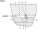
- FIG. 4 is a schematic diagram for explaining that the sealing surface is formed in a state where the intermediate O-ring 24 is disposed inside the above-described intermediate annular groove, along the rotation center axis of the spindle.
- FIG. Therefore, by forming the seal surfaces 32 and 33, the bearing O gas supply path 10 can be sealed by the intermediate O-ring 24.
- the area ratio between the concave portion 31 and the contact portion 41 on the bottom surface of the intermediate annular groove can be appropriately determined in consideration of the mass and the center of gravity of the cup 37 to be mounted.
- the modification of the spindle shown in FIG. 5 basically has the same configuration as that of the spindle shown in FIGS. 1 and 2 and can obtain the same effect.
- the point where the ring 25 is arranged is different from the spindle shown in FIGS. That is, in the spindle shown in FIG. 5, the plurality of O-rings arranged between the housing assembly 2 and the cover 5 have other intermediate O-rings 25 located in the intermediate region in the direction along the rotation center axis. In addition. There may be one or more other intermediate O-rings. In this case, since the vibration of the rotating shaft 1 can also be absorbed by the other intermediate O-ring 25, the rotating shaft 1 can be stably rotated at a high speed.
- one or more other intermediate O-rings 25 are formed on the outer peripheral surface of the housing portion (housing assembly 2) so as to circulate around the rotation center axis. You may each arrange
- the surface of the other intermediate O-ring 25 has a portion that does not come into contact with the inner peripheral surface of the other intermediate annular groove (portion that faces the recess). For this reason, since the stress received from the inner peripheral surface of the other intermediate annular groove can be concentrated on a part of the surface of the other intermediate O-ring 25, the material of the other intermediate O-ring 25 is a material having higher hardness than before. Even when using, the deformation amount of the other intermediate O-ring 25 can be made sufficiently large.
- the plurality of O-rings are positioned in a distal end region on the distal end side of the rotary shaft 1 from the position of the center of gravity 29 (see FIG. 2) of the rotary shaft 1 in the direction along the rotational center axis of the rotary shaft 1.
- a distal O-ring may be included.
- the front end side O-ring may be disposed inside a front end side annular groove formed so as to go around the rotation center axis on the outer peripheral surface of the housing part (housing assembly 2). Similar to the intermediate annular groove shown in FIG. 3, the inner peripheral surface of the distal end side annular groove may include a contact portion that contacts the distal end side O-ring and a concave portion adjacent to the contact portion.
- the vibration of the rotary shaft 1 can be absorbed also by the tip side O-ring, and the position of the rotary shaft 1 in the circumferential direction can be stabilized, so that the rotary shaft 1 is stably rotated at a high speed. be able to.
- stress applied from the inner peripheral surface of the tip-side annular groove can be concentrated on a part of the surface of the tip-side O-ring.
- the amount of deformation of the tip side O-ring can be sufficiently increased.
- the modified example of the spindle shown in FIG. 6 basically has the same configuration as the spindle shown in FIGS. 1 and 2 and can obtain the same effect, but the bearing sleeve 4 rotates the rotary shaft 1. It differs from the spindle shown in FIGS. 1 and 2 in that it is divided in the central axis direction. In FIG. 6, the bearing sleeve 4 is divided into two in the direction of the rotation center axis.
- the center 28 of the bearing sleeve 4 divided into a plurality of parts as described above has a rear end of the bearing sleeve 4 when the distance (full length) from the rear end to the front end of the bearing sleeve 4 in the direction along the rotation center axis is H. It can be defined as a position where the distance from the end is H / 2.
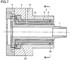
- the spindle according to the present embodiment will be described with reference to FIGS.
- the spindle shown in FIGS. 7 and 8 basically has the same configuration as the spindle shown in FIGS. 1 and 2, except that the spindle shown in FIGS. 7 and 8 is on the outer periphery of the housing assembly 2 in place of the intermediate O-ring 24 described above. 1 and 2 is different from the spindle shown in FIGS. 1 and 2 in that a tip O-ring 26 is arranged in a region located on the tip side of the rotary shaft 1. Further, the front end side O-ring 26 is disposed inside a front end side annular groove formed on the surface of the housing 3. A concave portion 31 is formed on the inner peripheral surface of the tip side annular groove.
- the surface of the tip side O-ring 26 is in contact with the contact portion 41 on the inner peripheral surface of the tip side annular groove, while the recess 31 is formed on the inner peripheral surface of the tip side annular groove. In the region, the surface of the distal O-ring 26 is not in contact with the inner peripheral surface of the distal annular groove.
- the spindle shown in FIGS. 7 and 8 includes a rotating shaft 1, a cover member including a housing portion (housing assembly 2), a cover 5 and a nozzle plate 6, and a plurality of O-rings (rear end O-rings). 23 and a distal O-ring 26).
- the housing assembly 2 includes a bearing sleeve 4 in which a sleeve through hole that is a cylindrical through hole surrounding at least a part of the outer peripheral surface of the rotary shaft 1 is formed.
- the cover 5 included in the cover member surrounds at least a part of the outer peripheral surface of the housing assembly 2.
- the plurality of O-rings are disposed between the housing assembly 2 and the cover 5 and support the housing assembly 2 with respect to the cover 5.
- a distal-side O-ring 26 as an O-ring arranged closest to the distal end in the direction along the rotation center axis of the rotation shaft 1 is around the rotation center axis on the outer peripheral surface of the housing assembly 2. It arrange
- the inner peripheral surface of the tip-side annular groove includes a contact portion 41 that contacts the tip-side O-ring 26 and a recess 31 that is adjacent to the contact portion.
- the surface of the distal O-ring 26 has a portion that does not contact the inner peripheral surface (contact portion 41) of the distal annular groove (portion that faces the recess 31). For this reason, stress received from the inner peripheral surface of the tip-side annular groove can be concentrated on a part of the surface of the tip-side O-ring 26. Therefore, when a material having higher hardness than the conventional is used as the material of the tip-side O-ring 26 Even so, the amount of deformation of the tip side O-ring 26 can be made sufficiently large. Therefore, since the vibration of the rotating shaft 1 can be absorbed by the tip side O-ring 26, the rotating shaft 1 can be stably rotated at a high speed.
- the modification of the spindle shown in FIG. 9 basically has the same configuration as that of the spindle shown in FIGS. 7 and 8 and can obtain the same effect.
- the other tip side O-ring 27 is also arranged inside the other tip side annular groove in the same manner as the tip side O-ring 26.
- the shape of the inner peripheral surface of the other tip-side annular groove in which the other tip-side O-ring 27 is disposed is the same as the shape of the inner periphery of the tip-side annular groove in which the tip-side O-ring 26 is disposed. .
- the other tip side O-ring 27 is formed by another tip side annular groove formed so as to circulate around the rotation center axis on the outer peripheral surface of the housing 3. Arranged inside.
- the inner peripheral surface of another tip-side annular groove includes another contact portion that comes into contact with the other tip-side O-ring 27 and another recess that is adjacent to the other contact portion.
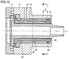
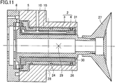
- the spindle according to the present embodiment will be described with reference to FIGS. 10 and 11.
- the spindle shown in FIGS. 10 and 11 basically has the same configuration as the spindle shown in FIGS. 1 and 2, but the rear end side O-ring 23 and the intermediate O-ring shown in FIGS. 24 is different from the spindle shown in FIGS. 1 and 2 in that a distal end side O-ring 26 is arranged in a region located on the distal end side of the rotary shaft 1 on the outer periphery of the housing assembly 2. Yes.
- the front end side O-ring 26 is disposed inside a front end side annular groove formed on the outer peripheral surface of the housing 3.
- the shape of the inner periphery of the tip side annular groove is the same as the shape of the inner periphery of the tip end side annular groove of the spindle shown in FIGS.
- the spindle shown in FIGS. 10 and 11 includes a rotating shaft 1, a cover member including a housing portion (housing assembly 2), a cover 5 and a nozzle plate 6, and a plurality of O-rings (rear end O-rings). 23, an intermediate O-ring 24, and a front end-side O-ring 26).
- the housing assembly 2 includes a bearing sleeve 4 in which a sleeve through hole that is a cylindrical through hole surrounding at least a part of the outer peripheral surface of the rotary shaft 1 is formed.
- the cover 5 surrounds at least a part of the outer peripheral surface of the housing assembly 2.
- the plurality of O-rings are disposed between the housing assembly 2 and the cover 5 and support the housing assembly 2 with respect to the cover 5.
- the plurality of O rings include a rear end side O ring 23, an intermediate O ring 24, and a front end side O ring 26.
- the intermediate O-ring 24 is located at the front end side of the rotary shaft 1 from the center 28 of the bearing sleeve 4 in the direction along the rotary central axis of the rotary shaft 1 and from the position of the center of gravity 29 of the rotary shaft 1.
- the distal-side O-ring 26 is located in a region closer to the distal end of the rotary shaft 1 than the position of the center of gravity 29 of the rotary shaft 1 in the direction along the rotational central axis.
- the front end side O-ring 26 is disposed inside a front end side annular groove formed on the outer peripheral surface of the housing assembly 2 so as to go around the rotation center axis.
- the inner peripheral surface of the tip-side annular groove includes a contact portion 41 (see FIG. 8) that contacts the tip-side O-ring 26 and a recess 31 that is adjacent to the contact portion 41.
- the distance from the front end side (front side) of the rotating shaft 1 to the intermediate O-ring 24 can be made sufficiently large, so that the force applied to the intermediate O-ring 24 due to the swing around the front side of the rotating shaft 1 can be made sufficiently large. .
- the deformation amount of the intermediate O-ring 24 can be sufficiently increased. Therefore, the vibration damping effect by the intermediate O-ring 24 can be sufficiently increased.
- the surface of the distal end side O-ring 26 has a portion that does not contact the inner peripheral surface (contact portion 41) of the distal end side annular groove (a portion that faces the concave portion 31). For this reason, stress received from the inner peripheral surface of the tip-side annular groove can be concentrated on a part of the surface of the tip-side O-ring 26. Therefore, when a material having higher hardness than the conventional is used as the material of the tip-side O-ring 26 Even so, the amount of deformation of the tip side O-ring 26 can be made sufficiently large. Therefore, since the vibration of the rotating shaft 1 can be sufficiently absorbed by the intermediate O-ring 24 and the tip-side O-ring 26, a spindle capable of stably rotating the rotating shaft 1 at a high speed can be obtained.
- the intermediate O-ring 24 is disposed inside an intermediate annular groove formed on the outer peripheral surface of the housing assembly 2 so as to circulate around the rotation center axis.
- the inner circumferential surface of the intermediate annular groove may include another contact portion 41 that contacts the intermediate O-ring 24 and another recess 31 that is adjacent to the other contact portion 41. Good.
- the surface of the intermediate O-ring 24 has a portion that does not contact the inner peripheral surface of the intermediate annular groove and a portion that does not contact (the portion facing the other recess 31). For this reason, the stress received from the inner peripheral surface of the intermediate annular groove can be concentrated on a part of the surface of the intermediate O-ring 24. However, the deformation amount of the intermediate O-ring 24 can be sufficiently increased.
- perfluoroelastomer As a material for the intermediate O-ring 24 and the tip-side O-ring 26, for example, perfluoroelastomer may be used.
- Perfluoroelastomer is a material excellent in solvent resistance, and can be used in a solvent-containing atmosphere as compared with a general nitrile rubber or the like as an O-ring material. Further, the perfluoroelastomer is higher in hardness than the above-mentioned nitrile rubber or the like, but as described above, the perfluoroelastomer is disposed as the intermediate O-ring 24 at a position away from the tip side of the rotating shaft 1 or the recess 31 is formed on the inner periphery.
- high-performance fluororubber having excellent solvent resistance can be used instead of the above-described perfluoroelastomer.
- the present invention is particularly advantageously applied to a spindle used in an electrostatic coating apparatus or the like.
Landscapes
- Engineering & Computer Science (AREA)
- General Engineering & Computer Science (AREA)
- Mechanical Engineering (AREA)
- Support Of The Bearing (AREA)
- Magnetic Bearings And Hydrostatic Bearings (AREA)
Abstract
回転軸を安定して高速回転させることができるスピンドルを提供する。スピンドルは、回転軸(1)と、ハウジングアッシ(2)と、カバー(5)と、複数のOリングを備える。ハウジングアッシ(2)は回転軸(1)の外周面の少なくとも一部を取り囲む軸受スリーブ(4)を含む。カバー(5)は、ハウジングアッシ(2)の外周面の少なくとも一部を取り囲む。複数のOリングは、ハウジングアッシ(2)とカバー(5)との間に配置され、カバー(5)に対してハウジングアッシ(2)を支持する。複数のOリングのうち回転軸(1)の回転中心軸に沿った方向において一番先端寄りに配置された中間Oリング(24)は、回転軸(1)の回転中心軸に沿った方向において、軸受スリーブ(4)の中央(28)より回転軸(1)の先端側であって回転軸(1)の重心(29)の位置より回転軸(1)の後端側の中間領域に位置する。
Description
この発明は、精密加工機や静電塗装装置などに適用されるスピンドルに関し、より特定的には回転軸を回転可能に保持しているハウジング部を、Oリングを用いて支持するスピンドルに関する。
従来、精密加工機や静電塗装装置に用いられるスピンドルが知られている。たとえば、特開2010-261505号公報は、回転軸を回転可能に支持するスリーブがハウジング内に保持されているスピンドルを開示している。特開2010-261505号公報では、ハウジングに対してスリーブがOリングを介して支持されている。このようなOリングは、通常ゴムなどの弾性体によって構成されている。当該Oリングは、スピンドルの回転軸が高速回転することにより発生する振動を吸収し、スピンドルの動作を安定させるといった機能を有する。
ここで、スピンドルが使用される静電塗装装置などは、溶剤雰囲気中で使用されるため、上述したOリングについて耐溶剤性に優れた材料を用いる必要がある。このような耐溶剤性に優れた材料としては、パーフロロエラストマーが知られている。パーフロロエラストマーは上述のように耐溶剤性に優れているが、一般的にOリングに用いられるゴム材料に比べて硬度が高い。その結果、当該パーフロロエラストマー製のOリングは外力に対する変形量が一般的なOリングに比べて小さい。このため、回転軸の回転に起因する振動を当該Oリングにより十分に吸収することができず、結果的にスピンドルの回転軸を安定して高速回転させることができない場合があった。
また、上述のようなパーフロロエラストマーに限らず、スピンドルの使用環境に応じてOリングの材質を適宜選択することが考えられる。このような場合に、当該材質の選択の自由度を高める観点から、一般的なOリングの材料より高硬度の材料を用いた場合でも十分に回転軸の回転による振動を吸収でき、回転軸を安定して高速回転させることができるスピンドルが求められている。
この発明は、上記のような課題を解決するためになされたものであり、この発明の目的は、回転軸を安定して高速回転させることができるスピンドルを提供することである。
本発明の一態様に係るスピンドルは、回転軸と、ハウジング部と、カバー部材と、複数のOリングとを備える。ハウジング部は、回転軸の外周面の少なくとも一部を取り囲むスリーブ貫通穴が形成された軸受スリーブを含む。カバー部材は、ハウジング部の外周面の少なくとも一部を取り囲む。複数のOリングは、ハウジング部とカバー部材との間に配置され、カバー部材に対してハウジング部を支持する。複数のOリングは、中間Oリングと後端側Oリングとを含む。複数のOリングのうち回転軸の回転中心軸に沿った方向において一番先端寄りに配置されたOリングは、回転軸の回転中心軸に沿った方向において、軸受スリーブの中央より回転軸の先端側であって回転軸の重心の位置より回転軸の後端側の中間領域に位置する。
本発明の一態様に係るスピンドルは、回転軸と、ハウジング部と、カバー部材と、複数のOリングとを備える。ハウジング部は、回転軸の外周面の少なくとも一部を取り囲むスリーブ貫通穴が形成された軸受スリーブを含む。カバー部材は、ハウジング部の外周面の少なくとも一部を取り囲む。複数のOリングは、ハウジング部とカバー部材との間に配置され、カバー部材に対してハウジング部を支持する。複数のOリングのうち回転軸の回転中心軸に沿った方向において一番先端寄りに配置されたOリングは、ハウジング部の外周面において回転中心軸の周りを周回するように形成された環状溝の内部に配置される。環状溝の内周面は、Oリングと接触する接触部と、接触部に隣接する凹部とを含む。
本発明の一態様に係るスピンドルは、回転軸と、ハウジング部と、カバー部材と、複数のOリングとを備える。ハウジング部は、回転軸の外周面の少なくとも一部を取り囲むスリーブ貫通穴が形成された軸受スリーブを含む。カバー部材は、ハウジング部の外周面の少なくとも一部を取り囲む。複数のOリングは、ハウジング部とカバー部材との間に配置され、カバー部材に対してハウジング部を支持する。複数のOリングは、中間Oリングと、先端側Oリングとを含む。中間Oリングは、回転軸の回転中心軸に沿った方向において、軸受スリーブの中央より回転軸の先端側であって回転軸の重心の位置より回転軸の後端側の中間領域に位置する。先端側Oリングは、回転中心軸に沿った方向において、回転軸の重心の位置より回転軸の先端側の領域に位置する。先端側Oリングは、ハウジング部の外周面において回転中心軸の周りを周回するように形成された先端側環状溝の内部に配置される。先端側環状溝の内周面は、先端側Oリングと接触する接触部と、接触部に隣接する凹部とを含む。
上記によれば、回転軸を安定して高速回転させることが可能なスピンドルを得ることができる。
以下、図面に基づいて本発明の実施の形態を説明する。なお、以下の図面において同一または相当する部分には同一の参照番号を付しその説明は繰返さない。
(実施の形態1)
<スピンドルの構成>
図1および図2を参照して、本実施の形態に係るスピンドルを説明する。図1および図2に示したスピンドルは、エアタービン駆動スピンドルである。図1は、スピンドルを説明するための断面模式図である。図2は、スピンドルの回転軸1先端にカップ37を取り付けた状態を示す断面模式図である。
<スピンドルの構成>
図1および図2を参照して、本実施の形態に係るスピンドルを説明する。図1および図2に示したスピンドルは、エアタービン駆動スピンドルである。図1は、スピンドルを説明するための断面模式図である。図2は、スピンドルの回転軸1先端にカップ37を取り付けた状態を示す断面模式図である。
スピンドルは、回転軸1と、回転軸1をラジアル方向に支持するジャーナル軸受7と、回転軸1をスラスト方向に支持するスラスト軸受8と、回転軸1をジャーナル軸受7およびスラスト軸受8を介して回転可能に支持するハウジングアッシ2と、ハウジングアッシ2の外周側に位置するカバー5と、カバー5とハウジングアッシ2との間に配置された後端側Oリング23および中間Oリング24と、回転軸1に対し気体を噴出可能に設けられている給気部(駆動用給気路13および駆動用給気ノズル14)とを主に備える。カバー5には、スラスト方向において回転軸1を覆うようにノズル板6が固定して設けられている。当該ノズル板6に、上記給気部が設けられている。ジャーナル軸受7およびスラスト軸受8は、たとえば静圧気体軸受として構成されている。
回転軸1は、円筒形状を有する軸部と、当該軸部に対しラジアル方向に延びるように形成されているスラスト板部とを含む。スラスト板部は、軸部のアキシャル方向における一方の端部に接続されている。以下、アキシャル方向においてスラスト板部が設けられている軸部の上記一方の端部側を後側、軸部のアキシャル方向においてスラスト板部と反対側に位置する軸部の他方の端部側を前側という。軸部およびスラスト板部には、スラスト方向に延びる第1貫通孔17が形成されている。スピンドルが静電塗装機用に構成されている場合には、図2に示すように、回転軸1の前側の端部に円錐形のカップ37が取り付けられる。また、第1貫通孔17の内部にはカップ37に塗料を供給するための図示しない塗料供給管が配置される。スラスト板部には、回転翼15および当該回転翼15の内周側に配置される被回転検出部(図示せず)が形成されている。
回転軸1は、軸部の一部がハウジングアッシ2に収容されている。ハウジングアッシ2は、回転軸1の軸部の外周面およびスラスト板部の前側の平面の各一部に面しており軸部の一部を囲むように形成されている軸受スリーブ4を含む。さらに、ハウジングアッシ2は、ラジアル方向において軸受スリーブ4よりも外周側に配置され、軸受スリーブ4と固定されているハウジング3を含む。ハウジングアッシ2は、たとえばハウジング3が後端側Oリング23および中間Oリング24を介してカバー5と接続されている。中間Oリング24は、回転軸1の回転中心軸に沿った方向において、軸受スリーブ4の中央28(図2参照)より回転軸1の先端側であって回転軸1の重心29の位置より回転軸1の後端側の中間領域に位置する。後端側Oリング23は、回転中心軸に沿った方向において、軸受スリーブ4の中央28より回転軸1の後端側の後端側領域に位置する。後端側Oリング23および中間Oリング24は、それぞれ回転中心軸周りに周回するようにハウジング3の表面に形成された環状溝の内部に配置されている。
このように中間Oリング24が回転軸1の先端側から離れた位置に配置されているので、回転軸1の先端側にカップ37などが接続されて回転したときに当該先端側での振れ回りが発生した場合、回転軸1の先端側にOリングが配置された場合より中間Oリング24に加えられる力を大きくできる。このため、当該中間Oリング24の材料として比較的硬度の高い樹脂などを用いた場合でも、回転軸1の回転に起因する振動を当該中間Oリング24が変形することにより十分に吸収することができる。
中間Oリング24や後端側Oリング23の材料としては、たとえば溶剤に対する耐性が高い材料を用いることが好適であり、たとえば当該材料として、フッ素系のゴムであるパーフロロエラストマーを用いることができる。
また、図1に示されるように、回転軸1のスラスト板部は、ラジアル方向において外周側に位置する領域が回転中心軸側(中央側)に位置する領域(厚肉部)よりもスラスト方向における厚みが薄い薄肉部を有している。厚肉部は上記第1貫通孔17を囲むように形成されている。薄肉部は当該厚肉部を囲むように形成されている。
回転翼15は、スラスト板部の当該薄肉部上において、後側に位置する面からスラスト方向に延びるように形成されている。回転軸1は、回転翼15が給気部から噴出された気体を受けることにより回転可能に設けられている。複数の回転翼15は、回転軸1の回転方向に互いに間隔を隔てて設けられている。好ましくは、複数の回転翼15において隣り合う回転翼15は等間隔に設けられている。複数の回転翼15は、スラスト板部の外周に沿って配置されている。複数の回転翼15のスラスト方向に垂直な断面形状は任意の形状であればよい。たとえば、回転方向において前方に位置して回転方向に凸状に形成されている前方曲面部と、回転方向において後方に位置して回転方向に凸状に形成されている後方曲面部とを有している。
図1に示されるように、スラスト板部において、薄肉部と厚肉部との境界領域は、スラスト方向における厚みがゆるやかに変化するように設けられている。つまり、スラスト板部の後側に位置する面は、薄肉部と厚肉部との間に曲面を有している。回転翼15における後側に位置する部分と厚肉部における後側に位置する部分とは、ラジアル方向に延びる同一面上に形成されている。
厚肉部において後側に位置する面上には、被回転検出部が形成されている。被回転検出部は、回転軸1の回転を光学的に検出するための任意の構成を採用できるが、たとえば回転方向において分割される複数の領域毎に異なる反射率となるように表面処理が施されていてもよい。具体的には、厚肉部において後側に位置する面のうち、回転軸1の回転方向における半分の領域が他の半分の領域よりもレーザ光などの光が照射されたときに反射光の強度が高くなるように設けられている。
ハウジング3および軸受スリーブ4からなるハウジングアッシ2、およびカバー5は、回転軸1の軸部と軸受スリーブ4との間およびスラスト板部と軸受スリーブ4との間にそれぞれ軸受隙間を形成可能に設けられている。また、ハウジングアッシ2およびカバー5は、当該軸受隙間に気体を供給可能に設けられている。具体的には、ハウジングアッシ2およびカバー5は、それぞれ軸受気体供給路10を有しており、それぞれの軸受気体供給路10は互いに接続されている。軸受気体供給路10は、その一方端がカバー5の外周面上の軸受気体供給口9と接続されており、他方端が回転軸1の軸部と軸受スリーブ4との軸受隙間、および回転軸1のスラスト板部と軸受スリーブ4との軸受隙間に接続されている。軸受気体供給路10において軸受隙間と接続されている部分の孔径は軸受気体供給口9の孔径よりも小さく、軸受気体供給路10において軸受隙間と接続されている部分にはいわゆる絞りが形成されている。ジャーナル軸受7は、軸受気体供給口9から軸受気体供給路10に供給された気体が回転軸1の軸部と軸受スリーブ4との軸受隙間に供給されることにより構成される。スラスト軸受8は、軸受気体供給口9から軸受気体供給路10に供給された気体が回転軸1のスラスト板部と軸受スリーブ4との軸受隙間に供給されることにより押圧力と後述する磁石16の吸引力により構成される。
ハウジング3には、スラスト板部とスラスト方向において対向する領域に磁石16が配置されている。磁石16はスラスト板部に対して磁気力を印加可能に設けられている。磁石16は、たとえば永久磁石である。これにより磁石16はスラスト板部を磁気力により吸引する。磁石16は、たとえば回転翼15が形成されているスラスト板部の薄肉部とスラスト方向において対向するように設けられている。磁石16は、スラスト方向から見たときの平面形状がたとえば円環形状である。
カバー5は、スラスト方向においてノズル板6と固定されている。ノズル板6は、回転軸1においてハウジングアッシ2およびカバー5に収容されていない部分(スラスト板部のラジアル方向における外周端面およびスラスト板部の後側に位置する面)を囲むように形成されている。
ノズル板6は、回転軸1よりも後側に配置されている。ノズル板6の内部には、回転軸1のスラスト板部上に形成されている回転翼15に駆動用気体が供給・排気される際に、駆動用気体が流通する流通路が形成されている。駆動用気体は、たとえば圧縮空気である。
ノズル板6には、回転翼15に駆動用気体を供給するための駆動用給気路13および駆動用給気ノズル14が形成されている。駆動用給気路13は、その一方端がノズル板6の外周面上の駆動用気体給気口12と接続されており、他方端が駆動用給気ノズル14に接続されている。駆動用給気ノズル14は、回転翼15に対し、ラジアル方向において回転軸1の外側から内側に向かって駆動用気体を噴出可能に設けられている。駆動用給気路13および駆動用給気ノズル14は、回転方向において互いに間隔を隔てて複数形成されていてもよい。つまり、駆動用給気路13および駆動用給気ノズル14は、回転方向に任意の間隔を隔てて設けられている回転翼15に対して、同一の回転方向に同時に駆動用気体を供給可能に設けられていてもよい。
ノズル板6の内部には、回転軸1のスラスト板部よりも後側に位置し、スラスト板部とスラスト方向において対向する隔壁22が設けられている。隔壁22は、ノズル板6において、駆動用給気ノズル14よりもラジアル方向の中央側であって排気孔11よりもスラスト方向の前側に位置する部分に、回転軸1のスラスト板部の後側の面と対向するように設けられている。ノズル板6および隔壁22には、駆動用給気ノズル14から回転翼15に供給された駆動用気体をスピンドルの外部に排気可能に設けられている駆動用気体排気ポート19、駆動用気体排気空間20、および排気孔11が形成されている。駆動用気体排気ポート19は隔壁22に形成されており、駆動用気体排気空間20はノズル板6と隔壁22との間に形成されている。
駆動用気体排気ポート19は、スラスト方向において回転翼15と重ならない位置に形成されているのが好ましく、ラジアル方向において回転翼15よりも中央側に形成されているのが好ましい。駆動用気体排気ポート19は、回転軸1のスラスト板部の薄肉部と厚肉部との境界領域とスラスト方向に重なる位置に形成されているのが好ましい。隔壁22において駆動用気体排気ポート19よりもラジアル方向において外周側に位置する部分は、回転翼15とスラスト方向において対向するように形成されている。言い換えると、スラスト板部(の薄肉部)と隔壁22とに挟まれており、かつ隣り合う回転翼15に挟まれている空間21は、駆動用給気ノズル14および駆動用気体排気ポート19とそれぞれ接続されている。
ノズル板6および隔壁22には、さらにそれぞれ貫通孔が形成されている。ノズル板6には、ラジアル方向の中央側に位置し第1貫通孔17とスラスト方向に連なるように貫通孔が形成されている。隔壁22には、ラジアル方向の中央側に位置し第1貫通孔17およびノズル板6の上記貫通孔とスラスト方向に連なるように貫通孔が形成されている。
また、ノズル板6には、上記貫通孔よりもラジアル方向の外周側であって駆動用気体排気ポート19よりもラジアル方向の中央側に回転センサ挿入口18が形成されている。隔壁22には、回転センサ挿入口18とスラスト方向において重なる位置に回転センサ用貫通孔が形成されている。上記回転センサ挿入口18および回転センサ用貫通孔は、スラスト板部における被回転検出部とスラスト方向において対向するように形成されている。上記回転センサ挿入口18および回転センサ用貫通孔は、被回転検出部に対してレーザ光などの光を照射し、反射光を得るための回転センサを配置するために形成されている。このような構成を備えることにより、上述したスピンドルでは回転軸1の回転数を光学的に測定することができる。
排気孔11は、ノズル板6において、駆動用給気路13および駆動用給気ノズル14よりもラジアル方向における中央側に形成されている。排気孔11は、排気空間20からノズル板6の外部に連通するように形成されている。ノズル板6において駆動用気体排気ポート19と排気孔11との間には排気空間20が形成されている。排気空間20は、回転軸1のスラスト板部と隔壁22との間に形成される空間よりも体積が大きい。
<スピンドルの動作>
次に、本実施の形態に係るスピンドルの動作について説明する。
次に、本実施の形態に係るスピンドルの動作について説明する。
図示しないエアコンプレッサなどの駆動用気体供給源から供給された駆動用気体は、駆動用気体給気口12から駆動用給気路13を通じて駆動用給気ノズル14に供給される。駆動用給気ノズル14に供給された駆動用気体は、回転軸1のスラスト板部の回転翼15に向けて、スラスト板部の接線方向(回転方向)とほぼ平行な方向に沿って噴出される。回転翼15は噴出された駆動用気体を後方曲面部において受ける。このとき、回転翼15に噴出された駆動用気体は後方曲面部の外周側に到達し、後方曲面部に沿って流れることで向きを変えられ、駆動用気体排気ポート19から排気空間20に達して排気孔11から外部に排気される。回転翼15には駆動用気体に与えた力の反力が作用し、回転軸1のスラスト板部は回転トルクを与えられる。これにより、回転軸1は回転方向に沿って回転する。回転軸1の回転数は、たとえば数万rpm以上とすることができる。つまり、上述したスピンドルは、たとえば静電塗装機用スピンドルに好適である。
<作用効果>
上述したスピンドルは、回転軸1と、ハウジング部(ハウジングアッシ2)と、カバー部材(カバー5およびノズル板6)と、複数のOリング(中間Oリング24および後端側Oリング23)とを備える。ハウジングアッシ2は、回転軸1の外周面の少なくとも一部を取り囲む円筒状の貫通穴であるスリーブ貫通穴が形成された軸受スリーブ4を含む。カバー部材(カバー5およびノズル板6)は、ハウジングアッシ2の外周面の少なくとも一部を取り囲む。複数のOリング(中間Oリング24および後端側Oリング23)は、ハウジングアッシ2とカバー5との間に配置され、カバー5に対してハウジングアッシ2を支持する。複数のOリングは、中間Oリング24と後端側Oリング23とを含む。複数のOリングのうち回転軸1の回転中心軸に沿った方向において一番先端寄りに配置されたOリングである中間Oリング24は、回転軸1の回転中心軸に沿った方向において、軸受スリーブ4の中央28より回転軸1の先端側であって回転軸1の重心29の位置より回転軸1の後端側の中間領域に位置する。後端側Oリング23は、回転中心軸に沿った方向において、軸受スリーブ4の中央28より回転軸1の後端側の後端側領域に位置する。
上述したスピンドルは、回転軸1と、ハウジング部(ハウジングアッシ2)と、カバー部材(カバー5およびノズル板6)と、複数のOリング(中間Oリング24および後端側Oリング23)とを備える。ハウジングアッシ2は、回転軸1の外周面の少なくとも一部を取り囲む円筒状の貫通穴であるスリーブ貫通穴が形成された軸受スリーブ4を含む。カバー部材(カバー5およびノズル板6)は、ハウジングアッシ2の外周面の少なくとも一部を取り囲む。複数のOリング(中間Oリング24および後端側Oリング23)は、ハウジングアッシ2とカバー5との間に配置され、カバー5に対してハウジングアッシ2を支持する。複数のOリングは、中間Oリング24と後端側Oリング23とを含む。複数のOリングのうち回転軸1の回転中心軸に沿った方向において一番先端寄りに配置されたOリングである中間Oリング24は、回転軸1の回転中心軸に沿った方向において、軸受スリーブ4の中央28より回転軸1の先端側であって回転軸1の重心29の位置より回転軸1の後端側の中間領域に位置する。後端側Oリング23は、回転中心軸に沿った方向において、軸受スリーブ4の中央28より回転軸1の後端側の後端側領域に位置する。
ここで、ハウジングアッシ2をカバー5に対して支持する複数のOリングのうちの1つは、回転中心軸に沿った方向において回転軸1の重心29の位置より回転軸1の前側に従来配置されていた。一方、図2に示すように、スピンドルでは回転軸1の前側(先端側)に接続部品(たとえば静電塗装を行う場合には塗装用のカップ37)を取り付ける。このため、回転軸1を回転させたときに、当該回転軸1の前側が大きく振れ回ることになる。このように回転軸1が振れ回った場合に、上述のように中間Oリング24を回転軸1の前側に近い位置ではなく、軸受スリーブ4の中央28寄りの領域である中間領域に配置していると、従来の前側に配置されたOリングより、振れ回っている回転軸1の前側から中間Oリング24までの距離を大きくできる。この結果、回転軸1の前側における振れ回りにより中間Oリング24に加えられる力を大きくできる。このため、中間Oリング24の材料として従来より高硬度の材料を用いる場合であっても、中間Oリング24の変形量を十分大きくできる。そのため、中間Oリング24による振動の減衰効果を十分大きくすることができる。したがって、回転軸1を安定して高速回転させることが可能なスピンドルを得ることができる。
なお、上述した回転軸1の重心29とは、回転軸1の先端部に接続部品(たとえば図2に示した静電塗装用のベルまたはカップ37と呼ばれる円錐状の部品など)が取り付けられてスピンドルが使用される場合、当該接続部品を回転軸1に取り付けた状態での重心を意味する。
<変形例>
図3を参照して、図1および図2に示したスピンドルの変形例を説明する。図3は、図1の線分III-IIIにおける断面模式図である。図3に示すように、スピンドルの変形例は、基本的には図1および図2に示したスピンドルと同様の構成を備え、同様の効果を得ることができるが、中間Oリング24が配置されている中間環状溝の内周面の形状が図1および図2に示したスピンドルと異なっている。すなわち、図3に示したスピンドルでは、中間Oリング24が、ハウジング3の外周面において回転中心軸の周りを周回するように形成された中間環状溝の内部に配置されている。中間環状溝の内周面は、中間Oリング24と接触する接触部41と、当該接触部41に隣接する凹部31とを含んでいる。
図3を参照して、図1および図2に示したスピンドルの変形例を説明する。図3は、図1の線分III-IIIにおける断面模式図である。図3に示すように、スピンドルの変形例は、基本的には図1および図2に示したスピンドルと同様の構成を備え、同様の効果を得ることができるが、中間Oリング24が配置されている中間環状溝の内周面の形状が図1および図2に示したスピンドルと異なっている。すなわち、図3に示したスピンドルでは、中間Oリング24が、ハウジング3の外周面において回転中心軸の周りを周回するように形成された中間環状溝の内部に配置されている。中間環状溝の内周面は、中間Oリング24と接触する接触部41と、当該接触部41に隣接する凹部31とを含んでいる。
この場合、中間Oリング24の表面が、中間環状溝の内周面(接触部41)と接触する部分と接触しない部分(上記凹部31と対向する部分)とを有する。このため、回転軸1が振動した場合に中間Oリング24の表面において中間環状溝の内周面から押圧される領域の面積を、上記凹部31が形成されていない場合よりも小さくできる。この結果、中間Oリング24の表面の一部に中間環状溝の内周面から受ける応力を集中させる(中間Oリング24の表面における単位面積あたりに加わる力を増加させる)ことができるので、中間Oリング24の材料として従来より高硬度の材料を用いる場合であっても、中間Oリング24の変形量を確実に大きくできる。このため、回転軸1の振動に対する十分な減衰効果を得ることができる。
なお、図3のようにハウジング3の中間環状溝の内周面(底面)に間欠的に凹部31が形成された状態であっても、中間Oリング24において十分なシール性能を得ることができる。図4に示すように中間Oリング24の表面の側面側(回転軸1の先端側)と中間環状溝の内周面における側面(当該側面には凹部は形成されておらず、当該側面は平坦な面となっている)とが接触することで環状のシール面33が形成される。また、中間Oリング24の表面の外周側(カバー5側)とカバー5の内周面とが接触することで環状のシール面32が形成される。ここで、図4は、中間Oリング24が上述した中間環状溝の内部に配置された状態でシール面が形成されることを説明するための模式図であって、スピンドルの回転中心軸に沿った拡大断面模式図である。したがって、このシール面32、33が形成されることにより、中間Oリング24により軸受気体供給路10に対する封止を行うことができる。
中間環状溝の底面における凹部31と接触部41との面積比は、搭載するカップ37の質量や重心を考慮し適宜決定することができる。
図5を参照して、図1および図2に示したスピンドルの他の変形例を説明する。図5に示したスピンドルの変形例は、基本的には図1および図2に示したスピンドルと同様の構成を備え、同様の効果を得ることができるが、上述した中間領域に他の中間Oリング25が配置されている点が図1および図2に示したスピンドルと異なっている。すなわち、図5に示したスピンドルにおいて、ハウジングアッシ2とカバー5との間に配置される複数のOリングは、回転中心軸に沿った方向において、中間領域に位置する他の中間Oリング25をさらに含む。他の中間Oリングは1つでも2つ以上でもよい。この場合、他の中間Oリング25によっても回転軸1の振動を吸収することができるので、回転軸1を安定して高速回転させることができる。
上記スピンドルにおいて、図5に示すように1つまたは複数の他の中間Oリング25は、ハウジング部(ハウジングアッシ2)の外周面において回転中心軸の周りを周回するように形成された1つまたは複数の他の中間環状溝の内部にそれぞれ配置されてもよい。他の中間環状溝の内周面は、図3に示した中間環状溝と同様に、他の中間Oリング25と接触する他の接触部と、当該他の接触部に隣接する他の凹部とを含んでいてもよい。
この場合、他の中間Oリング25の表面が、他の中間環状溝の内周面と接触する部分と接触しない部分(上記凹部と対向する部分)とを有する。このため、他の中間Oリング25の表面の一部に他の中間環状溝の内周面から受ける応力を集中させることができるので、他の中間Oリング25の材料として従来より高硬度の材料を用いる場合であっても、他の中間Oリング25の変形量を十分大きくできる。
上記スピンドルにおいて、複数のOリングは、回転軸1の回転中心軸に沿った方向において、回転軸1の重心29(図2参照)の位置より回転軸1の先端側の先端側領域に位置する先端側Oリングを含んでいてもよい。先端側Oリングは、ハウジング部(ハウジングアッシ2)の外周面において回転中心軸の周りを周回するように形成された先端側環状溝の内部に配置されてもよい。先端側環状溝の内周面は、図3に示した中間環状溝と同様に、先端側Oリングと接触する接触部と、接触部に隣接する凹部とを含んでいてもよい。
この場合、先端側Oリングによっても回転軸1の振動を吸収することができるとともに、回転軸1の円周方向での位置を安定させることができるので、回転軸1を安定して高速回転させることができる。また、先端側Oリングの表面の一部に先端側環状溝の内周面から受ける応力を集中させることができるので、先端側Oリングの材料として従来より高硬度の材料を用いる場合であっても、先端側Oリングの変形量を十分大きくできる。
図6を参照して、図1および図2に示したスピンドルの他の変形例を説明する。図6に示したスピンドルの変形例は、基本的には図1および図2に示したスピンドルと同様の構成を備え、同様の効果を得ることができるが、軸受スリーブ4が回転軸1の回転中心軸方向において分割された構成となっている点が図1および図2に示したスピンドルと異なっている。図6では、軸受スリーブ4が上記回転中心軸方向において2分割されている。このように複数に分割された軸受スリーブ4の中央28は、回転中心軸に沿った方向において軸受スリーブ4の後端から先端までの距離(全長)をHとした場合に、軸受スリーブ4の後端からの距離がH/2となる位置として規定することができる。
(実施の形態2)
図7および図8を参照して、本実施形態に係るスピンドルを説明する。図7および図8に示したスピンドルは、基本的には図1および図2に示したスピンドルと同様の構成を備えるが、上述した中間Oリング24に代えて、ハウジングアッシ2の外周上であって回転軸1の先端側に位置する領域に、先端側Oリング26が配置されている点が図1および図2に示したスピンドルと異なっている。また、先端側Oリング26は、ハウジング3の表面に形成された先端側環状溝の内部に配置されている。先端側環状溝の内周面には、凹部31が形成されている。このため、図8に示すように先端側Oリング26の表面は、先端側環状溝の内周面における接触部41と接触する一方、先端側環状溝の内周面において凹部31が形成された領域においては当該先端側Oリング26の表面は先端側環状溝の内周面と接触していない。
図7および図8を参照して、本実施形態に係るスピンドルを説明する。図7および図8に示したスピンドルは、基本的には図1および図2に示したスピンドルと同様の構成を備えるが、上述した中間Oリング24に代えて、ハウジングアッシ2の外周上であって回転軸1の先端側に位置する領域に、先端側Oリング26が配置されている点が図1および図2に示したスピンドルと異なっている。また、先端側Oリング26は、ハウジング3の表面に形成された先端側環状溝の内部に配置されている。先端側環状溝の内周面には、凹部31が形成されている。このため、図8に示すように先端側Oリング26の表面は、先端側環状溝の内周面における接触部41と接触する一方、先端側環状溝の内周面において凹部31が形成された領域においては当該先端側Oリング26の表面は先端側環状溝の内周面と接触していない。
すなわち、図7および図8に示したスピンドルは、回転軸1と、ハウジング部(ハウジングアッシ2)と、カバー5とノズル板6とを含むカバー部材と、複数のOリング(後端側Oリング23および先端側Oリング26)とを備える。ハウジングアッシ2は、回転軸1の外周面の少なくとも一部を取り囲む円筒状の貫通穴であるスリーブ貫通穴が形成された軸受スリーブ4を含む。カバー部材に含まれるカバー5は、ハウジングアッシ2の外周面の少なくとも一部を取り囲む。複数のOリングは、ハウジングアッシ2とカバー5との間に配置され、カバー5に対してハウジングアッシ2を支持する。複数のOリングのうち回転軸1の回転中心軸に沿った方向において一番先端寄りに配置されたOリングとしての先端側Oリング26は、ハウジングアッシ2の外周面において回転中心軸の周りを周回するように形成された環状溝(先端側環状溝)の内部に配置される。また、異なる観点から言えば、複数のOリングは、回転軸1の回転中心軸に沿った方向において、回転軸1の重心29(図2参照)の位置より回転軸1の先端側の先端側領域に位置する先端側Oリング26を含む。先端側環状溝の内周面は、先端側Oリング26と接触する接触部41と、接触部に隣接する凹部31とを含む。
このようにすれば、先端側Oリング26の表面が、先端側環状溝の内周面(接触部41)と接触する部分と接触しない部分(上記凹部31と対向する部分)とを有する。このため、先端側Oリング26の表面の一部に先端側環状溝の内周面から受ける応力を集中させることができるので、先端側Oリング26の材料として従来より高硬度の材料を用いる場合であっても、先端側Oリング26の変形量を十分大きくできる。したがって、先端側Oリング26によって回転軸1の振動を吸収することができるので、回転軸1を安定して高速回転させることができる。
図9を参照して、図7および図8に示したスピンドルの変形例を説明する。図9に示したスピンドルの変形例は、基本的には図7および図8に示したスピンドルと同様の構成を備え、同様の効果を得ることができるが、複数のOリングとして、回転中心軸に沿った方向において、回転軸1の先端側の領域に位置する他の先端側Oリング27をさらに含む。他の先端側Oリング27も、先端側Oリング26と同様に他の先端側環状溝の内部に配置されている。他の先端側Oリング27が配置されている他の先端側環状溝の内周面の形状は、上述した先端側Oリング26が配置されている先端側環状溝の内周形状と同様である。
異なる観点から言えば、図9に示した上記スピンドルにおいて、他の先端側Oリング27は、ハウジング3の外周面において回転中心軸の周りを周回するように形成された他の先端側環状溝の内部に配置されている。他の先端側環状溝の内周面は、他の先端側Oリング27と接触する他の接触部と、他の接触部に隣接する他の凹部とを含む。
この場合、他の先端側Oリング27についても、先端側Oリング26と同様に、その表面の一部に他の先端側環状溝の内周面から受ける応力を集中させることができる。そのため、他の先端側Oリング27の材料として従来より高硬度の材料を用いる場合であっても、他の先端側Oリング27の変形量を十分大きくできる。このため、他の先端側Oリング27によっても回転軸1の振動を吸収することができるので、回転軸1を安定して高速回転させることができる。なお、図9では他の先端側Oリング27が1つだけ配置されているが、他の先端側Oリングを2つ以上(複数)配置してもよい。
(実施の形態3)
図10および図11を参照して、本実施形態に係るスピンドルを説明する。図10および図11に示したスピンドルは、基本的には図1および図2に示したスピンドルと同様の構成を備えるが、図1および図2に示した後端側Oリング23および中間Oリング24に加えて、ハウジングアッシ2の外周上であって回転軸1の先端側に位置する領域に、先端側Oリング26が配置されている点が図1および図2に示したスピンドルと異なっている。先端側Oリング26は、ハウジング3の外周面に形成された先端側環状溝の内部に配置されている。先端側環状溝の内周の形状は、図7および図8に示したスピンドルの先端側環状溝の内周の形状と同様である。
図10および図11を参照して、本実施形態に係るスピンドルを説明する。図10および図11に示したスピンドルは、基本的には図1および図2に示したスピンドルと同様の構成を備えるが、図1および図2に示した後端側Oリング23および中間Oリング24に加えて、ハウジングアッシ2の外周上であって回転軸1の先端側に位置する領域に、先端側Oリング26が配置されている点が図1および図2に示したスピンドルと異なっている。先端側Oリング26は、ハウジング3の外周面に形成された先端側環状溝の内部に配置されている。先端側環状溝の内周の形状は、図7および図8に示したスピンドルの先端側環状溝の内周の形状と同様である。
すなわち、図10および図11に示したスピンドルは、回転軸1と、ハウジング部(ハウジングアッシ2)と、カバー5とノズル板6とを含むカバー部材と、複数のOリング(後端側Oリング23、中間Oリング24、先端側Oリング26)とを備える。ハウジングアッシ2は、回転軸1の外周面の少なくとも一部を取り囲む円筒状の貫通穴であるスリーブ貫通穴が形成された軸受スリーブ4を含む。カバー5は、ハウジングアッシ2の外周面の少なくとも一部を取り囲む。複数のOリングは、ハウジングアッシ2とカバー5との間に配置され、カバー5に対してハウジングアッシ2を支持する。
複数のOリングは、後端側Oリング23と、中間Oリング24と、先端側Oリング26とを含む。中間Oリング24は、回転軸1の回転中心軸に沿った方向において、軸受スリーブ4の中央28より回転軸1の先端側であって回転軸1の重心29の位置より回転軸1の後端側の中間領域に位置する。先端側Oリング26は、回転中心軸に沿った方向において、回転軸1の重心29の位置より回転軸1の先端側の領域に位置する。先端側Oリング26は、ハウジングアッシ2の外周面において回転中心軸の周りを周回するように形成された先端側環状溝の内部に配置される。先端側環状溝の内周面は、先端側Oリング26と接触する接触部41(図8参照)と、接触部41に隣接する凹部31とを含む。
このようにすれば、回転軸1の先端側(前側)から中間Oリング24までの距離を十分大きくできるので、回転軸1の前側における振れ回りにより中間Oリング24に加えられる力を十分大きくできる。このため、中間Oリング24の材料として従来より高硬度の材料を用いる場合であっても、中間Oリング24の変形量を十分大きくできる。そのため、中間Oリング24による振動の減衰効果を十分大きくすることができる。
また、先端側Oリング26の表面が、先端側環状溝の内周面(接触部41)と接触する部分と接触しない部分(上記凹部31と対向する部分)とを有する。このため、先端側Oリング26の表面の一部に先端側環状溝の内周面から受ける応力を集中させることができるので、先端側Oリング26の材料として従来より高硬度の材料を用いる場合であっても、先端側Oリング26の変形量を十分大きくできる。したがって、中間Oリング24および先端側Oリング26によって回転軸1の振動を十分吸収することができるので、回転軸1を安定して高速回転させることが可能なスピンドルを得ることができる。
上記スピンドルにおいて、中間Oリング24は、ハウジングアッシ2の外周面において回転中心軸の周りを周回するように形成された中間環状溝の内部に配置されいる。中間環状溝の内周面は、図3に示すスピンドルと同様に、中間Oリング24と接触する他の接触部41と、他の接触部41に隣接する他の凹部31とを含んでいてもよい。
この場合、中間Oリング24の表面が、中間環状溝の内周面と接触する部分と接触しない部分(上記他の凹部31と対向する部分)とを有する。このため、中間Oリング24の表面の一部に中間環状溝の内周面から受ける応力を集中させることができるので、中間Oリング24の材料として従来より高硬度の材料を用いる場合であっても、中間Oリング24の変形量を十分大きくできる。
ここで、中間Oリング24、先端側Oリング26などの材料としては、たとえばパーフロロエラストマーを用いてもよい。パーフロロエラストマーは耐溶剤性に優れた材料であって、Oリングの材料として一般的なニトリルゴムなどと比べて溶剤含有雰囲気においても使用可能である。また、パーフロロエラストマーは硬度が上述したニトリルゴムなどより高いが、上述のように回転軸1の先端側から離れた位置に中間Oリング24として配置する、あるいは凹部31が内周に形成された環状溝の内部に先端側Oリング26や中間Oリング24として配置する、といった構成を採用することにより、より大きな応力を中間Oリング24や先端側Oリング26に加えることができるため、これらのOリングを十分変形させることができる。
なお、中間Oリング24などに用いる材料として、上述したパーフロロエラストマーに代えて耐溶剤性に優れた高機能フッ素ゴムを用いることができる。
以上のように本発明の実施の形態について説明を行ったが、上述の実施の形態を様々に変形することも可能である。また、本発明の範囲は上述の実施の形態に限定されるものではない。本発明の範囲は、請求の範囲によって示され、請求の範囲と均等の意味および範囲内でのすべての変更を含むことが意図される。
本発明は、静電塗装装置などに用いられるスピンドルに特に有利に適用される。
1 回転軸、2 ハウジングアッシ、3 ハウジング、4 軸受スリーブ、5 カバー、6 ノズル板、7 ジャーナル軸受、8 スラスト軸受、9 軸受気体供給口、10 軸受気体供給路、11 排気孔、12 駆動用気体給気口、13 駆動用給気路、14 駆動用給気ノズル、15 回転翼、16 磁石、17 第1貫通孔、18 回転センサ挿入口、19 駆動用気体排気ポート、20 排気空間、21 空間、22 隔壁、23 後端側Oリング、24 中間Oリング、25 他の中間Oリング、26 先端側Oリング、27 他の先端側Oリング、28 軸受スリーブの中央、29 回転軸の重心、30 軸受スリーブの前端、31 環状溝の凹部、32,33 シール面、37 カップ、41 接触部。
Claims (9)
- 回転軸と、
前記回転軸の外周面の少なくとも一部を取り囲むスリーブ貫通穴が形成された軸受スリーブを含むハウジング部と、
前記ハウジング部の外周面の少なくとも一部を取り囲むカバー部材と、
前記ハウジング部と前記カバー部材との間に配置され、前記カバー部材に対して前記ハウジング部を支持する複数のOリングとを備え、
前記複数のOリングのうち前記回転軸の回転中心軸に沿った方向において一番先端寄りに配置されたOリングが、前記回転軸の回転中心軸に沿った方向において、前記軸受スリーブの中央より前記回転軸の先端側であって前記回転軸の重心の位置より前記回転軸の後端側の中間領域に位置していることを特徴とする、スピンドル。 - 一番先端寄りに配置された前記Oリングは、前記ハウジング部の前記外周面において前記回転中心軸の周りを周回するように形成された中間環状溝の内部に配置され、
前記中間環状溝の内周面は、前記Oリングと接触する接触部と、前記接触部に隣接する凹部とを含む、請求項1に記載のスピンドル。 - 前記複数のOリングは、
前記回転中心軸に沿った方向において、前記中間領域に位置する1つまたは複数の他のOリングをさらに含む、請求項1または2に記載のスピンドル。 - 1つまたは複数の前記他のOリングは、前記ハウジング部の前記外周面において前記回転中心軸の周りを周回するように形成された1つまたは複数の他の中間環状溝の内部にそれぞれ配置され、
前記他の中間環状溝の内周面は、前記他のOリングと接触する他の接触部と、前記他の接触部に隣接する他の凹部とを含む、請求項3に記載のスピンドル。 - 回転軸と、
前記回転軸の外周面の少なくとも一部を取り囲むスリーブ貫通穴が形成された軸受スリーブを含むハウジング部と、
前記ハウジング部の外周面の少なくとも一部を取り囲むカバー部材と、
前記ハウジング部と前記カバー部材との間に配置され、前記カバー部材に対して前記ハウジング部を支持する複数のOリングとを備え、
前記複数のOリングのうち前記回転軸の回転中心軸に沿った方向において一番先端寄りに配置されたOリングは、前記ハウジング部の前記外周面において前記回転中心軸の周りを周回するように形成された環状溝の内部に配置され、
前記環状溝の内周面は、前記Oリングと接触する接触部と、前記接触部に隣接する凹部とを含む、スピンドル。 - 一番先端寄りに配置された前記Oリングは、前記回転中心軸に沿った方向において、前記軸受スリーブの中央より前記回転軸の先端側であって前記回転軸の重心の位置より前記回転軸の後端側の中間領域に位置する、請求項5に記載のスピンドル。
- 一番先端寄りに配置された前記Oリングは、前記回転中心軸に沿った方向において、前記回転軸の重心の位置より前記回転軸の先端側の先端側領域に位置する、請求項5に記載のスピンドル。
- 回転軸と、
前記回転軸の外周面の少なくとも一部を取り囲むスリーブ貫通穴が形成された軸受スリーブを含むハウジング部と、
前記ハウジング部の外周面の少なくとも一部を取り囲むカバー部材と、
前記ハウジング部と前記カバー部材との間に配置され、前記カバー部材に対して前記ハウジング部を支持する複数のOリングとを備え、
前記複数のOリングは、
前記回転軸の回転中心軸に沿った方向において、前記軸受スリーブの中央より前記回転軸の先端側であって前記回転軸の重心の位置より前記回転軸の後端側の中間領域に位置する中間Oリングと、
前記回転中心軸に沿った方向において、前記回転軸の重心の位置より前記回転軸の先端側の領域に位置する先端側Oリングとを含み、
前記先端側Oリングは、前記ハウジング部の前記外周面において前記回転中心軸の周りを周回するように形成された先端側環状溝の内部に配置され、
前記先端側環状溝の内周面は、前記先端側Oリングと接触する接触部と、前記接触部に隣接する凹部とを含む、スピンドル。 - 前記中間Oリングは、前記ハウジング部の前記外周面において前記回転中心軸の周りを周回するように形成された中間環状溝の内部に配置され、
前記中間環状溝の内周面は、前記中間Oリングと接触する他の接触部と、前記他の接触部に隣接する他の凹部とを含む、請求項8に記載のスピンドル。
Applications Claiming Priority (2)
| Application Number | Priority Date | Filing Date | Title |
|---|---|---|---|
| JP2015111303A JP2016223553A (ja) | 2015-06-01 | 2015-06-01 | スピンドル |
| JP2015-111303 | 2015-06-01 |
Publications (1)
| Publication Number | Publication Date |
|---|---|
| WO2016194594A1 true WO2016194594A1 (ja) | 2016-12-08 |
Family
ID=57441033
Family Applications (1)
| Application Number | Title | Priority Date | Filing Date |
|---|---|---|---|
| PCT/JP2016/064475 Ceased WO2016194594A1 (ja) | 2015-06-01 | 2016-05-16 | スピンドル |
Country Status (2)
| Country | Link |
|---|---|
| JP (1) | JP2016223553A (ja) |
| WO (1) | WO2016194594A1 (ja) |
Cited By (2)
| Publication number | Priority date | Publication date | Assignee | Title |
|---|---|---|---|---|
| CN111727326A (zh) * | 2018-02-15 | 2020-09-29 | 日本精工株式会社 | 主轴装置 |
| CN111742156A (zh) * | 2018-02-15 | 2020-10-02 | 日本精工株式会社 | 主轴装置 |
Families Citing this family (3)
| Publication number | Priority date | Publication date | Assignee | Title |
|---|---|---|---|---|
| JP7035594B2 (ja) | 2018-02-15 | 2022-03-15 | 日本精工株式会社 | スピンドル装置 |
| JP7035593B2 (ja) * | 2018-02-15 | 2022-03-15 | 日本精工株式会社 | スピンドル装置 |
| JP2021011834A (ja) * | 2019-07-04 | 2021-02-04 | 日本精工株式会社 | スピンドル装置 |
Citations (5)
| Publication number | Priority date | Publication date | Assignee | Title |
|---|---|---|---|---|
| JPH0278598U (ja) * | 1988-12-07 | 1990-06-15 | ||
| JPH0671915U (ja) * | 1993-03-22 | 1994-10-07 | 光洋精工株式会社 | 軸受装置 |
| JPH11187617A (ja) * | 1997-12-19 | 1999-07-09 | Shinko Electric Co Ltd | 同心二軸同時回転装置 |
| JP2000120669A (ja) * | 1998-10-07 | 2000-04-25 | Nsk Ltd | 転がり軸受 |
| JP2013204740A (ja) * | 2012-03-29 | 2013-10-07 | Sinfonia Technology Co Ltd | 軸受支持構造 |
Family Cites Families (4)
| Publication number | Priority date | Publication date | Assignee | Title |
|---|---|---|---|---|
| JPS55134777A (en) * | 1979-04-06 | 1980-10-20 | Automob Antipollut & Saf Res Center | Air pump |
| JP2002153778A (ja) * | 2000-11-20 | 2002-05-28 | Ntn Corp | 静電塗装機用スピンドル |
| JP2006077797A (ja) * | 2004-09-07 | 2006-03-23 | Nsk Ltd | スピンドル装置 |
| JP5408613B2 (ja) * | 2009-05-07 | 2014-02-05 | Ntn株式会社 | 気体軸受スピンドル |
-
2015
- 2015-06-01 JP JP2015111303A patent/JP2016223553A/ja active Pending
-
2016
- 2016-05-16 WO PCT/JP2016/064475 patent/WO2016194594A1/ja not_active Ceased
Patent Citations (5)
| Publication number | Priority date | Publication date | Assignee | Title |
|---|---|---|---|---|
| JPH0278598U (ja) * | 1988-12-07 | 1990-06-15 | ||
| JPH0671915U (ja) * | 1993-03-22 | 1994-10-07 | 光洋精工株式会社 | 軸受装置 |
| JPH11187617A (ja) * | 1997-12-19 | 1999-07-09 | Shinko Electric Co Ltd | 同心二軸同時回転装置 |
| JP2000120669A (ja) * | 1998-10-07 | 2000-04-25 | Nsk Ltd | 転がり軸受 |
| JP2013204740A (ja) * | 2012-03-29 | 2013-10-07 | Sinfonia Technology Co Ltd | 軸受支持構造 |
Cited By (3)
| Publication number | Priority date | Publication date | Assignee | Title |
|---|---|---|---|---|
| CN111727326A (zh) * | 2018-02-15 | 2020-09-29 | 日本精工株式会社 | 主轴装置 |
| CN111742156A (zh) * | 2018-02-15 | 2020-10-02 | 日本精工株式会社 | 主轴装置 |
| CN111727326B (zh) * | 2018-02-15 | 2022-02-18 | 日本精工株式会社 | 主轴装置 |
Also Published As
| Publication number | Publication date |
|---|---|
| JP2016223553A (ja) | 2016-12-28 |
Similar Documents
| Publication | Publication Date | Title |
|---|---|---|
| WO2016194594A1 (ja) | スピンドル | |
| JP5408613B2 (ja) | 気体軸受スピンドル | |
| US11033915B2 (en) | Air turbine drive spindle | |
| KR100859433B1 (ko) | 소형 에어 스핀들 장치 | |
| JP2005256706A (ja) | 細長遠心ファン | |
| CN203730561U (zh) | 静压气体轴承 | |
| JP6762808B2 (ja) | エアタービン駆動スピンドル | |
| JP2001140884A (ja) | 静圧気体軸受スピンドル | |
| JP6654003B2 (ja) | エアタービン駆動スピンドル | |
| JP6769777B2 (ja) | エアタービン駆動スピンドル | |
| JP6756552B2 (ja) | エアタービン駆動スピンドル | |
| JP6804231B2 (ja) | エアタービン駆動スピンドル | |
| WO2016194593A1 (ja) | エアタービン駆動スピンドル | |
| JP2009068544A (ja) | スピンドル装置 | |
| JP2009068546A (ja) | スピンドル装置 | |
| JP2017025771A (ja) | エアタービン駆動スピンドル | |
| JP6756577B2 (ja) | エアタービン駆動スピンドル | |
| JP2019018152A (ja) | エアタービン駆動スピンドル | |
| JP2009068547A (ja) | スピンドル装置 | |
| WO2017022400A1 (ja) | エアタービン駆動スピンドル | |
| CN111742156A (zh) | 主轴装置 | |
| JP4989140B2 (ja) | エアスピンドル用駆動装置 | |
| JP2009068542A (ja) | スピンドル装置 | |
| JP5709281B2 (ja) | 気体軸受スピンドル | |
| JP2009068543A (ja) | スピンドル装置 |
Legal Events
| Date | Code | Title | Description |
|---|---|---|---|
| 121 | Ep: the epo has been informed by wipo that ep was designated in this application |
Ref document number: 16803029 Country of ref document: EP Kind code of ref document: A1 |
|
| NENP | Non-entry into the national phase |
Ref country code: DE |
|
| 122 | Ep: pct application non-entry in european phase |
Ref document number: 16803029 Country of ref document: EP Kind code of ref document: A1 |