WO2016194583A1 - 印刷機の湿水装置およびこれを備えた印刷機 - Google Patents
印刷機の湿水装置およびこれを備えた印刷機 Download PDFInfo
- Publication number
- WO2016194583A1 WO2016194583A1 PCT/JP2016/064312 JP2016064312W WO2016194583A1 WO 2016194583 A1 WO2016194583 A1 WO 2016194583A1 JP 2016064312 W JP2016064312 W JP 2016064312W WO 2016194583 A1 WO2016194583 A1 WO 2016194583A1
- Authority
- WO
- WIPO (PCT)
- Prior art keywords
- air
- roller
- ink
- water
- air supply
- Prior art date
Links
Images


Classifications
-
- B—PERFORMING OPERATIONS; TRANSPORTING
- B41—PRINTING; LINING MACHINES; TYPEWRITERS; STAMPS
- B41F—PRINTING MACHINES OR PRESSES
- B41F31/00—Inking arrangements or devices
- B41F31/02—Ducts, containers, supply or metering devices
- B41F31/022—Ink level control devices
-
- B—PERFORMING OPERATIONS; TRANSPORTING
- B41—PRINTING; LINING MACHINES; TYPEWRITERS; STAMPS
- B41F—PRINTING MACHINES OR PRESSES
- B41F7/00—Rotary lithographic machines
- B41F7/20—Details
- B41F7/24—Damping devices
- B41F7/26—Damping devices using transfer rollers
-
- B—PERFORMING OPERATIONS; TRANSPORTING
- B41—PRINTING; LINING MACHINES; TYPEWRITERS; STAMPS
- B41F—PRINTING MACHINES OR PRESSES
- B41F1/00—Platen presses, i.e. presses in which printing is effected by at least one essentially-flat pressure-applying member co-operating with a flat type-bed
- B41F1/16—Platen presses, i.e. presses in which printing is effected by at least one essentially-flat pressure-applying member co-operating with a flat type-bed for offset printing
-
- B—PERFORMING OPERATIONS; TRANSPORTING
- B41—PRINTING; LINING MACHINES; TYPEWRITERS; STAMPS
- B41F—PRINTING MACHINES OR PRESSES
- B41F31/00—Inking arrangements or devices
- B41F31/02—Ducts, containers, supply or metering devices
- B41F31/13—Means for driving fountain rollers
-
- B—PERFORMING OPERATIONS; TRANSPORTING
- B41—PRINTING; LINING MACHINES; TYPEWRITERS; STAMPS
- B41F—PRINTING MACHINES OR PRESSES
- B41F33/00—Indicating, counting, warning, control or safety devices
- B41F33/0054—Devices for controlling dampening
-
- B—PERFORMING OPERATIONS; TRANSPORTING
- B41—PRINTING; LINING MACHINES; TYPEWRITERS; STAMPS
- B41F—PRINTING MACHINES OR PRESSES
- B41F33/00—Indicating, counting, warning, control or safety devices
- B41F33/04—Tripping devices or stop-motions
- B41F33/10—Tripping devices or stop-motions for starting or stopping operation of damping or inking units
-
- B—PERFORMING OPERATIONS; TRANSPORTING
- B41—PRINTING; LINING MACHINES; TYPEWRITERS; STAMPS
- B41J—TYPEWRITERS; SELECTIVE PRINTING MECHANISMS, i.e. MECHANISMS PRINTING OTHERWISE THAN FROM A FORME; CORRECTION OF TYPOGRAPHICAL ERRORS
- B41J2202/00—Embodiments of or processes related to ink-jet or thermal heads
- B41J2202/01—Embodiments of or processes related to ink-jet heads
- B41J2202/07—Embodiments of or processes related to ink-jet heads dealing with air bubbles
Definitions
- the present invention relates to a dampening device (water supply device) for a printing press and a printing press. More specifically, in an offset printing press, a dampening solution is supplied from a water source such as a water tank to a plate surface of a printing cylinder of a printing unit. BACKGROUND OF THE INVENTION 1. Field of the Invention
- the offset printing press uses a dampening device that has a water source side water source roller and a printing unit side water application roller, and is configured to transfer dampening water from the water source roller to the water application roller.
- a dampening device that has a water source side water source roller and a printing unit side water application roller, and is configured to transfer dampening water from the water source roller to the water application roller.
- a water transfer split roller unit is disposed between a water source side water source roller and a printing unit side swim roller.
- Patent Document 2 There is also known one that can be individually switched to a water transfer position.
- a wet water device for an offset printing machine there is also known a device provided with an air blowing portion that is arranged in a line in the axial direction of a water transfer roller and blows air onto the roller (Patent Document 3).
- a preferable amount of dampening water can be supplied by controlling the amount of dampening water for each water transfer roller, and the above problem is solved.
- the roller is not divided in the axial direction. Even in the dampening device of a printing press that uses such a roller that is not divided in the axial direction, the dampening device is adequately moistened. It is desired to supply salt water.
- the fountain solution is preferably controlled in accordance with the amount of ink supplied.
- the ink supply device and the dampening device have different structures, conventionally such control has not been performed. .
- Patent Document 3 a plurality of air jets that are arranged in the axial direction of the roller and blow air to the roller are provided, so that the humidity of a printing press that uses a roller that is not divided in the axial direction. Even in the water device, the axial distribution of the amount of dampening water can be changed, but there is a problem that the same performance as in Patent Document 2 cannot be obtained by simply blowing air.
- Another object of the present invention is to provide a printing press provided with the dampening water device for the printing press described above, wherein the dampening water is controlled in accordance with the ink supply amount.
- a dampening device for a printing press includes one or more rollers on a water source side, a roller on a printing unit side, and a dampening water amount adjusting device, and damps the roller on the printing unit side from the water source side roller.
- a dampening device for a printing press in which water is transferred, and a plurality of dampening water amount adjusting devices are arranged side by side in the axial direction of one of the rollers on the water source side, and air is blown onto the rollers. It is characterized by having an air blowing part whose amount can be individually adjusted by a valve mechanism, and each air blowing part has an air blowing passage for flowing air along the outer peripheral surface of the roller. To do.
- the roller on the printing unit side refers to a roller that contacts the plate cylinder (roller called a swim roller), and one or more rollers on the water source side are rollers excluding the roller that contacts the plate cylinder. (One of a water source roller, a part of which is in the water tank, and one or a plurality of water transfer rollers provided between the water roller and the water roller).
- each air blowing portion has an air blowing passage for flowing air along the outer peripheral surface of the roller, the air flows smoothly and adjustment can be performed with high accuracy.
- valve mechanism for example, a flow control valve capable of controlling the opening / closing amount can be used.
- the valve mechanism is not limited to this.
- the valve mechanism can be changed from a state in which all of the air passage is closed to a state in which a part of the air passage is closed, and further to a state in which all of the air passage is opened. It is sufficient if the reverse transition is possible).
- the plurality of air blowing portions are provided along the axial direction so as to be adjacent to each other in order to appropriately correspond to the pattern area.
- the air blowing portions may be disposed only at both ends of the roller in order to cope with an excessive amount of dampening water that is particularly likely to occur at both ends of the printed matter.
- Each air outlet may be connected to the air inlet pipe via a flow control valve.
- the opening / closing amount of the flow control valve By adjusting the opening / closing amount of the flow control valve, the amount of sprayed air increases or decreases, and the amount of fountain solution can be reduced by increasing the amount of air sprayed. By reducing the amount, the amount of dampening water can be increased.
- a rotary valve such as a butterfly valve or a ball valve whose valve body rotates in a direction crossing the direction of the flow path is used, but it is not limited to a rotary valve.
- the flow rate adjustment valve is preferably an electric valve that can electrically control the degree of opening and closing of the flow path.
- the opening / closing amount of the flow rate adjustment valve is preferably controlled based on the data of the ink supply device that controls the ink amount, the feed speed of the printed matter, the rotation speed of the roller, etc. Such control becomes easy.
- Each air outlet may be connected to an air discharge pipe connected to a suction device.
- the direction in which the air flows may be the same as the rotation direction of the roller, but is preferably the direction opposite to the rotation direction of the roller.
- the dampening water amount adjusting device includes a plurality of air supply boxes that are arranged side by side in the axial direction of the roller and each form one air outlet, an air supply pipe that supplies air to any one of the air supply boxes, Each air supply box is adjacent to an air supply chamber that communicates with the adjacent air supply box and is supplied with air through the air supply pipe.
- the air supply chamber communicates with the air supply box and is separated by an air discharge chamber through which the air is discharged and an adjacent air supply box and a partition wall, and passes the air in the air supply chamber along the outer peripheral surface of the roller.
- a valve mechanism for increasing or decreasing the amount of air may be provided in the middle of the air passage.
- the air supply chamber of the air supply box adjacent ones communicate with each other, so that the function of the air introduction pipe is achieved, and the air introduction pipe can be omitted.
- the air discharge chambers of the air supply box can function as an air discharge pipe by allowing adjacent ones to communicate with each other, and the air discharge pipe can be omitted. In this way, the introduction pipe and the air discharge pipe for supplying air to each air blowing part are not required, and the dampening water amount adjusting device can be made compact.
- the air supply chamber of each air supply box is provided with a partition wall formed with communication holes, and the valve mechanism closes all of the communication holes, There may be provided a plug body that can be moved to a position where a part of the communication hole is closed and a position where the whole communication hole is opened, and a plug body drive device that moves the plug body.
- the plug body may be a disc-shaped member that moves along a circumference passing through the center of the communication hole, or may be a conical member that moves along an axis concentric with the communication hole.
- the plug body driving device is, for example, a servo motor, but is not limited to a servo motor.
- the ink supply device in the printing press provided with the dampening device is not limited, and includes a plurality of divided ink calling rollers, and the ink is adjusted by adjusting the time for each ink calling roller to contact the ink fountain roller.
- the amount of ink supplied to the ink fountain roller from the inside of the fountain may be adjusted.
- the ink fountain key is provided, and the ink fountain key is supplied to the ink fountain roller by adjusting the opening amount of the ink fountain key.
- the amount of ink may be adjusted, and other known ink supply devices may be used. In any case, it is preferable that the control of the ink supply amount and the control of the dampening water amount are associated and controlled.
- the control data in the ink supply device can be used to control the dampening water amount to correspond to the ink supply amount, greatly increasing the print quality. Can be improved.
- Such a printing machine is, for example, a printing machine provided with an ink supply device and a dampening device, and the ink supply device is disposed in the length direction of the ink fountain roller in the vicinity of the ink fountain roller constituting the ink fountain.
- a plurality of ink calling rollers are arranged, and each ink calling roller is individually switched between a calling position contacting the ink fountain roller and a non-calling position separated from the ink fountain roller by turning on and off the switching valve.
- the control device of the ink supply device is configured to set a target value setting means for setting a target value of the ink amount, and to turn on / off the switching valve according to the target value of the ink amount set in the target value setting means.
- a switching valve on / off calculating means for determining the time of the ink. It is assumed that the number of air blowers is the same as the number of air blowers, and the amount of blowout is adjusted by driving the drive device.
- the control device of the dampening device is the target value of the control device of the ink supply device.
- the drive device is controlled using the target value stored in the setting means.
- the amount of dampening water can be partially adjusted by the position in the width direction of the printed matter, and appropriate dampening water can be supplied. Become. Moreover, since each air blowing part has an air blowing passage which flows air along the outer peripheral surface of a roller, air flows smoothly and adjustment can be performed accurately.
- the ink supply device with high adjustment accuracy of the ink supply amount is combined with the above-described dampening device with high adjustment accuracy of the fountain solution, so that the fountain solution becomes the ink supply amount.
- the printing quality can be greatly improved.
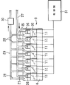
- FIG. 1 is a side view of a dampening water device for a printing press showing a first embodiment of the present invention.
- FIG. 2 is a plan view of FIG.
- FIG. 3 is a perspective view showing an example of an ink supply device used in the printing machine of the present invention.
- FIG. 4 is a block diagram showing a main part of the control device of the printing press according to the present invention.
- FIG. 5 is a side view of a wet water device for a printing press showing a second embodiment of the present invention.
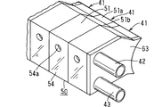
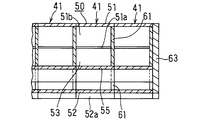
- FIG. 6 is a perspective view of a plurality of air supply boxes of the wet water device according to the second embodiment.
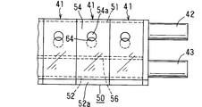
- FIG. 7 is a view of the plurality of air supply boxes in FIG. 6 as viewed from the top wall side.
- FIG. 1 is a side view of a dampening water device for a printing press showing a first embodiment of the present invention.
- FIG. 2 is a plan view of FIG.
- FIG. 3 is a perspective view showing an example
- FIG. 8 is a view of the plurality of air supply boxes in FIG. 6 as viewed from the lid side.
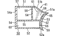
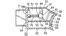
- FIG. 9 is a cross-sectional view taken along a central plane parallel to the lid of one air supply box of FIG. 10 is a cross-sectional view taken along line XX in FIG.
- FIG. 11 is a cross-sectional view taken along the line XI-XI in FIG. 12 is a view of the air supply box of FIG. 6 as viewed from the roller side.
- FIG. 13 is a side view showing a state in which the valve mechanism of the wet water device of the second embodiment is incorporated in the air supply box shown in FIG. 9.
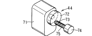
- FIG. 14 is a perspective view showing the valve mechanism.
- FIG. 15 is a schematic view showing an air passage closed state of the valve mechanism.
- FIG. 16 is a schematic diagram showing a change in the air passage open state of the valve mechanism.
- FIG. 17 is a schematic view showing a fully open state of the air passage of the valve mechanism.
- FIG. 1 the left in FIG. 1 is the front and the right is the rear.
- the left and right in FIG. 1 the left in FIG. 1 is the front and the right is the rear.
- the dampening water device (1) of the printing press includes a water tank (4) as a water source, a water source roller (5) on the water tank (4) side, and a printing plate.
- an ink form roller that supplies ink in contact with the plate surface of the plate cylinder (2)
- the ink in the ink fountain includes an ink source roller, an ink call roller, a plurality of ink kneading rollers, and The ink is transferred to the ink form roller via an ink reciprocating roller and supplied to the plate surface of the plate cylinder (2).
- the ink supplied from the inking device to the plate surface of the plate cylinder (2) is transferred directly or via another cylinder such as a rubber cylinder or a roller to a printing medium such as printing paper, and a printed matter is obtained. .
- the water in the water tank (4) passes through the water source roller (5), the water transfer rollers (7) (8) and the swim roller (6). Is supplied to the plate surface of the plate cylinder (2) as fountain solution. Since the fountain solution has a great influence on the quality of the printed matter, it has been a problem to supply it appropriately.
- the plate cylinder (2), water source roller (5), water transfer rollers (7) and (8) and swim roller (6) extend in the left-right direction (horizontal direction).
- the swim roller (6) is disposed behind the plate cylinder (2).
- the water source roller (5) is made of metal
- the swim roller (6) is made of rubber.
- the water transfer rollers (7) and (8) have one roller (7) made of metal and the other.
- the roller (8) is made of rubber.
- the water source roller (5), the water transfer rollers (7), (8), and the swim roller (6) are rotatably supported by the frame of the printing machine at both left and right ends, and are synchronized with each other by a driving device (not shown). It is continuously rotated in the direction of the arrow in FIG. 1 at a predetermined rotational speed.
- the water source roller (5) always rotates with its lower part immersed in the water in the water tank (4), and the water roller (6) always rotates while in contact with the plate surface of the plate cylinder (2). ing.
- the dampening water amount adjusting device (9) has a plurality of air blowing portions (11) arranged side by side in the axial direction of the water transfer roller (8), and the rollers from each air blowing portion (11) By controlling the air spray amount separately, the distribution in the axial direction of the dampening water transfer roller (8) is controlled. Thereby, the amount of dampening water in the axial direction of the swim roller (6) is adjusted by the position in the width direction of the printed matter.
- the air blowing section (11) is disposed between the pair of side walls (21) and (22) whose tip is in contact with the outer periphery of the water transfer roller (8) and the pair of side walls (21) and (22). And a passage forming block (23) for forming an air passage (24) between the outer periphery of the water transfer roller (8) and the pair of side walls (21) and (22).
- the passage forming block (23) has a pair of curved opposing surfaces (23a) facing the outer periphery of the water transfer roller (8) at a predetermined interval and a pair of side walls (21), (22). These planar opposing surfaces (23b) and (23c) are provided.
- the passage (24a) formed by the one side wall (21) and the one planar opposing surface (23b) has an air inlet pipe (25) via a flow rate adjusting valve (valve mechanism) (26) at its opening. ) Is connected to form an introduction-side passage (24a).
- the other end of the air introduction pipe (25) is connected to the introduction side connection pipe (27), and the introduction side connection pipe (27) is connected to a high-pressure air supply source (not shown).
- the flow rate adjustment valve (26) is, for example, a rotary valve such as a ball valve, and is an electric valve that can electrically control the degree of opening and closing of the flow path. It is possible to shift from a state in which all of (24) is closed to a state in which a part of the air passage (24) is closed and further to a state in which all of the air passage (24) is opened (the reverse transition is also possible) Any valve mechanism may be used.
- the passage (24a) formed by the other side wall (22) and the other planar opposing surface (23c) has one end of an air discharge pipe (28) connected to the opening thereof, so that the discharge side It is a passage (24c).
- the other end of the air discharge pipe (28) is connected to a discharge side connection pipe (29), and the discharge side connection pipe (29) is a suction fan (forcibly sucking air in the discharge side connection pipe (29)). (Suction device) (30).
- the introduction side passage (24a) and the discharge side passage (24c) are parallel to each other, and both extend in a direction perpendicular to the line parallel to the axial direction of the water transfer roller (8).
- the passage (24b) formed by the outer periphery of the water transfer roller (8) and the curved opposing surface (23a) is located between the introduction side passage (24a) and the discharge side passage (24c) and is used for water transfer.
- a cross section in which air flows along the outer peripheral surface of the water transfer roller (8) in the same direction as the rotation direction of the roller (8) is an arc-shaped air blowing passage (24b).
- air flows into the air blowing part (11) from the introduction side passage (24a) formed by the one side wall (21) and the one planar opposing surface (23b), and the water transfer roller After flowing through the air blowing passage (24b) formed by the outer periphery of (8) and the curved opposing surface (23a), it was formed between the other side wall and the other planar opposing surface.
- a substantially U-shaped air passage (24) flowing out from the discharge side passage (24c) is formed.
- the plurality of air blowing portions (11) are provided so as to be adjacent to each other. However, since the air passage (24) is formed as described above, the air blowing portions (11) are blown out from the substantially U-shaped air passage (24). Air does not interfere with each other.
- the opening / closing amount of the flow control valve (26) is controlled by the control panel (control device) (31).
- This control device (31) is based on the data of the ink supply device that controls the ink amount, the feed speed of the printed matter, the rotational speed of each roller (5) (6) (7) (8), etc. Controls the opening / closing amount of 26).
- the amount of air blowing increases or decreases.
- the amount of dampening water can be decreased by increasing the amount of air sprayed, and the amount of dampening water can be increased by decreasing the amount of air sprayed.
- the amount of dampening water supplied to the plate surface of the plate cylinder (2) from the swim roller (6) was adjusted individually. It is adjusted by the air blowing part (11). For this reason, the amount of dampening water in the width direction of the printed matter can be adjusted according to the width and pattern area of the printed matter. Accordingly, the amount of dampening water at the axial position of the swim roller (6) corresponding to the width direction of the printed matter is adjusted in accordance with the ink amount control in the width direction of the printed matter, and according to the supply of a preferable ink amount A preferable dampening water can be supplied.
- the air flow direction is the same as the rotation direction of the water transfer roller (8), but the air flow direction is opposite to the rotation direction of the water transfer roller (8).
- the direction is preferred. That is, an air introduction unit including an air introduction pipe (25), a flow rate adjusting valve (26) and an introduction side connection pipe (27), an air discharge pipe (28), a discharge side connection pipe (29), and a suction fan (suction device) It is preferable to replace the air discharge unit consisting of (30).
- the ink supply device (90) of the printing press in which the dampening device (1) is used for example, as shown in FIG. 3, close to the ink fountain roller (92) constituting the ink fountain (91), A plurality of ink call rollers (93) divided in the length direction of the ink fountain roller (92) are arranged, and each ink call roller (93) is in contact with the ink fountain roller (92) and the ink fountain roller. It is possible to individually switch to a non-calling position that contacts the ink kneading roller (94) apart from the (92), and the position of the required ink calling roller (93) is set at every calling timing at a predetermined interval.
- the ink fountain roller (92) is controlled by controlling the rotation angle of the ink fountain roller (92) until it leaves the ink fountain roller (92) for each ink call roller (93). To the ink call roller (93) It is adapted to control the (contact length in one rotation) circumference of the ink out.
- the ink amount is controlled for each ink call roller (93) in accordance with the optimum ink amount depending on the position in the width direction depending on the pattern of the printed matter.
- the accuracy of quantity control is improved.
- FIG. 4 shows a control device (31) of the dampening water device (1).
- the control device (31) of the fountain solution device (1) is connected to the ink supply device control device (10) via a relay converter, and the ink control data (graph) in the ink supply device control device (10) is connected to the ink supply device control device (10). Value and other necessary data) are received from the ink supply device controller (10) to control the amount of dampening water.
- the contact rotation angle is controlled by outputting a switching command (contact command) to the calling position for the ink calling roller (93) and then switching to the non-calling position (contact command).
- a switching command contact command
- the non-calling position contact command
- the position of the ink calling roller (93) is switched by turning on / off the switching valve (95).
- the amount of ink supplied to the printing surface is adjusted by the position in the width direction.
- the control device for the ink supply device (10) includes a target value setting means (96) for setting a target value for the ink amount, and a switching valve according to the target value for the ink amount set in the target value setting means (96). And a switching valve on / off calculating means (97) for determining the on / off time of (95).
- the picture area ratio is read using a picture area reading device, and a graph value corresponding to the ink supply amount is calculated. It is converted into the contact length with the roller (92) and used to control ink supply.
- the graph value is the target value of the ink amount indicating how much ink of the predetermined color is used for each ink calling roller (93).
- 0% is the maximum.
- 100% is displayed in%. Accordingly, 30%, 40%, 10%, and the like are set according to the pattern area of the portion corresponding to each ink calling roller (93).
- a graph value (that is, a target value) for each color is set for each ink calling roller (93), and the first to Nth calling rollers (93) are set according to this target value.
- the target value of the contact length is obtained.
- the target value of the contact length of the first to Nth calling rollers (93) is set to the on / off time of the first to Nth switching valves (95).
- the converted on-off signals necessary for the first to Nth switching valves (95) are transmitted.
- control is performed so that an optimum contact length is obtained for each of the first to Nth calling rollers (93).
- the density of each color is controlled to be constant at any position.
- Each flow rate adjustment valve (26) of the wet water device (1) is driven by a servo motor (32), for example.
- the control device (31) of the wet water device (1) is provided with motor rotation amount calculation means (33).
- the control device (31) of the dampening water device (1) does not include a dedicated target value setting means, and is connected to the ink supply device control device (10) via a relay converter or the like.
- Ink supply amount control data such as the target value of the contact length of the first to Nth calling rollers (93) or the target value of the pattern area used for the calculation is received from the ink supply device controller (10). .
- the opening / closing amounts of the first to Nth flow rate adjusting valves (26) are determined from the ink supply amount control data corresponding to the first to Nth calling rollers (93).
- the motor rotation amounts of the corresponding first to N-th servo motors (32) are obtained, whereby an optimum air flow rate is obtained for each of the first to N-th flow rate adjusting valves (26).
- FIG. 5 to FIG. 18 show a second embodiment of the wet water device for a printing press according to the present invention.
- the second embodiment is different from the first embodiment in the dampening water amount adjusting device, and the dampening water amount adjusting device (40) will be described in detail below.
- the dampening water amount adjusting device (40) of this embodiment supplies air to a plurality of air supply boxes (41) arranged side by side and one of the air supply boxes (41).
- each air supply box (41) passes through the communication hole (64) from the first chamber (air supply chamber) (57).
- the third chamber (air blowing passage) that enters the two chambers (air blowing section) (58), and the air blown from the air blowing port (65) of the air blowing section (58) runs along the water transfer roller (8) ( 59), a substantially U-shaped air passage is formed through the air feed port (66) leading to the fourth chamber (air discharge chamber) (60), and the opening of the communication hole (64)
- the amount is adjusted by a valve mechanism (44).
- each air supply box (41) has a pair of side walls (a first side wall (51) and a second side wall (52) with one end facing the water transfer roller (8). )), A curved bottom wall (53) connecting the vicinity of one end of the pair of side walls (51) and (52), and a flat shape connecting the other ends of the pair of side walls (51) and (52). And a casing (50) that is open on both the left and right sides.
- a first bent portion (51a) close to the water transfer roller (8) and a second bent portion (51b) connected to the first bent portion (51a) are provided at one end of the first side wall (51).
- only one first bent portion (52a) is provided at one end of the second side wall (52).
- the first bent portion (51a) (52a) of each side wall (51) (52) has a water transfer roller so that a slight gap of about 0.5 mm exists between the water transfer roller (8).
- the bottom wall (53) faces the water transfer roller (8) so that an interval allowing air to pass by about 2 mm exists between the water transfer roller (8).
- the top wall (54) is provided with a motor mounting through hole (54a).
- the casing (50) is arranged in parallel with the side walls (51) and (52) to divide the inside of the casing (50) into two parts, a first side wall side part and a second side wall side part.
- the first side wall (51) and the first partition wall (55) are arranged so as to be orthogonal to them, and the first side wall side portion in the casing (50) is the top wall side portion.
- a second partition wall (56) for partitioning into two parts, a bottom wall side portion.
- the air supply box (41) includes a portion on the top wall side of the first side wall (51), a portion on the first side wall side of the top wall (54), and a portion on the top wall side of the first partition wall (55). And the first chamber (57) surrounded by the second partition wall (56), the bottom wall portion of the first side wall (51), the second partition wall (56), and the bottom of the first partition wall (55).
- a second chamber (58) surrounded by a wall side portion and a first side wall side portion of the bottom wall (53); a bottom wall (53); a first bent portion (51a) of the first side wall (51);
- the third chamber (59) surrounded by the first bent portion (52a) of the second side wall (52), the second side wall (52), the portion of the top wall (54) on the second side wall side, the first partition wall (55) and a fourth chamber (60) surrounded by a portion of the bottom wall (53) on the second side wall side.
- the fourth chamber (60) is formed in an arc shape along the outer peripheral surface of the water transfer roller (8) when viewed from the left-right direction.
- the boundary between the left and right air supply boxes (41) includes a first partition (61) that partitions adjacent second chambers (58) and a second partition that partitions adjacent third chambers (60) ( 62).
- the left opening of the air supply box (41) at the left end is closed by the left lid (63).
- the left lid (63) has a through hole (63a) communicating with the first chamber (57) of the air supply box (41) at the left end and the fourth chamber (60) of the air supply box (41) at the left end. Is provided with a through hole (63b) communicating therewith.
- One end of an air supply pipe (42) is connected to the edge of the through hole (63a) communicating with the first chamber (57), and the other end of the air supply pipe (42) is an air source (not shown). It is connected to the.
- One end of the air discharge pipe (43) is connected to the edge of the through hole (63b) communicating with the fourth chamber (60), and the other end of the air discharge pipe (43) is a suction fan, a vacuum pump, etc. Connected to a suction device (not shown).
- a communication hole (64) having a circular cross section is provided to communicate the first chamber (57) and the second chamber (58).
- a portion of the bottom wall (53) on the first side wall side has an air outlet (65) having a rectangular cross section that blows air in the second chamber (58) toward the roller so as to contact the first side wall (51). Is provided.
- a portion of the bottom wall (53) on the second side wall side has an air feed port (66) having a rectangular cross section for sending the air blown to the rollers into the fourth chamber (60) so as to contact the second side wall (52). Is provided.
- the air in the first chamber (57) (that is, the air supply chamber (57)) communicating with the air supply pipe (42) is contained.
- Passes through the communication hole (64) of the second partition wall (56) flows into the second chamber (58) (that is, the air blowing part (58)), and flows into the second chamber (58) to blow out the air from the second chamber (58).
- the water transfer roller exits from the mouth (65) (ie, the air outlet (65)), enters the third chamber (60) (ie, the air blowing passage (59)), and moves into the third chamber (60). It passes along the outer peripheral surface of (8) and flows into the fourth chamber (60) (that is, the air discharge chamber (60)) that communicates from the air feed port (66) to the air discharge pipe (43).
- a U-shaped air passage is formed.
- the first chambers (57) and the fourth chambers (60) of each air supply box (41) are in communication with each other, and the first chamber (57 of the air supply box at the left end is connected by the air supply pipe (42). ) Is sequentially supplied into the first chamber (57) of each air supply box, and the air in the fourth chamber (60) of each air supply box is left-handed by the air discharge pipe (43). It is extracted through the fourth chamber (60) of the air supply box.
- the air supply box (41) can be obtained, for example, as a synthetic resin molded product in which the partition walls (61) and (62) are integrally provided, and the air supply boxes (41) are bonded to each other by adhesion, welding, or the like. At the same time, by fixing the lid (63) to both ends by adhesion, welding or the like, it is possible to obtain an air supply unit in which a large number of air supply boxes (41) are integrated and both ends are closed.
- valve mechanism (44) arranged in each air supply box (41) will be described with reference to FIGS.
- the top wall side of the casing (50) of the air supply box (41) is referred to as the upper side
- the bottom wall side is referred to as the lower side.
- the valve mechanism (44) increases or decreases the amount of air passing through the communication hole (64) by increasing or decreasing the opening amount of the communication hole (64) of the second partition wall (56), and is shown in FIGS.
- Servo motor (71) attached to the top wall (54) of the casing (50) provided with the through hole (54a) and rotatably attached to the lower surface of the top wall (54) of the casing (50)
- a circular rotating plate (72) rotated by a servo motor (71), an eccentric shaft (73) fixed to the outer peripheral edge of the rotating plate (72) and extending downward, and a lower end of the eccentric shaft (73)
- the plug body (74) has a cylindrical shape, and a cylindrical recess is formed on the upper surface thereof, into which the lower end of the eccentric shaft (73) is fitted.
- the cross section of the plug (74) is a circle having a diameter larger than the diameter of the communication hole (64).
- the upper surface of the compression coil spring (75) is received by the lower surface of the rotating plate (72), and the lower surface thereof is received by the upper surface of the plug (74).
- FIG. 15 shows the air passage closed state in which the plug (74) of the valve mechanism (44) closes the communication hole (64). From this state, when the rotating plate (72) is rotated by the servo motor (71), as shown in FIG. 16, the axis of the eccentric shaft (73) rotates as the rotating plate (72) rotates. It moves along the circumference centered on the central axis (O) of the plate (72). This circumference passes through the center line of the communication hole (64).
- each air supply box (41) forms an air blowing passageway (59) through which air flows along the outer peripheral surface of the water transfer roller (8). Flows smoothly and can be adjusted accurately.
- dampening water amount adjusting devices (9) and (40) are provided on the water transfer roller (8), but may be provided on the water source roller (5) instead.
- the dampening water since the dampening water can be supplied appropriately in the dampening water device of the printing press, it can contribute to the improvement of the printing performance.
Landscapes
- Engineering & Computer Science (AREA)
- Mechanical Engineering (AREA)
- Inking, Control Or Cleaning Of Printing Machines (AREA)
- Rotary Presses (AREA)
- Delivering By Means Of Belts And Rollers (AREA)
Abstract
Description
Claims (6)
- 水源側の1または複数のローラと、印刷部側のローラと、湿し水量調整装置とを備え、水源側のローラから印刷部側のローラに湿し水が転写されるようになされている印刷機の湿水装置であって、
湿し水量調整装置は、水源側のいずれかのローラの軸方向に複数並んで配置され、ローラへのエア吹付け量がそれぞれ別個に弁機構によって調整可能とされたエア吹出し部を備えており、各エア吹出し部は、ローラの外周面に沿ってエアを流すエア吹付け通路を有していることを特徴とする印刷機の湿水装置。 - 各エア吹出し部は、流量制御弁を介してエア導入管に接続されていることを特徴とする請求項1の印刷機の湿水装置。
- 各エア吹出し部は、吸引装置に接続されたエア排出管に接続されていることを特徴とする請求項1の印刷機の湿水装置。
- 湿し水量調整装置は、ローラの軸方向に並んで配置されてそれぞれが1つのエア吹出し部を形成する複数のエア供給ボックスと、いずれかのエア供給ボックスにエアを供給するエア供給管と、いずれかのエア供給ボックスからエアを抜き出すエア排出管とを備え、
各エア供給ボックスは、隣り合うエア供給ボックスに連通してエア供給管を介してエアが供給されるエア供給室と、隣り合うエア供給ボックスに連通してエア排出管を介してエアが排出されるエア排出室と、隣り合うエア供給ボックスと隔壁によって仕切られており、エア供給室内のエアをローラの外周面に沿って通過させ、エア排出室内に送るエア通路とを有しており、
エア通路途中に、エア量を増減させる弁機構が設けられていることを特徴とする請求項1の印刷機の湿水装置。 - 各エア供給ボックスのエア供給室に、連通孔が形成された仕切り壁が設けられており、弁機構は、連通孔の全部を閉鎖する位置、連通孔の一部を閉鎖する位置および連通孔の全部を開放する位置に移動可能な栓体と、栓体を移動させる栓体駆動装置とを備えていることを特徴とする請求項4の印刷機の湿水装置。
- インキ供給装置および湿水装置を備えた印刷機であって、
インキ供給装置は、インキ壺を構成するインキ壺ローラに近接して、インキ壺ローラの長さ方向に分割された複数のインキ呼び出しローラが配置され、各インキ呼び出しローラは、インキ壺ローラに接触する呼び出し位置とインキ壺ローラから離れる非呼び出し位置とに個別に切換弁のオン・オフによって切り換えられるようになされており、
インキ供給装置の制御装置は、インキ量の目標値が設定される目標値設定手段と、目標値設定手段に設定されたインキ量の目標値に応じて切換弁のオン・オフの時間を決定する切換弁オン・オフ演算手段とを備え、
湿水装置が請求項1から5までに記載のいずれかのものとされるとともに、そのエア吹出し部の数がインキ呼び出しローラの数と同じとされて、各エア吹出し部は、駆動装置を駆動させて吹き出し量が調整されるものとされており、
湿水装置の制御装置は、インキ供給装置の制御装置の目標値設定手段に蓄えられている目標値を使用して、駆動装置を制御することを特徴とする印刷機。
Priority Applications (9)
| Application Number | Priority Date | Filing Date | Title |
|---|---|---|---|
| KR1020167022700A KR20180015556A (ko) | 2015-06-03 | 2016-05-13 | 인쇄기의 습수 장치 및 이것을 구비한 인쇄기 |
| EP16751140.1A EP3132933B1 (en) | 2015-06-03 | 2016-05-13 | Dampening water apparatus for printing machines and printing machine equipped with same |
| CN201680000795.3A CN106414076B (zh) | 2015-06-03 | 2016-05-13 | 印刷机的润湿装置及具有该润湿装置的印刷机 |
| ES16751140T ES2773061T3 (es) | 2015-06-03 | 2016-05-13 | Aparato de agua humectante de para máquinas de impresión y una máquina de impresión equipada con el mismo |
| MYPI2017700349A MY184966A (en) | 2015-06-03 | 2016-05-13 | Dampening apparatus for printer and printer having the same |
| MX2017001346A MX2017001346A (es) | 2015-06-03 | 2016-05-13 | Aparato humectante para impresora e impresora que tiene el mismo. |
| JP2017521772A JP6688510B2 (ja) | 2015-06-03 | 2016-05-13 | 印刷機の湿水装置およびこれを備えた印刷機 |
| US15/122,181 US10016968B2 (en) | 2015-06-03 | 2016-05-13 | Dampening apparatus for printer and printer having the same |
| BR112017002642A BR112017002642A2 (pt) | 2015-06-03 | 2016-05-13 | aparelho de amortecimento para uma impressora e impressora tendo o mesmo |
Applications Claiming Priority (4)
| Application Number | Priority Date | Filing Date | Title |
|---|---|---|---|
| JP2015112932 | 2015-06-03 | ||
| JP2015-112932 | 2015-06-03 | ||
| JP2015226386 | 2015-11-19 | ||
| JP2015-226386 | 2015-11-19 |
Publications (1)
| Publication Number | Publication Date |
|---|---|
| WO2016194583A1 true WO2016194583A1 (ja) | 2016-12-08 |
Family
ID=57442321
Family Applications (1)
| Application Number | Title | Priority Date | Filing Date |
|---|---|---|---|
| PCT/JP2016/064312 WO2016194583A1 (ja) | 2015-06-03 | 2016-05-13 | 印刷機の湿水装置およびこれを備えた印刷機 |
Country Status (11)
| Country | Link |
|---|---|
| US (1) | US10016968B2 (ja) |
| EP (1) | EP3132933B1 (ja) |
| JP (1) | JP6688510B2 (ja) |
| KR (1) | KR20180015556A (ja) |
| CN (1) | CN106414076B (ja) |
| BR (1) | BR112017002642A2 (ja) |
| ES (1) | ES2773061T3 (ja) |
| MX (1) | MX2017001346A (ja) |
| MY (1) | MY184966A (ja) |
| TW (1) | TWI685427B (ja) |
| WO (1) | WO2016194583A1 (ja) |
Families Citing this family (1)
| Publication number | Priority date | Publication date | Assignee | Title |
|---|---|---|---|---|
| CN108638638A (zh) * | 2018-06-27 | 2018-10-12 | 惠州市国鹏印刷股份有限公司 | 用于印刷机的防渗水斗棍 |
Citations (8)
| Publication number | Priority date | Publication date | Assignee | Title |
|---|---|---|---|---|
| JPS5382512A (en) * | 1976-12-25 | 1978-07-21 | Tsunekichi Kushishitamachi | Device for supplying dampening water to printer |
| JPS6360324U (ja) * | 1986-10-06 | 1988-04-21 | ||
| JPH0411637U (ja) * | 1990-05-21 | 1992-01-30 | ||
| JPH0671863A (ja) * | 1992-01-10 | 1994-03-15 | Ikeda Sadami | 印刷機のインキ供給装置 |
| JPH1158672A (ja) | 1997-08-18 | 1999-03-02 | Toppan Printing Co Ltd | 湿し水供給装置 |
| JP2002240245A (ja) * | 2001-02-20 | 2002-08-28 | Toppan Printing Co Ltd | 湿し水制御装置およびこの装置を用いた湿し水制御方法 |
| JP2005262785A (ja) | 2004-03-22 | 2005-09-29 | Aimaa Planning Kk | 印刷機の湿水装置および水移し用分割ローラ装置 |
| JP2008105190A (ja) | 2006-10-23 | 2008-05-08 | Miyakoshi Printing Machinery Co Ltd | オフセット印刷機の湿し水装置 |
Family Cites Families (12)
| Publication number | Priority date | Publication date | Assignee | Title |
|---|---|---|---|---|
| JPS5957755A (ja) * | 1982-09-29 | 1984-04-03 | Toppan Printing Co Ltd | 湿し水装置 |
| JPH0633604B2 (ja) * | 1986-09-01 | 1994-05-02 | 株式会社大林組 | 土砂水中投入方法 |
| IT1211266B (it) * | 1987-08-17 | 1989-10-12 | Grapho Eng Srl | Sistema di bagnatura continua a regolazione automatica per macchine da stampa offset |
| CA2156005A1 (en) * | 1994-08-16 | 1996-02-17 | John W. Bird | Multiple color offset press utilizing aqueous ink and waterless printing plates with interstation drying and extraction |
| CN1159983A (zh) * | 1996-03-15 | 1997-09-24 | 耿志刚 | 胶印机印版的气态输水润湿方法和装置 |
| JP2945348B2 (ja) * | 1997-04-01 | 1999-09-06 | 株式会社小森コーポレーション | 印刷機の給水装置 |
| DE19819387B4 (de) * | 1997-05-02 | 2005-12-22 | Heidelberger Druckmaschinen Ag | Verfahren und Vorrichtung zur Saugluftsteuerung |
| US6374732B1 (en) * | 2000-06-05 | 2002-04-23 | Frank Perretta | Dampener for use in lithographic presses |
| US20030172818A1 (en) * | 2002-03-13 | 2003-09-18 | Marcel Motard | Dampening system for a printing press |
| CN2838953Y (zh) * | 2005-10-11 | 2006-11-22 | 范道生 | 一种胶印机的润湿装置 |
| JP5069523B2 (ja) * | 2007-08-31 | 2012-11-07 | 株式会社加貫ローラ製作所 | オフセット印刷機の給水装置 |
| JP6360324B2 (ja) | 2014-02-20 | 2018-07-18 | 株式会社イシダ | 表示システム |
-
2016
- 2016-05-13 KR KR1020167022700A patent/KR20180015556A/ko unknown
- 2016-05-13 US US15/122,181 patent/US10016968B2/en not_active Expired - Fee Related
- 2016-05-13 MX MX2017001346A patent/MX2017001346A/es unknown
- 2016-05-13 MY MYPI2017700349A patent/MY184966A/en unknown
- 2016-05-13 BR BR112017002642A patent/BR112017002642A2/pt not_active IP Right Cessation
- 2016-05-13 EP EP16751140.1A patent/EP3132933B1/en active Active
- 2016-05-13 WO PCT/JP2016/064312 patent/WO2016194583A1/ja active Application Filing
- 2016-05-13 CN CN201680000795.3A patent/CN106414076B/zh not_active Expired - Fee Related
- 2016-05-13 ES ES16751140T patent/ES2773061T3/es active Active
- 2016-05-13 JP JP2017521772A patent/JP6688510B2/ja not_active Expired - Fee Related
- 2016-06-02 TW TW105117314A patent/TWI685427B/zh not_active IP Right Cessation
Patent Citations (8)
| Publication number | Priority date | Publication date | Assignee | Title |
|---|---|---|---|---|
| JPS5382512A (en) * | 1976-12-25 | 1978-07-21 | Tsunekichi Kushishitamachi | Device for supplying dampening water to printer |
| JPS6360324U (ja) * | 1986-10-06 | 1988-04-21 | ||
| JPH0411637U (ja) * | 1990-05-21 | 1992-01-30 | ||
| JPH0671863A (ja) * | 1992-01-10 | 1994-03-15 | Ikeda Sadami | 印刷機のインキ供給装置 |
| JPH1158672A (ja) | 1997-08-18 | 1999-03-02 | Toppan Printing Co Ltd | 湿し水供給装置 |
| JP2002240245A (ja) * | 2001-02-20 | 2002-08-28 | Toppan Printing Co Ltd | 湿し水制御装置およびこの装置を用いた湿し水制御方法 |
| JP2005262785A (ja) | 2004-03-22 | 2005-09-29 | Aimaa Planning Kk | 印刷機の湿水装置および水移し用分割ローラ装置 |
| JP2008105190A (ja) | 2006-10-23 | 2008-05-08 | Miyakoshi Printing Machinery Co Ltd | オフセット印刷機の湿し水装置 |
Also Published As
| Publication number | Publication date |
|---|---|
| EP3132933B1 (en) | 2020-01-08 |
| JP6688510B2 (ja) | 2020-04-28 |
| CN106414076A (zh) | 2017-02-15 |
| US10016968B2 (en) | 2018-07-10 |
| CN106414076B (zh) | 2020-04-21 |
| MY184966A (en) | 2021-04-30 |
| EP3132933A4 (en) | 2018-02-14 |
| BR112017002642A2 (pt) | 2017-12-05 |
| EP3132933A1 (en) | 2017-02-22 |
| JPWO2016194583A1 (ja) | 2018-03-22 |
| US20170151771A1 (en) | 2017-06-01 |
| TWI685427B (zh) | 2020-02-21 |
| MX2017001346A (es) | 2017-05-03 |
| TW201704038A (zh) | 2017-02-01 |
| KR20180015556A (ko) | 2018-02-13 |
| ES2773061T3 (es) | 2020-07-09 |
Similar Documents
| Publication | Publication Date | Title |
|---|---|---|
| JP4417875B2 (ja) | エア流量調整装置 | |
| WO2016194583A1 (ja) | 印刷機の湿水装置およびこれを備えた印刷機 | |
| JP6211837B2 (ja) | 印刷機用のパウダー装置 | |
| JP2000118051A (ja) | シガレット被覆紙テ―プ用印刷機構に液状の印刷インキを供給するための装置 | |
| JP2011508111A (ja) | 抄紙機若しくはその類の乾燥セクションにおける負圧制御装置及び方法 | |
| JP2016112887A (ja) | インク式印刷機械 | |
| CN103085468B (zh) | 用于给印刷页张撒布粉末的设备 | |
| JPH1034882A (ja) | 枚葉紙を案内する印刷機胴のための枚葉紙ガイド装置 | |
| JP2964246B1 (ja) | キーレス印刷機のインキ貯留装置 | |
| CN103909736A (zh) | 液体喷射设备和方法 | |
| WO2017200084A1 (ja) | 印刷機の湿水装置 | |
| JP6841050B2 (ja) | 搬送装置及び印刷装置 | |
| CN108327401B (zh) | 印刷装置及输送装置 | |
| JP2016221919A (ja) | 印刷機の湿水装置 | |
| JP6297214B2 (ja) | 印刷部の湿し媒体案内におけるプロフィールの調整および/または変更 | |
| JP6930321B2 (ja) | 液体吐出装置 | |
| JP2001293843A (ja) | 枚葉印刷機のシートガイド装置 | |
| JP2003220689A (ja) | 加工処理機のための可動ガイド面を備えた枚葉紙ガイド装置 | |
| JP2020100100A (ja) | 印刷機 | |
| JP3853468B2 (ja) | 版かぶり防止装置およびグラビア印刷機 | |
| JP3802549B2 (ja) | 空気開閉装置 | |
| US5706723A (en) | Apparatus for controlling nozzle movement in nozzle-type dampening systems | |
| JP2018114709A (ja) | 印刷装置 | |
| JP7024268B2 (ja) | 液体吐出装置 | |
| JP2005239291A (ja) | 空気式給紙装置 |
Legal Events
| Date | Code | Title | Description |
|---|---|---|---|
| ENP | Entry into the national phase |
Ref document number: 20167022700 Country of ref document: KR Kind code of ref document: A |
|
| REEP | Request for entry into the european phase |
Ref document number: 2016751140 Country of ref document: EP |
|
| WWE | Wipo information: entry into national phase |
Ref document number: 2016751140 Country of ref document: EP |
|
| WWE | Wipo information: entry into national phase |
Ref document number: 15122181 Country of ref document: US |
|
| ENP | Entry into the national phase |
Ref document number: 2017521772 Country of ref document: JP Kind code of ref document: A |
|
| 121 | Ep: the epo has been informed by wipo that ep was designated in this application |
Ref document number: 16751140 Country of ref document: EP Kind code of ref document: A1 |
|
| WWE | Wipo information: entry into national phase |
Ref document number: MX/A/2017/001346 Country of ref document: MX |
|
| REG | Reference to national code |
Ref country code: BR Ref legal event code: B01A Ref document number: 112017002642 Country of ref document: BR |
|
| ENP | Entry into the national phase |
Ref document number: 112017002642 Country of ref document: BR Kind code of ref document: A2 Effective date: 20170209 |
|
| NENP | Non-entry into the national phase |
Ref country code: DE |