WO2016194112A1 - 単焦点光学系及びそれを備えた光学装置 - Google Patents
単焦点光学系及びそれを備えた光学装置 Download PDFInfo
- Publication number
- WO2016194112A1 WO2016194112A1 PCT/JP2015/065800 JP2015065800W WO2016194112A1 WO 2016194112 A1 WO2016194112 A1 WO 2016194112A1 JP 2015065800 W JP2015065800 W JP 2015065800W WO 2016194112 A1 WO2016194112 A1 WO 2016194112A1
- Authority
- WO
- WIPO (PCT)
- Prior art keywords
- lens
- optical system
- subgroup
- group
- focus optical
- Prior art date
Links
Images


Classifications
-
- G—PHYSICS
- G02—OPTICS
- G02B—OPTICAL ELEMENTS, SYSTEMS OR APPARATUS
- G02B9/00—Optical objectives characterised both by the number of the components and their arrangements according to their sign, i.e. + or -
- G02B9/64—Optical objectives characterised both by the number of the components and their arrangements according to their sign, i.e. + or - having more than six components
-
- G—PHYSICS
- G02—OPTICS
- G02B—OPTICAL ELEMENTS, SYSTEMS OR APPARATUS
- G02B13/00—Optical objectives specially designed for the purposes specified below
- G02B13/001—Miniaturised objectives for electronic devices, e.g. portable telephones, webcams, PDAs, small digital cameras
- G02B13/0055—Miniaturised objectives for electronic devices, e.g. portable telephones, webcams, PDAs, small digital cameras employing a special optical element
- G02B13/006—Miniaturised objectives for electronic devices, e.g. portable telephones, webcams, PDAs, small digital cameras employing a special optical element at least one element being a compound optical element, e.g. cemented elements
-
- G—PHYSICS
- G02—OPTICS
- G02B—OPTICAL ELEMENTS, SYSTEMS OR APPARATUS
- G02B13/00—Optical objectives specially designed for the purposes specified below
- G02B13/001—Miniaturised objectives for electronic devices, e.g. portable telephones, webcams, PDAs, small digital cameras
- G02B13/0015—Miniaturised objectives for electronic devices, e.g. portable telephones, webcams, PDAs, small digital cameras characterised by the lens design
- G02B13/002—Miniaturised objectives for electronic devices, e.g. portable telephones, webcams, PDAs, small digital cameras characterised by the lens design having at least one aspherical surface
- G02B13/0045—Miniaturised objectives for electronic devices, e.g. portable telephones, webcams, PDAs, small digital cameras characterised by the lens design having at least one aspherical surface having five or more lenses
-
- G—PHYSICS
- G02—OPTICS
- G02B—OPTICAL ELEMENTS, SYSTEMS OR APPARATUS
- G02B13/00—Optical objectives specially designed for the purposes specified below
- G02B13/04—Reversed telephoto objectives
-
- G—PHYSICS
- G02—OPTICS
- G02B—OPTICAL ELEMENTS, SYSTEMS OR APPARATUS
- G02B13/00—Optical objectives specially designed for the purposes specified below
- G02B13/16—Optical objectives specially designed for the purposes specified below for use in conjunction with image converters or intensifiers, or for use with projectors, e.g. objectives for projection TV
-
- G—PHYSICS
- G02—OPTICS
- G02B—OPTICAL ELEMENTS, SYSTEMS OR APPARATUS
- G02B7/00—Mountings, adjusting means, or light-tight connections, for optical elements
- G02B7/02—Mountings, adjusting means, or light-tight connections, for optical elements for lenses
- G02B7/04—Mountings, adjusting means, or light-tight connections, for optical elements for lenses with mechanism for focusing or varying magnification
-
- H—ELECTRICITY
- H04—ELECTRIC COMMUNICATION TECHNIQUE
- H04N—PICTORIAL COMMUNICATION, e.g. TELEVISION
- H04N23/00—Cameras or camera modules comprising electronic image sensors; Control thereof
- H04N23/50—Constructional details
- H04N23/54—Mounting of pick-up tubes, electronic image sensors, deviation or focusing coils
-
- G—PHYSICS
- G02—OPTICS
- G02B—OPTICAL ELEMENTS, SYSTEMS OR APPARATUS
- G02B21/00—Microscopes
- G02B21/36—Microscopes arranged for photographic purposes or projection purposes or digital imaging or video purposes including associated control and data processing arrangements
-
- G—PHYSICS
- G02—OPTICS
- G02B—OPTICAL ELEMENTS, SYSTEMS OR APPARATUS
- G02B5/00—Optical elements other than lenses
- G02B5/005—Diaphragms
-
- G—PHYSICS
- G02—OPTICS
- G02B—OPTICAL ELEMENTS, SYSTEMS OR APPARATUS
- G02B7/00—Mountings, adjusting means, or light-tight connections, for optical elements
- G02B7/02—Mountings, adjusting means, or light-tight connections, for optical elements for lenses
- G02B7/021—Mountings, adjusting means, or light-tight connections, for optical elements for lenses for more than one lens
-
- G—PHYSICS
- G03—PHOTOGRAPHY; CINEMATOGRAPHY; ANALOGOUS TECHNIQUES USING WAVES OTHER THAN OPTICAL WAVES; ELECTROGRAPHY; HOLOGRAPHY
- G03B—APPARATUS OR ARRANGEMENTS FOR TAKING PHOTOGRAPHS OR FOR PROJECTING OR VIEWING THEM; APPARATUS OR ARRANGEMENTS EMPLOYING ANALOGOUS TECHNIQUES USING WAVES OTHER THAN OPTICAL WAVES; ACCESSORIES THEREFOR
- G03B21/00—Projectors or projection-type viewers; Accessories therefor
- G03B21/14—Details
- G03B21/147—Optical correction of image distortions, e.g. keystone
-
- H—ELECTRICITY
- H04—ELECTRIC COMMUNICATION TECHNIQUE
- H04N—PICTORIAL COMMUNICATION, e.g. TELEVISION
- H04N23/00—Cameras or camera modules comprising electronic image sensors; Control thereof
- H04N23/50—Constructional details
- H04N23/55—Optical parts specially adapted for electronic image sensors; Mounting thereof
-
- H—ELECTRICITY
- H04—ELECTRIC COMMUNICATION TECHNIQUE
- H04N—PICTORIAL COMMUNICATION, e.g. TELEVISION
- H04N23/00—Cameras or camera modules comprising electronic image sensors; Control thereof
- H04N23/60—Control of cameras or camera modules
- H04N23/63—Control of cameras or camera modules by using electronic viewfinders
- H04N23/631—Graphical user interfaces [GUI] specially adapted for controlling image capture or setting capture parameters
Definitions
- the present invention relates to a single focus optical system and an optical apparatus including the same.
- An example of focus in an imaging optical system with a large aperture ratio is focus on a telephoto lens.
- a conventional telephoto lens a telephoto lens constituted by a first lens group having a positive refractive power, a second lens group having a negative refractive power, and a third lens group having a positive refractive power in order from the object.
- the second lens group moves.
- the aberration variation can be reduced over a considerable distance from infinity.
- the angle of view of the conventional telephoto lens is less than 15 degrees, it is only possible to maintain good imaging performance from the center of the shooting range to the periphery.
- the Gauss type optical system includes, in order from the object side, an object side group having a positive refractive power and an image side group having a positive refractive power.
- the object side group is composed of two to three positive lenses and one negative lens. This negative lens may be cemented with the immediately preceding positive lens.
- the image side group includes one negative lens and two to three positive lenses. This negative lens may also be cemented with the positive lens immediately after.
- the shape on the object side and the shape on the image side are generally symmetrical and concentric with respect to the center.
- the center of curvature of the two lens surfaces is located near the center of each lens.
- each aberration can be corrected to some extent even with a large aperture ratio.
- a limit of an angle of view of less than 50 degrees is the limit in a Gauss type optical system. Therefore, it is difficult to realize an angle of view of 50 degrees or more with a Gauss type optical system.
- Patent Document 3 Patent Document 4, Patent Document 5, and Patent Document 6, the F number is 1.4, but the F number is further decreased or the field angle is increased. This makes it more difficult to correct the various aberrations described above.
- the present invention has been made in view of such a problem, and has a wide angle of view and a small F number, and a single focus optical system in which various aberrations are well corrected, and an optical apparatus including the same.
- the purpose is to provide.
- the single-focus optical system of the present invention includes: A single-focus optical system that forms a conjugate relationship between a conjugate point on the enlargement side with a longer distance and a conjugate point on the reduction side with a shorter distance, Single-focus optical systems, in order from the magnification side, A first lens group having a positive refractive power; A second lens group having negative refractive power; A third lens group having a positive refractive power,
- the lens component is a single lens or a cemented lens,
- the first lens group includes, in order from the magnification side, the first sub group, the second sub group, and the third sub group, or the first sub group, one positive lens component, the second sub group, and the third sub group.
- the first sub group consists of one negative lens component or a plurality of consecutive negative lens components
- the second subgroup consists of two meniscus lens components with their concave surfaces facing each other
- the third subgroup includes a plurality of positive lens components and includes all positive lens components adjacent to the reduction side of the second subgroup in the first lens group
- the third lens group in order from the magnification side, consists of a front side subgroup and a rear side subgroup
- the front subgroup consists only of positive lens components
- the optical device of the present invention is An optical system, and an imaging device disposed on the reduction side,
- the imaging element has an imaging surface, and converts an image formed on the imaging surface by an optical system into an electrical signal,
- the optical system is the above-described single focus optical system.
- Another optical device of the present invention is An optical system, and a display element disposed on the reduction side, The display element has a display surface, The image displayed on the display surface is projected to the enlargement side by the optical system,
- the optical system is the above-described single focus optical system.
- FIG. 2 is a cross-sectional view and aberration diagrams of a single focus optical system according to Example 1, wherein (a) is a lens cross-sectional view when focusing on an object at infinity, and (b), (c), (d) and (e). These are aberration diagrams when focusing on an object at infinity.
- FIG. 6 is a cross-sectional view and aberration diagrams of a single focus optical system according to Example 2, wherein (a) is a lens cross-sectional view when focusing on an object at infinity, (b), (c), (d), and (e). These are aberration diagrams when focusing on an object at infinity.
- FIG. 6A is a cross-sectional view and aberration diagrams of a single focus optical system according to Example 3, wherein FIG. 5A is a lens cross-sectional view at the time of focusing on an object at infinity, and FIG. These are aberration diagrams when focusing on an object at infinity.
- FIG. 6A is a cross-sectional view and aberration diagrams of a single focus optical system according to Example 4, wherein FIG. 5A is a lens cross-sectional view when focusing on an object at infinity, and FIG. These are aberration diagrams when focusing on an object at infinity.
- FIG. 7A is a cross-sectional view and aberration diagrams of a single focus optical system according to Example 5, wherein FIG.
- FIG. 5A is a lens cross-sectional view when focusing on an object at infinity
- FIG. 5B, FIG. These are aberration diagrams when focusing on an object at infinity
- FIG. 6A is a cross-sectional view and aberration diagrams of a single focus optical system according to Example 6, wherein FIG. 5A is a lens cross-sectional view at the time of focusing on an object at infinity, and FIG. These are aberration diagrams when focusing on an object at infinity.
- FIG. 7A is a cross-sectional view and aberration diagrams of a single focus optical system according to Example 7, wherein FIG. 5A is a lens cross-sectional view when focusing on an object at infinity, and FIG. These are aberration diagrams when focusing on an object at infinity.
- FIG. 9A is a cross-sectional view and aberration diagrams of a single focus optical system according to Example 8, wherein (a) is a lens cross-sectional view when focusing on an object at infinity, (b), (c), (d) and (e). These are aberration diagrams when focusing on an object at infinity.
- FIG. 9A is a cross-sectional view and an aberration diagram of a single focus optical system according to Example 9, wherein (a) is a lens cross-sectional view at the time of focusing on an object at infinity, These are aberration diagrams when focusing on an object at infinity.
- FIG. 9A is a cross-sectional view and aberration diagrams of a single focus optical system according to Example 10, wherein FIG.
- FIG. 10A is a lens cross-sectional view when focusing on an object at infinity, and FIG. These are aberration diagrams when focusing on an object at infinity.
- FIG. 10A is a cross-sectional view and aberration diagrams of a single focus optical system according to Example 11, wherein FIG. 10A is a lens cross-sectional view when focusing on an object at infinity, and FIG. These are aberration diagrams when focusing on an object at infinity.
- FIG. 14A is a cross-sectional view and aberration diagrams of a single focus optical system according to Example 12, wherein FIG. 10A is a lens cross-sectional view when focusing on an object at infinity, and FIG. These are aberration diagrams when focusing on an object at infinity.
- the single-focus optical system of the present embodiment is a single-focus optical system that forms a conjugate relationship between a conjugate point on the enlargement side with a longer distance and a conjugate point on the reduction side with a shorter distance.
- the first lens group includes a first sub group, a second sub group, and a third sub group in order from the enlargement side, or the first sub group and one positive lens component.
- the second subgroup and the third subgroup, and the first subgroup is composed of one negative lens component or a plurality of consecutive negative lens components, and the second subgroup includes concave surfaces. It consists of two meniscus lens components facing each other, the third subgroup consists of a plurality of positive lens components, and The lens group includes all positive lens components adjacent to the reduction side of the second sub group, and the third lens group includes a front sub group and a rear sub group in order from the enlargement side.
- the group is composed only of positive lens components, and at the time of focusing, the first lens group is fixed, the second lens group is movable, and the rear sub group is fixed, and the first lens group and the second lens group
- the single focus optical system of the present embodiment will be described while comparing the single focus optical system of the present embodiment and a Gauss type optical system.
- the object side corresponds to the enlargement side
- the image side corresponds to the reduction side.
- the single focus optical system of the present embodiment is an optical system having a large aperture ratio. Therefore, similarly to the focus in the conventional telephoto lens, the optical system includes a first lens group having a positive refractive power, a second lens group having a negative refractive power, and a third lens group having a positive refractive power. And the second lens group is moved during focusing.
- the focus method adopts the focus method of the conventional telephoto lens, but the lens configuration of the optical system adopts a lens configuration different from the conventional telephoto lens. Yes.
- the total aberration amount is the sum of the aberration amount generated in the first lens group having positive refractive power and the aberration amount generated in the third lens group having positive refractive power. In particular, it is important to reduce the amount of aberration generated in the first lens group.
- the Gauss type optical system has high imaging performance. Therefore, by modifying the Gauss type optical system, it is possible to further increase the aperture ratio and further widen the angle of view. Therefore, in the single focus optical system of the present embodiment, the Gauss type optical system can be adapted to a wider field angle in order to keep the aberration fluctuation at the time of focusing as small as possible even in a wide field angle, for example, a field angle of 50 degrees or more.
- the deformed optical system is used as a first lens group having positive refractive power.
- the single focus optical system of the present embodiment is based on a Gauss type optical system. That is, various ideas are added while maintaining the basic lens arrangement and lens shape (hereinafter referred to as “basic arrangement”) as much as possible in the Gaussian type. Therefore, the first lens group has the same basic arrangement as the Gaussian object side group and image side group.
- the first lens group is different from the Gauss type refractive power arrangement by maintaining the basic arrangement in the Gauss type object side group and the basic arrangement in the image side group as much as possible while shifting the balance of the refractive power arrangement.
- the refractive power is arranged.
- the portion corresponding to the object side group in the first lens group is in a state where the positive refractive power in the object side group is shifted to the negative side. Further, in the first lens group, the portion corresponding to the image side group is in a state where the positive refractive power in the image side group is largely shifted to the positive side.
- the shift of the refractive power to the negative side is to change the positive refractive power to a small negative refractive power or to change the positive refractive power to a smaller positive refractive power.
- the shift of the refractive power to the positive side is to change the positive refractive power to a larger positive refractive power.
- the configuration of the optical system is reconfigured so as to be advantageous for aberration correction while maintaining the basic arrangement of the Gauss type as much as possible. That is, in the Gauss type, the refractive power of the portion corresponding to the Gauss type object side group is shifted to the negative side, and the refractive power of the portion corresponding to the image side group is greatly shifted to the positive side.
- the basic array is reconstructed.
- the first lens group includes three subgroups. As long as the focal length of the entire single focus optical system is long, it is better not to shift the refractive power of the portion corresponding to the object side group to the negative side so much. In view of such circumstances, in this case, one positive lens component is disposed immediately before the second subgroup, that is, between the first subgroup and the second subgroup including one or more negative lens components. May be. By doing so, spherical aberration and longitudinal chromatic aberration can be corrected satisfactorily. However, it is not preferable to arrange two or more positive lens components because the entire length of the optical system is increased and the diameter of the portion corresponding to the object side group is enlarged.
- the positive lens component may not be disposed between the first sub group and the second sub group. By doing so, the angle of view can be widened.
- the second subgroup consists of two meniscus lens components with concave surfaces facing each other.
- One meniscus lens component is disposed with the concave surface facing the reduction side
- the other meniscus lens component is disposed with the concave surface facing the enlargement side. Therefore, in the single focus optical system according to the present embodiment, since the portion on the enlargement side from one meniscus lens component becomes a portion corresponding to the object side group, the refractive power of this portion is shifted to the negative side. Further, since the reduction side portion of the other meniscus lens component corresponds to the image side group, the refractive power of this portion is greatly shifted to the positive side.
- the second lens group is movable for focusing.
- the third lens group is basically fixed. However, aberration variation occurs when the second lens group moves during focusing. Therefore, the number of moving lens groups may be increased in accordance with the amount of aberration variation.
- the third lens group is composed of a front subgroup and a rear subgroup in order from the magnification side. Further, the front side subgroup consists of only a positive lens component. Therefore, if the fluctuation amount of the aberration fluctuation at the time of focusing is unacceptably large, the front side sub group together with the second lens group at the time of focusing may be moved while changing the distance between them.
- the first lens group and the rear subgroup are fixed. Further, the distance between the first lens group and the second lens group, the distance between the second lens group and the front side sub group, and the distance between the front side sub group and the rear side sub group are all variable. In addition, the intervals between the lens surfaces in the first lens group, the second lens group, the front side sub group, and the rear side sub group are constant.
- the refractive power in the portion corresponding to the object side group is shifted to the negative side and the refraction in the portion corresponding to the image side group is compared with the Gauss type optical system.
- the single focus optical system of the present embodiment is different from a Gauss type optical system.
- the single focus optical system of the present embodiment also has a Gauss type basic arrangement. Therefore, it can be said that the single focus optical system of the present embodiment is based on an optical system having a very high aberration correction potential. Therefore, in the single focus optical system of the present embodiment, particularly, spherical aberration, coma aberration, axial chromatic aberration, and lateral chromatic aberration can be corrected extremely well. As a result, it is possible to realize a single focus optical system having higher imaging performance than a conventional Gauss type optical system. For example, in a single focus optical system, an F number smaller than 1.4 and an angle of view of 50 ° or more can be secured.
- the single focus optical system of the present embodiment in the category of the standard lens to the wide angle lens, the single focus optical system having an F number smaller than 1.4 and extremely high aberration correction potential. Can be provided. In particular, in terms of imaging performance, it can have imaging performance at a level that surpasses the conventional single focus optical system for 35 mm film size.
- the second lens group is composed of one lens component.
- the best way to suppress aberration fluctuations with focus is to move the second lens group on the optical axis. At that time, the weight of the moving lens group becomes a problem. Therefore, by configuring the second lens group with one lens component, it becomes possible to focus at high speed without deteriorating aberration fluctuations.
- one lens component of the second lens group is a negative lens component
- the reduction side surface of the negative lens component of the second lens group is a concave surface
- the second lens group The curvature of the reduction side surface in the negative lens component is preferably larger than the curvature of the enlargement side surface.
- the rear subgroup includes a positive lens and a negative lens.
- the rear side subgroup of the third lens group includes a positive lens, which is advantageous for securing telecentricity on the reduction side. Further, since the rear subgroup of the third lens group includes a negative lens, while ensuring telecentricity, spherical aberration, coma, astigmatism, field curvature, axial chromatic aberration, The lateral chromatic aberration can be corrected better.
- the rear side subgroup includes a positive lens, a negative lens, and a positive lens in order from the magnification side.
- the rear side subgroup includes a cemented lens of a positive lens and a negative lens.
- the rear side subgroup includes one positive lens and one negative lens
- the second subgroup is changed while changing the interval between the second lens group and the front side subgroup during focusing. It is preferable to move the lens group and the front side sub group.
- Each aberration is changed by moving the second lens group during focusing.
- the variation amount of each aberration is unacceptably large, it is preferable to move only the front side subgroup of the third lens group along the optical axis while changing the distance between them together with the second lens group.
- variation of astigmatism can be suppressed.
- the front subgroup is preferably a positive single lens.
- the first lens group has a reduction-side positive lens component on the most reduction side.
- the second sub group includes a cemented lens with a concave surface facing the enlargement side, and one of the two meniscus lens components is a cemented lens of the second sub group.
- the cemented lens of the second subgroup is preferably composed of a negative lens and a positive lens in order from the magnification side.
- the second sub group includes a cemented lens having a concave surface facing the enlargement side, and a reduction side lens component, and one of the two meniscus lens components is
- the second sub-group cemented lens, the other is a reduction-side lens component, and the second sub-group cemented lens is composed of a negative lens and a positive lens in order from the magnification side, and the reduction-side lens component is
- the reduction side lens component is disposed on the enlargement side of the second sub group cemented lens adjacent to the second sub group cemented lens, and has a meniscus shape with a convex surface facing the enlargement side.
- spherical aberration, coma, astigmatism, curvature of field, axial chromatic aberration, and lateral chromatic aberration are improved even when the aperture ratio is increased or the angle of view is increased. Can be corrected.
- the third sub group is disposed on the reduction side of the second sub group.
- Astigmatism is particularly easily corrected by making sure that the upper limit of conditional expression (1) is not exceeded. By making sure that the lower limit value of conditional expression (1) is not exceeded, it is particularly easy to correct barrel distortion.
- conditional expression (1 ′) instead of conditional expression (1). 0.85 ⁇ SF 11 ⁇ 3.0 (1 ′)
- conditional expression (1 ′′) is satisfied instead of conditional expression (1). 0.95 ⁇ SF 11 ⁇ 2.7 (1 ")
- conditional expression (2) 1.6 ⁇ SF 12 ⁇ 10 (2 ′)
- conditional expression (2 ′′) is satisfied instead of conditional expression (2).
- the second sub group includes a cemented lens
- conditional expression (3) ⁇ 12 ⁇ SF 13 ⁇ 2.5 (3 ′)
- conditional expression (3 ′′) is satisfied instead of conditional expression (3).
- the plurality of positive lens components in the third sub group includes a front positive lens component located closest to the enlargement side and a rear positive lens component located closest to the reduction side. It is preferable that the following conditional expression (4) is satisfied.
- SF 14 (R F14 + R R14 ) / (R F14 -R R14 )
- SF 15 (R F15 + R R15 ) / (R F15 -R R15 )
- R F14 is the radius of curvature of the enlarged side surface of the front positive lens component
- R R14 is the radius of curvature of the reduction side surface of the front positive lens component
- R F15 is the radius of curvature of the enlarged side surface of the rear positive lens component
- R R15 is the radius of curvature of the reduction side surface in the rear positive lens component
- the axial ray height is high at a position where a plurality of positive lens components are arranged. For this reason, the shape of each lens component in the plurality of positive lens components is closely related to correction of spherical aberration that affects the sharpness of the entire image.
- this axial ray bundle is in a divergent state on the enlarged side of the third subgroup.
- the third subgroup in order to shift the divergent state to the convergent state, it is preferable to arrange each of the positive lens components so that the shaping factor of each positive lens component becomes a negative direction from the enlargement side to the reduction side. . And it is necessary to take an appropriate value with a difference in shaping factor between the positive lens components located at both ends of the plurality of positive lens components.
- conditional expression (4 ′) instead of conditional expression (4). 0.30 ⁇ SF 14 -SF 15 ⁇ 6.0 (4 ′)
- conditional expression (4 ′′) is satisfied instead of conditional expression (4). 0.45 ⁇ SF 14 -SF 15 ⁇ 5.5 (4 ")
- conditional expression (5) 0.85 ⁇ SF 21 ⁇ 3.0 (5 ′)
- conditional expression (5 ′′) 0.90 ⁇ SF 21 ⁇ 2.5 (5 ")
- conditional expression (6 ′) instead of conditional expression (6).
- conditional expression (6 ′) ⁇ 0.2 ⁇ SF 31 ⁇ 1.3 (6 ′)
- conditional expression (6 ′′) is satisfied instead of conditional expression (6).
- the first lens group has a reduction-side positive lens component on the most reduction side
- the reduction-side positive lens component is a single lens
- the horizontal axis is Nd 1PR
- the vertical axis is Nd 1PR
- Nd 1PR ⁇ ⁇ ⁇ d 1PR + ⁇ 1PR
- the range of the following conditional expression (11) Nd 1PR and ⁇ d of the reduction-side positive lens component in both the area determined by the straight line when ⁇ 1PR 2.25 and the area determined by the following conditional expressions (12) and (13)
- 1PR is included.
- Nd 1PR is the refractive index of the reduction-side positive lens component
- ⁇ d 1PR is the Abbe number of the positive lens component on the reduction side, It is.
- the axial ray height is high at a position where a plurality of positive lens components are arranged. For this reason, axial chromatic aberration and chromatic aberration such as spherical aberration are particularly likely to occur in a plurality of positive lens components.
- the reduction-side positive lens component is located closest to the reduction side in the first lens group. This position is the position farthest from the cemented lens of the first lens group.
- the reduction-side positive lens component In order to reduce the size and weight of the first lens group, it is preferable to configure the reduction-side positive lens component with a single lens.
- chromatic aberration is likely to occur at the position where the reduction-side positive lens component is disposed. Therefore, when the reduction-side positive lens component is composed of a single lens, the refractive index and Abbe number of the reduction-side positive lens component are included in the region determined by the conditional expressions (11), (12), and (13). To do. By doing so, it is possible to suppress the occurrence of longitudinal chromatic aberration and spherical aberration.
- the second lens group is composed of one negative lens component
- the negative lens component of the second lens group is a single lens
- the horizontal axis is Nd 2NF
- the vertical axis is ⁇ d.
- Nd 2NF ⁇ ⁇ ⁇ d 2NF + ⁇ 2NF
- Preferably 2NF is included.
- Nd 2NF is the refractive index of the negative lens component of the second lens group
- ⁇ d 2NF is the Abbe number of the negative lens component of the second lens group
- the refractive index and Abbe number of the negative lens component of the second lens group are included in the region determined by conditional expressions (14), (15), and (16). By doing so, it is possible to suppress the occurrence of axial chromatic aberration, lateral chromatic aberration, chromatic aberration of spherical aberration, or color coma.
- the first lens group has a magnifying side lens component on the most magnifying side and satisfies the following conditional expression (A). 0 ⁇ f / e N1F ⁇ 2 (A) here, f is the focal length of the entire single-focus optical system when focusing on an object at infinity, e N1F is the maximum effective aperture of the magnification side lens component of the first lens group, It is.
- conditional expression (A) If the upper limit of conditional expression (A) is exceeded, it becomes difficult to widen the angle of view. That is, if the field angle is increased, spherical aberration, distortion, and astigmatism are likely to occur. On the other hand, if the lower limit of conditional expression (A) is not reached, the optical system tends to be enlarged in the radial direction.
- conditional expression (A ′) instead of the conditional expression (A).
- conditional expression (A ′′) is satisfied instead of conditional expression (A).
- the single focus optical system of the present embodiment it is preferable to have an aperture stop and satisfy the following conditional expression (B). 0 ⁇ (f / e AS ) / Fno ⁇ 2 (B) here, f is the focal length of the entire single-focus optical system when focusing on an object at infinity, e AS is the maximum diameter of the aperture stop, Fno is the F number of the entire single-focus optical system when focusing on an object at infinity, It is.
- conditional expression (B) If the upper limit of conditional expression (B) is exceeded, it will be difficult to widen the angle of view. That is, if the angle of view is increased, it is difficult to correct spherical aberration and chromatic aberration. On the other hand, if the lower limit of conditional expression (B) is not reached, the optical system tends to be enlarged in the radial direction.
- conditional expression (B ′) it is preferable to satisfy the following conditional expression (B ′) instead of the conditional expression (B). 0.2 ⁇ (f / e AS ) / Fno ⁇ 1 (B ′) Further, it is more preferable that the following conditional expression (B ′′) is satisfied instead of conditional expression (B). 0.3 ⁇ (f / e AS ) / Fno ⁇ 0.9 (B ′′)
- the single focus optical system of this embodiment satisfies the following conditional expression (C). 0 ⁇ T air_max / ⁇ d ⁇ 0.27 (C) here, T air — max is the largest on-axis air interval between the surface located on the most enlargement side and the surface located on the most reduction side of the single focus optical system, ⁇ d is the axial distance from the surface located closest to the magnification side to the surface located closest to the reduction side of the single focus optical system, It is.
- Conditional expression (C) is a conditional expression that is advantageous for securing high optical performance, shortening the overall length of the optical system, and reducing the outer diameter of the imaging optical system.
- ⁇ d that is, the axial distance from the lens surface located closest to the enlargement side to the lens surface located closest to the reduction side of the single focus optical system
- the air performance between the lenses is excessively widened to improve the optical performance. Securing easily leads to an increase in the total length of the optical system and an increase in the diameter of the optical system.
- conditional expression (C) is advantageous in securing the number of lenses necessary for realizing high optical performance while shortening the overall length and reducing the diameter of the optical system.
- conditional expression (C ′) it is preferable to satisfy the following conditional expression (C ′) instead of the conditional expression (C). 0.03 ⁇ T air_max / ⁇ d ⁇ 0.2 ( C ′) Further, it is more preferable that the following conditional expression (C ′′) is satisfied instead of conditional expression (C). 0.07 ⁇ T air_max / ⁇ d ⁇ 0.18 ( C ′′)
- the optical device includes an optical system and an image sensor disposed on the reduction side,
- the image pickup device has an image pickup surface, converts an image formed on the image pickup surface by the optical system into an electric signal, and the optical system is the above-described single focus optical system.
- a wide imaging range can be imaged with low noise and high resolution.
- the optical device of the present embodiment has an optical system and a display element arranged on the reduction side,
- the display element has a display surface, and an image displayed on the display surface is projected on the enlargement side by an optical system, and the optical system is the above-described single focus optical system.
- an image can be projected with a low noise and a high resolution over a wide projection range.
- the above-described single focus optical system and optical apparatus may satisfy a plurality of configurations at the same time. This is preferable for obtaining a good single-focus optical system and optical apparatus. Moreover, the combination of a preferable structure is arbitrary. For each conditional expression, only the upper limit value or lower limit value of the numerical range of the more limited conditional expression may be limited.
- Examples 1 to 12 of the single focus optical system will be described with reference to the drawings.
- Each of the single focus optical systems of Examples 1 to 12 is a single focus optical system whose F number is less than 1.5.
- the lens sectional view is a lens sectional view at the time of focusing on an object at infinity.
- FIGS. 1 (b) to 12 (b) show spherical aberration (SA) in the single focus optical system of each example, and FIGS. 1 (c) to 12 (c) show astigmatism (AS).
- FIGS. 1D to 12D show distortion aberration (DT), and
- FIGS. 1E to 12E show distortion aberration (DT).
- SA spherical aberration
- FIGS. 1D to 12D show distortion aberration
- DT distortion aberration
- DT distortion aberration
- Each aberration diagram is an aberration diagram at the time of focusing on an object at infinity. “ ⁇ ” represents a half angle of view.
- the first lens group is G1
- the second lens group is G2
- the third lens group is G3
- the front subgroup is G3a
- the rear subgroup is G3b
- the cover glass is C
- the image plane is indicated by I.
- a parallel plate constituting a low-pass filter may be arranged between the third lens group G3 and the image plane I.
- the cover glass C may have a low-pass filter action.
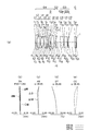
- FIG. 1A is a lens cross-sectional view of the single focus optical system according to the first embodiment.
- FIGS. 1B, 1 ⁇ / b> C, 1 ⁇ / b> D, and 1 ⁇ / b> E are aberration diagrams of the single focus optical system according to Example 1.
- FIGS. 1B, 1 ⁇ / b> C, 1 ⁇ / b> D, and 1 ⁇ / b> E are aberration diagrams of the single focus optical system according to Example 1.
- FIGS. 1A is a lens cross-sectional view of the single focus optical system according to the first embodiment.
- FIGS. 1B, 1 ⁇ / b> C, 1 ⁇ / b> D, and 1 ⁇ / b> E are aberration diagrams of the single focus optical system according to Example 1.
- FIGS. 1A is a lens cross-sectional view of the single focus optical system according to the first embodiment.
- the single focus optical system according to Example 1 includes a first lens group G1 having a positive refractive power and a second lens group G2 having a negative refractive power in order from the object side. And a third lens group G3 having a positive refractive power.
- the first lens group G1 includes an aperture stop S.
- the first lens group G1 includes a first sub group, a second sub group, and a third sub group.
- the first subgroup includes a negative meniscus lens L1 having a convex surface facing the object side.
- the second subgroup includes a biconvex positive lens L2, a biconcave negative lens L3, a biconcave negative lens L4, and a biconvex positive lens L5.
- the third subgroup includes a positive meniscus lens L6 having a convex surface facing the image side, a biconvex positive lens L7, a biconvex positive lens L8, and a biconvex positive lens L2 and a biconcave negative lens L3.
- the biconcave negative lens L4 and the biconvex positive lens L5 are cemented.
- the second lens group G2 includes a negative meniscus lens L9 having a convex surface directed toward the object side.
- the third lens group G3 includes a front side subgroup G3a and a rear side subgroup G3b.
- the front subgroup G3a is composed of a negative meniscus lens L9 having a convex surface directed toward the object side.
- the rear subgroup G3b includes a biconvex positive lens L10, a biconvex positive lens L11, and a negative meniscus lens L12 having a convex surface facing the object side.
- the negative meniscus lens L9 moves to the image side along the optical axis when focusing from an object at infinity to an object at a short distance.
- the aspheric surfaces are provided on a total of five surfaces including the object side surface of the negative meniscus lens L1, the image side surface of the biconcave negative lens L3, both surfaces of the negative meniscus lens L9, and the image side surface of the biconvex positive lens L10. .
- FIG. 2A is a lens cross-sectional view of the single focus optical system according to the second embodiment.
- 2B, 2C, 2D, and 2E are aberration diagrams of the single focus optical system according to Example 2.
- FIG. 2A is a lens cross-sectional view of the single focus optical system according to the second embodiment.
- 2B, 2C, 2D, and 2E are aberration diagrams of the single focus optical system according to Example 2.
- FIG. 2A is a lens cross-sectional view of the single focus optical system according to the second embodiment.
- 2B, 2C, 2D, and 2E are aberration diagrams of the single focus optical system according to Example 2.
- FIG. 2A is a lens cross-sectional view of the single focus optical system according to the second embodiment.
- 2B, 2C, 2D, and 2E are aberration diagrams of the single focus optical system according to Example 2.
- the single focus optical system according to Example 2 includes a first lens group G1 having a positive refractive power and a second lens group G2 having a negative refractive power in order from the object side. And a third lens group G3 having a positive refractive power.
- the first lens group G1 includes an aperture stop S.
- the first lens group G1 includes a first sub group, a second sub group, and a third sub group.
- the first subgroup includes a negative meniscus lens L1 having a convex surface facing the object side.
- the second subgroup includes a biconvex positive lens L2, a biconcave negative lens L3, a biconcave negative lens L4, and a biconvex positive lens L5.
- the third subgroup includes a biconvex positive lens L6, a biconvex positive lens L7, and a positive meniscus lens L8 having a convex surface facing the object side.
- the biconvex positive lens L2 and the biconcave negative lens L3 are cemented.
- the biconcave negative lens L4 and the biconvex positive lens L5 are cemented.
- the second lens group G2 includes a negative meniscus lens L9 having a convex surface directed toward the object side.
- the third lens group G3 includes a front side subgroup G3a and a rear side subgroup G3b.
- the front subgroup G3a includes a biconvex positive lens L10.
- the rear subgroup G3b includes a biconvex positive lens L11 and a negative meniscus lens L12 having a convex surface directed to the image side.
- the negative meniscus lens L9 moves to the image side along the optical axis when focusing from an object at infinity to an object at a short distance.
- the aspherical surface is provided on a total of four surfaces including both surfaces of the negative meniscus lens L1 and both surfaces of the negative meniscus lens L9.
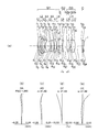
- FIG. 3A is a lens cross-sectional view of the single focus optical system according to Example 3.
- FIG. 3S. 3B, 3C, 3D, and 3E are aberration diagrams of the single focus optical system according to Example 3.
- FIGS. 3B, 3C, 3D, and 3E are aberration diagrams of the single focus optical system according to Example 3.
- the single focus optical system according to Example 3 includes, in order from the object side, a first lens group G1 having a positive refractive power and a second lens group G2 having a negative refractive power. And a third lens group G3 having a positive refractive power.
- the first lens group G1 includes an aperture stop S.
- the first lens group G1 includes a first sub group, a second sub group, and a third sub group.
- the first subgroup includes a negative meniscus lens L1 having a convex surface facing the object side.
- the second subgroup includes a negative meniscus lens L2 having a convex surface facing the object side, a biconvex positive lens L3, a biconcave negative lens L4, a biconcave negative lens L5, and a biconvex positive lens L6.
- the third subgroup includes a positive meniscus lens L7 having a convex surface facing the image side, a biconvex positive lens L8, and a positive meniscus lens L9 having a convex surface facing the object side.
- the negative meniscus lens L2, the biconvex positive lens L3, and the biconcave negative lens L4 are cemented.
- the biconcave negative lens L5 and the biconvex positive lens L6 are cemented.
- the second lens group G2 includes a negative meniscus lens L10 having a convex surface directed toward the object side.
- the third lens group G3 includes a front side subgroup G3a and a rear side subgroup G3b.
- the front subgroup G3a includes a biconvex positive lens L11.
- the rear subgroup G3b includes a biconvex positive lens L12, a biconvex positive lens L13, and a negative meniscus lens L14 having a convex surface facing the image side.
- the negative meniscus lens L10 moves to the image side along the optical axis when focusing from an infinitely distant object to a close object.
- the aspheric surfaces are provided on a total of three surfaces including the object side surface of the negative meniscus lens L2 and both surfaces of the negative meniscus lens L10.
- FIG. 4A is a lens cross-sectional view of the single focus optical system according to Example 4.
- FIG. FIGS. 4B, 4C, 4D, and 4E are aberration diagrams of the single focus optical system according to Example 4.
- FIGS. 4B, 4C, 4D, and 4E are aberration diagrams of the single focus optical system according to Example 4.
- the single focus optical system according to Example 4 includes, in order from the object side, a first lens group G1 having a positive refractive power and a second lens group G2 having a negative refractive power. And a third lens group G3 having a positive refractive power.
- the first lens group G1 includes an aperture stop S.
- the first lens group G1 includes a first sub group, a second sub group, and a third sub group.
- the first subgroup includes a negative meniscus lens L1 having a convex surface facing the object side and a negative meniscus lens L2 having a convex surface facing the object side.
- the second subgroup includes a biconvex positive lens L3, a biconcave negative lens L4, a biconcave negative lens L5, and a biconvex positive lens L6.
- the third subgroup includes a biconvex positive lens L7 and a positive meniscus lens L8 having a convex surface facing the object side.
- the biconvex positive lens L3 and the biconcave negative lens L4 are cemented.
- the biconcave negative lens L5 and the biconvex positive lens L6 are cemented.
- the second lens group G2 includes a negative meniscus lens L9 having a convex surface directed toward the object side.
- the third lens group G3 includes a front side subgroup G3a and a rear side subgroup G3b.
- the front subgroup G3a includes a biconvex positive lens L10.
- the rear subgroup G3b includes a biconvex positive lens L11, a biconcave negative lens L12, and a positive meniscus lens L13 having a convex surface facing the object side.
- the biconvex positive lens L11 and the biconcave negative lens L12 are cemented.
- the negative meniscus lens L9 moves to the image side along the optical axis when focusing from an object at infinity to an object at a short distance.
- the aspheric surfaces are provided on a total of four surfaces including both surfaces of the negative meniscus lens L2 and both surfaces of the negative meniscus lens L9.
- FIG. 5A is a lens cross-sectional view of the single focus optical system according to Example 5.
- FIG. 5B, 5C, 5D, and 5E are aberration diagrams of the single focus optical system according to Example 5.
- FIGS. 5A, 5B, 5C, 5D, and 5E are aberration diagrams of the single focus optical system according to Example 5.
- the single focus optical system according to Example 5 includes a first lens group G1 having a positive refractive power and a second lens group G2 having a negative refractive power in order from the object side. And a third lens group G3 having a positive refractive power.
- the first lens group G1 includes an aperture stop S.
- the first lens group G1 includes a first sub group, a second sub group, and a third sub group.
- the first subgroup includes a negative meniscus lens L1 having a convex surface facing the object side and a negative meniscus lens L2 having a convex surface facing the object side.
- the second subgroup includes a biconvex positive lens L3, a biconcave negative lens L4, a biconcave negative lens L5, and a biconvex positive lens L6.
- the third subgroup includes a biconvex positive lens L7 and a positive meniscus lens L8 having a convex surface facing the object side.
- the biconvex positive lens L3 and the biconcave negative lens L4 are cemented.
- the biconcave negative lens L5 and the biconvex positive lens L6 are cemented.
- the second lens group G2 includes a negative meniscus lens L9 having a convex surface directed toward the object side.
- the third lens group G3 includes a front side subgroup G3a and a rear side subgroup G3b.
- the front subgroup G3a includes a biconvex positive lens L10.
- the rear subgroup G3b includes a biconvex positive lens L11, a biconcave negative lens L12, and a positive meniscus lens L13 having a convex surface facing the object side.
- the biconvex positive lens L11 and the biconcave negative lens L12 are cemented.
- the negative meniscus lens L9 moves to the image side along the optical axis when focusing from an object at infinity to an object at a short distance.
- the aspheric surfaces are provided on a total of four surfaces including both surfaces of the negative meniscus lens L2 and both surfaces of the negative meniscus lens L9.
- FIG. 6A is a lens cross-sectional view of the single focus optical system according to Example 6.
- FIGS. 6B, 6C, 6D, and 6E are aberration diagrams of the single focus optical system according to Example 6.
- FIGS. 6B, 6C, 6D, and 6E are aberration diagrams of the single focus optical system according to Example 6.
- the single focus optical system according to Example 6 includes, in order from the object side, a first lens group G1 having a positive refractive power and a second lens group G2 having a negative refractive power. And a third lens group G3 having a positive refractive power.
- the first lens group G1 includes an aperture stop S.
- the first lens group G1 includes a first sub group, a second sub group, and a third sub group.
- the first subgroup includes a negative meniscus lens L1 having a convex surface facing the object side and a negative meniscus lens L2 having a convex surface facing the object side.
- the second subgroup includes a biconvex positive lens L3, a biconcave negative lens L4, a biconcave negative lens L5, and a biconvex positive lens L6.
- the third subgroup includes a biconvex positive lens L7 and a biconvex positive lens L8.
- the biconvex positive lens L3 and the biconcave negative lens L4 are cemented.
- the biconcave negative lens L5 and the biconvex positive lens L6 are cemented.
- the second lens group G2 includes a negative meniscus lens L9 having a convex surface directed toward the object side.
- the third lens group G3 includes a front side subgroup G3a and a rear side subgroup G3b.
- the front subgroup G3a includes a biconvex positive lens L10.
- the rear subgroup G3b includes a biconvex positive lens L11, a biconcave negative lens L12, and a positive meniscus lens L13 having a convex surface facing the object side.
- the biconvex positive lens L11 and the biconcave negative lens L12 are cemented.
- the negative meniscus lens L9 moves to the image side along the optical axis when focusing from an object at infinity to an object at a short distance.
- the aspheric surfaces are provided on a total of four surfaces including both surfaces of the negative meniscus lens L2 and both surfaces of the negative meniscus lens L9.
- FIG. 7A is a lens cross-sectional view of the single focus optical system according to Example 7.
- FIGS. 7B, 7C, 7D, and 7E are aberration diagrams of the single focus optical system according to Example 7.
- FIGS. 7B, 7C, 7D, and 7E are aberration diagrams of the single focus optical system according to Example 7.
- the single focus optical system according to Example 7 includes, in order from the object side, a first lens group G1 having a positive refractive power and a second lens group G2 having a negative refractive power. And a third lens group G3 having a positive refractive power.
- the first lens group G1 includes an aperture stop S.
- the first lens group G1 includes a first sub group, a second sub group, and a third sub group.
- the first subgroup includes a negative meniscus lens L1 having a convex surface facing the object side and a positive meniscus lens L2 having a convex surface facing the object side.
- the second subgroup includes a positive meniscus lens L3 having a convex surface facing the object side, a negative meniscus lens L4 having a convex surface facing the object side, a biconcave negative lens L5, and a biconvex positive lens L6.
- the third subgroup includes a biconvex positive lens L7 and a positive meniscus lens L8 having a convex surface facing the object side.
- the positive meniscus lens L3 and the negative meniscus lens L4 are cemented.
- the biconcave negative lens L5 and the biconvex positive lens L6 are cemented.
- the second lens group G2 includes a negative meniscus lens L9 having a convex surface directed toward the object side.
- the third lens group G3 includes a front side subgroup G3a and a rear side subgroup G3b.
- the front subgroup G3a is composed of a positive meniscus lens L10 having a convex surface facing the image side.
- the rear subgroup G3b includes a biconvex positive lens L11, a biconcave negative lens L12, and a biconvex positive lens L13.
- the biconvex positive lens L11 and the biconcave negative lens L12 are cemented.
- the negative meniscus lens L9 moves to the image side along the optical axis when focusing from an object at infinity to an object at a short distance.
- the aspheric surfaces are provided on both sides of the negative meniscus lens L9.
- FIG. 8A is a lens cross-sectional view of the single focus optical system according to Example 8.
- FIGS. 8B, 8C, 8D, and 8E are aberration diagrams of the single focus optical system according to Example 8.
- FIGS. 8B, 8C, 8D, and 8E are aberration diagrams of the single focus optical system according to Example 8.
- the single focus optical system according to Example 8 has a first lens group G1 having a positive refractive power and a second lens group G2 having a negative refractive power in order from the object side. And a third lens group G3 having a positive refractive power.
- the first lens group G1 includes an aperture stop S.
- the first lens group G1 includes a first sub group, a second sub group, and a third sub group.
- the first subgroup includes a negative meniscus lens L1 having a convex surface facing the object side and a negative meniscus lens L2 having a convex surface facing the object side.
- the second subgroup includes a biconvex positive lens L3, a biconcave negative lens L4, a biconcave negative lens L5, and a biconvex positive lens L6.
- the third subgroup includes a biconvex positive lens L7 and a biconvex positive lens L8.
- the biconvex positive lens L3 and the biconcave negative lens L4 are cemented.
- the biconcave negative lens L5 and the biconvex positive lens L6 are cemented.
- the second lens group G2 includes a negative meniscus lens L9 having a convex surface directed toward the object side.
- the third lens group G3 includes a front side subgroup G3a and a rear side subgroup G3b.
- the front subgroup G3a includes a biconvex positive lens L10.
- the rear subgroup G3b includes a biconcave negative lens L11 and a biconvex positive lens L12.
- the biconcave negative lens L11 and the biconvex positive lens L12 are cemented.
- the negative meniscus lens L9 moves to the image side along the optical axis
- the biconvex positive lens L10 moves to the object side along the optical axis.
- the aspheric surfaces are provided on a total of six surfaces including both surfaces of the negative meniscus lens L2, both surfaces of the negative meniscus lens L9, and both surfaces of the biconvex positive lens L10.
- FIG. 9A is a lens cross-sectional view of the single focus optical system according to Example 9.
- FIGS. 9B, 9 ⁇ / b> C, 9 ⁇ / b> D, and 9 ⁇ / b> E are aberration diagrams of the single focus optical system according to Example 9.
- FIGS. 9B, 9 ⁇ / b> C, 9 ⁇ / b> D, and 9 ⁇ / b> E are aberration diagrams of the single focus optical system according to Example 9.
- FIGS. 9A is a lens cross-sectional view of the single focus optical system according to Example 9.
- FIGS. 9B, 9 ⁇ / b> C, 9 ⁇ / b> D, and 9 ⁇ / b> E are aberration diagrams of the single focus optical system according to Example 9.
- FIGS. 9B, 9 ⁇ / b> C, 9 ⁇ / b> D, and 9 ⁇ / b> E are aberration diagrams of the single focus optical system according to Example 9.
- the single focus optical system according to Example 9 includes a first lens group G1 having a positive refractive power and a second lens group G2 having a negative refractive power in order from the object side. And a third lens group G3 having a positive refractive power.
- the first lens group G1 includes an aperture stop S.
- the first lens group G1 includes a first sub group, a second sub group, and a third sub group.
- the first subgroup includes a negative meniscus lens L1 having a convex surface facing the object side and a negative meniscus lens L2 having a convex surface facing the object side.
- the second subgroup includes a biconvex positive lens L3, a biconcave negative lens L4, a biconcave negative lens L5, and a biconvex positive lens L6.
- the third subgroup includes a biconvex positive lens L7 and a positive meniscus lens L8 having a convex surface facing the object side.
- the biconvex positive lens L3 and the biconcave negative lens L4 are cemented.
- the biconcave negative lens L5 and the biconvex positive lens L6 are cemented.
- the second lens group G2 includes a negative meniscus lens L9 having a convex surface directed toward the object side.
- the third lens group G3 includes a front side subgroup G3a and a rear side subgroup G3b.
- the front subgroup G3a includes a biconvex positive lens L10.
- the rear subgroup G3b includes a negative meniscus lens L11 having a convex surface directed toward the object side, and a biconvex positive lens L12.
- the negative meniscus lens L11 and the biconvex positive lens L12 are cemented.
- the negative meniscus lens L9 moves to the image side along the optical axis
- the biconvex positive lens L10 moves to the object side along the optical axis.
- the aspheric surfaces are provided on a total of four surfaces including both surfaces of the negative meniscus lens L9 and both surfaces of the biconvex positive lens L10.
- FIG. 10A is a lens cross-sectional view of the single focus optical system according to Example 10.
- FIG. FIGS. 10B, 10C, 10D, and 10E are aberration diagrams of the single focus optical system according to Example 10.
- FIGS. 10A the single focus optical system according to Example 10 includes, in order from the object side, a first lens group G1 having a positive refractive power and a second lens group G2 having a negative refractive power. And a third lens group G3 having a positive refractive power.
- the first lens group G1 includes an aperture stop S.
- the first lens group G1 includes a first sub group, a second sub group, and a third sub group.
- the first subgroup includes a negative meniscus lens L1 having a convex surface facing the object side and a positive meniscus lens L2 having a convex surface facing the object side.
- the second subgroup includes a positive meniscus lens L3 having a convex surface facing the object side, a negative meniscus lens L4 having a convex surface facing the object side, a biconcave negative lens L5, and a biconvex positive lens L6.
- the third subgroup includes a positive meniscus lens L7 having a convex surface facing the image side, and a biconvex positive lens L8.
- the positive meniscus lens L3 and the negative meniscus lens L4 are cemented.
- the biconcave negative lens L5 and the biconvex positive lens L6 are cemented.
- the second lens group G2 includes a negative meniscus lens L9 having a convex surface directed toward the object side.
- the third lens group G3 includes a front side subgroup G3a and a rear side subgroup G3b.
- the front subgroup G3a includes a biconvex positive lens L10.
- the rear subgroup G3b includes a biconcave negative lens L11 and a biconvex positive lens L12.
- the biconcave negative lens L11 and the biconvex positive lens L12 are cemented.
- the negative meniscus lens L9 moves to the image side along the optical axis
- the biconvex positive lens L10 moves to the object side along the optical axis.
- the aspheric surfaces are provided on a total of four surfaces including both surfaces of the negative meniscus lens L9 and both surfaces of the biconvex positive lens L10.
- FIG. 11A is a lens cross-sectional view of the single focus optical system according to Example 11.
- FIGS. 11B, 11 ⁇ / b> C, 11 ⁇ / b> D, and 11 ⁇ / b> E are aberration diagrams of the single focus optical system according to Example 11.
- FIGS. 11B, 11 ⁇ / b> C, 11 ⁇ / b> D, and 11 ⁇ / b> E are aberration diagrams of the single focus optical system according to Example 11.
- FIGS. 11A is a lens cross-sectional view of the single focus optical system according to Example 11.
- FIGS. 11B, 11 ⁇ / b> C, 11 ⁇ / b> D, and 11 ⁇ / b> E are aberration diagrams of the single focus optical system according to Example 11.
- FIGS. 11A is a lens cross-sectional view of the single focus optical system according to Example 11.
- the single focus optical system according to Example 11 includes a first lens group G1 having a positive refractive power and a second lens group G2 having a negative refractive power in order from the object side. And a third lens group G3 having a positive refractive power.
- the first lens group G1 includes an aperture stop S.
- the first lens group G1 includes a first sub group, a second sub group, and a third sub group.
- the first subgroup includes a negative meniscus lens L1 having a convex surface facing the object side and a negative meniscus lens L2 having a convex surface facing the object side.
- the second subgroup includes a biconvex positive lens L3, a biconcave negative lens L4, a biconcave negative lens L5, and a biconvex positive lens L6.
- the third subgroup includes a biconvex positive lens L7, a biconvex positive lens L8, and a negative meniscus lens L9 having a convex surface facing the image side.
- the biconvex positive lens L3 and the biconcave negative lens L4 are cemented.
- the biconcave negative lens L5 and the biconvex positive lens L6 are cemented.
- the biconvex positive lens L8 and the negative meniscus lens L9 are cemented.
- the second lens group G2 includes a negative meniscus lens L10 having a convex surface directed toward the object side.
- the third lens group G3 includes a front side subgroup G3a and a rear side subgroup G3b.
- the front subgroup G3a includes a negative meniscus lens L11 having a convex surface directed toward the object side, and a biconvex positive lens L12.
- the rear subgroup G3b includes a negative meniscus lens L13 having a convex surface facing the image side.
- the negative meniscus lens L11 and the biconvex positive lens L12 are cemented.
- the negative meniscus lens L10 moves to the image side along the optical axis, and the negative meniscus lens L11 and the biconvex positive lens L12 move along the optical axis. Move to the side.
- the aspheric surfaces are provided on a total of five surfaces including both surfaces of the negative meniscus lens L2, both surfaces of the negative meniscus lens L10, and the image side surface of the biconvex positive lens L12.
- FIG. 12A is a lens cross-sectional view of the single focus optical system according to Example 12.
- FIG. 12B, 12C, 12D, and 12E are aberration diagrams of the single focus optical system according to Example 12.
- FIGS. 12A, 12B, 12C, 12D, and 12E are aberration diagrams of the single focus optical system according to Example 12.
- the first lens group G1 includes an aperture stop S.
- the first lens group G1 includes a first sub group, a second sub group, and a third sub group.
- the first subgroup includes a negative meniscus lens L1 having a convex surface facing the object side and a negative meniscus lens L2 having a convex surface facing the object side.
- the second subgroup includes a biconvex positive lens L3, a biconcave negative lens L4, a biconcave negative lens L5, and a biconvex positive lens L6.
- the third subgroup includes a biconvex positive lens L7, a biconvex positive lens L8, and a negative meniscus lens L9 having a convex surface facing the image side.
- the biconvex positive lens L3 and the biconcave negative lens L4 are cemented.
- the biconcave negative lens L5 and the biconvex positive lens L6 are cemented.
- the biconvex positive lens L8 and the negative meniscus lens L9 are cemented.
- the second lens group G2 includes a biconcave negative lens L10 and a negative meniscus lens L11 having a convex surface directed toward the object side.
- the biconcave negative lens L10 and the negative meniscus lens L11 are cemented.
- the third lens group G3 includes a front side subgroup G3a and a rear side subgroup G3b.
- the front subgroup G3a is composed of a biconvex positive lens L12.
- the rear subgroup G3b includes a biconcave negative lens L13.
- the biconcave negative lens L10 and the negative meniscus lens L11 move to the image side along the optical axis, and the biconvex positive lens L12 follows the optical axis. Move to the object side.
- the aspheric surfaces are provided on a total of six surfaces including both surfaces of the negative meniscus lens L2, the object side surface of the biconcave negative lens L10, the image side surface of the negative meniscus lens L11, and both surfaces of the biconvex positive lens L12.
- r1, r2,... are the curvature radii of the lens surfaces, d1, d2,... Are the thickness or air spacing of each lens, and nd1, nd2,. , ⁇ d1, ⁇ d2,... Are Abbe numbers of the respective lenses, and * is an aspherical surface.
- f is the focal length of the entire single-focus optical system, FNO. Is the F number, ⁇ is the half angle of view, IH is the image height, FB is the back focus, f1, f2,... Are the focal lengths of the lens groups.
- the total length is obtained by adding back focus to the distance from the lens front surface to the lens final surface.
- the back focus represents the distance from the last lens surface to the paraxial image surface in terms of air.
- the unit of angle is ° (degrees).
- infinity represents when an object at infinity is in focus
- short distance represents when an object at near distance is in focus.
- the value at the short distance is the distance from the object to the image.
- the aspherical shape is expressed by the following equation when the optical axis direction is z, the direction orthogonal to the optical axis is y, the conical coefficient is k, and the aspherical coefficients are A4, A6, A8, and A10. .
- z (y 2 / r) / [1+ ⁇ 1 ⁇ (1 + k) (y / r) 2 ⁇ 1/2 ] + A4y 4 + A6y 6 + A8y 8 + A10y 10
- “en” (n is an integer) represents “10 ⁇ n ”.
- the symbols of these specification values are common to the numerical data of the examples described later.
- Examples of the optical device according to the present embodiment include an imaging device and a projection device. Hereinafter, specific examples of the imaging device and the projection device will be described.
- FIG. 13 is a cross-sectional view of a single-lens mirrorless camera as an imaging device.
- a photographing optical system 2 is arranged in a lens barrel of the single lens mirrorless camera 1.
- the mount unit 3 allows the photographing optical system 2 to be attached to and detached from the body of the single lens mirrorless camera 1.
- a screw type mount, a bayonet type mount, or the like is used as the mount unit 3.
- a bayonet type mount is used.
- An imaging element surface 4 and a back monitor 5 are disposed on the body of the single lens mirrorless camera 1.
- a small CCD or CMOS is used as the image sensor.
- the photographing optical system 2 of the single-lens mirrorless camera for example, the single focus optical system shown in the first to twelfth embodiments is used.
- FIG. 14 and 15 are conceptual diagrams of the configuration of the imaging apparatus.
- FIG. 14 is a front perspective view showing the appearance of a single-lens mirrorless camera 40 as an imaging device
- FIG. 15 is a rear perspective view of the same.
- the photographing optical system 41 of the single lens mirrorless camera 40 the single focus optical system shown in the first to twelfth embodiments is used.
- the single-lens mirrorless camera 40 includes a photographing optical system 41 located on the photographing optical path 42, a shutter button 45, a liquid crystal display monitor 47, and the like, and a shutter button 45 disposed above the single-lens mirrorless camera 40.
- photographing optical system 41 for example, the single focus optical system of the first embodiment in conjunction therewith.
- An object image formed by the photographing optical system 41 is formed on an image sensor (photoelectric conversion surface) provided in the vicinity of the imaging surface.
- the object image received by the image sensor is displayed on the liquid crystal display monitor 47 provided on the back of the camera as an electronic image by the processing means.
- the taken electronic image can be recorded in the storage means.
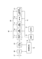
- FIG. 16 is a block diagram showing an internal circuit of a main part of the single-lens mirrorless camera 40.
- the processing means described above is configured by, for example, the CDS / ADC unit 24, the temporary storage memory 17, the image processing unit 18, and the like, and the storage unit is configured by the storage medium unit 19 or the like.
- the single lens mirrorless camera 40 is connected via the buses 14 and 15 to the operation unit 12, the control unit 13 connected to the operation unit 12, and the control signal output port of the control unit 13.
- the image pickup drive circuit 16 the temporary storage memory 17, the image processing unit 18, the storage medium unit 19, the display unit 20, and the setting information storage memory unit 21 are provided.
- the temporary storage memory 17, the image processing unit 18, the storage medium unit 19, the display unit 20, and the setting information storage memory unit 21 can input and output data with each other via the bus 22.
- a CCD 49 and a CDS / ADC unit 24 are connected to the imaging drive circuit 16.
- the operation unit 12 includes various input buttons and switches, and notifies the control unit 13 of event information input from the outside (camera user) via these buttons.
- the control unit 13 is a central processing unit composed of, for example, a CPU and has a built-in program memory (not shown) and controls the entire single-lens mirrorless camera 40 according to a program stored in the program memory.
- the CCD 49 is an image pickup element that is driven and controlled by the image pickup drive circuit 16, converts the light amount of each pixel of the object image formed via the photographing optical system 41 into an electric signal, and outputs the electric signal to the CDS / ADC unit 24.
- the CDS / ADC unit 24 amplifies the electrical signal input from the CCD 49 and performs analog / digital conversion, and raw video data (Bayer data, hereinafter referred to as RAW data) obtained by performing the amplification and digital conversion. Is output to the temporary storage memory 17.
- the temporary storage memory 17 is a buffer made of, for example, SDRAM, and is a memory device that temporarily stores RAW data output from the CDS / ADC unit 24.
- the image processing unit 18 reads out the RAW data stored in the temporary storage memory 17 or the RAW data stored in the storage medium unit 19, and includes distortion correction based on the image quality parameter designated by the control unit 13. It is a circuit that performs various image processing electrically.
- the storage medium unit 19 is detachably mounted with a card-type or stick-type recording medium made of, for example, a flash memory, and the RAW data transferred from the temporary storage memory 17 or the image processing unit 18 to these flash memories. Image-processed image data is recorded and held.
- the display unit 20 includes a liquid crystal display monitor 47 and the like, and displays captured RAW data, image data, an operation menu, and the like.
- the setting information storage memory unit 21 includes a ROM unit that stores various image quality parameters in advance, and a RAM unit that stores image quality parameters read from the ROM unit by an input operation of the operation unit 12.
- the single focus optical system of the present invention can also be used in an image pickup apparatus having a quick return mirror.
- FIG. 17 is a cross-sectional view of a projector as a projection apparatus.
- the projector 100 includes a light source unit 110, an illumination unit 120, an image forming unit 130, and a projection unit 140.
- the light source unit 110 includes a light source 111 and a reflecting member 112. Illumination light is emitted from the light source 111.
- the illumination light is white light.
- the illumination light is reflected by the reflecting member 112 and enters the illumination unit 120.
- the illumination unit 120 includes a first dichroic mirror 121, a second dichroic mirror 122, a third dichroic mirror 123, a first reflecting member 124, and a second reflecting member 125.
- the first dichroic mirror 121 transmits light in the red wavelength range (hereinafter referred to as “red light”) and reflects light in other wavelength ranges.
- the second dichroic mirror 122 reflects light in the green wavelength range (hereinafter referred to as “green light”) and transmits light in other wavelength ranges.
- the third dichroic mirror 123 reflects light in the blue wavelength range (hereinafter referred to as “blue light”) and transmits light in other wavelength ranges. Red light, green light, and blue light are incident on the image forming unit 130. Instead of the third dichroic mirror 123, a normal plane reflecting mirror may be used.
- the image forming unit 130 includes a first display element 131, a second display element 132, and a third display element 133.
- the first display element 131 is irradiated with red light through the first reflecting member 124.
- the second display element 132 is irradiated with green light.
- the third display element 133 is irradiated with blue light through the second reflecting member 125.
- the same image is displayed on the first display element 131, the second display element 132, and the third display element 133. Therefore, a red image is displayed on the first display element 131, a green image is displayed on the second display element 132, and a blue image is displayed on the third display element 133.
- the light emitted from the first display element 131, the second display element 132, and the third display element 133 is incident on the projection unit 140.
- the projection unit 140 includes a dichroic prism 141 and a projection optical system 142.
- the light emitted from the first display element 131, the second display element 132, and the third display element 133 is synthesized by the dichroic prism 141.
- the image forming unit 130 displays a red image, a green image, and a blue image. Three images are synthesized by the dichroic prism 141.
- Projection optical system 142 projects the combined three images at a predetermined position.
- this projection optical system 142 for example, the single focus optical system shown in the first to twelfth embodiments is used.
- the image forming unit 130 may be a light valve such as a DMD (digital mirror device).
- the light from the light source unit 110 may be reflected by the light valve, and the image from the light valve may be enlarged and projected by the projection unit 140.
- the projector 100 configured as described above, by adopting the single focus optical system of the present invention as the projection optical system 142, it is possible to project an image with low noise and high resolution over a wide projection range.
- the single focus optical system according to the present invention is suitable for a single focus optical system in which various aberrations are well corrected while having a wide angle of view and a small F number.
- the optical device according to the present invention is suitable for an imaging device that captures a wide imaging range with low noise and high resolution, and a projection device that projects an image with low noise and high resolution over a wide projection range.
Abstract
単焦点光学系は、正の屈折力を有する第1レンズ群G1と、負の屈折力を有する第2レンズ群G2と、正の屈折力を有する第3レンズ群G3と、から構成され、第1レンズ群G1は、第1副群、第2副群及び第3副群を少なくとも有し、第1副群は、負レンズ成分を有し、第2副群は、2つのメニスカスレンズ成分からなり、第3副群は、複数の正レンズ成分からなり、第3レンズ群G3は、前側副群G3aと後側副群G3bとからなり、前側副群G3aは、正レンズ成分のみからなり、フォーカス時、第1レンズ群G1は固定で、第2レンズ群G2は移動可能で、後側副群G3bは固定であり、第1レンズ群G1と第2レンズ群G2との間隔、及び第2レンズ群G2と前側副群G3aとの間隔は少なくとも可変で、且つ、第1レンズ群G1内、第2レンズ群G2内、前側副群G3a内、後側副群G3b内の各レンズ面間隔は一定である。
Description
本発明は、単焦点光学系及びそれを備えた光学装置に関する。
口径比が大きく、且つ画角が広い光学系では、フォーカス時の収差変動が、高い結像性能の確保にとって大きな問題となる。特に、大口径比であるほど、わずかな収差変動が著しい結像性能の劣化を招く。また、画角が広くなるほど、その傾向が強い。
口径比が大きい結像光学系におけるフォーカスの例として、望遠レンズにおけるフォーカスがある。例えば、従来の望遠レンズとして、物体から順に、正の屈折力を有する第1レンズ群、負の屈折力を有する第2レンズ群及び正の屈折力を有する第3レンズ群にて構成された望遠レンズがある。この望遠レンズにおけるフォーカスでは、第2レンズ群が移動する。これにより、無限遠から相当な至近距離に亘って、収差変動を小さく収めることができる。ただし、従来の望遠レンズでは画角が15度未満であるため、撮影範囲の中心から周辺部に亘り結像性能を良好に維持できているにすぎない。
高い結像性能を有する結像光学系のタイプとして、ガウスタイプが知られている。ガウスタイプの光学系は、物体側から順に、正の屈折力を有する物体側群と、正の屈折力を有する像側群と、より構成されている。
物体側群は、2枚乃至3枚の正レンズと、1枚の負レンズとからなる。この負レンズは、直前の正レンズと接合されている場合がある。また、像側群は、1枚の負レンズと、2枚乃至3枚の正レンズと、からなる。この負レンズも、直後の正レンズと接合されている場合がある。
また、ガウスタイプの光学系は、その中央部を境に物体側の形状と像側の形状がおおむね対称で、且つコンセントリックな形状になっている。コンセントリックな形状では、各レンズで、2つのレンズ面における曲率中心が中央部の近くに位置している。
これにより、ガウスタイプの光学系では、大口径比であっても、各収差がある程度良好に補正できている。しかし、従来以上の結像性能を実現しようとすると、ガウスタイプの光学系では画角50度弱が限界である。よって、ガウスタイプの光学系で、50度以上の画角の実現は困難である。
これらの問題を解決した広角撮影レンズが、各種提案されている。提案されている広角撮影レンズでは、Fナンバーが1.4程度になっている。画角が広くFナンバーが小さい広角撮影レンズの光学系として、特許文献1~6に開示された光学系がある。
特許文献1や特許文献2の光学系ではFナンバーが1.24であるため、Fナンバーが小さい光学系が実現できている。しかしながら、画角が63.6°であるため、特許文献1や特許文献2の光学系では、画角が十分に広い光学系が実現できていない。
また、特許文献3、特許文献4、特許文献5及び特許文献6の光学系では、Fナンバーが1.4であるが、これ以上Fナンバーを小さくしようとするか、又は画角を広くしようとすると、上述した諸収差の補正がさらに困難となる。
本発明は、このような課題に鑑みてなされたものであって、広い画角と小さいFナンバーを有しながらも、諸収差が良好に補正された単焦点光学系及びそれを備えた光学装置を提供することを目的とする。
上述した課題を解決し、目的を達成するために、本発明の単焦点光学系は、
距離が長い方の拡大側の共役点と距離が短い方の縮小側の共役点との共役関係を形成する単焦点光学系であって、
単焦点光学系は、拡大側から順に、
正の屈折力を有する第1レンズ群と、
負の屈折力を有する第2レンズ群と、
正の屈折力を有する第3レンズ群と、から構成され、
レンズ成分は、単レンズ又は接合レンズであり、
第1レンズ群は、拡大側から順に、第1副群、第2副群及び第3副群を有するか、又は、第1副群、1つの正レンズ成分、第2副群及び第3副群を有し、
第1副群は、1つの負レンズ成分からなるか、又は、連続した複数の負レンズ成分からなり、
第2副群は、凹面どうしが向かい合った2つのメニスカスレンズ成分からなり、
第3副群は、複数の正レンズ成分からなり、且つ、第1レンズ群中にて、第2副群の縮小側に隣り合う正レンズ成分全てを含み、
第3レンズ群は、拡大側から順に、前側副群と、後側副群と、からなり、
前側副群は、正レンズ成分のみからなり、
フォーカス時、第1レンズ群は固定で、第2レンズ群は移動可能で、後側副群は固定であり、
第1レンズ群と第2レンズ群との間隔、及び第2レンズ群と前側副群との間隔は少なくとも可変で、且つ、
第1レンズ群内、第2レンズ群内、前側副群内、後側副群内の各レンズ面間隔は、一定であることを特徴とする。
また、本発明の光学装置は、
光学系と、縮小側に配置された撮像素子と、を有し、
撮像素子は撮像面を有し、且つ光学系によって撮像面上に形成された像を電気信号に変換し、
光学系が上述の単焦点光学系であることを特徴とする。
光学系と、縮小側に配置された撮像素子と、を有し、
撮像素子は撮像面を有し、且つ光学系によって撮像面上に形成された像を電気信号に変換し、
光学系が上述の単焦点光学系であることを特徴とする。
また、本発明の別の光学装置は、
光学系と、縮小側に配置された表示素子と、を有し、
表示素子は表示面を有し、
表示面上に表示された画像は、光学系によって拡大側に投影され、
光学系が上述の単焦点光学系であることを特徴とする。
光学系と、縮小側に配置された表示素子と、を有し、
表示素子は表示面を有し、
表示面上に表示された画像は、光学系によって拡大側に投影され、
光学系が上述の単焦点光学系であることを特徴とする。
本発明によれば、広い画角と小さいFナンバーを有しながらも、諸収差が良好に補正された単焦点光学系及びそれを備えた光学装置を提供することができる。
以下に、本発明に係る単焦点光学系及びそれを備えた光学装置の実施形態及び実施例を、図面に基づいて詳細に説明する。なお、この実施形態及び実施例によりこの発明が限定されるものではない。
本実施形態の単焦点光学系は、距離が長い方の拡大側の共役点と距離が短い方の縮小側の共役点との共役関係を形成する単焦点光学系であって、単焦点光学系は、拡大側から順に、正の屈折力を有する第1レンズ群と、負の屈折力を有する第2レンズ群と、正の屈折力を有する第3レンズ群と、から構成され、レンズ成分は、単レンズ又は接合レンズであり、第1レンズ群は、拡大側から順に、第1副群、第2副群及び第3副群を有するか、又は、第1副群、1つの正レンズ成分、第2副群及び第3副群を有し、第1副群は、1つの負レンズ成分からなるか、又は、連続した複数の負レンズ成分からなり、第2副群は、凹面どうしが向かい合った2つのメニスカスレンズ成分からなり、第3副群は、複数の正レンズ成分からなり、且つ、第1レンズ群中にて、第2副群の縮小側に隣り合う正レンズ成分全てを含み、第3レンズ群は、拡大側から順に、前側副群と、後側副群と、からなり、前側副群は、正レンズ成分のみからなり、フォーカス時、第1レンズ群は固定で、第2レンズ群は移動可能で、後側副群は固定であり、第1レンズ群と第2レンズ群との間隔、及び第2レンズ群と前側副群との間隔は少なくとも可変で、且つ、第1レンズ群内、第2レンズ群内、前側副群内、後側副群内の各レンズ面間隔は、一定であることを特徴とする。
本実施形態の単焦点光学系とガウスタイプの光学系とを比較しながら、本実施形態の単焦点光学系について説明する。以下の説明では、拡大側に物体側が対応し、縮小側に像側が対応する。
本実施形態の単焦点光学系は、口径比が大きい光学系である。よって、従来の望遠レンズにおけるフォーカスと同様に、光学系を、正の屈折力を有する第1レンズ群と、負の屈折力を有する第2レンズ群と、正の屈折力を有する第3レンズ群と、で構成し、フォーカス時に第2レンズ群を移動させている。
ただし、従来の望遠レンズに比べて、画角がはるかに広い。よって、本実施形態の単焦点光学系では、フォーカス方式は、従来の望遠レンズのフォーカス方式を採用しているが、光学系のレンズ構成は、従来の望遠レンズとは異なるレンズ構成を採用している。
上述のように、画角が広くなると、わずかな収差変動で結像性能が大きく劣化する。フォーカスによる収差変動を小さく収めるための基本的考え方は、合計収差量をできるだけ小さくすることである。ここでの合計収差量とは、正の屈折力を有する第1レンズ群で発生する収差量と正の屈折力を有する第3レンズ群で発生する収差量との合計である。特に、第1レンズ群で発生する収差量を小さく抑えることが肝要である。
上述のように、ガウスタイプの光学系は高い結像性能を有する。そのため、ガウスタイプの光学系を変形することで、口径比を更に大きくすると共に、画角を更に広くすることが可能である。そこで、本実施形態の単焦点光学系では、広い画角、例えば50度以上の画角においてもフォーカス時の収差変動を極力小さく収めるために、ガウスタイプの光学系をさらに広い画角に対応できるように変形し、変形した光学系を正の屈折力を有する第1レンズ群として用いている。
このように、本実施形態の単焦点光学系は、ガウスタイプの光学系をベースにしている。すなわち、ガウスタイプにおける基本的なレンズの配列やレンズの形状(以下、「基本配列」という)を極力維持しつつ、様々な工夫を加えている。よって、第1レンズ群は、ガウスタイプの物体側群や像側群と同様の基本配列を備えている。
ただし、第1レンズ群では、ガウスタイプの物体側群における基本配列や像側群における基本配列を極力維持しつつ、屈折力の配列のバランスをシフトさせて、ガウスタイプの屈折力配置とは異なる屈折力配置としている。
具体的には、第1レンズ群のうち、物体側群に相当する部分については、物体側群における正の屈折力を負側にシフトさせた状態にしている。また、第1レンズ群のうち、像側群に相当する部分については、像側群における正の屈折力を正側に大きくシフトした状態にしている。屈折力の負側へのシフトとは、正の屈折力を小さな負の屈折力に変更することや、正の屈折力をより小さな正の屈折力にすることである。屈折力の正側へのシフトとは、正の屈折力をより大きな正の屈折力にすることである。
このように、本実施形態の単焦点光学系では、ガウスタイプにおける基本配列を極力維持しながら、収差補正にとって有利になるように、光学系の構成を再構成している。すなわち、ガウスタイプの物体側群に相当する部分の屈折力を負側にシフトさせると共に、像側群に相当する部分の屈折力を正側に大きくシフトさせた状態となるように、ガウスタイプにおける基本配列を再構成している。
第1レンズ群は3つの副群を含んでいる。単焦点光学系全系の焦点距離が長いうちは、物体側群に相当する部分の屈折力をあまり負側に大きくシフトしない方が良い。このような事情を鑑み、その場合は第2副群の直前、すなわち、1または複数の負レンズ成分からなる第1副群と第2副群との間に1枚の正レンズ成分を配置してもよい。このようにすることで、球面収差や軸上色収差を良好に補正することができる。ただし、2枚以上の正レンズ成分を配置することは、光学系の全長が長くなり、また、物体側群に相当する部分の径が肥大化するので、かえって好ましくない。
一方、単焦点光学系全系の焦点距離を短くする場合には、第1副群と第2副群との間に正レンズ成分は配置しなくてもよい。このようにすることで、画角を広くすることができる。
第2副群は、凹面どうしが向かい合った2つのメニスカスレンズ成分からなる。一方のメニスカスレンズ成分は、縮小側に凹面を向けて配置され、他方のメニスカスレンズ成分は、拡大側に凹面を向けて配置されている。よって、本実施形態の単焦点光学系では、一方のメニスカスレンズ成分から拡大側の部分が物体側群に相当する部分になるので、この部分の屈折力が負側にシフトされている。また、他方のメニスカスレンズ成分から縮小側の部分が像側群に相当する部分になるので、この部分の屈折力が正側に大きくシフトしている。
また、第2レンズ群はフォーカスのために移動可能である。
また、第3レンズ群は基本的には固定である。ただし、フォーカス時に第2レンズ群が移動することで、収差変動が生じる。よって、収差の変動量に応じて、移動するレンズ群の数を増やしても良い。
第3レンズ群は、拡大側から順に、前側副群と後側副群とで構成されている。また、前側副群は正レンズ成分のみからなる。そこで、フォーカス時の収差変動の変動量が許容できないほど大きい場合には、フォーカス時に前側副群を第2レンズ群と共に、両者の間隔を変えつつ移動させても良い。
この場合、第1レンズ群と後側副群は固定である。また、第1レンズ群と第2レンズ群との間隔、第2レンズ群と前側副群との間隔及び前側副群と後側副群との間隔は、いずれも可変ということになる。また、第1レンズ群内、第2レンズ群内、前側副群内、後側副群内の各レンズ面間隔は一定である。
このように、本実施形態の単焦点光学系では、ガウスタイプの光学系に対して、物体側群に相当する部分における屈折力を負側へシフトすると共に、像側群に相当する部分における屈折力を正側へ大きくシフトした構成を採用している。そのため、屈折力の面では、本実施形態の単焦点光学系はガウスタイプの光学系とは異なる。
しかしながら、本実施形態の単焦点光学系も、ガウスタイプの基本配列を備えている。よって、本実施形態の単焦点光学系は、収差補正のポテンシャルが極めて高い光学系をベースにしているということができる。そのため、本実施形態の単焦点光学系では、特に、球面収差、コマ収差、軸上色収差及び倍率色収差を極めて良好に補正できる。その結果、従来のガウスタイプの光学系よりも高い結像性能を有する単焦点光学系を実現することができる。例えば、単焦点光学系において、1.4よりも小さいFナンバーと、50°以上の画角を確保することができる。
このように、本実施形態の単焦点光学系によれば、標準レンズから広角レンズのカテゴリーにおいて、1.4よりも小さいFナンバーを有し、かつ、収差補正のポテンシャルが極めて高い単焦点光学系を提供することができる。特に、結像性能においては、従来の35mmフィルムサイズ用の単焦点光学系を凌駕するレベルの結像性能を有することができる。
また、本実施形態の単焦点光学系では、第2レンズ群は、1つのレンズ成分からなることが好ましい。
フォーカスに伴う収差変動を抑えるには、第2レンズ群が光軸上を移動するのが最も良い。その際、移動するレンズ群の重量が問題になる。そこで、第2レンズ群を1つのレンズ成分にて構成することで、収差変動を悪化させずに、高速でフォーカスすることが可能になる。
また、本実施形態の単焦点光学系では、第2レンズ群の1つのレンズ成分は、負レンズ成分であって、第2レンズ群の負レンズ成分における縮小側面は凹面であり、第2レンズ群の負レンズ成分における縮小側面の曲率は、拡大側面の曲率よりも大きいことが好ましい。
インナーフォーカスを行う場合に、この負レンズ成分を光軸に沿って移動させることで、フォーカス時の収差変動をさらに少なくすることができる。
また、本実施形態の単焦点光学系では、後側副群は正レンズと負レンズとを有することが好ましい。
第3レンズ群の後側副群が正レンズを備えることで、縮小側へのテレセントリック性の確保に有利となる。そして、更に、第3レンズ群の後側副群が負レンズを備えることで、テレセントリック性の確保を行いつつも、球面収差、コマ収差、非点収差及び像面湾曲、更には軸上色収差や倍率色収差をより良好に補正できる。
また、本実施形態の単焦点光学系では、後側副群は、拡大側から順に、正レンズと、負レンズと、正レンズと、からなることが好ましい。
このようにすることで、後側副群の屈折力を大きくしつつも、球面収差、コマ収差、非点収差及び像面湾曲、更には軸上色収差や倍率色収差をより良好に補正できる。また、光線高の増大を抑え易くなるので、光学系の小型化が行い易くなる。
また、本実施形態の単焦点光学系では、後側副群は、正レンズと負レンズの接合レンズを含むことが好ましい。
このようにすることで、色コマや球面収差の色収差を低減できる。
また、本実施形態の単焦点光学系では、後側副群は、1つの正レンズと1つの負レンズからなり、フォーカス時に、第2レンズ群と前側副群との間隔を変えつつ、第2レンズ群と前側副群とを移動させることが好ましい。
フォーカス時に第2レンズ群を移動させることで、各収差が変動する。各収差の変動量が許容できないほど大きい場合には、第3レンズ群のうち、前側副群のみを第2レンズ群と共に、両者の間隔を変えつつ光軸上を移動させることでことが好ましい。これにより、球面収差の変動や非点収差の変動を抑えることができる。
また、本実施形態の単焦点光学系では、前側副群は正の単レンズであることが好ましい。
このようにすることで、フォーカス時に移動させるレンズ群の軽量化が行える。また、このようにすることは、光学系の全長の短縮に効果がある。
また、本実施形態の単焦点光学系では、第1レンズ群は、最も縮小側に縮小側正レンズ成分を有することが好ましい。
このようにすることで、口径比をより大きくした場合や、画角をより広くした場合でも、十分なバックフォーカスを確保しつつ、球面収差、コマ収差、非点収差及び像面湾曲、更には軸上色収差や倍率色収差をより良好に補正できる。
また、本実施形態の単焦点光学系では、第2副群は、拡大側に凹面を向けた接合レンズを含み、2つのメニスカスレンズ成分のうちの一方は、第2副群の接合レンズであり、第2副群の接合レンズは、拡大側から順に、負レンズと正レンズとからなることが好ましい。
このようにすることで、球面収差、コマ収差、非点収差及び像面湾曲、更には軸上色収差や倍率色収差をより良好に補正できる。
また、本実施形態の単焦点光学系では、第2副群は、拡大側に凹面を向けた接合レンズと、縮小側レンズ成分と、を有し、2つのメニスカスレンズ成分のうちの一方は、第2副群の接合レンズであり、他方は、縮小側レンズ成分であり、第2副群の接合レンズは、拡大側から順に、負レンズと正レンズとからなり、縮小側レンズ成分は、第2副群の接合レンズの拡大側に、第2副群の接合レンズと隣接して配置され、縮小側レンズ成分の形状は、拡大側に凸面を向けたメニスカス形状であることが好ましい。
このようにすることで、口径比をより大きくした場合や、画角をより広くした場合でも、球面収差、コマ収差、非点収差及び像面湾曲、更には軸上色収差や倍率色収差をより良好に補正できる。
また、本実施形態の単焦点光学系では、第2副群の縮小側には、第3副群のみが配置されていることが好ましい。
画角を広くすると焦点距離が短くなる。また、結像性能を向上させようとすると、第2レンズ群や第3レンズを構成するレンズ成分の枚数が多くなる。
そこで、このようにすることで、焦点距離が短くなった場合や、レンズ成分の枚数が多くなった場合でも、十分なバックフォーカスを確保しつつ、球面収差、コマ収差、非点収差及び像面湾曲、更には軸上色収差や倍率色収差をより良好に補正できる。
また、本実施形態の単焦点光学系では、第1レンズ群は、最も拡大側に拡大側レンズ成分を有し、以下の条件式(1)を満足することが好ましい。
0.75<SF11<3.5 (1)
ここで、
SF11=(RF11+RR11)/(RF11-RR11)であり、
RF11は、拡大側レンズ成分における拡大側面の曲率半径、
RR11は、拡大側レンズ成分における縮小側面の曲率半径、
である。
0.75<SF11<3.5 (1)
ここで、
SF11=(RF11+RR11)/(RF11-RR11)であり、
RF11は、拡大側レンズ成分における拡大側面の曲率半径、
RR11は、拡大側レンズ成分における縮小側面の曲率半径、
である。
条件式(1)の上限値を上回らないようにすることで、特に非点収差の補正が容易になる。条件式(1)の下限値を下回らないようにすることで、特に樽型の歪曲収差の補正が容易になる。
ここで、条件式(1)に代えて、以下の条件式(1’)を満足するとより良い。
0.85<SF11<3.0 (1’)
また、条件式(1)に代えて、以下の条件式(1”)を満足するとなお良い。
0.95<SF11<2.7 (1”)
0.85<SF11<3.0 (1’)
また、条件式(1)に代えて、以下の条件式(1”)を満足するとなお良い。
0.95<SF11<2.7 (1”)
また、本実施形態の単焦点光学系では、第2副群は、縮小側レンズ成分を有し、縮小側レンズ成分は、2つのメニスカスレンズ成分のうち、拡大側に位置するメニスカスレンズ成分であって、以下の条件式(2)を満足することが好ましい。
1.4<SF12<15 (2)
ここで、
SF12=(RF12+RR12)/(RF12-RR12)であり、
RF12は、縮小側レンズ成分における拡大側面の曲率半径、
RR12は、縮小側レンズ成分における縮小側面の曲率半径、
である。
1.4<SF12<15 (2)
ここで、
SF12=(RF12+RR12)/(RF12-RR12)であり、
RF12は、縮小側レンズ成分における拡大側面の曲率半径、
RR12は、縮小側レンズ成分における縮小側面の曲率半径、
である。
条件式(2)の上限値を上回らないようにするか、又は条件式(2)の下限値を下回らないようにすることで、口径比を大きくすると共に、画角を広くしても、球面収差とコマ収差とをバランスよく補正することが容易になる。
ここで、条件式(2)に代えて、以下の条件式(2’)を満足するとより良い。
1.6<SF12<10 (2’)
また、条件式(2)に代えて、以下の条件式(2”)を満足するとなお良い。
1.8<SF12<8.0 (2”)
1.6<SF12<10 (2’)
また、条件式(2)に代えて、以下の条件式(2”)を満足するとなお良い。
1.8<SF12<8.0 (2”)
また、本実施形態の単焦点光学系では、第2副群は、接合レンズを有し、第2副群の接合レンズは、2つのメニスカスレンズ成分のうち、縮小側に位置するメニスカスレンズ成分であって、以下の条件式(3)を満足することが好ましい。
-15<SF13<-2.0 (3)
ここで、
SF13=(RF13+RR13)/(RF13-RR13)であり、
RF13は、第2副群の接合レンズにおける拡大側面の曲率半径、
RR13は、第2副群の接合レンズにおける縮小側面の曲率半径、
である。
-15<SF13<-2.0 (3)
ここで、
SF13=(RF13+RR13)/(RF13-RR13)であり、
RF13は、第2副群の接合レンズにおける拡大側面の曲率半径、
RR13は、第2副群の接合レンズにおける縮小側面の曲率半径、
である。
条件式(3)の上限値を上回らないようにするか、又は条件式(3)の下限値を下回らないようにすることで、口径比を大きくすると共に、画角を広くしても、球面収差とコマ収差とをバランスよく補正することが容易になる。
ここで、条件式(3)に代えて、以下の条件式(3’)を満足するとより良い。
-12<SF13<-2.5 (3’)
また、条件式(3)に代えて、以下の条件式(3”)を満足するとなお良い。
-10<SF13<-3.0 (3”)
-12<SF13<-2.5 (3’)
また、条件式(3)に代えて、以下の条件式(3”)を満足するとなお良い。
-10<SF13<-3.0 (3”)
また、本実施形態の単焦点光学系では、第3副群における複数の正レンズ成分は、最も拡大側に位置する前側正レンズ成分と、最も縮小側に位置する後側正レンズ成分と、を有し、以下の条件式(4)を満足することが好ましい。
0.10<SF14-SF15<7.0 (4)
ここで、
SF14=(RF14+RR14)/(RF14-RR14)、
SF15=(RF15+RR15)/(RF15-RR15)であり、
RF14は、前側正レンズ成分における拡大側面の曲率半径、
RR14は、前側正レンズ成分における縮小側面の曲率半径、
RF15は、後側正レンズ成分における拡大側面の曲率半径、
RR15は、後側正レンズ成分における縮小側面の曲率半径、
である。
0.10<SF14-SF15<7.0 (4)
ここで、
SF14=(RF14+RR14)/(RF14-RR14)、
SF15=(RF15+RR15)/(RF15-RR15)であり、
RF14は、前側正レンズ成分における拡大側面の曲率半径、
RR14は、前側正レンズ成分における縮小側面の曲率半径、
RF15は、後側正レンズ成分における拡大側面の曲率半径、
RR15は、後側正レンズ成分における縮小側面の曲率半径、
である。
第3副群において、複数の正レンズ成分が配置されている位置では、軸上光線高が高くなっている。そのため、複数の正レンズ成分における各レンズ成分の形状は、像全体の鮮鋭性に影響のある球面収差の補正に関係が深い。
また、この軸上光線束は、第3副群の拡大側では発散状態になっている。第3副群では、発散状態を収斂状態に転じさせるために、各正レンズ成分のシェーピングファクターが拡大側から縮小側にて負の方向になるように、正レンズ成分の各々を並べるのがよい。そして、複数の正レンズ成分のうち、両端に位置する正レンズ成分のシェーピングファクターの差がある適当な値をとることが必要である。
条件式(4)の上限値を上回らないようにするか、又は条件式(4)の下限値を下回らないようにすることで、口径比を大きくすると共に、画角を広くしても、球面収差を補正することが容易になる。
ここで、条件式(4)に代えて、以下の条件式(4’)を満足するとより良い。
0.30<SF14-SF15<6.0 (4’)
また、条件式(4)に代えて、以下の条件式(4”)を満足するとなお良い。
0.45<SF14-SF15<5.5 (4”)
0.30<SF14-SF15<6.0 (4’)
また、条件式(4)に代えて、以下の条件式(4”)を満足するとなお良い。
0.45<SF14-SF15<5.5 (4”)
また、本実施形態の単焦点光学系では、第2レンズ群の1つのレンズ成分は、負レンズ成分であって、以下の条件式(5)を満足することが好ましい。
0.80<SF21<4.0 (5)
ここで、
SF21=(RF21+RR21)/(RF21-RR21)であり、
RF21は、第2レンズ群の負レンズ成分における拡大側面の曲率半径、
RR21は、第2レンズ群の負レンズ成分における縮小側面の曲率半径、
である。
0.80<SF21<4.0 (5)
ここで、
SF21=(RF21+RR21)/(RF21-RR21)であり、
RF21は、第2レンズ群の負レンズ成分における拡大側面の曲率半径、
RR21は、第2レンズ群の負レンズ成分における縮小側面の曲率半径、
である。
インナーフォーカスを用いる場合には、収差変動が問題となる。インナーフォーカスにおいて、光軸上を移動する群を第2レンズ群にすると、収差変動を最も少なくできる。よって、安定したフォーカスが行える。更に、条件式(5)を満足することで、収差変動を十分に抑えることができる。
条件式(5)の上限値を上回らないようにすることで、非点収差の変動の増大を抑えることができる。条件式(5)の下限値を下回らないようにすることで、球面収差の変動の増大を抑えることができる。
ここで、条件式(5)に代えて、以下の条件式(5’)を満足するとより良い。
0.85<SF21<3.0 (5’)
また、条件式(5)に代えて、以下の条件式(5”)を満足するとなお良い。
0.90<SF21<2.5 (5”)
0.85<SF21<3.0 (5’)
また、条件式(5)に代えて、以下の条件式(5”)を満足するとなお良い。
0.90<SF21<2.5 (5”)
また、本実施形態の単焦点光学系は、以下の条件式(6)を満足することが好ましい。
-0.4<SF31<1.6 (6)
ここで、
SF31=(RF31+RR31)/(RF31-RR31)であり、
RF31は、前側副群の正レンズ成分における拡大側面の曲率半径、
RR31は、前側副群の正レンズ成分における縮小側面の曲率半径、
である。
-0.4<SF31<1.6 (6)
ここで、
SF31=(RF31+RR31)/(RF31-RR31)であり、
RF31は、前側副群の正レンズ成分における拡大側面の曲率半径、
RR31は、前側副群の正レンズ成分における縮小側面の曲率半径、
である。
光学系の小型化や軽量化のためには、光学系を構成するレンズ成分の枚数を減らすことが好ましい。しかしながら、レンズ成分の枚数を減らしていくと、インナーフォーカスにおいて第2レンズ群のみを移動した場合は、上述の条件式(5)を満足したとしても収差変動を十分に抑えられないことがある。このような場合には、第2レンズ群との相対的間隔を変化させながら、前側副群を移動させると良い。そして、その場合、条件式(6)を満足すると良い。
条件式(6)の上限値を上回らないようにすることで、球面収差の変動の増大を抑えることができる。条件式(6)の下限値を下回らないようにすることで、非点収差の変動の増大を抑えることができる。
ここで、条件式(6)に代えて、以下の条件式(6’)を満足するとより良い。
-0.2<SF31<1.3 (6’)
また、条件式(6)に代えて、以下の条件式(6”)を満足するとなお良い。
0<SF31<1.1 (6”)
-0.2<SF31<1.3 (6’)
また、条件式(6)に代えて、以下の条件式(6”)を満足するとなお良い。
0<SF31<1.1 (6”)
また、本実施形態の単焦点光学系では、第1レンズ群は、最も縮小側に縮小側正レンズ成分を有し、縮小側正レンズ成分は単レンズであり、横軸をNd1PR、及び縦軸をνd1PRとする直交座標系において、Nd1PR=α×νd1PR+β1PR、但し、α=-0.01、で表される直線を設定したときに、以下の条件式(11)の範囲の下限値β1PR=2.25であるときの直線で定まる領域と、以下の条件式(12)及び(13)で定まる領域との両方の領域に、縮小側正レンズ成分のNd1PR及びνd1PRが含まれることが好ましい。
2.25≦β1PR (11)
1.40<Nd1PR (12)
35<νd1PR (13)
ここで、
Nd1PRは、縮小側正レンズ成分の屈折率、
νd1PRは、縮小側正レンズ成分のアッベ数、
である。
2.25≦β1PR (11)
1.40<Nd1PR (12)
35<νd1PR (13)
ここで、
Nd1PRは、縮小側正レンズ成分の屈折率、
νd1PRは、縮小側正レンズ成分のアッベ数、
である。
第1レンズ群において、複数の正レンズ成分が配置されている位置では、軸上光線高が高くなっている。そのため、複数の正レンズ成分では、特に、軸上色収差や球面収差の色収差が発生しやすい。
縮小側正レンズ成分は、第1レンズ群において最も縮小側に位置している。この位置は、第1レンズ群の接合レンズから最も離れた位置である。
第1レンズ群の小型化と軽量化のためには、縮小側正レンズ成分を単レンズにて構成することが好ましい。ただし、縮小側正レンズ成分が配置されている位置では、上述のように色収差が発生し易い。そこで、縮小側正レンズ成分を単レンズで構成する場合、この縮小側正レンズ成分の屈折率とアッベ数が、条件式(11)、(12)、(13)で決まる領域に含まれるようにする。このようにすることで、軸上色収差や球面収差の色収差の発生を抑えることができる。
また、本実施形態の単焦点光学系では、第2レンズ群は1つの負レンズ成分からなり、第2レンズ群の負レンズ成分は単レンズであり、横軸をNd2NF、及び縦軸をνd2NFとする直交座標系において、Nd2NF=α×νd2NF+β2NF、但し、α=-0.01、で表される直線を設定したときに、以下の条件式(14)の範囲の下限値β2NF=2.15であるときの直線で定まる領域と、以下の条件式(15)及び(16)で定まる領域との両方の領域に、第2レンズ群の負レンズ成分のNd2NF及びνd2NFが含まれることが好ましい。
2.15≦β2NF (14)
1.45<Nd2NF (15)
25<νd2NF (16)
ここで、
Nd2NFは、第2レンズ群の負レンズ成分の屈折率、
νd2NFは、第2レンズ群の負レンズ成分のアッベ数、
である。
2.15≦β2NF (14)
1.45<Nd2NF (15)
25<νd2NF (16)
ここで、
Nd2NFは、第2レンズ群の負レンズ成分の屈折率、
νd2NFは、第2レンズ群の負レンズ成分のアッベ数、
である。
第2レンズ群がフォーカス時に移動する場合、色収差の変動の小さいことが望まれる。第2レンズ群の負レンズ成分の屈折率とアッベ数が、条件式(14)、(15)、(16)で決まる領域に含まれるようにする。このようにすることで、軸上色収差、倍率色収差、球面収差の色収差、あるいは色コマの発生を抑えることができる。
また、本実施形態の単焦点光学系では、第1レンズ群は、最も拡大側に拡大側レンズ成分を有し、以下の条件式(A)を満足することが好ましい。
0<f/eN1F<2 (A)
ここで、
fは、無限遠物体合焦時の単焦点光学系全系の焦点距離、
eN1Fは、第1レンズ群の拡大側レンズ成分における最大有効口径、
である。
0<f/eN1F<2 (A)
ここで、
fは、無限遠物体合焦時の単焦点光学系全系の焦点距離、
eN1Fは、第1レンズ群の拡大側レンズ成分における最大有効口径、
である。
条件式(A)の上限値を上回ると、画角を広げることが困難になる。すなわち、画角を広げようとすると、球面収差、歪曲収差及び非点収差が発生し易い。一方、条件式(A)の下限値を下回ると、光学系が径方向に大型化し易い。
ここで、条件式(A)に代えて、以下の条件式(A’)を満足すると良い。
0.1<f/eN1F<1.5 (A’)
また、条件式(A)に代えて、以下の条件式(A’’)を満足するとなお良い。
0.2<f/eN1F<1 (A’’)
0.1<f/eN1F<1.5 (A’)
また、条件式(A)に代えて、以下の条件式(A’’)を満足するとなお良い。
0.2<f/eN1F<1 (A’’)
また、本実施形態の単焦点光学系では、開口絞りを有し、以下の条件式(B)を満足することが好ましい。
0<(f/eAS)/Fno<2 (B)
ここで、
fは、無限遠物体合焦時の単焦点光学系全系の焦点距離、
eASは、開口絞りの最大直径、
Fnoは、無限遠物体合焦時の単焦点光学系全系のFナンバー、
である。
0<(f/eAS)/Fno<2 (B)
ここで、
fは、無限遠物体合焦時の単焦点光学系全系の焦点距離、
eASは、開口絞りの最大直径、
Fnoは、無限遠物体合焦時の単焦点光学系全系のFナンバー、
である。
条件式(B)の上限値を上回ると、画角を広くすることが困難になる。すなわち、画角を広げようとすると、球面収差と色収差の補正が困難になる。一方、条件式(B)の下限値を下回ると、光学系が径方向に大型化し易い。
ここで、条件式(B)に代えて、以下の条件式(B’)を満足すると良い。
0.2<(f/eAS)/Fno<1 (B’)
また、条件式(B)に代えて、以下の条件式(B’’)を満足するとなお良い。
0.3<(f/eAS)/Fno<0.9 (B’’)
0.2<(f/eAS)/Fno<1 (B’)
また、条件式(B)に代えて、以下の条件式(B’’)を満足するとなお良い。
0.3<(f/eAS)/Fno<0.9 (B’’)
また、本実施形態の単焦点光学系は、以下の条件式(C)を満足することが好ましい。
0<Tair_max/Σd≦0.27 (C)
ここで、
Tair_maxは、単焦点光学系の最も拡大側に位置する面から最も縮小側に位置する面までの間で最も大きい軸上空気間隔、
Σdは、単焦点光学系の最も拡大側に位置する面から最も縮小側に位置する面までの軸上間隔、
である。
0<Tair_max/Σd≦0.27 (C)
ここで、
Tair_maxは、単焦点光学系の最も拡大側に位置する面から最も縮小側に位置する面までの間で最も大きい軸上空気間隔、
Σdは、単焦点光学系の最も拡大側に位置する面から最も縮小側に位置する面までの軸上間隔、
である。
条件式(C)は、高い光学性能の確保、光学系の全長の短縮化及び結像光学系の外径の小径化に有利となる条件式である。
レンズ同士の空気間隔を適度に広くすることは、光学性能の向上に繋がる。ただし、Σd、すなわち、単焦点光学系の最も拡大側に位置するレンズ面から最も縮小側に位置するレンズ面までの軸上間隔に対して、レンズ同士の空気間隔を過剰に広げて光学性能を確保することは、光学系の全長の増加と光学系の大口径化につながり易い。
そこで、条件式(C)を満足することで、光学系の全長の短縮化と小径化を行いつつ、高い光学性能の実現に必要なレンズ枚数の確保に有利となる。
ここで、条件式(C)に代えて、以下の条件式(C’)を満足すると良い。
0.03<Tair_max/Σd≦0.2(C’)
また、条件式(C)に代えて、以下の条件式(C’’)を満足するとなお良い。
0.07<Tair_max/Σd≦0.18(C’’)
0.03<Tair_max/Σd≦0.2(C’)
また、条件式(C)に代えて、以下の条件式(C’’)を満足するとなお良い。
0.07<Tair_max/Σd≦0.18(C’’)
また、本実施形態の光学装置は、光学系と、縮小側に配置された撮像素子と、を有し、
撮像素子は撮像面を有し、且つ光学系によって撮像面上に形成された像を電気信号に変換し、光学系が上述の単焦点光学系であることを特徴とする。
撮像素子は撮像面を有し、且つ光学系によって撮像面上に形成された像を電気信号に変換し、光学系が上述の単焦点光学系であることを特徴とする。
本実施形態の光学装置によれば、広い撮影範囲を、低ノイズ、高解像度で撮像することができる。
また、本実施形態の光学装置は、光学系と、縮小側に配置された表示素子と、を有し、
表示素子は表示面を有し、表示面上に表示された画像は、光学系によって拡大側に投影され、光学系が上述の単焦点光学系であることを特徴とする。
表示素子は表示面を有し、表示面上に表示された画像は、光学系によって拡大側に投影され、光学系が上述の単焦点光学系であることを特徴とする。
本実施形態の光学装置によれば、広い投影範囲に、低ノイズ、高解像度で像を投影することができる。
なお、上述の単焦点光学系や光学装置は、複数の構成を同時に満足してもよい。このようにすることが、良好な単焦点光学系や光学装置を得る上で好ましい。また、好ましい構成の組み合わせは任意である。また、各条件式について、より限定した条件式の数値範囲の上限値又は下限値のみを限定しても構わない。
以下に、単焦点光学系の実施例を、図面に基づいて詳細に説明する。なお、この実施例によりこの発明が限定されるものではない。
以下、単焦点光学系の実施例1~12を図面に基づいて説明する。実施例1~12の単焦点光学系は、いずれもFナンバーが1.5を下回る単焦点光学系である。
図1(a)~図12(a)は、各実施例の単焦点光学系におけるレンズ断面図を示している。なお、レンズ断面図は、無限遠物体合焦時のレンズ断面図である。
また、図1(b)~図12(b)は、各実施例の単焦点光学系における球面収差(SA)を示し、図1(c)~図12(c)は非点収差(AS)を示し、図1(d)~図12(d)は歪曲収差(DT)を示し、図1(e)~図12(e)は歪曲収差(DT)を示している。なお、各収差図は、無限遠物体合焦時の収差図である。また“ω”は半画角を表している。
また、各実施例のレンズ断面図では、第1レンズ群をG1、第2レンズ群をG2、第3レンズ群をG3、前側副群をG3a、後側副群をG3b、カバーガラスをC、像面をIで示してある。
また、図示しないが、第3レンズ群G3と像面Iとの間に、ローパスフィルタを構成する平行平板が配置されていても良い。なお、平行平板の表面に、赤外光を制限する波長域制限コートを施しても良い。また、カバーガラスCの表面に波長域制限用の多層膜を施してもよい。また、そのカバーガラスCにローパスフィルタ作用を持たせるようにしてもよい。
また、単焦点光学系を撮像に用いる場合、像面Iには撮像素子が配置される。一方、単焦点光学系を投影に用いる場合、像面Iには表示素子が配置される。各実施例の構成の説明では、単焦点光学系を撮像に用いることを前提に説明する。よって、拡大側を物体側、縮小側を像側とする。
実施例1に係る単焦点光学系について説明する。図1(a)は、実施例1に係る単焦点光学系のレンズ断面図である。図1(b)、(c)、(d)及び(e)は実施例1に係る単焦点光学系の収差図である。
実施例1に係る単焦点光学系は、図1(a)に示すように、物体側から順に、正の屈折力を有する第1レンズ群G1と、負の屈折力を有する第2レンズ群G2と、正の屈折力を有する第3レンズ群G3と、で構成されている。第1レンズ群G1は開口絞りSを含んでいる。
第1レンズ群G1は、第1副群と、第2副群と、第3副群と、で構成されている。第1副群は、物体側に凸面を向けた負メニスカスレンズL1で構成されている。第2副群は、両凸正レンズL2と、両凹負レンズL3と、両凹負レンズL4と、両凸正レンズL5と、で構成されている。第3副群は、像側に凸面を向けた正メニスカスレンズL6と、両凸正レンズL7と、両凸正レンズL8と、ここで、両凸正レンズL2と両凹負レンズL3とが接合されている。また、両凹負レンズL4と両凸正レンズL5とが接合されている。
第2レンズ群G2は、物体側に凸面を向けた負メニスカスレンズL9で構成されている。
第3レンズ群G3は、前側副群G3aと、後側副群G3bと、で構成されている。前側副群G3aは、物体側に凸面を向けた負メニスカスレンズL9で構成されている。後側副群G3bは、両凸正レンズL10と、両凸正レンズL11と、物体側に凸面を向けた負メニスカスレンズL12と、で構成されている。
また、無限遠物体から近距離物体への合焦時に、負メニスカスレンズL9が光軸に沿って像側へ移動する。
非球面は、負メニスカスレンズL1の物体側面と、両凹負レンズL3の像側面と、負メニスカスレンズL9の両面と、両凸正レンズL10の像側面と、の合計5面に設けられている。
次に、実施例2に係る単焦点光学系について説明する。図2(a)は、実施例2に係る単焦点光学系のレンズ断面図である。図2(b)、(c)、(d)及び(e)は実施例2に係る単焦点光学系の収差図である。
実施例2に係る単焦点光学系は、図2(a)に示すように、物体側から順に、正の屈折力を有する第1レンズ群G1と、負の屈折力を有する第2レンズ群G2と、正の屈折力を有する第3レンズ群G3と、で構成されている。第1レンズ群G1は開口絞りSを含んでいる。
第1レンズ群G1は、第1副群と、第2副群と、第3副群と、で構成されている。第1副群は、物体側に凸面を向けた負メニスカスレンズL1で構成されている。第2副群は、両凸正レンズL2と、両凹負レンズL3と、両凹負レンズL4と、両凸正レンズL5と、で構成されている。第3副群は、両凸正レンズL6と、両凸正レンズL7と、物体側に凸面を向けた正メニスカスレンズL8と、で構成されている。ここで、両凸正レンズL2と両凹負レンズL3とが接合されている。また、両凹負レンズL4と両凸正レンズL5とが接合されている。
第2レンズ群G2は、物体側に凸面を向けた負メニスカスレンズL9で構成されている。
第3レンズ群G3は、前側副群G3aと、後側副群G3bと、で構成されている。前側副群G3aは、両凸正レンズL10で構成されている。後側副群G3bは、両凸正レンズL11と、像側に凸面を向けた負メニスカスレンズL12と、で構成されている。
また、無限遠物体から近距離物体への合焦時に、負メニスカスレンズL9が光軸に沿って像側へ移動する。
非球面は、負メニスカスレンズL1の両面と、負メニスカスレンズL9の両面と、の合計4面に設けられている。
次に、実施例3に係る単焦点光学系について説明する。図3(a)は、実施例3に係る単焦点光学系のレンズ断面図である。図3(b)、(c)、(d)及び(e)は実施例3に係る単焦点光学系の収差図である。
実施例3に係る単焦点光学系は、図3(a)に示すように、物体側から順に、正の屈折力を有する第1レンズ群G1と、負の屈折力を有する第2レンズ群G2と、正の屈折力を有する第3レンズ群G3と、で構成されている。第1レンズ群G1は開口絞りSを含んでいる。
第1レンズ群G1は、第1副群と、第2副群と、第3副群と、で構成されている。第1副群は、物体側に凸面を向けた負メニスカスレンズL1で構成されている。第2副群は、物体側に凸面を向けた負メニスカスレンズL2と、両凸正レンズL3と、両凹負レンズL4と、両凹負レンズL5と、両凸正レンズL6と、で構成されている。第3副群は、像側に凸面を向けた正メニスカスレンズL7と、両凸正レンズL8と、物体側に凸面を向けた正メニスカスレンズL9と、で構成されている。ここで、負メニスカスレンズL2、両凸正レンズL3及び両凹負レンズL4が接合されている。また、両凹負レンズL5と両凸正レンズL6とが接合されている。
第2レンズ群G2は、物体側に凸面を向けた負メニスカスレンズL10で構成されている。
第3レンズ群G3は、前側副群G3aと、後側副群G3bと、で構成されている。前側副群G3aは、両凸正レンズL11で構成されている。後側副群G3bは、両凸正レンズL12と、両凸正レンズL13と、像側に凸面を向けた負メニスカスレンズL14と、で構成されている。
また、無限遠物体から近距離物体への合焦時に、負メニスカスレンズL10が光軸に沿って像側へ移動する。
非球面は、負メニスカスレンズL2の物体側面と、負メニスカスレンズL10の両面と、の合計3面に設けられている。
次に、実施例4に係る単焦点光学系について説明する。図4(a)は、実施例4に係る単焦点光学系のレンズ断面図である。図4(b)、(c)、(d)及び(e)は実施例4に係る単焦点光学系の収差図である。
実施例4に係る単焦点光学系は、図4(a)に示すように、物体側から順に、正の屈折力を有する第1レンズ群G1と、負の屈折力を有する第2レンズ群G2と、正の屈折力を有する第3レンズ群G3と、で構成されている。第1レンズ群G1は開口絞りSを含んでいる。
第1レンズ群G1は、第1副群と、第2副群と、第3副群と、で構成されている。第1副群は、物体側に凸面を向けた負メニスカスレンズL1と、物体側に凸面を向けた負メニスカスレンズL2と、で構成されている。第2副群は、両凸正レンズL3と、両凹負レンズL4と、両凹負レンズL5と、両凸正レンズL6と、で構成されている。第3副群は、両凸正レンズL7と、物体側に凸面を向けた正メニスカスレンズL8と、で構成されている。ここで、両凸正レンズL3と両凹負レンズL4とが接合されている。また、両凹負レンズL5と両凸正レンズL6とが接合されている。
第2レンズ群G2は、物体側に凸面を向けた負メニスカスレンズL9で構成されている。
第3レンズ群G3は、前側副群G3aと、後側副群G3bと、で構成されている。前側副群G3aは、両凸正レンズL10で構成されている。後側副群G3bは、両凸正レンズL11と、両凹負レンズL12と、物体側に凸面を向けた正メニスカスレンズL13と、で構成されている。ここで、両凸正レンズL11と両凹負レンズL12とが接合されている。
また、無限遠物体から近距離物体への合焦時に、負メニスカスレンズL9が光軸に沿って像側へ移動する。
非球面は、負メニスカスレンズL2の両面と、負メニスカスレンズL9の両面と、の合計4面に設けられている。
次に、実施例5に係る単焦点光学系について説明する。図5(a)は、実施例5に係る単焦点光学系のレンズ断面図である。図5(b)、(c)、(d)及び(e)は実施例5に係る単焦点光学系の収差図である。
実施例5に係る単焦点光学系は、図5(a)に示すように、物体側から順に、正の屈折力を有する第1レンズ群G1と、負の屈折力を有する第2レンズ群G2と、正の屈折力を有する第3レンズ群G3と、で構成されている。第1レンズ群G1は開口絞りSを含んでいる。
第1レンズ群G1は、第1副群と、第2副群と、第3副群と、で構成されている。第1副群は、物体側に凸面を向けた負メニスカスレンズL1と、物体側に凸面を向けた負メニスカスレンズL2と、で構成されている。第2副群は、両凸正レンズL3と、両凹負レンズL4と、両凹負レンズL5と、両凸正レンズL6と、で構成されている。第3副群は、両凸正レンズL7と、物体側に凸面を向けた正メニスカスレンズL8と、で構成されている。ここで、両凸正レンズL3と両凹負レンズL4とが接合されている。また、両凹負レンズL5と両凸正レンズL6とが接合されている。
第2レンズ群G2は、物体側に凸面を向けた負メニスカスレンズL9で構成されている。
第3レンズ群G3は、前側副群G3aと、後側副群G3bと、で構成されている。前側副群G3aは、両凸正レンズL10で構成されている。後側副群G3bは、両凸正レンズL11と、両凹負レンズL12と、物体側に凸面を向けた正メニスカスレンズL13と、で構成されている。ここで、両凸正レンズL11と両凹負レンズL12とが接合されている。
また、無限遠物体から近距離物体への合焦時に、負メニスカスレンズL9が光軸に沿って像側へ移動する。
非球面は、負メニスカスレンズL2の両面と、負メニスカスレンズL9の両面と、の合計4面に設けられている。
次に、実施例6に係る単焦点光学系について説明する。図6(a)は、実施例6に係る単焦点光学系のレンズ断面図である。図6(b)、(c)、(d)及び(e)は実施例6に係る単焦点光学系の収差図である。
実施例6に係る単焦点光学系は、図6(a)に示すように、物体側から順に、正の屈折力を有する第1レンズ群G1と、負の屈折力を有する第2レンズ群G2と、正の屈折力を有する第3レンズ群G3と、で構成されている。第1レンズ群G1は開口絞りSを含んでいる。
第1レンズ群G1は、第1副群と、第2副群と、第3副群と、で構成されている。第1副群は、物体側に凸面を向けた負メニスカスレンズL1と、物体側に凸面を向けた負メニスカスレンズL2と、で構成されている。第2副群は、両凸正レンズL3と、両凹負レンズL4と、両凹負レンズL5と、両凸正レンズL6と、で構成されている。第3副群は、両凸正レンズL7と、両凸正レンズL8と、で構成されている。ここで、両凸正レンズL3と両凹負レンズL4とが接合されている。また、両凹負レンズL5と両凸正レンズL6とが接合されている。
第2レンズ群G2は、物体側に凸面を向けた負メニスカスレンズL9で構成されている。
第3レンズ群G3は、前側副群G3aと、後側副群G3bと、で構成されている。前側副群G3aは、両凸正レンズL10で構成されている。後側副群G3bは、両凸正レンズL11と、両凹負レンズL12と、物体側に凸面を向けた正メニスカスレンズL13と、で構成されている。ここで、両凸正レンズL11と両凹負レンズL12とが接合されている。
また、無限遠物体から近距離物体への合焦時に、負メニスカスレンズL9が光軸に沿って像側へ移動する。
非球面は、負メニスカスレンズL2の両面と、負メニスカスレンズL9の両面と、の合計4面に設けられている。
次に、実施例7に係る単焦点光学系について説明する。図7(a)は、実施例7に係る単焦点光学系のレンズ断面図である。図7(b)、(c)、(d)及び(e)は実施例7に係る単焦点光学系の収差図である。
実施例7に係る単焦点光学系は、図7(a)に示すように、物体側から順に、正の屈折力を有する第1レンズ群G1と、負の屈折力を有する第2レンズ群G2と、正の屈折力を有する第3レンズ群G3と、で構成されている。第1レンズ群G1は開口絞りSを含んでいる。
第1レンズ群G1は、第1副群と、第2副群と、第3副群と、で構成されている。第1副群は、物体側に凸面を向けた負メニスカスレンズL1と、物体側に凸面を向けた正メニスカスレンズL2と、で構成されている。第2副群は、物体側に凸面を向けた正メニスカスレンズL3と、物体側に凸面を向けた負メニスカスレンズL4と、両凹負レンズL5と、両凸正レンズL6と、で構成されている。第3副群は、両凸正レンズL7と、物体側に凸面を向けた正メニスカスレンズL8と、で構成されている。ここで、正メニスカスレンズL3と負メニスカスレンズL4とが接合されている。また、両凹負レンズL5と両凸正レンズL6とが接合されている。
第2レンズ群G2は、物体側に凸面を向けた負メニスカスレンズL9で構成されている。
第3レンズ群G3は、前側副群G3aと、後側副群G3bと、で構成されている。前側副群G3aは、像側に凸面を向けた正メニスカスレンズL10で構成されている。後側副群G3bは、両凸正レンズL11と、両凹負レンズL12と、両凸正レンズL13と、で構成されている。ここで、両凸正レンズL11と両凹負レンズL12とが接合されている。
また、無限遠物体から近距離物体への合焦時に、負メニスカスレンズL9が光軸に沿って像側へ移動する。
非球面は、負メニスカスレンズL9の両面に設けられている。
次に、実施例8に係る単焦点光学系について説明する。図8(a)は、実施例8に係る単焦点光学系のレンズ断面図である。図8(b)、(c)、(d)及び(e)は実施例8に係る単焦点光学系の収差図である。
実施例8に係る単焦点光学系は、図8(a)に示すように、物体側から順に、正の屈折力を有する第1レンズ群G1と、負の屈折力を有する第2レンズ群G2と、正の屈折力を有する第3レンズ群G3と、で構成されている。第1レンズ群G1は開口絞りSを含んでいる。
第1レンズ群G1は、第1副群と、第2副群と、第3副群と、で構成されている。第1副群は、物体側に凸面を向けた負メニスカスレンズL1と、物体側に凸面を向けた負メニスカスレンズL2と、で構成されている。第2副群は、両凸正レンズL3と、両凹負レンズL4と、両凹負レンズL5と、両凸正レンズL6と、で構成されている。第3副群は、両凸正レンズL7と、両凸正レンズL8と、で構成されている。ここで、両凸正レンズL3と両凹負レンズL4とが接合されている。また、両凹負レンズL5と両凸正レンズL6とが接合されている。
第2レンズ群G2は、物体側に凸面を向けた負メニスカスレンズL9で構成されている。
第3レンズ群G3は、前側副群G3aと、後側副群G3bと、で構成されている。前側副群G3aは、両凸正レンズL10で構成されている。後側副群G3bは、両凹負レンズL11と、両凸正レンズL12と、で構成されている。ここで、両凹負レンズL11と両凸正レンズL12とが接合されている。
また、無限遠物体から近距離物体への合焦時に、負メニスカスレンズL9が光軸に沿って像側へ移動すると共に、両凸正レンズL10が光軸に沿って物体側に移動する。
非球面は、負メニスカスレンズL2の両面と、負メニスカスレンズL9の両面と、両凸正レンズL10両面と、の合計6面に設けられている。
次に、実施例9に係る単焦点光学系について説明する。図9(a)は、実施例9に係る単焦点光学系のレンズ断面図である。図9(b)、(c)、(d)及び(e)は実施例9に係る単焦点光学系の収差図である。
実施例9に係る単焦点光学系は、図9(a)に示すように、物体側から順に、正の屈折力を有する第1レンズ群G1と、負の屈折力を有する第2レンズ群G2と、正の屈折力を有する第3レンズ群G3と、で構成されている。第1レンズ群G1は開口絞りSを含んでいる。
第1レンズ群G1は、第1副群と、第2副群と、第3副群と、で構成されている。第1副群は、物体側に凸面を向けた負メニスカスレンズL1と、物体側に凸面を向けた負メニスカスレンズL2と、で構成されている。第2副群は、両凸正レンズL3と、両凹負レンズL4と、両凹負レンズL5と、両凸正レンズL6と、で構成されている。第3副群は、両凸正レンズL7と、物体側に凸面を向けた正メニスカスレンズL8と、で構成されている。ここで、両凸正レンズL3と両凹負レンズL4とが接合されている。また、両凹負レンズL5と両凸正レンズL6とが接合されている。
第2レンズ群G2は、物体側に凸面を向けた負メニスカスレンズL9で構成されている。
第3レンズ群G3は、前側副群G3aと、後側副群G3bと、で構成されている。前側副群G3aは、両凸正レンズL10で構成されている。後側副群G3bは、物体側に凸面を向けた負メニスカスレンズL11と、両凸正レンズL12と、で構成されている。ここで、負メニスカスレンズL11と両凸正レンズL12とが接合されている。
また、無限遠物体から近距離物体への合焦時に、負メニスカスレンズL9が光軸に沿って像側へ移動すると共に、両凸正レンズL10が光軸に沿って物体側に移動する。
非球面は、負メニスカスレンズL9の両面と、両凸正レンズL10両面と、の合計4面に設けられている。
次に、実施例10に係る単焦点光学系について説明する。図10(a)は、実施例10に係る単焦点光学系のレンズ断面図である。図10(b)、(c)、(d)及び(e)は実施例10に係る単焦点光学系の収差図である。
実施例10に係る単焦点光学系は、図10(a)に示すように、物体側から順に、正の屈折力を有する第1レンズ群G1と、負の屈折力を有する第2レンズ群G2と、正の屈折力を有する第3レンズ群G3と、で構成されている。第1レンズ群G1は開口絞りSを含んでいる。
実施例10に係る単焦点光学系は、図10(a)に示すように、物体側から順に、正の屈折力を有する第1レンズ群G1と、負の屈折力を有する第2レンズ群G2と、正の屈折力を有する第3レンズ群G3と、で構成されている。第1レンズ群G1は開口絞りSを含んでいる。
第1レンズ群G1は、第1副群と、第2副群と、第3副群と、で構成されている。第1副群は、物体側に凸面を向けた負メニスカスレンズL1と、物体側に凸面を向けた正メニスカスレンズL2と、で構成されている。第2副群は、物体側に凸面を向けた正メニスカスレンズL3と、物体側に凸面を向けた負メニスカスレンズL4と、両凹負レンズL5と、両凸正レンズL6と、で構成されている。第3副群は、像側に凸面を向けた正メニスカスレンズL7と、両凸正レンズL8と、で構成されている。ここで、正メニスカスレンズL3と負メニスカスレンズL4とが接合されている。また、両凹負レンズL5と両凸正レンズL6とが接合されている。
第2レンズ群G2は、物体側に凸面を向けた負メニスカスレンズL9で構成されている。
第3レンズ群G3は、前側副群G3aと、後側副群G3bと、で構成されている。前側副群G3aは、両凸正レンズL10で構成されている。後側副群G3bは、両凹負レンズL11と、両凸正レンズL12と、で構成されている。ここで、両凹負レンズL11と両凸正レンズL12とが接合されている。
また、無限遠物体から近距離物体への合焦時に、負メニスカスレンズL9が光軸に沿って像側へ移動すると共に、両凸正レンズL10が光軸に沿って物体側に移動する。
非球面は、負メニスカスレンズL9の両面と、両凸正レンズL10両面と、の合計4面に設けられている。
次に、実施例11に係る単焦点光学系について説明する。図11(a)は、実施例11に係る単焦点光学系のレンズ断面図である。図11(b)、(c)、(d)及び(e)は実施例11に係る単焦点光学系の収差図である。
実施例11に係る単焦点光学系は、図11(a)に示すように、物体側から順に、正の屈折力を有する第1レンズ群G1と、負の屈折力を有する第2レンズ群G2と、正の屈折力を有する第3レンズ群G3と、で構成されている。第1レンズ群G1は開口絞りSを含んでいる。
第1レンズ群G1は、第1副群と、第2副群と、第3副群と、で構成されている。第1副群は、物体側に凸面を向けた負メニスカスレンズL1と、物体側に凸面を向けた負メニスカスレンズL2と、で構成されている。第2副群は、両凸正レンズL3と、両凹負レンズL4と、両凹負レンズL5と、両凸正レンズL6と、で構成されている。第3副群は、両凸正レンズL7と、両凸正レンズL8と、像側に凸面を向けた負メニスカスレンズL9と、で構成されている。ここで、両凸正レンズL3と両凹負レンズL4とが接合されている。また、両凹負レンズL5と両凸正レンズL6とが接合されている。また、両凸正レンズL8と負メニスカスレンズL9とが接合されている。
第2レンズ群G2は、物体側に凸面を向けた負メニスカスレンズL10で構成されている。
第3レンズ群G3は、前側副群G3aと、後側副群G3bと、で構成されている。前側副群G3aは、物体側に凸面を向けた負メニスカスレンズL11と、両凸正レンズL12と、で構成されている。後側副群G3bは、像側に凸面を向けた負メニスカスレンズL13と、で構成されている。ここで、負メニスカスレンズL11と両凸正レンズL12とが接合されている。
また、無限遠物体から近距離物体への合焦時に、負メニスカスレンズL10が光軸に沿って像側へ移動すると共に、負メニスカスレンズL11と両凸正レンズL12とが光軸に沿って物体側に移動する。
非球面は、負メニスカスレンズL2の両面と、負メニスカスレンズL10の両面と、両凸正レンズL12の像側面と、の合計5面に設けられている。
次に、実施例12に係る単焦点光学系について説明する。図12(a)は、実施例12に係る単焦点光学系のレンズ断面図である。図12(b)、(c)、(d)及び(e)は実施例12に係る単焦点光学系の収差図である。
実施例12に係る単焦点光学系は、図12(a)に示すように、物体側から順に、正の屈折力を有する第1レンズ群G1と、負の屈折力を有する第2レンズ群G2と、正の屈折力を有する第3レンズ群G3と、で構成されている。第1レンズ群G1は開口絞りSを含んでいる。
第1レンズ群G1は、第1副群と、第2副群と、第3副群と、で構成されている。第1副群は、物体側に凸面を向けた負メニスカスレンズL1と、物体側に凸面を向けた負メニスカスレンズL2と、で構成されている。第2副群は、両凸正レンズL3と、両凹負レンズL4と、両凹負レンズL5と、両凸正レンズL6と、で構成されている。第3副群は、両凸正レンズL7と、両凸正レンズL8と、像側に凸面を向けた負メニスカスレンズL9と、で構成されている。ここで、両凸正レンズL3と両凹負レンズL4とが接合されている。また、両凹負レンズL5と両凸正レンズL6とが接合されている。また、両凸正レンズL8と負メニスカスレンズL9とが接合されている。
第2レンズ群G2は、両凹負レンズL10と、物体側に凸面を向けた負メニスカスレンズL11と、で構成されている。ここで、両凹負レンズL10と負メニスカスレンズL11とが接合されている。
第3レンズ群G3は、前側副群G3aと、後側副群G3bと、で構成されている。前側副群G3aは、両凸正レンズL12で構成されている。後側副群G3bは、両凹負レンズL13で構成されている。
また、無限遠物体から近距離物体への合焦時に、両凹負レンズL10と負メニスカスレンズL11とが光軸に沿って像側へ移動する共に、両凸正レンズL12とが光軸に沿って物体側に移動する。
非球面は、負メニスカスレンズL2の両面と、両凹負レンズL10の物体側面と、負メニスカスレンズL11の像側面と、両凸正レンズL12の両面と、の合計6面に設けられている。
次に、上記各実施例の単焦点光学系を構成する光学部材の数値データを掲げる。なお、各実施例の数値データにおいて、r1、r2、…は各レンズ面の曲率半径、d1、d2、…は各レンズの肉厚または空気間隔、nd1、nd2、…は各レンズのd線での屈折率、νd1、νd2、…は各レンズのアッベ数、*印は非球面である。また、各種データにおいて、fは単焦点光学系全系の焦点距離、FNO.はFナンバー、ωは半画角、IHは像高、FBはバックフォーカス、f1、f2…は各レンズ群の焦点距離である。なお、全長は、レンズ最前面からレンズ最終面までの距離にバックフォーカスを加えたものである。バックフォーカスは、レンズ最終面から近軸像面までの距離を空気換算して表したものである。また、角度の単位は°(度)である。また、無限遠は無限遠物体合焦時、近距離は近距離物体合焦時を表す。また、近距離における値は、物体から像までの距離である。
また、非球面形状は、光軸方向をz、光軸に直交する方向をyにとり、円錐係数をk、非球面係数をA4、A6、A8、A10としたとき、次の式で表される。
z=(y2/r)/[1+{1-(1+k)(y/r)2}1/2]
+A4y4+A6y6+A8y8+A10y10
また、非球面係数において、「e-n」(nは整数)は、「10-n」を示している。なお、これら諸元値の記号は後述の実施例の数値データにおいても共通である。
z=(y2/r)/[1+{1-(1+k)(y/r)2}1/2]
+A4y4+A6y6+A8y8+A10y10
また、非球面係数において、「e-n」(nは整数)は、「10-n」を示している。なお、これら諸元値の記号は後述の実施例の数値データにおいても共通である。
数値実施例1
単位 mm
面データ
面番号 r d nd νd
物面 ∞ ∞
1* 88.390 1.50 1.58313 59.38
2 18.061 3.03
3 37.369 5.62 2.00069 25.46
4 -34.405 1.00 1.80610 40.92
5* 21.776 6.79
6 -13.943 1.20 1.80518 25.42
7 104.914 5.50 1.72916 54.68
8 -23.818 0.40
9 -51.466 3.06 2.00100 29.13
10 -27.493 0.40
11 456.546 3.21 1.72916 54.68
12 -54.882 0.60
13(絞り) ∞ 0.60
14 31.746 6.64 1.43875 94.93
15 -57.403 可変
16* 55.821 1.20 1.88202 37.22
17* 21.400 可変
18 58.597 7.89 1.49700 81.61
19* -22.104 0.40
20 53.129 6.95 1.65160 58.55
21 -157.363 0.40
22 46.040 1.50 1.84666 23.78
23 25.000 13.44
24 ∞ 2.66 1.51633 64.14
25 ∞ 1.00
像面 ∞
非球面データ
第1面
k=0.000
A4=1.39089e-05,A6=-3.51071e-08,A8=3.62113e-11
第5面
k=2.001
A4=9.68258e-06,A6=-1.18998e-08,A8=-7.24540e-10
第16面
k=0.000
A4=-2.43484e-05,A6=3.04464e-08,A8=-1.53837e-11
第17面
k=0.000
A4=-1.81003e-05,A6=8.23510e-09,A8=-2.70354e-11,A10=2.00162e-14
第19面
k=0.000
A4=1.70588e-05,A6=-1.01511e-08,A8=4.76074e-11
各種データ
f 17.27
FNO. 1.28
2ω 72.91
IH 11.15
FB(in air) 16.19
全長(in air) 85.58
無限遠 近距離
d15 2.60 5.50
d17 8.90 6.01
各群焦点距離
f1=21.69 f2=-40.00 f3=28.81
f3a=33.38 f3b=394.37
数値実施例2
単位 mm
面データ
面番号 r d nd νd
物面 ∞ ∞
1* 60.000 1.50 1.51633 64.14
2* 15.321 7.79
3 51.957 4.18 2.00069 25.46
4 -40.711 1.67 1.58144 40.75
5 18.522 6.11
6 -15.466 2.14 1.80518 25.42
7 40.917 5.53 1.72916 54.68
8 -29.285 0.40
9 477.426 3.40 2.00100 29.13
10 -41.268 0.40
11 76.380 3.61 1.72916 54.68
12 -64.022 0.60
13(絞り) ∞ 0.60
14 25.427 2.74 1.43875 94.93
15 49.067 可変
16* 100.636 1.20 1.88202 37.22
17* 20.772 可変
18 52.118 6.63 1.43875 94.93
19 -25.082 0.40
20 35.500 5.63 1.43875 94.93
21 -35.582 4.29
22 -25.262 1.50 1.84666 23.78
23 -38.219 11.33
24 ∞ 2.66 1.51633 64.14
25 ∞ 1.00
像面 ∞
非球面データ
第1面
k=0.000
A4=-6.25493e-06,A6=3.64926e-09,A8=2.64667e-11
第2面
k=-0.044
A4=-3.93649e-06,A6=-2.57510e-08,A8=-7.47822e-11
第16面
k=0.000
A4=-3.64663e-05,A6=7.16280e-08,A8=-1.39163e-10
第17面
k=0.000
A4=-2.99600e-05,A6=3.10159e-08,A8=-1.22130e-10
各種データ
f 17.27
FNO. 1.29
2ω 72.94
IH 11.15
FB(in air) 14.08
全長(in air) 86.56
無限遠 近距離
d15 4.29 6.64
d17 7.85 5.50
各群焦点距離
f1=20.10 f2=-29.89 f3=25.27
f3a=39.63 f3b=68.80
数値実施例3
単位 mm
面データ
面番号 r d nd νd
物面 ∞ ∞
1 45.000 1.50 1.48749 70.23
2 15.940 6.68
3* 117.273 1.20 1.58313 59.38
4 43.893 5.24 2.00069 25.46
5 -32.953 1.20 1.58144 40.75
6 17.981 6.43
7 -16.100 1.20 1.80518 25.42
8 38.948 6.76 1.72916 54.68
9 -25.538 0.20
10 -113.515 2.27 2.00100 29.13
11 -45.425 0.20
12 60.466 5.42 1.72916 54.68
13 -43.382 0.70
14(絞り) ∞ 0.40
15 31.583 2.76 1.49700 81.61
16 70.705 可変
17* 80.495 1.20 1.85400 40.39
18* 21.402 可変
19 59.511 6.44 1.43875 94.93
20 -27.694 0.20
21 126.850 3.39 1.58313 59.38
22 -46.638 0.20
23 56.417 2.63 1.43875 94.93
24 -173.464 2.57
25 -52.866 1.50 1.84666 23.78
26 -335.063 11.34
27 ∞ 2.66 1.51633 64.14
28 ∞ 1.00
像面 ∞
非球面データ
第3面
k=0.000
A4=-1.42073e-05,A6=1.41551e-08,A8=-4.10807e-11
第17面
k=0.000
A4=-2.78668e-05,A6=3.74803e-08,A8=-5.39959e-11
第18面
k=0.000
A4=-2.14468e-05,A6=1.51713e-08,A8=-9.12361e-11
各種データ
f 17.27
FNO. 1.28
2ω 72.94
IH 11.15
FB(in air) 14.10
全長(in air) 86.58
無限遠 近距離
d16 3.77 6.37
d18 8.42 5.82
各群焦点距離
f1=20.72 f2=-34.46 f3=26.28
f3a=44.07 f3b=65.62
数値実施例4
単位 mm
面データ
面番号 r d nd νd
物面 ∞ ∞
1 45.946 1.50 1.48749 70.23
2 14.406 9.15
3* 130.753 1.20 1.58313 59.38
4* 27.135 0.76
5 28.653 6.18 2.00069 25.46
6 -33.821 1.20 1.58144 40.75
7 20.407 5.07
8 -25.734 1.20 1.80518 25.42
9 25.000 6.18 1.69680 55.53
10 -35.122 0.20
11 63.389 5.66 1.72916 54.68
12 -31.891 0.70
13(絞り) ∞ 0.40
14 35.850 2.94 1.49700 81.61
15 244.348 可変
16* 92.337 1.20 1.85400 40.39
17* 25.577 可変
18 54.229 4.71 1.59522 67.74
19 -43.438 0.20
20 30.927 5.69 2.00100 29.13
21 -89.137 1.20 1.80518 25.42
22 18.359 1.76
23 36.962 2.79 1.72916 54.68
24 1389.522 11.49
25 ∞ 2.66 1.51633 64.14
26 ∞ 1.00
像面 ∞
非球面データ
第3面
k=0.000
A4=-1.99067e-05,A6=6.32029e-09,A8=-1.75482e-10
第4面
k=0.000
A4=-5.57900e-06,A6=-7.59483e-09,A8=-1.60555e-10
第16面
k=0.000
A4=-2.38100e-06,A6=4.81486e-09,A8=-7.43803e-14
第17面
k=0.000
A4=3.21789e-06,A6=3.58266e-09,A8=7.48716e-12
各種データ
f 17.27
FNO. 1.29
2ω 72.96
IH 11.15
FB(in air) 14.25
全長(in air) 86.58
無限遠 近距離
d15 2.62 6.20
d17 9.83 6.25
各群焦点距離
f1=24.02 f2=-41.77 f3=26.68
f3a=41.26 f3b=78.74
数値実施例5
単位 mm
面データ
面番号 r d nd νd
物面 ∞ ∞
1 40.000 1.50 1.48749 70.23
2 14.959 10.01
3* 284.838 1.20 1.49700 81.61
4* 24.501 1.55
5 30.509 6.26 2.00069 25.46
6 -32.686 1.30 1.58144 40.75
7 22.918 4.80
8 -27.864 1.20 1.85478 24.80
9 25.040 6.47 1.69680 55.53
10 -34.741 0.20
11 55.767 5.17 1.72916 54.68
12 -35.759 0.20
13 36.555 3.19 1.43875 94.93
14 4229.057 0.62
15(絞り) ∞ 可変
16* 112.818 1.20 1.85400 40.39
17* 25.701 可変
18 70.785 3.81 1.72916 54.68
19 -48.006 0.20
20 28.778 5.11 2.00100 29.13
21 -53.599 1.20 1.85478 24.80
22 18.702 1.95
23 38.612 2.63 1.72916 54.68
24 13210.087 11.35
25 ∞ 2.66 1.51633 64.14
26 ∞ 1.00
像面 ∞
非球面データ
第3面
k=0.000
A4=-1.98270e-05,A6=-1.62289e-08,A8=-6.87416e-11
第4面
k=0.000
A4=-4.30732e-06,A6=-4.24639e-08,A8=-4.55491e-11
第16面
k=0.000
A4=-1.79188e-06,A6=1.11638e-10
第17面
k=0.000
A4=3.97297e-06,A6=-1.99307e-10
各種データ
f 17.27
FNO. 1.29
2ω 72.65
IH 11.15
FB(in air) 14.11
全長(in air) 86.46
無限遠 近距離
d15 3.41 6.92
d17 9.16 5.65
各群焦点距離
f1=23.96 f2=-39.22 f3=25.48
f3a=39.77 f3b=73.80
数値実施例6
単位 mm
面データ
面番号 r d nd νd
物面 ∞ ∞
1 1822.498 1.50 1.48749 70.23
2 24.046 4.33
3* 104.293 1.20 1.49700 81.61
4* 85.426 0.40
5 33.165 6.73 2.00069 25.46
6 -41.379 1.20 1.58144 40.75
7 21.826 6.38
8 -26.782 1.20 1.85478 24.80
9 25.731 7.42 1.69680 55.53
10 -36.641 0.20
11 52.705 5.13 1.72916 54.68
12 -51.343 0.20
13 46.341 3.42 1.43875 94.93
14 -290.158 0.60
15(絞り) ∞ 可変
16* 70.509 1.20 1.74320 49.34
17* 24.442 可変
18 466.560 3.82 1.72916 54.68
19 -36.184 0.20
20 22.789 5.31 2.00100 29.13
21 -224.725 1.20 1.85478 24.80
22 16.310 2.53
23 40.941 1.79 1.72916 54.68
24 84.296 11.94
25 ∞ 2.66 1.51633 64.14
26 ∞ 1.00
像面 ∞
非球面データ
第3面
k=0.000
A4=-1.20042e-05,A6=2.38213e-09,A8=-2.73467e-12
第4面
k=0.000
A4=-5.23359e-07,A6=7.45881e-09,A8=1.61344e-11
第16面
k=0.000
A4=-1.14003e-05,A6=1.53037e-08
第17面
k=0.000
A4=-7.07063e-06,A6=7.53398e-09
各種データ
f 24.59
FNO. 1.29
2ω 51.63
IH 11.15
FB(in air) 14.70
全長(in air) 86.58
無限遠 近距離
d15 3.40 9.24
d17 12.53 6.69
各群焦点距離
f1=33.40 f2=-50.90 f3=31.32
f3a=46.20 f3b=130.29
数値実施例7
単位 mm
面データ
面番号 r d nd νd
物面 ∞ ∞
1 848.636 1.50 1.48749 70.23
2 26.057 1.34
3 30.008 4.14 2.00100 29.13
4 79.152 0.40
5 31.332 3.61 2.00069 25.46
6 72.289 1.50 1.58144 40.75
7 14.571 10.23
8 -26.712 1.50 1.85478 24.80
9 34.227 8.21 1.69680 55.53
10 -37.482 0.20
11 52.231 5.56 1.69680 55.53
12 -44.033 0.20
13 30.054 3.96 1.43875 94.93
14 169.005 1.03
15(絞り) ∞ 可変
16* 1643.120 1.20 1.74320 49.34
17* 24.933 可変
18 -933.181 3.97 1.72916 54.68
19 -31.002 0.20
20 22.554 5.95 2.00100 29.13
21 -178.529 1.20 1.85478 24.80
22 17.042 2.82
23 59.139 2.97 1.72916 54.68
24 -698.477 11.56
25 ∞ 2.66 1.51633 64.14
26 ∞ 1.00
像面 ∞
非球面データ
第16面
k=0.000
A4=-1.06473e-05,A6=2.88989e-08,A8=-8.90399e-12
第17面
k=0.000
A4=-2.82395e-06,A6=9.74767e-09,A8=1.85663e-12
各種データ
f 25.77
FNO. 1.29
2ω 48.87
IH 11.15
FB(in air) 14.31
全長(in air) 88.04
無限遠 近距離
d15 2.90 7.95
d17 9.15 4.10
各群焦点距離
f1=32.91 f2=-34.08 f3=25.80
f3a=43.90 f3b=70.95
数値実施例8
単位 mm
面データ
面番号 r d nd νd
物面 ∞ ∞
1 45.177 1.50 1.48749 70.23
2 17.000 4.00
3* 21.613 1.50 1.49700 81.55
4* 16.408 3.71
5 33.130 4.48 1.96883 28.00
6 -186.862 1.04 1.54957 51.13
7 14.440 9.33
8 -18.541 1.20 1.85478 24.80
9 28.572 5.84 1.72861 54.71
10 -30.117 1.54
11 286.405 4.55 1.99807 29.24
12 -33.276 0.43
13 36.446 3.78 1.72662 54.82
14 -2481.168 1.40
15(絞り) ∞ 可変
16* 84.278 1.20 1.88202 37.22
17* 24.173 可変
18* 42.431 4.89 1.72905 54.69
19* -31.908 可変
20 -82.933 1.50 1.84665 23.78
21 36.531 5.54 1.60104 64.35
22 -28.145 13.06
23 ∞ 2.66 1.51633 64.14
24 ∞ 1.00
像面 ∞
非球面データ
第3面
k=0.000
A4=5.19654e-05,A6=-2.81630e-07,A8=7.08313e-13
第4面
k=0.000
A4=5.38337e-05,A6=-3.12605e-07,A8=-7.17510e-10
第16面
k=0.000
A4=-1.30471e-05,A6=1.96636e-07,A8=-5.69299e-10
第17面
k=0.000
A4=-7.78499e-06,A6=1.86510e-07,A8=-3.57991e-10
第18面
k=0.000
A4=-1.34050e-07,A6=8.63654e-09,A8=-4.17685e-11
第19面
k=0.000
A4=2.46242e-05,A6=-1.08174e-08,A8=-3.39479e-11
各種データ
f 14.43
FNO. 1.29
2ω 82.71
IH 11.15
FB(in air) 15.81
全長(in air) 88.12
無限遠 近距離
d15 4.10 6.92
d17 8.69 4.33
d19 2.10 3.63
各群焦点距離
f1=20.13 f2=-38.79 f3=24.62
f3a=25.69 f3b=172.42
数値実施例9
単位 mm
面データ
面番号 r d nd νd
物面 ∞ ∞
1 45.036 1.50 1.48749 70.23
2 18.798 3.57
3 31.519 1.50 1.43700 95.00
4 18.954 3.09
5 33.264 4.23 2.00100 29.14
6 -654.148 1.00 1.57135 52.95
7 14.026 9.91
8 -16.426 1.20 1.85478 24.80
9 36.552 5.68 1.72916 54.68
10 -27.504 0.41
11 921.803 4.77 2.00100 29.14
12 -29.779 0.50
13 33.641 3.87 1.72916 54.68
14 802.835 1.49
15(絞り) ∞ 可変
16* 128.134 1.20 1.88202 37.22
17* 25.190 可変
18* 45.242 5.17 1.69350 53.21
19* -30.726 可変
20 180.235 1.50 1.85478 24.80
21 24.427 7.24 1.49700 81.61
22 -27.240 12.81
23 ∞ 2.66 1.51633 64.14
24 ∞ 1.00
像面 ∞
非球面データ
第16面
k=0.000
A4=-2.35489e-05,A6=2.08977e-07,A8=-5.75192e-10
第17面
k=0.000
A4=-1.64225e-05,A6=2.02401e-07,A8=-4.53593e-10
第18面
k=0.000
A4=-4.76620e-06,A6=2.89813e-09,A8=1.65972e-12
第19面
k=0.000
A4=1.85762e-05,A6=-1.85673e-08,A8=-2.32249e-12
各種データ
f 14.43
FNO. 1.28
2ω 82.98
IH 11.15
FB(in air) 15.56
全長(in air) 87.36
無限遠 近距離
d15 4.10 6.71
d17 7.77 4.10
d19 2.10 3.16
各群焦点距離
f1=20.23 f2=-35.74 f3=24.10
f3a=27.14 f3b=108.74
数値実施例10
単位 mm
面データ
面番号 r d nd νd
物面 ∞ ∞
1 45.139 1.50 1.48749 70.23
2 19.428 2.14
3 25.204 3.00 2.00100 29.14
4 30.000 0.89
5 32.668 3.89 2.00100 29.14
6 145.374 1.06 1.69895 30.13
7 15.005 7.16
8 -16.973 1.20 1.85478 24.80
9 33.157 6.55 1.80440 39.59
10 -31.101 0.40
11 -291.093 4.14 2.00100 29.14
12 -33.778 0.55
13 31.502 4.59 1.72916 54.68
14 -2185.944 1.40
15(絞り) ∞ 可変
16* 228.186 1.20 1.58313 59.38
17* 18.790 可変
18* 30.585 7.76 1.69350 53.21
19* -27.119 可変
20 -47.315 1.50 1.85478 24.80
21 25.460 5.95 1.72916 54.68
22 -38.878 13.73
23 ∞ 2.66 1.51633 64.14
24 ∞ 1.00
像面 ∞
非球面データ
第16面
k=0.000
A4=-3.19803e-05,A6=2.26858e-07,A8=-5.60129e-10
第17面
k=0.000
A4=-3.67839e-05,A6=2.04164e-07,A8=-5.35483e-10
第18面
k=0.000
A4=-5.17599e-06,A6=-6.11069e-09,A8=-2.12624e-11
第19面
k=0.000
A4=1.87622e-05,A6=-1.76699e-08,A8=-1.41729e-12
各種データ
f 20.62
FNO. 1.29
2ω 62.33
IH 11.15
FB(in air) 16.49
全長(in air) 87.07
無限遠 近距離
d15 4.14 4.74
d17 9.36 8.58
d19 2.20 2.38
各群焦点距離
f1=28.68 f2=-35.19 f3=24.94
f3a=21.93 f3b=-391.37
数値実施例11
単位 mm
面データ
面番号 r d nd νd
物面 ∞ ∞
1 54.301 1.50 1.48749 70.23
2 17.105 4.00
3* 22.655 1.50 1.49700 81.61
4* 13.783 5.65
5 47.419 4.91 2.00100 29.14
6 -40.946 1.50 1.49700 81.61
7 17.739 6.17
8 -18.916 1.20 1.85478 24.80
9 22.938 5.88 1.72916 54.68
10 -30.236 1.43
11(絞り) ∞ 1.00
12 86.514 5.50 2.00100 29.14
13 -30.725 0.40
14 31.726 7.58 1.49700 81.61
15 -23.755 1.20 2.00100 29.14
16 -72.101 可変
17* 58.976 1.20 1.88202 37.22
18* 23.004 可変
19 35.206 1.50 1.85478 24.80
20 21.523 7.64 1.69350 53.21
21* -23.391 可変
22 -89.135 1.50 1.85478 24.80
23 -355.544 10.81
24 ∞ 2.66 1.51633 64.14
25 ∞ 1.00
像面 ∞
非球面データ
第3面
k=0.000
A4=4.11853e-05,A6=-5.16604e-07,A8=1.05864e-09
第4面
k=0.000
A4=4.38670e-05,A6=-6.01995e-07,A8=-1.18982e-10
第17面
k=0.000
A4=-8.15788e-06,A6=1.62936e-07,A8=-2.77428e-10
第18面
k=0.000
A4=-5.38507e-06,A6=1.41312e-07,A8=-6.87814e-11
第21面
k=0.000
A4=3.31222e-05,A6=-3.47713e-08,A8=4.91193e-11
各種データ
f 14.43
FNO. 1.28
2ω 82.67
IH 11.15
FB(in air) 13.57
全長(in air) 86.94
無限遠 近距離
d16 2.10 4.37
d18 7.69 5.40
d21 2.31 2.33
各群焦点距離
f1=18.77 f2=-43.44 f3=26.39
f3a=22.87 f3b=-139.53
数値実施例12
単位 mm
面データ
面番号 r d nd νd
物面 ∞ ∞
1 56.666 1.50 1.48749 70.23
2 17.381 4.00
3* 26.130 1.50 1.49700 81.61
4* 14.593 5.45
5 36.407 5.70 2.00100 29.14
6 -43.000 1.07 1.51633 64.14
7 17.284 6.73
8 -16.026 1.20 1.85478 24.80
9 31.874 5.80 1.72916 54.68
10 -24.566 1.40
11 絞り 1.00
12 74.674 5.36 2.00100 29.14
13 -35.918 0.40
14 38.381 7.78 1.49700 81.61
15 -21.723 1.20 2.00100 29.14
16 -51.835 可変
17* -876.835 1.90 1.49700 81.61
18 4834.356 1.01 1.88202 37.22
19* 34.099 可変
20* 26.746 7.90 1.59201 67.02
21* -19.467 可変
22 -101.033 1.50 1.85478 24.80
23 665.463 11.44
24 ∞ 2.66 1.51633 64.14
25 ∞ 1.00
像面 ∞
非球面データ
第3面
k=0.000
A4=3.02491e-05,A6=-2.96892e-07,A8=7.24372e-10
第4面
k=0.000
A4=2.08903e-05,A6=-3.62573e-07,A8=-1.14396e-10
第17面
k=0.000
A4=4.34401e-05,A6=-7.16017e-08,A8=2.37592e-10
第19面
k=0.000
A4=2.76916e-05,A6=-1.05004e-08,A8=3.38439e-11
第20面
k=0.000
A4=-1.95186e-05,A6=2.00819e-08,A8=-8.54673e-12
第21面
k=0.000
A4=4.36333e-05,A6=-5.29835e-08,A8=2.29440e-10
各種データ
f 14.43
FNO. 1.28
2ω 80.38
IH 11.15
FB(in air) 14.19
全長(in air) 87.58
無限遠 近距離
d16 2.10 3.56
d19 6.79 4.14
d21 2.10 3.29
各群焦点距離
f1=19.73 f2=-37.91 f3=24.05
f3a=20.32 f3b=-102.53
次に、各実施例における条件式(1)~(6)、(11)~(16)、(A)~(C)の値を掲げる。-(ハイフン)は対応値がないことを示す。
条件式 実施例1 実施例2 実施例3
(1)SF11 1.514 1.686 2.097
(2)SF12 3.793 2.108 2.388
(3)SF13 -3.824 -3.238 -4.412
(4)SF14-SF15 3.581 3.992 4.949
(5)SF21 2.243 1.520 1.724
(6)SF31 0.452 0.350 0.365
(11)β1PR 2.388 2.388 2.313
(12)Nd1PR 1.43875 1.43875 1.497
(13)νd1PR 94.93 94.93 81.61
(14)β2NF 2.254 2.254 2.258
(15)Nd2NF 1.88202 1.88202 1.854
(16)νd2NF 37.22 37.22 40.39
(A)f/eN1F 0.5999003 0.5491233 0.5507341
(B)(f/eAS)/Fno 0.5142357 0.5136662 0.5383091
(C)Tair_max/Σd 0.1283268 0.1082906 0.1161658
条件式 実施例4 実施例5 実施例6
(1)SF11 1.913 2.195 1.027
(2)SF12 5.950 7.039 4.850
(3)SF13 -6.483 -9.103 -6.433
(4)SF14-SF15 1.674 1.236 0.738
(5)SF21 1.766 1.590 2.061
(6)SF31 0.110 0.192 0.856
(11)β1PR 2.313 2.388 2.388
(12)Nd1PR 1.497 1.43875 1.43875
(13)νd1PR 81.61 94.93 94.93
(14)β2NF 2.258 2.258 2.276
(15)Nd2NF 1.854 1.854 1.72916
(16)νd2NF 40.39 40.39 54.68
(A)f/eN1F 0.5423631 0.5218127 0.7857366
(B)(f/eAS)/Fno 0.5729585 0.6086666 0.7636523
(C)Tair_max/Σd 0.1359051 0.1383453 0.1743081
条件式 実施例7 実施例8 実施例9
(1)SF11 1.063 2.207 2.433
(2)SF12 2.739 2.545 2.458
(3)SF13 -5.960 -4.203 -3.966
(4)SF14-SF15 1.518 1.763 2.025
(5)SF21 1.031 1.804 1.489
(6)SF31 1.069 0.142 0.191
(11)β1PR 2.388 2.275 2.276
(12)Nd1PR 1.43875 1.72662 1.72916
(13)νd1PR 94.93 54.82 54.68
(14)β2NF 2.237 2.254 2.254
(15)Nd2NF 1.7432 1.88202 1.88202
(16)νd2NF 49.34 37.22 37.22
(A)f/eN1F 0.7343145 0.409605 0.422059
(B)(f/eAS)/Fno 0.8667391 0.496762 0.497197
(C)Tair_max/Σd 0.1388118 0.129058 0.13808
条件式 実施例10 実施例11 実施例12
(1)SF11 2.511 1.920 1.885
(2)SF12 2.699 2.195 2.808
(3)SF13 -3.403 -4.342 -4.754
(4)SF14-SF15 2.234 0.865 0.500
(5)SF21 1.179 2.279 0.925
(6)SF31 0.060 0.202 0.158
(11)β1PR 2.276 - -
(12)Nd1PR 1.72916 - -
(13)νd1PR 54.68 - -
(14)β2NF 2.177 2.254 -
(15)Nd2NF 1.58313 1.88202 -
(16)νd2NF 59.38 37.22 -
(A)f/eN1F 0.645649424 0.416962387 0.397884552
(B)(f/eAS)/Fno 0.676205414 0.480486104 0.493256505
(C)Tair_max/Σd 0.132682123 0.104847505 0.107655992
本実施形態の光学装置としては、例えば、撮像装置や投影装置がある。以下、撮像装置と投影装置の具体例を説明する。
図13は、撮像装置としての一眼ミラーレスカメラの断面図である。図13において、一眼ミラーレスカメラ1の鏡筒内には撮影光学系2が配置される。マウント部3は、撮影光学系2を一眼ミラーレスカメラ1のボディに着脱可能とする。マウント部3としては、スクリュータイプのマウントやバヨネットタイプのマウント等が用いられる。この例では、バヨネットタイプのマウントを用いている。また、一眼ミラーレスカメラ1のボディには、撮像素子面4、バックモニタ5が配置されている。なお、撮像素子としては、小型のCCD又はCMOS等が用いられている。
そして、一眼ミラーレスカメラ1の撮影光学系2として、例えば上記実施例1~12に示した単焦点光学系が用いられる。
図14、図15は、撮像装置の構成の概念図を示す。図14は撮像装置としての一眼ミラーレスカメラ40の外観を示す前方斜視図、図15は同後方斜視図である。この一眼ミラーレスカメラ40の撮影光学系41に、上記実施例1~12に示した単焦点光学系が用いられている。
この実施形態の一眼ミラーレスカメラ40は、撮影用光路42上に位置する撮影光学系41、シャッターボタン45、液晶表示モニター47等を含み、一眼ミラーレスカメラ40の上部に配置されたシャッターボタン45を押圧すると、それに連動して撮影光学系41、例えば実施例1の単焦点光学系を通して撮影が行われる。撮影光学系41によって形成された物体像が、結像面近傍に設けられた撮像素子(光電変換面)上に形成される。この撮像素子で受光された物体像は、処理手段によって電子画像としてカメラ背面に設けられた液晶表示モニター47に表示される。また、撮影された電子画像は記憶手段に記録することができる。
図16は、一眼ミラーレスカメラ40の主要部の内部回路を示すブロック図である。なお、以下の説明では、前述した処理手段は、例えばCDS/ADC部24、一時記憶メモリ17、画像処理部18等で構成され、記憶手段は、記憶媒体部19等で構成される。
図16に示すように、一眼ミラーレスカメラ40は、操作部12と、この操作部12に接続された制御部13と、この制御部13の制御信号出力ポートにバス14及び15を介して接続された撮像駆動回路16並びに一時記憶メモリ17、画像処理部18、記憶媒体部19、表示部20、及び設定情報記憶メモリ部21を備えている。
上記の一時記憶メモリ17、画像処理部18、記憶媒体部19、表示部20、及び設定情報記憶メモリ部21は、バス22を介して相互にデータの入力、出力が可能とされている。また、撮像駆動回路16には、CCD49とCDS/ADC部24が接続されている。
操作部12は、各種の入力ボタンやスイッチを備え、これらを介して外部(カメラ使用者)から入力されるイベント情報を制御部13に通知する。制御部13は、例えばCPUなどからなる中央演算処理装置であって、不図示のプログラムメモリを内蔵し、プログラムメモリに格納されているプログラムにしたがって、一眼ミラーレスカメラ40全体を制御する。
CCD49は、撮像駆動回路16により駆動制御され、撮影光学系41を介して形成された物体像の画素ごとの光量を電気信号に変換し、CDS/ADC部24に出力する撮像素子である。
CDS/ADC部24は、CCD49から入力する電気信号を増幅し、かつ、アナログ/デジタル変換を行って、この増幅とデジタル変換を行っただけの映像生データ(ベイヤーデータ、以下RAWデータという。)を一時記憶メモリ17に出力する回路である。
一時記憶メモリ17は、例えばSDRAM等からなるバッファであり、CDS/ADC部24から出力されるRAWデータを一時的に記憶するメモリ装置である。画像処理部18は、一時記憶メモリ17に記憶されたRAWデータ又は記憶媒体部19に記憶されているRAWデータを読み出して、制御部13にて指定された画質パラメータに基づいて歪曲収差補正を含む各種画像処理を電気的に行う回路である。
記憶媒体部19は、例えばフラッシュメモリ等からなるカード型又はスティック型の記録媒体を着脱自在に装着して、これらのフラッシュメモリに、一時記憶メモリ17から転送されるRAWデータや画像処理部18で画像処理された画像データを記録して保持する。
表示部20は、液晶表示モニター47などにて構成され、撮影したRAWデータ、画像データや操作メニューなどを表示する。設定情報記憶メモリ部21には、予め各種の画質パラメータが格納されているROM部と、操作部12の入力操作によってROM部から読み出された画質パラメータを記憶するRAM部が備えられている。
このように構成された一眼ミラーレスカメラ40では、撮影光学系41として本発明の単焦点光学系を採用することで、広い撮影範囲を、低ノイズ、高解像度で撮像することができる。なお、本発明の単焦点光学系は、クイックリターンミラーを持つタイプの撮像装置にも用いることができる。
図17は、投影装置としてのプロジェクタの断面図である。図17に示すように、プロジェクタ100は、光源部110と、照明部120と、画像形成部130と、投射部140と、を有する。
光源部110は、光源111と反射部材112とを有する。光源111からは照明光が出射する。照明光は白色光である。照明光は反射部材112で反射され、照明部120に入射する。
照明部120は、第1のダイクロイックミラー121と、第2のダイクロイックミラー122と、第3のダイクロイックミラー123と、第1の反射部材124と、第2の反射部材125と、を有する。
第1のダイクロイックミラー121では、赤色の波長域の光(以下、「赤色光」という)が透過され、それ以外の波長域の光は反射される。第2のダイクロイックミラー122では、緑色の波長域の光(以下、「緑色光」という)が反射され、それ以外の波長域の光は透過される。第3のダイクロイックミラー123では、青色の波長域の光(以下、「青色光」という)が反射され、それ以外の波長域の光は透過される。赤色光、緑色光および青色光は、画像形成部130に入射する。なお、第3のダイクロイックミラー123の代わりに、通常の平面反射鏡を用いても良い。
画像形成部130は、第1の表示素子131と、第2の表示素子132と、第3の表示素子133と、を有する。
第1の表示素子131には、第1の反射部材124を介して赤色光が照射される。第2の表示素子132には緑色光が照射される。第3の表示素子133には、第2の反射部材125を介して青色光が照射される。
ここで、第1の表示素子131、第2の表示素子132及び第3の表示素子133には、同じ画像が表示されている。よって、第1の表示素子131では赤色の画像が表示され、第2の表示素子132では緑色の画像が表示され、第3の表示素子133では青色の画像が表示される。
第1の表示素子131、第2の表示素子132及び第3の表示素子133から出射した光は、投射部140に入射する。
投射部140は、ダイクロイックプリズム141と、投影光学系142と、を有する。
第1の表示素子131、第2の表示素子132及び第3の表示素子133から出射した光は、ダイクロイックプリズム141で合成される。上述のように、画像形成部130では、赤色の画像、緑色の画像及び青色の画像が表示されている。ダイクロイックプリズム141によって、3つの画像が合成される。
投影光学系142は、合成された3つの画像を所定の位置に投影する。この投影光学系142に、例えば上記実施例1~12に示した単焦点光学系が用いられている。
なお、画像形成部130は、DMD(デジタルミラーデバイス)等のライトバルブとしても良い。この場合、光源部110からの光をライトバルブで反射させ、ライトバルブからの画像を、投射部140にて拡大投影するように構成すれば良い。
このように構成されたプロジェクタ100では、投影光学系142として本発明の単焦点光学系を採用することで、広い投影範囲に、低ノイズ、高解像度で像を投影することができる。
以上のように、本発明に係る単焦点光学系は、広い画角と小さいFナンバーを有しながらも、諸収差が良好に補正された単焦点光学系に適している。また、本発明に係る光学装置は、広い撮影範囲を、低ノイズ、高解像度で撮像する撮像装置や、広い投影範囲に、低ノイズ、高解像度で像を投影する投影装置に適している。
G1 第1レンズ群
G2 第2レンズ群
G3 第3レンズ群
G3a 前側副群
G3b 後側副群
S 明るさ(開口)絞り
I 像面
1 一眼ミラーレスカメラ
2 撮影光学系
3 鏡筒のマウント部
4 撮像素子面
5 バックモニタ
12 操作部
13 制御部
14、15 バス
16 撮像駆動回路
17 一時記憶メモリ
18 画像処理部
19 記憶媒体部
20 表示部
21 設定情報記憶メモリ部
22 バス
24 CDS/ADC部
40 一眼ミラーレスカメラ
41 撮影光学系
42 撮影用光路
45 シャッターボタン
47 液晶表示モニター
49 CCD
100 プロジェクタ
110 光源部
111 光源
112 反射部材
120 照明部
121 第1のダイクロイックミラー
122 第2のダイクロイックミラー
123 第3のダイクロイックミラー
124 第1の反射部材
125 第2の反射部材
130 画像形成部
131 第1の表示素子
132 第2の表示素子
133 第3の表示素子
140 投射部
141 ダイクロイックプリズム
142 投影光学系
Claims (25)
- 距離が長い方の拡大側の共役点と距離が短い方の縮小側の共役点との共役関係を形成する単焦点光学系であって、
前記単焦点光学系は、拡大側から順に、
正の屈折力を有する第1レンズ群と、
負の屈折力を有する第2レンズ群と、
正の屈折力を有する第3レンズ群と、から構成され、
レンズ成分は、単レンズ又は接合レンズであり、
前記第1レンズ群は、拡大側から順に、第1副群、第2副群及び第3副群を有するか、又は、前記第1副群、1つの正レンズ成分、前記第2副群及び前記第3副群を有し、
前記第1副群は、1つの負レンズ成分からなるか、又は、連続した複数の負レンズ成分からなり、
前記第2副群は、凹面どうしが向かい合った2つのメニスカスレンズ成分からなり、
前記第3副群は、複数の正レンズ成分からなり、且つ、前記第1レンズ群中にて、前記第2副群の縮小側に隣り合う正レンズ成分全てを含み、
前記第3レンズ群は、拡大側から順に、前側副群と、後側副群と、からなり、
前記前側副群は、正レンズ成分のみからなり、
フォーカス時、前記第1レンズ群は固定で、前記第2レンズ群は移動可能で、前記後側副群は固定であり、
前記第1レンズ群と前記第2レンズ群との間隔、及び前記第2レンズ群と前記前側副群との間隔は少なくとも可変で、且つ、
前記第1レンズ群内、前記第2レンズ群内、前記前側副群内、前記後側副群内の各レンズ面間隔は、一定であることを特徴とする単焦点光学系。 - 前記第2レンズ群は、1つのレンズ成分からなることを特徴とする請求項1に記載の単焦点光学系。
- 前記第2レンズ群の前記1つのレンズ成分は、負レンズ成分であって、
前記第2レンズ群の前記負レンズ成分における縮小側面は凹面であり、
前記第2レンズ群の前記負レンズ成分における縮小側面の曲率は、拡大側面の曲率よりも大きいことを特徴とする請求項2に記載の単焦点光学系。 - 前記後側副群は正レンズと負レンズとを有することを特徴とする請求項1乃至3のいずれか一項に記載の単焦点光学系。
- 前記後側副群は、拡大側から順に、正レンズと、負レンズと、正レンズと、からなることを特徴とする請求項1乃至4のいずれか一項に記載の単焦点光学系。
- 前記後側副群は、正レンズと負レンズの接合レンズを含むことを特徴とする請求項1乃至5のいずれか一項に記載の単焦点光学系。
- 前記後側副群は、1つの正レンズと1つの負レンズからなり、
フォーカス時に、前記第2レンズ群と前記前側副群との間隔を変えつつ、前記第2レンズ群と前記前側副群とを移動させることを特徴とする請求項1乃至4のいずれか一項に記載の単焦点光学系。 - 前記前側副群は正の単レンズであることを特徴とする請求項1乃至7のいずれか一項に記載の単焦点光学系。
- 前記第1レンズ群は、最も縮小側に縮小側正レンズ成分を有することを特徴とする請求項1乃至8のいずれか一項に記載の単焦点光学系。
- 前記第2副群は、拡大側に凹面を向けた接合レンズを含み、
前記2つのメニスカスレンズ成分のうちの一方は、前記第2副群の前記接合レンズであり、
前記第2副群の前記接合レンズは、拡大側から順に、負レンズと正レンズとからなることを特徴とする請求項1乃至9のいずれか一項に記載の単焦点光学系。 - 前記第2副群は、拡大側に凹面を向けた接合レンズと、縮小側レンズ成分と、を有し、
前記2つのメニスカスレンズ成分のうちの一方は、前記第2副群の前記接合レンズであり、他方は、前記縮小側レンズ成分であり、
前記第2副群の前記接合レンズは、拡大側から順に、負レンズと正レンズとからなり、
前記縮小側レンズ成分は、前記第2副群の前記接合レンズの拡大側に、前記第2副群の前記接合レンズと隣接して配置され、
前記縮小側レンズ成分の形状は、拡大側に凸面を向けたメニスカス形状であることを特徴とする請求項1乃至9のいずれか一項に記載の単焦点光学系。 - 前記第2副群の縮小側には、前記第3副群のみが配置されていることを特徴とする請求項1乃至11のいずれか一項に記載の単焦点光学系。
- 前記第1レンズ群は、最も拡大側に拡大側レンズ成分を有し、
以下の条件式(1)を満足することを特徴とする請求項1に記載の単焦点光学系。
0.75<SF11<3.5 (1)
ここで、
SF11=(RF11+RR11)/(RF11-RR11)であり、
RF11は、前記拡大側レンズ成分における拡大側面の曲率半径、
RR11は、前記拡大側レンズ成分における縮小側面の曲率半径、
である。 - 前記第2副群は、縮小側レンズ成分を有し、
前記縮小側レンズ成分は、前記2つのメニスカスレンズ成分のうち、拡大側に位置するメニスカスレンズ成分であって、
以下の条件式(2)を満足することを特徴とする請求項1に記載の単焦点光学系。
1.4<SF12<15 (2)
ここで、
SF12=(RF12+RR12)/(RF12-RR12)であり、
RF12は、前記縮小側レンズ成分における拡大側面の曲率半径、
RR12は、前記縮小側レンズ成分における縮小側面の曲率半径、
である。 - 前記第2副群は、接合レンズを有し、
前記第2副群の前記接合レンズは、前記2つのメニスカスレンズ成分のうち、縮小側に位置するメニスカスレンズ成分であって、
以下の条件式(3)を満足することを特徴とする請求項1に記載の単焦点光学系。
-15<SF13<-2.0 (3)
ここで、
SF13=(RF13+RR13)/(RF13-RR13)であり、
RF13は、前記第2副群の前記接合レンズにおける拡大側面の曲率半径、
RR13は、前記第2副群の前記接合レンズにおける縮小側面の曲率半径、
である。 - 前記第3副群における前記複数の正レンズ成分は、最も拡大側に位置する前側正レンズ成分と、最も縮小側に位置する後側正レンズ成分と、を有し、
以下の条件式(4)を満足することを特徴とする請求項1に記載の単焦点光学系。
0.10<SF14-SF15<7.0 (4)
ここで、
SF14=(RF14+RR14)/(RF14-RR14)、
SF15=(RF15+RR15)/(RF15-RR15)であり、
RF14は、前記前側正レンズ成分における拡大側面の曲率半径、
RR14は、前記前側正レンズ成分における縮小側面の曲率半径、
RF15は、前記後側正レンズ成分における拡大側面の曲率半径、
RR15は、前記後側正レンズ成分における縮小側面の曲率半径、
である。 - 前記第2レンズ群の前記1つのレンズ成分は、負レンズ成分であって、
以下の条件式(5)を満足することを特徴とする請求項2に記載の単焦点光学系。
0.80<SF21<4.0 (5)
ここで、
SF21=(RF21+RR21)/(RF21-RR21)であり、
RF21は、前記第2レンズ群の前記負レンズ成分における拡大側面の曲率半径、
RR21は、前記第2レンズ群の前記負レンズ成分における縮小側面の曲率半径、
である。 - 以下の条件式(6)を満足することを特徴とする請求項1に記載の単焦点光学系。
-0.4<SF31<1.6 (6)
ここで、
SF31=(RF31+RR31)/(RF31-RR31)であり、
RF31は、前記前側副群の前記正レンズ成分における拡大側面の曲率半径、
RR31は、前記前側副群の前記正レンズ成分における縮小側面の曲率半径、
である。 - 前記第1レンズ群は、最も縮小側に縮小側正レンズ成分を有し、
前記縮小側正レンズ成分は単レンズであり、
横軸をNd1PR、及び縦軸をνd1PRとする直交座標系において、
Nd1PR=α×νd1PR+β1PR、但し、α=-0.01、で表される直線を設定したときに、
以下の条件式(11)の範囲の下限値β1PR=2.25であるときの直線で定まる領域と、以下の条件式(12)及び(13)で定まる領域との両方の領域に、前記縮小側正レンズ成分のNd1PR及びνd1PRが含まれることを特徴とする請求項1に記載の単焦点光学系。
2.25≦β1PR (11)
1.40<Nd1PR (12)
35<νd1PR (13)
ここで、
Nd1PRは、前記縮小側正レンズ成分の屈折率、
νd1PRは、前記縮小側正レンズ成分のアッベ数、
である。 - 前記第2レンズ群は1つの負レンズ成分からなり、前記第2レンズ群の前記負レンズ成分は単レンズであり、
横軸をNd2NF、及び縦軸をνd2NFとする直交座標系において、
Nd2NF=α×νd2NF+β2NF、但し、α=-0.01、で表される直線を設定したときに、
以下の条件式(14)の範囲の下限値β2NF=2.15であるときの直線で定まる領域と、以下の条件式(15)及び(16)で定まる領域との両方の領域に、前記第2レンズ群の前記負レンズ成分のNd2NF及びνd2NFが含まれることを特徴とする請求項1に記載の単焦点光学系。
2.15≦β2NF (14)
1.45<Nd2NF (15)
25<νd2NF (16)
ここで、
Nd2NFは、前記第2レンズ群の負レンズ成分の屈折率、
νd2NFは、前記第2レンズ群の負レンズ成分のアッベ数、
である。 - 前記第1レンズ群は、最も拡大側に拡大側レンズ成分を有し、
以下の条件式(A)を満足することを特徴とする請求項1乃至20のいずれか一項に記載の単焦点光学系。
0<f/eN1F<2 (A)
ここで、
fは、無限遠物体合焦時の前記単焦点光学系全系の焦点距離、
eN1Fは、前記第1レンズ群の前記拡大側レンズ成分における最大有効口径、
である。 - 開口絞りを有し、
以下の条件式(B)を満足することを特徴とする請求項1乃至21のいずれか一項に記載の単焦点光学系。
0<(f/eAS)/Fno<2 (B)
ここで、
fは、無限遠物体合焦時の前記単焦点光学系全系の焦点距離、
eASは、前記開口絞りの最大直径、
Fnoは、無限遠物体合焦時の前記単焦点光学系全系のFナンバー、
である。 - 以下の条件式(C)を満足することを特徴とする請求項1乃至22のいずれか一項に記載の単焦点光学系。
0<Tair_max/Σd≦0.27 (C)
ここで、
Tair_maxは、前記単焦点光学系の最も拡大側に位置する面から最も縮小側に位置する面までの間で最も大きい軸上空気間隔、
Σdは、前記単焦点光学系の最も拡大側に位置する面から最も縮小側に位置する面までの軸上間隔、
である。 - 光学系と、縮小側に配置された撮像素子と、を有し、
前記撮像素子は撮像面を有し、且つ前記光学系によって前記撮像面上に形成された像を電気信号に変換し、
前記光学系が請求項1乃至23のいずれか一項に記載の単焦点光学系であることを特徴とする光学装置。 - 光学系と、縮小側に配置された表示素子と、を有し、
前記表示素子は表示面を有し、
前記表示面上に表示された画像は、前記光学系によって拡大側に投影され、
前記光学系が請求項1乃至23のいずれか一項に記載の単焦点光学系であることを特徴とする光学装置。
Priority Applications (2)
| Application Number | Priority Date | Filing Date | Title |
|---|---|---|---|
| PCT/JP2015/065800 WO2016194112A1 (ja) | 2015-06-01 | 2015-06-01 | 単焦点光学系及びそれを備えた光学装置 |
| US15/800,383 US10191253B2 (en) | 2015-06-01 | 2017-11-01 | Single focus optical system and optical apparatus using the same |
Applications Claiming Priority (1)
| Application Number | Priority Date | Filing Date | Title |
|---|---|---|---|
| PCT/JP2015/065800 WO2016194112A1 (ja) | 2015-06-01 | 2015-06-01 | 単焦点光学系及びそれを備えた光学装置 |
Related Child Applications (1)
| Application Number | Title | Priority Date | Filing Date |
|---|---|---|---|
| US15/800,383 Continuation US10191253B2 (en) | 2015-06-01 | 2017-11-01 | Single focus optical system and optical apparatus using the same |
Publications (1)
| Publication Number | Publication Date |
|---|---|
| WO2016194112A1 true WO2016194112A1 (ja) | 2016-12-08 |
Family
ID=57441909
Family Applications (1)
| Application Number | Title | Priority Date | Filing Date |
|---|---|---|---|
| PCT/JP2015/065800 WO2016194112A1 (ja) | 2015-06-01 | 2015-06-01 | 単焦点光学系及びそれを備えた光学装置 |
Country Status (2)
| Country | Link |
|---|---|
| US (1) | US10191253B2 (ja) |
| WO (1) | WO2016194112A1 (ja) |
Cited By (1)
| Publication number | Priority date | Publication date | Assignee | Title |
|---|---|---|---|---|
| US11275234B2 (en) * | 2017-06-02 | 2022-03-15 | Dispelix Oy | Projection objective and waveguide display device |
Families Citing this family (4)
| Publication number | Priority date | Publication date | Assignee | Title |
|---|---|---|---|---|
| WO2016194109A1 (ja) * | 2015-06-01 | 2016-12-08 | オリンパス株式会社 | 単焦点光学系及びそれを備えた光学装置 |
| WO2016194111A1 (ja) * | 2015-06-01 | 2016-12-08 | オリンパス株式会社 | 単焦点光学系及びそれを備えた光学装置 |
| WO2016194110A1 (ja) * | 2015-06-01 | 2016-12-08 | オリンパス株式会社 | 単焦点光学系及びそれを備えた光学装置 |
| JP6558838B2 (ja) * | 2015-06-01 | 2019-08-14 | オリンパス株式会社 | 単焦点光学系及びそれを備えた光学装置 |
Citations (3)
| Publication number | Priority date | Publication date | Assignee | Title |
|---|---|---|---|---|
| JP2007225804A (ja) * | 2006-02-22 | 2007-09-06 | Mamiya Digital Imaging Co Ltd | レトロフォーカス型超広角レンズ |
| JP2012226309A (ja) * | 2011-04-07 | 2012-11-15 | Panasonic Corp | インナーフォーカスレンズ、交換レンズ装置及びカメラシステム |
| JP2013003324A (ja) * | 2011-06-16 | 2013-01-07 | Sigma Corp | 大口径レンズ |
Family Cites Families (16)
| Publication number | Priority date | Publication date | Assignee | Title |
|---|---|---|---|---|
| JP4217040B2 (ja) | 2002-09-10 | 2009-01-28 | 株式会社コシナ | 大口径広角レンズ |
| US7123421B1 (en) * | 2005-04-22 | 2006-10-17 | Panavision International, L.P. | Compact high performance zoom lens system |
| JP5111056B2 (ja) | 2007-10-30 | 2012-12-26 | キヤノン株式会社 | 光学系及びそれを有する撮像装置 |
| EP2149808B1 (en) * | 2008-08-02 | 2015-11-25 | Ricoh Company, Ltd. | Retrofocus type of imaging lens |
| JP5441377B2 (ja) | 2008-08-07 | 2014-03-12 | キヤノン株式会社 | 単焦点光学系及びそれを有する撮像装置 |
| JP5476881B2 (ja) | 2008-09-18 | 2014-04-23 | 株式会社ニコン | 広角レンズ、光学装置、広角レンズのフォーカシング方法 |
| JP5399175B2 (ja) | 2009-09-09 | 2014-01-29 | コニカミノルタ株式会社 | 広角レンズ,撮像光学装置及びデジタル機器 |
| JP2011209377A (ja) * | 2010-03-29 | 2011-10-20 | Olympus Imaging Corp | 結像光学系及びそれを用いた撮像装置 |
| JP5652349B2 (ja) * | 2011-07-25 | 2015-01-14 | 株式会社リコー | 広角レンズおよび全天球型撮像装置 |
| CN103907045B (zh) * | 2011-11-01 | 2016-06-22 | 富士胶片株式会社 | 物镜光学系统及使用了该物镜光学系统的内窥镜装置 |
| US9019621B2 (en) * | 2011-11-11 | 2015-04-28 | Olympus Corporation | Objective optical system and observation apparatus provided with the same |
| KR102018812B1 (ko) * | 2012-05-22 | 2019-09-05 | 삼성전자주식회사 | 망원렌즈 시스템 |
| WO2016194110A1 (ja) * | 2015-06-01 | 2016-12-08 | オリンパス株式会社 | 単焦点光学系及びそれを備えた光学装置 |
| WO2016194111A1 (ja) * | 2015-06-01 | 2016-12-08 | オリンパス株式会社 | 単焦点光学系及びそれを備えた光学装置 |
| JP6558838B2 (ja) * | 2015-06-01 | 2019-08-14 | オリンパス株式会社 | 単焦点光学系及びそれを備えた光学装置 |
| WO2016194109A1 (ja) * | 2015-06-01 | 2016-12-08 | オリンパス株式会社 | 単焦点光学系及びそれを備えた光学装置 |
-
2015
- 2015-06-01 WO PCT/JP2015/065800 patent/WO2016194112A1/ja active Application Filing
-
2017
- 2017-11-01 US US15/800,383 patent/US10191253B2/en not_active Expired - Fee Related
Patent Citations (3)
| Publication number | Priority date | Publication date | Assignee | Title |
|---|---|---|---|---|
| JP2007225804A (ja) * | 2006-02-22 | 2007-09-06 | Mamiya Digital Imaging Co Ltd | レトロフォーカス型超広角レンズ |
| JP2012226309A (ja) * | 2011-04-07 | 2012-11-15 | Panasonic Corp | インナーフォーカスレンズ、交換レンズ装置及びカメラシステム |
| JP2013003324A (ja) * | 2011-06-16 | 2013-01-07 | Sigma Corp | 大口径レンズ |
Cited By (1)
| Publication number | Priority date | Publication date | Assignee | Title |
|---|---|---|---|---|
| US11275234B2 (en) * | 2017-06-02 | 2022-03-15 | Dispelix Oy | Projection objective and waveguide display device |
Also Published As
| Publication number | Publication date |
|---|---|
| US20180067282A1 (en) | 2018-03-08 |
| US10191253B2 (en) | 2019-01-29 |
Similar Documents
| Publication | Publication Date | Title |
|---|---|---|
| JP6558838B2 (ja) | 単焦点光学系及びそれを備えた光学装置 | |
| JP6546656B2 (ja) | 単焦点光学系及びそれを備えた光学装置 | |
| JP6383214B2 (ja) | 結像光学系及びそれを備えた光学装置 | |
| WO2016194111A1 (ja) | 単焦点光学系及びそれを備えた光学装置 | |
| JP6400104B2 (ja) | 結像光学系及びそれを備えた光学装置 | |
| JP2011123464A (ja) | ズームレンズおよびそれを備えた撮像装置 | |
| JP2013231827A (ja) | ズームレンズを備えた撮像装置 | |
| JP2010002684A (ja) | ズームレンズ及びそれを用いた撮像装置 | |
| JP2010217478A (ja) | ズームレンズ及びそれを備える撮像装置 | |
| JP2009037125A (ja) | 3群ズームレンズ及びそれを備えた撮像装置 | |
| WO2016194112A1 (ja) | 単焦点光学系及びそれを備えた光学装置 | |
| JP2009020324A (ja) | 3群ズームレンズ及びそれを用いた撮像装置 | |
| JP4512359B2 (ja) | ズームレンズを備えたカメラ | |
| JP2006308649A (ja) | 撮像装置 | |
| JP2006194974A (ja) | ズームレンズ及びそれを用いた撮像装置 | |
| WO2016194110A1 (ja) | 単焦点光学系及びそれを備えた光学装置 | |
| JP2010060894A (ja) | ズームレンズおよびそれを備えた撮像装置 | |
| JP6523289B2 (ja) | 結像光学系及びそれを備えた光学装置 | |
| JP5613070B2 (ja) | ズームレンズ及びそれを備えた撮像装置 | |
| JP6605120B2 (ja) | 単焦点光学系及びそれを備えた光学装置 | |
| JP2005099091A (ja) | ズームレンズ及びそれを用いた電子撮像装置 | |
| JP5638973B2 (ja) | ズームレンズ及びそれを備えた撮像装置 | |
| JP5695433B2 (ja) | ズームレンズ及びそれを備えた撮像装置 | |
| JP2006337419A (ja) | 撮像装置 | |
| JP2003043358A (ja) | ズームレンズ |
Legal Events
| Date | Code | Title | Description |
|---|---|---|---|
| 121 | Ep: the epo has been informed by wipo that ep was designated in this application |
Ref document number: 15894147 Country of ref document: EP Kind code of ref document: A1 |
|
| NENP | Non-entry into the national phase |
Ref country code: DE |
|
| 122 | Ep: pct application non-entry in european phase |
Ref document number: 15894147 Country of ref document: EP Kind code of ref document: A1 |
|
| NENP | Non-entry into the national phase |
Ref country code: JP |