WO2016194058A1 - ノイズ源分析方法 - Google Patents
ノイズ源分析方法 Download PDFInfo
- Publication number
- WO2016194058A1 WO2016194058A1 PCT/JP2015/065604 JP2015065604W WO2016194058A1 WO 2016194058 A1 WO2016194058 A1 WO 2016194058A1 JP 2015065604 W JP2015065604 W JP 2015065604W WO 2016194058 A1 WO2016194058 A1 WO 2016194058A1
- Authority
- WO
- WIPO (PCT)
- Prior art keywords
- noise
- time
- sensors
- noise source
- measured
- Prior art date
- Legal status (The legal status is an assumption and is not a legal conclusion. Google has not performed a legal analysis and makes no representation as to the accuracy of the status listed.)
- Ceased
Links
Images









Classifications
-
- G—PHYSICS
- G01—MEASURING; TESTING
- G01R—MEASURING ELECTRIC VARIABLES; MEASURING MAGNETIC VARIABLES
- G01R29/00—Arrangements for measuring or indicating electric quantities not covered by groups G01R19/00 - G01R27/00
- G01R29/26—Measuring noise figure; Measuring signal-to-noise ratio
-
- G—PHYSICS
- G01—MEASURING; TESTING
- G01R—MEASURING ELECTRIC VARIABLES; MEASURING MAGNETIC VARIABLES
- G01R29/00—Arrangements for measuring or indicating electric quantities not covered by groups G01R19/00 - G01R27/00
- G01R29/08—Measuring electromagnetic field characteristics
-
- G—PHYSICS
- G01—MEASURING; TESTING
- G01R—MEASURING ELECTRIC VARIABLES; MEASURING MAGNETIC VARIABLES
- G01R29/00—Arrangements for measuring or indicating electric quantities not covered by groups G01R19/00 - G01R27/00
- G01R29/08—Measuring electromagnetic field characteristics
- G01R29/0864—Measuring electromagnetic field characteristics characterised by constructional or functional features
- G01R29/0878—Sensors; antennas; probes; detectors
Definitions
- the present invention relates to a noise source analysis method for analyzing a noise source that is a cause of noise generation.
- noise countermeasures various methods are known as noise countermeasures.
- a remote monitoring device is disclosed in which various sensors are provided inside a control panel, and whether or not the environment inside the control panel is abnormal is determined based on data obtained from these sensors (see Patent Document 1). .
- a noise source such as a relay may be connected to the electric wire.
- an electric wire having a noise source may be laid in the vicinity of another electric wire, and noise may be superimposed on the electric wire in the vicinity due to induction.
- an electric wire that is laid without assuming that noise is applied or that noise is superimposed by induction may occur due to noise.
- Measures against noise include noise transmission and induction prevention, increased noise immunity of the device, and countermeasures at the noise source.
- noise countermeasures noise transmission and guidance are often blocked, but there are the following problems. There are three ways of noise transmission: induction, transmission, and electromagnetic waves. Therefore, even if a certain measure is taken, the influence of noise may appear in different places. To take complete measures, work with experience and knowledge is required. For this reason, a plurality of countermeasures will be implemented by cut-and-try, and it takes time until the results can be confirmed.
- the ground may be a transmission medium for noise from other noise sources, or the ground may not have a low impedance characteristic that allows a sufficient high-frequency current to flow, and may not be a countermeasure.
- Measures at the noise source include removal of the noise source and prevention of noise output from the noise source.
- the noise source may not be removed. For example, when the noise source is due to a natural phenomenon such as lightning, or when the device is to protect the device like a circuit breaker.
- the position of the noise source must be specified.
- the distance at which the electric wire that propagates the noise is laid may be several hundred meters.
- there are many other electric wires such as an underfloor or a distribution board at the laying place. Therefore, it is not easy to specify the position of the noise source.
- An object of the present invention is to provide a noise source analysis method capable of analyzing a noise source that is a cause of noise generation.
- a noise source analysis method measures noise with a plurality of sensors time-synchronized with each other, and based on the noise data respectively measured by the plurality of sensors, Including analyzing to identify certain noise sources.
- FIG. 1 is a configuration diagram showing the configuration of the noise measuring apparatus according to the first embodiment of the present invention.
- FIG. 2 is a configuration diagram illustrating a configuration for performing the measurement method by the noise measurement apparatus according to the first embodiment.
- FIG. 3 is a waveform diagram showing voltage data measured by the noise measuring apparatus according to the first embodiment.
- FIG. 4 is a configuration diagram showing a configuration in which an experiment of the noise measuring apparatus according to the first embodiment is performed.
- FIG. 5 is a graph showing a trend graph of voltage data obtained by the experiment shown in FIG. 4 according to the first embodiment.
- FIG. 6 is a configuration diagram showing a configuration for performing a measurement method by the noise measurement apparatus according to the second embodiment of the present invention.
- FIG. 1 is a configuration diagram showing the configuration of the noise measuring apparatus according to the first embodiment of the present invention.
- FIG. 2 is a configuration diagram illustrating a configuration for performing the measurement method by the noise measurement apparatus according to the first embodiment.
- FIG. 3 is a waveform diagram showing voltage data
- FIG. 7 is a waveform diagram showing voltage data measured by the noise measuring apparatus according to the second embodiment.
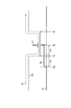
- FIG. 8 is a configuration diagram illustrating a configuration for performing a measurement method by the noise measurement apparatus according to the third embodiment of the present invention.
- FIG. 9 is a conceptual diagram conceptualizing a waveform indicating the position of the induced noise at the time when the noise reaches the first observation point in the third embodiment.
- FIG. 10 is a conceptual diagram conceptualizing a waveform indicating the position of the induced noise at the time when the noise reaches the second observation point in the third embodiment.
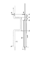
- FIG. 11 is a block diagram which shows the structure which implements the measuring method by the noise measuring device which concerns on the 4th Embodiment of this invention.
- FIG. 11 is a block diagram which shows the structure which implements the measuring method by the noise measuring device which concerns on the 4th Embodiment of this invention.
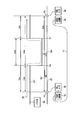
- FIG. 12 is a waveform diagram showing inductive noise waveforms measured by two voltage sensors according to the fourth embodiment at the same time coordinates.
- FIG. 13 is a block diagram which shows the structure which implements the measuring method by the noise measuring device which concerns on the 5th Embodiment of this invention.
- FIG. 14 is a block diagram which shows the structure which implements the measuring method by the noise measuring device which concerns on the 6th Embodiment of this invention.
- FIG. 15 is a waveform diagram showing, with the same time coordinates, noise waveforms respectively measured by the voltage sensors according to the sixth embodiment.
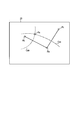
- FIG. 16 is a conceptual diagram illustrating a noise source analysis method performed by the noise source analyzer according to the sixth embodiment.
- FIG. 17 is a block diagram which shows the structure which implements the measuring method by the noise measuring device which concerns on the 7th Embodiment of this invention.
- FIG. 18 is a waveform diagram showing inductive noise waveforms respectively measured by the voltage sensors according to the seventh embodiment at the same time coordinates.
- FIG. 19 is a configuration diagram showing a configuration for performing a measurement method by the noise measurement apparatus according to the eighth embodiment of the present invention.
- FIG. 20 is a waveform diagram showing the waveforms of electromagnetic noise respectively measured by the voltage sensors according to the eighth embodiment at the same time coordinates.
- FIG. 1 is a configuration diagram showing a configuration of a noise measuring apparatus 1 according to the first embodiment of the present invention.
- symbol is attached
- the noise measuring device 1 includes two voltage sensors 2a and 2b, two optical signal processors 3a and 3b, a data collecting device 4, and a noise source analyzing device 5.
- the voltage sensors 2a and 2b are sensors that measure the potential (or other electric quantity such as current) of the electric wire 21 that is a measurement target for analyzing a noise source that is a cause of noise as a voltage.
- the voltage sensors 2a and 2b measure different points Pa and Pb of the electric wire 21, respectively.
- the voltage sensors 2a and 2b constantly measure the electric potential of the electric wire 21 and hold the measured value for at least a predetermined time.
- the voltage sensors 2a and 2b detect the exceeding potential as noise when the measuring potential exceeds a preset threshold value. When the voltage sensors 2a and 2b detect noise, they output a noise detection signal to the corresponding optical signal processors 3a and 3b, respectively, and record voltage data before and after the time when the noise is detected. The voltage sensors 2 a and 2 b output the recorded voltage data to the data collection device 4.
- the respective voltage sensors 2a and 2b are arranged before and after the time when the noise is detected. Record voltage data.
- the voltage sensors 2 a and 2 b output the recorded voltage data to the data collection device 4.
- the time when the noise is detected is a time that takes into account the delay time taken from when the noise is detected by the other voltage sensors 2a and 2b to when the noise detection signal indicating the detection of the noise is received. This delay time is preset in the voltage sensors 2a and 2b.
- each voltage sensor 2a, 2b has a time that is a delay time before the time when the noise detection signal is received from the voltage sensor 2a, 2b that detected the noise, as the time when the other voltage sensors 2a, 2b detected the noise. Ask for.
- the optical signal processors 3a and 3b are provided corresponding to the voltage sensors 2a and 2b, respectively.
- the optical signal processors 3a and 3b perform transmission, reception, and other processing of optical signals. All the optical signal processors 3 a and 3 b are connected to each other by an optical cable 11.
- An optical coupler may be connected to the optical cable 11.
- the optical signal processors 3a and 3b constantly transmit and receive signals for synchronizing the time of all the voltage sensors 2a and 2b.
- the optical signal processors 3a and 3b perform time synchronization with an accuracy of 10 nanoseconds or less.
- the optical signal processors 3a and 3b When the noise detection signals are input from the corresponding voltage sensors 2a and 2b, the optical signal processors 3a and 3b send the optical cable 11 to all the other optical signal processors 3a and 3b using the noise detection signals as optical signals. Call through. Further, when each of the optical signal processors 3a and 3b receives a noise detection signal as an optical signal from the other optical signal processors 3a and 3b, it outputs the noise detection signal to the corresponding voltage sensors 2a and 2b.
- the data collection device 4 collects voltage data from the voltage sensors 2a and 2b.
- the data collection device 4 processes the collected voltage data into analysis data for analyzing the noise source.
- the data collection device 4 outputs the processed analysis data to the noise source analysis device 5.
- the noise source analyzer 5 analyzes the noise source based on the analysis data input from the data collection device 4.
- the noise source analyzer 5 outputs information on the noise source from the analysis result.
- the information regarding the noise source is the position and direction of the noise source.
- a person may perform part or all of the processing performed by the data collection device 4 and the noise source analysis device 5.
- the outline of the noise source analysis method by the noise source analyzer 5 is as follows.
- the speed at which noise propagates through the electric wire 21 is the speed of light (hereinafter, unified and described as 0.2 [m / ns]).
- the noise source analyzer 5 analyzes a noise source by comparing time-series data of voltages indicating noise measured at each measurement location.
- FIG. 2 is a configuration diagram showing a configuration for performing the measurement method by the noise measurement apparatus 1 according to the present embodiment.
- the noise source 22 is outside the measurement points Pa and Pb of the two voltage sensors 2a and 2b.
- the distance of the electric wire 21 between the measurement points Pa and Pb of the two voltage sensors 2a and 2b is Lt [m]. It is assumed that the noise source 22 is on the voltage sensor 2b side outside the measurement points Pa and Pb of the two voltage sensors 2a and 2b. Noise Sn is generated from the noise source 22.
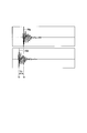
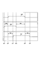
- FIG. 3 is a waveform diagram showing voltage data measured by the noise measuring apparatus 1 according to the present embodiment.
- the waveform diagram shown in FIG. 3 displays two voltage data respectively measured by the two voltage sensors 2a and 2b with their times matched.
- the waveform Wa is voltage data measured by the voltage sensor 2a far from the noise source 22.
- a waveform Wb is voltage data measured by the voltage sensor 2 b closer to the noise source 22.
- the time ta indicates the time when the noise Sn is detected by the voltage sensor 2a (the time when the potential at the measurement point Pa exceeds the threshold).
- the time tb indicates the time when the noise Sn is detected by the voltage sensor 2b (the time when the potential of the measurement point Pb exceeds the threshold).
- Time T1 is the time difference between time ta and time tb.
- the noise source analyzer 5 analyzes the noise source 22 as follows.
- the noise source analyzer 5 can determine whether the noise source 22 is outside or inside between the two measurement points Pa and Pb. If it is known in advance that the noise source 22 is outside the two measurement locations Pa and Pb, the noise source analyzer 5 does not have to make such a determination.
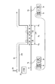
- FIG. 4 is a configuration diagram illustrating a configuration in which the noise measurement apparatus 1 according to the present embodiment is tested.
- the configuration of the experiment is as follows.
- As the electric wire 21, a 120 [m] two-core cable is used. One end of the electric wire 21 is measured by the voltage sensor 2b, and the other end of the electric wire 21 is measured by the voltage sensor 2a.
- a voltage of +5 [V] is applied to the electric wire 21 from the DC power supply 31.
- the two optical cables 11 connecting the optical signal processors 3 a and 3 b are connected by an optical star coupler 12. Noise Sn is applied to the measurement point Pa of the voltage sensor 2a by the noise generator 22a.
- the voltage sensor 2a detects the noise Sn at time ta, and sequentially detects the optical signal processor 3a, the optical cable 11 on the voltage sensor 2a side, the optical star coupler 12, the optical cable 11 on the voltage sensor 2b side, and the optical signal processor 3b. Then, a noise detection signal is transmitted to the voltage sensor 2b.
- the voltage sensor 2b When the voltage sensor 2b receives the noise detection signal, the voltage sensor 2b records the voltage data before and after the time point from the detection of the noise Sn by the voltage sensor 2a until the reception of the noise detection signal. Thereby, the respective voltage data measured by the two voltage sensors 2a and 2b at around the same time are recorded.
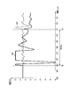
- FIG. 5 is a graph showing a trend graph of voltage data obtained by the experiment shown in FIG.
- the graph shown in FIG. 5 is displayed by the noise source analyzer 5.
- the time difference between the times ta and tb when the two voltage sensors 2a and 2b detect the noise Sn is 600 [ns].
- This length coincides with the length of the electric wire 21 connecting the two voltage sensors 2a and 2b.
- the noise source analyzer 5 outputs the above analysis process and analysis results.
- the two voltage sensors 2a and 2b are used to measure the potentials at the two points Pa and Pb of the electric wire 21 so that they are outside the section between the two measurement points Pa and Pb of the electric wire 21. Information for specifying the position of the noise source 22 can be obtained.
- FIG. 6 is a configuration diagram illustrating a configuration for performing the measurement method by the noise measurement apparatus 1 according to the second embodiment of the present invention.
- the configuration of the noise measuring apparatus 1 according to this embodiment is the same as that of the noise measuring apparatus 1 according to the first embodiment shown in FIG. Therefore, FIG. 6 illustrates a configuration necessary for the description of the present embodiment, and omits other configurations as appropriate.
- the noise source 22 is inside the measurement points Pa and Pb of the two voltage sensors 2a and 2b.
- the distance of the electric wire 21 between the measurement points Pa and Pb of the two voltage sensors 2a and 2b is Lt [m].
- the distance of the electric wire 21 between the measurement point Pa of the voltage sensor 2a and the noise source 22 is defined as La [m].
- the distance of the electric wire 21 between the measurement location Pb of the voltage sensor 2b and the noise source 22 is Lb [m].
- the noise Sn When noise Sn is generated from the noise source 22, the noise Sn propagates in the direction of both sides of the electric wire 21 at the speed of light. Noise Sn propagating to both sides of the electric wire 21 is detected by voltage sensors 2a and 2b provided on both sides of the electric wire 21, respectively. Similarly to the first embodiment, the data collection device 4 outputs analysis data to the noise source analysis device 5 based on the voltage data collected by the voltage sensors 2a and 2b.
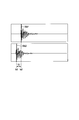
- FIG. 7 is a waveform diagram showing voltage data measured by the noise measuring apparatus 1 according to the present embodiment.
- the waveform diagram shown in FIG. 7 displays two voltage data respectively measured by the two voltage sensors 2a and 2b with their times matched.
- the waveform Wa2 is voltage data measured by the voltage sensor 2a far from the noise source 22.
- a waveform Wb2 is voltage data measured by the voltage sensor 2b closer to the noise source 22.
- the time ta2 indicates the time when the noise Sn is detected by the voltage sensor 2a (the time when the potential at the measurement point Pa exceeds the threshold).
- Time tb2 indicates the time when noise Sn is detected by the voltage sensor 2b (the time when the potential at the measurement point Pb exceeds the threshold).
- Time T2 is the time difference between time ta2 and time tb2.
- the noise source analysis device 5 analyzes the noise source 22 based on the analysis data input from the data collection device 4 as follows.
- the noise source analyzer 5 determines whether or not the noise source 22 is inside the two measurement points Pa and Pb, as in the first embodiment.
- the time during which the noise Sn propagates the distance Lt between the measurement points Pa and Pb of the electric wire 21 is obtained by Lt ⁇ light velocity (0.2 [m / ns]).
- the noise source analyzer 5 determines that the noise source 22 is inside the two measurement points Pa and Pb. To do. If it is known in advance that the noise source 22 is inside the measurement points Pa and Pb of the two voltage sensors 2a and 2b, the noise source analyzer 5 does not need to make such a determination. Good.
- the difference between the distances La and Lb between the noise source 22 and the two measurement points Pa and Pb is the speed of light ⁇ time T2.
- the total of the two distances La and Lb is the length Lt of the electric wire 21 between the two measurement points Pa and Pb.
- La + Lb Lt Formula (1)
- light velocity ⁇ T2 (2) From these equations, two distances La and Lb are obtained. Thereby, the noise source analyzer 5 identifies the position of the noise source 22.
- the noise in the section between the two measurement points Pa and Pb of the electric wire 21 is measured by measuring the potentials of the two points Pa and Pb of the electric wire 21 by the two voltage sensors 2a and 2b. Information for identifying the location of the source 22 can be obtained.
- FIG. 8 is a configuration diagram illustrating a configuration for performing the measurement method by the noise measurement apparatus 1 according to the third embodiment of the present invention.
- the configuration of the noise measuring apparatus 1 according to this embodiment is the same as that of the noise measuring apparatus 1 according to the first embodiment shown in FIG. Therefore, FIG. 8 illustrates a configuration necessary for describing the present embodiment, and omits other configurations as appropriate.
- the electric wire 21 shall be extended linearly, and the distance of the perpendicular
- electrostatic induction or electromagnetic induction occurs in a section between the electric wire 21 where the two voltage sensors 2a and 2b are installed and the observation point Pw and the observation point Px. Close and parallel in distance.
- the observation point Py is located approximately in the middle between the observation point Pw and the observation point Px.
- the noise source 22 is outside the two observation points Pw and Px of the electric wire 21n.
- the distance of the electric wire 21 between the observation point Pw and the observation point Px is Lwx [m].
- the noise Sn generated from the noise source 22 propagates at the speed of light from the observation point Pw side to the observation point Px side through the electric wire 21n.
- noise Sni due to induction hereinafter referred to as “induction noise Sni”
- induction noise Sni noise Sni due to induction
- FIG. 9 is a conceptual diagram conceptualizing a waveform indicating the position of the induced noise Sni when the noise Sn reaches the observation point Py.
- the tip of the noise Sn propagation direction (the direction of the observation point Px) of the induced noise Sni generated at the observation point Pw has reached the observation point Py.
- the tip of the induced noise Sni generated at the observation point Pw in the direction opposite to the propagation direction of the noise Sn reaches from the observation point Pw to the point Pyr equivalent to the distance Lwy between the observation point Pw and the observation point Py. Yes.
- FIG. 10 is a conceptual diagram conceptualizing a waveform indicating the position of the induction noise Sni when the noise Sn reaches the observation point Pz.
- induced noise Sni is generated in which a waveform having the same length as the distance Lwx between the observation point Pw and the observation point Px spreads in both directions from the observation point Pw. That is, the induction noise Sni having a waveform having a width twice as large as the distance Lwx is generated around the observation point Pw. Further, after the noise Sn passes the observation point Px that is the end of the section where the induction noise Sni occurs, the induction noise Sni does not occur in the electric wire 21.
- the induced noise Sni having a waveform having a width twice as large as the distance Lwx is propagated in the direction opposite to the propagation direction of the noise Sn.
- the rear end of the induction noise Sni is located at a point Pzr equivalent to the distance Lxz between the observation point Px and the observation point Pz from the observation point Px.
- the induction noise Sni that propagates in the same direction as the propagation direction of the noise Sn propagates at the same light speed as the noise Sn. For this reason, when the noise Sn reaches the observation point Pz, the waveforms of all the induction noise Sni generated between the two observation points Pw and Px where the induction occurs are in the same position as the observation point Pz where the noise Sn is located. It is in.
- the induction noise Sni propagates in the same direction as the propagation direction of the original noise Sn as the induction source and in the opposite direction.
- the induction noise Sni propagating in the same direction as the original noise Sn has substantially the same waveform as that of the original noise Sn, and the width is reduced by induction.
- the induction noise Sni that propagates in the opposite direction to the original noise Sn is twice as long as the interval in which induction occurs.
- a noise signal (inductive noise Sni) having a waveform close to the original noise Sn is detected.
- the voltage sensor 2b having the measurement point Pb in the direction opposite to the propagation direction of the original noise Sn a noise signal that lasts for a time obtained by dividing a distance twice as long as the induction occurs (between two observation points Pw and Px) by the speed of light ( Inductive noise Sni) is detected.
- the voltage sensor 2b may not be able to detect the noise signal significantly.
- the case where the noise signal cannot be detected significantly is, for example, when the noise signal is intermittently detected without being continued, or when the detection level (voltage or the like) of the noise signal is low. Even in such a case, it may be determined that the voltage sensor 2b is in the direction opposite to the propagation direction of the original noise Sn. Therefore, any determination may be made as long as the propagation direction of the original noise Sn is determined based on the difference in the waveform of the noise signal detected by the two voltage sensors 2a and 2b.
- the noise source analyzer 5 estimates that the noise is the induced noise Sni generated by the guidance in a certain section. For example, the noise source analysis device 5 uses the induced noise Sni generated by induction in a certain section when a noise signal having a shorter width than the noise signal detected by one voltage sensor 2b is detected by the other voltage sensor 2a. It is estimated that. In this case, the noise source analyzer 5 detects a noise signal having a long width of the electric wire 21n on which the noise Sn may be superimposed by the noise source 22 that has generated the noise Sn induced by the induction noise Sni. Estimated to be in the direction.
- the noise source 22 that causes the induction noise Sni generated by induction in a certain section by measuring the potentials of the two places Pa and Pb of the electric wire 21 by the two voltage sensors 2a and 2b. The information for specifying the position of can be obtained.
- FIG. 11 is a block diagram which shows the structure which implements the measuring method by the noise measuring device 1 which concerns on the 4th Embodiment of this invention.
- FIG. 11 mainly shows induced noise Sni generated at the observation point Pw.
- FIG. 12 is a waveform diagram showing the waveforms Wa4 to Wb4 of the induction noise Sni measured by the two voltage sensors 2a and 2b, respectively, at the same time coordinates.
- Waveform Wa4 is voltage data measured by the voltage sensor 2a far from the noise source 22.
- a waveform Wb4 is voltage data measured by the voltage sensor 2b closer to the noise source 22.
- the time ta4f indicates the time (the time when the potential of the measurement point Pa exceeds the threshold) when the tip of the induction noise Sni (the start time of the noise signal) is detected by the voltage sensor 2a.
- the time ta4r indicates the time (the time when the potential of the measurement point Pa becomes equal to or lower than the threshold) when the voltage sensor 2a detects the rear end of the induction noise Sni (the end point of the noise signal).
- the time tb4f indicates the time (the time when the potential of the measurement point Pb exceeds the threshold) when the tip of the induced noise Sni (the start time of the noise signal) is detected by the voltage sensor 2b.
- Time tb4r indicates the time (the time when the potential of the measurement point Pb becomes equal to or lower than the threshold) when the voltage sensor 2b detects the rear end of the induced noise Sni (the end point of the noise signal).
- the induced noise Sni generated at the observation point Pw propagates at the speed of light in the same direction as the propagation direction of the noise Sn generated from the noise source 22 and in the opposite direction.
- the time ta4f detected by the voltage sensor 2a is the time after the lapse of time from the time generated at the observation point Pw to the measurement point Pa of the voltage sensor 2a at the speed of light.
- the induced noise Sni generated at the observation point Pw propagating in the opposite direction to the noise Sn is detected as a noise signal by the voltage sensor 2b earliest compared to the induced noise Sni generated thereafter.
- the time tb4f detected by the voltage sensor 2b is the time after the lapse of time from the time generated at the observation point Pw to the measurement point Pb of the voltage sensor 2b at the speed of light.
- the position of the observation point Pw which is the start position of the section in which the induced noise Sni is induced, can be specified from the above two formulas.
- the noise source analyzer 5 estimates the start position of the section where guidance occurs based on the above-described method.
- the induction noise Sni generated at the observation point Px will be described. Even when it occurs at the observation point Px, similarly to the case where it occurs at the observation point Pw, it propagates at the speed of light in the same direction as the propagation direction of the noise Sn and in the opposite direction.
- the time ta4r detected by the voltage sensor 2a is the time after the lapse of time from the time generated at the observation point Px to the measurement point Pa of the voltage sensor 2a at the speed of light.
- the induced noise Sni generated at the observation point Px propagating in the opposite direction to the noise Sn is detected as a noise signal indicating the end of the induced noise Sni generated in the section where the induction occurs.
- the time tb4r detected by the voltage sensor 2b is the time after the lapse of time from the time generated at the observation point Px to the measurement point Pb of the voltage sensor 2b at the speed of light.
- the distance of the electric wire 21 between them is Lbx
- the distance of the electric wire 21 between the measurement point Pa of the voltage sensor 2a and the observation point Px is Lax
- the noise source analyzer 5 estimates the end position of the section where guidance occurs based on the above-described method. Note that the noise source analyzer 5 may be configured to estimate only one of the start position and the end position of the section where the guidance occurs.
- time width Twb of the waveform of the induction noise Sni detected by the voltage sensor 2b is obtained from the following equation.
- the waveform Wb4 measured by the voltage sensor 2b is clearly illustrated, but it is not necessarily clear. If either the front end or the rear end of the waveform Wb4 can be recognized, information on the section in which the guidance occurs can be obtained.
- FIG. 13 is a block diagram which shows the structure which implements the measuring method by the noise measuring device 1 which concerns on the 5th Embodiment of this invention.
- the configuration of the noise measuring apparatus 1 according to this embodiment is the same as that of the noise measuring apparatus 1 according to the first embodiment shown in FIG. Therefore, FIG. 13 illustrates a configuration necessary for describing the present embodiment, and omits other configurations as appropriate.
- the electric wire 21s is obtained by branching the electric wire 21sp to which the noise source 22 is connected at the branch point Ps in the section where the electric wire 21 is induced in the electric wire 21n according to the third embodiment shown in FIG. .
- Noise Sn generated from the noise source 22 propagates in each of the two directions of the electric wire 21s at the branch point Ps of the electric wire 21s. Therefore, the induction noise Sni is generated in a section where the induction of the electric wire 21 is caused by each of the two noises Sn branched at the branch point Ps of the electric wire 21s.
- the noise signal indicating the induction noise Sni has almost no characteristics such as the waveform width as described in the third embodiment or the fourth embodiment. Therefore, in the analysis method of the noise source 22 according to the third embodiment and the fourth embodiment, not much useful information regarding the noise source 22 is obtained.
- the noise source analyzer 5 executes the analysis method according to the first embodiment or the second embodiment.
- the analysis method according to the first embodiment or the second embodiment assumes that the noise sensor 22 is present in the electric wire 21 to be detected by the voltage sensors 2a and 2b. .
- the obtained analysis result is used to specify the position of the branch point Ps in the section where the induction of the electric wire 21s as shown in FIG.
- the analysis result by the analysis method according to the first embodiment or the second embodiment can be used to specify the position of the section where the guidance occurs.
- FIG. 14 is a block diagram which shows the structure which implements the measuring method by the noise measuring device 1 which concerns on the 6th Embodiment of this invention.
- the configuration of the noise measuring apparatus 1 according to this embodiment is the same as that of the noise measuring apparatus 1 according to the first embodiment shown in FIG. 1 except that a voltage sensor 2c and an optical signal processor 3c are added. is there. Therefore, FIG. 14 illustrates a configuration necessary for describing the present embodiment, and omits other configurations as appropriate.
- the noise source 22 is on the planar conductive plate 23.
- the planar conductive plate 23 is a ground plane installed on the floor or the like in a mesh form, or a solid common plane in the electronic substrate. Noise Sn generated from the noise source 22 propagates concentrically around the noise source 22 at the speed of light.
- the measurement points Pa, Pb, and Pc of the three voltage sensors 2a, 2b, and 2c are on the conductive plate 23.
- the voltage sensor 2c and the optical signal processor 3c are the same as the voltage sensors 2a and 2b and the optical signal processors 3a and 3b described in the first embodiment.
- the optical signal processors 3a to 3c constantly transmit and receive signals for synchronizing the time of all the voltage sensors 2a to 2c.
- a configuration using three voltage sensors 2a to 2c will be described, but the number of voltage sensors 2a to 2c may be any number as long as there are three or more.
- FIG. 15 is a waveform diagram showing the waveforms Sn6, Wb6, and Wc6 of the noise Sn measured by the voltage sensors 2a, 2b, and 2c according to the present embodiment at the same time coordinates.
- FIG. 16 is a conceptual diagram showing an analysis method of the noise source 22 by the noise source analyzer 5 according to the present embodiment.
- times ta6, tb6 and tc6 are times when voltage sensors 2a, 2b and 2c detect noise Sn, respectively.
- Time Tab is a time difference between time ta6 and time tb6.
- Time Tac is a time difference between time ta6 and time tc6.
- the times ta6 to tc6 at which the noise Sn is detected by the voltage sensors 2a to 2c differ depending on the distances between the measurement points Pa to Pc and the noise source 22.
- the time tb6 detected by the voltage sensor 2b at the measurement point Pb closest to the noise source 22 is the earliest.
- the time tc6 detected by the voltage sensor 2c at the measurement point Pc farthest from the noise source 22 is the latest.
- the trajectory Cab which is a set of points where the time difference between the time taken to reach the measurement point Pa of the voltage sensor 2a and the time taken to the measurement point Pb of the voltage sensor 2b at the light speed becomes the time Tab.
- a trajectory Cac which is a set of points at which the time difference between the time taken to reach the measurement point Pa of the voltage sensor 2a and the time taken to the measurement point Pc of the voltage sensor 2c at the light speed becomes time Tac, is obtained.
- the intersection Po of the two trajectories Cab and Cac obtained in this way is a position where it is estimated that the noise source 22 is present.
- the noise source analyzer 5 identifies the position of the noise source 22.
- the noise source 22 at an arbitrary position on the conductive plate 23 is measured by measuring the potentials of the three portions Pa to Pc of the planar conductive plate 23 by the three voltage sensors 2a to 2c.
- the information for specifying the position of can be obtained.
- FIG. 17 is a block diagram which shows the structure which implements the measuring method by the noise measuring device 1 which concerns on the 7th Embodiment of this invention.
- the configuration according to the present embodiment is the same as the configuration according to the sixth embodiment shown in FIG. Therefore, here, a different part from 6th Embodiment is mainly demonstrated.
- the electric wire 21n is an electric wire with a noise source 22.
- the electric wire 21n is close to the conductive plate 23 on which the three voltage sensors 2a to 2c are installed, and the distance between the observation point Pw and the observation point Px at a distance where induction occurs.
- the noise Sn generated from the noise source 22 propagates through the electric wire 21n at the speed of light. From the time when the noise Sn reaches the observation point Pw of the electric wire 21n to the time when it passes through the observation point Px, the induction noise Sni is superimposed on the conductive plate 23 by the induction of the noise Sn.
- the induction noise Sni propagates concentrically at the speed of light with the point superimposed on the guide plate 23 as the center. Therefore, the induction noise Sni spreads concentrically starting from a point arranged in a line in the section from the observation point Pw to the observation point Px on the conductive plate 23 adjacent to the electric wire 21n.
- the induced noise Sni propagating from the observation point Pw reaches earlier than the induced noise Sni propagating from the observation point Px. For this reason, the induced noise Sni detected at an arbitrary point on the guide plate 23 continues from the time when the induced noise Sni propagating from the observation point Pw is detected to the time when the induced noise Sni propagating from the observation point Px is detected.
- the waveform has a time width to
- FIG. 18 is a waveform diagram showing the waveforms Wa7, Wb7, and Wc7 of the induction noise Sni measured by the voltage sensors 2a, 2b, and 2c according to the present embodiment at the same time coordinates.
- the time at which the waveforms Wa7 to Wc7 of the induced noise Sni are first detected (the time at which the waveforms Wa7 to Wc7 are located) ta7f to tc7f generate the induced noise Sni that propagates from the observation point Pw. The detected time.
- the position of the observation point Pw is estimated from the two time differences Tabf and Tacf obtained in this way by performing arithmetic processing in the same manner as in the sixth embodiment.
- the time at which the waveforms Wa7 to Wc7 of the induced noise Sni were detected last (time at the rear end of each Wa7 to Wc7) ta7r to tc7r in each voltage sensor 2a to 2c, respectively, is induced noise Sni that propagates from the observation point Px. Is the time when
- the time difference Tabr between the times ta7r and 7b7r when the two voltage sensors 2a and 2b detect the induction noise Sni propagating from the observation point Px, respectively, is obtained. . Also, at the times ta7r and tc7r at which the two voltage sensors 2a and 2c detect the induced noise Sni propagating from the observation point Px, respectively, from the waveforms Wa7 and Wc7 measured by the two different voltage sensors 2a and 2c. The time difference Tacr is obtained.
- the position of the observation point Px is estimated from the two time differences Tabr and Tacr obtained in this way by performing arithmetic processing in the same manner as in the sixth embodiment.
- the noise source analyzer 5 estimates a location where the induced noise Sni is generated in order to identify the noise source 22.
- the three voltage sensors 2a to 2c are used to measure the potentials of the three locations Pa to Pc of the planar conductive plate 23, so that the location where the induction noise Sni is superimposed on the conductive plate 23 is determined. Can be identified.
- FIG. 19 is a configuration diagram showing a configuration for performing a measurement method by the noise measurement apparatus 1 according to the eighth embodiment of the present invention.
- the configuration according to the present embodiment is the same as the configuration according to the sixth embodiment shown in FIG. 14, and therefore different parts will be mainly described.
- the noise source 22m transmits electromagnetic noise Snm to the space.
- the noise source 22m is a radio wave source of illegal radio waves emitted in space, or a wiring portion of a high voltage device that generates high frequency noise.
- Electromagnetic field probes 13a, 13b, and 13c are attached to the voltage sensors 2am, 2bm, and 2cm, respectively.
- the voltage sensors 2am to 2cm are the same as the voltage sensors 2a to 2c according to the sixth embodiment.
- the voltage sensors 2am to 2cm measure the electromagnetic noise Snm at three different places Pa to Pc in the space, respectively. Any sensor may be used as long as the electromagnetic noise Snm can be measured. Since the electromagnetic noise Snm does not propagate on the plane, the measurement points Pa to Pc of the three voltage sensors 2am to 2cm do not have to be located on the same plane, and may be arbitrary positions in the space.
- FIG. 20 is a waveform diagram showing the waveforms Wa8, Wb8, and Wc8 of the electromagnetic noise Snm measured by the voltage sensors 2am, 2bm, and 2cm according to the present embodiment at the same time coordinates.
- times ta8, tb8, and tc8 are times when voltage sensors 2am, 2bm, and 2cm detect electromagnetic noise Snm, respectively.
- Time Tab8 is a time difference between time ta8 and time tb8.
- Time Tac8 is a time difference between time ta8 and time tc8.
- Time Tbc8 is the time difference between time tb8 and time tc8.
- the noise source analyzer 5 determines the position of the noise source 22m based on the measurement points Pa to Pc of the voltage sensors 2am to 2cm and the two times Tab8 and Tab8 shown in FIG. Identify.
- the electromagnetic noise Snm propagates in the air, the light velocity is calculated as 0.3 [m / ns].
- the noise source analyzer 5 may further specify the position of the noise source 22m using another time Tbc8. Thereby, the range in which the noise source 22m is located can be further limited and specified.
- the position of the noise source 22m at an arbitrary position in the space is specified by measuring the electromagnetic noise Snm at three points Pa to Pc in the certain space by the three sensors 2am to 2cm. Information to do.
- the noise source analyzer 5 may be configured to perform analysis according to any number of embodiments as long as the noise source analysis device 5 is configured to perform analysis according to at least its own embodiment. Good.
- the present invention is not limited to the above-described embodiment as it is, and can be embodied by modifying constituent elements without departing from the scope of the invention in the implementation stage.
- various inventions can be formed by appropriately combining a plurality of components disclosed in the embodiment. For example, some components may be deleted from all the components shown in the embodiment.
- constituent elements over different embodiments may be appropriately combined.
Landscapes
- Physics & Mathematics (AREA)
- General Physics & Mathematics (AREA)
- Electromagnetism (AREA)
- Locating Faults (AREA)
- Measurement Of Mechanical Vibrations Or Ultrasonic Waves (AREA)
Abstract
Description
図1は、本発明の第1の実施形態に係るノイズ測定装置1の構成を示す構成図である。なお、図面における同一部分には同一符号を付してその詳しい説明を省略し、異なる部分について主に述べる。
図6は、本発明の第2の実施形態に係るノイズ測定装置1による測定方法を実施する構成を示す構成図である。本実施形態に係るノイズ測定装置1の構成は、図1に示す第1の実施形態に係るノイズ測定装置1と同様の構成である。従って、図6では、本実施形態の説明に必要な構成を図示し、その他の構成は適宜省略する。
|La-Lb|=光速度×T2 …式(2)
これらの式から、2つの距離La,Lbが求まる。これにより、ノイズ源分析装置5は、ノイズ源22の位置を特定する。
図8は、本発明の第3の実施形態に係るノイズ測定装置1による測定方法を実施する構成を示す構成図である。本実施形態に係るノイズ測定装置1の構成は、図1に示す第1の実施形態に係るノイズ測定装置1と同様の構成である。従って、図8では、本実施形態の説明に必要な構成を図示し、その他の構成は適宜省略する。また、電線21は、直線状に延びているものとし、電線21と垂直方向の距離については、無視できるものとする。
図11は、本発明の第4の実施形態に係るノイズ測定装置1による測定方法を実施する構成を示す構成図である。図11は、観測点Pwで発生した誘導ノイズSniを主に示している。図12は、2つの電圧センサ2a,2bでそれぞれ測定された誘導ノイズSniの波形Wa4~Wb4を同一の時刻座標で示した波形図である。
また、2つの電圧センサ2a,2bの測定箇所Pa,Pb間の距離をLabとすると、次式が成り立つ。
ここで、測定箇所Pa,Pb間の距離Labは、予め測定することができる。
また、2つの電圧センサ2a,2bの測定箇所Pa,Pb間の距離をLabとすると、次式が成り立つ。
従って、上記2式より、誘導ノイズSniが誘導される区間の終了位置である観測点Pxの位置を特定することができる。
ここで、ノイズSnと反対方向に伝播し、電圧センサ2bで検出される誘導ノイズSniの幅は、第3の実施形態で述べたように、誘導が生じる区間の距離Lwxの2倍である。従って、次式により、誘導が生じる区間の距離Lwxが求まる。
上式により、ノイズ源分析装置5は、誘導が生じる区間の距離Lwxを推定する。
図13は、本発明の第5の実施形態に係るノイズ測定装置1による測定方法を実施する構成を示す構成図である。本実施形態に係るノイズ測定装置1の構成は、図1に示す第1の実施形態に係るノイズ測定装置1と同様の構成である。従って、図13では、本実施形態の説明に必要な構成を図示し、その他の構成は適宜省略する。
図14は、本発明の第6の実施形態に係るノイズ測定装置1による測定方法を実施する構成を示す構成図である。本実施形態に係るノイズ測定装置1の構成は、図1に示す第1の実施形態に係るノイズ測定装置1において、電圧センサ2c及び光信号処理器3cを追加した点以外は、同様の構成である。従って、図14では、本実施形態の説明に必要な構成を図示し、その他の構成は適宜省略する。
図17は、本発明の第7の実施形態に係るノイズ測定装置1による測定方法を実施する構成を示す構成図である。本実施形態に係る構成は、図14に示す第6の実施形態に係る構成と同様である。従って、ここでは、第6の実施形態と異なる部分について主に説明する。
図19は、本発明の第8の実施形態に係るノイズ測定装置1による測定方法を実施する構成を示す構成図である。本実施形態に係る構成は、図14に示す第6の実施形態に係る構成と同様の構成であるため、異なる部分について主に説明する。
Claims (13)
- 互いに時刻同期された複数のセンサでノイズを測定し、
前記複数のセンサでそれぞれ測定された前記ノイズのデータに基づいて、前記ノイズの発生原因であるノイズ源を特定するための分析をすること
を含むことを特徴とするノイズ源分析方法。 - 前記分析は、前記複数のセンサでそれぞれ前記ノイズが測定された時刻の時刻差、及び前記複数のセンサの検出箇所の間の距離に基づいて、前記複数のセンサの検出箇所の間に前記ノイズ源があるか否かを判断すること
を特徴とする請求項1に記載のノイズ源分析方法。 - 前記分析は、前記複数のセンサでそれぞれ前記ノイズが測定された時刻の時刻差、及び前記複数のセンサの検出箇所の間の距離に基づいて、前記複数のセンサの検出箇所の間にある前記ノイズ源の位置を判断すること
を特徴とする請求項1に記載のノイズ源分析方法。 - 前記分析は、判断した前記ノイズ源の位置に前記ノイズ源がない場合、誘導により前記ノイズが生じたと判断すること
を特徴とする請求項3に記載のノイズ源分析方法。 - 前記分析は、前記複数のセンサでそれぞれ前記ノイズが測定された時刻の時刻差、及び前記複数のセンサの検出箇所の間の距離に基づいて、原ノイズが前記ノイズを誘導により発生させた位置を判断すること
を特徴とする請求項1に記載のノイズ源分析方法。 - 前記分析は、前記複数のセンサでそれぞれ前記ノイズが測定された時刻に基づいて、前記ノイズの伝播方向を判断すること
を特徴とする請求項1に記載のノイズ源分析方法。 - 前記分析は、前記複数のセンサでそれぞれ測定された前記ノイズの波形に基づいて、前記ノイズが原ノイズの誘導により発生したことを判断すること
を特徴とする請求項1に記載のノイズ源分析方法。 - 前記分析は、前記複数のセンサでそれぞれ測定された前記ノイズの波形の差異に基づいて、前記ノイズを誘導により発生させた前記原ノイズの伝播方向を判断すること
を特徴とする請求項7に記載のノイズ源分析方法。 - 前記分析は、前記複数のセンサでそれぞれ前記ノイズが測定された時刻の時刻差、及び前記複数のセンサの検出箇所の間の距離に基づいて、前記原ノイズが前記ノイズを誘導により発生させた位置を判断すること
を特徴とする請求項7に記載のノイズ源分析方法。 - 前記分析は、前記複数のセンサのうち1つで測定された前記ノイズの波形に基づいて、前記原ノイズが前記ノイズを誘導により発生させた区間の距離を判断すること
を特徴とする請求項7に記載のノイズ源分析方法。 - 前記複数のセンサにより、少なくとも3箇所で、前記ノイズを測定し、
前記分析は、前記複数のセンサでそれぞれ前記ノイズが測定された時刻の少なくとも2つの時刻差に基づいて、前記ノイズ源の位置を判断すること
を特徴とする請求項1に記載のノイズ源分析方法。 - 前記複数のセンサにより、少なくとも3箇所で、前記ノイズを測定し、
前記分析は、前記複数のセンサでそれぞれ前記ノイズが測定された時刻の少なくとも2つの時刻差に基づいて、原ノイズが前記ノイズを誘導により発生させた位置を判断すること
を特徴とする請求項1に記載のノイズ源分析方法。 - 互いに時刻同期され、ノイズを測定する複数のセンサと、
前記複数のセンサでそれぞれ測定された前記ノイズのデータに基づいて、前記ノイズの発生原因であるノイズ源を特定するための分析をする分析手段と
を備えることを特徴とするノイズ源分析装置。
Priority Applications (6)
| Application Number | Priority Date | Filing Date | Title |
|---|---|---|---|
| KR1020177033026A KR102016828B1 (ko) | 2015-05-29 | 2015-05-29 | 노이즈원 분석 방법 |
| JP2017521327A JP6519653B2 (ja) | 2015-05-29 | 2015-05-29 | ノイズ源分析方法 |
| PCT/JP2015/065604 WO2016194058A1 (ja) | 2015-05-29 | 2015-05-29 | ノイズ源分析方法 |
| US15/566,114 US10527664B2 (en) | 2015-05-29 | 2015-05-29 | Noise source analysis method |
| CN201580080211.3A CN107615083B (zh) | 2015-05-29 | 2015-05-29 | 噪声源分析方法 |
| TW104126351A TWI596353B (zh) | 2015-05-29 | 2015-08-13 | 雜訊源分析方法 |
Applications Claiming Priority (1)
| Application Number | Priority Date | Filing Date | Title |
|---|---|---|---|
| PCT/JP2015/065604 WO2016194058A1 (ja) | 2015-05-29 | 2015-05-29 | ノイズ源分析方法 |
Publications (1)
| Publication Number | Publication Date |
|---|---|
| WO2016194058A1 true WO2016194058A1 (ja) | 2016-12-08 |
Family
ID=57440294
Family Applications (1)
| Application Number | Title | Priority Date | Filing Date |
|---|---|---|---|
| PCT/JP2015/065604 Ceased WO2016194058A1 (ja) | 2015-05-29 | 2015-05-29 | ノイズ源分析方法 |
Country Status (6)
| Country | Link |
|---|---|
| US (1) | US10527664B2 (ja) |
| JP (1) | JP6519653B2 (ja) |
| KR (1) | KR102016828B1 (ja) |
| CN (1) | CN107615083B (ja) |
| TW (1) | TWI596353B (ja) |
| WO (1) | WO2016194058A1 (ja) |
Cited By (1)
| Publication number | Priority date | Publication date | Assignee | Title |
|---|---|---|---|---|
| JP2021025787A (ja) * | 2019-07-31 | 2021-02-22 | 国立大学法人京都大学 | 配電系統探査システム |
Families Citing this family (1)
| Publication number | Priority date | Publication date | Assignee | Title |
|---|---|---|---|---|
| DE102019118379A1 (de) * | 2018-07-12 | 2020-03-05 | Fanuc Corporation | Rauschquellenüberwachungsvorrichtung und Rauschquellenüberwachungsverfahren |
Citations (7)
| Publication number | Priority date | Publication date | Assignee | Title |
|---|---|---|---|---|
| JPS593273A (ja) * | 1982-06-29 | 1984-01-09 | Fujitsu Ltd | フオルトロケ−タ装置 |
| JPS6216017A (ja) * | 1985-07-12 | 1987-01-24 | 古河電気工業株式会社 | 送電線監視方法 |
| JPH06118119A (ja) * | 1992-08-17 | 1994-04-28 | Mitsubishi Electric Corp | 部分放電検出装置 |
| JP2001133503A (ja) * | 1999-11-01 | 2001-05-18 | Mitsubishi Heavy Ind Ltd | ノイズ検知方法及びこれを用いたメンテナンスシステム |
| JP2006258729A (ja) * | 2005-03-18 | 2006-09-28 | Hitachi Ltd | 起動領域モニタシステム用ノイズ監視システム |
| JP2010271104A (ja) * | 2009-05-20 | 2010-12-02 | Hitachi Ltd | 地絡位置標定方法及びその方法を実現するための地絡位置標定システム |
| US20140177694A1 (en) * | 2012-10-17 | 2014-06-26 | Ikanos Communications, Inc. | Method and apparatus for sensing noise signals in a wireline communications environment |
Family Cites Families (14)
| Publication number | Priority date | Publication date | Assignee | Title |
|---|---|---|---|---|
| JPH04264699A (ja) * | 1991-02-19 | 1992-09-21 | Hitachi Cable Ltd | 遠隔装置間の同期方法 |
| DE10064754A1 (de) * | 2000-12-22 | 2002-07-04 | Daimler Chrysler Ag | Verfahren und Anordnung zur Bestimmung eines Geräuschsignals einer Geräuschquelle |
| WO2004034734A1 (ja) * | 2002-10-08 | 2004-04-22 | Nec Corporation | アレイ装置および携帯端末 |
| JP5092752B2 (ja) * | 2005-12-22 | 2012-12-05 | 富士通株式会社 | ノイズチェック方法および装置並びにノイズチェックプログラムを記録したコンピュータ読取可能な記録媒体 |
| CN102047192B (zh) | 2008-05-30 | 2014-06-25 | 东芝三菱电机产业系统株式会社 | 远程监控装置 |
| JP5153693B2 (ja) | 2009-03-13 | 2013-02-27 | 東芝三菱電機産業システム株式会社 | データ収集システム |
| US8427333B2 (en) | 2009-06-29 | 2013-04-23 | General Electric Company | System and method for detecting lightning |
| DE102009033614B4 (de) * | 2009-07-17 | 2020-01-23 | Wolfgang Klippel | Anordnung und Verfahren zur Erkennung, Ortung und Klassifikation von Defekten |
| US9612271B2 (en) * | 2010-03-05 | 2017-04-04 | Ericsson Inc. | Evaluating noise and excess current on a power line |
| EP2620028B1 (en) * | 2010-09-23 | 2020-04-29 | BlackBerry Limited | System and method for dynamic coordination of radio resources usage in a wireless network environment |
| CA2871533C (en) * | 2012-03-13 | 2020-04-07 | Live Power Intelligence Company Na, Llc | Method and apparatus for monitoring electric power transmission, disturbances and forecasts |
| JP6288945B2 (ja) * | 2013-05-22 | 2018-03-07 | 三菱電機株式会社 | ノイズ源位置推定装置及びノイズ源位置推定プログラム |
| JP6277697B2 (ja) * | 2013-12-09 | 2018-02-14 | 富士通株式会社 | 設計支援装置、入力ベクタ生成方法、および入力ベクタ生成プログラム |
| CN104502732A (zh) * | 2014-11-07 | 2015-04-08 | 南京师范大学 | 基于stft时频分析的辐射源筛选和定位方法 |
-
2015
- 2015-05-29 WO PCT/JP2015/065604 patent/WO2016194058A1/ja not_active Ceased
- 2015-05-29 KR KR1020177033026A patent/KR102016828B1/ko active Active
- 2015-05-29 US US15/566,114 patent/US10527664B2/en active Active
- 2015-05-29 JP JP2017521327A patent/JP6519653B2/ja active Active
- 2015-05-29 CN CN201580080211.3A patent/CN107615083B/zh active Active
- 2015-08-13 TW TW104126351A patent/TWI596353B/zh active
Patent Citations (7)
| Publication number | Priority date | Publication date | Assignee | Title |
|---|---|---|---|---|
| JPS593273A (ja) * | 1982-06-29 | 1984-01-09 | Fujitsu Ltd | フオルトロケ−タ装置 |
| JPS6216017A (ja) * | 1985-07-12 | 1987-01-24 | 古河電気工業株式会社 | 送電線監視方法 |
| JPH06118119A (ja) * | 1992-08-17 | 1994-04-28 | Mitsubishi Electric Corp | 部分放電検出装置 |
| JP2001133503A (ja) * | 1999-11-01 | 2001-05-18 | Mitsubishi Heavy Ind Ltd | ノイズ検知方法及びこれを用いたメンテナンスシステム |
| JP2006258729A (ja) * | 2005-03-18 | 2006-09-28 | Hitachi Ltd | 起動領域モニタシステム用ノイズ監視システム |
| JP2010271104A (ja) * | 2009-05-20 | 2010-12-02 | Hitachi Ltd | 地絡位置標定方法及びその方法を実現するための地絡位置標定システム |
| US20140177694A1 (en) * | 2012-10-17 | 2014-06-26 | Ikanos Communications, Inc. | Method and apparatus for sensing noise signals in a wireline communications environment |
Cited By (2)
| Publication number | Priority date | Publication date | Assignee | Title |
|---|---|---|---|---|
| JP2021025787A (ja) * | 2019-07-31 | 2021-02-22 | 国立大学法人京都大学 | 配電系統探査システム |
| JP7420337B2 (ja) | 2019-07-31 | 2024-01-23 | 国立大学法人京都大学 | 配電系統探査システム |
Also Published As
| Publication number | Publication date |
|---|---|
| CN107615083B (zh) | 2020-05-19 |
| JP6519653B2 (ja) | 2019-05-29 |
| KR20170139070A (ko) | 2017-12-18 |
| TW201641951A (zh) | 2016-12-01 |
| KR102016828B1 (ko) | 2019-08-30 |
| CN107615083A (zh) | 2018-01-19 |
| JPWO2016194058A1 (ja) | 2018-02-01 |
| TWI596353B (zh) | 2017-08-21 |
| US20180095120A1 (en) | 2018-04-05 |
| US10527664B2 (en) | 2020-01-07 |
Similar Documents
| Publication | Publication Date | Title |
|---|---|---|
| CN108303626B (zh) | 基于分布式光纤传感阵列的局部放电超声测量系统与方法 | |
| KR100915712B1 (ko) | 전력기기의 부분방전위치 검출시스템 및 방전위치 검출방법 | |
| CN109085477B (zh) | 用于电力电缆分布式局部放电监测系统的信号识别和定位方法 | |
| EP1729096A1 (en) | Method and apparatus for determining the position of a disturbance in an optical fibre | |
| CN111095005A (zh) | 在电力输送系统中使用行波进行的距离保护 | |
| JP2017520750A (ja) | ケーブル故障診断方法及びシステム | |
| JP7304783B2 (ja) | 電力系統監視装置および方法 | |
| JP6910897B2 (ja) | 部分放電検出装置および部分放電検出方法 | |
| KR101548288B1 (ko) | 반사파 계측을 이용한 배선 진단 시스템 | |
| JP6774375B2 (ja) | 光ファイバ位置探索装置及びプログラム | |
| JPH06307896A (ja) | 分布型導波路センサ | |
| JP6519653B2 (ja) | ノイズ源分析方法 | |
| Hekmati | A novel acoustic method of partial discharge allocation considering structure-borne waves | |
| US11860214B2 (en) | System for monitoring the state of a cable through distributed reflectometry | |
| US12196605B2 (en) | Position detection device and position detection method | |
| CN109564256B (zh) | 用于对传输线路中的故障进行定位的基于行波的方法和用于该方法的装置 | |
| CN110726906B (zh) | 一种检测电缆长度的方法和系统 | |
| RU2676053C1 (ru) | Способ обнаружения дефекта электрического кабеля | |
| JP2012108011A (ja) | 事故点標定方法 | |
| CN115427823B (zh) | 噪声侵入位置估计装置和噪声侵入位置估计方法 | |
| US11927617B2 (en) | Apparatus for monitoring a condition of an electrical power transmission medium | |
| Fan et al. | A new time reversal method with extended source locating capability | |
| KR101392303B1 (ko) | 웨이블릿 변환을 이용한 주파수 해석식 자왜센서 | |
| KR101411036B1 (ko) | 고속 클럭을 이용한 전력케이블의 부분방전 위치추정시스템 | |
| JP3419924B2 (ja) | 部分放電測定方法 |
Legal Events
| Date | Code | Title | Description |
|---|---|---|---|
| 121 | Ep: the epo has been informed by wipo that ep was designated in this application |
Ref document number: 15894093 Country of ref document: EP Kind code of ref document: A1 |
|
| ENP | Entry into the national phase |
Ref document number: 2017521327 Country of ref document: JP Kind code of ref document: A |
|
| WWE | Wipo information: entry into national phase |
Ref document number: 15566114 Country of ref document: US |
|
| ENP | Entry into the national phase |
Ref document number: 20177033026 Country of ref document: KR Kind code of ref document: A |
|
| NENP | Non-entry into the national phase |
Ref country code: DE |
|
| 122 | Ep: pct application non-entry in european phase |
Ref document number: 15894093 Country of ref document: EP Kind code of ref document: A1 |